chapter 3 development of a matlab data acquisition...
TRANSCRIPT

Chapter 3
Development of a MATLAB Data Acquisition and
Control Toolbox for PIC Microcontrollers
3.1. Introduction
Data acquisition and control boards (DACBs) are essential for interfacing sensors/actuators
with decision making devices such as a personal computer (PC). Thus, DACBs are used in
monitoring/instrumentation applications involving machinery, process, environment, etc., and
in automatic control applications. Even though a variety of DACBs have become widely
available in the last 15 years, the systems that target the educational sector and provide support
for icon-based programming environments, such as LabVIEW [5] and Simulink [44], tend to
be quite expensive. Moreover, instructional labs generally may not require the intrinsic high-
performance features of many of the commercially available DACBs (e.g., high sampling rates,
high resolution analog to digital converters (A2Ds), etc.) for the typical electro-mechanical
laboratory experiments. This Chapter proposes a microcontroller-based data acquisition and
control (DAC) system that is particularly suitable for educators interested in developing lab
experiments that do not require high-cost, high-performance data acquisition hardware and
yet can benefit from the icon-based programming environment of Simulink.
Several recent papers [46–48] have focused on interfacing low-cost microcontrollers (such
as BASIC Stamp 2 (BS2) and Peripheral Interface Controller (PIC)) with icon-based pro-
gramming environments such as LabVIEW and Simulink. For example, in Chapter 2, we
concentrated primarily on endowing a PIC microcontroller with graphical user interface (GUI)
capability by exploiting the GUI tools of MATLAB/Simulink. However, the methodology of
Chapter 2 requires manually programming the microcontroller for all sensing, control compu-
tation, and actuation tasks and for serial communication with the GUI running on the PC. To
program a PIC microcontroller using PIC assembly programming language requires knowledge
and experience with the syntax of the PIC programming languages and is often tedious.
26
27
This Chapter proposes a PIC microcontroller-based low-cost DAC system that exploits
MATLAB and Simulink as the key software components for implementing DAC algorithms
using a block-diagram format. Specifically, this Chapter exploits a newly developed library of
PIC functions for Simulink and the serial communication capability of both the PIC micro-
controller and MATLAB to produce a seamless integration between them. The framework of
this Chapter completely obviates the need to manually program the PIC microcontroller by
creating a library of PIC microcontroller functions for Simulink. Specifically, the DAC tool-
box of this Chapter facilitates: i) automatic generation of proper PIC assembly codes for a
variety of sensors and actuators; ii) automatic programming of the PIC microcontroller; and
iii) data communication between the PIC microcontroller and MATLAB. In an instructional
laboratory, this approach allows instructors and students to focus on hardware-in-the-loop im-
plementation, experimental validation, and industry-style rapid control prototyping. Finally,
this Chapter is in the spirit of Chapter 4, which provides a MATLAB DAC toolbox for the BS2
microcontrollers. However, whereas the BS2 microcontroller costs over $45 and includes only
digital input/output (I/O) functionality, thus requiring external A2Ds to interface with ana-
log sensors, the PIC16F74 microcontroller, used in this Chapter, costs under $5 and includes
built-in A2D functionality.
The rest of the Chapter is organized as follows. In Section 3.2, we describe the PIC mi-
crocontroller and the related development hardware. In Section 3.3, we describe the software
environment used in this Chapter. In Section 3.4, we give details concerning the software
integration of Simulink with the PIC microcontroller. In Section 3.5, we illustrate the func-
tionality and capability of the DAC hardware and software of this Chapter by performing
position control of a DC motor. Finally, In Section 3.6, we provide some concluding remarks.
3.2. Hardware Environment
The main components of the DAC hardware of this Chapter are a PIC microcontroller,
a PIC-PG2C programmer, and a PIC development board. A DB-9 serial cable is used to
interface the programmer/development board to a PC which hosts the MATLAB DAC toolbox.
Specifically, the DB-9 cable allows i) programming the PIC microcontroller from the PC and
28
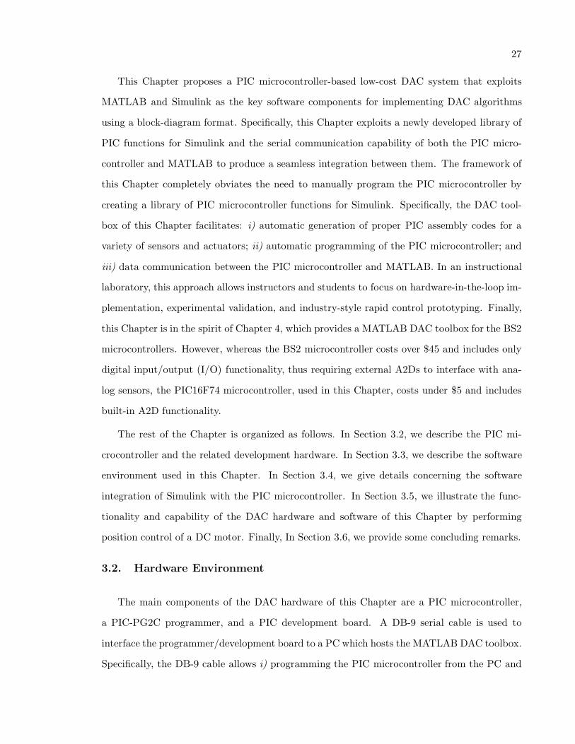
ii) data communication between the PIC and the PC. In this Chapter, an IBM-compatible
Pentium 4 PC running Microsoft Windows XP operating system is used. See Figure 3.1 for a
pictorial representation of the aforementioned hardware environment.
PIC development board
PIC-PG2C programmer
PC
PIC microcontroller
DB-9 serial cable
Figure 3.1: Hardware environment
3.2.1. PIC Microcontroller
The DAC platform of this Chapter uses a PIC16F74 [43] microcontroller. In this Chapter,
five of the six I/O pins of port A and three I/O pins of port E are reserved for eight 8-bit
A2Ds, eight I/O pins of port B are reserved for eight digital inputs, two of the eight I/O pins of
port C are reserved for two PWM outputs, and eight I/O pins of port D are reserved for eight
digital outputs. Finally, an external 20 MHz high-speed crystal oscillator is used to supply
operating clock cycles to the PIC. See Ref. [37, 38] for more details on hardware and software
features of PIC microcontrollers.
3.2.2. PIC-PG2C Programmer
The user specified PIC program, which is created on a PC, is downloaded from the PC to
a PIC microcontroller by serial communication. Serial communication between the PC and
the PIC microcontroller is enabled by using a DB-9 serial connection between the PC and
a PIC development programmer that hosts the PIC microcontroller. Two widely used PIC
development programmers are Microchip’s PICSTART Plus and Olimex’s PIC-PG2C [49]. In
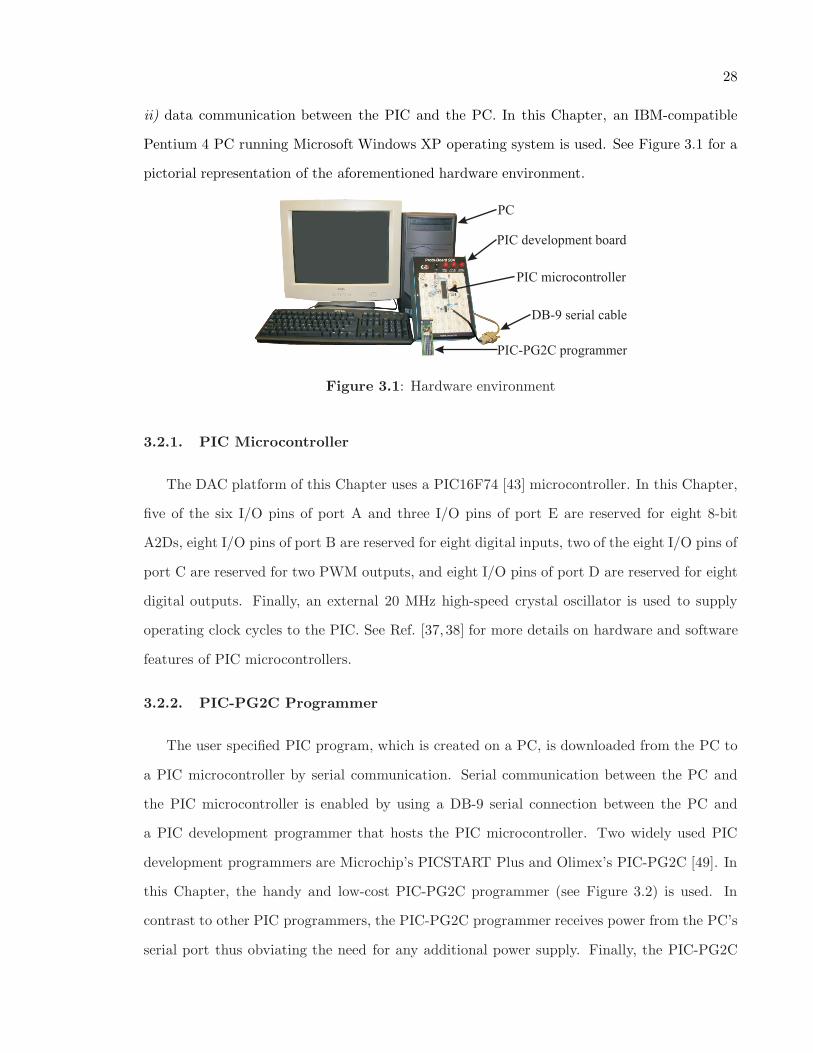
this Chapter, the handy and low-cost PIC-PG2C programmer (see Figure 3.2) is used. In
contrast to other PIC programmers, the PIC-PG2C programmer receives power from the PC’s
serial port thus obviating the need for any additional power supply. Finally, the PIC-PG2C
29
programmer requires IC-Prog [50], a freely available software, to download PIC HEX code to
the PIC microcontroller. Note that the PIC HEX code is obtained from the PIC assembly
code by using the MPASM assembler [51], also available for free.
(a) (b)
Figure 3.2: (a) PIC-PG2C programmer and a PIC (b) PIC-PG2C programmer with a PICmounted
3.2.3. PIC Development Board
The PIC development board of this Chapter is a modified version from the board discussed
in Chapter 2. It consists of: i) a PIC16F74 microcontroller; ii) a 20MHz crystal oscillator
to supply operating clock cycles to the PIC microcontroller; iii) the RS232 driver/receiver
circuitry for serial data communication with the PC; iv) a DB-9 connector; and v) a bread-
board area for custom circuits and easy connectivity between the PIC microcontroller and
sensors/actuators. As discussed in Chapter 2, the Maxim’s MAX232 IC [41] with five 1µF ca-
pacitors serves as the RS232 driver/receiver for voltage-level transformation between PC-based
and the PIC-based logic.
3.3. Software Environment
The software environment for this Chapter consists of MATLAB version 6.5, Simulink
version 5.0, the PIC assembly language, a newly developed Simulink library for the PIC micro-
controller, MPASM, and IC-Prog. The MATLAB toolbox for the PIC microcontroller consists
of a Simulink library of PIC microcontroller functions such that based on the user selected con-
figuration of individual I/O pins of the PIC microcontroller, Simulink automatically produces
and downloads the proper PIC assembly code to the microcontroller. Moreover, the MATLAB
30
toolbox also allows data communication between the PIC microcontroller and MATLAB. Thus,
the MATLAB toolbox for the PIC microcontroller completely obviates the need to manually
program the PIC microcontroller. Note that the MATLAB toolbox automatically executes
the assembler program MPASM and the download program IC-Prog, both of which usually
require command line execution. See Refs. [51, 52] for details on programming the PIC mi-
crocontroller in command line via serial communication. The MATLAB toolbox for the PIC
microcontrollers has two main components: i) a Simulink model file named Template.mdl and
ii) a block library named PICLibrary.
3.3.1. Template.mdl
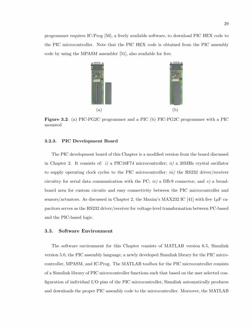
The Template.mdl model file (see Figure 3.3) is a predesigned Simulink model file which
must be used to design Simulink block diagrams for interaction with the PIC microcontroller.
A function named TotalCompile has been embedded within the callback parameters of the
Template.mdl so that the TotalCompile function executes at the beginning of each Simulink
block diagram cycle, before the block diagram actually runs. Details of various tasks performed
by the TotalCompile function are provided in a later subsection. Finally, note that renaming
the Template.mdl file still preserves the callback property embedded in the file, whereas opening
a new Simulink model file does not.
Template.mdl model properties are modified to callthe function at the beginning ofeach Simulink block diagram cycle
TotalCompile
Figure 3.3: Template and model properties
31
3.3.2. PICLibrary
The PICLibrary is a custom library of Simulink blocks (in the form of s-functions) that in-
terface with sensors and actuators connected to the PIC microcontroller. The following blocks
are currently included in the PICLibrary: A2D, PinStateIn, PWM, and PinStateOut. More-
over, the library includes a block labeled IOBlock that is required in all user-designed Simulink
diagrams to enable serial communication between the PIC microcontroller and MATLAB.
Hardware settings and parameter requirements of each block are detailed below.
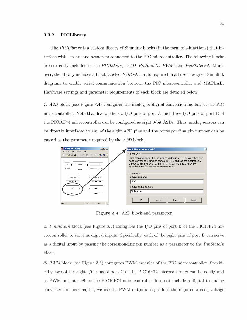
1) A2D block (see Figure 3.4) configures the analog to digital conversion module of the PIC
microcontroller. Note that five of the six I/O pins of port A and three I/O pins of port E of
the PIC16F74 microcontroller can be configured as eight 8-bit A2Ds. Thus, analog sensors can
be directly interfaced to any of the eight A2D pins and the corresponding pin number can be
passed as the parameter required by the A2D block.
Figure 3.4: A2D block and parameter
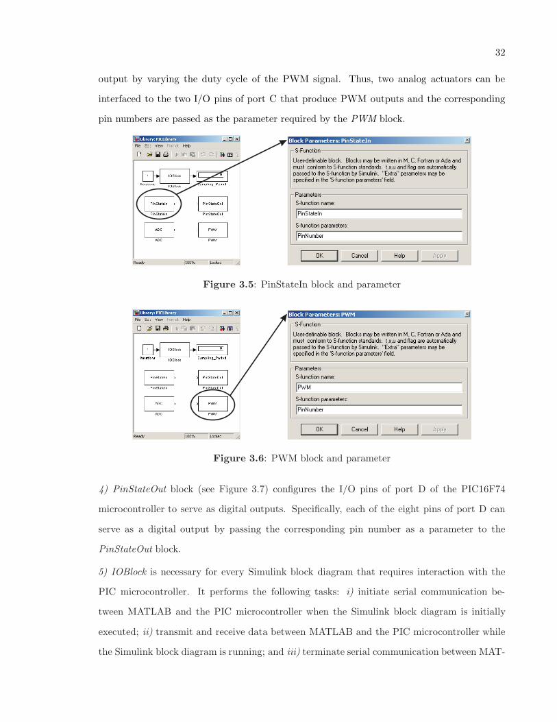
2) PinStateIn block (see Figure 3.5) configures the I/O pins of port B of the PIC16F74 mi-
crocontroller to serve as digital inputs. Specifically, each of the eight pins of port B can serve
as a digital input by passing the corresponding pin number as a parameter to the PinStateIn
block.
3) PWM block (see Figure 3.6) configures PWM modules of the PIC microcontroller. Specifi-
cally, two of the eight I/O pins of port C of the PIC16F74 microcontroller can be configured
as PWM outputs. Since the PIC16F74 microcontroller does not include a digital to analog
converter, in this Chapter, we use the PWM outputs to produce the required analog voltage
32
output by varying the duty cycle of the PWM signal. Thus, two analog actuators can be
interfaced to the two I/O pins of port C that produce PWM outputs and the corresponding
pin numbers are passed as the parameter required by the PWM block.
Figure 3.5: PinStateIn block and parameter
Figure 3.6: PWM block and parameter
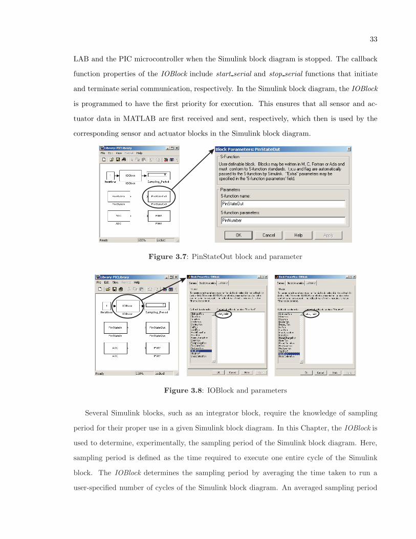
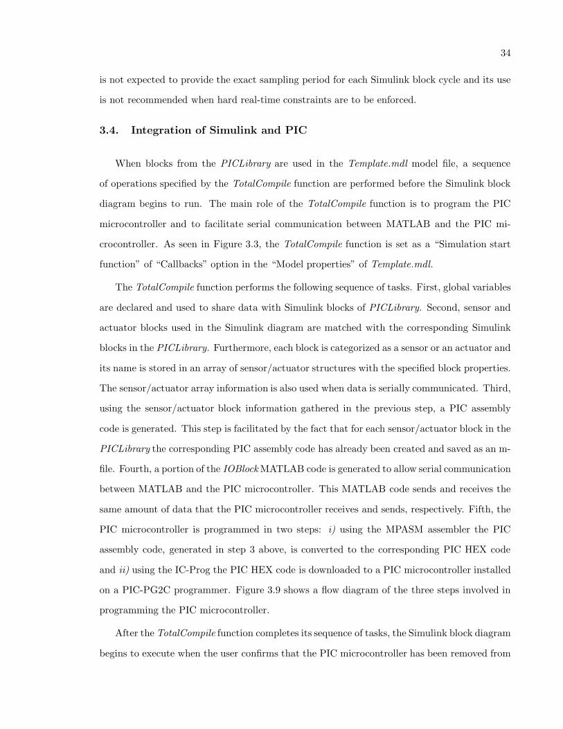
4) PinStateOut block (see Figure 3.7) configures the I/O pins of port D of the PIC16F74
microcontroller to serve as digital outputs. Specifically, each of the eight pins of port D can
serve as a digital output by passing the corresponding pin number as a parameter to the
PinStateOut block.
5) IOBlock is necessary for every Simulink block diagram that requires interaction with the
PIC microcontroller. It performs the following tasks: i) initiate serial communication be-
tween MATLAB and the PIC microcontroller when the Simulink block diagram is initially
executed; ii) transmit and receive data between MATLAB and the PIC microcontroller while
the Simulink block diagram is running; and iii) terminate serial communication between MAT-
33
LAB and the PIC microcontroller when the Simulink block diagram is stopped. The callback
function properties of the IOBlock include start serial and stop serial functions that initiate
and terminate serial communication, respectively. In the Simulink block diagram, the IOBlock
is programmed to have the first priority for execution. This ensures that all sensor and ac-
tuator data in MATLAB are first received and sent, respectively, which then is used by the
corresponding sensor and actuator blocks in the Simulink block diagram.
Figure 3.7: PinStateOut block and parameter
Figure 3.8: IOBlock and parameters
Several Simulink blocks, such as an integrator block, require the knowledge of sampling
period for their proper use in a given Simulink block diagram. In this Chapter, the IOBlock is
used to determine, experimentally, the sampling period of the Simulink block diagram. Here,
sampling period is defined as the time required to execute one entire cycle of the Simulink
block. The IOBlock determines the sampling period by averaging the time taken to run a
user-specified number of cycles of the Simulink block diagram. An averaged sampling period
34
is not expected to provide the exact sampling period for each Simulink block cycle and its use
is not recommended when hard real-time constraints are to be enforced.
3.4. Integration of Simulink and PIC
When blocks from the PICLibrary are used in the Template.mdl model file, a sequence
of operations specified by the TotalCompile function are performed before the Simulink block
diagram begins to run. The main role of the TotalCompile function is to program the PIC
microcontroller and to facilitate serial communication between MATLAB and the PIC mi-
crocontroller. As seen in Figure 3.3, the TotalCompile function is set as a “Simulation start
function” of “Callbacks” option in the “Model properties” of Template.mdl.
The TotalCompile function performs the following sequence of tasks. First, global variables
are declared and used to share data with Simulink blocks of PICLibrary. Second, sensor and
actuator blocks used in the Simulink diagram are matched with the corresponding Simulink
blocks in the PICLibrary. Furthermore, each block is categorized as a sensor or an actuator and
its name is stored in an array of sensor/actuator structures with the specified block properties.
The sensor/actuator array information is also used when data is serially communicated. Third,
using the sensor/actuator block information gathered in the previous step, a PIC assembly
code is generated. This step is facilitated by the fact that for each sensor/actuator block in the
PICLibrary the corresponding PIC assembly code has already been created and saved as an m-
file. Fourth, a portion of the IOBlock MATLAB code is generated to allow serial communication
between MATLAB and the PIC microcontroller. This MATLAB code sends and receives the
same amount of data that the PIC microcontroller receives and sends, respectively. Fifth, the
PIC microcontroller is programmed in two steps: i) using the MPASM assembler the PIC
assembly code, generated in step 3 above, is converted to the corresponding PIC HEX code
and ii) using the IC-Prog the PIC HEX code is downloaded to a PIC microcontroller installed
on a PIC-PG2C programmer. Figure 3.9 shows a flow diagram of the three steps involved in
programming the PIC microcontroller.
After the TotalCompile function completes its sequence of tasks, the Simulink block diagram
begins to execute when the user confirms that the PIC microcontroller has been removed from

35
PIC assembly code isgenerated by TotalCompile
PIC assembly code is convertedto by MPASMPIC HEX code
PIC HEX code is downloadedby IC-Prog via the serial port
Figure 3.9: Flow diagram of programming the PIC microcontroller
the PIC-PG2C programmer and properly installed onto the PIC development board. At this
stage, serial communication between the PIC microcontroller and MATLAB also begins. If
Simulink is stopped and needs to be run again, without any changes to the configuration of
the PIC microcontroller I/O pins, then the PIC microcontroller need not be reprogrammed.
Once the Simulink block diagram begins to execute, the PIC and PC exchange sensory
feedback and actuator commands via serial data communication. Specifically, special function
8-bit PIC registers are used for the serial communication of sensor/actuator data [43,47]. The
IOBlock receives/transmits data from/to the PIC and stores the data in sensor/actuator global
variables.
3.5. Example—DC Motor Control
To illustrate the functionality and capability of the DAC hardware and software of this
Chapter, position control of a DC motor is performed. Specifically, a DC motor test-bed is
interfaced with a PIC-based DAC board and a control algorithm is implemented using Simulink
and the MATLAB toolbox for the PIC microcontroller. The DC motor test-bed, shown in
Figure 3.10, consists of an armature controlled DC motor, instrumented with a continuous
rotation potentiometer, and a power module.
The potentiometer output is used to obtain the necessary feedback signals and to provide
a real-time display of the angular position of the motor. To control the angular position of the
DC motor, the PIC microcontroller applies a controlled voltage signal produced by a control
algorithm running on Simulink.
36
Digitized sensor datafrom PIC
Control outputfrom Simulink
Analog sensor data
Analog control output
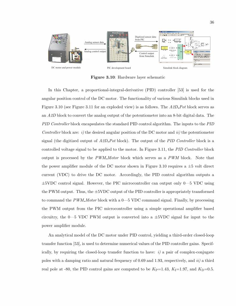
DC motor and power module PIC development board Simulink block diagram
Figure 3.10: Hardware layer schematic
In this Chapter, a proportional-integral-derivative (PID) controller [53] is used for the
angular position control of the DC motor. The functionality of various Simulink blocks used in
Figure 3.10 (see Figure 3.11 for an exploded view) is as follows. The A2D Pot block serves as
an A2D block to convert the analog output of the potentiometer into an 8-bit digital data. The
PID Controller block encapsulates the standard PID control algorithm. The inputs to the PID
Controller block are: i) the desired angular position of the DC motor and ii) the potentiometer
signal (the digitized output of A2D Pot block). The output of the PID Controller block is a
controlled voltage signal to be applied to the motor. In Figure 3.11, the PID Controller block
output is processed by the PWM Motor block which serves as a PWM block. Note that
the power amplifier module of the DC motor shown in Figure 3.10 requires a ±5 volt direct
current (VDC) to drive the DC motor. Accordingly, the PID control algorithm outputs a
±5VDC control signal. However, the PIC microcontroller can output only 0—5 VDC using
the PWM output. Thus, the ±5VDC output of the PID controller is appropriately transformed
to command the PWM Motor block with a 0—5 VDC command signal. Finally, by processing
the PWM output from the PIC microcontroller using a simple operational amplifier based
circuitry, the 0—5 VDC PWM output is converted into a ±5VDC signal for input to the
power amplifier module.
An analytical model of the DC motor under PID control, yielding a third-order closed-loop
transfer function [53], is used to determine numerical values of the PID controller gains. Specif-
ically, by requiring the closed-loop transfer function to have: i) a pair of complex-conjugate
poles with a damping ratio and natural frequency of 0.69 and 1.93, respectively, and ii) a third
real pole at -80, the PID control gains are computed to be KP=1.43, KI=1.97, and KD=0.5.
37
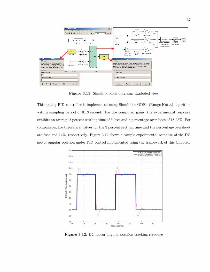
Figure 3.11: Simulink block diagram: Exploded view
This analog PID controller is implemented using Simulink’s ODE4 (Runge-Kutta) algorithm
with a sampling period of 0.13 second. For the computed gains, the experimental response
exhibits an average 2 percent settling time of 5.9sec and a percentage overshoot of 18.25%. For
comparison, the theoretical values for the 2 percent settling time and the percentage overshoot
are 3sec and 14%, respectively. Figure 3.12 shows a sample experimental response of the DC
motor angular position under PID control implemented using the framework of this Chapter.
Figure 3.12: DC motor angular position tracking response

38
3.6. Conclusion
This Chapter provided an overview of a low-cost DAC toolbox that consists of the newly
developed Simulink library for PIC microcontrollers. Serial communication capabilities of
the PIC microcontroller and MATLAB allowed programming of the PIC microcontroller from
MATLAB and exchange of sensory data and actuation signals between the PIC microcontroller
and MATLAB. The capabilities of this low-cost DAC system were illustrated through a DC
motor angular position control experiment.