chapter 5 networking hardware network+ guide to networks, fourth edition
TRANSCRIPT
Chapter 5
Networking Hardware
Network+ Guide to Networks, Fourth Edition

Objectives
• Identify the functions of LAN connectivity hardware• Install and configure a NIC (network interface card)• Identify problems associated with connectivity
hardware• Describe the factors involved in choosing a NIC,
hub, switch, or router• Discuss the functions of repeaters, hubs, bridges,
switches, routers, and gateways, and the OSI Model layers at which they operate
• Describe the use and types of routing protocols
NICs (Network Interface Cards)
• Connectivity devices that enable workstations, servers, printers, or other nodes to receive and transmit data over network media– Usually contain data transceiver
– Belong to Physical and Data Link layers
– Apply data signals to wire
– Assemble and disassemble data frames
– Interpret physical addressing information
– Determine which node has right to transmit data at any given instant

Types of NICs
• NICs come in variety of types depending on:– Access method
– Network transmission speed
– Connector interfaces
– Type of compatible motherboard or device
– Manufacturer

Internal Bus Standards
• Bus: circuit used by motherboard to transmit data to computer’s components– Including memory, processor, hard disk, and NIC– Capacity defined principally by:
• Width of data path (number of bits that can be transmitted in parallel)
• Clock speed
• Expansion slots allow devices to connect to computer’s expanded bus– Devices found on circuit board called an expansion card

Peripheral Bus Standards (continued)
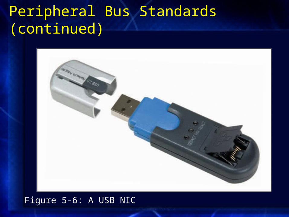
• USB: standard interface used to connect multiple types of peripherals– USB 1.1 and USB 2.0
• FireWire: codified by IEEE as IEEE 1394– Can be used to connect many types of peripherals
– Can connect computers on a small network
– 4-pin and 6-pin connectors
• CompactFlash: most likely found connecting devices too small to handle PCMCIA slots
Peripheral Bus Standards (continued)
Figure 5-6: A USB NIC
On-board NICs
• Some peripheral devices connect directly to motherboard using on-board ports– e.g., a mouse
• Many new computers use on-board NICs– Integrated into motherboard
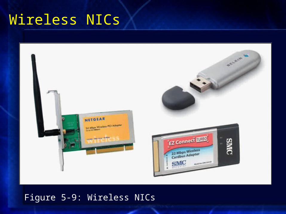
Wireless NICs
Figure 5-9: Wireless NICs

Installing NICs
• First install hardware, then software– May have to configure firmware
• Set of data or instructions saved to a ROM [electrically erasable programmable read-only memory (EEPROM)]
• Always read manufacturer’s documentation and follow proper safety procedures
• Multiple NICs may be installed• Jumper: plastic piece with metal receptacle• Dual inline package (DIP) switch indicates
parameter setting
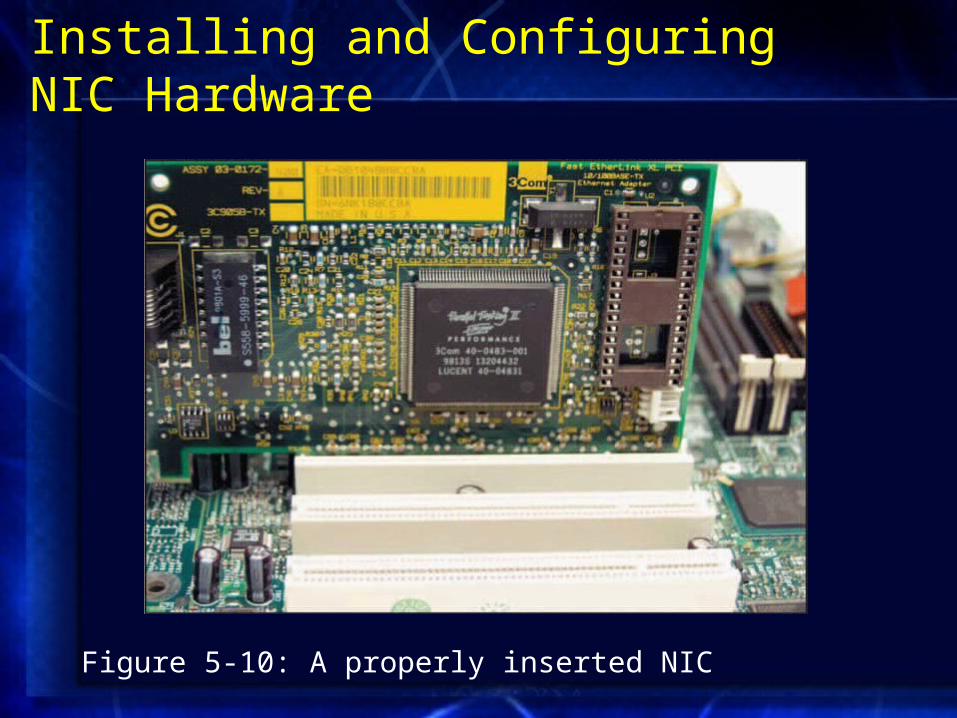
Installing and Configuring NIC Hardware
Figure 5-10: A properly inserted NIC

Installing and Configuring NIC Hardware (continued)
Figure 5-11: Installing a PCMCIA-standard NIC
Installing and Configuring NIC Software
• Device driver: software enabling attached device to communicate with computer’s OS– Must ensure that correct device driver installed and
configured properly for the NIC
• To install from Windows XP interface, need Windows XP software and NIC’s device drivers– Can usually download NIC software from manufacturer’s
Web site
• Installing NIC drivers on UNIX or Linux depends somewhat on OS version
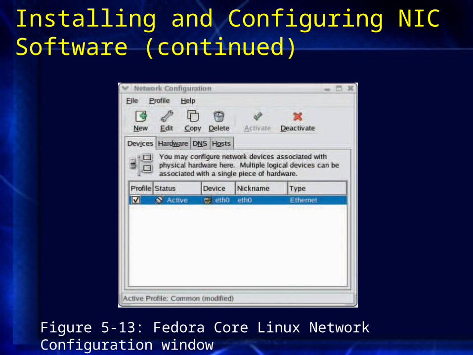
Installing and Configuring NIC Software (continued)
Figure 5-13: Fedora Core Linux Network Configuration window
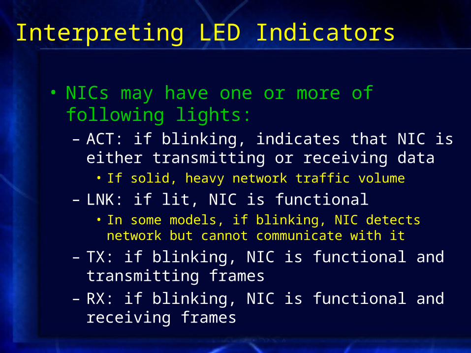
Interpreting LED Indicators
• NICs may have one or more of following lights:– ACT: if blinking, indicates that NIC is either transmitting
or receiving data• If solid, heavy network traffic volume
– LNK: if lit, NIC is functional• In some models, if blinking, NIC detects network but cannot
communicate with it
– TX: if blinking, NIC is functional and transmitting frames
– RX: if blinking, NIC is functional and receiving frames

IRQ (Interrupt Request)
• Message to computer instructing it to stop what it is doing and pay attention to something else
• Interrupt: circuit board wire over which device issues voltage to signal IRQ
• IRQ number: means by which bus understands which device to acknowledge– Range from 0 to 15

IRQ (continued)
• Symptoms possibly indicating two devices attempting to use same IRQ:– Computer locks up either upon starting or when OS is
loading
– Computer runs much more slowly than usual
– Devices such as USB or parallel ports stop working
– Video or sound card problems
– Computer fails to connect to network
– Intermittent data errors during transmission

IRQ (continued)
• If IRQ conflicts occur, must reassign device’s IRQ– Through OS
– Through adapter’s EEPROM configuration utility or computer’s CMOS configuration utility
• Complementary metal oxide semiconductor (CMOS): microchip that stores settings pertaining to computer’s devices
• Basic input/output system (BIOS): instructions enabling computer to initially recognize hardware

Memory Range
• Indicates area of memory that NIC and CPU use for exchanging (buffering) data– Hexadecimal notation
• Some memory ranges reserved for specific devices• NICs typically use memory range in high memory
area– A0000–FFFFF
– Some manufacturers prefer certain ranges

Base I/O Port
• Specifies area of memory that will act as channel for moving data between NIC and CPU– Hexadecimal notation
– Device’s base I/O port cannot be used by any other device
• Most NICs use two memory ranges for this channel– Base I/O port settings identify beginning of each range
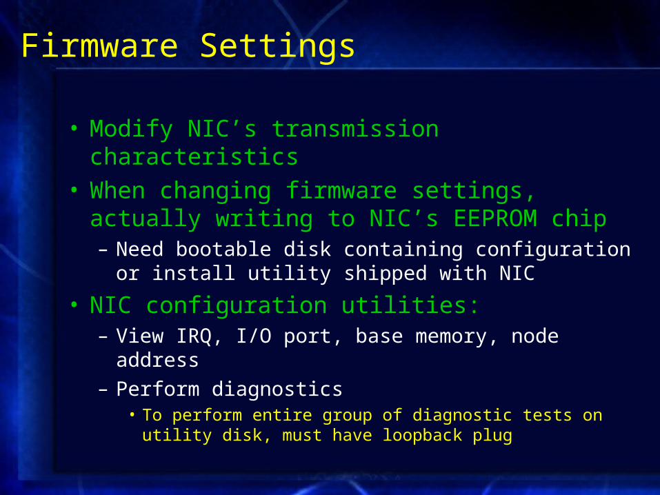
Firmware Settings
• Modify NIC’s transmission characteristics• When changing firmware settings, actually writing
to NIC’s EEPROM chip– Need bootable disk containing configuration or install
utility shipped with NIC
• NIC configuration utilities:– View IRQ, I/O port, base memory, node address
– Perform diagnostics• To perform entire group of diagnostic tests on utility disk, must
have loopback plug

Choosing the Right NIC
Table 5-2: NIC characteristics
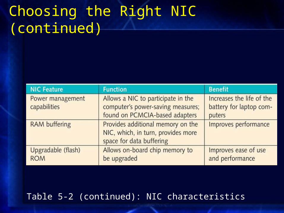
Choosing the Right NIC (continued)
Table 5-2 (continued): NIC characteristics
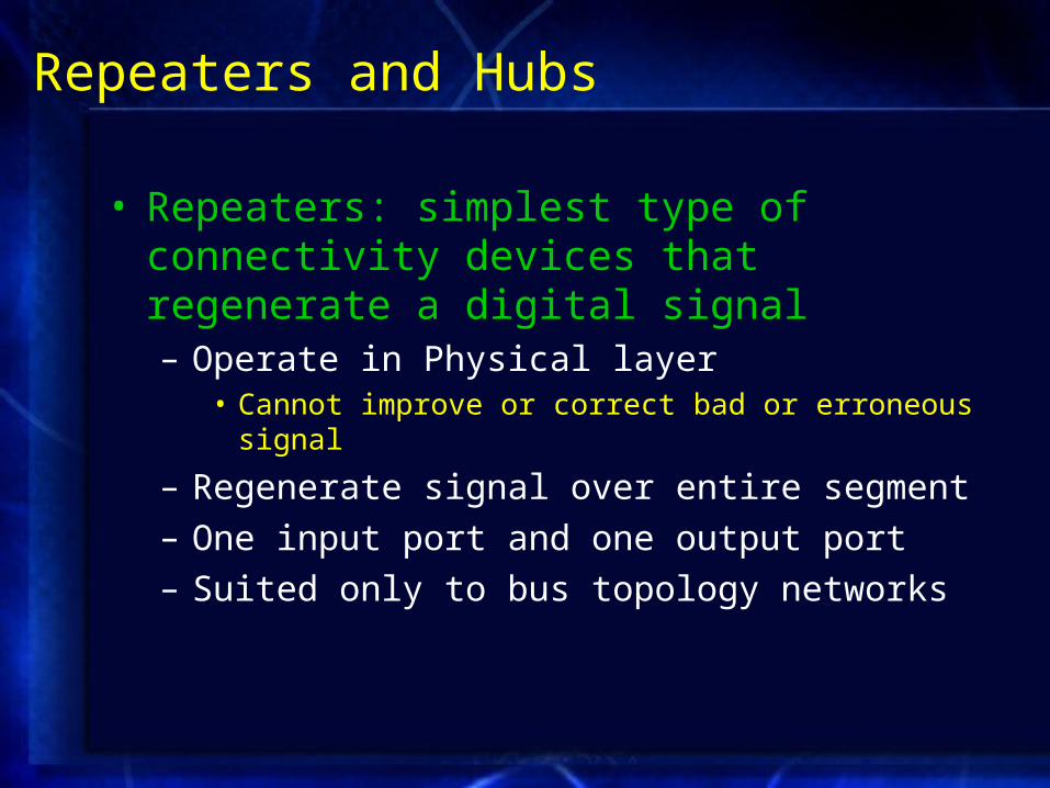
Repeaters and Hubs
• Repeaters: simplest type of connectivity devices that regenerate a digital signal– Operate in Physical layer
• Cannot improve or correct bad or erroneous signal
– Regenerate signal over entire segment
– One input port and one output port
– Suited only to bus topology networks
Repeaters and Hubs (continued)
• Hub: repeater with more than one output port– Multiple data ports
– Operate at Physical layer
– Uplink port: allows connection to another hub or other connectivity device
– On Ethernet networks, can serve as central connection point of star or star-based hybrid topology
– On Token Ring networks, hubs are called Multistation Access Units (MAUs)
Repeaters and Hubs (continued)
• Hubs (continued):– Connected devices share same amount of bandwidth and
same collision domain• Logically or physically distinct Ethernet network segment on
which all participating devices must detect and accommodate data collisions
• Types of hubs:– Passive– Intelligent– Standalone– Stackable

Bridges
• Connect two network segments – Analyze incoming frames
• Make decisions about where to direct them based on each frame’s MAC address
– Operate at Data Link layer
– Protocol independent• Can move data more rapidly than traditional routers
– Extend Ethernet network without extending collision domain or segment
– Can be programmed to filter out certain types of frames
Switches
• Subdivide network into smaller logical pieces (segments)– Can operate at levels 2, 3, or 4 of OSI model
– Multiport bridges
– Most have internal processor, OS, memory, and several ports
• Each port on switch acts like bridge• Each connected device effectively receives own
dedicated channel

Cut-Through Mode
• Switch running in cut-through mode reads frame’s header and decides where to forward the data before receiving the entire packet– Cannot read FCS before transmission
• Cannot detect corrupt packets
– Can detect runts• Erroneously shortened packets
– Biggest advantage is speed
Store and Forward Mode
• Switch reads entire data frame into memory and checks for accuracy before transmitting– Transmits data more accurately
– Slower than cut-through mode
– Can transfer data between segments running different transmission speeds
Using Switches to Create VLANs
• Virtual LANs (VLANs) logically separate networks within networks
• Use switches to group a number of ports into a broadcast domain– Combination of ports making up a Layer 2 segment
• In TCP/IP, referred to as a subnet
• VLANs created by properly configuring switch’s software
• VLAN configuration requires careful planning
Higher-Layer Switches
• Layer 3 switches (routing switch) and Layer 4 switches
• Ability to interpret higher-layer data enables switches to perform advanced filtering, statistics keeping, and security functions
Routers
• Multiport connectivity devices that direct data between nodes on a network– Can integrate LANs and WANs
• Running at different transmission speeds • Using variety of protocols
– Reads incoming packet’s logical addressing information• Determines where to deliver packet • Determines shortest path to that network
– Operate at Network layer– Protocol-dependent
Router Features and Functions
• Typical router has internal processor, OS, memory, various input and output jacks, and management console interface
• Modular router: multiple slots to hold different interface cards or other devices
• All routers can:– Connect dissimilar networks
– Interpret Layer 3 addressing and other information
– Determine the best path for data to follow
– Reroute traffic

Router Features and Functions (continued)
• Other router functions:– Filter out broadcast transmissions
– Prevent certain types of traffic from getting to a network
– Support simultaneous local and remote connectivity
– Provide high network fault tolerance through redundant components
– Monitor network traffic and report statistics
– Diagnose internal or other connectivity problems

Router Features and Functions (continued)
• Interior router directs data between nodes on autonomous LANs
• Exterior router directs data between nodes external to given autonomous LAN
• Border routers connect autonomous LAN with a WAN
• Static routing: network administrator programs router to use specific paths between nodes
• Dynamic routing automatically calculates best path between two nodes – Accumulates information in routing table
Router Features and Functions (continued)
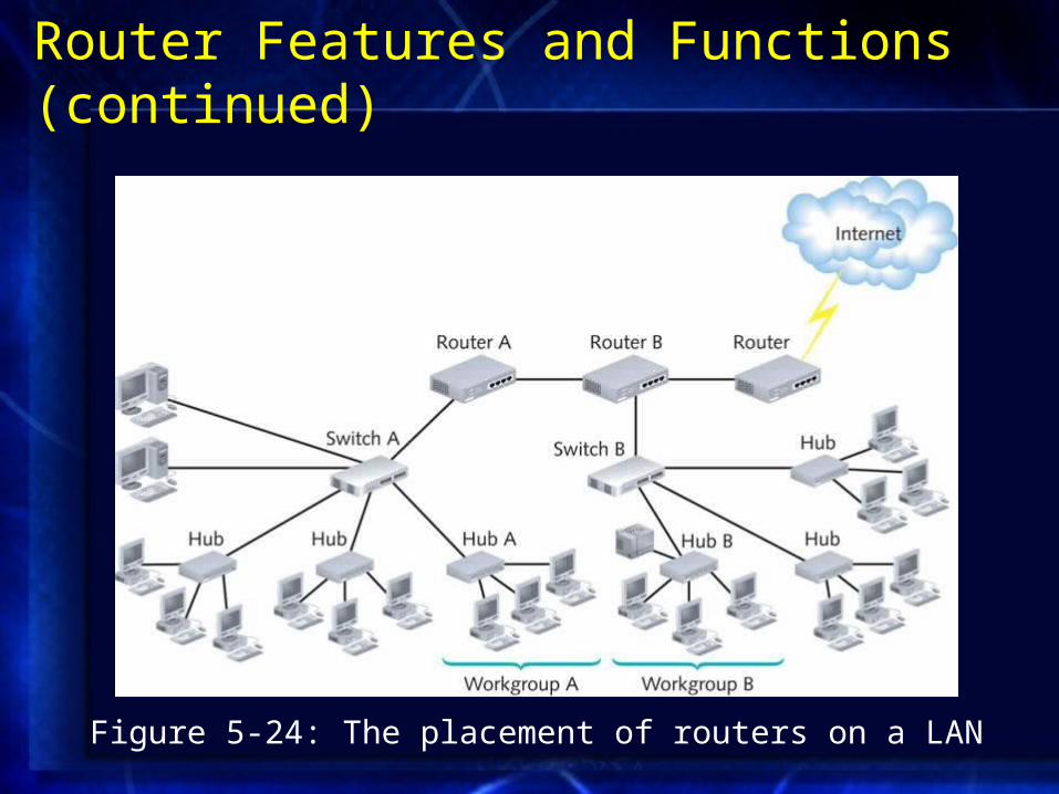
Figure 5-24: The placement of routers on a LAN
Routing Protocols: RIP, OSPF, EIGRP and BGP
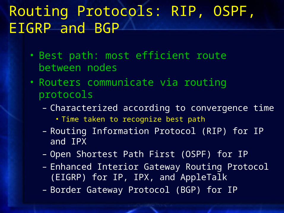
• Best path: most efficient route between nodes• Routers communicate via routing protocols
– Characterized according to convergence time• Time taken to recognize best path
– Routing Information Protocol (RIP) for IP and IPX
– Open Shortest Path First (OSPF) for IP
– Enhanced Interior Gateway Routing Protocol (EIGRP) for IP, IPX, and AppleTalk
– Border Gateway Protocol (BGP) for IP
Brouters
• Bridge routers• Routers that take on some characteristics of bridges
– Can forward nonroutable protocols
– Connect multiple network types through one device

Gateways
• Connect two systems using different formatting, communications protocols, or architecture– Repackage information to be read by another system
• Operates at multiple OSI Model layers
– E-mail gateway
– Internet gateway
– LAN gateway
– Voice/data gateway
– Firewall
Summary
• Network adapters come in a variety of types depending on access method, network transmission speed, connector interfaces, type of compatible motherboard, and manufacturer
• Desktops or tower PCs may use an expansion card NIC, which must match the system’s bus
• NICs are designed to be used with either wire-bound or wireless connections
• Firmware combines hardware and software• Repeaters are the connectivity devices that perform
the regeneration of a digital signal
Summary (continued)
• A hub contains multiple data ports into which the patch cables for network nodes are connected
• Bridges resemble repeaters in that they have a single input and a single output port, but they can interpret the data they retransmit
• As nodes transmit data through a bridge, the bridge establishes a filtering database
• Switches subdivide a network into smaller, logical pieces
Summary (continued)
• A router is a multiport device that can connect dissimilar LANs and WANs running at different transmission speeds, using a variety of protocols
• Routers are protocol-dependent• Routing protocols provide rules for communication
between routers and help them determine the best path between two nodes
• Gateways are combinations of networking hardware and software that connect two dissimilar kinds of networks