chapter 8 construction procedures · chapter 8 construction procedures the success of streambank...
TRANSCRIPT

CHAPTER 8
CONSTRUCTION PROCEDURES
The success of streambank protection and sta-bilization projects hinges on selecting appropriatemethods, functional design, and on-site supervi-sion during construction by experienced person-nel. Proper installation and quality control is criti-cal to project success. This chapter describes con-struction procedures and practices for bank stabi-lization projects to help ensure that project objec-tives are met.
8.1 GENERAL CONSTRUCTIONPLANNING
8.1.1 CONSTRUCTION SUPERVISION
Because many general contractors have littleknowledge and experience with vegetative meth-ods, it is important to have experienced personnelon-site for construction management. The basicduty of the construction manager is to ensure thatproject specifications for handling, preparing andinstalling plant and other materials are followed,and that the specified structures are constructed asdesigned. Supervisor(s) should be on site everyday to resolve problems with materials, necessarydesign changes, and other unforseen difficulties.They should also keep detailed records aboutmaterials used, costs, work performed daily byeach crew, percent project completion, and adher-ence to schedule. These records provide data onthe quantities of material used and work per-formed, difficulties encountered, and other impor-tant information for designing and estimating costsof future projects. Post-project monitoring recordsshould also include cost of and time required formonitoring, replacement of dead plants, and othernecessary maintenance.
Qualifications for supervisory personnelshould include experience with installing the speci-fied material and structures, including vegetativemethods, knowledge of proper handling and plant-
ing requirements of the various plant species. Toattain project quality control, site supervisorsshould ensure that the following tasks are com-pleted.
Prior to start of construction:
• Contact the construction superintendent orcrew foreman and arrange for a visit of theproject site. Discuss each aspect of theproject and construction area work limitswith contractor. Review erosion andsediment control requirements withcontractor.
• Obtain copies of needed plans, permits andeasements. All permits must be availablefor review on the project site.
• Schedule and hold a pre-constructionconference with inspectors responsible forpermit compliance. All contractors shouldalso attend this meeting.
• Contact and inform property owners in theproject area of the upcoming project. Secureconstruction access where needed.
• Contact a utility location service to identifyunderground utilities and mark the locationin the field.
• Delineate areas within the project site thatrequire special attention.
• Identify vegetation to be preserved on theconstruction site, and specify preservationmethods. Prevent grade changes (eitheraddition or removal of soil) within thedriplines of trees to be preserved.
• Erect barriers around areas to be protected,vegetation to be salvaged, and the driplinesof trees to be saved to prevent operation ofheavy equipment in these areas.
• When vegetative methods are specified,verify location and condition of source sitesfor harvesting plant materials.
• Arrange for and implement constructionstaking.
Construction Procedures 8-1

• Ensure that construction materials (e.g.,soil, vegetation, rock) meet project specifica-tions.
• Verify that designs match actual groundconditions.
At the start of construction:
• Check the initial site preparation (i.e. gradingand shaping) for consistency with the projectplans.
• Verify the layout of each specifiedstabilization method.
During construction:
• Contact regulatory agencies as needed tofacilitate required site inspections.
• Coordinate the delivery (timing) of variousmaterials such as rock, vegetation and soil.This material should be delivered in properamounts and sequence to avoid constructiondelays or degradation of vegetation.
• Stockpile construction materials in properamounts and sequence in areas close to thework area. Most construction sites havelimited working space and staging areas,most of which may lie at the edge of astreambank. These areas need to be clearfor equipment to operate and to avoidconstruction delays and waste in moving ordriving over construction materials.
• Ensure that the location and dimensions ofspecified excavations are as specified.
• When harvesting, handling and preparingplant materials:a. Ensure that fresh cuttings arrive at the
project site each day and that unusedmaterial is properly stored for use thenext day.
b. Inspect the storage area daily when itis in use to ensure that all unaccept-able plant material is removed fromthe construction site and that only vi-able materials are installed.
c. Ensure that invasive plant materialsare not brought to the site.
• Ensure correct placement and orientationof cuttings, stakes, and branches invegetative methods.
• Ensure all materials delivered to the site(soil, plants, rock) are of acceptable quality.
• Ensure that soil compaction occursaccording to specification.
• If specified, make sure that fertilizerapplication and soil conditioning occurs.
• Ensure that necessary staking, pruning andcutting of vegetation occurs as specified.
8.1.2 MINIMIZING SITE DISTURBANCESDURING CONSTRUCTION
In general, the less disturbance to the naturalsystem, the greater the environmental benefits.Thus, disturbance of the stream/river and its ripar-ian corridor should be minimized during construc-tion. Construction damages can be limited by:
• Installing erosion control measures as earlyas possible to minimize damages fromsedimentation.
• Using small equipment and hand laborwhenever feasible.
• Limiting site access to as few locations aspossible.
• Locating staging areas away from allsensitive areas and their buffers.
• Avoiding construction during critical timessuch as spawning or nesting periods.
• Minimizing or avoiding extensive gradingand earthwork in sensitive areas.
• Retaining natural vegetation wheneverpossible.
• When vegetation must be removed, limitingthe exposure of disturbed soil to the smallestpractical area and time.
• For vegetation that will be saved, limitingroot exposure to the shortest possible time.Remove and store in a temporary nursery orholding area any existing woody vegetationthat might be useful later in the project.
• Stockpiling and protecting topsoil removedduring grading operations so that it can bereused.
Construction Procedures8-2

• Protecting sensitive areas exposed duringconstruction with temporary vegetationand/or mulch.
• Managing runoff and excess groundwaterto minimize erosion and slope failure.
8.1.3 SITE PREPARATION
Site preparation are those activities which oc-cur immediately prior to the beginning of projectconstruction. This includes such activities as iden-tifying and visibly marking clearing limits, install-ing temporary erosion/sedimentation control mea-sures, placing construction fencing around areasto be protected, and installing construction drain-age if necessary.
All earthwork activities (i.e., shaping and grad-ing of banks, removal and disposal of excessmaterials, stockpiling of soil and other activities)should occur in accordance with plan specifica-tions and applicable regulations. Close coordina-tion between the crews installing the erosion andsediment controls and those preforming theearthwork activities is vital for minimizing ad-verse effects to water quality.
Sites that are wet and poorly drained requireextra preparation. At sites with extremely wet soilconditions, it may be necessary to prevent lossesof both plants and equipment by providing load-bearing mats from where equipment can be safelyoperated. If the moisture is from surface water orshallow groundwater, a French drain or otherdrain may be needed to intercept the flow. In somecases, drains can be incorporated in the structure.A geotechnical expert should be consulted if drain-age problems exist.
If needed, the physical properties of the soilcan sometimes be altered by adding organic mate-rial such as commercial compost, sand, silt, or clayand mechanical mixing. Adding sand to wet claysoils can be extremely difficult as the clay portionsoften stick together rather than mixing. Althoughfrequently recommended, this process is seldomsuccessful in improving soil conditions.
8.1.4 LABOR NEEDS
Vegetative stabilization methods are often la-bor intensive. Two crews are needed for mostmedium to large projects: one for harvesting plantmaterials and one for installation. The number ofcrew members will vary with the project. Twopeople per crew is generally adequate for smallprojects. On small projects or where the plantmaterial is close by, one crew can both harvest andinstall plant material as work progresses. On largerprojects, crews should coordinate closely to pre-vent having excess material on site which mayresult in installation delays.
Unskilled labor can be used if supervised by anexperienced crew leader. Because training re-quirements are minimal, training can usually beaccomplished on site in a few days. Some meth-ods, such as constructing fascines, can be com-pleted by individuals who are physically or devel-opmentally challenged, thus providing employ-ment opportunities for these diverse groups. Localand state conservation corps may also be a sourceof labor. Chamberlain (1986) reported excellentsuccess in revegetation projects along the CedarRiver using labor recruited through the Washing-ton State Conservation Corps. The WashingtonState Departments of Natural Resources and Fish-eries have used correctional inmates on someprojects (L. Cowan, Wash. Dept. Fish., per. comm.,1992).
8.2 CONSTRUCTION PLANNINGFOR VEGETATIVE METHODS
8.2.1 ACQUISITION OF PLANT MATERIAL
Live Cuttings
Live cuttings are normally collected from ex-isting, healthy, native vegetation. Local nativeplants are generally resistant to disease and arebetter adapted to local conditions than plants fromdistant sources. Careful observations of donormaterial are required to prevent the introduction of
Construction Procedures 8-3
Construction Procedures8-4
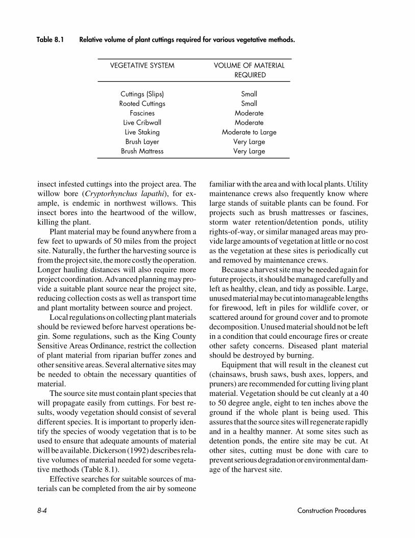
Table 8.1 Relative volume of plant cuttings required for various vegetative methods.
VEGETATIVE SYSTEM VOLUME OF MATERIAL REQUIRED
Cuttings (Slips) SmallRooted Cuttings Small
Fascines ModerateLive Cribwall ModerateLive Staking Moderate to LargeBrush Layer Very Large
Brush Mattress Very Large
insect infested cuttings into the project area. Thewillow bore (Cryptorhynchus lapathi), for ex-ample, is endemic in northwest willows. Thisinsect bores into the heartwood of the willow,killing the plant.
Plant material may be found anywhere from afew feet to upwards of 50 miles from the projectsite. Naturally, the further the harvesting source isfrom the project site, the more costly the operation.Longer hauling distances will also require moreproject coordination. Advanced planning may pro-vide a suitable plant source near the project site,reducing collection costs as well as transport timeand plant mortality between source and project.
Local regulations on collecting plant materialsshould be reviewed before harvest operations be-gin. Some regulations, such as the King CountySensitive Areas Ordinance, restrict the collectionof plant material from riparian buffer zones andother sensitive areas. Several alternative sites maybe needed to obtain the necessary quantities ofmaterial.
The source site must contain plant species thatwill propagate easily from cuttings. For best re-sults, woody vegetation should consist of severaldifferent species. It is important to properly iden-tify the species of woody vegetation that is to beused to ensure that adequate amounts of materialwill be available. Dickerson (1992) describes rela-tive volumes of material needed for some vegeta-tive methods (Table 8.1).
Effective searches for suitable sources of ma-terials can be completed from the air by someone
familiar with the area and with local plants. Utilitymaintenance crews also frequently know wherelarge stands of suitable plants can be found. Forprojects such as brush mattresses or fascines,storm water retention/detention ponds, utilityrights-of-way, or similar managed areas may pro-vide large amounts of vegetation at little or no costas the vegetation at these sites is periodically cutand removed by maintenance crews.
Because a harvest site may be needed again forfuture projects, it should be managed carefully andleft as healthy, clean, and tidy as possible. Large,unused material may be cut into manageable lengthsfor firewood, left in piles for wildlife cover, orscattered around for ground cover and to promotedecomposition. Unused material should not be leftin a condition that could encourage fires or createother safety concerns. Diseased plant materialshould be destroyed by burning.
Equipment that will result in the cleanest cut(chainsaws, brush saws, bush axes, loppers, andpruners) are recommended for cutting living plantmaterial. Vegetation should be cut cleanly at a 40to 50 degree angle, eight to ten inches above theground if the whole plant is being used. Thisassures that the source sites will regenerate rapidlyand in a healthy manner. At some sites such asdetention ponds, the entire site may be cut. Atother sites, cutting must be done with care toprevent serious degradation or environmental dam-age of the harvest site.

Rooted stock
Nursery stock should be ordered well in ad-vance of planting dates to ensure sufficient quan-tity and quality of the desired species. Becausethere is still a relatively small demand for nativeplant stock, only limited stock is available eachyear. For large projects with sufficient lead time,contract growing can eliminate this problem bystarting cuttings and seeds anywhere from a fewweeks to several months or even years in advance.
If the desired plant species are not available,carefully review plant substitutions suggested bynursery staff. The definition of “native plant”varies widely among horticulture, landscaping,and nursery professionals. Often, nursery stockincludes species that simply grow well in theregion or is related to the specified native species.
There are numerous commercial sources ofplants and plant information. Infonet (1992) pro-duces a monthly listing of stock availability, prices,and size for many nurseries in the Pacific North-west. Shank (1991) provides a list of Pacific North-west nurseries that produce native species.Baumgartner et al. (1991) provide information onsources, selection, planting, and care of trees.Table 8.2 lists local growers of native plants.Ideally, the best nursery stock for river projects isfrom local nurseries, i.e., those located within thesame major drainage basin as the project site.
8.2.2 FACTORS AFFECTING PLANTCOSTS
The cost of plant material reflects the time andeffort required to produce the plant. As such, smallplants are usually less expensive than larger plantsof the same species. Fast-growing, easily propa-gated, relatively pest-free species tend to be lessexpensive and more readily available. Because thecost per plant increases with small productionquantities, even an easily propagated species canbe expensive if there is limited demand.
Some nurseries may offer discounts for largeorders or contract-produced material on a case-by-case basis. Contract growing is recommended if
large amounts of rooted stock will be needed, as itallows ample time to produce good quality stock.
The commercial availability of rooted stockvaries seasonally as do the species and manner inwhich they are available. During the winter months,bare-root, single-tubed or balled and burlappedplants are generally available and less expensive.After April, most nurseries put plants into contain-ers, though some nurseries will provide field plantson demand.
The choice of stock type used (balled andburlapped, bare root, containerized, cuttings orlive stakes, rooted cuttings, seed mixes) will bedefined by the anticipated site conditions. Theseinclude river characteristics (e.g., frequency andduration of inundation), soil conditions, control ofcompeting vegetation, and the type of structure tobe installed. If competition from grasses or shrubsmay be a problem, larger plants or cuttings shouldbe used.
The quality of the plant material is very impor-tant for long-term survival. If possible, order plantsgrown from seed collected from the same geo-graphic area and elevation as the planting site.Most growers have this information available.Often, these plants will be better adapted to cli-matic conditions of the site than plants from moredistant regions.
8.2.3 INSTALLATION TIMING FORVEGETATIVE METHODS
For maximum success, streambank stabiliza-tion projects should be installed while plants aredormant (Schiechtl 1980; Adams 1982; Baum-gartner et al. 1991). Once buds break and leavesbegin to expand, plant survival rates decreasemarkedly. Fully-leafed plants may have survivalrates of five to ten percent or less. Installationsshould coincide with cool, moist but not exces-sively wet weather in either spring (late Februaryto April) or fall (October to mid-December). Ifhigh flows are not anticipated against a recon-structed bank, fall is the best time to plant becausesubstantial root growth can occur during the win-ter. Because root growth occurs any time the soilis not frozen, fall planting allows trees, shrubs, and
Construction Procedures 8-5

cuttings to establish better root methods prior tosummer droughts than does spring planting. Springplantings with supplemental irrigation are recom-mended if site conditions are such that a fallinstallation may be removed by high flows. Unlessirrigation is provided, summer installations can bedifficult because of drought stresses that occurwhen plants are cut or transplanted. While accept-able, winter is generally not preferred because of
the difficulty in working wet soil and also becauseof excessive soil compaction can occur.
While vegetative methods are most effectivewhen installed during late fall to early spring, thismay not coincide with the construction windowfor working in King County streams. The con-struction window refers to the period of the yearwhen the Washington Departments of Fisheriesand Wildlife allow instream construction activi-ties. Because it is defined by the presence of
Construction Procedures8-6
Table 8.2. List of local growers and nurseries providing native species in and nearby King County.(Compiledfrom Shank 1991 and Baumgartner et al. 1991.)
Abundant Life Seed Foundation Port Townsend 385-5660Barfod’s Hardy Ferns Bothell 483-0205Cascade Conifers Olympia 754-6827Colvos Creek Farm Seattle 441-1509Fancy Fronds Seattle 284-5332Fir Run Nursery Puyallup 848-4731Frosty Hollow Nursery Langley 221-2332Furney’s Nursery Des Moines 624-0634Hood Canal Nurseries Port Gamble 297-7555IFA Nurseries - Nisqually Olympia 456-5669J. Hofert Forest Nursery Olympia 786-6300King County Conservation District Renton 226-4867Lawyer Nursery Olympia 456-1839Morning Glory Farms Stanwood 629-4831Newstart Nursery Camano Island 629-3751Pacific Natives & Ornamentals Bothell 483-8108Pacific Wetland Nursery Kingston 297-7575Peninsula Gardens Wholesale Gig Harbor 851-8115Silvaseed Company Roy 843-2246Storm Lake Growers Snohomish 794-4842Sweetbriar Nursery Woodinville 821-2222Tissues & Liners Woodinville 885-5050Warm Beach Nursery Stanwood 652-5833Watershed Garden Works Olalla 857-2785Webster Forest Nursery: DNR Olympia 753-5305Wetlands Northwest Graham 846-2774Weyerhaeuser Rochester 273-5527Weyerhaeuser Tacoma 924-2547
The King County Department of Public Works does not endorse any of the above businesses or theirproducts. This list is provided to the reader only as a general service in locating materials described inthis document.

spawning salmonids or incubating eggs, the con-struction window varies from stream to stream.Planting times also vary with weather conditions,elevation, and other site conditions such as soilmoisture.
Several options are available for constructionthat can not coincide with the construction win-dow and yet must occur within the channel. Onsmall sites it may be feasible to isolate the con-struction activity from flowing water with pilebarriers, sand bags, coffer dams, or other means.At other sites, phased construction may be fea-sible. For example, the construction of the struc-tural component, which is most disruptive to thestream, could be completed during the construc-tion window, with the installation of vegetativesystem occurring during the following dormantseason. Phased construction may increase overallproject costs, especially if equipment has to bemoved. Under certain conditions, however, it maybe the most practical or only option available.
Another alternative is to use rooted plantsinstead of live cuttings so that vegetative elementsof the project can be installed during the construc-tion window. This option is generally more expen-sive as nursery stock must be purchased or grown.
In some cases, the construction window can bealtered as much as a week by harvesting materialsat higher elevations where they have either notbroken dormancy (in the spring) or have entereddormancy (in the fall). Generally the differencesin elevation should not exceed 1,000 feet, norshould plants be imported across major watershedboundaries. This helps protect the genetic integ-rity of local plant populations and reduces thechance of introducing disease organisms intohealthy populations.
8.2.4 HANDLING, DELIVERY ANDSTORAGE OF PLANT MATERIALS
Live branch cuttings should be bound securelyinto bundles at the collection site for easy handlingand for protection during transport. During bun-dling, the growing tips should be oriented in thesame direction with side branches and limbs keptintact.
Branch bundles should be placed on the trans-port vehicles in an orderly fashion to preventdamage and facilitate handling. The material shouldbe covered with a tarpaulin during transportationto prevent additional stress from drying. Dampburlap draped over plant materials or placing thecuttings in moist sand will provide additionalhumidity and reduce drying of cut ends. Whilelatex paint is often recommended to seal, and,sometimes can be helpful in identifying the up-right end of live stakes, its use can be very messyand does not seem to appreciably increase plantsurvival.
Plant material should be harvested and deliv-ered to the project site as quickly as possible,especially on warm (more than 50° F), windy, orlow-humidity days. For maximum survival, cutplant material should arrive at the job site withineight hours of cutting. Vegetation for live stakes orother similar use should be used the same day thatit was cut and trimmed. If the air temperature is50°F or higher, all live materials should be in-stalled on the day they are cut. Although notoptimum, material not installed on the day it wascut can be installed later if the air temperature isless than 50°F. Because live plant material oftendeteriorates and is less effective when held forlong periods, all fresh cut plant materials should beused within two days after cutting unless refriger-ated.
Protect all plant material from drying by stor-ing it in shady, moist areas, placing it in fresh wateror in cool storage if it must be stored for severaldays. Outside storage locations should be continu-ally shaded and protected from the wind. Waterused for keeping cuttings or rooted material moistshould be free of substances toxic to the plantssuch as petroleum products or excessive amountsof nutrients.
Plant roots must not be allowed to dry. Expo-sure of root systems to drying agents such as sunor wind is the cause of many planting failures.Desiccation of roots results in the plants effec-tively being unrooted cuttings when planted. Lowtemperatures and high humidity, preferably re-frigerated storage, are ideal storage conditions. Ifcool storage is not available or if planting isdelayed, plants should be “heeled in” until they
Construction Procedures 8-7

can be planted. This practice consists of looselyplanting the vegetation (whether containerized,balled and burlapped, or bare root stock) in atemporary location in the shade to prevent desic-cation of or heat damage to the roots.
Even container plants should be kept in theshade to reduce stress. The soil in a black plasticcontainer can exceed 120°F and remain above100°F for several hours. Temperatures of 104°Ffor only four hours is lethal to root tips of mostplants. If plants begin to wilt and the root ballappears very dry, set the plant in a pail filled withwater and allow it to soak the water up slowly.While water should not completely cover the rootball, there should be sufficient water to thoroughlywet the entire ball. Tree seedlings (trees less thanone year old) should not be stored with their rootssubmerged in water (Pitkin and Burlison 1982).Bareroot trees and shrubs, however, may be soakedfor one to two hours prior to planting (Maleike andHummel 1988). Do not saturate or submerge theplant for more than two hours.
When using rooted stock, it is advisable tostore this material somewhere other than the projectsite where it may be prone to vandalism or theft atnight. Also, in areas of heavy traffic, barriersshould be erected to keep plants from being dam-aged (trampled or uprooted).
8.2.5 GENERAL INSTALLATIONPROCEDURES FOR PLANTMATERIALS
In all situations where vegetative methods areused, it is critical to provide good contact betweensoil and plant material (cuttings, seed, or rootedstock) for root development. All fill around liveplant cuttings should be compacted by foot or bymachine to densities similar to that of the sur-rounding natural soil, taking care not to damageroots in the process. The soil around plants shouldbe free of large air pockets.
Undesirable soil compaction during the plant-ing phase may be prevented or reduced by limitingoperation of machinery on wet soil. Where com-paction is unavoidable or soil is already com-pacted, tillage can alleviate the condition follow-
ing earthmoving and prior to planting. The tillagecan be accomplished using a bulldozer equippedwith either subsoilers, brush blades or rock ripperteeth attachments. It is necessary to loosen the soilto a depth of at least 12 and preferably 24 inches forsatisfactory results.
Soil backfill should be free of any material orsubstance which could be harmful to plant growth.Gravel is not a suitable material for use as fillaround live plant materials, nor should it be placedin the bottom of planting holes to improve drain-age. Saturated soils that otherwise meet fill re-quirements should not be considered suitable fillmaterial until dried to an acceptable moisturecontent. Soil having an appropriate moisture con-tent, when formed into a ball, should crumblewhen pressed between the thumb and fingers. Ifthe ball sticks together, the soil may be too wet tobe properly worked. Heavy clays should not bemixed with sand to improve texture as this usuallyresults in irregular pockets of sand and clay ratherthan a uniform mixture. If the clay content of a soilis very high, it may need to be replaced with moresuitable fill. While the fill does not need to beorganic topsoil, it must be capable of supportingplant growth.
Some perennial grasses such as reed canarygrass may compete with installed vegetation forwater and nutrients. If present, this vegetationshould be removed or controlled prior to planting.Preliminary mechanical control (tilling or cutting)should be used to reduce initial competition andallow easier placement and planting of selectedspecies. While chemical control may be requiredin some situations, many herbicides are highlytoxic to aquatic organisms. Extreme care is re-quired if these chemicals are used. In any case, itis desirable to limit the use of any pesticide nearwater bodies to reduce the chance of water con-tamination.
Mechanical methods to control undesired veg-etation include disking, harrowing, and scalping.On uneven ground or steep slopes with denseground cover where shrubs and trees are desired,or in areas where large vegetation is being saved,scalping may be the most suitable. It requiresremoval of the above-ground portion of compet-ing vegetation (root removal enhances effective-
Construction Procedures8-8

ness) from an area about 30 inches in diameter.The plant, cutting, or live stake is then placed in thecenter of the scalped area.
Follow-up control in succeeding seasons maybe required (Pitkin and Burlison 1982). If fertiliz-ers are to be used where competition from weedsmay be a problem, use fertilizer tablets or spikesthat are placed below the soil surface, (e.g., workedinto the backfill or root ball) or slow-release fertil-izers to avoid encouraging excessive growth ofweeds.
8.3 INSTALLATION PROCEDURESFOR DIFFERENT METHODS
As outlined in Chapter 7, there are three gen-eral types of bank stabilization methods: rock,vegetative, and integrated methods. General pro-cedures for installing each of these methods willbe discussed in the following sections. Schiechtl(1980), Gray and Leiser (1982) and Coppin andRichards (1990) describe installation of thesemethods in detail.
8.3.1 ROCK PROTECTION METHODS
Successful installation of rock methods reliesmostly on appropriate equipment selection andoperation, and the experience of the personnelinstalling the system. The specifics of selectingequipment, other than having equipment largeenough to handle the specified rock, is not dis-cussed herein.
As with other methods, all construction mustadhere to the permitting requirements describedelsewhere in this document. Instream constructionshould take place during low-flow conditions, andduring a time of minimal fish usage as prescribedby Departments of Fisheries and Wildlife throughtheir Hydraulic Project Approval process.
Construction of the rock toe key can be diffi-cult, particularly in large rivers where flow depthsmay be significant. Because the toe is keyed in, notjust end-dumped, excavation of the existing lowerstreambank may be necessary. The bottom of thistoe should be keyed into the channel below the
anticipated scour line, as described in the generaldesign considerations listed in Chapter 7. Failureto observe this precaution is a common cause offailure.
When planning for toe excavations, permitprovisions and construction may require separat-ing the work area from the main flow. The con-struction of the toe key usually involves divertingthe flow, removing fish (if present) from the areato be dewatered to prevent stranding, dewateringof the construction area, and implementing sedi-ment control measures. Depending on the size ofstream and flow conditions during construction, asimple diversion such as a small instream dikeconstructed of sandbags may be sufficient to sepa-rate the work area from the main flow. In largerrivers, where flow depths are significant, installa-tion of temporary cofferdams using sheet pilingdriven into the river bottom may be necessary.
Because the methods mentioned above willnot completely eliminate seepage into the con-struction area, dewatering may be necessary. Waterfrom dewatering operations should be pumped tovegetated upland areas or settling ponds to removesediment before discharging it back to the receiv-ing water. Erosion and sediment control systemsshould be designed and installed as part of thestreamflow diversion and dewatering systems.
For construction, it is usually most practical touse equipment stationed on the top of the bank toreach down, excavate, and place the rock. Thisdepends on the bank height and having a right-of-way or an access road. If the bank is higher than theequipment reach length, construction of a bench atthe ordinary high water line facilitates equipmentaccess. In extreme cases, where right-of-way andbank height constraints combine to make con-struction from above not feasible, equipment suchas a “spider hoe” can “walk” up the stream andperform the work from within the channel. If thismethod is considered, it is very important to beaware of fish usage of the project area during theconstruction period. In larger rivers, where flowdepths and velocities are suitable, performing con-struction from a barge may provide another alter-native.
Prior to placing riprap, the banks should begraded to a 2H:1V side slope or flatter. Depending
Construction Procedures 8-9

on its size, riprap may be either hand-placed, end-dumped, or placed by derrick crane. Most riprap isplaced on a filter blanket of smaller sized, gradedmaterial (gravels and spalls) that is typically eightinches thick. The area to be covered with a filterblanket should be reasonably smooth. An eventhickness of filter material should be placed on theprepared surface. Care must be exercised whenplacing the riprap to ensure that the blanket is notruptured or displaced. The riprap should extend upthe bank far enough to give adequate protectionagainst scour by debris, flowing water, or waveaction.
8.3.2 VEGETATIVE METHODS
Herbaceous Ground Cover
Numerous methods exist for establishing turf.These include laying sod (e.g., “instant lawn”),hay and straw seeding, broadcast seeding, hydro-and dry seeding, and foam seeding. While sod, hayand straw, and broadcast methods are often in-stalled with hand labor; specialized equipment isrequired for hydro-, dry, and foam seeding. Seedsshould be sown at no more than 20 pounds per acreto prevent depleting moisture and nutrients in poorsoil (Sears and Mason 1973). This, however, mayvary with local conditions. Drills are preferable tobroadcast seeding. The California Department ofWater Resources (1967) reports that almost allgrass test plots sown in spring did better than thosesown in the fall. Whatever the method, seed-to-soil contact is essential for germination and seed-ling establishment. If seed germination is poor,reseed thin areas as soon as possible to preventerosion.
Streambanks to be protected with turf shouldbe sloped to a stable grade, normally 2H:1V onoutside meander bends (concave bank) and 3H:1Vor less in straight reaches. If right-of-way space isavailable, compound bank designs that includewalkways or recreational facilities within the bermarea are ideally suited for turf.
Rooted Stock
Rooted material may be planted in slits orplanting holes, depending on the size of the rootmass. Slit planting involves inserting a spade intothe soil and rocking it forward to create a space.The plant is placed in this space and the soil is thentamped back around the roots.
Planting holes for rooted stock should be asdeep as and twice as wide as the root mass topromote the lateral spread of roots (Figure 8.1a, b,and c). If the soil is severely compacted, break upmore soil under the root ball to encourage rootpenetration; do not, however, add soil amend-ments.
Nursery stock should be planted from 0.5 inchdeeper to 2 inches higher than it grew in thenursery (Pitkin and Burlison 1982, Maleike andHummel 1988). The root crown should be at orslightly above the level of the surrounding soil.Planting with the root crown too low, especially insoil that is apt to settle with time, can result incrown rot from excess moisture. Partially loosenrootballs and mix the planting medium with thenative soil to reduce soil interfaces that can impedewater movement and root growth. Circling rootsshould be straightened or cut before planting.
The planting hole should be backfilled withnative soil, NOT topsoil. The soil loosened fromthe root ball should be mixed with the nativebackfill material. Adding large amounts of or-ganic material, topsoil, or soil of a texture substan-tially different from the native soil does not im-prove plant growth and may be detrimental. Largedifferences between planting hole soil and sur-rounding soil result in difficulties in moistureregulation. For example, if the native soil is heavyor somewhat compacted (as many northwest soilsare) and the planting hole is backfilled with loamysoil, the planting hole functions much like a largeclay pot and frequently drowns the plant duringwet weather. During dry weather, the plant issubjected to excessive drought because of lowerwater holding capacity of soil in the planting hole.
The backfilled material should be gentlytamped around the root ball; this can be achievedby watering the soil while backfilling the plantinghole. A “tree well” or watering basin may be
Construction Procedures8-10

Construction Procedures 8-11
1.5-2.0 times greater than rootball
¹⁄₂ in. soft rubber nose tie with w/ 2-12 ga. wires per tie
2 in. x 2 in. x 8 ft. rough cutstakes
Mound to hold water
2 in. bark mulch
Native soil backfill
Peel back and remove top¹⁄₃ of burlap
4'-0
"3'
-0"
Stakes
Figure 8.1a & 8.1b Installation of rooted stock
2 in. bark mulch
Native soil backfill
Remove top ¹⁄³ of burlap
1.5-2.0 times greater than rootball
Mound to hold water
a) Single-stem tree
b) Shrub
Figure 8.1a Installation of rooted stock—single-stem tree.
Figure 8.1b Installation of rooted stock—shrub.

Construction Procedures8-12
¹⁄₂ in. soft rubber nose tie w/ 2-12 ga. wires per tie
2 in. x 2 in. x 8 ft. rough cut stakes
Mound to hold water
1.5-2.0 times greater than rootball
2 in. bark mulch
Native soil backfill
Peel back & remove top¹⁄₃ of burlap
3'-0
"3'
-0"
Figure 8.1 c Installation of rooted stock, continued
b) Multi-stem tree
Figure 8.1c Installation of rooted stock—multi-stem tree.

Construction Procedures 8-13
roots. Plants with viral or fungal diseases or insectinfestations are a source of disease for entireplantings and should be removed from the site.Appendix D provides an example of plant qualityspecifications.
Live Stakes and Slips
Cuttings for live stakes must be from a specieswith large sturdy stems, one to two inches indiameter. Slips (0.2 to 0.5 inch in diameter) can becut from any branch large enough to handle easily.In either case, the cuttings must be alive with sidebranches removed and with the bark intact. Thebasal ends should be cut cleanly at an angle foreasy insertion into the soil; the top should be cutsquare or blunt (Figure 8.2). Slips are most easilyprepared by making each cut at an angle. Stemsshould be cut into two to three foot lengths for livestakes, one foot for slips. Larger diameter branchesmay be cut longer. These cuttings should be keptmoist after they are cut and ideally installed thesame day that they are prepared. If it is necessaryto store cuttings, they should be protected fromdehydration (e.g., placed in moist peat in plasticbags) and either frozen or kept slightly abovefreezing (Platts et al. 1987). Prior to planting,frozen cuttings should be stored for two or threeweeks at 41°F to break dormancy.
To plant, tamp live stakes into the bank with adead blow hammer (i.e., a hammer with the headfilled with shot or sand). Live stakes should beinstalled with the upright end exposed (i.e., the endthat was up prior to being cut) and the butt endpushed into the soil. In firm soil, an iron bar maybe needed to make the pilot hole. The diameter ofthe iron bar should be slightly smaller than thecutting to ensure a snug fit. Slips are pushed intothe soil by hand. Live stakes should be placed atright angles to the slope with four-fifths of thelength inserted into the ground to prevent drying.The soil should be firmly packed by foot aroundthe cutting after it has been tamped into the ground.Replacing any cuttings that split or break duringtamping is optional, as some may survive if theyare not badly damaged. A plant loss of 30 to 50
formed around the edge of the planting hole. Thiscan be especially important on slopes that mightnot intercept sufficient rainfall. The plant shouldbe well watered once at planting, then not again forat least one week unless signs of drought stress arevisible. This encourages roots to grow outwardfrom the planting hole. Roots that extend from theroot ball (e.g., circling roots that can be straight-ened) and the roots of bare-root stock should besurrounded by native soil. This speeds the accli-mation of the plant to the site and improves long-term survival.
While soil amendments are typically notneeded, slow-release fertilizers occasionally arebeneficial. Regular commercial fertilizers and freshmanure should not be used as they can causesevere damage to recent transplants.
Ensure that the roots are arranged in a naturalposition, i.e., pointing generally down and awayfrom the root crown. Circling roots can lead togirdling and eventual death of the plant. Anycircling or badly kinked roots should be straight-ened or removed. When the plant is at the desiredheight, fill around the roots with loose soil. Simplystepping gently (not putting full weight) on the soila few inches from the trunk all the way around isgenerally adequate to firm the soil. With balledand burlapped stock, it is essential to remove allwire, strings and twine to prevent girdling theplant. If a synthetic burlap was used, it should alsobe removed. Mulch may be needed around theplants to maintain moisture and moderate tem-peratures. Information on mulches is provided inChapter 6.
It is not necessary to prune the top of plantswhen they are transplanted. Studies have shownthat unpruned trees actually recover more quicklyfrom transplant shock than pruned trees. It isbeneficial, however, to remove dead or diseasedbranches and those that cross and rub against oneanother. If plants must be staked to prevent themfrom toppling, remove the ties as soon as possible(usually after one year). Ties can also girdle trees,and unstaked trees develop stronger, more flexibletrunks.
Quality control is important for project suc-cess. Reject dead, obviously unhealthy plants andthose with excessive broken branches or damaged

Figure 8.2 Installation of live stakes.
24" min.
¹⁄₅ L
SECTION A-A'
A ELEVATION
A'
Live stakes placedin random pattern,2–4 stakes per sq. yard.
����������������������������
Rock toe key(optional)
OHW
Stream
Channel bed
LIVE STAKEDETAIL FLOW
L
Construction Procedures8-14
Figure 8.2 Installation of live stakes shown with an optional rock toe key.

percent is common with this method (Schiechtl1980; Christensen and Jacobovitch 1992)
The density of the installation ranges from twoto four cuttings per square yard. Live stakes shouldbe placed in a random to triangular configurationwith a spacing of two feet or greater. For slips,higher density (about 12 cuttings per square yard)at one foot spacing is recommended.
Fascines
Fascines require long, straight branches; youngwillow or dogwood 0.4 to two inches in diameteris ideal for this method. Stems may be any lengthover three feet--the longer the better. The cuttingsare prepared in bundles of at least five stems witha minimum diameter of 0.5 inch tied together withthe direction of the growing tips alternated ran-domly (Figure 8.3). The number of stems varieswith the size and kind of plant material. Thebundles should be 8 to 10 inches in diameter. Forease of handling, bundle length typically variesbetween 10 to 30 feet. Bundle lengths can beextended by interlacing the ends of bundles. Fascinebundles can be tied with string such as balingtwine or hemp. They should be snug but not socompressed that soil will not filter in among thetwigs. Both live and dead stakes at least two feetlong are used to secure the fascines.
Beginning at OHW, dig a shallow trench one-half to two-thirds the diameter of the bundle (sixinches deep and eight inches wide). To minimizedrying of the soil, trenching should not precedelaying of the bundles by more than one hour (Grayand Leiser 1982). When placing the bundles, caremust be taken to overlap (i.e., interlace) the ta-pered ends of the bundles to ensure that the overallthickness is uniform. After placing the fascine intothe trench, drive the dead stakes directly throughthe bundle. Extra stakes should be used where thebundles overlap. Leave the tops of the stakes flushwith the installed bundle. Place and compact soilalong the sides of and into the bundles.
Stakes must be installed directly through thefascine bundle to initially secure it from movingduring flood events. Tamp the live stakes betweenthe previously placed dead stakes, and on
downslope side of the bundles. Repeat the entireprocess at three to five foot intervals to the top ofthe bank.
Soil must be well worked into the bundles forgood rooting to occur and to prevent ditches fromcollecting water. Collected water can drown cut-tings and cause erosion by flowing along andacross the slope (Gray and Leiser 1982).
Gray and Leiser (1982) provide further infor-mation on the installation of fascines.
Brush Mattresses
For this technique to be successful, it is essen-tial that the branches are in contact with the soil.The butt (i.e., the basal) ends of the branchesshould be covered so they can root and not dry outor be washed away. There are two methods forprotecting the branches: 1) placing the butt endsinto a shallow trench and covering the ends withsoil; and 2) placing the branches in a shingle-likemanner and covering the mattress with a layer ofsoil. If the length of the branches is not sufficientto cover the entire length of the slope, the branchesin the lower layer must overlap the upper layer byat least 12 inches (Schiechtl 1980). A slope for abrush mattress installation should be laid back toa uniform grade of 1.5H:1V or flatter (Figure 8.4).
Lay branches with butt ends in a shallowtrench with tips pointing upslope. To ensure root-ing, the branch layer, 4 to 18 inches thick, shouldlie smoothly against the bank. If additional protec-tion is desired, place a fascine in a trench on top ofthe basal ends of the branch mattress. To anchorthe mattress, place live or dead stakes that slightlyprotrude above the brush layer over the face of thebank in a square or diamond pattern two to threefeet apart. Dead and live stakes are also used tosecure the fascine. Attach the wire (e.g., 20 gaugeelectrical fencing) to the stakes and wire down themattress branches as close to the slope face aspossible. Tighten the wire by tamping the stakesfurther into the bank. Cover the brush mattresswith a sufficient amount of soil to ensure good soilcontact, leaving some buds and twigs exposed.Although wire has been specified for securing thebrush mattresses to the bank face (Schiechtl 1980),
Construction Procedures 8-15

Construction Procedures8-16
Figure 8.3 Installation of fascine bundles. (Adapted from Gray and Leiser 1982.)
3-5 feet
Prepare wattling: cigar-shaped bundles of livebrush with butts alternating, 8-10 in. diameter, tied12-15 in. o.c. Species which root are preferred.Bundles may be 10-30 ft. in length.
1. Stake on contour.
2. Trench above stakes ¹⁄₂ to ²⁄₃ of bundles.
3. Place bundles in trench.
4. Add stakes through and below bundles.
5. Cover wattling with soil, tamp firmly. Wattling to be+/- ¹ ⁄₃ above grade and 10-20% left exposed.
NOTE: Installation starts at bottom of thebank and proceeds upslope, followingsteps 1 through 5.
SECTION
10-30 feet
Fascine bundles Live or dead stake2-3 feet
FLOW
NOTE: Topsoil cover not shown. ELEVATION

Construction Procedures 8-17
Figure 8.4 Installation of a brush mattress shown with an optional fascine and rock toe.(Adapted from Gray and Leiser 1982.)
Figure 8.4 Installation of a brush mattress
Rock toe key(optional)
OHW
Stakes driven on3 ft. centers each way.
Minimum length 3 ft.
AREA OFENLARGEDSECTIONDETAIL
SECTION
Wire or jute ropesecuredto stakes
Brush mattress(min. 12 in.thick)
2 x 4 in. or 2 x 2 in.Live or dead stake,notched forrope
3 ft.
SECTION DETAIL
1¹⁄₂ : 1min. slope
1¹⁄₂ : 1 minimum slope
3 ft.min.
Stakes,3 ft.O.C.
Wire orjute rope
Fascine(optional).
Rock toe(optional).
Fascine(optional)
Note: Topsoil cover not shown. ELEVATION
FLOW
Construction Procedures8-18
10˚ minimumVertical spacing variesdependent upon bank height.
Typical spacing:Bottom rows 3-5 feet,Middle rows 5-8 feet, Top rows 8-12 feet.
2 feetminimum
Figure 8.6 Installation of brush layers
SECTION A–A'
¹⁄₄
³⁄₄
PLAN VIEW
A'
A
Before topsoil After topsoil covering covering
Edges of fill
jute or hemp rope, or coir fabric has also been usedsuccessfully (A. Levesque, King Co. Pub. Wrks,pers. comm.).
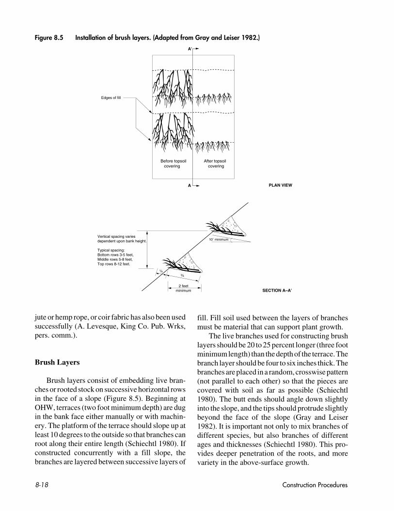
Brush Layers
Brush layers consist of embedding live bran-ches or rooted stock on successive horizontal rowsin the face of a slope (Figure 8.5). Beginning atOHW, terraces (two foot minimum depth) are dugin the bank face either manually or with machin-ery. The platform of the terrace should slope up atleast 10 degrees to the outside so that branches canroot along their entire length (Schiechtl 1980). Ifconstructed concurrently with a fill slope, thebranches are layered between successive layers of
fill. Fill soil used between the layers of branchesmust be material that can support plant growth.
The live branches used for constructing brushlayers should be 20 to 25 percent longer (three footminimum length) than the depth of the terrace. Thebranch layer should be four to six inches thick. Thebranches are placed in a random, crosswise pattern(not parallel to each other) so that the pieces arecovered with soil as far as possible (Schiechtl1980). The butt ends should angle down slightlyinto the slope, and the tips should protrude slightlybeyond the face of the slope (Gray and Leiser1982). It is important not only to mix branches ofdifferent species, but also branches of differentages and thicknesses (Schiechtl 1980). This pro-vides deeper penetration of the roots, and morevariety in the above-surface growth.
Figure 8.5 Installation of brush layers. (Adapted from Gray and Leiser 1982.)

Construction Procedures 8-19
In fill slopes, the branches should be coveredwith a minimum of 12 inches of soil. Verticalspacing between brush layers will be dictated bythe erosion potential of the bank (i.e., the soil type,rainfall, water velocities, and length and steepnessof the cut or fill slope). It may be as little as threefeet to more than nine feet (Gray and Leiser 1982).On high banks, the layers should be spaced closerat the bottom of the bank and be spaced furtherapart as one moves upslope (Gray and Leiser1982).
Schiechtl (1980) and Gray and Leiser (1982)provide further discussion of the installation ofbrush layers.
8.3.3 INTEGRATED METHODS
Joint Planting
The thickness of the existing rock layer is amajor consideration in applying this technique. Toachieve successful rooting, live stakes must bedriven through the rock voids and into the under-lying soil layer (Figure 8.6). The stakes must bealive, with side branches removed and with barkintact. The live cuttings should be sufficientlylong (up to four feet) for the base end of the staketo penetrate the soil (two feet if possible) in the
8.5 Installation of joint planting
SECTION���������������������
Rock toe key
OHW
Stream
Channel bed
Varies, dependingon gaps in riprap
Up to 48 in. long live stakes1-2 in. diameter with twolateral buds above grade.Bottom of stakes to be innative soil.
Riprap
Figure 8.6 Installation of joint planting.

����������������������������
��������
Live branches
Geotextile fabric
Fill material
Rock toe key
1-2 ft.OHW
Stream
Channel bed
Height varies
6-8 in.
10-15°
SECTION
backfill or interstices. The basal ends should becleanly cut at an angle for easy insertion into thesoil; the top should be cut flat.
Cuttings must be fresh and must be kept moist(in damp peat moss, sand, soil, or plastic bags)after they have been cut into appropriate lengths.They should be installed the same day they areharvested.
Tamp the cutting into the bank using a deadblow hammer (i.e., a hammer with the head filledwith shot or sand). In firm soil an iron bar may beneeded to make the pilot hole. The iron bar shouldbe slightly smaller than the diameter of the cuttingto ensure a snug fit. If the rod is of slightly largerdiameter, backfill the hole with sand or other finesoil around the stake. Where possible, the stakesshould be tamped in at right angles to the slope.Tamp about 0.8 of the length of the stake into theground beneath the riprap. To prevent desiccation,it is important not to have a long length of stake
exposed. If necessary, the exposed end can betrimmed to reduce moisture loss from the stake.
If construction of the rock system occurs dur-ing the dry season, it may be possible to drive livestakes between the rocks at a later date. If a portionof the backfill consists of small rock or gravel, thecuttings should be of sufficient length to reachnative soil.
Vegetated Geogrid
Vegetated geogrids are very similar to brushlayers except that the fill soil in the alternatinglayers is wrapped in a natural geotextile material(Figure 8.7). Vegetated geogrids can be installedover rock toe protection.
Geogrids in smaller projects are generallyshaped by hand. To facilitate building larger, longergeogrids, excavation equipment can be used to
Construction Procedures8-20
Figure 8.7 Installation of a vegetated geogrid shown with an optional rock toe key.

Construction Procedures 8-21
shape the geogrid; construction jigs and batterboards may also be used (Figure 8.8). The jigs,which are constructed of angle iron, hold the batterboards that shape the face of the lift to match theexisting slope contours. Shorter batter boards (threeto four feet long) and sufficient jigs will facilitatethis process. After completing the lift, the jigs areremoved with a backhoe.
Begin construction by excavating and shapingthe bank to create a bench with a 10 to 15 degreebackslope. Place at least six inches of fill materialover the bench followed by a layer of live branch-es. The live branches should be 20 to 25 percentlonger than the depth of the bench (three footminimum length). The branch layer should be fourto six inches thick. The branches are placed inrandom, crosswise pattern (not parallel to eachother) so that the individual pieces are coveredwith soil as far as possible (Schiechtl 1980). Thebutt ends should angle down slightly into theslope, and the tips should protrude slightly beyondthe face of the slope (Gray and Leiser 1982). It isimportant not only to mix branches of differentspecies, but also branches of different age andthicknesses (Schiechtl 1980). This provides deeperpenetration of the roots, and more variety in theabove surface growth. The brush is then coveredwith a layer of topsoil and lightly compacted toremove air pockets and work the soil in and aroundthe brush. Maintain a 10 to 15 degree backslope. Ifconstructed during the dry season, thoroughly weteach layer of branches and topsoil.
Next, place the jigs and batter boards for theface of the first wrapped lift. Lay pre-cut strips ofgeotextile on the bench. The geotextile strips shouldbe slightly longer than two bench widths (i.e., twobench widths plus the height of the lift). Beginningat the upstream end of the project and workingdownstream, lay the geotextile strips so that thedownstream strip overlaps the upstream strip by1.0 to 1.5 feet. The remainder of the material(slightly more than half of the fabric) should bedraped over the batter boards.
Secure the geotextile strip by staking the rearportion of the strip to the soil beneath it. Set at leasttwo rows of stakes. Commercial construction stakes12 to 24 inches in length work very well forstaking.
Backfill the lift with specified material (exca-vated native soil, or specified soil mixture). Com-pact the soil to create 1.0 to 2.0 foot lifts; maintaina 10 to 15 degree backslope with each lift. Startingat the downstream end of the project site, flip theremaining geotextile material of the most down-stream strip over the backfill. After stretching thegeotextile so that it is snug, secure it by staking. Ifpossible, stake the material into native ground. Tocomplete the lift, work in an upstream directionfollowing this sequence of steps for each strip.
Remove the batter boards and repeat the pro-cess beginning with the next layer of branches.The process continues until the structure is at final,specified height. The geogrid structure does notalways need to be built to the original bank height;the upper bank may be completed with othersystems.
There are several options for protecting andtying in the ends of the lifts. One method is to addadditional strips at the ends of each lift. This stripis laid perpendicular to the lift strips. When posi-tioning these extra strips, the upstream end strip islaid first, and then covered by subsequent lift strips(i.e., the first lift strip is contained by the end strip).Downstream, the end strip is the last strip to bepositioned (i.e., contained within the last lift strip).Beginning with the downstream end strip, fold andsecure the strips in the sequence as describedabove for constructing the lifts. Another method isuse leave extra material at the end points of thelifts. This material is folded and staked using“hospital corners” to lap and tuck the materialsnugly into place. Protecting the end points of thelifts can also be achieved by tying into existingstable features or by placing rock or large woodydebris.
Live Cribwall
The following discussion is limited to simplecribwalls less than six feet in height. A engineerknowledgeable with cribwall design should beconsulted if constructing a larger or more complexstructure.
Timbers, either round or square, 4 to 10 inchesin diameter and in varying lengths, are required for

������������������������������������������������10-15
oLive branches, criss-crossed, withtips extending beyond bank
Excavated andreshaped bank
Original bank line
Lightly tamped soil suitable forrooting, watered thoroughly
Rock toe key
OHW
10-15o
OHW
1. BANK EXCAVATION & PREPARATIONFOR FIRST GEOGRID.
2. PLACEMENT OF JIGS AND BATTER BOARDS. Batter boards—approx. 2 in. x 10 in. x 4 ft. (short lengths to follow bank curves)
Jig
Typical angle iron jig
2 in. x 6 in. angle iron upright,3 ft. high
1/2 in. x 6 in.welded iron base,3 ft. long
3. PLACEMENT OF COIR FABRIC.
OHW ����Coir fabric
1 in. x 2 in.wood stakes
a. Lay fabric pieces on bench, seams overlapping approx. 1 ft.
b. Stake in place.
c. Drape excess fabricover jig.
3-4 ft.
Eyelet
SECTIONS
6-8 in.
Construction Procedures8-22
Figure 8.8 Vegetated geogrid installation using construction jigs and batter boards.

������������������
Figure 8.8, continued
4. WRAPPING AND SECURING COIR FABRIC.
a. Fill bench with soil up to top of batter board, maintaining 10-15° slope. Water soil.
b. Pull fabric up and over to wrap soil.
c. Stake in place.
OHW
����
Coir fabric
1 in. x 2 in.wood stakes
Fill soil
5. REMOVAL OF JIGS AND BATTER BOARDS.
Slide jigs and batter boards out.
OHW
Coir fabric
6. INSTALLATION OF ADDITIONAL GEOGRID LIFTS.
a. Lay another layer of live branches andsoil on top of the geogrid and constructadditional lifts.
b. Seed and/or plant upper bank.
c. Water top soil of every layer.OHW
SECTIONS
����������
1-2 ft.
������������������������
������������������
����
1 in. x 2 in.wood stakes
Construction Procedures 8-23
Figure 8.8 Vegetated geogrid installation using construction jigs and batter boards, continued.

Construction Procedures8-24
Figure 8.9 Installation of live cribwall. (Adapted from Gray and Leiser 1982.)
������������
Header
Stretcher
Fill materialsuitable for rooting
Live branches, placed so not morethan 1/4 length extends outside of cribwall
PLAN VIEW(Fill material not shown).
FRONT ELEVATION SECTION
NOTES:
The cribwall can be constructed with either round peeled timbers or square timbers.
Fill material should be suitable for rooting, but topsoil is not necessary. Ensure even filling of soil over branches,avoiding hollow spaces.
If possible, the basal cut end of branches should extend into the soil behind the wall.
3–4¹
⁄₂ ft
.
4 ft. o.c.
Approximately 6 in. Undisturbed bankline
Rock fill
OHW
Undisturbedbankline
Rock fill
HeaderStretcher

Construction Procedures 8-25
the cribwall frame (Figure 8.9). To prevent waterquality degradation, cribwalls should constructedwith non-treated wood. The material used to back-fill the crib must include soil that will support plantgrowth.
Starting at the lowest point of the bank, exca-vate below the anticipated scour line. Constructeither a rock toe or begin placing stretchers. Placestretchers (10 to 12 feet in length) 3 to 4.5 feet apartand parallel to each other. The bank stretchershould be only a few inches from the bank. If usingrounded timbers, notching will increase the stabil-ity of the joints. Place the headers, typically fourfeet on center, on top of and perpendicular to thestretchers. Secure with rebar or spikes.
Place the initial rock fill material in the lowerportion of the cribwall (up to the OHWM). Placeand secure the next layer stretchers on top of theshort right angle timbers. The layers should bespaced approximately the same width as the thick-ness of the timber. Place fill material and compactat the OHW mark so that the soil surface slopesdown into the bank at least 10 degrees from hori-zontal. Start the first layer of live brush at theOHW mark. Arrange the branches in the openspaces between the timbers so that not more than0.25 of their length extends beyond the face of thecribwall. If possible, the basal end of the branchesshould be embedded in the native soil behind thecribwall. When placing fill material over thebranches, avoid creating large voids or hollowspaces; branches in these areas will not root.Continue with the logs or timbers, soil, and brushplacement to the top of the live cribwall.
The branch cuttings used in constructing livecribwalls are similar to those described for brushlayers. Rooted vegetation (rooted stock) may alsobe used.
Rocks may be necessary in front of the struc-ture where the water velocities at the toe areexpected to be very strong. Large boulders canalso provide cover and refuge areas for fish.
Construction of cribwalls is discussed in detailby Gray and Leiser (1982). These authors discussnumerous cribwall designs of varying size andcomplexity.
Tree Revetment
To construct a tree revetment, trees are laidalong the bank with the basal ends oriented up-stream (Figure 8.10). They should be overlapped0.25 to 0.33 of their length to insure continuousprotection to the bank. The number of trees useddepends on the length of bank to protect.
The trunks are cabled to deadman anchors inthe bank, with the top of one tree overlapping andcabled to the trunk of the next tree downstream ina shingle-like effect. Piles can be used in lieu ofdeadman anchors, provided they can be drivenwell below the point of maximum bed scour. Toassure proper cable tension, pull and hold the treesin against the bank while the cables are beingattached. Use cable clamps to attach the cable tothe trees. Cable the tip of the last tree in snuglyagainst the bank to prevent bank scour at thislocation.
Do not trim branches of the trees. The use ofgreen trees will result in less limb loss duringinstallation. Fill large gaps between the trees andthe bank with additional trees and/or rock as needed.Rocks and trees together often form a more effec-tive structure than either alone. It is important thatthis type of revetment be adequately anchored toprevent trees from breaking free and damagingdownstream structures.
8.3.4 HABITAT COMPONENTS
Large Woody Debris
Whole trunks with roots and single logs can befirmly buried into the riverbank or bed, wedged inplace with other woody elements and/or rockmaterials, or cabled to buried “deadman,” tie-backanchors or other structures, or even living trees.Cables can also be fixed to the logs and glued withepoxies into holes drilled into large rocks. Otheremplacements rely on pounding long lengths ofsteel reinforcing bar into underlying sedimentsthrough holes drilled through the wood pieces.
Root wads or stumps may be firmly wedged,cabled or nailed in place with rebar. Cabling can be

Figure 7.6 Installation of anchored tree
Deadman
Anchor cable
Flow
PLAN VIEW
length varies
SECTION
Deadman
Anchorcable
OHW
Construction Procedures8-26
accomplished by drilling through the root and/orstump portion, passing a cable through the hole,and cementing each end of the cable to a largerock. A variation is to swage (i.e., crimp) a ferrule(i.e., bushing) around the cable; the free end ispassed through a hole drilled through the center ofthe root and up through the center of the tree rings.The cable is then epoxied into a large boulder. If
cabled, precautions should be taken to minimizepossible movement or shifting of these devices.Project designers should also be aware that eachpiece of wire rope introduced into the river systemis a potential hazard to swimmers, boaters, rafters,and wildlife.
In large river systems such as the Green orCedar Rivers, secure large woody debris (prefer-
Figure 8.10 Installation of a tree revetment.

Construction Procedures 8-27
ably 20 feet long or more and 20 inch minimumdiameter) by burying them directly into the rocktoe buttress (Figure 8.11) (A. Levesque, KingCounty SWMD, pers. comm., 1992). Where facil-ity reconstruction will allow, this can occur with-out further excavation into the bankline. In othercases, especially where setback modifications tothe facility alignment are proposed, a trench maybe required to embed the top of the log partially
into the bankline itself. In both cases, the logsshould be secured firmly in place with large rock(three to five foot minimum diameter rock), witha minimum of four to five rocks placed along itslength. Smaller stone and granular materials maybe needed to fully embed the log in fine-grainedbed or bank excavation materials. The root end ofthe log should protrude from five to eight feetbeyond the edge of the rock installation, at a 30 to
Figure 8.11 Integrated system using large woody debris.
Top of bank
Staked fascine
Live cuttings
2 ft. minimum layer heavy–loose riprap
3-5 ft. minimumdiameter rock
2 ft. diameter, 20-30 ft. long log with roots.Trench and imbed log bole 12-16 ft. minimum distance into riverbed below existing OHWM.Secure with rock toe.
1 ft. minimum layer of light-loose riprap
1–11⁄2 ft. layer of 1⁄4–3 in. rounded gravel
Coir geogrid
Figure 8.11 Integrated system using large woody debris.
ALIGNMENT OF LARGE WOOD IN THIS CONFIGURATION NO LONGER USED DUE TO SAFETY CONCERNS FOR RECREATIONAL RIVER USERS. (APRIL 2009).

45 degree angle to the bankline and at 2 to 20degrees downward towards the streambed. Theentire log should be placed below OHW to keep itfully saturated at lower flows. It is recommendedthat layers of woody vegetative cuttings and top-soil be placed directly over the full dimension ofthe log and rock emplacement. The vegetationshould be deeply rooting and tolerant of saturatedsoils.
Fishrocks
The proper rock position in the flow dependsupon its shape, the angle at which the flow hits therock, and the site objectives. Place rocks such that,at bankfull discharge, the flow is deflected towardthe area where the scour is desired. Orsborn andBumstead (1986) recommend placing the longaxis of the rock parallel to the flow. This orienta-tion reduces the chance of the boulder tipping intoits scour hole and is less likely to direct the flowinto the bank. To ensure the stability of rocks,align them with the flow so that the flow will notrotate them.
Avoid placing rocks so that flow is directedinto erodible banks (Wesche 1985). Before install-ing, examine the stability of a fishrock from threeperspectives. First, the shape and orientation of therock will have an impact upon the depth andvolume of scour. Second, expect upstream rota-tion of the fishrock as most undercutting will occuron the upstream face of the rock. Under highvelocities, the fishrock may become cantileveredand tip into the scour hole it has created. Finally,expect an elongated rock to naturally shift itsmajor axis at least 45 degrees to the flow. Plan forthis and initially install elongated rocks approxi-mately parallel to the flow since this orientation ismore naturally stable.
Whenever possible, use equipment stationedon the bank to place rock. In larger rivers, instal-lation of fish rocks may require operation of equip-ment instream.
Construction Procedures8-28
8.4 CONSTRUCTION INSPECTIONAND SITE CLEANUP
Site inspection and construction monitoringmust occur during project installation to ensurethat the design specifications are met. While fa-cilities can be adequately designed, projects willnot be successful if construction materials do notmeet the required specifications or if the materialswere installed improperly. Many of the itemslisted in Section 8.1 are activities that occur through-out construction of the project. At the close ofconstruction, the project supervisor should ensurethat all elements of the design have been installedaccording to specifications. Any changes to thedesign specifications should be documented asrevisions to the final design drawings to reflect theas-built condition of the project.
At the end of each work day, constructionsites, especially in residential areas, should haveconstruction debris, plant materials, soil, tools,and other material picked up from roads and otherareas. The site should be left as neat as possible andpractical every day. During the day, vehicles andequipment not in use should be stored out of theway of local residents or businesses. These mea-sures help maintain friendly relations with peopleinconvenienced by the presence of equipment andwork crews.
Advance planning and organization of thework site also eliminates rearrangement of stock-piled materials. Items should be kept readily avail-able, but not in the way of workers or equipment.The area immediately adjacent to the streambankusually must be kept clear to allow equipmentaccess where it is needed. When several stabiliza-tion components will be used, areas should beidentified for these specific materials so that thequantities available can be determined quicklyand clean-up is organized. It is preferable not tostore cut plant material overnight; if it must be,provide an area where the stems can be coveredwith moist (not wet) soil or stored with the basalends in the stream.
At the completion of a project, staging areasshould be restored to preconstruction conditions.Remove unneeded or scrap material that couldendanger wildlife or enter the stream, and repair

Construction Procedures 8-29
damage to property, landscaping, lawns, and drive-ways caused by the work. Grade and reseed dis-turbed lawns or areas that may be subject tosurface erosion.
If possible, return plant containers to the nurs-ery or to a recycling or redistribution center. Manynurseries give cash or credit towards future pur-chases for returned plant containers. Clean Wash-ington Center (206-464-7040) and the IndustrialMaterials Exchange (IMEX) (206-296-4899) aretwo organizations involved in waste reduction andwho can provide information on how to acquire ordispose of many recyclable and reusable products.This includes landscaping materials such as com-mercial compost and plant pots.

Construction Procedures8-30
RECOMMENDED SOURCES FORADDITIONAL INFORMATION
Coppin, N.J. and I.G. Richards. 1990. Use ofVegetation in Civil Engineering. London,England.
Gray, D.H. and A.T. Leiser. 1982. BiotechnicalSlope Protection and Erosion Control.Van Nostrand Reinhold Company. NewYork, N.Y.
Schiechtl, H. 1980. Bioengineering for LandReclamation and Conservation. Universityof Alberta Press. Edmonton.