chapter 8site.iugaza.edu.ps/mhaiba/files/2012/01/ch8-vapor-power-systems.pdf · chapter 8 vapor...
TRANSCRIPT

Chapter 8
Vapor Power
Systems
5/7/2012 8:47 AM
Dr. Mohammad Abuhaiba, PE 1

chapter objective
Study vapor power plants in which the
working fluid is alternately vaporized
and condensed.
5/7/2012 8:47 AM
Dr. Mohammad Abuhaiba, PE
2
Modeling Vapor Power Systems
To facilitate thermodynamic analysis, overall
plant can be broken down into four major
subsystems identified by letters A through D on
the diagram.
The focus in this chapter is subsystem A, where
important energy conversion from heat to work
occurs.
5/7/2012 8:47 AM
Dr. Mohammad Abuhaiba, PE
3

5/7/2012 8:47 AM
Dr. Mohammad Abuhaiba, PE
4
Modeling Vapor Power Systems

Modeling Vapor Power Systems Subsystem B supplies energy required to vaporize water
passing through boiler. In fossil-fuel plants, this is accomplished by heat transfer to working fluid passing through tubes and drums in boiler from hot gases produced by combustion of a fossil fuel.
Regardless of energy source, vapor produced in boiler passes through a turbine, where it expands to a lower pressure.
The shaft of turbine is connected to an electric generator (subsystem D).
Vapor leaving turbine passes through condenser, where it condenses on outside of tubes carrying cooling water.
Cooling water circuit comprises subsystem C. Cooling water is sent to a cooling tower, where energy taken up in condenser is rejected to atmosphere. Cooling water is then recirculated through the condenser.
5/7/2012 8:47 AM
Dr. Mohammad Abuhaiba, PE
5

Analyzing Vapor Power
Systems - Rankine Cycle Evaluating Principal Work and Heat Transfers
Rankine cycle is a
thermodynamic cycle that
models subsystem A on Fig.
8.1
5/7/2012 8:47 AM
Dr. Mohammad Abuhaiba, PE
6

Analyzing Vapor Power
Systems - Rankine Cycle Evaluating Principal Work and Heat Transfers
TURBINE
CONDENSER
5/7/2012 8:47 AM
Dr. Mohammad Abuhaiba, PE
7

Analyzing Vapor Power
Systems - Rankine Cycle Evaluating Principal Work and Heat Transfers
Pump
Boiler
Thermal Efficiency
5/7/2012 8:47 AM
Dr. Mohammad Abuhaiba, PE
8

Analyzing Vapor Power
Systems - Rankine Cycle Evaluating Principal Work and Heat Transfers
back work ratio: bwr, ratio of pump work input to work
developed by the turbine
5/7/2012 8:47 AM
Dr. Mohammad Abuhaiba, PE
9

Analyzing Vapor Power
Systems - Rankine Cycle Ideal Rankine Cycle
5/7/2012 8:47 AM
Dr. Mohammad Abuhaiba, PE
10

EXAMPLE 8.1
Ideal Rankine Cycle
Steam is the working fluid in an ideal Rankine cycle. Saturated
vapor enters the turbine at 8.0 MPa and saturated liquid exits the
condenser at a pressure of 0.008 MPa. The net power output of the
cycle is 100 MW. Determine for the cycle
a. The thermal efficiency
b. back work ratio
c. mass flow rate of the steam, in kg/h
d. rate of heat transfer into the working fluid as it passes
through the boiler, in MW
e. rate of heat transfer, from the condensing steam as it passes
through the condenser, in MW
f. mass flow rate of the condenser cooling water, in kg/ h, if cooling
water enters the condenser at 15°C and exits at 35°C.
5/7/2012 8:47 AM
Dr. Mohammad Abuhaiba, PE
11

EXAMPLE 8.1
Ideal Rankine Cycle
5/7/2012 8:47 AM
Dr. Mohammad Abuhaiba, PE
12

Analyzing Vapor Power
Systems - Rankine Cycle Effects of Boiler and Condenser Pressures
Thermal efficiency of power cycles tends to increase as average temperature at which energy is added by heat transfer increases and/or average temperature at which energy is rejected decreases.
Increasing boiler pressure of ideal Rankine cycle tends to increase thermal efficiency.
5/7/2012 8:47 AM
Dr. Mohammad Abuhaiba, PE
13

Analyzing Vapor Power
Systems - Rankine Cycle Effects of Boiler and Condenser Pressures
Decreasing condenser pressure tends to increase
thermal efficiency.
5/7/2012 8:47 AM
Dr. Mohammad Abuhaiba, PE
14

Analyzing Vapor Power
Systems - Rankine Cycle Effects of Boiler and Condenser Pressures
Lowest feasible condenser pressure is saturation pressure corresponding to ambient temperature, lowest possible temperature for heat rejection to surroundings.
The goal of maintaining lowest practical turbine exhaust (condenser) pressure is a primary reason for including the condenser in a power plant. Liquid water at atmospheric pressure could be drawn into boiler by a pump, and steam could be discharged directly to atmosphere at turbine exit.
By including a condenser in which steam side is operated at a pressure below atmospheric, turbine has a lower-pressure region in which to discharge, resulting in a significant increase in net work and thermal efficiency.
The addition of a condenser also allows working fluid to flow in a closed loop.
5/7/2012 8:47 AM
Dr. Mohammad Abuhaiba, PE
15

Analyzing Vapor Power
Systems - Rankine Cycle Comparison with Carnot Cycle
Carnot cycle has two shortcomings as a model for simple vapor power
cycle:
1. Heat passing to working fluid of a vapor power plant is usually
obtained from hot products of combustion cooling at approximately
constant pressure. To exploit fully the energy released on
combustion, hot products should be cooled as much as possible.
First portion of heating process of Rankine cycle is achieved by
cooling combustion products below max TH. With Carnot cycle,
combustion products would be cooled at the most to TH. Thus, a
smaller portion of energy released on combustion would be used.
2. State 3 is a two-phase liquid–vapor mixture. Significant practical
problems are encountered in developing pumps that handle two-
phase mixtures, as would be required by Carnot cycle. It is far easier
to condense vapor completely and handle only liquid in pump, as is
done in Rankine cycle. Pumping from 3 to 4 and constant-pressure
heating without work from 4 to 4’ are processes that can be closely
achieved in practice.
5/7/2012 8:47 AM
Dr. Mohammad Abuhaiba, PE
16
Ideal Rankine cycle has a lower thermal efficiency than Carnot cycle having
same max TH and min TC because average temperature between 4 and 4’ is
less than TH.

Analyzing Vapor Power
Systems - Rankine Cycle Principal Irreversibilities and Losses - TURBINE
An actual adiabatic
expansion through turbine
is accompanied by an
increase in entropy.
Work developed is less
than for corresponding
isentropic expansion.
Isentropic turbine
efficiency is
5/7/2012 8:47 AM
Dr. Mohammad Abuhaiba, PE
17

Analyzing Vapor Power
Systems - Rankine Cycle Principal Irreversibilities and Losses - PUMP
Work input to pump required to overcome frictional effects reduces net power output of plant.
In absence of heat transfer to surroundings, there would be an increase in entropy across the pump.
Work input for this process is greater than for corresponding isentropic process.
Isentropic pump efficiency is
5/7/2012 8:47 AM
Dr. Mohammad Abuhaiba, PE
18

EXAMPLE 8.2 Rankine Cycle with Irreversibilities
Reconsider the vapor power cycle of Example 8.1, but include in the analysis that the turbine and the pump each have an isentropic efficiency of 85%. Determine for the modified cycle
a. thermal efficiency
b. mass flow rate of steam, in kg/h for a net power output of 100 MW
c. rate of heat transfer into the working fluid as it passes through the boiler, in MW
d. rate of heat transfer from the condensing steam as it passes through the condenser, in MW
e. mass flow rate of the condenser cooling water, in kg/h, if cooling water enters the condenser at 15°C and exits as 35°C. Discuss the effects on the vapor cycle of irreversibilities within the turbine and pump.
5/7/2012 8:47 AM
Dr. Mohammad Abuhaiba, PE
19

EXAMPLE 8.2 Rankine Cycle with Irreversibilities
5/7/2012 8:47 AM
Dr. Mohammad Abuhaiba, PE
20
Improving Performance - Superheat and Reheat
An increase in boiler pressure or a decrease in condenser pressure may result in a reduction of steam quality at exit of turbine.
If quality of mixture passing through turbine becomes too low, impact of liquid droplets in flowing liquid–vapor mixture can erode turbine blades, causing a decrease in turbine efficiency and an increased need for maintenance.
Common practice: maintain at least 90% quality at turbine exit.
Cycle modifications known as superheat and reheat permit advantageous operating pressures in boiler and condenser and yet offset problem of low quality of turbine exhaust.
5/7/2012 8:47 AM
Dr. Mohammad Abuhaiba, PE
21

Improving Performance - Superheat
Further energy can be added by heat
transfer to steam, bringing it to a
superheated vapor condition at
turbine inlet.
Steam generator: combination of
boiler and superheater.
The cycle with superheat has a higher
average temperature of heat addition
than cycle without superheating, so
thermal efficiency is higher.
Quality at turbine exhaust is greater.
Superheating tends to alleviate
problem of low steam quality at
turbine exhaust.
With sufficient superheating, turbine
exhaust state may even fall in the
superheated vapor region.
5/7/2012 8:47 AM
Dr. Mohammad Abuhaiba, PE
22

Improving Performance - Reheat
Steam does not expand to condenser pressure in a
single stage. The steam expands through a first-stage
turbine (Process 1–2) to some pressure between
steam generator and condenser pressures.
Steam is then reheated in steam generator (Process
2–3).
After reheating, steam expands in a second-stage
turbine to condenser pressure (Process 3–4).
Principal advantage of reheat: increase quality of
steam at turbine exhaust.
5/7/2012 8:47 AM
Dr. Mohammad Abuhaiba, PE
23

Improving Performance - Reheat
5/7/2012 8:47 AM
Dr. Mohammad Abuhaiba, PE
24

Improving Performance - Supercritical Cycle
Temperature of steam entering turbine is
restricted by metallurgical limitations imposed
by materials used to fabricate superheater,
reheater, and turbine.
High pressure in steam generator requires
piping that can withstand great stresses at
elevated temperatures.
Although these factors limit gains that can be
realized through superheating and reheating,
improved materials and methods of fabrication
have permitted significant increases over years
in max allowed cycle temperatures and steam
generator pressures, with corresponding
increases in thermal efficiency.
5/7/2012 8:47 AM
Dr. Mohammad Abuhaiba, PE
25

EXAMPLE 8.3 Ideal Reheat Cycle
Steam is the working fluid in an ideal Rankine cycle with superheat and reheat. Steam enters the first-stage turbine at 8.0 MPa, 480°C, and expands to 0.7 MPa. It is then reheated to 440°C before entering the second-stage turbine, where it expands to the condenser pressure of 0.008 MPa. The net power output is 100 MW. Determine
a. thermal efficiency of the cycle
b. mass flow rate of steam, in kg/h
c. rate of heat transfer from the condensing steam as it passes through the condenser, in MW. Discuss the effects of reheat on the vapor power cycle.
5/7/2012 8:47 AM
Dr. Mohammad Abuhaiba, PE
26

EXAMPLE 8.3 Ideal Reheat Cycle
5/7/2012 8:47 AM
Dr. Mohammad Abuhaiba, PE
27

EXAMPLE 8.4 Reheat Cycle with Turbine Irreversibility
Reconsider the reheat cycle of Example 8.3, but include in the analysis that each turbine stage has the same isentropic efficiency.
a. If ht = 85%, determine the thermal efficiency.
b. Plot the thermal efficiency versus turbine stage efficiency ranging from 85 to 100%.
5/7/2012 8:47 AM
Dr. Mohammad Abuhaiba, PE
28

Open Feed Water Heaters Open feedwater heater, a direct contact-type heat exchanger in which streams at
different temperatures mix to form a stream at an intermediate temperature.
For this cycle, working fluid passes isentropically through turbine stages and pumps,
and the flow through steam generator, condenser, and feed water heater takes
place with no pressure drop in any of these components.
Steam enters first-stage turbine at state 1 and expands to state 2, where a fraction
of total flow is extracted, or bled, into an open feedwater heater operating at
extraction pressure, p2. The rest of steam expands through second-stage turbine to
state 3. This portion of total flow is condensed to saturated liquid, state 4, and then
pumped to extraction pressure and introduced into feedwater heater at state 5.
A single mixed stream exits feed water heater at state 6.
Mass flow rates of streams entering feed water heater are chosen so that stream
exiting feed water heater is a saturated liquid at the extraction pressure.
Liquid at state 6 is then pumped to steam generator pressure and enters steam
generator at state 7. Finally, working fluid is heated from state 7 to state 1 in steam
generator.
5/7/2012 8:47 AM
Dr. Mohammad Abuhaiba, PE
29

Open Feed Water Heaters
5/7/2012 8:47 AM
Dr. Mohammad Abuhaiba, PE
30

Open Feed Water Heaters Heat addition would take place from state 7 to state 1,
rather than from state a to state 1, as would be the case without regeneration.
Accordingly, amount of energy that must be supplied from combustion of a fossil fuel, to vaporize and superheat the steam would be reduced.
Only a portion of total flow expands through 2nd stage turbine (Process 2–3), however, so less work would be developed as well.
In practice, operating conditions are chosen so that reduction in heat added more than offsets the decrease in net work developed, resulting in an increased thermal efficiency in regenerative power plants.
5/7/2012 8:47 AM
Dr. Mohammad Abuhaiba, PE
31
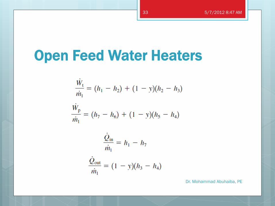
Open Feed Water Heaters
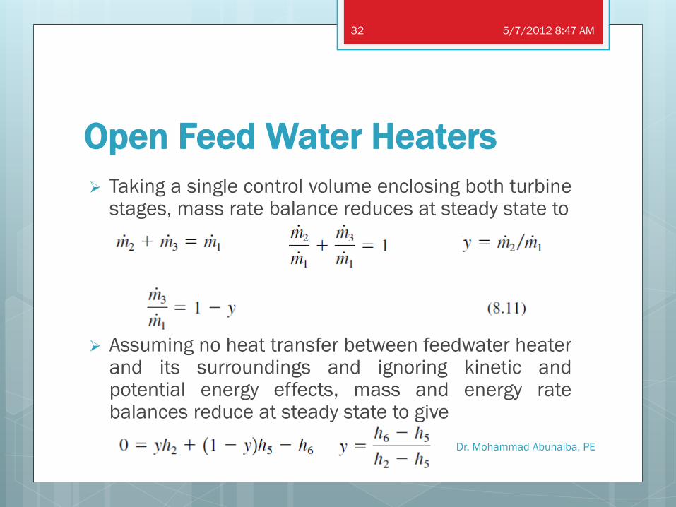
Taking a single control volume enclosing both turbine stages, mass rate balance reduces at steady state to
Assuming no heat transfer between feedwater heater and its surroundings and ignoring kinetic and potential energy effects, mass and energy rate balances reduce at steady state to give
5/7/2012 8:47 AM
Dr. Mohammad Abuhaiba, PE
32
Open Feed Water Heaters
5/7/2012 8:47 AM
Dr. Mohammad Abuhaiba, PE
33

EXAMPLE 8.5 Regenerative Cycle with Open Feedwater Heater
Consider a regenerative vapor power cycle with one open feedwater heater. Steam enters the turbine at 8.0 MPa, 480°C and expands to 0.7 MPa, where some of the steam is extracted and diverted to the open feedwater heater operating at 0.7 MPa. The remaining steam expands through the second-stage turbine to the condenser pressure of 0.008 MPa. Saturated liquid exits the open feedwater heater at 0.7 MPa. The isentropic efficiency of each turbine stage is 85% and each pump operates isentropically. If the net power output of the cycle is 100 MW, determine
a. thermal efficiency
b. mass flow rate of steam entering first turbine stage, in kg/h.
5/7/2012 8:47 AM
Dr. Mohammad Abuhaiba, PE
34

EXAMPLE 8.5 Regenerative Cycle with Open Feedwater Heater
5/7/2012 8:47 AM
Dr. Mohammad Abuhaiba, PE
35

Improving Performance Closed Feedwater Heaters
Closed heaters: shell-and-tube-type recuperators in which feedwater
temperature increases as extracted steam condenses on outside of tubes
carrying feedwater.
Since the two streams do not mix, they can be at different pressures.
5/7/2012 8:47 AM
Dr. Mohammad Abuhaiba, PE
36

Improving Performance Closed Feedwater Heaters
5/7/2012 8:47 AM
Dr. Mohammad Abuhaiba, PE
37

Improving Performance Multiple Feedwater Heaters
5/7/2012 8:47 AM
Dr. Mohammad Abuhaiba, PE
38

EXAMPLE 8.6 Reheat–Regenerative Cycle with Two
Feedwater Heaters
Consider a reheat–regenerative vapor power cycle with two feedwater heaters, a
closed feedwater heater and an open feedwater heater. Steam enters the first
turbine at 8.0 MPa, 480°C and expands to 0.7 MPa. The steam is reheated to
440°C before entering the second turbine, where it expands to the condenser
pressure of 0.008 MPa. Steam is extracted from the first turbine at 2 MPa and
fed to the closed feedwater heater. Feedwater leaves the closed heater at
205°C and 8.0 MPa, and condensate exits as saturated liquid at 2 MPa. The
condensate is trapped into the open feedwater heater. Steam extracted from
the second turbine at 0.3 MPa is also fed into the open feedwater heater, which
operates at 0.3 MPa. The stream exiting the open feedwater heater is saturated
liquid at 0.3 MPa. The net power output of the cycle is 100 MW. There is no
stray heat transfer from any component to its surroundings. If the working fluid
experiences no irreversibilities as it passes through the turbines, pumps, steam
generator, reheater, and condenser, determine
a. thermal efficiency
b. mass flow rate of the steam entering the first turbine, in kg/h
5/7/2012 8:47 AM
Dr. Mohammad Abuhaiba, PE
39

EXAMPLE 8.6 Reheat–Regenerative
Cycle with Two
Feedwater Heaters
5/7/2012 8:47 AM
Dr. Mohammad Abuhaiba, PE
40

Home Work Assignment CH8
1, 9, 16, 22, 33, 41, 47
Due Wednesday
16/5/2012
5/7/2012 8:47 AM
Dr. Mohammad Abuhaiba, PE
41