chapter 9: input/output the architecture of computer hardware and systems software: an information...
Post on 19-Dec-2015
239 views
TRANSCRIPT
Chapter 9: Input/Output
The Architecture of Computer Hardware and Systems Software:
An Information Technology Approach
3rd Edition, Irv Englander
John Wiley and Sons 2003
Wilson Wong, Bentley College
Linda Senne, Bentley College

Chapter 9 Input / Output 9-2
Basic Model
Processing speed or program execution determined primarily by ability of I/O
operations to stay ahead of processor.
Input Process Output

Chapter 9 Input / Output 9-3
I/O ConsiderationsSpeed Issues CPU operates at speeds much faster than the fastest I/O
device Devices operate at different speeds Bursts of data Block data transfer required for some devices
Coordination Several devices perform I/O simultaneously Unexpected input Various input formats Status information needed for each device
Chapter 9 Input / Output 9-4
I/O Device Interface Issues Different formats
parallel interface serial interface
Buffering of data Burst vs. stream Different control requirements
electromechanical

Chapter 9 Input / Output 9-5
Examples of I/O Devices

Chapter 9 Input / Output 9-6
Simple I/O Configuration

Chapter 9 Input / Output 9-7
I/O Modules Functions Recognizes messages from device(s) addressed to it
and accepts commands from the CPU Provides a buffer where the data from memory can be
held until it can be transferred to the disk Provides the necessary registers and controls to
perform a direct memory transfer Physically controls the device Copies data from its buffer to the device/from the
CPU to its buffer Notifies with interrupts
Chapter 9 Input / Output 9-8
Input/Output Modules
Programmed I/O CPU controlled I/O
Interrupt Driven I/O External input controls
Direct Memory Access Controllers Method for transferring data between main
memory and a device that bypasses the CPU
Chapter 9 Input / Output 9-9
Programmed I/O I/O data and address registers in CPU One word transfers Address information for each I/O device
LMC I/O capability for 100 devices
Full instruction fetch/execute cycle Primary use:
keyboards communication with I/O modules (see DMA)
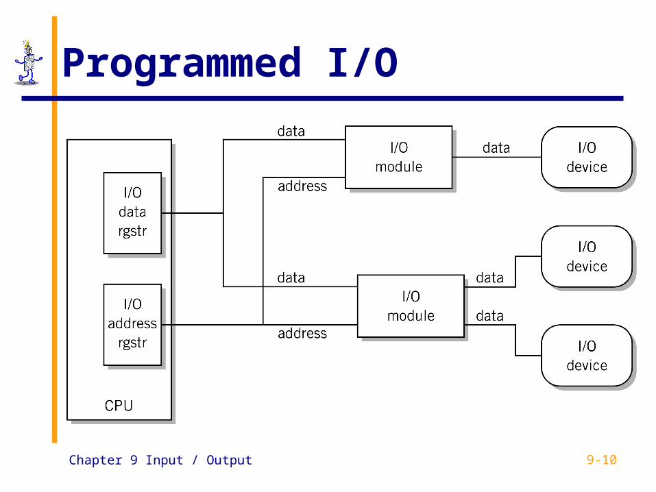
Chapter 9 Input / Output 9-10
Programmed I/O

Chapter 9 Input / Output 9-11
Programmed I/O Example

Chapter 9 Input / Output 9-12
Programmed I/O Example

Chapter 9 Input / Output 9-13
Interrupts Signal that causes the CPU to alter its
normal flow on instruction execution frees CPU from waiting for events provides control for external input
Examples unexpected input abnormal situation illegal instructions multitasking, multiprocessing

Chapter 9 Input / Output 9-14
The CPU - The Interrupt Cycle Fetch / Execute cycle Interrupt cycle
HALT
START
Fetch Next Instruction
Execute Instruction
Check/ProcessInterrupt
Interrupts Disabled

Chapter 9 Input / Output 9-15
Interrupt Terminology Interrupt lines (hardware) Interrupt request Interrupt handlers
Program that services the interrupt Also known as an interrupt routine
Process Control Block (PCB) Located in a part of memory known as the stack
area All registers of a program are saved here before
control is transferred to the interrupt handler

Chapter 9 Input / Output 9-16
Interrupt Terminology
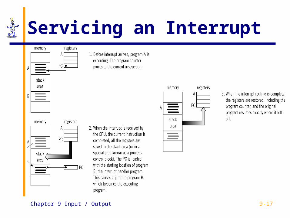
Servicing the interrupt suspends program in progress saves pertinent information including last
instruction executed and data values in registers in the PCB (process control block)
branches to interrupt handler
Chapter 9 Input / Output 9-17
Servicing an Interrupt

Chapter 9 Input / Output 9-18
Use of Interrupts
Notify that an external event has occurred real-time or time-sensitive
Signal completion printer ready or buffer full
Allocate CPU time time sharing
Indicate abnormal event (CPU originates for notification and recovery) illegal operation, hardware error
Software interrupts
Chapter 9 Input / Output 9-19
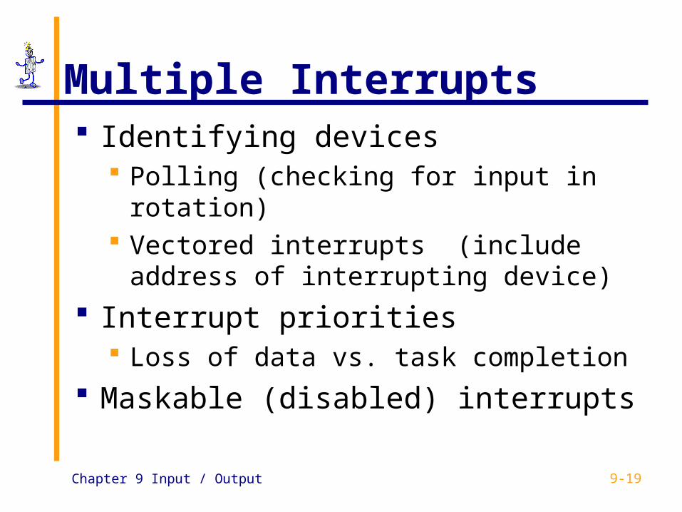
Multiple Interrupts Identifying devices
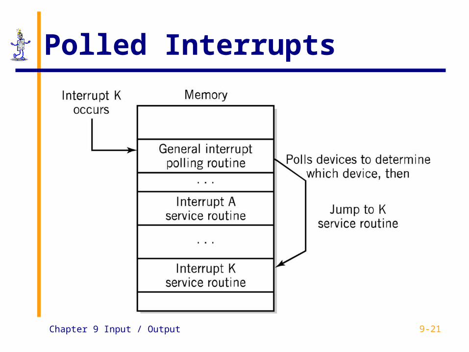
Polling (checking for input in rotation) Vectored interrupts (include address of
interrupting device)
Interrupt priorities Loss of data vs. task completion
Maskable (disabled) interrupts

Chapter 9 Input / Output 9-20
Vectored Interrupts
Chapter 9 Input / Output 9-21
Polled Interrupts

Chapter 9 Input / Output 9-22
Multiple Interrupts Example

Chapter 9 Input / Output 9-23
Direct Memory Access Transferring large blocks of data Direct transfer to and from memory CPU not actively involved in transfer itself Required conditions for DMA
The I/O interface and memory must be connected The I/O module must be capable of reading and
writing to memory Conflicts between the CPU and the I/O module
must be avoided

Chapter 9 Input / Output 9-24
DMA Instruction Set Application program requests I/O service
from operating system privileged instructions
To initiate DMA, programmed I/O is used to send the following information:
1. location of data on I/O device2. the starting location in memory3. the size of the block4. read/write
Interrupt to CPU upon completion

Chapter 9 Input / Output 9-25
DMA Initiation and Control
Chapter 9 Input / Output 9-26
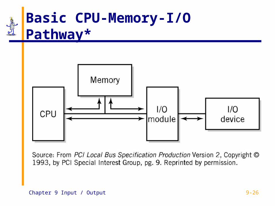
Basic CPU-Memory-I/O Pathway*

Chapter 9 Input / Output 9-27
Bus Configuration
Chapter 9 Input / Output 9-28
Bus Characteristics
Data width in bits carried simultaneously Throughput, i.e., data transfer rate in
bits per second Point-to-Point vs. Multipoint Parallel vs. Serial Use Distance Protocol

Chapter 9 Input / Output 9-29
Bus Hierarchy Processor bus: on-chip Cache bus (backside bus) Memory bus (front-side bus)
connects the memory subsystem and processor Local I/O bus
high-speed bus used to connect performance critical peripherals to memory and processor
Examples: PCI, VESA Local Bus Standard I/O bus
connects slower peripherals (ISA) to Local I/O bus

Chapter 9 Input / Output 9-30
Wintel Bus Systems ISA: Industry Standard Architecture MCA: Micro Channel Architecture EISA: Extended Industry Standard Architecture Local Bus
PCI: Peripheral Component Interconnect (also Apple, Sun, Compaq Alpha Server)
VLB: VESA (Video Electronics Standards Association) Local Bus
AGP: Accelerated Graphics Port Point-to-point channel from graphics controller to main
memory Co-exists with PCI
Chapter 9 Input / Output 9-31
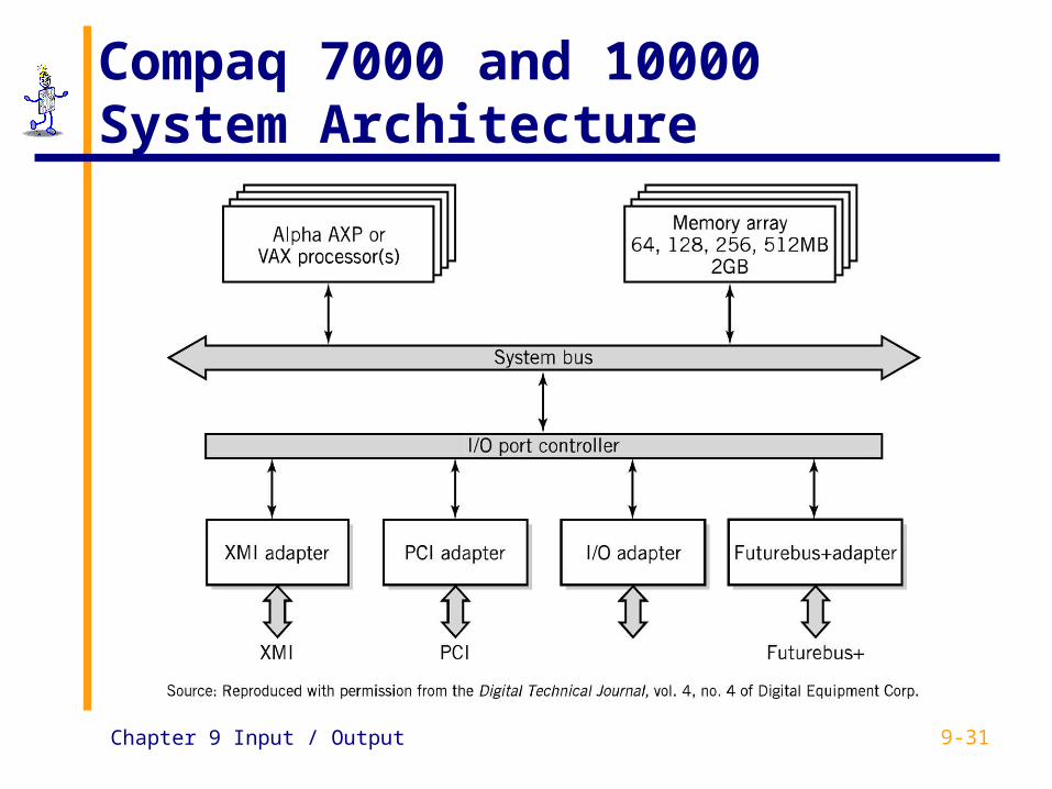
Compaq 7000 and 10000 System Architecture

Chapter 9 Input / Output 9-32
External Interface Buses and Ports
Parallel port Serial port
RS-232C and RS-422 buses SCSI
Small Computer System Interface USB, USB-2
Universal Serial Bus IEEE 1394
Firewire i.link

Chapter 9 Input / Output 9-33
SCSI Bus
ANSI standard but multiple variations Really an I/O bus rather than simple interface
Supports multiple devices from a single SCSI port

Chapter 9 Input / Output 9-34
Root
Hub
Hub Hub
USB
Multipoint bus Hubs provide
multiple connection points for I/O devices
Supports 127 devices
Hub
Topology Example
Chapter 9 Input / Output 9-35
USB and FireWire (IEEE 1394)
Both serial, multipoint bus specifications Add/remove devices w/o powering
down Packet protocol for isochronous data
transfer Isochronous: delivery at regular time
intervals Guarantee specified throughput
Chapter 9 Input / Output 9-36
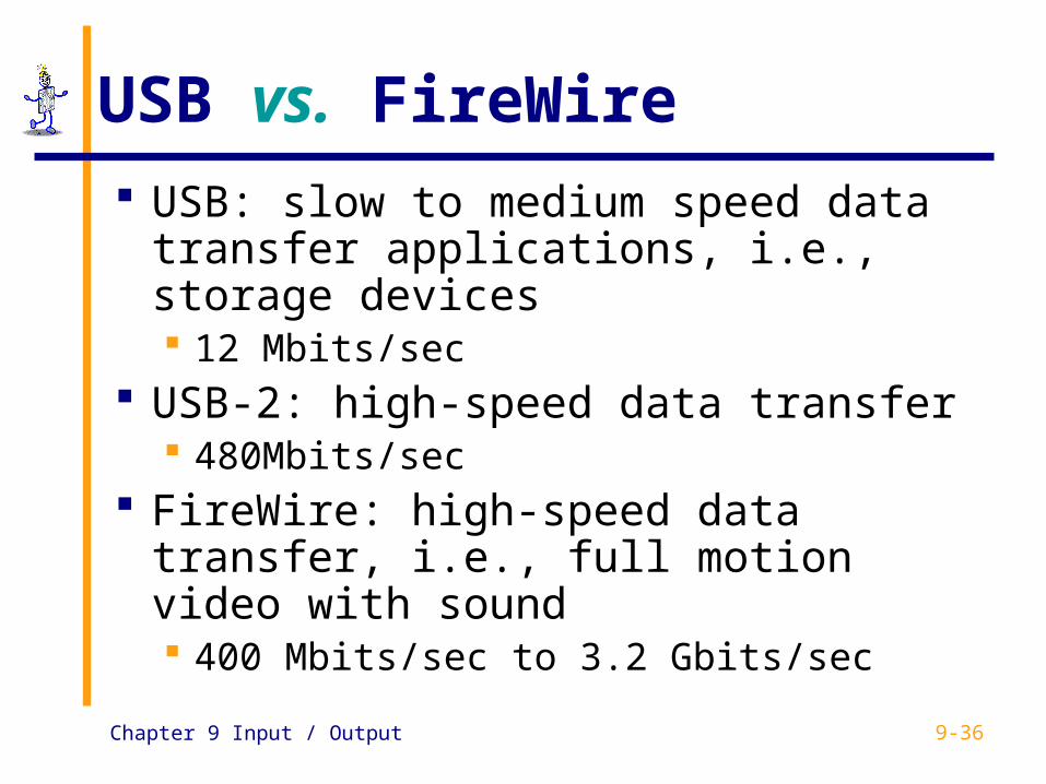
USB vs. FireWire
USB: slow to medium speed data transfer applications, i.e., storage devices 12 Mbits/sec
USB-2: high-speed data transfer 480Mbits/sec
FireWire: high-speed data transfer, i.e., full motion video with sound 400 Mbits/sec to 3.2 Gbits/sec
Chapter 9 Input / Output 9-37
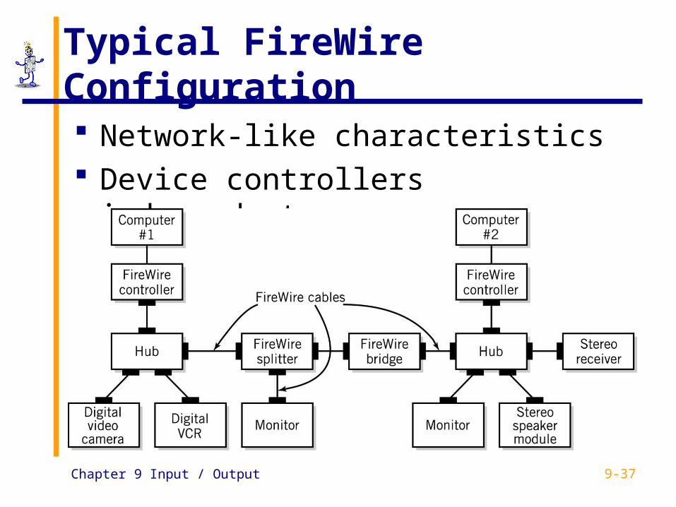
Typical FireWire Configuration
Network-like characteristics Device controllers independent
Chapter 9 Input / Output 9-38
Channel Architecture Used in IBM mainframe computers Channel subsystem
Separate I/O processor that serves as a CPU for I/O operations
Channel control words Programs that transfer data between memory and
an I/O device using DMA Subchannels
Connected to a control unit module through one or more channel paths
Similar role to a device controller

Chapter 9 Input / Output 9-39
I/O Channel Architecture
Chapter 9 Input / Output 9-40
Copyright 2003 John Wiley & Sons
All rights reserved. Reproduction or translation of this work beyond that permitted in Section 117 of the 1976 United States Copyright Act without express permission of the copyright owner is unlawful. Request for further information should be addressed to the permissions Department, John Wiley & Songs, Inc. The purchaser may make back-up copies for his/her own use only and not for distribution or resale. The Publisher assumes no responsibility for errors, omissions, or damages caused by the use of these programs or from the use of the information contained herein.”