chato low gravity cryogenic liquid acquisition for space exploration 2014
TRANSCRIPT

1
National Aeronautics and Space AdministrationNational Aeronautics and Space Administration
Low Gravity Cryogenic Liquid Acquisition for Space Exploration
David J. Chato1, Jason W. Hartwig1, Enrique Rame2, John B. McQuillen1
1NASA Glenn Research Center, Cleveland, OH, USA2National Center for Space Exploration Research, Cleveland, OH, USA
Low Gravity Cryogenic Liquid Acquisition for Space Exploration
David J. Chato1, Jason W. Hartwig1, Enrique Rame2, John B. McQuillen1
1NASA Glenn Research Center, Cleveland, OH, USA2National Center for Space Exploration Research, Cleveland, OH, USA
29th American Society for Gravitational and Space Research and 5th International Symposium for Physical Sciences in SpaceSession: Fluid Physics 7November 6, 2013
29th American Society for Gravitational and Space Research and 5th International Symposium for Physical Sciences in SpaceSession: Fluid Physics 7November 6, 2013
1

2
Cryogenic�Propellant�Technology�DevelopmentTo enable cryogenic propellant depots, the Cryogenic Propellant Storage and Transfer (CPST) project has developed a plan to raise the Technology Readiness Level(TRL) of numerous Cryogenic Fluid Management (CFM) technologies:
FY11-13 Technology Maturation Ground Testing (TRL 5)– Liquid Hydrogen (LH2) Radio Frequency Mass Gauge (RFMG)– Multi-Layer Insulation (MLI) Penetration Degradation – Liquid Nitrogen (LN2) & LH2 Liquid Acquisition Device (LAD)/Transfer Line Chill– Active Thermal Control (Reduced Boil-Off LH2 & Zero Boil-Off Liquid Oxygen (LOX)– MLI Vibe Test
Technology Demonstration Mission – Demonstrate in-space storage and transfer of cryogenic propellants (TRL 6)
Cryogenic Depots for future manned and robotic missions (TRL 9)

3
LAD Overview – Fundamental�Fluid�PhysicsSubsystem�requirement�� transfer�vapor�free�propellant�from�a�tank�to�the�transfer�
line�en�route�to�an�engine�or�receiver�tank�(depot)
Separation�of�liquid�and�vapor�phases�governed�by�lowest�achievable�potential�energy�state
• Surface�tension�force�is�the�driver• Liquid����outer�walls�,�vapor���center
Single�phase�flow�strategy:• Full�“communication”�device�–usually�a�fine mesh or�vane�������alongside��tank�wall
• Micron�sized�pores�in�screen�separate�phases�and�wick�liquid�into�channel
Fluid�transfer�in�0�g

4
• Screen�channel�liquid�acquisition�devices�(LADs)�or�gallery�arms�are�best�in�multi�directional,�multi�g��environments,�high�flow�rates
• Warp/shute wires�characterize�the�mesh�(ex.�325x2300�)• LADs�rely�on�capillary�flow,�wicking,�and�surface�tension�forces�to�maintain�liquid�flow
• Screen�channel�LADs�fail�when�vapor�is�ingested�across�the�screen�during�liquid�outflow:
• Differential�pressure�across�a�screen�pore�that�overcomes�the�surface�tension�of�the�liquid�at�that�pore:
• Small�pore�diameters�(<�20�μm)�are�favorable�for�LH2 systems�to�counter�low�surface�tension�(2�mN/m)• LH2�Normal�Boiling�Point�(NBP)�bubble�point�of�a�325x2300�screen�is�only�575�Pa�(0.08�psi)
Screen�Channel�Liquid�Acquisition�Devices
total BPP P� � �
4 cosLV CBP
P
PD
� �� �

5
CCL-7: LO2 Test Tank undergoing
cold shock
Back side of view port mirror
Screen Sample
Test fixture (CCL-7) for bubble point pressure
Screened Sump Conceptual Design for Lunar Lander Ascent Stage
High Flow rate LAD Channel Design
Prior Accomplishments:• Measurement of bubble point
(breakthrough) pressure for saturated LCH4 completed CCL-7 2007.
• Measurement of bubble point (breakthrough) pressure for saturated LOX completed CCL-7 2008.
• Measurement of bubble point at elevated temperature and pressure conditions for LO2 and LCH4. 2010
• Conducted outflow tests at representative flow conditions for main engine burns to assess pressure drop across the screen channel LAD and to determine the breakthrough pressure at those conditions 2010
Low�g�Liquid�Acquisition

6
Static�LAD�Bubble�Point�screen/cup
Single support tube
Forces uniform pressure
rise inside cup
SD6SD7
SD8SD9

7
Effect�of�Screen�Mesh�on�Static Bubble�Point• LH2 near normal boiling point• GHe temperature near screen
close liquid temperature for all points
• 450x2750 buys >25% margin over the 325x2300 screen (based on comparison of test data curve fits)
• 510x3600 prediction curve and data both lie below 450 data
0 0.5 1 1.5 2 2.5 3 3.5
450 GHe Data325 GHe Data510 GHe Data
0
1
2
3
4
5
LH2 B
ubbl
e Po
int [
in H
2O]
Surface Tension [mN/m]
325 x 2300
450 x 2750
510 x 3600
Room�TemperatureScreen Pore�Diameter�[�m] #�warp #�shute d�warp�[�m] d�shute�[�m] Absolute���rating325x2300 14.8 325 2300 38.1 25.4 8�to�9450x2750 11.8 450 2750 26 20 6�to�7510x3600 15.9 510 3600 26 15.2 5�to�6
There may be an optimal warp to shute diameter ratio which maximizes bubble point pressure

8
• Rigorous parametric investigation of influential parameters on LH2 LAD performance (Hartwig et al. 2013)
1. Mesh2. Liquid3. Liquid Temperature4. Liquid Pressure5. Pressurant Gas Type6. Pressurant Gas
Temperature
• �PBP sets upper limit on performance
• 450 �PBP scales inversely with liquid temp. Subcool w/ GHe yields an average 39% difference over GH2 pressurization
• 4/6 parameters summarized here• For all points here, TGAS = TLIQUID
4 cosLV CBP
P
PD
� �� �
Effect�of�Temperature,�Pressurant Gas�Type
16 17 18 19 20 21 22
450 GHe450 GH2325 GHe325 GH2
400
500
600
700
800
900
1000
�PB
P [Pa]
Liquid Temperature [K]
LiquidHydrogen
9
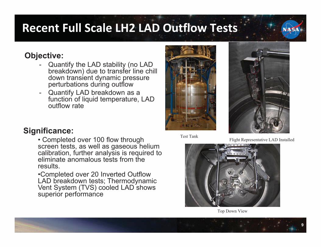
Objective:- Quantify the LAD stability (no LAD
breakdown) due to transfer line chill down transient dynamic pressure perturbations during outflow
- Quantify LAD breakdown as a function of liquid temperature, LAD outflow rate
Significance:• Completed over 100 flow through screen tests, as well as gaseous helium calibration, further analysis is required to eliminate anomalous tests from the results.•Completed over 20 Inverted Outflow LAD breakdown tests; Thermodynamic Vent System (TVS) cooled LAD shows superior performance
Flight Representative LAD Installed
Top Down View
Test Tank
Recent�Full�Scale�LH2�LAD�Outflow�Tests

10
Hardware Configuration- Flow-through-screen hardware mounted on test tank lid- 2 screens mounted in series (450x2750, 325x2300)- Flow routed vertically upward - Screens spaced out to overcome entrance effects @ highest flow rates @ second screen-Multiple DPTs for each screen to cover flow range-2 Venturi flow meters (FMs) used to measure flow-Both screens passed pretest Isopropyl Alcohol (IPA) bubble point test
450x2750
325x23002” OD x 0.875” ID
Flow�through�Screen�Research�Hardware

11
Temperature�Dependence�of��PFTS
• All data is for exact same 325x2300 screen sample• Our Ghe and LH2 data bound the single Armour and Cannon (A&C) curve fit to historical data
– Important to note that A&C prediction based on multiple screen styles (square, Dutch Twill) and gases
• Evidence that �P FTS may be temperature dependent (higher flow losses at LH2 temps due to possible screen shrinkage)
LH2, 24KLOX, 91KGHe, 296KModel, LH2Model, LOXModel, GHeHistorical
0.1
1
10
100
1000
104
0.01 0.1 1 10 100 1000
Fric
tion
Fact
or
Reynolds Number
Historical ModelHistorical Model, +1sdHistorical Model, -1sdLH2 ModelLH2 Model, +1sdLH2 Model, -1sdLH2 Data
0.1
1
10
10 100
Fric
tion
Fact
orReynolds Number

12
325x2300�TVS�Cooled�LAD
• From previous LOX, LCH4, LH2 bubble point tests, cooling the liquid at the screen lowers T, increases �, increases �PBP
• Gain in �PBP should translate into lower breakdown heights
• Triangular backed– Room for heat exchanger– Match hydraulic diameters
• Perforated plate backed screens – Enhanced wicking – Added structural support
against launch loads– Cost: reduces to 63% screen
open area

13
325x2300�TVS�Cooled�LAD�Principle�of�Operation
• Small amount of fluid is drawn from the tank, expanded across a JT orifice (constant enthalpy), thus cooled and circulated through the flight-like LAD as counterflow HEX to cool the fluid inside the LAD
• HEX designed to flash inside cooling coil inside LAD
• Measure DPT across JT, dTacross TVS
• LAD originally designed to cool LH2 inside channel 6oR @ 50 psia saturated liquid at a JT flow rate of ~0.0025 lbm/s (< 6.67% of lowest LAD outflow rate) SD28 (out)
SD29 (in)
14
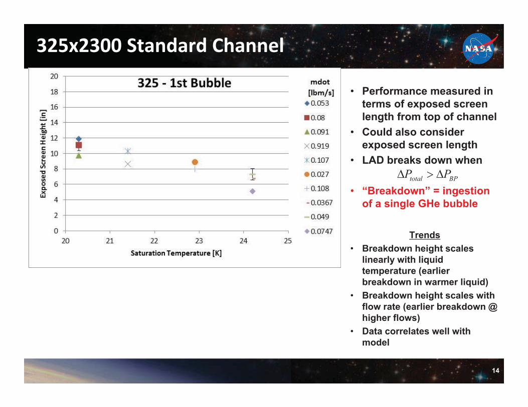
325x2300�Standard�Channel
total BPP P� � �
• Performance measured in terms of exposed screen length from top of channel
• Could also consider exposed screen length
• LAD breaks down when
• “Breakdown” = ingestion of a single GHe bubble
Trends• Breakdown height scales
linearly with liquid temperature (earlier breakdown in warmer liquid)
• Breakdown height scales with flow rate (earlier breakdown @ higher flows)
• Data correlates well with model

15
325x2300�Flight�Channel
Trends• Breakdown height scales with
liquid temperature (earlier breakdown in warmer liquid)
• Breakdown height scales inversely with flow rate (later breakdown @ higher flows)
• Data doesn’t correlates well with model
• TVS cooling flattens temperature dependence
• Perforated plate enhances wicking
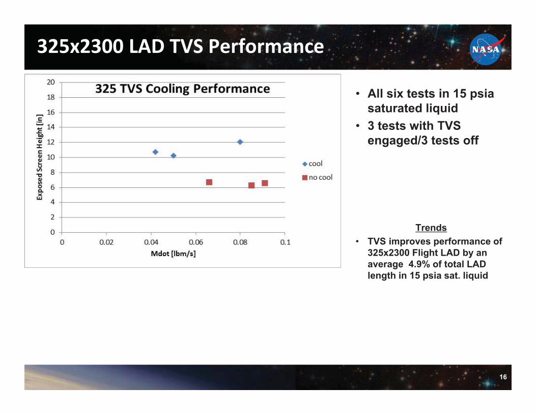
16
325x2300�LAD�TVS�Performance
• All six tests in 15 psiasaturated liquid
• 3 tests with TVS engaged/3 tests off
Trends• TVS improves performance of
325x2300 Flight LAD by an average 4.9% of total LAD length in 15 psia sat. liquid

17
Cryogenic�Bubble�Point�Pressure�Model
• Model determines static bubble point pressure for any screen, liquid, operating temperature and pressure, and pressurantgas type and temperature
• Model anchored to data (semi-analytical, semi-empirical)
• Accounts for:– Updated surface tension model– Temperature dependent pore diameter– Differences between pressurization schemes– Effect of subcooling the liquid– Effect of raising the pressurant gas temperature (relative
to liquid)
– n1, n2, n3, constants
� � � � � � � � � � � �1 2 34 cos, , , , 1 1SAT GAS
BP gasP REF REF
P P T T TP screen T P T n gas T n gas n gasD T P T� � � �
� � � � �� �� �
450x2750,�Liquid�Hydrogen� �PBP [Pa]

18
Inverted�Outflow�Data�vs.�Model
1FTS
C
PA
� �
• 325 TVS cooled outperforms 325, despite post-test degraded performance in IPA
• Disparity between data and model due to:
1. % area in FTS term
less flow area = more �PFTS� shift the data up 2. Degradation in performance from pre to post IPA tests

19
National Aeronautics and Space AdministrationNational Aeronautics and Space Administration
Findings and RecommendationsFindings and Recommendations
19

20
Summary of Results – LADs
1. Bubble point scales with the mesh of the screen for 325x2300 and 450x2750 screens.- 450 buys us 27% margin over 325 => higher flow rates during transfer- Pore diameter is both screen and temperature dependent
2. Bubble point scales with the surface tension of the liquid3. Ghe pressurization = gain factor; GH2 pressurization = degradation factor4. �PFTS is temperature dependent, as is the bubble point pressure
- �PFTS,450 < �PFTS, 325 . �PBP,450 > �PBP,325 . Hints at existence of optimized mesh for low surface tension liquid acquisition. (desire for flight is highest for �PBP for lowest �PFTS).
5. Frictional and Dynamic pressure losses also higher than anticipated @ LH2 temps.6. Inverted vertical outflow breakdown point dominated by liquid temp; second order dependence on liquid outflow rate
- TVS cooling always improves performance (cooling supports higher outflow rates)- Subcooling + pressurizing w/ GHe always improves performance (9% in 15 psiasaturated liquid )
21
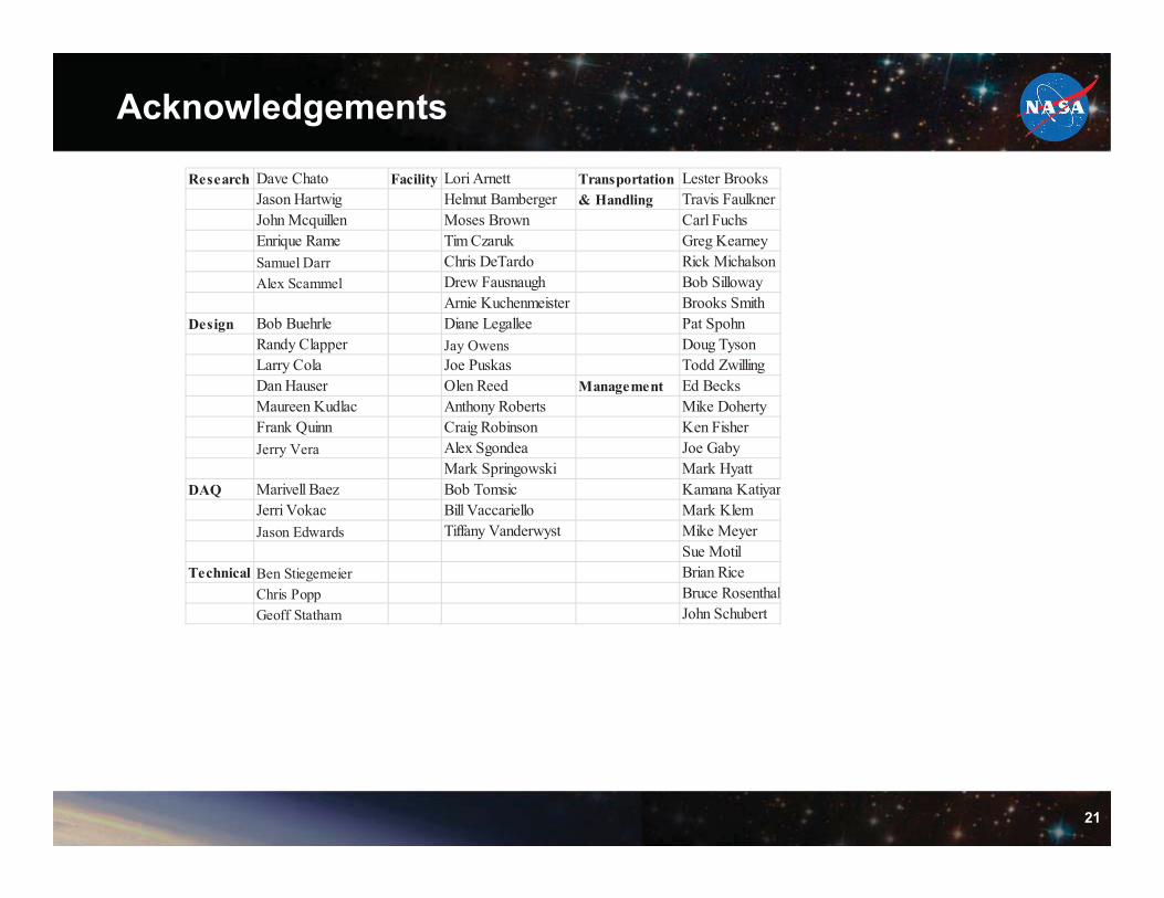
Acknowledgements
Research Dave Chato Facility Lori Arnett Transportation Lester BrooksJason Hartwig Helmut Bamberger & Handling Travis FaulknerJohn Mcquillen Moses Brown Carl FuchsEnrique Rame Tim Czaruk Greg KearneySamuel Darr Chris DeTardo Rick MichalsonAlex Scammel Drew Fausnaugh Bob Silloway
Arnie Kuchenmeister Brooks SmithDesign Bob Buehrle Diane Legallee Pat Spohn
Randy Clapper Jay Owens Doug TysonLarry Cola Joe Puskas Todd ZwillingDan Hauser Olen Reed Management Ed BecksMaureen Kudlac Anthony Roberts Mike DohertyFrank Quinn Craig Robinson Ken FisherJerry Vera Alex Sgondea Joe Gaby
Mark Springowski Mark HyattDAQ Marivell Baez Bob Tomsic Kamana Katiyar
Jerri Vokac Bill Vaccariello Mark KlemJason Edwards Tiffany Vanderwyst Mike Meyer
Sue MotilTechnical Ben Stiegemeier Brian Rice
Chris Popp Bruce RosenthalGeoff Statham John Schubert