cisco hybrid cloud solution for it capacity augmentation
TRANSCRIPT

Cisco Hybrid Cloud Solution for IT Capacity Augmentation
June 4, 2015
Building Architectures to Solve Business Problems

2
Cisco and the Cisco logo are trademarks or registered trademarks of Cisco and/or its affiliates in the U.S. and other countries. To view a list of Cisco trademarks, go to this URL: www.cisco.com/go/trademarks. Third-party trademarks mentioned are the property of their respective owners. The use of the word partner does not imply a partnership relationship between Cisco and any other company. (1110R)
THE SOFTWARE LICENSE AND LIMITED WARRANTY FOR THE ACCOMPANYING PRODUCT ARE SET FORTH IN THE INFORMATION PACKET THAT SHIPPED WITH THE PRODUCT AND ARE INCORPORATED HEREIN BY THIS REFERENCE. IF YOU ARE UNABLE TO LOCATE THE SOFTWARE LICENSE OR LIMITED WARRANTY, CONTACT YOUR CISCO REPRESENTATIVE FOR A COPY.
The Cisco implementation of TCP header compression is an adaptation of a program developed by the University of California, Berkeley (UCB) as part of UCB’s public domain version of the UNIX operating system. All rights reserved. Copyright © 1981, Regents of the University of California.
NOTWITHSTANDING ANY OTHER WARRANTY HEREIN, ALL DOCUMENT FILES AND SOFTWARE OF THESE SUPPLIERS ARE PROVIDED “AS IS” WITH ALL FAULTS. CISCO AND THE ABOVE-NAMED SUPPLIERS DISCLAIM ALL WARRANTIES, EXPRESSED OR IMPLIED, INCLUDING, WITHOUT LIMITATION, THOSE OF MERCHANTABILITY, FITNESS FOR A PARTICULAR PURPOSE AND NONINFRINGEMENT OR ARISING FROM A COURSE OF DEALING, USAGE, OR TRADE PRACTICE.
IN NO EVENT SHALL CISCO OR ITS SUPPLIERS BE LIABLE FOR ANY INDIRECT, SPECIAL, CONSEQUENTIAL, OR INCIDENTAL DAMAGES, INCLUDING, WITHOUT LIMITATION, LOST PROFITS OR LOSS OR DAMAGE TO DATA ARISING OUT OF THE USE OR INABILITY TO USE THIS MANUAL, EVEN IF CISCO OR ITS SUPPLIERS HAVE BEEN ADVISED OF THE POSSIBILITY OF SUCH DAMAGES.
Cisco Hybrid Cloud Solution for IT Capacity Augmentation
Service Provider Segment
© 2015 Cisco Systems, Inc. All rights reserved.

C O N T E N T S
Preface iii
Audience iii
C H A P T E R 1 Introduction 1-1
Intercloud Fabric Overview 1-2
C H A P T E R 2 Hybrid Cloud Use Cases 2-1
Workload Offloading 2-1
Distributed Workload 2-2
Planned Peak Capacity 2-2
Applications Used within Use Cases 2-2
C H A P T E R 3 Design Overview 3-1
Cisco Intercloud Fabric for Business 3-1
Cisco Intercloud Fabric Director 3-2
Self-Service IT Portal and Service Catalog 3-2
Cisco Intercloud Fabric Secure Extension 3-3
Cisco Intercloud Fabric Core Services 3-3
Cisco Intercloud Fabric Firewall Services 3-3
Cisco Intercloud Fabric Routing Services 3-4
Cisco Secure Intercloud Fabric Shell 3-4
VM Portability and Mobility 3-4
Cisco Intercloud Fabric for Providers 3-5
Cisco Intercloud Fabric Provider Platform 3-5
C H A P T E R 4 Implementation and Configuration 4-1
Initial Intercloud Fabric Deployment within the Enterprise 4-1
Deployment of the IcfCloud Link (IcfCloud) 4-4
Cloud VMs (cVM), Virtual Data Centers (vDC), and Categories 4-5
Intercloud Fabric Implementation for Cisco Powered Provider 4-7
Intercloud Fabric Implementation for Amazon 4-8
AWS ICF Router Implementation 4-9
Deploying ICF Router 4-9
iCisco Hybrid Cloud Solution for IT Capacity Augmentation

Contents
Enabling Inter-VLAN Routing 4-12
Extended Routing and NAT Configuration 4-13
ICF Firewall Implementation into AWS 4-18
Create ICF Firewall Data Interface Port-Profile 4-18
Create ICF Firewall Data Interface IP Pool 4-19
Add ICF Firewall Services to the IcfCloud 4-20
Using PNSC to Configure and Deploy the ICF Firewall Service 4-21
Add (Optional) vZone(s) 4-26
Create Security Profile(s) 4-28
Create Firewall Service Paths 4-29
Associate Service Paths to Port Profiles 4-30
ICF Firewall Rule Verification with a Syslog Server 4-32
Configuring an ICF Firewall 4-33
Intercloud Fabric Implementation 4-35
Intercloud Fabric Implementation for Azure 4-35
Intercloud Fabric Implementation for Use Case 1, 3-Tier Offloading 4-36
Intercloud Fabric Implementation for Use Case 2, Distributed Work Load 4-37
Intercloud Fabric Implementation for Use Case 3, Planned Peak Capacity 4-38
Use Case Testing and Results 4-39
3-Tier Offloading to Azure 4-40
3-Tier Offloading to Cisco Powered Provider 4-40
3-Tier Offloading to AWS 4-41
Distributed Workload with Azure 4-42
Distributed Workload with AWS 4-43
Planned Peak Capacity with Cisco Powered Provider 4-43
A P P E N D I X A Recommended Practices and Caveats A-1
Recommended Practices A-1
Application Deployment Validation for Hybrid Environments A-1
Network Planning for Cisco Intercloud Fabric A-1
Naming Convention A-2
High Level Security Recommendations A-2
Caveats A-3
A P P E N D I X B Technical References B-1
A P P E N D I X C Terms and Acronyms C-1
iiCisco Hybrid Cloud Solution for IT Capacity Augmentation

Preface
This document provides guidance and best practices for deploying Cisco Hybrid Cloud Solution for IT Capacity Augmentation use cases, allowing customers to seamlessly extend the enterprise network and security, and manage workloads on different Public Clouds, such as AWS, Azure, and Cisco Powered Provider.
The design has undergone an intensive test program, and the goal of this validated solution is to minimize the TCO (Total Cost of Ownership) of a customer looking to deploy Intercloud Fabric for Business, by accelerating and simplifying its deployment. The focus is on Intercloud Fabric for Business and the end-to-end solution validation, in the context of Capacity Augmentation use case and three specific sub-use cases:
1. Generic Workload Offloading (with and without network and security services)
2. Distributed Generic Workload (with and without network and security services)
3. Planned Peak Capacity
This guide supplements the general Cisco Intercloud Fabric document.
AudienceThis document is intended for, but not limited to, IT managers or architects, sales engineers, field consultants, professional services, Cisco channel partner engineering staff, and all customers who wish to understand further how to seamlessly place and manage their virtualized workloads in a hybrid cloud environment.
iiiCisco Hybrid Cloud Solution for IT Capacity Augmentation

ivCisco Hybrid Cloud Solution for IT Capacity Augmentation
Cisco
C H A P T E R 1
IntroductionThe Cisco Validated Design (CVD) for Hybrid Cloud Solution for IT Capacity Augmentation, helps customers accelerate the implementation of Intercloud Fabric solution, and achieve a faster and more flexible response to business needs, addressing the following potential challenges of hybrid cloud implementation:
• Workloads placement across heterogeneous Private and Public Clouds
• Secure extension from Private Cloud to Public Cloud
• Unified management and networking to move workloads across clouds
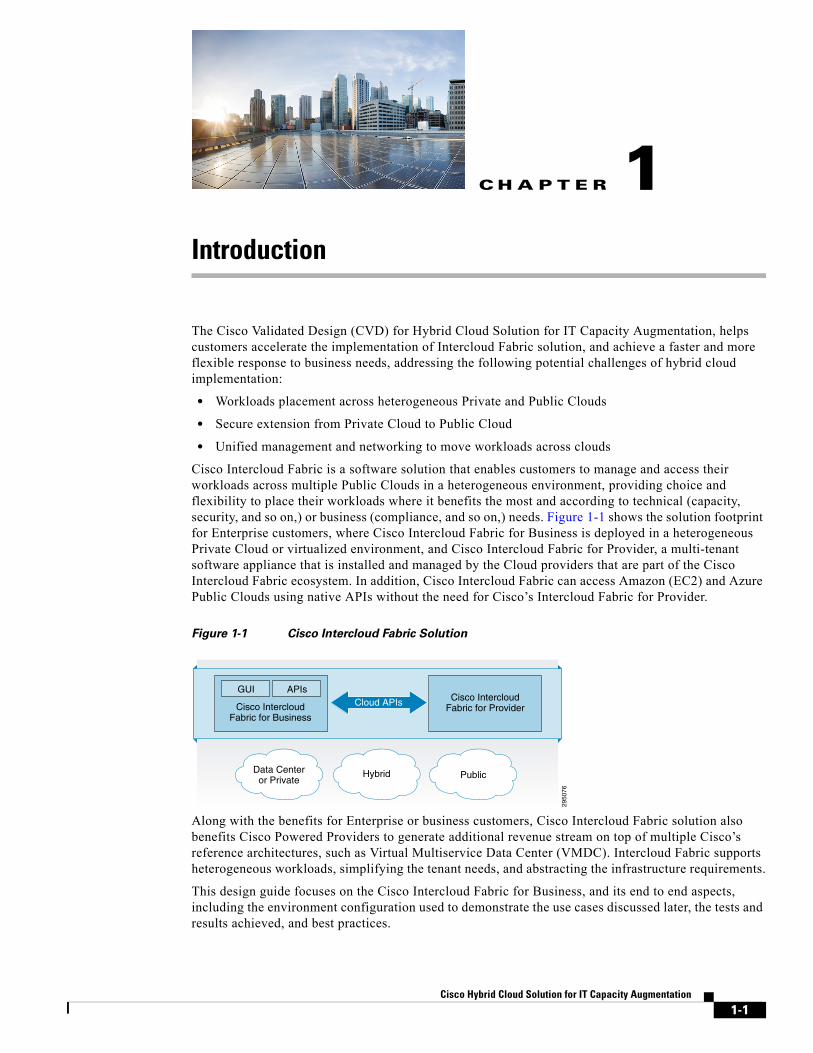
Cisco Intercloud Fabric is a software solution that enables customers to manage and access their workloads across multiple Public Clouds in a heterogeneous environment, providing choice and flexibility to place their workloads where it benefits the most and according to technical (capacity, security, and so on,) or business (compliance, and so on,) needs. Figure 1-1 shows the solution footprint for Enterprise customers, where Cisco Intercloud Fabric for Business is deployed in a heterogeneous Private Cloud or virtualized environment, and Cisco Intercloud Fabric for Provider, a multi-tenant software appliance that is installed and managed by the Cloud providers that are part of the Cisco Intercloud Fabric ecosystem. In addition, Cisco Intercloud Fabric can access Amazon (EC2) and Azure Public Clouds using native APIs without the need for Cisco’s Intercloud Fabric for Provider.
Figure 1-1 Cisco Intercloud Fabric Solution
Along with the benefits for Enterprise or business customers, Cisco Intercloud Fabric solution also benefits Cisco Powered Providers to generate additional revenue stream on top of multiple Cisco’s reference architectures, such as Virtual Multiservice Data Center (VMDC). Intercloud Fabric supports heterogeneous workloads, simplifying the tenant needs, and abstracting the infrastructure requirements.
This design guide focuses on the Cisco Intercloud Fabric for Business, and its end to end aspects, including the environment configuration used to demonstrate the use cases discussed later, the tests and results achieved, and best practices.
2950
76
Data Centeror Private PublicHybrid
Cisco IntercloudFabric for Business
Cisco IntercloudFabric for Provider
GUI APIsCloud APIs
1-1Hybrid Cloud Solution for IT Capacity Augmentation

Chapter 1 Introduction Intercloud Fabric Overview
The solution validation includes the discussion of Capacity Augmentation, helping customers to understand how Cisco Intercloud Fabric is leveraged to support such scenarios, and to help IT departments support their line of businesses. Within Capacity Augmentation, this breaks down into three sub-use cases which are as following:
• Workload Offloading (with and without network and security services)—Workload Offloading use cases focus on the offload of a complete 3-tier application (Web/App/DB services) from the Enterprise into the Service Provider Cloud. In some Service Provider environments, the Enterprise would deploy firewall, load balancing, and routing services for data traffic being extended into the cloud. Test cases for both, with and without services, were executed.
• Distributed Workload (with and without network and security services)—Web front end services of a 3-tier application are deployed and verified in the Service Provider Cloud, while the application and database services for the application reside in the Enterprise Data Center. In some Service Provider environments, the Enterprise would deploy firewall, load balancing, and routing services for the web traffic that is extended into the cloud. Test cases for both, with and without services, were executed.
• Planned Peak Capacity—In the Planned Peak Capacity use case, Enterprise customers can use Service Provider Cloud resources temporarily to burst their workloads into the Public Cloud to meet the seasonal demands. The resources are released/decommissioned in the Public Cloud when high demand processing finishes.
Intercloud Fabric OverviewThe Hybrid Cloud solution objective is to unify all clouds and provide ubiquitous end user access to any services in the cloud. For example, the end users in the Private Cloud or virtualized environments have access to services in the Virtual Private Cloud (vPC) or Public Cloud as if accessing the resources in the Private Cloud. From here, both vPC and Public Cloud are referred to as “Provider Cloud”, and both Private Cloud or virtualized environment are referred to as “Private Cloud”.
The Intercloud Fabric Director (ICFD) Administrative Interface or the ICFD user interface is used for the provisioning of applications and compute resources in the Provider Cloud.
These applications and compute resources can either be instantiated in the Service Provider Cloud either by the Administrator or a user interface, or if permitted, existing resources within the Enterprise environment may be offloaded to the Service Provider Cloud.
Note When this document makes reference to application or workload, it means VMs (Virtual Machines), which host Enterprise applications and workloads. At this moment the unit of operation of Cisco Intercloud Fabric is a VM.
ICF utilizes existing Enterprise resources such as DHCP, SMTP, and AD to secure and verify that existing resources are available for provisioning and that the role of the person doing the provisioning has the correct credentials and authority to provision those resources.
The ICF solution provides essential automated management and orchestration that allows organizations to control and manage cloud-based services transparently throughout their life cycles. This covers a diverse range of cloud deployments that flexibly scale from test and development to production workloads, and from initial cloud pilots to large-scale Enterprise-wide initiatives, for delivering maximum value to customers.
1-2Cisco Hybrid Cloud Solution for IT Capacity Augmentation

Cisco
C H A P T E R 2
Hybrid Cloud Use CasesAs Enterprises are adopting both the Private and Provider Clouds (Public Clouds), they want the flexibility to place their workloads in either of these two clouds based on their needs, as well as company policy and/or compliance requirements. As the Enterprise business grows rapidly and requires additional compute resources, Enterprise IT wants to take advantage of resources in the Provider Cloud rather than building out additional Data Centers or adding additional compute resources in their Private Cloud. Also, in peak season, Enterprises require placing some of their workloads in the Provider Cloud to meet the demands but keep their sensitive data in the Private Cloud. However, if the enterprise is connecting to Provider Cloud via WAN, latency and bandwidth (BW) costs maybe a concern since most applications have strict latency requirements. It is very common to find Enterprises Data Center or Private Cloud co-located with Provider Cloud and therefore latency between application servers and tiers is not a concern.
This design guide emphasizes Capacity Augmentation use cases and sub-use cases that include Workload Offloading, Distributed Workload, and Planned Peak Capacity.
Workload OffloadingThe Workload Offloading use case, with or without network and security services, focuses on the ability of Intercloud Fabric to help customers to use additional capacity of Provider Clouds to offload an existing application running in the Private Cloud, while extending network and security policies. The use case focuses on the offload of a complete 3-tier application (Web/App/DB services) from the Enterprise into the Provider Cloud. In some Service Provider environments, the Enterprise deploys firewall, load balancing, and routing services for data traffic extended into the cloud. Test cases for both, with and without services, were executed.
Note Intercloud Fabric is not positioned as a migration tool by itself. It includes an offload capability for the move of the VM and the seamless extension of the network and security to the Provider Cloud, while keeping the control point at the Enterprise or business customer. For one-time migration purposes where there is no need to extend the network and security or maintain the control from a portal in the Enterprise, Cisco recommends other tools from partners.
2-1Hybrid Cloud Solution for IT Capacity Augmentation

Chapter 2 Hybrid Cloud Use Cases Distributed Workload
Distributed WorkloadIn a hybrid cloud scenario, applications are eventually deployed in a distributed fashion, in dispersed locations. Intercloud Fabric enables customers to take advantage of the ability to manage multiple Provider Clouds as a seamless extension of the Private Cloud, which makes it easier for distributed applications. This powerful ability creates the need for being mindful of requirements prior to distributing the application.
As part of the Distributed Workload use case, with or without network and security services, a web front end services of a 3-tier application is deployed and verified in the Provider Cloud, while the application and database services for the application reside in the Enterprise Data Center. In some Service Provider environments, the Enterprise deploys the firewall, load balancing, and routing services for the web traffic that extends into the cloud. Test cases for both, with and without services, were executed.
Planned Peak CapacityIn the Planned Peak Capacity use case, Enterprise customers use Service Provider Cloud resources to temporarily burst their workloads to meet any seasonal demands. The resources are released/decommissioned in the Provider Cloud when high-demand processing finishes.
Cisco Intercloud Fabric manages the creation and access to the VMs in the Provider Clouds, extending the network and Enterprise configured security policies, all while managing the life-cycle of the cloud positioned VM.
Cisco Intercloud Fabric exposes APIs on the business side that can be used by monitoring systems and/or cloud platforms to trigger instantiation of additional VMs to a certain application with configuration of the new servers and services as part of such application. This design guide does not demonstrate APIs or 3rd party tools.
Applications Used within Use CasesTwo 3-Tier applications were used throughout the testing and included a deployment of Microsoft SharePoint and a WAMP (Windows Apache MySQL PHP) placement. Each of these were deployed to the different provider environments, with some differentiation based on availability of services (Table 2-1).
Further breakdown of these subcomponents is shown in Table 2-2 and Table 2-3, with the database resource varying due to provider OS support differences.
Table 2-1 Service Providers, Services and Applications
Provider Services Application
Amazon EC2 ICF Firewall, ICF Router, HA Proxy1
1. HAProxy = Open Source Load Balancer
3 Tier WAMP Stack / 3 Tier SharePoint
Microsoft Azure HA Proxy 3 Tier WAMP Stack / 3 Tier SharePoint
Cisco Powered Provider (ICFPP) HA Proxy 3 Tier WAMP Stack / 3 Tier SharePoint
2-2Cisco Hybrid Cloud Solution for IT Capacity Augmentation

Chapter 2 Hybrid Cloud Use Cases Applications Used within Use Cases
An open source load balancer application was deployed in the Enterprise and, depending on the use case, was offloaded to the service Provider Cloud to load balance and monitor traffic destined to each of the web front-end servers. The HAProxy application was installed on both a Red Hat Linux version 6.3 and CentOS version 6.3 virtual machine. It was deployed into the Enterprise’s VMware environment. For more information regarding HAProxy and its functionality refer to the HAProxy web site.
Table 2-2 SharePoint 3-Tier Application
Quantity Resource OS Component
2-4 Web Front End (WFE) Windows 2008 R2 SP1 MS IIS
1 Application (App) Windows 2008 R2 SP1 MS SharePoint
2 Database (DB) Windows 2008 R2 SP1 MS SQL Cluster
Table 2-3 WAMP 3-Tier Application
Quantity Resource OS Component
2 Web Front End (WFE) Windows 2008 R2 SP1 MS IIS
1 Application (App) Red Hat Enterprise Linux 6.3 Tomcat/PHP
1 Database (DB) CentOS 6.3/RHEL 6.3 MySQL
2-3Cisco Hybrid Cloud Solution for IT Capacity Augmentation

Chapter 2 Hybrid Cloud Use Cases Applications Used within Use Cases
2-4Cisco Hybrid Cloud Solution for IT Capacity Augmentation

Cisco
C H A P T E R 3
Design OverviewThe Cisco Intercloud Fabric solution helps customers to seamlessly extend their network and security policies from Private Cloud to Provider Cloud, while maintaining the point of control in the Enterprise, for example, as in an IT department. This section discusses solution design points.
Figure 3-1 shows the overall high-level design for the Cisco Intercloud Fabric solution. It is important to understand aspects of the solution architecture.
Figure 3-1 Cisco Intercloud Fabric Solution Overview
The Cisco Intercloud Fabric architecture provides two product configurations to address the following two consumption models:
• Cisco Intercloud Fabric for Business (focus of this design guide)
• Cisco Intercloud Fabric for Providers
Cisco Intercloud Fabric for BusinessCisco Intercloud Fabric for Business is intended for Enterprise customers who want to be able to transparently extend their Private Cloud into Public Cloud environments, while keeping the same level of security and policy across environments. Cisco Intercloud Fabric for Business consists of the following components:
• Cisco Intercloud Fabric Director
• Cisco Intercloud Fabric Secure Fabric
Cisco Intercloud Fabric for Business
IT AdminsEnd Users
2950
77
Secure Network Extension
Cisco IntercloudFabric Director
End User and IT AdminPortal Workload andFabric Management
Cisco IntercloudFabric Services
VM Manager
Cisco IntercloudFabric for Providers
Cisco IntercloudFabric Provider
Platform
ICF Secure Shell
Cisco PrivateCloud Services
Data Center/Private Cloud
ProviderCloud
VM VM VM VM
3-1Hybrid Cloud Solution for IT Capacity Augmentation

Chapter 3 Design Overview Cisco Intercloud Fabric for Business
Cisco Intercloud Fabric DirectorWorkload management in a hybrid environment goes beyond the capability to create and manage virtual services in a Private or Public and Provider Cloud and network extension. Both capabilities are part of the overall hybrid cloud solution, that also needs to provide different types of services, such as policy capabilities (placement, quotas, and so on,), capabilities to manage workloads in heterogeneous environments, and other capabilities as discussed here.
Cisco Intercloud Fabric Director (ICFD) provides to the end user and IT administrator a seamless experience to create and manage workloads across multiple clouds. It is the single point of management and consumption for hybrid cloud solutions.
Heterogeneous cloud platforms are supported by Cisco ICFD in the Private Cloud, which operationally unifies workload management in a cloud composed of different cloud infrastructure platforms, such as VMware vSphere and vCloud, Microsoft Hyper-V and System Center Virtual Machine Manager (SCVMM), OpenStack, and CloudStack. This unification provides a holistic workload management experience and multiple options for cloud infrastructure platforms for the customers. Cisco ICFD provides the required software development kit (SDK) and APIs to integrate with the various cloud infrastructure platforms.
Cisco ICFD exposes northbound APIs that allow customers to programmatically manage their workloads in the hybrid cloud environment or to integrate with their management system of choice, which allows more detailed application management that includes policy and governance, application design, and other features.
Future releases of Cisco ICFD plan to include enhanced services that differentiate the Cisco Intercloud Fabric solution, such as bare-metal workload deployment in a hybrid cloud environment and an enhanced IT administrative portal with options to configure disaster recovery and other services.
Self-Service IT Portal and Service CatalogThe Cisco ICFD self-service IT portal makes it easy for IT administrators to manage and consume hybrid cloud offers, and for the end users to consume services. For end users, Cisco ICFD provides a service catalog that combines offers from multiple clouds and a single self-service IT portal for hybrid workloads.
For IT administrators, Cisco ICFD has an IT administrative portal from which administrators can perform the following administrative tasks:
• Configure connection to Public and Enterprise Private Clouds.
• Configure roles and permissions and Enterprise Lightweight Directory Access Protocol (LDAP) integration.
• Add and manage tenants.
• Configure basic business policies that govern workload placement between the Enterprise and Public Clouds; advanced policies are available in the management layer.
• Customize portal branding.
• Monitor capacity and quota use.
• Browse and search the service catalog and initiate requests to provision and manage workloads in the cloud.
• View the workload across multiple clouds and offloaded workloads as necessary.
• Manage user information and preferences.
3-2Cisco Hybrid Cloud Solution for IT Capacity Augmentation

Chapter 3 Design Overview Cisco Intercloud Fabric Core Services
• Configure catalog and image entitlement.
• Configure virtual machine template and image import, categorization, and entitlement.
• Perform Cisco Intercloud Fabric Secure Extension management.
• Future capabilities are added through the end-user or IT administrative portal.
Cisco Intercloud Fabric Secure ExtensionAll data in motion is cryptographically isolated and encrypted within the Cisco Intercloud Fabric Secure Extender. This data includes traffic exchanged between the Private and Public Clouds (site-to-site) and the virtual machines running in the cloud (VM-to-VM). A Datagram Transport Layer Security (DTLS) tunnel is created between endpoints to more securely transmit this data. DTLS is a User Datagram Protocol (UDP)-based, highly secure transmission protocol. The Cisco Intercloud Fabric Extender always initiates the creation of a DTLS tunnel.
Cisco Intercloud Fabric Core ServicesCisco Intercloud Fabric includes a set of services that are crucial for customers to successfully manage their workloads across the hybrid cloud environment. These services are identified as Intercloud Fabric Core Services and are as follows:
• Cloud Security—security enforcement for site to site and VM to VM communications.
• Networking—switching, routing and other advanced network-based capabilities.
• VM Portability—VM format conversion and mobility.
• Management and Visibility—hybrid cloud monitoring capabilities.
• Automation—VM life-cycle management, automated operations and programmatic API.
Future releases of Cisco Intercloud Fabric plan to include an extended set of services, including support for 3 rd party appliances.
Cisco Intercloud Fabric Firewall ServicesIn traditional Data Center deployments, virtualization presents a need to secure traffic between virtual machines; this traffic is generally referred to as east-west traffic. Instead of redirecting this traffic to the edge firewall for lookup, Data Centers can handle the traffic in the virtual environment by deploying a zone-based firewall. Cisco Intercloud Fabric includes a zone-based firewall that is deployed to provide policy enforcement for communication between virtual machines and to protect east-west traffic in the provider Cloud. The virtual firewall is integrated with Cisco Virtual Path (vPath) technology, which enables intelligent traffic steering and service chaining. The main features of the zone-based firewall include:
• Policy definition based on network attributes or virtual machine attributes such the virtual machine name.
• Zone-based policy definition, which allows the policy administrator to partition the managed virtual machine space into multiple logical zones and write firewall policies based on these logical zones.
• Enhanced performance due to caching of policy decisions on the local Cisco vPath module after the initial flow lookup process.
3-3Cisco Hybrid Cloud Solution for IT Capacity Augmentation

Chapter 3 Design Overview Cisco Intercloud Fabric Core Services
Cisco Intercloud Fabric Routing ServicesCisco Intercloud Fabric Secure Extender provides a Layer 2 (L2) extension from the Enterprise Data Center to the provider Cloud. To support Layer 3 (L3) functions without requiring traffic to be redirected to the Enterprise Data Center, Cisco Intercloud Fabric also includes a virtual router. The virtual router is based on proven Cisco IOS® XE Software and runs as a virtual machine in the provider Cloud. The router deployed in the cloud by Intercloud Fabric serves as a virtual router and firewall for the workloads running in the provider Cloud and works with Cisco routers in the Enterprise to deliver end-to-end Cisco optimization and security. The main functions provided by the virtual router include:
• Routing between VLANs in the provider Cloud.
• Direct access to cloud virtual machines.
• Connectivity to Enterprise branch offices through a direct VPN tunnel to the Service Provider's Data Center.
• Access to native services supported by a Service Provider: for example, use of Amazon Simple Storage Service (S3) or Elastic Load Balancing services.
Cisco Secure Intercloud Fabric ShellCisco Secure Intercloud Fabric Shell (Secure ICF Shell) is a high-level construct that identifies a group of VMs and the associated Cloud Profiles, and it is designed to be portable and secure across clouds. A cloud profile includes the following configurations:
• Workload Policies—a set of policies created by the Enterprise IT Admin via Intercloud Fabric Director portal to define what networks are to extend, security enforcements to be applied to the workloads in the cloud, and other characteristics such as DNS configuration.
• Definition of the Site-to-Site and VM to VM Secure Communication—IT Admins manage, enable, or disable secure tunnel configurations between the Private and Public Clouds and/or between the VMs in the cloud.
• VM Identity—Intercloud Fabric creates an identity for all the VMs that it manages to ensure only trusted VMs are allowed to participate of the networks extended to the cloud, communicate to other VMs in the same circle of trust in the Public Cloud, or to communicate to other VMs in the Private Cloud.
• Cloud VM Access Control—Intercloud Fabric helps to control the access to the cloud VMs via the secure tunnel established between Private and Public Clouds, or directly via the VM Public IP defined and managed via Intercloud Fabric.
VM Portability and MobilityCisco Intercloud Fabric allows customers to offload VMs from Enterprise virtualized Data Centers to the cloud, and back from the cloud to the Data Center. The abstraction of the underlying layers allows offloading to happen seamlessly regardless of the source and target environments, as long as the environments are supported by Cisco ICF.
At the time of completion of this document, the mechanism that is supported allowed only cold offloading, which included offloading a VM from one point to another, shutting it down, importing it by Cisco ICF for image transformation, and then copying it to the destination, where it was powered on and accessed by the users.
3-4Cisco Hybrid Cloud Solution for IT Capacity Augmentation

Chapter 3 Design Overview Cisco Intercloud Fabric for Providers
The transformation process normalizes the required capabilities between different clouds, for example: a VM that is offloaded from VMware environment to AWS requires image conversion from vmdk to AMI, and when a VM is offloaded from AWS to a VMware-based Private Cloud, Cisco ICF converts from AMI to vmdk. All the operations to transform and normalize the workload when it is offloaded to the cloud and from the cloud, are performed in the Private Cloud, within Cisco ICFB.
Cisco does not position ICF as an offloading tool by itself, but as part of the solution to support portability and mobility of the workload, that customers can use it to choose where to place a VM as needed in a hybrid cloud environment. Others tools are better positioned for one-time offloading purposes.
Cisco Intercloud Fabric for ProvidersCisco Intercloud Fabric for Providers is intended for Provider Cloud environments, allowing their Enterprise customers to transparently extend their Private Cloud environments into the provider's Public Cloud, while keeping the same level of security and policy across cloud environments. There are two Cisco Intercloud Fabric offers for providers; those who offer managed services, or those targeted for Intercloud Fabric hybrid workloads. For Service Providers that want to offer managed services, Cisco Intercloud Fabric consists of the following components:
• Cisco Intercloud Fabric Director
• Cisco Intercloud Fabric Secure Fabric
• Cisco Intercloud Fabric Provider Platform
For Service Providers that want just to be a target for hybrid workloads, Cisco Intercloud Fabric consists of the following components:
• Cisco Intercloud Fabric Provider Platform
Cisco Intercloud Fabric Provider PlatformCisco Intercloud Fabric Provider Platform (ICFPP) simplifies and abstracts the complexity involved in working with a variety of Public Cloud APIs, and it enables cloud API support for Service Providers that currently do not have it. Cisco ICFPP provides an extensible adapter framework to allow integration with a variety of Provider Cloud infrastructure management platforms, such as OpenStack, Cloudstack, VMware vCloud Director, and virtually any other APIs that is integrated through an SDK provided by Cisco.
Currently, service providers have their own proprietary cloud APIs (Amazon Elastic Compute Cloud [EC2], Microsoft Windows Azure, VMware vCloud Director, OpenStack, and so on,), giving customers limited choices and no easy option to move from one provider to another. Cisco ICFPP abstracts this complexity and translates Cisco Intercloud Fabric API calls to different provider infrastructure platforms, giving customers the choice to move their workloads regardless of the cloud API exposed by the Service Provider.
Many Service Providers do not provide cloud APIs that Cisco Intercloud Fabric can use to deploy customers' workloads. One option for these providers is to provide direct access to their virtual machine managers' SDKs and APIs (for example, through VMware vCenter or Microsoft System Center), which exposes the provider environment and in many cases is not a preferred option for Service Providers because of security concerns, for example. Cisco ICFPP, as the first point of authentication for the customer cloud that allows it to consume Provider Cloud resources, enforces highly secure access to the provider environment and provides the cloud APIs that are required for service providers to be part of the provider ecosystem for Cisco Intercloud Fabric.
3-5Cisco Hybrid Cloud Solution for IT Capacity Augmentation

Chapter 3 Design Overview Cisco Intercloud Fabric for Providers
As the interface between the Cisco Intercloud Fabric from customers' cloud environments and provider clouds (Public and virtual Private Clouds), Cisco ICFPP provides a variety of benefits, as described below:
• Brings standardization and uniformity to cloud APIs, making it easier for Cisco Intercloud Fabric to consume cloud services from service providers that are part of the Cisco Intercloud Fabric ecosystem.
• Helps secure access to service providers' underlying cloud platforms.
• Limits the utilization rate per customer and tenant environment.
• Provides northbound APIs for service providers to integrate with existing management platforms.
• Supports multi-tenancy.
• Provides tenant-level resource monitoring.
• In the future, it helps build Cisco infrastructure-specific differentiation.
• In the future, support is provided for enterprises to deploy bare-metal workloads in the provider Cloud.
3-6Cisco Hybrid Cloud Solution for IT Capacity Augmentation
Cisco
C H A P T E R 4
Implementation and ConfigurationIntercloud Fabric for Business works with a growing number of provider options. The providers supported during this release are Amazon Web Services, Microsoft Azure, and Cisco Powered Provider Public Cloud. For more information refer to Installation and Upgrade Guides.
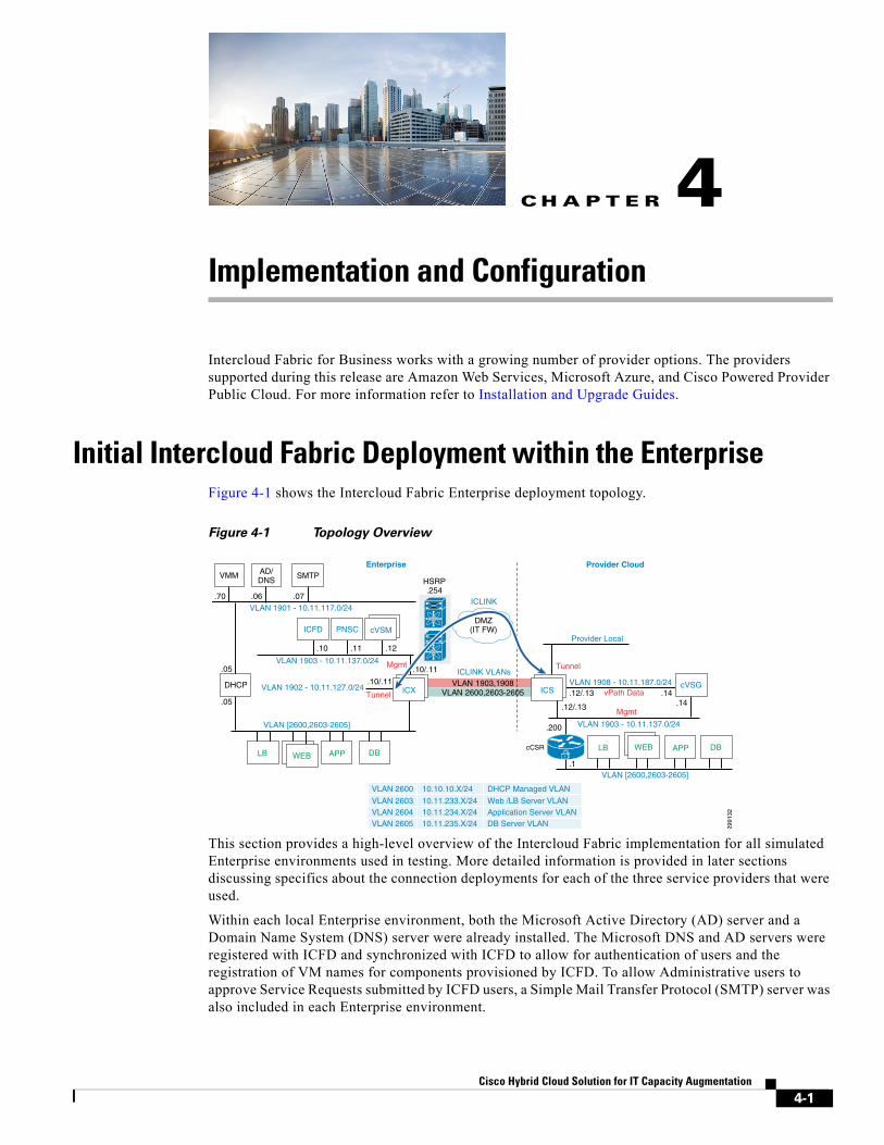
Initial Intercloud Fabric Deployment within the EnterpriseFigure 4-1 shows the Intercloud Fabric Enterprise deployment topology.
Figure 4-1 Topology Overview
This section provides a high-level overview of the Intercloud Fabric implementation for all simulated Enterprise environments used in testing. More detailed information is provided in later sections discussing specifics about the connection deployments for each of the three service providers that were used.
Within each local Enterprise environment, both the Microsoft Active Directory (AD) server and a Domain Name System (DNS) server were already installed. The Microsoft DNS and AD servers were registered with ICFD and synchronized with ICFD to allow for authentication of users and the registration of VM names for components provisioned by ICFD. To allow Administrative users to approve Service Requests submitted by ICFD users, a Simple Mail Transfer Protocol (SMTP) server was also included in each Enterprise environment.
HSRP.254
2991
32
Mgmt
Mgmt
AD/DNS
VMM SMTP
VLAN 1901 - 10.11.117.0/24
Provider Local.10 .11 .12
.06 .07.70
VLAN 2600,2603-2605VLAN 1903,1908
DMZ(IT FW)
Enterprise Provider Cloud
.10/.11
Tunnel
Tunnel
vPath Data.10/.11
VLAN 1903 - 10.11.137.0/24
VLAN 1908 - 10.11.187.0/24
VLAN 1903 - 10.11.137.0/24
ICLINK
ICLINK VLANs
VLAN 1902 - 10.11.127.0/24
VLAN [2600,2603-2605]
VLAN [2600,2603-2605]
.1
.12/.13
.14.12/.13.14
cCSR
.200
.1
.05
.05
VLAN 2600 10.10.10.X/24 DHCP Managed VLAN
VLAN 2603 10.11.233.X/24 Web /LB Server VLAN VLAN 2604 10.11.234.X/24 Application Server VLAN VLAN 2605 10.11.235.X/24 DB Server VLAN
ICFD PNSC cVSM
ICX ICSDHCP cVSG
APPAPP
DBDB
LBLB
WEBWEB
4-1Hybrid Cloud Solution for IT Capacity Augmentation

Chapter 4 Implementation and Configuration Initial Intercloud Fabric Deployment within the Enterprise
Note Approver SMTP functionality was not tested as part of this CVD.
As part of each Enterprise compute environment a Cisco Nexus 1000V, Virtual Distributed Switch (vDS), was used to provide L2 network connectivity between the various LAN segments in the Enterprise. Each compute environment consisted of one or more Cisco UCS Chassis and two B200-M2 server blades running either ESXi version 5.5.0 or 5.1.0. The compute layer was then connected to a network topology based on a Cisco Virtual Multi-Tenant Data Center (VMDC 2.2) design. Enterprise networks were configured as separate tenant containers (Virtual Routing Domains) within the same physical network. For more information related to the VMDC 2.2 network architecture refer to the VMDC2.2 Design Guide.
Note Refer to Appendix A, “Recommended Practices and Caveats” for more detailed information about the infrastructure.
For all test topologies, Intercloud Fabric Director was deployed using the OVA image downloaded from the Cisco web site into a VMware vSphere environment.
Before configuring ICFD OVA any further, after it deploys, it must be licensed. To install the license, log into the ICFD web interface as admin and select Administration > License (Figure 4-2).
Figure 4-2 Cisco Intercloud Fabric for Business Licensing
With the license submitted, begin the configuration of the Infrastructure components of Prime Network Services Controller (PNSC) and the Cloud Virtual Supervisor Module (cVSM). The Infrastructure wizard is started within ICFD under the first pull-down option of the Intercloud tab (Figure 4-3).
4-2Cisco Hybrid Cloud Solution for IT Capacity Augmentation
Chapter 4 Implementation and Configuration Initial Intercloud Fabric Deployment within the Enterprise
Figure 4-3 Cisco Intercloud Fabric Infrastructure Setup
Within the Infrastructure setup, configure the ICFD and register it to the local vCenter server representing that particular Enterprise environment.
The wizard then provisions either a single cVSM or redundant cVSMs for high availability (HA). For testing purposes, each Enterprise has a pair of Cisco UCS B-Series servers installed with VMware ESXi version 5.1 or 5.5. Using two, physical hosts permits a single cVSM distribution across each host to provide high availability.
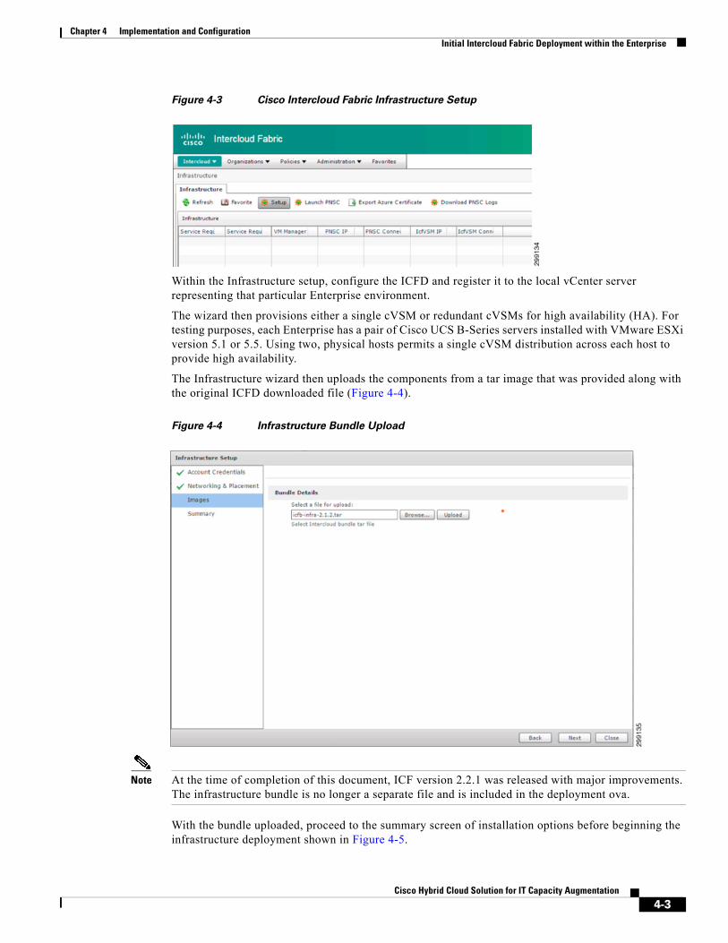
The Infrastructure wizard then uploads the components from a tar image that was provided along with the original ICFD downloaded file (Figure 4-4).
Figure 4-4 Infrastructure Bundle Upload
Note At the time of completion of this document, ICF version 2.2.1 was released with major improvements. The infrastructure bundle is no longer a separate file and is included in the deployment ova.
With the bundle uploaded, proceed to the summary screen of installation options before beginning the infrastructure deployment shown in Figure 4-5.
4-3Cisco Hybrid Cloud Solution for IT Capacity Augmentation
Chapter 4 Implementation and Configuration Initial Intercloud Fabric Deployment within the Enterprise
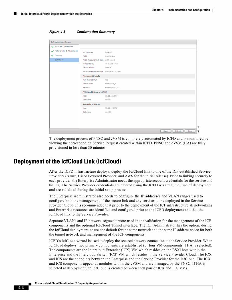
Figure 4-5 Confirmation Summary
The deployment process of PNSC and cVSM is completely automated by ICFD and is monitored by viewing the corresponding Service Request created within ICFD. PNSC and cVSM (HA) are fully provisioned in less than 30 minutes.
Deployment of the IcfCloud Link (IcfCloud)After the ICFD infrastructure deploys, deploy the IcfCloud link to one of the ICF-established Service Providers (Azure, Cisco Powered Provider, and AWS for the initial release). Prior to linking securely to each provider, the Enterprise Administrator needs the appropriate account credentials for the service and billing. The Service Provider credentials are entered using the ICFD wizard at the time of deployment and are validated during the initial setup process.
The Enterprise Administrator also needs to configure the IP addresses and VLAN ranges used to configure both the management of the secure link and any services to be deployed in the Service Provider Cloud. It is recommended that prior to the deployment of the ICF infrastructure all networking and Enterprise resources are identified and configured prior to the ICFD deployment and that the IcfCloud link to the Service Provider.
Separate VLANs and IP network segments were used in the validation for the management of the ICF components and the optional IcfCloud Tunnel interface. The ICF Administrator has the option, during the IcfCloud deployment, to use the default for the same network and the same IP address space for both the tunnel network and management of the ICF components.
ICFD’s IcfCloud wizard is used to deploy the secured network connection to the Service Provider. When IcfCloud deploys, two primary components are established (or four VM components if HA is selected). The components are the Intercloud Extender (ICX) VM which resides on the ESXi host within the Enterprise and the Intercloud Switch (ICS) VM which resides in the Service Provider Cloud. The ICX and ICS are the endpoints between the Enterprise and the Service Provider for the IcfCloud. The ICX and ICS components appear as modules within the cVSM and are managed by the PNSC. If HA is selected at deployment, an IcfCloud is created between each pair of ICX and ICS VMs.
4-4Cisco Hybrid Cloud Solution for IT Capacity Augmentation
Chapter 4 Implementation and Configuration Initial Intercloud Fabric Deployment within the Enterprise
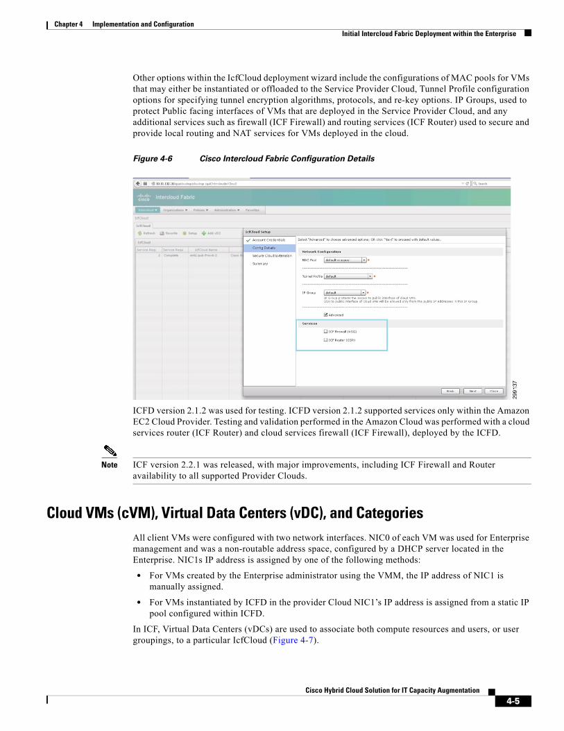
Other options within the IcfCloud deployment wizard include the configurations of MAC pools for VMs that may either be instantiated or offloaded to the Service Provider Cloud, Tunnel Profile configuration options for specifying tunnel encryption algorithms, protocols, and re-key options. IP Groups, used to protect Public facing interfaces of VMs that are deployed in the Service Provider Cloud, and any additional services such as firewall (ICF Firewall) and routing services (ICF Router) used to secure and provide local routing and NAT services for VMs deployed in the cloud.
Figure 4-6 Cisco Intercloud Fabric Configuration Details
ICFD version 2.1.2 was used for testing. ICFD version 2.1.2 supported services only within the Amazon EC2 Cloud Provider. Testing and validation performed in the Amazon Cloud was performed with a cloud services router (ICF Router) and cloud services firewall (ICF Firewall), deployed by the ICFD.
Note ICF version 2.2.1 was released, with major improvements, including ICF Firewall and Router availability to all supported Provider Clouds.
Cloud VMs (cVM), Virtual Data Centers (vDC), and CategoriesAll client VMs were configured with two network interfaces. NIC0 of each VM was used for Enterprise management and was a non-routable address space, configured by a DHCP server located in the Enterprise. NIC1s IP address is assigned by one of the following methods:
• For VMs created by the Enterprise administrator using the VMM, the IP address of NIC1 is manually assigned.
• For VMs instantiated by ICFD in the provider Cloud NIC1’s IP address is assigned from a static IP pool configured within ICFD.
In ICF, Virtual Data Centers (vDCs) are used to associate both compute resources and users, or user groupings, to a particular IcfCloud (Figure 4-7).
4-5Cisco Hybrid Cloud Solution for IT Capacity Augmentation

Chapter 4 Implementation and Configuration Initial Intercloud Fabric Deployment within the Enterprise
Figure 4-7 vDC Overview
There are three policies defined in the vDC:
• Compute Policy—Used only for Private Cloud vDC to identify hypervisor targets for placement during offloading back operations from the provider Cloud to the Enterprise.
• Network Policy—Used for both Private and Public Cloud vDCs, to define the number of network interfaces and port profile (port group/VLAN) assignments, as well as set the IP assignment method (DHCP / Static IP Pool).
• System Policy—Used only for Public Cloud vDC to define the naming policy of instantiated VMs in the provider Cloud and insert the appropriate DNS information.
To give more flexibility within vDCs, this default policy is overwritten by categories that are defined within the vDC. These Categories allow for differing hypervisor host placement, or naming, as well as differing network types that may be required for different applications. In testing, each type of service (Web, Application, Database) that comprised the 3-Tier application was assigned to categories to provide name prefixes appropriate for their application types, and network interfaces on the appropriate overlay extended network tiers. Each type of service was assigned a unique VLAN that had been extended to the Service Provider Cloud. Figure 4-8 shows categories configured in the ICFD for a Private Cloud vDC allowing for differentiated compute and network policies depending on the application.
Figure 4-8 Private Cloud vDC Categories
Figure 4-9 shows categories configured in the ICFD for a Public Cloud vDC allowing for differentiated System (Deployment) and Network policies depending upon the application.
Figure 4-9 Public Cloud vDC Categories
vDC 1 (Group 1)
Compute Policy
Network Policy
vDC 2 (Group 2)
Compute Policy
Network Policy
2991
38
ICX
Enterprise Environment
ICS
SP Environment
vDC 3 (Group 3)
Compute Policy
Network Policy
vDC 1 (Group 1)
Compute Policy
Network Policy
vDC 2 (Group 2)
Compute Policy
Network Policy
vDC 3 (Group 3)
System Policy
Network Policy
ICLINK
4-6Cisco Hybrid Cloud Solution for IT Capacity Augmentation
Chapter 4 Implementation and Configuration Intercloud Fabric Implementation for Cisco Powered Provider
With vDC Categories applied, an instantiated cVM can receive an appropriate name using a prefix like “web-” that would be enumerated by the ICFD Service Request number to ensure its uniqueness.
Network interfaces are configured to static IPs from dedicated pools, or is specified to request a DHCP supplied IP for the interface as the Network Policy dictates.
Finally these Categories can set appropriate Private Cloud target destinations for applications that may have differing requirements, allowing some cVMs to return to higher processor or faster storage clusters.
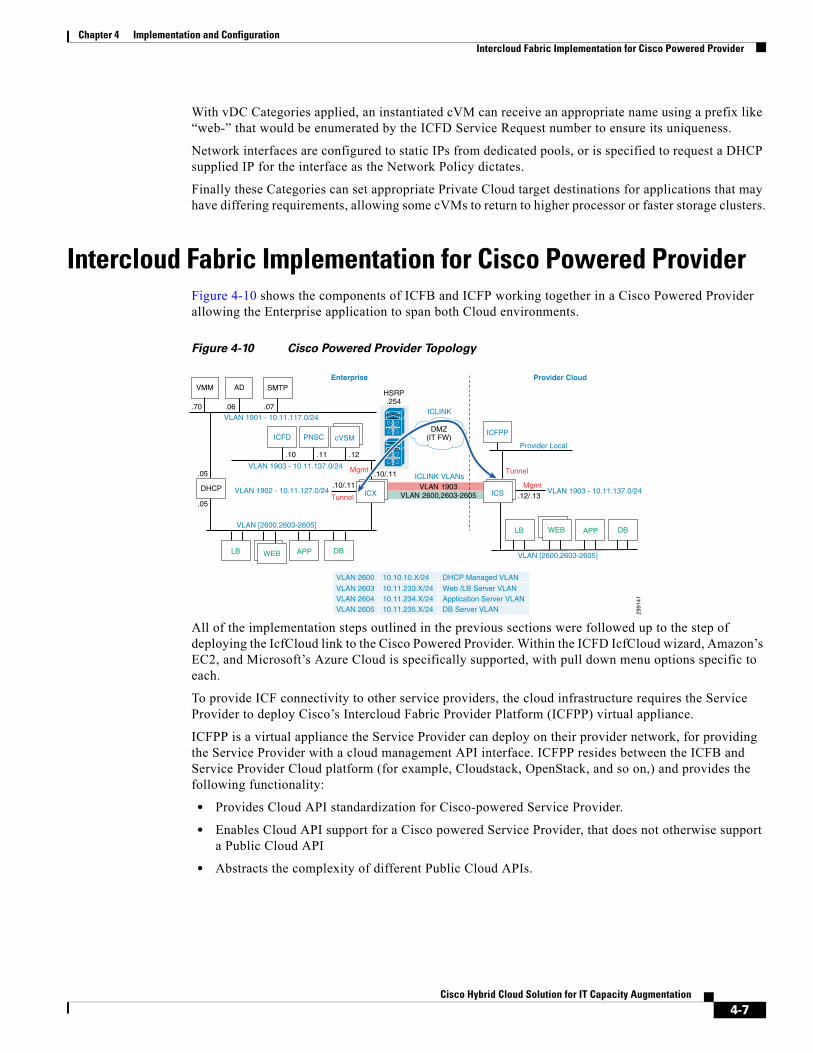
Intercloud Fabric Implementation for Cisco Powered ProviderFigure 4-10 shows the components of ICFB and ICFP working together in a Cisco Powered Provider allowing the Enterprise application to span both Cloud environments.
Figure 4-10 Cisco Powered Provider Topology
All of the implementation steps outlined in the previous sections were followed up to the step of deploying the IcfCloud link to the Cisco Powered Provider. Within the ICFD IcfCloud wizard, Amazon’s EC2, and Microsoft’s Azure Cloud is specifically supported, with pull down menu options specific to each.
To provide ICF connectivity to other service providers, the cloud infrastructure requires the Service Provider to deploy Cisco’s Intercloud Fabric Provider Platform (ICFPP) virtual appliance.
ICFPP is a virtual appliance the Service Provider can deploy on their provider network, for providing the Service Provider with a cloud management API interface. ICFPP resides between the ICFB and Service Provider Cloud platform (for example, Cloudstack, OpenStack, and so on,) and provides the following functionality:
• Provides Cloud API standardization for Cisco-powered Service Provider.
• Enables Cloud API support for a Cisco powered Service Provider, that does not otherwise support a Public Cloud API
• Abstracts the complexity of different Public Cloud APIs.
HSRP.254
2991
41
Mgmt
Mgmt
ADVMM SMTP
VLAN 1901 - 10.11.117.0/24
.10 .11 .12
.06 .07.70
VLAN 2600,2603-2605VLAN 1903
DMZ(IT FW)
Enterprise Provider Cloud
.10/.11
Tunnel
Tunnel
.10/.11
VLAN 1903 - 10.11.137.0/24
VLAN 1903 - 10.11.137.0/24
ICLINK
ICLINK VLANs
VLAN 1902 - 10.11.127.0/24
VLAN [2600,2603-2605]
VLAN [2600,2603-2605]
.12/.13.05
.05
VLAN 2600 10.10.10.X/24 DHCP Managed VLAN
VLAN 2603 10.11.233.X/24 Web /LB Server VLAN VLAN 2604 10.11.234.X/24 Application Server VLAN VLAN 2605 10.11.235.X/24 DB Server VLAN
ICFDICFPP
PNSC cVSM
ICX ICSDHCP
APP
APP
DB
DB
LB
LB
WEB
WEB
Provider Local
4-7Cisco Hybrid Cloud Solution for IT Capacity Augmentation
Chapter 4 Implementation and Configuration Intercloud Fabric Implementation for Amazon
Enterprise customers need credentials established by the Cisco Powered Provider to allow for the use of the “public facing” API Services presented by the ICFPP appliance. Enterprise Administrators then use those credentials to authenticate to the ICFPP appliance, create the Intercloud Switch (ICS) component and the IcfCloud between the Enterprise and the Cisco Powered Provider. For more information on the ICFPP virtual appliance refer to the Cisco Intercloud Fabric Architectural Overview.
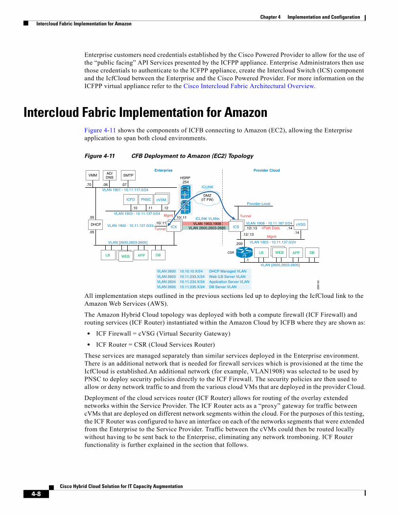
Intercloud Fabric Implementation for AmazonFigure 4-11 shows the components of ICFB connecting to Amazon (EC2), allowing the Enterprise application to span both cloud environments.
Figure 4-11 CFB Deployment to Amazon (EC2) Topology
All implementation steps outlined in the previous sections led up to deploying the IcfCloud link to the Amazon Web Services (AWS).
The Amazon Hybrid Cloud topology was deployed with both a compute firewall (ICF Firewall) and routing services (ICF Router) instantiated within the Amazon Cloud by ICFB where they are shown as:
• ICF Firewall = cVSG (Virtual Security Gateway)
• ICF Router = CSR (Cloud Services Router)
These services are managed separately than similar services deployed in the Enterprise environment. There is an additional network that is needed for firewall services which is provisioned at the time the IcfCloud is established.An additional network (for example, VLAN1908) was selected to be used by PNSC to deploy security policies directly to the ICF Firewall. The security policies are then used to allow or deny network traffic to and from the various cloud VMs that are deployed in the provider Cloud.
Deployment of the cloud services router (ICF Router) allows for routing of the overlay extended networks within the Service Provider. The ICF Router acts as a “proxy” gateway for traffic between cVMs that are deployed on different network segments within the cloud. For the purposes of this testing, the ICF Router was configured to have an interface on each of the networks segments that were extended from the Enterprise to the Service Provider. Traffic between the cVMs could then be routed locally without having to be sent back to the Enterprise, eliminating any network tromboning. ICF Router functionality is further explained in the section that follows.
HSRP.254
2991
42
Mgmt
Mgmt
AD/DNS
VMM SMTP
VLAN 1901 - 10.11.117.0/24
Provider Local.10 .11 .12
.06 .07.70
VLAN 2600,2603-2605VLAN 1903,1908
DMZ(IT FW)
Enterprise Provider Cloud
.10/.11
Tunnel
Tunnel
vPath Data.10/.11
VLAN 1903 - 10.11.137.0/24
VLAN 1908 - 10.11.187.0/24
VLAN 1903 - 10.11.137.0/24
ICLINK
ICLINK VLANs
VLAN 1902 - 10.11.127.0/24
VLAN [2600,2603-2605]
VLAN [2600,2603-2605]
.1
.12/.13
.14.12/.13.14
CSR
.200
.05
.05
VLAN 2600 10.10.10.X/24 DHCP Managed VLAN
VLAN 2603 10.11.233.X/24 Web /LB Server VLAN VLAN 2604 10.11.234.X/24 Application Server VLAN VLAN 2605 10.11.235.X/24 DB Server VLAN
ICFD PNSC cVSM
ICX ICSDHCP cVSG
APPAPP
DBDB
LBLB
WEBWEB
.1
4-8Cisco Hybrid Cloud Solution for IT Capacity Augmentation
Chapter 4 Implementation and Configuration Intercloud Fabric Implementation for Amazon
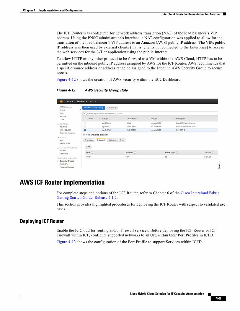
The ICF Router was configured for network address translation (NAT) of the load balancer’s VIP address. Using the PNSC administrator’s interface, a NAT configuration was applied to allow for the translation of the load balancer’s VIP address to an Amazon (AWS) public IP address. The VIPs public IP address was then used by external clients (that is, clients not connected to the Enterprise) to access the web services for the 3-Tier application using the public Internet.
To allow HTTP or any other protocol to be forward to a VM within the AWS Cloud, HTTP has to be permitted on the inbound public IP address assigned by AWS for the ICF Router. AWS recommends that a specific source address or address range be assigned to the Inbound AWS Security Group to secure access.
Figure 4-12 shows the creation of AWS security within the EC2 Dashboard
Figure 4-12 AWS Security Group Rule
AWS ICF Router ImplementationFor complete steps and options of the ICF Router, refer to Chapter 6 of the Cisco Intercloud Fabric Getting Started Guide, Release 2.1.2.
This section provides highlighted procedures for deploying the ICF Router with respect to validated use cases.
Deploying ICF Router
Enable the IcfCloud for routing and/or firewall services. Before deploying the ICF Router or ICF Firewall within ICF, configure supported networks to an Org within their Port Profiles in ICFD.
Figure 4-13 shows the configuration of the Port Profile to support Services within ICFD.
4-9Cisco Hybrid Cloud Solution for IT Capacity Augmentation

Chapter 4 Implementation and Configuration Intercloud Fabric Implementation for Amazon
Figure 4-13 Configure Services and Org in Port Profile
An Org is specified or created from editing a Port Profile, or during the creation of a Port Profile. With an Org in place, it appears in PNSC under Resource Management > Managed Resources an ICF Router is added from here using the Actions pull-down menu selecting the Add Edge Router option as shown in Figure 4-14.
Figure 4-14 Adding the ICF Router from the Org “ent4” Shown in PNSC
The following five types of interfaces are available when deploying an ICF Router:
1. Gigabit Ethernet—Data interfaces for inter-VLAN routing, with a minimum of two interfaces.
2. Tunnel—Used for creating an IPSec tunnel.
3. Loopback—Termination point for routing protocols established on the ICF Router.
4. Management—Required interface, using two IPs, one for management access and another dedicated to PNSC communication.
5. Public Cloud—Optional interface to allow external access to cVMs as well as externally accessible NATs.
The validation focused on using the interfaces shown in Figure 4-15.
4-10Cisco Hybrid Cloud Solution for IT Capacity Augmentation

Chapter 4 Implementation and Configuration Intercloud Fabric Implementation for Amazon
Figure 4-15 ICF Router Interfaces Configured During Deployment
This allowed for management of the ICF Router, inter-VLAN routing, Internet access for cVMs, and the eventual configuration of a static NAT. Static NAT was used to present the 3-Tier application to be externally accessible from the Public Interface.
The Management interface needs L2 or L3 reachability back to PNSC and ICS. If a Public Interface is added, configure the Management interface route to reach the Enterprise networks that are not configured on an interface of the ICF Router. The route is inserted within the Device Service Profile of the ICF Router.
The Device Service Profile is created within PNSC at Policy Management > Service Profiles > (Org ICF Router is deployed to) > Edge Router > Device Service Profiles. The Routing Policy shown in Figure 4-16 is the first listed section under Policies, with the second option handling the NAT configuration touched on later in this section.
4-11Cisco Hybrid Cloud Solution for IT Capacity Augmentation

Chapter 4 Implementation and Configuration Intercloud Fabric Implementation for Amazon
Figure 4-16 ICF Router Device Service Profile Configuration
Enabling Inter-VLAN Routing
IcfCloud extended networks is optimized for use with Gigabit Ethernet interfaces set up to extend the default gateway of the Enterprise. The extended gateway enables inter-VLAN routing without requiring any change on the cVMs located in the provider Cloud. This extension of the gateway inserts an ARP filter in the ICS to redirect any requests to the Enterprise gateway to the ICF Router.
Figure 4-17 Inter-VLAN Routing Enabled with ARP Filtering
With the ARP filtering in place (Figure 4-17), cVMs is directed to the ICF Router automatically, without unnecessary packet tromboning.
The Public Interface of the ICF Router automatically creates a NAT Overload configuration to allow external Internet access for cVMs without tunneling back to the Enterprise. This same Public Interface was also used in the use cases to provide static NAT to the LB cVM to present the 3-Tier App for external web consumption.
2991
48
EnterpriseEnvironment
Intercloud Switch
CSR
VLAN 1703 SVIIP 10.11.135.254
VLAN 2303 SVIIP 10.11.213.254MAC 0000.0c9f.f8ff
VLAN 2304 SVIIP 10.11.214.254MAC 0000.0c9f.f900
VLAN 2305 SVIIP 10.11.215.254MAC 0000.0c9f.f901
Mgmt [VLAN 1703]Mgmt IP 10.11.135.1Service IP 10.11.135.2
Public [Provider Local]
Tier1 [VLAN 2303]IP 10.11.213.1MAC 000e.0800.0012
Tier2 [VLAN 2304]IP 10.11.214.1MAC 000e.0800.0012
Tier3 [VLAN 2305]IP 10.11.215.1MAC 000e.0800.0012
arp table (vemcmd show arp all)
VLAN230323042305
IP10.11.213.254 10.11.214.254 10.11.215.254
MAC000e.0800.0012000e.0800.0012 000e.0800.0012
4-12Cisco Hybrid Cloud Solution for IT Capacity Augmentation

Chapter 4 Implementation and Configuration Intercloud Fabric Implementation for Amazon
Extended Routing and NAT Configuration
The Routing Policy (Figure 4-18) allows for communication of cVMs that need to reach Enterprise infrastructure resources on the example 10.11.115.0/24 network. Any additional, non-ICF extended segments would need to be added in this way, or through one of the advanced routing options of BGP, OSPF, or EIGRP within the Routing Policy. This is not completely necessary in the most basic deployment of ICF Router, but with the addition of a Public interface, the default route is switched from an Enterprise router to the provider side gateway.
Figure 4-18 ICF Router Interfaces with Device Service Profile Applied
Static NATs were configured for the web front end servers to verify external reachability. This required a NAT policy pointing to an inside NAT address of the LB resource, and a corresponding outside NAT address of the AWS provider side private IP it was mapped to. These 172.x.x.x addresses shown in Figure 4-18 for the primary IP and secondary IP of the Public interface are mapped to public facing IPs that are handled by AWS.
The Static NAT is assigned to the ICF Router within the AWS EC2 Dashboard.
Note AWS Login and password required to access AWS EC2 Dashboard
From the AWS EC2 Dashboard, find the ICF Router from within the Instances and right click to select Networking > Manage Private IP Address within the pull down. From the Manage Private IP Address wizard click Assign new IP, and click Yes, Update to add the IP.
In Figure 4-19 the secondary private IP assigned is 172.31.21.172, with the original private IP shown as 172.31.27.52. The primary private IP has a public IP associated with it, but this is not a persistent assignment. To maintain the same public IP between reboots, this secondary IP is associated with an Elastic IP within AWS.
Service Profileinside-nat
2991
49
CSR
Mgmt [VLAN 1703]Mgmt IP 10.11.135.1Service IP 10.11.135.2
Public [Provider Local]Primary IP 172.31.25.206Secondary IP172.31.16.38
Service Profileoutside-nat
Tier1 [VLAN 2303]IP 10.11.213.1MAC 000e.0800.0012
Tier2 [VLAN 2304]IP 10.11.214.1MAC 000e.0800.0012
Tier3 [VLAN 2305]IP 10.11.215.1MAC 000e.0800.0012
Device Service Profile - Policies
Routing PolicyStatic10.11.115.0/24 -> 10.11.135.254
NAT Policyinside-nat 10.11.213.125 <->outside-nat172.31.16.38
4-13Cisco Hybrid Cloud Solution for IT Capacity Augmentation

Chapter 4 Implementation and Configuration Intercloud Fabric Implementation for Amazon
Figure 4-19 AWS Manage Private IP address
To acquire an Elastic IP, select Elastic IPs from within the Networking & Security section of the AWS EC2 Dashboard, and click the Allocate New Address button which results in the addition of 52.5.176.220 in Figure 4-20.
Figure 4-20 Elastic IP Assignments
Select this new Elastic IP and click the Associate Address button shown in Figure 4-20, type in the name of the ICF Router to associate it to, which automatically translates to the instance ID once selected. Leave the pull-down of the Private IP Address to the primary private IP shown as 172.31.27.52 here, and click Associate in Figure 4-21 to finish:
4-14Cisco Hybrid Cloud Solution for IT Capacity Augmentation

Chapter 4 Implementation and Configuration Intercloud Fabric Implementation for Amazon
Figure 4-21 Elastic IP Association
With the elastic IP associated, the original public IP is gone, and the new Public DNS and Public IP both map into the value for the Elastic IP:
Figure 4-22 Elastic IP is Now the Same as the Public IP
With the AWS Elastic IP setup completed, as shown in Figure 4-22, an additional Network Security Group needs to be added to the CSR instance before the AWS EC2 Console is finished. To add a new Network Security Group, select the Create Security Group option from within NETWORK & Security > Security Groups of the EC2 Dashboard opening up dialogue box shown in Figure 4-23.
4-15Cisco Hybrid Cloud Solution for IT Capacity Augmentation

Chapter 4 Implementation and Configuration Intercloud Fabric Implementation for Amazon
Figure 4-23 Create Security Group from EC2 Dashboard
This allows predefined or custom options, for traffic types, as well as sources and destinations.
With a Network Security Group created to allow the specific traffic of the application, select the instance of the CSR within the EC2 Dashboard under INSTANCES > Instances, and right click the instance or use the Actions pull down to select Networking > Change Security Groups. From within the Change Security dialog box, select the entry for the new Network Security Group, and click the Assign Security Groups to apply the change.
With the AWS configuration complete, configure the NAT Policy components within PNSC by creating the appropriate Device Service Profile and Interface Service Profiles.
Figure 4-24 Device Service Profile and Interface Service Profiles
The Device Service Profile establishes the rules used for the NAT translation as it is applied to interfaces within the Interface Service Profiles. The Device Service Profile is set in the first screen of the ICF Router configuration wizard under Resource Management > Managed Resources > {Org} > Edit selecting the deployed ICF Router instance as shown in Figure 4-25.
2991
55
Device Service Profile - Policies Interface Service Profile
NAT Policy Set {enabled|disabled}
Bold represents selected options
NAT Policy {enabled|disabled}
NAT Rule{Match Conditions: Source <-> DestinationProtocol: Any|SpecificNAT Action: Static|DynamicTranslated Address: Source, DestinationNAT Options: Enable Bidirectional, Enable DNS, Disable Proxy ARP}
Public
Tier1
Service Profileoutside-nat
{Enable NAT;inside|outside}
Service Profileinside-nat
{Enable NAT;inside|outside}
4-16Cisco Hybrid Cloud Solution for IT Capacity Augmentation

Chapter 4 Implementation and Configuration Intercloud Fabric Implementation for Amazon
Figure 4-25 Device Service Profile for the ICF Router
Configuration of the Device Service Profile and subcomponent NAT policies and objects is found in PNSC at:
• Device Service Profile—QPolicy Management > Service Profiles > {Org} > Edge Router > Device Service Profiles
• NAT Policy Set—Policy Management > Service Policies > {Org} > Policies> NAT > NAT Policy Sets
• NAT Policy—Policy Management > Service Policies > {Org} > Policies > NAT > NAT Policies
• Object Group—Policy Management > Service Policies > {Org} > Policy Helpers > Object Groups
This last component listed, called Object Group is not seen in Figure 4-24, but is used as the Source object in the NAT Rule for the Match Condition of the translation.
With the NAT established through the Device Service Profile, it is enabled by applying Interface Service Profiles representing the inside and outside of the translation that occurs. These are applied within the Network Interfaces tab of Resource Management > Managed Resources > {Org} > Edit of the deployed ICF Router instance, as shown in Figure 4-26.
4-17Cisco Hybrid Cloud Solution for IT Capacity Augmentation

Chapter 4 Implementation and Configuration Intercloud Fabric Implementation for Amazon
Figure 4-26 Assign Interface Service Profiles to the Interfaces
These Service Profiles (Interface Service Profiles) are created in PNSC within: Policy Management > Service Profiles > {Org} > Edge Router > Interface Service Profiles
Within the Interface Service Profile, the specification of “Enable NAT”, and if the NAT interface type is Inside or Outside are a minimum requirement. Settings for DHCP Relay, VPN Interface, and ACLs for ingress or egress can additionally be applied.
ICF Firewall Implementation into AWSA compute firewall (ICF Firewall) VM is deployed into the AWS Cloud to restrict access specifically to the Virtual IP address (VIP) of the load balancer. However, depending upon the application that is deployed (for example Microsoft SharePoint) other protocol access is needed specifically for DNS and Active Directory traffic to allow SharePoint to function properly.
The following is the list of tasks that need to be completed to deploy the ICF Firewall into AWS:
• Create ICF Firewall Data Interface Port-Profile
• Create ICF Firewall Data Interface IP Pool
• Add ICF Firewall Service to the IcfCloud
• Configure PNSC for ICF Firewall Service
– Add ICF Firewall Resource
– Add (Optional) vZone(s) for Web Front End Servers
– Create Security Profile
– Add ICF Firewall to the Service Path
– Associate ICF Firewall Service Path to cVSM Port-Profile
Create ICF Firewall Data Interface Port-Profile
Create a dedicated Port Profile for the Firewall Data interface, as shown in Figure 4-27, on the cVSM using the ICFD GUI manager by selecting Intercloud > All Clouds > IcfVSM > Add Port Profile
4-18Cisco Hybrid Cloud Solution for IT Capacity Augmentation
Chapter 4 Implementation and Configuration Intercloud Fabric Implementation for Amazon
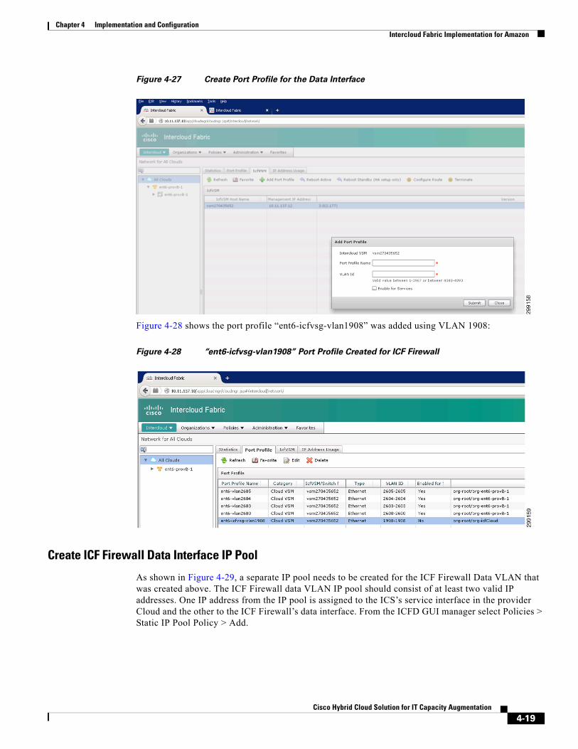
Figure 4-27 Create Port Profile for the Data Interface
Figure 4-28 shows the port profile “ent6-icfvsg-vlan1908” was added using VLAN 1908:
Figure 4-28 “ent6-icfvsg-vlan1908” Port Profile Created for ICF Firewall
Create ICF Firewall Data Interface IP Pool
As shown in Figure 4-29, a separate IP pool needs to be created for the ICF Firewall Data VLAN that was created above. The ICF Firewall data VLAN IP pool should consist of at least two valid IP addresses. One IP address from the IP pool is assigned to the ICS’s service interface in the provider Cloud and the other to the ICF Firewall’s data interface. From the ICFD GUI manager select Policies > Static IP Pool Policy > Add.
4-19Cisco Hybrid Cloud Solution for IT Capacity Augmentation

Chapter 4 Implementation and Configuration Intercloud Fabric Implementation for Amazon
Figure 4-29 Static IP Pool Created for the ICF Firewall
Add ICF Firewall Services to the IcfCloud
To add ICF Firewall Services to the IcfCloud, from the ICFD Gui Manager, select Intercloud > highlight the cloud you want to add services too > select Add Services. After selecting Add Services, a pop up menu appears to allow you to select ICF Firewall and/or ICF Router.
As shown in Figure 4-30, after selecting the ICF Firewall (VSG) check box, enter the Service Interface VLAN (for example, VLAN1908), as well as the Service Interface IP Policy, created above (for example, ent6-icfvsg-vlan1908). The remaining portions of the ICF Firewall configuration are performed through the PNSC web console in the next section.
Figure 4-30 Add ICF Firewall to the Provider Cloud
4-20Cisco Hybrid Cloud Solution for IT Capacity Augmentation

Chapter 4 Implementation and Configuration Intercloud Fabric Implementation for Amazon
Using PNSC to Configure and Deploy the ICF Firewall ServiceFrom the PNSC GUI Manager, create the ICF Firewall by selecting Resource Management > Managed Resources > {org} (ent6-provB-1) > Highlight Network Services in the right pane and using the Actions pull down menu Select “+ Add Compute Firewall”.
Figure 4-31 Add Compute Firewall using the PNSC GUI Manager
After selecting “+ Add Compute Firewall” a configuration wizard is invoked to deploy the ICF Firewall into the provider Cloud.
Figure 4-32 CF Firewall Properties
4-21Cisco Hybrid Cloud Solution for IT Capacity Augmentation

Chapter 4 Implementation and Configuration Intercloud Fabric Implementation for Amazon
In Figure 4-32, specify the name and host name of the ICF Firewall. A specific device profile for the ICF Firewall may be used to configure specific administrative policies or settings, such as NTP, DNS or syslog server. The Device Profile is configured and applied to the ICF Firewall after it has been deployed.
Figure 4-33 Instantiate ICF Firewall in the Cloud
Figure 4-33 select “Instantiate in Cloud” to deploy the ICF Firewall in the provider Cloud. If previous versions of the ICF Firewall image are available, select the appropriate version.
4-22Cisco Hybrid Cloud Solution for IT Capacity Augmentation

Chapter 4 Implementation and Configuration Intercloud Fabric Implementation for Amazon
Figure 4-34 Select the Appropriate IcfCloud for Placement of the ICF Firewall
If there was multiple IcfClouds configured, as shown in Figure 4-34 the ICF Firewall is placed in to a specific IcfCloud. In this example, there is only a single IcfCloud currently configured.
4-23Cisco Hybrid Cloud Solution for IT Capacity Augmentation

Chapter 4 Implementation and Configuration Intercloud Fabric Implementation for Amazon
Figure 4-35 Configure Management Interface
As shown in Figure 4-35 and Figure 4-36, 2 ICF Firewall interfaces need to be configured. One Management and one Data interface. The configurations are performed separately through the wizard. Make sure to select the correct Port Group for each type of interface.
4-24Cisco Hybrid Cloud Solution for IT Capacity Augmentation

Chapter 4 Implementation and Configuration Intercloud Fabric Implementation for Amazon
Figure 4-36 Configure Data Interface
Lastly, review and finalize the ICF Firewall configuration, as shown in Figure 4-37.
4-25Cisco Hybrid Cloud Solution for IT Capacity Augmentation

Chapter 4 Implementation and Configuration Intercloud Fabric Implementation for Amazon
Figure 4-37 ICF Firewall Deployment Summary
Add (Optional) vZone(s)
Source and destination objects is configured as one of four types of attributes: network, VM, user defined and vZones.
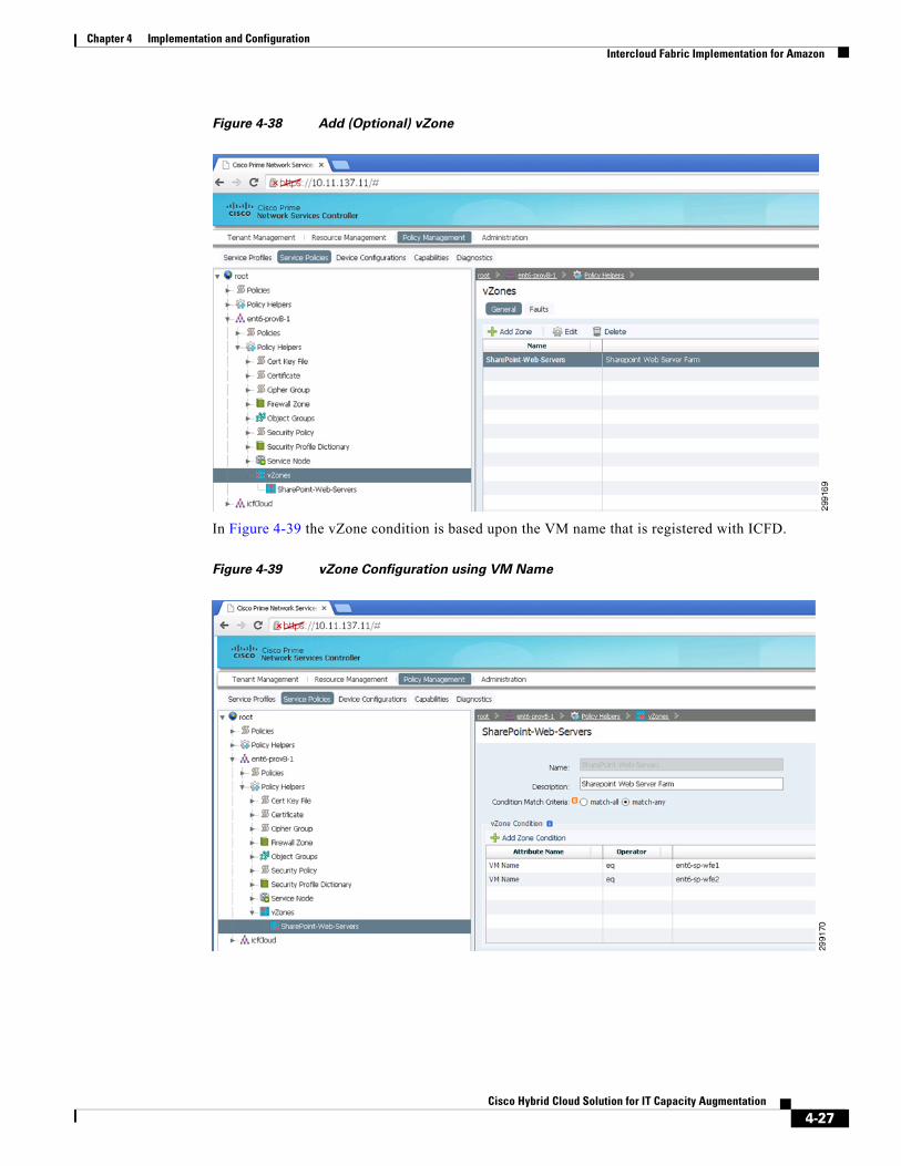
Shown in Figure 4-38 both of the Microsoft SharePoint Web Front End Servers are added to a vZone named “SharePoint-Web-Server”. Creating a vZone allows the administrator to group virtual machines together, and apply specific firewall rules to all devices within that vZone.
4-26Cisco Hybrid Cloud Solution for IT Capacity Augmentation
Chapter 4 Implementation and Configuration Intercloud Fabric Implementation for Amazon
Figure 4-38 Add (Optional) vZone
In Figure 4-39 the vZone condition is based upon the VM name that is registered with ICFD.
Figure 4-39 vZone Configuration using VM Name
4-27Cisco Hybrid Cloud Solution for IT Capacity Augmentation
Chapter 4 Implementation and Configuration Intercloud Fabric Implementation for Amazon
Create Security Profile(s)
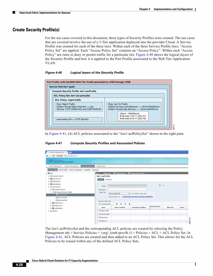
For the use cases covered in this document, three types of Security Profiles were created. The use cases that are covered involve the use of a 3-Tier application deployed into the provider Cloud. A Service Profile was created for each of the three tiers. Within each of the three Service Profile tiers, “Access Policy Set” are applied. Each “Access Policy Set” contains an “Access Policy”. Within each “Access Policy” are rules to deny or permit traffic for a particular tier. Figure 4-40 shows the logical layers of the Security Profile and how it is applied to the Port Profile associated to the Web Tier Application VLAN.
Figure 4-40 Logical layers of the Security Profile
In Figure 4-41, (4) ACL policies associated to the “tier1-aclPolicySet” shown in the right pane.
Figure 4-41 Compute Security Profiles and Associated Policies
The tier1-aclPolicySet and the corresponding ACL policies are created by selecting the Policy Management tab > Service Policies > {org} (ent6-provB-1) > Policies > ACL > ACL Policy Set. In Figure 4-41, ACL Policies are created and then added to an ACL Policy Set. This allows for the ACL Policies to be reused within any of the defined ACL Policy Sets.
Service Path:tier1-spath
Port Profile: ent6-vlan2603 (Web Tier VLAN) associated to cVSG through cVSM
Compute Security Profile: tier1-secProfile
ACL Policy Set: tier1-acl-policySet
2991
71
ACL Policy: mgmt-traffic
vZone – WebServerEnt6-web-1/10.11.233.101Ent6-web-2/10.11.233.102
Rule: tier1-lb-Traffic[Object Group] Load-Balancer –> vZone-WebServer[Object Group] App Servers –> vZone-WebServer
Rule: Mgmt-Traffic[Object Group] Mgmt-Subnets –> anyService: (TCP 22/80/443) and ICMP/DNS/AD
externalAny-IP<-> (TCP 80/443)
4-28Cisco Hybrid Cloud Solution for IT Capacity Augmentation

Chapter 4 Implementation and Configuration Intercloud Fabric Implementation for Amazon
Figure 4-42 Add, Remove, or Reorder ACL Policies per ACL Policy Sets
As shown in Figure 4-43, various ACL rules is organized into ACL polices and then grouped into an ACL Policy set. Structuring the ACL policies to manage a particular traffic type allows the ACL policy to be re-used in other ACL Policy Sets.
Figure 4-43 Organize ACL Polices and Associated Rules in a Logical Manner
As shown in Figure 4-43, various ACL rules are grouped together to manage a specific network traffic types.
Create Firewall Service Paths
After the creation of a Compute Security Profile, it is specified in the Service Path as the Service Profile, along with the service node of the ICF Firewall (Figure 4-44).
4-29Cisco Hybrid Cloud Solution for IT Capacity Augmentation

Chapter 4 Implementation and Configuration Intercloud Fabric Implementation for Amazon
Figure 4-44 Associate Service Profile to a Service Path
Associate Service Paths to Port Profiles
As shown in Figure 4-45, apply Service Path to the port profile. Resource Management > Managed Resources > {org}(ent6-provB-1) > Port Profiles.
4-30Cisco Hybrid Cloud Solution for IT Capacity Augmentation

Chapter 4 Implementation and Configuration Intercloud Fabric Implementation for Amazon
Figure 4-45 Select the Service Path
Select the port profile, in this example ent6-vlan2603 is the Microsoft SharePoint Web service network, and right click to edit the port profile. In Figure 4-45, select the appropriate Service Path profile to be applied. In the same screen, to disassociate the port-profile from the firewall, check the “Disassociate” box.
In Figure 4-46, verify that the appropriate Security Profiles are applied to the correct Port Profiles on the cVSM.
4-31Cisco Hybrid Cloud Solution for IT Capacity Augmentation

Chapter 4 Implementation and Configuration Intercloud Fabric Implementation for Amazon
Figure 4-46 Verify Security Profile is Applied to the Correct Port Profile
As shown in Figure 4-47, the port profiles are now associated to the Service Path.
Figure 4-47 Verify Port Profiles and Service Path
ICF Firewall Rule Verification with a Syslog ServerA syslog server was deployed into the Enterprise, and logging was enabled on specific firewall rule sets to determine the network traffic to be allowed or denied. Monitoring of the syslog messages helped to identify required traffic that the application needed to function properly.
A CentOS 6.3 Syslog Server was deployed into the ICF management network within the Enterprise environment to monitor the log messages being generated by the firewall rule sets. Information for configuring a generic syslog server is found on the Internet
4-32Cisco Hybrid Cloud Solution for IT Capacity Augmentation

Chapter 4 Implementation and Configuration Intercloud Fabric Implementation for Amazon
Centos Syslog Server Configuraton (rsyslog.conf)
# Provides UDP syslog reception$ModLoad imudp$UDPServerRun 514
# Provides TCP syslog reception$ModLoad imtcp$InputTCPServerRun 514
#### RULES ####
# Log anything (except mail) of level info or higher.# Don't log private authentication messages!*.info;mail.none;authpriv.none;cron.none local6.* /var/log/messages
Configuring an ICF Firewall
Perform the following procedures to configure an ICF Firewall to send log messages to a syslog server.
Step 1 Create Syslog Policy.
Step 2 Create Device Profile.
Step 3 Add the Syslog Policy into the Device Profile.
Step 4 Apply the Device Profile to the ICF Firewall.
Step 5 Create the Syslog Policy from Administration > System Profile > Policies > Syslog > Add Syslog Policy. From the servers tab within the created syslog policy, select add Syslog Server.
Figure 4-48 Forwarding Facility Should Match Syslog Configuration
The forwarding facility shown in Figure 4-48 (for example, local6) should match what was configured in the syslog.conf file on syslog server.
Step 6 Policy Management >Device Configurations > {org} (ent6-provB-1) >Device Profile > Add Device Profile and select the syslog policy just created to the Syslog section, along with any appropriate DNS and NTP information (Figure 4-49).
4-33Cisco Hybrid Cloud Solution for IT Capacity Augmentation

Chapter 4 Implementation and Configuration Intercloud Fabric Implementation for Amazon
Figure 4-49 Apply the specific Syslog Policy in the Device Profile
Step 7 Apply the device profile to the ICF Firewall: Resource Management > {org} (ent6-provB-1) > select ICF Firewall(ent6-ICF Firewall) > General tab and in the Device Profile field select the syslog device profile (Figure 4-50).
Figure 4-50 Apply Syslog Device Profile to the ICF Firewall
4-34Cisco Hybrid Cloud Solution for IT Capacity Augmentation

Chapter 4 Implementation and Configuration Intercloud Fabric Implementation
Intercloud Fabric ImplementationIntercloud Fabric implementation guidance is provided for the following:
• Intercloud Fabric Implementation for Azure, page 4-35
• Intercloud Fabric Implementation for Use Case 1, 3-Tier Offloading, page 4-36
• Intercloud Fabric Implementation for Use Case 2, Distributed Work Load, page 4-37
• Intercloud Fabric Implementation for Use Case 3, Planned Peak Capacity, page 4-38
Intercloud Fabric Implementation for AzureAll of the implementation procedures outlined in the previous sections lead to deploying the IcfCloud link to Microsoft Azure.
As noted in the Figure 4-51, services are not supported in this release of ICF. All routing and firewall services were performed by the Enterprise Data Center. All network gateways for cVMs deployed in Microsoft’s Azure Cloud were configured to use the Enterprise’s aggregation routers.
Figure 4-51 Microsoft Azure Topology
In Figure 4-52 the Microsoft Azure connection is specifically supported and was selected from the IcfCloud wizard.
HSRP.254
2991
82
Mgmt
Mgmt
ADVMM SMTP
VLAN 1901 - 10.11.117.0/24
Provider Local.10 .11 .12
.06 .07.70
VLAN 2600,2603-2605VLAN 1903
DMZ(IT FW)
Enterprise Provider Cloud
.10/.11
Tunnel
Tunnel
.10/.11
VLAN 1903 - 10.11.137.0/24
VLAN 1903 - 10.11.137.0/24
ICLINK
ICLINK VLANs
VLAN 1902 - 10.11.127.0/24
VLAN [2600,2603-2605]
VLAN [2600,2603-2605]
.12/.13.05
.05
VLAN 2600 10.10.10.X/24 DHCP Managed VLAN
VLAN 2603 10.11.233.X/24 Web /LB Server VLAN VLAN 2604 10.11.234.X/24 Application Server VLAN VLAN 2605 10.11.235.X/24 DB Server VLAN
ICFD PNSC cVSM
ICXICS
DHCP
APP
APP
DB
DB
LB
LB
WEB
WEB
4-35Cisco Hybrid Cloud Solution for IT Capacity Augmentation

Chapter 4 Implementation and Configuration Intercloud Fabric Implementation
Figure 4-52 Select Cloud Type
Intercloud Fabric Implementation for Use Case 1, 3-Tier OffloadingUse case 1 involved a 3-Tier application consisting of mixed Windows and Linux VM resources (Figure 4-53). The 3-Tier application was comprised of the following VMs and operating systems (Table 4-1).
Table 4-1 Use Case 1, 3-Tier Application VM’s and Operating Systems
Name Application OS Disk vCPU RAM Quantity
Load Balancer (LB) HAProxy RedHat 6.3 16GB 1 4GB 1
Web Front End (WFE) IIS Windows 2008 R2 16GB 1 4GB 2
Application (App) Apache/PHP RedHat 6.3 12GB 1 2GB 1
Backend (DB) MySQL CentOS 6.3 12GB 1 2GB 11
1.Azure testing
Backend (DB) MySQL RedHat 6.3 12GB 1 2GB 12
2.Cisco Powered Provider testing
4-36Cisco Hybrid Cloud Solution for IT Capacity Augmentation

Chapter 4 Implementation and Configuration Intercloud Fabric Implementation
Figure 4-53 3-Tier Offloading
Note OOB interfaces on VLAN 2600 not shown to simplify the Figure 4-53.
As shown in Figure 4-54, VM offloaded can remain in the enterprise and left in a powered off state, or once the VMs have been offloaded, the user or admin has the option to remove them completely.In this example all components of the 3-Tier application and the LB were offloaded to the Provider Cloud.
Intercloud Fabric Implementation for Use Case 2, Distributed Work LoadUse case 2 brought in Microsoft SharePoint as the application used, which like the previous use case was implemented as a 3-Tier application and was presented by a load balancer instance. The SharePoint components were set up as shown in Table 4-2.
Note This setup is below the recommended resource requirements from Microsoft for a SharePoint installation, but was sufficient to show basic functionality of a SharePoint placement.
In the Distributed Work Load use case, the SharePoint resources were first installed in the vSphere Private Cloud and set up with HAProxy as a load balancer in front of the WFE components. After functionality was confirmed, the WFEs and load balancer were offloaded to the IcfCloud extended provider Cloud.
As shown in Figure 4-54, VM offloaded can remain in the enterprise and left in a powered off state, or once the VMs have been offloaded, the user or admin has the option to remove them completely. In this example only the WFEs and LB were offloaded to the Provider Cloud.
2991
84
VLAN 2605
VLAN 2600,2603-2605VLAN 1903
DMZ(IT FW)
Enterprise Provider Cloud
ICLINK
ICLINK VLANs
ICX
DB
VLAN 2604
APP
VLAN 2603
WFELB WFE
VLAN 2605
DB
VLAN 2604
APP
VLAN 2603
WFELB WFE
ICS
Table 4-2 Use Case 2, 3-Tier Application Components
Name Application OS Disk vCPU RAM Quantity
Load Balancer (LB) HAProxy RedHat 6.3 16GB 1 4GB 1
Web Front End (WFE) SharePoint2013 w/IIS Windows 2008 R2 30GB 1 4GB 2
Application (App) SharePoint2013 Windows 2008 R2 60GB 1 4GB 1
Backend (DB) Clustered SQL Server 2008 Windows 2008 R2 80GB 1 4GB 2
4-37Cisco Hybrid Cloud Solution for IT Capacity Augmentation

Chapter 4 Implementation and Configuration Intercloud Fabric Implementation
Basic connectivity was confirmed for each WFE resource that had been offloaded, at this point it was noted that in each provider environment, the ping response time was between 8-10ms. This kind of latency is out of bound for what is supported between tiers in SharePoint, but basic functionality was still observed.
Figure 4-54 Distributed Workload
Note OOB interfaces on VLAN 2600 are not shown to simplify Figure 4-54.
Intercloud Fabric Implementation for Use Case 3, Planned Peak CapacityUse case 3 had the same initial SharePoint 2013 resources as Use Case 2 (Table 4-3).
This use case stays similar to the Distributed Work Load in Use Case2, but in the Planned Peak Capacity situation, the initial WFE have stayed in the Enterprise and two additional WFE components have been instantiated in the Provider Cloud as shown in Figure 4-55.
Figure 4-55 Planned Peak Capacity
2991
85
VLAN 2605
VLAN 2600,2603-2605VLAN 1903
DMZ(IT FW)
Enterprise Provider Cloud
ICLINK
ICLINK VLANs
ICX
DB
VLAN 2604
APP
VLAN 2603
WFELB WFE
VLAN 2605
VLAN 2604
VLAN 2603
WFELB WFE
ICS
Table 4-3 Use Case 3, SharePoint 2013 Resources
Name Application OS Disk vCPU RAM Quantity
Load Balancer (LB) HAProxy RedHat 6.3 16GB 1 4GB 1
Web Front End (WFE) SharePoint2013 w/IIS Windows 2008 R2 30GB 1 4GB 2
Application (App) SharePoint2013 Windows 2008 R2 60GB 1 4GB 1
Backend (DB) Clustered SQL Server 2008 Windows 2008 R2 80GB 1 4GB 2
2991
86
VLAN 2605
VLAN 2600,2603-2605VLAN 1903
DMZ(IT FW)
Enterprise Provider Cloud
ICLINK
ICLINK VLANs
ICX
DB
VLAN 2604
APP
VLAN 2603
WFELB WFE
VLAN 2605
VLAN 2604
VLAN 2603
WFE WFE
ICS
4-38Cisco Hybrid Cloud Solution for IT Capacity Augmentation

Chapter 4 Implementation and Configuration Use Case Testing and Results
Note OOB interfaces on VLAN 2600 not shown to simplify Figure 4-55.
These additional WFE elements are added to the configuration of the LB resource that is still in the Enterprise, and connectivity is tested to confirm that all WFEs are accessible.
Use Case Testing and ResultsThe use case testing had mixed results. All Workload Offloading and instantiations of application components under test worked, and were able to communicate back to the Enterprise environment. Application performance in some cases met expectations, but others were below acceptable levels as explained.
The WAMP 3-Tier worked well and the NAT access from external queries to the load balancer worked with services.
SharePoint had compromised performance as a distributed application between cloud environments. The latency between clouds was significantly beyond the requirements by Microsoft and is assumed to be the source of performance issues. Latency expectation between tiers is expected to be < 1ms, but during testing with displaced tiers, the latency was roughly between 8-12ms as shown in Table 4-4.
Note For distributed applications where different layers are deployed in dispersed clouds (for example, Private and Public Clouds), to meet latency requirements, a dedicated link might be required as opposed to using the Internet to extend the network through Intercloud Fabric. Although not tested as part of this document, ICF abstracts the underlying network and its dependencies, which allows customers to connect to their Cloud provider using different mechanisms, such as: AWS Direct Connect, Azure Express Route or MPLS network connected to Cisco Powered Provider. These solutions might be an alternative to resolve the latency requirement.
The resource requirements used for deployed SharePoint components were also short on expected processor and memory allocations, but these resources were sufficient for basic functionality prior to the offloading testing, so latency is still seen as the primary problem.
After offloading VMs to the Service Provider, the HAProxy was still load balancing either the 3-Tier Application or the SharePoint web front end servers was functioning properly.
Table 4-4 Data from 100 Ping Sequences over IcfCloud
Ping (bytes)Enterprise-AWS (milliseconds)
Enterprise-Azure (milliseconds)
Enterprise-DiData (milliseconds)
Intra-Enterprise (milliseconds)
64k low 10.3 9.34 8.1 0.249
64k high 12.5 13.2 8.77 0.367
64k Avg 10.618 9.8783 8.2833 0.31085
2000k low 11 9.93 8.7 0.318
2000k high 18.4 12.6 9.47 0.52
2000k Avg 11.491 10.5983 8.8932 0.39177
4-39Cisco Hybrid Cloud Solution for IT Capacity Augmentation

Chapter 4 Implementation and Configuration Use Case Testing and Results
3-Tier Offloading to AzureThe 3-Tier application and Load Balancer was instantiated in the Enterprise Data Center, using the VMware vSphere client. The 3-Tier application was comprised of two Windows Servers for the Web Front End Services, one Red Hat Linux VM for the application server, and one Red Hat Linux VM for the database server. HAProxy was used as the Load Balancer running on a CentOS VM. All network connectivity and Load Balancer configurations were verified in the Enterprise Data Center before offloading to the Azure Cloud.
Once the 3-Tier application was verified in the Enterprise Data Center, all VMs were then offloaded to the Azure Cloud. After offloading, all VMs were removed from the Enterprise Data Center. The ICF Administrator or the ICF user does have the option to offload the VMs to the cloud, and leave the existing source VMs in a powered off state after the offloading was completed.
Table 4-5 shows offloading times from the Enterprise Data Center to the Azure Cloud. All offloading of the following VMs were sequential.
Offloading times vary based on traffic at the provider, traffic on the Enterprise side, guest VM size, and OS type. This information is provided to show a loose expectation of what transfer times might be.
The final step is to offload these same VMs back to the Enterprise.
In this case, all VM offloading was started at approximately the same time.
All network connectivity and load balancer configurations were verified in the Enterprise Data Center after offloading back to the Enterprise from the Azure Cloud (Table 4-6).
3-Tier Offloading to Cisco Powered ProviderThe 3-Tier application and Load Balancer was instantiated in the Enterprise Data Center, using the VMware vSphere client. The 3-Tier application was comprised of two Windows Servers for the Web Front End Services, one RedHat Linux VM for the application server, and one CentOS Linux VM for
Table 4-5 3-Tier Offloading Times to Azure
Resource OS Disk Size Time (hr:min:sec)
LB CentOS 6.3 11GB 00:25:03
WFE1 Win2K8R2 19GB 00:57:44
WFE2 Win2K8R2 18GB 00:58:15
App Red Hat 6.3 20GB 00:55:14
DB Red Hat 6.3 21GB 00:45:22
Table 4-6 3-Tier Offloading Times Back from Azure to the Enterprise
Resource OS Disk Size Time (hr:min:sec)
LB CentOS 6.3 11GB 1:56:59
WFE1 Win2K8R2 19GB 2:52:24
WFE2 Win2K8R2 18GB 3:06:12
App Red Hat 6.3 20GB 3:17:10
DB Red Hat 6.3 21GB 2:42:28
4-40Cisco Hybrid Cloud Solution for IT Capacity Augmentation

Chapter 4 Implementation and Configuration Use Case Testing and Results
the database server. HAProxy was used as the Load Balancer running on a RedHat VM. All network connectivity and Load Balancer configurations were verified in the Enterprise Data Center before offloading to the Cisco Powered Provider Cloud (Table 4-7).
The final step was to offload these same VMs back to the Enterprise. In this case, All VM offloading was started sequentially.
All network connectivity and Load Balancer configurations were verified in the Enterprise Data Center after offloading back to the Enterprise from the Cisco Powered Provider Cloud (Table 4-8).
3-Tier Offloading to AWSThe 3-Tier Offloading to AWS used nearly identical application components as the 3-Tier Offloading to Cisco Powered Service Provider use case used. The LB resource was different in the make up of the 3-Tier application, to show the minor variant of running CentOS instead or Red Hat (Table 4-9).
The more important difference for this use case was the insertion of the services of ICF Firewall and ICF Router. This allowed a NAT for external web consumption of the 3-Tier application through the ICF Router as explained in Extended Routing and NAT Configuration, page 4-13, and security with the ICF Firewall as described in Using PNSC to Configure and Deploy the ICF Firewall Service, page 4-21.
Basic functionality of the 3-Tier application was confirmed in the Enterprise environment, and all components were then offloaded to AWS using the ICFD portal.
Table 4-7 3-Tier Offloading Times to Cisco Powered Provider
Resource OS Disk Size Time (hr:min:sec)
LB Red Hat 6.3 17GB 00:52:44
WFE1 Win2K8R2 19GB 1:26:56
WFE2 Win2K8R2 18GB 1:37:32
App Red Hat 6.3 20GB 1:32:57
DB Red Hat6.3 21GB 1:16:21
Table 4-8 3-Tier Offloading Times from the Cisco Powered Provider Back to the Enterprise
Resource OS Disk Size Time (hr:min:sec)
LB Red Hat 6.3 17GB 00:36:25
WFE1 Win2K8R2 19GB 00:52:01
WFE2 Win2K8R2 18GB 00:53:07
App Red Hat 6.3 20GB 00:39:27
DB Red Hat6.3 21GB 00:40:55
Table 4-9 3-Tier Offloading Times to AWS
Resource OS Disk Size Time (hr:min:sec)
LB CentOS 6.3 10GB 1:14:19
WFE1 Win2K8R2 16GB 2:02:13
WFE2 Win2K8R2 16GB 2:32:56
4-41Cisco Hybrid Cloud Solution for IT Capacity Augmentation

Chapter 4 Implementation and Configuration Use Case Testing and Results
Note During the request process for these AWS offloading, the WFE1 VM was offloaded by itself to the point of completion. After WFE1 was in place, the remaining four components (LB/WFE2/App/DB) were initiated in rapid succession through ICFD to offload simultaneously. This may have added some time to the resulting offloading of the following components, but did show viability for simultaneous offloading.
With the 3-Tier application positioned in AWS and service deployed with the ICF Firewall and the ICF Router, basic cloud functionality was tested. The external IP mapped with NAT to the LB resource was tested for access and HAProxy was used to verify that each web resource was receiving some of the traffic over multiple successful access attempts.
ICF Firewall rules were tested to finish validation in AWS, with rules set up to restrict direct access to the database resources from the Web tier, and permission established from internal Enterprise networks for SSH and ping to all tiers.
With AWS testing complete, all cVMs were offloaded back from AWS using the ICFD portal (Table 4-10).
Distributed Workload with AzureSharePoint 2013 was used for the Distributed Workload offloaded to Azure. The deployment used Clustered SQL Server 2008 as its backend and had a CentOS resource acting as its LB using HAProxy. The SharePoint installation was deployed in the simulated Enterprise environment and tested for basic functionality through queries to the WFE components. After functionality was confirmed, and an IcfCloud was established to Azure, the LB and WFE components were offloaded to Azure (Table 4-11).
App Red Hat 6.3 10GB 1:18:51
DB CentOS 6.3 10GB 1:29:55
Table 4-9 3-Tier Offloading Times to AWS (continued)
Resource OS Disk Size Time (hr:min:sec)
Table 4-10 Offloading Times Back from AWS
Resource OS Disk Size Time (hr:min:sec)
LB CentOS 6.3 10GB 0:40:03
WFE1 Win2K8R2 16GB 1:30:54
WFE2 Win2K8R2 16GB 1:35:24
App Red Hat 6.3 10GB 0:49:06
DB CentOS 6.3 10GB 0:43:34
Table 4-11 Distributed Workload Offloading Times with Azure
Resource OS Disk Size Time (hr:min:sec)
LB CentOS 6.3 10GB 0:22:01
WFE1 Win2K8R2 30GB 1:04:46
WFE2 Win2K8R2 30GB 1:15:55
4-42Cisco Hybrid Cloud Solution for IT Capacity Augmentation

Chapter 4 Implementation and Configuration Use Case Testing and Results
Offloading was successful, but latency between the now displaced SharePoint tiers was far beyond the requirements stated by Microsoft. The degradation in results left exceedingly long page load times that were not worth recording data on. At this point the Distributed Workload use case involving a distributed SharePoint was not deemed viable and the cVMs were offloaded back from Azure (Table 4-12).
Distributed Workload with AWSSharePoint 2013 was used for the Distributed Workload offloaded to AWS. The deployment used Clustered SQL Server 2008 as its backend and had a CentOS VM resource acting as its LB using HAProxy. The SharePoint installation was deployed in the simulated Enterprise environment and tested for basic functionality through queries to the WFE components. After functionality was confirmed, an IcfCloud was established to AWS, along with an ICF Router and ICF Firewall Services (Table 4-13).
The LB and WFE components were then offloaded to the Amazon EC2 Cloud.
Initially, all traffic was permitted through the ICF Firewall to verify the SharePoint 2013 was functioning properly. However, the latency between the now displaced SharePoint tiers was far beyond the requirements stated by Microsoft. The degradation in results left exceedingly long page load times that were not worth recording data on. At this point the Distributed Workload use case involving a distributed SharePoint was not deemed viable and the cVMs were offloaded back from AWS (Table 4-14).
Planned Peak Capacity with Cisco Powered ProviderSharePoint used the same components involved in the Distributed Workload with Azure with the exception that the initial WFE elements and LB stayed in the Enterprise for the test.
Table 4-12 Offloading Times Back from Azure
Resource OS Disk Size Time (hr:min:sec)
LB CentOS 6.3 10GB 0:46:57
WFE1 Win2K8R2 30GB 2:20:35
WFE2 Win2K8R2 30GB 2:31:32
Table 4-13 Distributed Workload Offloading Times with AWS
Resource OS Disk Size Time (hr:min:sec)
LB CentOS 6.3 10GB 0:48:39
WFE1 Win2K8R2 51GB 4:42:21
WFE2 Win2K8R2 51GB 4:40:26
Table 4-14 Distributed Workload Offloading Times Back from AWS
Resource OS Disk Size Time (hr:min:sec)
LB CentOS 6.3 10GB 0:47:32
WFE1 Win2K8R2 51GB 3:40:37
WFE2 Win2K8R2 51GB 02:45:43
4-43Cisco Hybrid Cloud Solution for IT Capacity Augmentation

Chapter 4 Implementation and Configuration Use Case Testing and Results
One of the WFE components of the SharePoint 3-Tier application was cloned to a template within vSphere. With a vSphere template ready, a template and catalog entry were created within Intercloud > Compute > All Clouds > Enterprise Templates by selecting the WFE template previously cloned in vSphere, and clicking the Create Template in Cloud and Create Catalog option as shown in Figure 4-56.
Figure 4-56 Create Template in Cloud and Create Catalog
Following the dialog for the template and eventual catalog item created, the WFE components were expanded into the Cisco Powered Provider by requesting instantiation of new WFE cVMs from the ICFD catalog (Table 4-15).
Instantiated WFE cVMs were reconfigured as new registered SharePoint WFE components, and they were added to the HAProxy configuration of the LB that remained in the Enterprise. The new WFE components were seen to receive traffic within HAProxy and would return the SharePoint page if given enough time, but the performance degradation was too much due to the displacement of tiers as seen in previous use cases. The use case was not deemed viable.
Instantiated cVMs did not need to be offloaded back, and were terminated through the ICFD portal completing the testing of the use cases.
Table 4-15 Planned Peak Capacity Instantiation Times with Cisco Powered Provider
Resource OS Disk Size Time (hr:min:sec)
Template Creation Win2K8R2 30GB 2:00:39
WFE30 Win2K8R2 30GB 0:57:37
WFE31 Win2K8R2 30GB 0:57:37
4-44Cisco Hybrid Cloud Solution for IT Capacity Augmentation

Cisco Hybrid
A
P P E N D I X A Recommended Practices and CaveatsThe following sections define best practices and caveats.
Recommended PracticesThe following recommended practices are results captured by the validation team during the testing cycles and are believed to enhance the experience of Cisco Intercloud Fabric solution at the time of completion of this document. It is important for customers to be up-to-date on the latest features, capabilities, and new recommendations as the product evolves.
Application Deployment Validation for Hybrid EnvironmentsPrior deployment application verification can help verify whether an application is a good fit for a hybrid cloud placement. Things to consider before deployment include:
• Latency minimums between displaced application tiers
• Processor and memory requirements
• Disk requirements that can include specifics for shared or quorum disks
• Bandwidth requirements of the application
Network Planning for Cisco Intercloud FabricNetwork planning to use Cisco ICF requires certain ports to be open as detailed in the Getting Started Guide, but also certain steps should be considered for laying out network segments that are used.
• The VMM (vCenter) are registered with ICFD but PNSC also needs to communicate with the underlying hypervisor hosts managed by that VMM to be able to push images to the hosts.
• ICF components (ICFD, PNSC, cVSM, ICX, ICS) do not need to be on the same network but need to have at least L3 reachability between each other, and IcfCloud need to extend the network hosting the ICS management interface.
• The ICS and the ICF Firewall need to have a VLAN allocated for communication between them. It is only for communication between them, so it does not need to have an Enterprise or ICF Cloud side gateway interface supporting it, nor does it need to have any presence within the Enterprise switching network. Include it in the trunk shared between the ICX and the ICS, and define a port profile for it on the cVSM.
A-1Cloud Solution for IT Capacity Augmentation

Appendix A Recommended Practices and Caveats Recommended Practices
• Deploy an ICF Router if ICF extended networks are communicating with each other. If inter-VLAN routing is not enabled through the deployment of an ICF Router, traffic between cVMs sitting on different ICF extended networks trombones back to the Enterprise to communicate amongst each other.
• IP planning should require four IPs per IcfCloud if using redundant ICX and ICS pairs, as well as at least one additional IP per ICF service component used.
• Catalog instantiated cVMs needs IP blocks allocated to them if they are not utilizing DHCP.
• During the configuration of the ICF Firewall, open AD and DNS required ports to all dependent cVMs that communicate back to the Enterprise for these resources.
Naming ConventionSpecifying a descriptive VM Name Template macro within the System Policy helps keep instantiated cVMs more identifiable. System Policies are needed for each vDC and, by default, are set as vm-${SR_ID}, where SR_ID would be the Service Request ID of the VM instantiation request from catalog.
High Level Security RecommendationsSecurity recommendations for ICF include specifying a Tunnel Interface if connectivity to the provider is broken off from normal management traffic, and setting IP Group configuration within ICFD to push ingress traffic refinement at the provider.
ICF Tunnel Interface is an optional interface that is configured on the ICX for traffic communicating externally to reach the ICS. This interface is enabled within the IcfCloud creation process under Intercloud > IcfCloud > Setup wizard within the Secure Cloud Extension Screen (Figure A-1).
Figure A-1 Addition of Tunnel Interface During IcfCloud Setup
To configure this interface, the Advanced checkbox must be selected as shown in Figure A-1, and then the Separate Mgmt and Tunnel Interface checkbox is selected to pop-up the options for this interface.
This allows the option for a more secure path to be established for this interface if there is an option to set it apart from the management traffic of the other ICF components.
A-2Cisco Hybrid Cloud Solution for IT Capacity Augmentation

Appendix A Recommended Practices and Caveats Caveats
IP Groups specify an IP block, or specific hosts that are designated to be accessible to ICF resources in the Provider environment over required ports. Without an IP Group, the default sets something similar to this for the resources provisioned as shown in Figure A-2.
Figure A-2 AWS Network Security Group without an IP Group Applied
This allows through the needed port connectivity, but it is from any source. An IP Group is set up during the IcfCloud creation to reduce the footprint of exposure to resources in the provider Cloud. This is enabled by selecting the Advanced checkbox of the Config Details in the Intercloud > IcfCloud > Setup wizard shown in Figure A-3.
Figure A-3 IP Group Specification During IcfCloud Setup
IP Groups created is a single host or subnet entry, or a comma separated list of resources or ranges that should be allowed to communicate with ICF resources.
CaveatsThe following caveats should be noted.
A-3Cisco Hybrid Cloud Solution for IT Capacity Augmentation

Appendix A Recommended Practices and Caveats Caveats
• ICF Firewall—The initial release of ICF Firewall was unstable during the tests. Starting with version 2.2.1, which is available by the time of completion of this document, ICF firewall utilizes a significantly different underlying code, resolving the issues that were identified with version 2.1.2. The new version of the firewall was used to successfully accomplish the tests. Bug ID: CSCus81679.
• cVM Offloading—When offloading a VM, the administrator or account user has the option to remove the source VM. If the source VM is not removed, the original VM is powered off after the offloading is completed. If at some point a offloaded VM is attempted to be moved back to its original Data Center, change the VM’s name, otherwise a duplicated VM exists in the original Data Center.
Note VMs offloaded back to the Enterprise can only be offloaded to a selected host, and not a specific resource pool.
A-4Cisco Hybrid Cloud Solution for IT Capacity Augmentation

Cisco Hybrid
A
P P E N D I X B Technical ReferencesThe following documents are available for your reference.
• SharePoint 2013 Hardware and Software Requirements
• Cisco Intercloud Fabric Getting Started Guide, Release 2.1.2
• Cisco Intercloud Fabric Firewall Configuration Guide, Release 5.2(1)VSG2(1.1)
• Cisco Intercloud Fabric 2.1.2 to 2.2.1 added features and upgrading options
B-1Cloud Solution for IT Capacity Augmentation

Appendix B Technical References
B-2Cisco Hybrid Cloud Solution for IT Capacity Augmentation

Cisco Hybrid
A
P P E N D I X C Terms and AcronymsTable C-1 provides useful system acronyms and definitions.
Table C-1 Acronyms and Definitions
Acronym Description
AD Active Directory
AWS Amazon Web Services
Azure Microsoft’s Public Cloud
Cisco Powered Provider Cisco Powered Provider’s Cloud Offering
CVD Cisco Validated Design
cVM Cloud Virtual Machine
DHCP Dynamic Host Configuration Protocol
DNS Domain Name System
ICF Intercloud Fabric
ICF Firewall Virtual Security Gateway deployed in the Cloud
ICF Router Cloud Services Router deployed in the Cloud
ICFD Intercloud Fabric Director
ICS Intercloud Switch
ICX Intercloud Extender
PNSC Prime Network Services Controller
SMTP Simple Mail Transfer Protocol
WAMP Windows Apache MySQL PHP
C-1Cloud Solution for IT Capacity Augmentation

Appendix C Terms and Acronyms
C-2Cisco Hybrid Cloud Solution for IT Capacity Augmentation