cisco systems shared spanning trees - lmsc, lan/man ... · pdf filethe architecture is...
TRANSCRIPT

1/15/99 Shared Spanning Trees
hared byanning
Author M. Fine/ S. Gai /K. McCloghrie.
Shared Spanning Trees
This document describes an architecture for sharing spanning trees. i.e., multiple spanning trees each sone or more VLANs. The architecture is interoperable both with existing switches implementing one sptree per VLAN and with IEEE 802.1D or 802.1Q compliant switches.
cisco Systems
© 1998, 1999 Cisco Systems, Inc. Page 1 of 30

1/15/99 Shared Spanning Trees
a treeIEEEy for allanningth thened toviousr the
akes theoad onthan theetwork
other
ill be frames
static
evices
s and
imaryof the
1.0 IntroductionBefore the introduction of VLANs, the STP (Spanning Tree Protocol) was in charge of establishing forwarding topology starting from a partial meshed network. With the advent of VLANs the answer of 802.1Q has been to keep one single ST (Spanning Tree) and therefore one single forwarding topologthe VLANs. Other vendors’ answers have been different: one common scheme is PVSTs (Per VLAN SpTrees), i.e., one spanning tree for each VLAN and therefore one forwarding topology for each VLAN. Bosolutions are sub-optimal. The 802.1Q solution can easily have lack of connectivity and is not desigallow load balancing over partially meshed networks. The PVST solution, while not suffering the preproblems, has a scalability issue: with a growing number of VLANs the load on the switch CPU focomputation of STPs associated to VLANs becomes unacceptable.
This document contains the proposal for an architecture, called SST (Shared Spanning Tree), which tbest of the two previous solutions guaranteeing connectivity, allowing load balancing and lowering the lthe switch CPUs. The idea is to define a number of SSTs which is (normally) greater than one, but less number of VLANs, and having these spanning trees shared by more than one VLAN. For instance, a nwith 20 VLANs can have 4 SSTs, one of which is shared by 10 VLANs, another by 6 VLANs, andedicated to a single VLAN, and the last one shared by 3 VLANs.
The architecture achieves full interoperability without any topology limitations. IEEE 802.1D bridges wtolerated even if they can cause a loss of connectivity for some stations due to dropping of baby giant(i.e., frames of length 1522 bytes).
2.0 Definitions• 1D a link or a device compliant with IEEE 802.1D, but not with IEEE 802.1Q.
• 1Q Port. a switch port that uses IEEE 802.1Q VLAN encapsulation.
• Access Port or AP. A port that connect an end station and that is associated with a VLAN, either in a or dynamic way. Untagged.
• Bridge Group Address. The IEEE 802.1D universal multicast MAC address 01-80-C2-00-00-00.
• CST (Common Spanning Tree). The spanning tree that is the single one along which IEEE 802.1Q dforward frames.
• MST. Mono Spanning Tree.
• MST Region. A set of interconnected MST switches.
• MST Switch. A switch that supports only a single spanning tree. This includes legacy 802.1D bridgestandard 802.1Q switches.
• Port VLAN ID (PVID): The VLAN ID of the native VLAN on a 1Q port.
• Primary VLAN: Of all the VLANs associated with a shared spanning tree, one is designated the prVLAN of that spanning tree. The BPDUs of a shared spanning tree are tagged with the VLAN ID shared spanning tree’s primary VLAN.
• PVST (Per VLAN Spanning Tree). Any proprietary solution with one ST per each VLAN.
• PVST+. Any proprietary solution supporting one ST per VLAN, improved to support 1Q trunks.
• PVST Switch. A switch supporting any proprietary solution with one ST per each VLAN.
• PVST Region. A set of interconnected PVST switches.
• PVST Port. A trunk port on a switch that uses PVST.
• Region. A set of interconnected switches of homogeneous type.
• Secondary VLAN: a VLAN associated with a SST that is not the primary VLAN.
• ST (Spanning Tree).
• SST (Shared Spanning Tree).
• SSTP (Shared Spanning Tree Protocol).
© 1998, 1999 Cisco Systems, Inc. Page 2 of 30

1/15/99 Shared Spanning Trees
des a
quires) many
T. This
ondaryN is
arytinct,them as
l of the someatn theked on
ne per
s of all02.1Q
ese
ultiple
grade
es)er.,
ardy do
• SSTP address. A new reserved multicast MAC address for SST BPDUs.
• SST Region. A set of interconnected SST switches.
• SST Switch. A switch supporting shared spanning trees.
• Trunk Port. A port which supports some scheme, IEEE 802.1Q or proprietary, which explicitly encoVLAN ID in some or all frames.
3.0 Shared Spanning Tree Architecture
3.1 Spanning Trees and VLANsA spanning tree is a loop-free topology independent of any VLANs. VLANs, on the other hand, rea spanning tree along which their data frames are forwarded. With Shared Spanning Trees (SSTVLANs may share a spanning tree for the purpose of data forwarding.
The SST architecture requires that there is always one special VLAN associated with a given SVLAN is called the ST’s primary VLAN. All other VLANs associated with the ST are called secondaryVLANs of that ST.
Thus, a spanning tree comes into existence when a primary VLAN is created (or an existing secVLAN is configured into a primary VLAN). A spanning tree ceases to exist when its primary VLAdestroyed (or its primary VLAN is configured to be a secondary VLAN of another SST).
One reason for a designated primary VLAN is to associate an identifier (the VLAN ID of the primVLAN) with BPDUs belonging to that ST. Although the number space of VLANs and STs are disexiting implementations do not distinguish these two number spaces and so we continue to treat one in this architecture. This does not result in any loss of functionality.
Note that, even though they share the ID space, the control of a SST is independent of the controVLANs associated with it. In particular, a SST can be in the forwarding state on a given port whileVLANs associated with that SST including the primary VLAN can be disabled by management on thport and others forwarding (there will be a partition for any VLAN the administrator disables). If, oother hand, the SST is blocked on a given port then all VLANs associated with that SST are blocthat port.
3.2 Switches, Ports and RegionsThe SST architecture distinguishes three types of switches.
1. Per-VLAN Spanning Tree (PVST) Switches. These switches run multiple spanning trees, oVLAN. The SST architecture requires no changes to these switches.
2. Mono Spanning Tree (MST) Switches. These switches run a single spanning tree. Data frameVLANs are forwarded along this single spanning tree. Legacy 802.1D bridges and standard 8switches are examples of MST switches.1 The SST architecture requires no changes to thswitches.
3. Shared Spanning Tree (SST) Switches. These switches run multiple spanning trees where mVLANs can be associated with a given VLAN. SST switches implement this architecture.
Note that all the intelligence for interoperability is embedded in the SST switches. There is no uprequirement for MST or PVST switches.
1. While we treat 802.1D and 802.1Q switches the same in this architecture (they are both MST switchwith 1D switches there is an important limitation. The 1Q frames of the maximum size are 4 bytes largthan the maximum allowed size in 1D. Therefore 1Q frames of maximum size (baby giant frames, i.eframes of length 1522 bytes) can be discarded by 1D ports. This is unavoidable, but note that stand802.1Q has the same issue. However, BPDUs (either tagged or untagged) are never discarded since thenot exceed the maximum size of 1D ports.
© 1998, 1999 Cisco Systems, Inc. Page 3 of 30

1/15/99 Shared Spanning Trees
SST
a MSTed to aregion PVSTupport
en twonectedsite is MST
trees in more
ing anyt, ofsidered
ction
e corre- to aUs ofimary
A MST switch has only 1Q ports and/or 1D ports. A PVST switch has only PVST or 1D ports. Aswitch may have any combination of 1D ports, 1Q ports, and/or PVST ports.
The SST architecture distinguishes three types of regions: a PVST region, a SST region, and region. Each region consists of a homogenous type of switch. A PVST region can be connectSST region by connecting two PVST ports. Similarly, a SST region can be connected to a MST by connecting two 1Q ports. Except for the trivial case of connecting access ports together, aregion cannot be connected to a MST region, since the only trunk ports existing PVST switches sare PVST ports. PVST+ fills this gap.
Regions may be arbitrarily interconnected and there may be any number of redundant links betweregions; there are no limitations imposed by this architecture. An example of several interconregions is shown in Figure 1. However, the suggested configuration of a typical customer expected to consist of a single SST region making up the backbone with several PVST andregions connected to this backbone. This configuration is shown in Figure 2.
3.3 Architecture OverviewThe SST architecture consists of a simple set of rules for either mapping or tunneling spanning one region of the network to or through those in another region, where the first region containsspanning trees than the second. The architecture does not limit the topology of the network allowkind of intermixing of PVST, SST and MST devices. The only limitation is that PVST ports cannocourse, be connected to 1Q ports, since the frame formats are incompatible. PVST+ are conequivalent to PVST from now on.
Rules for mapping and tunnel as follows (an exact specification of BPDU handling is given in Se5).
At the boundary between a SST region and a PVST region, each SST maps to one PVST, the onsponding to the VLAN of the SST’s primary VLAN. On the other hand, each PVST correspondingsecondary VLAN of some SST is tunnelled through the SST region. Tunnelling means that BPDthe PVST (secondary VLAN) are flooded through the SST region along the SST that the pr
Figure 1. Interconnected Regions
PVSTRegion
PVSTRegion
SSTRegion
SSTRegion
MSTRegion
MSTRegion
© 1998, 1999 Cisco Systems, Inc. Page 4 of 30

1/15/99 Shared Spanning Trees
SST in
ll SST prop-ny 1Qin the
ten no
a net-tions
Ds andrations.
en theges toporarytwork
is ways beforeots of
keneate
STthis
VLAN is associated with. Thus, the SST region appears as a single broadcast bus to the PVST.
At the boundary between a MST region and a SST region, the ST in the MST region maps to onethe SST region. The one it maps to is called the Common Spanning Tree (CST)1. The default CST is theSST with primary VLAN 1. The CST must not be changed by the user and must be the same for aregions in the layer 2 network. The consistency of this mapping is mandatory for the SSTs to workerly. A hidden command is available to modify the mapping, but it must not be used if there are atrunk ports in the network. All SSTs, except for the CST, are tunneled through the MST region same way that PVSTs are tunneled through a SST region.
A boundary between a PVST+ region and a MST region is treated similarly. Instead, there is ofphysical mechanism to connect a PVST region to a MST region.2
The architecture allows all the VLANs to be present everywhere without any partitions. However, work manager can limit their span administratively. The architecture allows fault tolerant configuraand load balancing among links (up to the granularity is the SST).
The architecture prevents forwarding loops as long as there is consistent configuration of the PVIassociation of secondary VLANs to spanning trees. Loops can occur due to erroneous configuHowever, provision is made to check for these configuration errors (see Section 7).
3.4 Temporary loopsTemporary loops are not possible with the standard 802.1D spanning tree protocol, except whphysical interconnectivity is altered without signalling the corresponding physical port state chanthe spanning tree protocol. BPDU tunneling can mimic such wiring changes, and cause temloops. The SST architecture minimizes temporary loops in four different ways. With proper nedesign, these techniques will eliminate the possibility of temporary loops altogether.
• The BPDUs of the PVSTs are tunneled in the SST regions also by ports in learning state. In ththe tunneled BPDUs propagate earlier than data frames and the PVSTs are able to break loopdata flows on the loop. This always prevent loops in the PVST regions without requiring the ro
1. The decision to map the 1Q/1D ST of the MST region to one ST of SST and PVST regions has been tato minimize the probability of temporary loops and in fact eliminating them for well designed topology. Thalternative approach of discarding 1Q/1D BPDU at the border with a SST region is more prone to genertemporary loops.
2. It is possible to connect a PVST region to a MST region via an access port. But in this case the Cmerges with the PVST that the access port belongs to and there is no requirement to map or tunnel in degenerate case. See section 8 for a more general discussion.
Figure 2. Most Common Situation
PVSTRegion
SST backbone
PVSTRegion
MSTRegion
MSTRegion
© 1998, 1999 Cisco Systems, Inc. Page 5 of 30

1/15/99 Shared Spanning Trees
aran- parti- and
region
. Thisly 6 s).
is is dueider theaccess
the primary VLANs to be in the PVST regions.• The SST switches have by default a lower root priority than ordinary 1D/1Q switches. This gu
tees by default that the root for the CST is in the SST region and it forces the MST regions totion. If the MST region is always partitioned, it never tunnels BPDUs from the other regionshence never causes a temporary loop.
• The SST region must be partially meshed, so that a single fault is not going to partition the into two or more parts.
• The default forward delay value of the SST switches for the CST is reduced from 15 s to 12 sguarantees a faster convergence on the CST compared to the SSTs and PVSTs (approximate
3.5 Mapping or tunnelingThe mapping and tunneling between the three types of regions in switches is shown in Figure 3.
Figure 3. Spanning tree regions and mapping.
3.6 Over-encapsulated framesAn erroneous connection between different regions may generate over-encapsulated frames. Thto the fact that old hardware may not able to recognize the 1Q encapsulation; therefore they consframe to be a legal LAN frame, not encapsulated, and assign it to the VLAN associated with the port. Let’s examine, for example, the two configurations shown in Figure 4.
Common Spanning Tree
SST#1PVST#1
PVST#2
PVST#3
PV
ST#4
PV
ST#5
PVST
#6
PVST#7
PVST#8
PVST#9PVST#10
PVST#11
SST#3SST#2
PVST
SST
MST
SST
© 1998, 1999 Cisco Systems, Inc. Page 6 of 30

1/15/99 Shared Spanning Trees
at isiders thee has
s and toem
e mustardinging for
u-
Figure 4. Configurations that cause overencapsulated frames
In Figure 4(a), when S1 sends a frame on the green VLAN (different from the native VLAN, thred), the frame is 1Q encapsulated. S2, being an old switch, does not understand 1Q and it consframe a normal frame. It forwards the frame on the blue VLAN to S3 over-encapsulated. The framan “external” tag blue (e.g., PVST) and an “internal” tag red (the 1Q tag).
In Figure 4(b) the situation is similar, but more dangerous, since there is a loop.
PVST+ and SST switches must implement a mechanism to detect these erroneous configurationblock the appropriate VLANs on the port where the over encapsulation is detected. This probl1 isdiscussed in detailed in Section 5 and, to solve it, an algorithm is proposed in Section 5.12.
4.0 The New MAC AddressA new standard multicast MAC address must be is introduced. It is called the SSTP address.
It is important to code the SSTP address in a different way, i.e., if the protocol is not recognized the frambe flooded (by software) as a normal multicast frame. That is, if the frame arrived on a port that is forwfor the VLAN the frame belongs to, then it is transmitted unchanged on all other ports that are forwardthat VLAN; otherwise it is dropped.
1. This problem has been identified and solved by Samuel Liang, which the authors thank for his contribtion
1Q trunk PVST or APAP
S1 S2 S3
PVST+ PVST+PVST
PVST or APS1 S2
PVST+
AP 1Q
(a)
(b)
bluePVID=red
© 1998, 1999 Cisco Systems, Inc. Page 7 of 30

1/15/99 Shared Spanning Trees
ches thatpport the
ceptionwn and
y them. A
PVST. If.
ll the VLANd. The
TP
ociatedns-
econd-
rry
Figure 5. CDP and SSTP pseudo-code.
In other words, the PDUs of protocols that use the SSTP address are interpreted (stopped) by the switsupport the protocols and passed unchanged (as in a tunnel) along the ST by switches that do not suprotocols.
5.0 BPDU ProcessingThis section describes the procedures that SST and PVST+ devices follow for the transmission and reof BPDUs. It does not describe the procedures for PVST and MST devices as these are already knoimplemented by those devices.
5.1 BPDU SourcesA switch is a source of BPDUs for a given ST only if it is the root bridge for that ST as defined b802.1D standard. If it is not the root bridge it transmits BPDUs only in response to receiving theSST switch is never a source of BPDUs for a PVST.
5.2 BPDU Transmission out a PVSTPortThe BPDU is transmitted to the IEEE 802.1D bridge group address and is encapsulated with aheader. If the BPDU belongs to a SST, the VLAN tag is the VLAN ID of the SST’s primary VLANthe BPDU corresponds to a PVST being tunneled then the VLAN tag is the VLAN ID of the PVST
5.3 BPDU Transmission out an 1Q PortIf the BPDU belongs to the CST, it is transmitted to the IEEE 802.1D bridge group address. Aother BPDUs are sent to the SSTP group address. The BPDU of the CST and the BPDU of theequal to the PVID of the 1Q trunk are transmitted untagged. All the others are transmitted taggeCST BPDU is also transmitted to the SSTP address1. This is done to have a frame sent to the SSaddress on all the VLANs (otherwise the CST will not have one).
5.4 BPDU Transmission out an Access PortOnly one spanning tree extends out an access port and it is the SST that the port VLAN is asswith. If the BPDU belongs to this SST and the port VLAN is the SST’s primary VLAN then it is tramitted untagged to the IEEE address. If the BPDU belongs to this SST, and the port VLAN is a s
1. This is done for PVID consistency checking. The BPDU itself is not used, but it is the easiest way to cathe PVID TLV.
if (MAC_SA == CDP) {if (Protocol_type == CDP) do CDP actionelse discard (frame)
}
if (MAC_SA == SSTP) {if (Protocol_type == SSTP)
do SSTP actionselse if (Protocol_type == XYZ)
do XYZ actionselse if (ingress_port_forwarding( vlan ))
software_flood()}
© 1998, 1999 Cisco Systems, Inc. Page 8 of 30

1/15/99 Shared Spanning Trees
itted
T of theLAN,
y. If the switch, the
on the and is
gs to ae stateon thes ports that
t. This is
gs toachine in
PDU actioncked oreither
802.1Dre twoow IOS switcho the
ry
ous
ary VLAN, then it is transmitted untagged to the SSTP address.
If the BPDU is a tunneled BPDU and belongs to the PVST of the port VLAN, then it is transmuntagged to the IEEE address.
Thus, there may be two different BPDUs sent out the access port. One corresponding to the SSprimary VLAN, which always exists, and one corresponding to the PVST of the secondary Vwhich will only exist if the network contains a PVST region.
5.5 BPDU Reception from a PVST PortIf the BPDU belongs to a SST it is processed by the spanning tree state machine in the usual waBPDU belongs to a PVST being tunnelled the action depends on the spanning tree state of theports for the SST containing the VLAN of the PVST. If the ingress port is blocked or listeningBPDU is discarded. Otherwise, the BPDU is flooded out all other ports that are either learning1 or for-warding. The reception of a BPDU sent to the SSTP address on a PVST trunk blocks the VLAN ingress port where the BPDU was received. This is an indication of an erroneous configurationused to prevent loops.
5.6 BPDU Reception from an 1Q PortIf the BPDU is received to the IEEE address untagged it belongs to the CST. If the BPDU belonSST (including the CST) or the switch is a PVST+, the BPDU is processed by the spanning tremachine in the usual way. If the BPDU belongs to a PVST being tunnelled the action depends spanning tree state of the switch ports for the SST containing the VLAN of the PVST. If the ingresis blocked or listening, the BPDU is discarded. Otherwise, the BPDU is flooded out all other portare either learning or forwarding.
5.7 BPDU Reception from an Access PortThe reception of any frame sent to the SSTP address on an Access Port blocks the Access Poran indication of an erroneous configuration and is used to prevent loops2.
If the BPDU is received on the IEEE address and the port VLAN is a primary VLAN, then it belonthe SST that extends out the access port. The BPDU is processed by the spanning tree state mthe usual way.
If the BPDU is received on the IEEE address and the port VLAN is a secondary VLAN the Bbelongs to the PVST of the port VLAN and is being tunneled across the associated SST. Thetaken depends on the spanning tree state of the switch ports for that SST. If the ingress port is blolistening, the BPDU is discarded. Otherwise, the BPDU is flooded out all other ports that are learning or forwarding.
5.8 Learning BPDU SAThe source address of BPDUs sent to the SSTP address must not be learned by a switch'saddress learning on blocked ports. This is to avoid the following problem: consider the case wheswitch ports are connected via a hub to a router. The router has a single connection to the hub. Nuses the same SA for outgoing BPDU/CDP/SSTP as it uses for IP routing. Also assume that thewill block one of its links. Now the router sends its BPDU/CDP/SSTP frames, they come intswitch over both the links.The SA can be incorrectly learned over the blocked port.
1. The flooding of BPDUs also in learning state is a key point to eliminating temporary loops in secondaVLANs.2. The connection of two Access Ports associated to the same secondary VLAN is considered an erroneconfiguration. See Section 7.6.
© 1998, 1999 Cisco Systems, Inc. Page 9 of 30

1/15/99 Shared Spanning Trees
. In theesent.
de per-with its
e IEEElementa-
ociateameceivedDUs.
o the
t on the
s. Thisrrone-
5.9 BPDUs encapsulationWhen BPDUs are transmitted tagged to the SSTP address they are LLC/SNAP encapsulatedsame SSTP-addressed BPDU frame, on the tail of the BPDU, the PVID checking TLV may be pr
5.10 BPDU tunnellingWhen BPDUs are tunneled in software it is important to not change the SA MAC address: the noforming the tunneling must be “transparent” and therefore not change the received SA address own MAC address.
5.11 Transmitting and receiving IEEE BPDUs on 1Q trunksA particular care must be deserved when BPDUs are transmitted or received on a 1Q trunk. Th802.1Q standard specifies that the BPDUs sent to the IEEE address must be untagged. The imption of SST and PVST+ derives the CST BPDUs from the BPDUs of VLAN #1.
The hardware architecture of our switches and in particular the ASIC on the line cards assuntagged frame with the VLAN equal to the PVID of the port. This implies that to transmit a fruntagged this must be transmitted on the VLAN equal to the PVID of the port and that a frame reuntagged will be associated to the VLAN specified in the PVID of the port. This is also true for BP
For this reason the NMP sees the IEEE BPDU not arriving on VLAN #1, but on the VLAN equal tPVID of the receiving port.
For the same reason, to transmit an untagged BPDU, this must not be send out on VLAN #1, buVLAN equal to the PVID of the port.
5.12 Detailed handling of the SSTP addressFigure 5 introduces the general handling of the frames with a MAC DA equal to the SSTP addresis further detailed in Figure 6 to take into account also the detection of BPDUs received due to eous configuration, as described in Section 5.5 and Section 5.7.
//// At the receiving line card//if (isEncapsulated(receivedFrame) { // it must be 1Q or PVST receivingVid = hwExtractVid(receivedFrame); receivedFrame = hwDecapsulate(receivedFrame);else { receingVid = PVID;}
//// At the CPU//if (macDA == SSTP) { int overEncapsulated = FALSE; frame = receivedFrame; if (protocolType == 1Q) { // error: this is a over encapsulated frame overEncapsulated = TRUE; do { // strip-off second or subsequent encapsulation frame = swDecapsulate(frame); } while (protocolType == 1Q); } if (protocolType == SST_BPDU) { if (overEncapsulated) {
© 1998, 1999 Cisco Systems, Inc. Page 10 of 30
1/15/99 Shared Spanning Trees
ey aren in less
plesgion andh is theLANs
s and the mapped
nt rootnother
Ts are
// block the VLAN where this frame was received block(receivingPort, receivingVid); setMIB(dot1dStpPortState,'broken'); } else { // verify that the BPDU was received on a 1Q trunk if (checkIsDot1qPort(receivingPort)) { // this is a correct SSTP BPDU received on a 1Q trunk do PVST+ or SST actions; } else { // block the VLAN where this frame was received // since this is an SSTP BPDU received or an access or PVST port block(receivingPort, receivingVid); setMIB(dot1dStpPortState,'broken'); } } } else if (protocolType == SSTP_PDU) { if (overEncapsulated) { // block the VLAN where this frame was received block(receivingPort, receivingVid); setMIB(dot1dStpPortState,'broken'); } else { // this is an SSTP_PDU // this actions are for phase 2 of the implementation do SST consistency checking; } } else { // this is an unknown protocol type // if the receiving port is forwarding, software flood the frame if (isForwarding(receivingPort))
softwareFlood(receivedFrame,receivingVid); }}
Figure 6. SSTP address handling
6.0 Examples of SST Interoperability ArchitectureNote that some of the following examples are not recommended configurations. Nevertheless, thincluded here for two reasons: they show that SSTP operates correctly (in that there is no looping) evethan optimal configurations, and they help in the understanding of the operation of the protocol.
The four following examples show how the SST Interoperability Architecture works. The first two exam(Section 6.1 and Section 6.2) are dedicated to the mapping between the PVSTs present in the PVST rethe SSTs present in the SST region. The examples show how the PVST associated with the VLAN whicprimary VLAN in the SST region is mapped to the SST, while the PVSTs associated to the secondary Vin the SST region are tunneled.
The second two examples (Section 6.3 and Section 6.4) are dedicated to the mapping between the SSTCST present in the MST region. The solution adopted is the same: the SST associated with the CST isto the CST, while the other SSTs are tunneled through the MST region.
The examples do not show load balancing among SST regions. This is possible by choosing differebridges and different port costs, since the ports that are blocking for one SST may be forwarding for aSST and vice versa.
6.1 Example #1 - Root for the SST in the SST regionThe example in Figure 7 shows a possible configuration in the default situation where roots of SS
© 1998, 1999 Cisco Systems, Inc. Page 11 of 30

1/15/99 Shared Spanning Trees
igura-Us are
T, since
in the SST region. For sake of simplicity only one SST is shown. It should be noted that this conftion is the suggested one and the only one that provides full connectivity. In fact the SSTP-PDneeded for the secondary VLANs and they are generated only if the root switch is an SST one.
Please note that the link between C and D can be used by the PVST even if blocked for the SSthe block is in a region that supports PVSTs.
Figure 7. Root for SSTs in the SST region.
PVST
SST
MST
PVST
1Q 1Q
1Q
PVST PVST
PVST
PVST PVST
Shared Spanning Tree (primary VLAN)
PVST Spanning Tree (secondary VLAN in SST region)
C
D
Tagged BPDUs sentto the new address,untagged to the IEEE one.
Tagged BPDUs sentto the IEEE address,no untagged BPDUs.
1Q
© 1998, 1999 Cisco Systems, Inc. Page 12 of 30

1/15/99 Shared Spanning Trees
is con-s. Of
y with
oes not
d that
6.2 Example #2 - Root for the SST in the PVST regionThis example shows a possible configuration when the root of the SST is in the PVST region. Thfiguration does not cause any loop, but does not provide connectivity for the secondary VLANcourse, if there are no secondary VLANs then this is not a problem and there is still connectivitthe MST region for all (primary) VLANs.
Figure 8. Root for SSTs in the PVST region.
Please note that:
• the link between C and D cannot be used by the PVST, since the block is in the region that dsupport PVSTs;
• the E’s port to its link to F must be blocked for the PVST red, since it is in the SST region anport is blocked for the green SST that red BPDUs are being tunnelled through.
PVST
SST
MST
PVST
PVST PVST
PVST
1Q 1Q
1Q 1Q
1Q
Shared Spanning Tree (primary VLAN)
PVST Spanning Tree (secondary VLAN in SST region)
E
F
Tagged BPDUs sentto the new address,untagged to the IEEE one.
Tagged BPDUs sentto the IEEE address,no untagged BPDUs.
1Q
C
D
© 1998, 1999 Cisco Systems, Inc. Page 13 of 30

1/15/99 Shared Spanning Trees
. This areDU are
blocked
6.3 Example #3 - Root for the CST in the MST regionThis example shows a possible configuration when the root of the CST is in the MST regionexample provides full connectivity only if the CST has no secondary VLANs. If secondary VLANsrequired for the CST, it is necessary to put the root of the CST in the SST region, so that SSTP-Pgenerated.
Figure 9. Root for CST in the MST region.
Please note that the link between C and D can be used by the SST even though D’s port to the link isfor the CST, since the block is in a region that supports multiple STs (SST or PVST).
PVST
SST
MST
PVST
1Q 1Q
1Q
PVST PVST
PVST
PVST PVST
Common Spanning Tree
Shared Spanning Tree (not associated with common)
C
D
Tagged BPDUs sentto the IEEE address,no untagged BPDUs.
Tagged BPDUs sentto the new address,untagged to the IEEE one.
PVST
© 1998, 1999 Cisco Systems, Inc. Page 14 of 30

1/15/99 Shared Spanning Trees
egion.CSTe root
region
6.4 Example #4 - Root for the CST in the PVST or SST regionThis example shows a possible configuration when the root of the CST is in the PVST or SST rThis example provides full connectivity only if either the root of CST is in the SST region or the has no secondary VLANs. If secondary VLANs are required for the CST, it is necessary to put thof the CST in the SST region, so that SSTP-PDU are generated.
Figure 10. Root for CST in the PVST or SST region.
Please note that the link between A and B cannot be a part of any SST or PVST, since it is in the MSTand it is blocked for the CST.
PVST
SST
MST
PVST
PVST PVST
1Q
1Q 1Q
1Q 1Q
1Q
Common Spanning Tree
Shared Spanning Tree (not associated with common)
A B
Tagged BPDUs sentto the new address,untagged to the IEEE one.
Tagged BPDUs sentto the IEEE address,no untagged BPDUs.
1Q
© 1998, 1999 Cisco Systems, Inc. Page 15 of 30

1/15/99 Shared Spanning Trees
ort. This
gether,ST or
k ports
orrectunk-to- same
the
7.0 Consistency Checking of Port InterconnectionsSSTP handles improper interconnections of ports, such as connecting an access port to a trunk psection presents all possible connections and describes how SST handles them1.
The general situation is shown in Figure 11 where we consider two generic ports X and Y connected toperhaps with an intervening bridge or third party switch C. The two switches A and B may be either SPVST+ or PVST switches. The two ports X and Y may be either trunk or access ports. If they are trunthey may use PVST or 1Q.
Table 1 summarizes the six possible connections between the two switches of Figure 11.
Two rows are marked “OK” and they correspond to trunk-to-trunk connections. These are cconfigurations used in standard networks. Three rows are marked illegal: these are trunk-to-trunk or trAP connections that are illegal. One row is marked OK/illegal: it is OK if the APs are associated to theprimary VLAN, illegal otherwise.
Table 1: Possible connections
1. The problems discussed in this section have been identified and solved by Samuel Liang, which authors thank for his contribution.
X Y combination see
PVST trunk PVST trunk OK Section 7.1
PVST trunk 1Q trunk illegal Section 7.2
PVST trunk AP illegal Section 7.3
1Q trunk 1Q trunk OK Section 7.4
1Q trunk AP illegal Section 7.5
AP AP OK or limited Section 7.6
A B
1D/1Q
X Y
C
rest of network
Figure 11. Interconnection of two ports with possible intermediate switch
© 1998, 1999 Cisco Systems, Inc. Page 16 of 30

1/15/99 Shared Spanning Trees
PVST,
re dis-
n SST
voidedess isce the
th the second-y the thisection to the
, forcentee the
disabled.
ST for
s forth that
and toore SST
The 6 possible combinations of Table 1 are discussed in the next sections.
7.1 PVST trunk - PVST trunkThis configuration is correct and is the suggested configuration used for trunk ports between PVST+ and SST switches.
7.2 PVST trunk - 1Q trunkThis solution is impossible since the tagging schemes of PVST and 1Q are presumably different.
7.3 PVST trunk - APThis configuration is impossible. PVST tagged packet are sent to a specific MAC address and acarded when received through an AP.
7.4 1Q trunk - 1Q trunkThis configuration is correct and is the suggested configuration used for interoperability betweeand PVST+ switches and among MST switches.
7.5 1Q trunk- APThis configuration is illegal and extremely dangerous, since it can cause loops. Loops are ablocking the AP when any kind of frame with Destination Address equal to the SSTP addrreceived. Old PVST switches do not perform this test: to take into consideration their existenadditional test described in Section 5.5 is performed on PVST trunks.
7.6 AP - APThis configuration is legal only if both the AP are associated to the same primary VLAN and boAPs may be in the forwarding state. The connection of two Access Ports associated to the sameary VLAN is more limited, since one of the two ports will be blocked. In fact it cannot be used bprimary VLAN and the secondary VLAN does not have a separate ST to allow traffic to flow onconnection. This condition will be detected and will cause a block on the secondary VLAN (see S5.5 and Section 5.7). To have a direct connection between two Access Ports they must belongsame primary VLAN and therefore have a ST.
8.0 Migration StrategyThis section recommends a strategy for migrating a PVST network to a SST network.
The addition of 1Q compliant line cards and especially line cards that do not support PVST, but only 1Qthe adoption of PVST+. i.e. the upgrade to a software release that supports PVST+. This can also guarainteroperability with third party 1Q switches. This can be seen as a first step toward SST.
The second step is to install a software release that supports SST. By default this release has SSTP When disabled, the SST switch behaves exactly like a PVST+ switch. This means that:
• there is a spanning tree per VLAN;
• there can be ports which are configured as 1Q trunks on PVST+ switches, but they run a separateeach VLAN.
Once SSTP is enabled on a switch, the switch runs STP for only primary vlans. It tunnels BPDUsecondary VLANs and, if it is a root for some SST, it sends SSTP-PDUs for the VLANs associated wiSST.
To eliminate the possibility of temporary loops caused by tunneling SSTs through an MST region ensure that SSTP-PDUs are generated, the administrator must configure the bridge priority of one or mswitches to guarantee that for each SST some SST switch is the root of that SST.
© 1998, 1999 Cisco Systems, Inc. Page 17 of 30

1/15/99 Shared Spanning Trees
re-
6
9.0 Bibliography[IEEE802.1D] (Draft revision of ANSI/IEEE Std. 802.1D - 1993 edition (ISO/IEC 10038), including visions/corrections required as part of the 5-year re-affirmation of IEEE Std. 802.1D)
[IEEE802.1Q] Draft Standard for Virtual Bridged Local Area Networks, P802.1Q/D4, December 20, 199
10.0 Appendix A: C pseudo-code
10.1 BPDU Processing
#define IEEE 0180C2000000#define SSTP 01000CFFFFFF#define STP 42H
typedef enum { IslTrunk, QTrunk} PortType;
/* modification to the send_config_bpdu(port_no, bpdu) of IEEE 802.1D */
/* on PVST trunks the BPDU are always transmitted with the IEEEaddress. Note that is mandatory to force the IEEE addresssince the BPDU may be received by a Qtrunk with the newaddress */
if (port[port_no].ptype == IslTrunk) bpdu.da = IEEE;
/* Untagged BPDUs are transmitted at the IEEE address also on Qtrunk (CST BPDUs) */
else if (bpdu.vlanid == CST) bpdu.da = IEEE;
/* the tagged BPDUs on Qtrunks are transmitted to the newSSTP address */
else bpdu.da = SSTP;
10.2 SSTP Indication Function
#define VLAN_NUMBER 1024#define PORT_NUMBER 512/* Number of ports on switch */
typedef identifier /* see IEEE 802.1D - 5.2.5 */typedef port_id /* see IEEE 802.1D - 5.2.7 */typedef Time unsigned short; /* see IEEE 802.1D - 5.2.7 */typedef vlan_tag /* see IEEE 802.1Q - 4.3.3 */typedef bridge_id /* see IEEE 802.1D */
typedef struct { identifier source_mac_address; vlan_tag header_vlan_id; vlan_tag vlan_id; Time sstp_pdu_lifetime;
int revNumber; int bit_string_size; int first_secondary_id; bit secondary_bit_string[];
} sstp_pdu;
typedef struct {
© 1998, 1999 Cisco Systems, Inc. Page 18 of 30

1/15/99 Shared Spanning Trees
vlan_tag asst; /* associated shared spanning tree */ vlan_tag sst_id_1; Time time_out_1; vlan_tag sst_id_2; Time time_out_2;} vlan_descriptor;vlan_descriptor vlan_db[VLAN_NUMBER];
/* We need somewhere to store the hold time out for PVID ConsistencyIf the hold time out is greater than the current time then the portis in the PVID inconsistent state. No need for an explicit reset */
Time pvid_hold_timeout[PORT_NUMBER];
SSTP_Indication(sstp_pdu rec, /* received SSTP-PDU */
Port_id port ) /* the port where the SSTP-PDU has been received */{ external Time current_time; /* the current switch time */ external identifier switch_mac_address; /* MAC address of this switch */ /* rec = received */ if (rec.source_mac_address == switch_mac_address) {
discard(rec);return;
} /* test consistency */
if (rec.vlan_id != rec.header_vlan_id) {/* SSTP-PDU received on a VLAN other than the one identified
within the SSTP-PDU */signal(MANAGEMENT);pvid_hold_timeout[port] = current_time + rec.sstp_pdu_lifetime;return;
}
/* Continue only if the port is in a PVID consistent state */if (pvid_hold_timeout[port] >= current_time) {
return;}
/* The PVID in this PDU is consistent and the port is in the consistent state. Flood the PDU */
if (port_state(port, rec.vlan_id) == Learning ||port_state(port, rec.vlan_id) == Forwarding) {sstp_flood(rec);
}
/* Update the VLAN_DB */for (int sec = 0; sec < rec.bit_string_size * 8; sec++) {
if (rec.secondary_bit_string[sec] == 0)continue;
vlan_descriptor * cur = &vlan_db[sec + rec.first_secondary_id]; /* test for match with sst_id_1 */ if (cur->sst_id_1 == rec.vlan_id) {
cur->time_out_1 = rec.sstp_pdu_lifetime + current_time;cur->asst = cur->sst_id_1;
© 1998, 1999 Cisco Systems, Inc. Page 19 of 30

1/15/99 Shared Spanning Trees
}/* test for match with sst_id_2 */else if (cur->sst_id_2 == rec.vlan_id) {
cur->time_out_2 = rec.sstp_pdu_lifetime + current_time;cur->asst = cur->sst_id_2;
}
/* pick the oldest one*/else if (cur->time_out_1 < cur->time_out_2) {
cur->sst_id_1 = rec.vlan_id;cur->time_out_1 = rec.sstp_pdu_lifetime + current_time;cur->asst = cur->sst_id_1;
} else {cur->sst_id_2 = rec.vlan_id;cur->time_out_2 = rec.sstp_pdu_lifetime + current_time;cur->asst = cur->sst_id_2;
}
/* Exercise the Associated SST state machine */if ((cur->time_out_1 < current_time &&
cur->time_out_2 > current_time)|| (cur->time_out_1 > current_time &&
cur->time_out_2 < current_time)) {/* VLAN is associated with one SST */SST_Associated(cur->vlan_id);
} else {/* VLAN is not associated with one SST */SST_Disassociated(cur->vlan_id);
}}
} /* SSTP_Indication */
/* The remainder is part of the Associated SST state machine */
typedef enum { SST_disassociated, SST_wait, SST_associated,} SST_associated_state;
typedef struct { SST_associated_state state; int pdu_sent;} SST_associated_state_descriptor;
SST_associated_state_descriptor associated_state_db[VLAN_NUMBER];
extern int loss_tolerance; /* the number of PDU losses we can tolerate */
void SST_Associated( vlan_id vlan ) {
SST_associated_state_descriptor * cur = &associated_state[vlan]; if (cur->state == SST_disassociated) {
cur->state = ST_wait;cur->pdu_sent = 1;
}if ( (cur->state == SST_wait) && (cur->pdu_sent > loss_tolerance) ) {
© 1998, 1999 Cisco Systems, Inc. Page 20 of 30

1/15/99 Shared Spanning Trees
cur->state = ST_associated;}
}
void SST_Diassociated( vlan ) { vlan_id vlan;
associated_state[vlan].state = SST_disassociated;}
11.0 Appendix B: Merging versus Tunneling
/* the receiving function of a SST capable switch */
receive(Packet pkt, Port recport){switch (pkt.da){
case IEEE:case SSTP:if (pkt.pt == STP){
// // Primary VLAN case // if (pkt.vlanid == VlanDB[pkt.vlanid].ast) {
SST[pkt.vlanid].received_bpdu(pkt, recport);}else{
// // secondary VLAN case // if ((SST[VlanDB[pkt.vlanid].ast].port_status(recport) == FORWARDING) ||
(SST[VlanDB[pkt.vlanid].ast].port_status(recport) == LEARNING))
{ software_flood(pkt,recport); }
}else if (pkt.pt == SSTP){
sstp_indication(pkt, recport);}break;. . .. . .. . .
} // switch}
software_flood(Packet pkt, Port recport){ for (int i=0; i<port_no; i++) { if ((i != recport.number) &&
((SST[VlanDB[pkt.vlanid].ast].port_status(port[i]) == FORWARDING)) || (SST[VlanDB[pkt.vlanid].ast].port_status(port[i]) == LEARNING)))
© 1998, 1999 Cisco Systems, Inc. Page 21 of 30

1/15/99 Shared Spanning Trees
xample
ed.
{if (pkt.pt == STP) {
/* for an explanation see modification to the send_config_bpdu */ if (port[i].ptype == IslTrunk) pkt.da = IEEE;
else if (pkt.vlanid == 0) pkt.da = IEEE;else pkt.da = new_sst_address;enqueue(pkt, port[I]);
} // if . . . . . . . . .
} // for . . .
. . .
. . .}
12.0 Appendix C: Simulation resultsTo validate the SST architecture a C++ simulation environment has been built. In this appendix one eof simulation run is presented and discussed. The simulated network is reported in Figure 12.
Figure 12. The simulated network
The switch MAC addresses are derived from the switch numbers with the Cisco OUI 00-00-0C prepend
The SST switches implement the feature of tunneling BPDU while learning state.
All the experiments have three VLANs:
• VLAN #0 - equivalent to the CST;
• VLAN #1 - primary VLAN - SST;
• VLAN #2 - secondary VLAN of VLAN #1 - PVST.
0 1
2 4 3 5
6 7 8 9
1
2 3 4 5
67
8 9
10
110
0
1
2
2 22 2
1
1 1 1 1
1111
0
0 0 0 0
0 0 0 0
2
Switch number
Port number
Link number
SST SST
SST SST SST SST
MST MSTPVST PVST
© 1998, 1999 Cisco Systems, Inc. Page 22 of 30

1/15/99 Shared Spanning Trees
defaultLAN
12.1 Simulation run #1.1This simulation assumes that all the switches are powered-up simultaneously at time 0 with the priority. Switch #0 becomes the root for VLANs #0 and #1, and switch #7 become the root for V#2.
The ST transitions are logged in the format shown in Figure 13.
Figure 13. Log Format
sw0 - enabling ST for VLAN 0sw0 - Port 0 - time 0. 0 - VLAN #0 - Blocking <--------sw0 - Port 1 - time 0. 0 - VLAN #0 - Blocking <--------sw0 - Port 2 - time 0. 0 - VLAN #0 - Blocking <--------sw0 - Port 0 - time 0. 0 - VLAN #0 - Listeningsw0 - Port 1 - time 0. 0 - VLAN #0 - Listeningsw0 - Port 2 - time 0. 0 - VLAN #0 - Listeningsw0 - time 0. 0 becoming root for VLAN #0sw0 - enabling ST for VLAN 1sw0 - Port 0 - time 0. 0 - VLAN #1 - Blocking <--------sw0 - Port 1 - time 0. 0 - VLAN #1 - Blocking <--------sw0 - Port 2 - time 0. 0 - VLAN #1 - Blocking <--------sw0 - Port 0 - time 0. 0 - VLAN #1 - Listeningsw0 - Port 1 - time 0. 0 - VLAN #1 - Listeningsw0 - Port 2 - time 0. 0 - VLAN #1 - Listeningsw0 - time 0. 0 becoming root for VLAN #1sw1 - enabling ST for VLAN 0sw1 - Port 0 - time 0. 0 - VLAN #0 - Blocking <--------sw1 - Port 1 - time 0. 0 - VLAN #0 - Blocking <--------sw1 - Port 2 - time 0. 0 - VLAN #0 - Blocking <--------sw1 - Port 0 - time 0. 0 - VLAN #0 - Listeningsw1 - Port 1 - time 0. 0 - VLAN #0 - Listeningsw1 - Port 2 - time 0. 0 - VLAN #0 - Listeningsw1 - time 0. 0 becoming root for VLAN #0sw1 - enabling ST for VLAN 1sw1 - Port 0 - time 0. 0 - VLAN #1 - Blocking <--------
sw0 - Port 0 - time 0. 0 - VLAN #0 - Blocking <--------
switch name
port number
vlan involved
Time in seconds
Time in 1/256 of seconds
New port state
© 1998, 1999 Cisco Systems, Inc. Page 23 of 30

1/15/99 Shared Spanning Trees
sw1 - Port 1 - time 0. 0 - VLAN #1 - Blocking <--------sw1 - Port 2 - time 0. 0 - VLAN #1 - Blocking <--------sw1 - Port 0 - time 0. 0 - VLAN #1 - Listeningsw1 - Port 1 - time 0. 0 - VLAN #1 - Listeningsw1 - Port 2 - time 0. 0 - VLAN #1 - Listeningsw1 - time 0. 0 becoming root for VLAN #1sw2 - enabling ST for VLAN 0sw2 - Port 0 - time 0. 0 - VLAN #0 - Blocking <--------sw2 - Port 1 - time 0. 0 - VLAN #0 - Blocking <--------sw2 - Port 2 - time 0. 0 - VLAN #0 - Blocking <--------sw2 - Port 0 - time 0. 0 - VLAN #0 - Listeningsw2 - Port 1 - time 0. 0 - VLAN #0 - Listeningsw2 - Port 2 - time 0. 0 - VLAN #0 - Listeningsw2 - time 0. 0 becoming root for VLAN #0sw2 - enabling ST for VLAN 1sw2 - Port 0 - time 0. 0 - VLAN #1 - Blocking <--------sw2 - Port 1 - time 0. 0 - VLAN #1 - Blocking <--------sw2 - Port 2 - time 0. 0 - VLAN #1 - Blocking <--------sw2 - Port 0 - time 0. 0 - VLAN #1 - Listeningsw2 - Port 1 - time 0. 0 - VLAN #1 - Listeningsw2 - Port 2 - time 0. 0 - VLAN #1 - Listeningsw2 - time 0. 0 becoming root for VLAN #1sw3 - enabling ST for VLAN 0sw3 - Port 0 - time 0. 0 - VLAN #0 - Blocking <--------sw3 - Port 1 - time 0. 0 - VLAN #0 - Blocking <--------sw3 - Port 2 - time 0. 0 - VLAN #0 - Blocking <--------sw3 - Port 0 - time 0. 0 - VLAN #0 - Listeningsw3 - Port 1 - time 0. 0 - VLAN #0 - Listeningsw3 - Port 2 - time 0. 0 - VLAN #0 - Listeningsw3 - time 0. 0 becoming root for VLAN #0sw3 - enabling ST for VLAN 1sw3 - Port 0 - time 0. 0 - VLAN #1 - Blocking <--------sw3 - Port 1 - time 0. 0 - VLAN #1 - Blocking <--------sw3 - Port 2 - time 0. 0 - VLAN #1 - Blocking <--------sw3 - Port 0 - time 0. 0 - VLAN #1 - Listeningsw3 - Port 1 - time 0. 0 - VLAN #1 - Listeningsw3 - Port 2 - time 0. 0 - VLAN #1 - Listeningsw3 - time 0. 0 becoming root for VLAN #1sw4 - enabling ST for VLAN 0sw4 - Port 0 - time 0. 0 - VLAN #0 - Blocking <--------sw4 - Port 1 - time 0. 0 - VLAN #0 - Blocking <--------sw4 - Port 2 - time 0. 0 - VLAN #0 - Blocking <--------sw4 - Port 0 - time 0. 0 - VLAN #0 - Listeningsw4 - Port 1 - time 0. 0 - VLAN #0 - Listeningsw4 - Port 2 - time 0. 0 - VLAN #0 - Listeningsw4 - time 0. 0 becoming root for VLAN #0sw4 - enabling ST for VLAN 1sw4 - Port 0 - time 0. 0 - VLAN #1 - Blocking <--------sw4 - Port 1 - time 0. 0 - VLAN #1 - Blocking <--------sw4 - Port 2 - time 0. 0 - VLAN #1 - Blocking <--------sw4 - Port 0 - time 0. 0 - VLAN #1 - Listeningsw4 - Port 1 - time 0. 0 - VLAN #1 - Listeningsw4 - Port 2 - time 0. 0 - VLAN #1 - Listeningsw4 - time 0. 0 becoming root for VLAN #1sw5 - enabling ST for VLAN 0sw5 - Port 0 - time 0. 0 - VLAN #0 - Blocking <--------sw5 - Port 1 - time 0. 0 - VLAN #0 - Blocking <--------sw5 - Port 2 - time 0. 0 - VLAN #0 - Blocking <--------sw5 - Port 0 - time 0. 0 - VLAN #0 - Listening
© 1998, 1999 Cisco Systems, Inc. Page 24 of 30

1/15/99 Shared Spanning Trees
sw5 - Port 1 - time 0. 0 - VLAN #0 - Listeningsw5 - Port 2 - time 0. 0 - VLAN #0 - Listeningsw5 - time 0. 0 becoming root for VLAN #0sw5 - enabling ST for VLAN 1sw5 - Port 0 - time 0. 0 - VLAN #1 - Blocking <--------sw5 - Port 1 - time 0. 0 - VLAN #1 - Blocking <--------sw5 - Port 2 - time 0. 0 - VLAN #1 - Blocking <--------sw5 - Port 0 - time 0. 0 - VLAN #1 - Listeningsw5 - Port 1 - time 0. 0 - VLAN #1 - Listeningsw5 - Port 2 - time 0. 0 - VLAN #1 - Listeningsw5 - time 0. 0 becoming root for VLAN #1sw6 - enabling ST for VLAN 0sw6 - Port 0 - time 0. 0 - VLAN #0 - Blocking <--------sw6 - Port 1 - time 0. 0 - VLAN #0 - Blocking <--------sw6 - Port 0 - time 0. 0 - VLAN #0 - Listeningsw6 - Port 1 - time 0. 0 - VLAN #0 - Listeningsw6 - time 0. 0 becoming root for VLAN #0sw7 - enabling ST for VLAN 0sw7 - Port 0 - time 0. 0 - VLAN #0 - Blocking <--------sw7 - Port 1 - time 0. 0 - VLAN #0 - Blocking <--------sw7 - Port 0 - time 0. 0 - VLAN #0 - Listeningsw7 - Port 1 - time 0. 0 - VLAN #0 - Listeningsw7 - time 0. 0 becoming root for VLAN #0sw7 - enabling ST for VLAN 1sw7 - Port 0 - time 0. 0 - VLAN #1 - Blocking <--------sw7 - Port 1 - time 0. 0 - VLAN #1 - Blocking <--------sw7 - Port 0 - time 0. 0 - VLAN #1 - Listeningsw7 - Port 1 - time 0. 0 - VLAN #1 - Listeningsw7 - time 0. 0 becoming root for VLAN #1sw7 - enabling ST for VLAN 2sw7 - Port 0 - time 0. 0 - VLAN #2 - Blocking <--------sw7 - Port 1 - time 0. 0 - VLAN #2 - Blocking <--------sw7 - Port 0 - time 0. 0 - VLAN #2 - Listeningsw7 - Port 1 - time 0. 0 - VLAN #2 - Listeningsw7 - time 0. 0 becoming root for VLAN #2sw8 - enabling ST for VLAN 0sw8 - Port 0 - time 0. 0 - VLAN #0 - Blocking <--------sw8 - Port 1 - time 0. 0 - VLAN #0 - Blocking <--------sw8 - Port 0 - time 0. 0 - VLAN #0 - Listeningsw8 - Port 1 - time 0. 0 - VLAN #0 - Listeningsw8 - time 0. 0 becoming root for VLAN #0sw9 - enabling ST for VLAN 0sw9 - Port 0 - time 0. 0 - VLAN #0 - Blocking <--------sw9 - Port 1 - time 0. 0 - VLAN #0 - Blocking <--------sw9 - Port 0 - time 0. 0 - VLAN #0 - Listeningsw9 - Port 1 - time 0. 0 - VLAN #0 - Listeningsw9 - time 0. 0 becoming root for VLAN #0sw9 - enabling ST for VLAN 1sw9 - Port 0 - time 0. 0 - VLAN #1 - Blocking <--------sw9 - Port 1 - time 0. 0 - VLAN #1 - Blocking <--------sw9 - Port 0 - time 0. 0 - VLAN #1 - Listeningsw9 - Port 1 - time 0. 0 - VLAN #1 - Listeningsw9 - time 0. 0 becoming root for VLAN #1sw9 - enabling ST for VLAN 2sw9 - Port 0 - time 0. 0 - VLAN #2 - Blocking <--------sw9 - Port 1 - time 0. 0 - VLAN #2 - Blocking <--------sw9 - Port 0 - time 0. 0 - VLAN #2 - Listeningsw9 - Port 1 - time 0. 0 - VLAN #2 - Listeningsw9 - time 0. 0 becoming root for VLAN #2
© 1998, 1999 Cisco Systems, Inc. Page 25 of 30

1/15/99 Shared Spanning Trees
sw1 - time 0.100 no longer root for VLAN #0sw9 - time 0.100 no longer root for VLAN #1sw7 - time 0.100 no longer root for VLAN #1sw9 - time 0.100 no longer root for VLAN #0sw7 - time 0.100 no longer root for VLAN #0sw8 - time 0.100 no longer root for VLAN #0sw6 - time 0.100 no longer root for VLAN #0sw5 - time 0.100 no longer root for VLAN #1sw3 - time 0.100 no longer root for VLAN #1sw5 - time 0.100 no longer root for VLAN #0sw3 - time 0.100 no longer root for VLAN #0sw2 - time 0.100 no longer root for VLAN #1sw4 - time 0.100 no longer root for VLAN #1sw1 - time 0.100 no longer root for VLAN #1sw2 - time 0.100 no longer root for VLAN #0sw4 - time 0.100 no longer root for VLAN #0sw9 - Port 1 - time 2.100 - VLAN #1 - Blocking <--------sw7 - Port 1 - time 2.100 - VLAN #1 - Blocking <--------sw9 - Port 1 - time 2.100 - VLAN #0 - Blocking <--------sw7 - Port 1 - time 2.100 - VLAN #0 - Blocking <--------sw8 - Port 1 - time 2.100 - VLAN #0 - Blocking <--------sw6 - Port 1 - time 2.100 - VLAN #0 - Blocking <--------sw0 - Port 0 - time 15. 0 - VLAN #0 - Learningsw9 - Port 1 - time 15. 0 - VLAN #2 - Learningsw9 - Port 0 - time 15. 0 - VLAN #2 - Learningsw9 - Port 0 - time 15. 0 - VLAN #1 - Learningsw9 - Port 0 - time 15. 0 - VLAN #0 - Learningsw8 - Port 0 - time 15. 0 - VLAN #0 - Learningsw7 - Port 1 - time 15. 0 - VLAN #2 - Learningsw7 - Port 0 - time 15. 0 - VLAN #2 - Learningsw7 - Port 0 - time 15. 0 - VLAN #1 - Learningsw7 - Port 0 - time 15. 0 - VLAN #0 - Learningsw6 - Port 0 - time 15. 0 - VLAN #0 - Learningsw5 - Port 2 - time 15. 0 - VLAN #1 - Learningsw5 - Port 1 - time 15. 0 - VLAN #1 - Learningsw5 - Port 0 - time 15. 0 - VLAN #1 - Learningsw5 - Port 2 - time 15. 0 - VLAN #0 - Learningsw5 - Port 1 - time 15. 0 - VLAN #0 - Learningsw5 - Port 0 - time 15. 0 - VLAN #0 - Learningsw4 - Port 2 - time 15. 0 - VLAN #1 - Learningsw4 - Port 1 - time 15. 0 - VLAN #1 - Learningsw4 - Port 0 - time 15. 0 - VLAN #1 - Learningsw4 - Port 2 - time 15. 0 - VLAN #0 - Learningsw4 - Port 1 - time 15. 0 - VLAN #0 - Learningsw4 - Port 0 - time 15. 0 - VLAN #0 - Learningsw3 - Port 2 - time 15. 0 - VLAN #1 - Learningsw3 - Port 1 - time 15. 0 - VLAN #1 - Learningsw3 - Port 0 - time 15. 0 - VLAN #1 - Learningsw3 - Port 2 - time 15. 0 - VLAN #0 - Learningsw3 - Port 1 - time 15. 0 - VLAN #0 - Learningsw3 - Port 0 - time 15. 0 - VLAN #0 - Learningsw2 - Port 2 - time 15. 0 - VLAN #1 - Learningsw2 - Port 1 - time 15. 0 - VLAN #1 - Learningsw2 - Port 0 - time 15. 0 - VLAN #1 - Learningsw2 - Port 2 - time 15. 0 - VLAN #0 - Learningsw2 - Port 1 - time 15. 0 - VLAN #0 - Learningsw2 - Port 0 - time 15. 0 - VLAN #0 - Learningsw1 - Port 2 - time 15. 0 - VLAN #1 - Learningsw1 - Port 1 - time 15. 0 - VLAN #1 - Learning
© 1998, 1999 Cisco Systems, Inc. Page 26 of 30

1/15/99 Shared Spanning Trees
sw1 - Port 0 - time 15. 0 - VLAN #1 - Learningsw1 - Port 2 - time 15. 0 - VLAN #0 - Learningsw1 - Port 1 - time 15. 0 - VLAN #0 - Learningsw1 - Port 0 - time 15. 0 - VLAN #0 - Learningsw0 - Port 2 - time 15. 0 - VLAN #1 - Learningsw0 - Port 1 - time 15. 0 - VLAN #1 - Learningsw0 - Port 0 - time 15. 0 - VLAN #1 - Learningsw0 - Port 2 - time 15. 0 - VLAN #0 - Learningsw0 - Port 1 - time 15. 0 - VLAN #0 - Learningsw9 - time 16.110 no longer root for VLAN #2sw9 - Port 1 - time 16.110 - VLAN #2 - Blocking <--------sw9 - Port 0 - time 16.140 - VLAN #2 - Blocking <--------sw9 - Port 1 - time 16.140 - VLAN #2 - Listeningsw7 - Port 1 - time 16.140 - VLAN #2 - Blocking <--------sw9 - Port 0 - time 17.110 - VLAN #2 - Listeningsw9 - Port 1 - time 17.110 - VLAN #2 - Blocking <--------sw0 - Port 0 - time 30. 0 - VLAN #0 - Forwardingsw0 - Port 1 - time 30. 0 - VLAN #0 - Forwardingsw0 - Port 2 - time 30. 0 - VLAN #0 - Forwardingsw0 - Port 0 - time 30. 0 - VLAN #1 - Forwardingsw0 - Port 1 - time 30. 0 - VLAN #1 - Forwardingsw0 - Port 2 - time 30. 0 - VLAN #1 - Forwardingsw1 - Port 0 - time 30. 0 - VLAN #0 - Forwardingsw1 - Port 1 - time 30. 0 - VLAN #0 - Forwardingsw1 - Port 2 - time 30. 0 - VLAN #0 - Forwardingsw1 - Port 0 - time 30. 0 - VLAN #1 - Forwardingsw1 - Port 1 - time 30. 0 - VLAN #1 - Forwardingsw1 - Port 2 - time 30. 0 - VLAN #1 - Forwardingsw2 - Port 0 - time 30. 0 - VLAN #0 - Forwardingsw2 - Port 1 - time 30. 0 - VLAN #0 - Forwardingsw2 - Port 2 - time 30. 0 - VLAN #0 - Forwardingsw2 - Port 0 - time 30. 0 - VLAN #1 - Forwardingsw2 - Port 1 - time 30. 0 - VLAN #1 - Forwardingsw2 - Port 2 - time 30. 0 - VLAN #1 - Forwardingsw3 - Port 0 - time 30. 0 - VLAN #0 - Forwardingsw3 - Port 1 - time 30. 0 - VLAN #0 - Forwardingsw3 - Port 2 - time 30. 0 - VLAN #0 - Forwardingsw3 - Port 0 - time 30. 0 - VLAN #1 - Forwardingsw3 - Port 1 - time 30. 0 - VLAN #1 - Forwardingsw3 - Port 2 - time 30. 0 - VLAN #1 - Forwardingsw4 - Port 0 - time 30. 0 - VLAN #0 - Forwardingsw4 - Port 1 - time 30. 0 - VLAN #0 - Forwardingsw4 - Port 2 - time 30. 0 - VLAN #0 - Forwardingsw4 - Port 0 - time 30. 0 - VLAN #1 - Forwardingsw4 - Port 1 - time 30. 0 - VLAN #1 - Forwardingsw4 - Port 2 - time 30. 0 - VLAN #1 - Forwardingsw5 - Port 0 - time 30. 0 - VLAN #0 - Forwardingsw5 - Port 1 - time 30. 0 - VLAN #0 - Forwardingsw5 - Port 2 - time 30. 0 - VLAN #0 - Forwardingsw5 - Port 0 - time 30. 0 - VLAN #1 - Forwardingsw5 - Port 1 - time 30. 0 - VLAN #1 - Forwardingsw5 - Port 2 - time 30. 0 - VLAN #1 - Forwardingsw6 - Port 0 - time 30. 0 - VLAN #0 - Forwardingsw7 - Port 0 - time 30. 0 - VLAN #0 - Forwardingsw7 - Port 0 - time 30. 0 - VLAN #1 - Forwardingsw7 - Port 0 - time 30. 0 - VLAN #2 - Forwardingsw8 - Port 0 - time 30. 0 - VLAN #0 - Forwardingsw9 - Port 0 - time 30. 0 - VLAN #0 - Forwardingsw9 - Port 0 - time 30. 0 - VLAN #1 - Forwarding
© 1998, 1999 Cisco Systems, Inc. Page 27 of 30
1/15/99 Shared Spanning Trees
ed. The
ased
sw9 - Port 0 - time 32.110 - VLAN #2 - Learningsw9 - Port 0 - time 47.110 - VLAN #2 - Forwarding
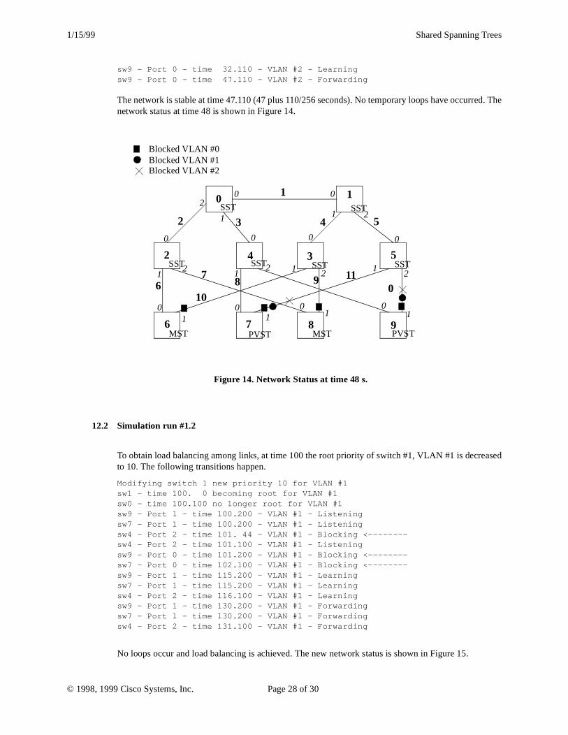
The network is stable at time 47.110 (47 plus 110/256 seconds). No temporary loops have occurrnetwork status at time 48 is shown in Figure 14.
Figure 14. Network Status at time 48 s.
12.2 Simulation run #1.2
To obtain load balancing among links, at time 100 the root priority of switch #1, VLAN #1 is decreto 10. The following transitions happen.
Modifying switch 1 new priority 10 for VLAN #1sw1 - time 100. 0 becoming root for VLAN #1sw0 - time 100.100 no longer root for VLAN #1sw9 - Port 1 - time 100.200 - VLAN #1 - Listeningsw7 - Port 1 - time 100.200 - VLAN #1 - Listeningsw4 - Port 2 - time 101. 44 - VLAN #1 - Blocking <--------sw4 - Port 2 - time 101.100 - VLAN #1 - Listeningsw9 - Port 0 - time 101.200 - VLAN #1 - Blocking <--------sw7 - Port 0 - time 102.100 - VLAN #1 - Blocking <--------sw9 - Port 1 - time 115.200 - VLAN #1 - Learningsw7 - Port 1 - time 115.200 - VLAN #1 - Learningsw4 - Port 2 - time 116.100 - VLAN #1 - Learningsw9 - Port 1 - time 130.200 - VLAN #1 - Forwardingsw7 - Port 1 - time 130.200 - VLAN #1 - Forwardingsw4 - Port 2 - time 131.100 - VLAN #1 - Forwarding
No loops occur and load balancing is achieved. The new network status is shown in Figure 15.
0 1
2 4 3 5
6 7 8 9
1
2 3 4 5
67
8 9
10
110
0
1
2
2 22 2
1
1 1 1 1
1111
0
0 0 0 0
0 0 0 0
2SST SST
SST SST SST SST
MST MSTPVST PVST
Blocked VLAN #0 Blocked VLAN #1 Blocked VLAN #2
© 1998, 1999 Cisco Systems, Inc. Page 28 of 30

1/15/99 Shared Spanning Trees
200
state.
Figure 15. Network status at time 132 s.
12.3 Simulation run #1.3Starting from the previous status, the root for the CST (VLAN #0) is moved to switch #8 at timecausing a temporary loop.
Modifying switch 8 new priority 10 for VLAN #0sw8 - Port 1 - time 200. 0 - VLAN #0 - Listeningsw8 - time 200. 0 becoming root for VLAN #0sw0 - time 200.200 no longer root for VLAN #0sw6 - Port 1 - time 200.200 - VLAN #0 - Listeningsw6 - Port 1 - time 200.200 - VLAN #0 - Blocking <--------sw1 - Port 0 - time 201.100 - VLAN #0 - Blocking <--------sw9 - Port 1 - time 201.200 - VLAN #0 - Listeningsw7 - Port 1 - time 201.200 - VLAN #0 - Listeningsw9 - Port 1 - time 201.200 - VLAN #0 - Blocking <--------sw7 - Port 1 - time 201.200 - VLAN #0 - Blocking <--------sw8 - Port 1 - time 215. 0 - VLAN #0 - Learningsw8 - Port 1 - time 230. 0 - VLAN #0 - ForwardingTime 230. 0 loop detected - sw0 - sw1 - sw3 - sw8 - sw2 - sw0 - for VAN #1Time 230. 0 loop detected - sw0 - sw1 - sw3 - sw8 - sw2 - sw0 - for VAN #2sw2 - Port 2 - time 230.210 - VLAN #1 - Blocking <--------
The temporary loop affects both VLAN #1 and #2 and it ends when sw2 - port 2 goes in blockingThe new network status is shown in Figure 16.
0 1
2 4 3 5
6 7 8 9
1
2 3 4 5
67
8 9
10
110
0
1
2
2 22 2
1
1 1 1 1
1111
0
0 0 0 0
0 00 0
2SST SST
SST SST SST SST
MST MSTPVST PVST
Blocked VLAN #0 Blocked VLAN #1 Blocked VLAN #2
© 1998, 1999 Cisco Systems, Inc. Page 29 of 30

1/15/99 Shared Spanning Trees
Figure 16. Network status at time 231 s.
0 1
2 4 3 5
6 7 8 9
1
2 3 4 5
67
8 9
10
110
0
1
2
2 22 2
1
1 1 1 1
1111
0
0 0 0 0
0 00 0
2SST SST
SST SST SST SST
MST MSTPVST PVST
Blocked VLAN #0 Blocked VLAN #1 Blocked VLAN #2
© 1998, 1999 Cisco Systems, Inc. Page 30 of 30