clear-com eclipse · • the cci-22 dual channel party-line interface has been damaged in any way....
TRANSCRIPT
CCI-22 DUAL CHANNEL PARTY-LINE INTERFACE
INSTRUCTION MANUAL
CLEAR-COM ECLIPSE
CCI-22 Dual Channel Party Line Interface Instruction Manual© 1997, 2005, 2008 Vitec Group Communications Ltd. All Rights Reserved.
Part Number 810307Z Rev. 3
Vitec Group Communications LLC850 Marina Village ParkwayAlameda, CA 94501U.S.A
Vitec Group Communications Ltd7400 Beach DriveIQ CambridgeCambridgeshireUnited KingdomCB25 9TP
Vitec Group CommunicationsRoom 1806, Hua Bin BuildingNo. 8 Yong An Dong LiJian Guo Men Wai AveChao Yang DistrictBeijing, P.R. China 100022
® Clear-Com, CellCom/FreeSpeak and the Clear-Com Communications Systems logo are registered trademarks of The Vitec Group plc.

CONTENTSOPERATION . . . . . . . . . . . . . . . . . . . . . . . . . . . . . . 1-1Introduction . . . . . . . . . . . . . . . . . . . . . . . . . . . . . . . . . . . . . . . . . . . . 1-1
Description . . . . . . . . . . . . . . . . . . . . . . . . . . . . . . . . . . . . . . . . . . 1-1Operation . . . . . . . . . . . . . . . . . . . . . . . . . . . . . . . . . . . . . . . . . . . . . 1-2
Level Controls . . . . . . . . . . . . . . . . . . . . . . . . . . . . . . . . . . . . . . . . 1-2Power LED . . . . . . . . . . . . . . . . . . . . . . . . . . . . . . . . . . . . . . . . . . 1-2
Send and Return Rejection Null Adjustment . . . . . . . . . . . . . . . 1-2
INSTALLATION . . . . . . . . . . . . . . . . . . . . . . . . . . . . 2-1Introduction . . . . . . . . . . . . . . . . . . . . . . . . . . . . . . . . . . . . . . . . . . . . 2-1Installation In Interface Frame . . . . . . . . . . . . . . . . . . . . . . . . . . . . . 2-1
Termination of Party-Lines . . . . . . . . . . . . . . . . . . . . . . . . . . . . . . 2-1Wiring . . . . . . . . . . . . . . . . . . . . . . . . . . . . . . . . . . . . . . . . . . . . . . . . 2-2
Clear-Com Party Lines General Discussion . . . . . . . . . . . . . . . . . 2-2Two Separate Party Lines . . . . . . . . . . . . . . . . . . . . . . . . . . . . . . . 2-3Multiple Clear-Com Beltpack Channels from One Power Supply . 2-4To Connect “RTS” 2-Channel 2-Wire Party-Lines . . . . . . . . . . . . . 2-7
Power from “Channel A” Line Only . . . . . . . . . . . . . . . . . . . . . . 2-8Two Isolated RTS Lines. . . . . . . . . . . . . . . . . . . . . . . . . . . . . . . 2-9
Adjustments . . . . . . . . . . . . . . . . . . . . . . . . . . . . . . . . . . . . . . . . . . 2-10Power LED . . . . . . . . . . . . . . . . . . . . . . . . . . . . . . . . . . . . . . . . . 2-10Level Controls . . . . . . . . . . . . . . . . . . . . . . . . . . . . . . . . . . . . . . . 2-10Audio Rejection Null Adjustment. . . . . . . . . . . . . . . . . . . . . . . . . 2-10
Configuration . . . . . . . . . . . . . . . . . . . . . . . . . . . . . . . . . . . . . . . . . 2-11
MAINTENANCE. . . . . . . . . . . . . . . . . . . . . . . . . . . . 3-1Introduction . . . . . . . . . . . . . . . . . . . . . . . . . . . . . . . . . . . . . . . . . . . . 3-1
Bill of Materials . . . . . . . . . . . . . . . . . . . . . . . . . . . . . . . . . . . . . . . 3-1Diagrams . . . . . . . . . . . . . . . . . . . . . . . . . . . . . . . . . . . . . . . . . . . . . 3-6
SPECIFICATIONS . . . . . . . . . . . . . . . . . . . . . . . . . . 4-1
LIMITED WARRANTY . . . . . . . . . . . . . . . . . . . . . . . W-IWarranty Period . . . . . . . . . . . . . . . . . . . . . . . . . . . . . . . . . . . . . . . .W-iTechnical Support . . . . . . . . . . . . . . . . . . . . . . . . . . . . . . . . . . . . . . .W-iWarranty Repairs and Returns . . . . . . . . . . . . . . . . . . . . . . . . . . . . W-iiNon-Warranty Repairs and Returns . . . . . . . . . . . . . . . . . . . . . . . . W-iiExtended Warranty . . . . . . . . . . . . . . . . . . . . . . . . . . . . . . . . . . . . . W-ii
Vitec Group CommunicationsCCI-22 Dual Channel Party-Line Interface Instruction Manual
i

Liability . . . . . . . . . . . . . . . . . . . . . . . . . . . . . . . . . . . . . . . . . . . . . . W-iii
Vitec Group CommunicationsCCI-22 Dual Channel Party-Line Interface Instruction Manual
ii

IMPORTANT SAFETY INSTRUCTIONSFor your safety, it is important to read and follow these instructions before operating a CCI-22 dual channel party-line interface: (1) WARNING: To reduce the risk of fire or electric shock, do not expose a CCI-22 dual channel party-line inteface to rain or moisture. Do not operate a CCI-22 dual channel party-line interface near water, or place objects containing liquid on it. Do not expose a CCI-22 dual channel party-line interface to splashing or dripping water.
(2) For proper ventilation, make sure ventilation openings are not blocked. Install the CCI-22 dual channel party-line interface according to the directions in the Installation chapter of this manual.
(3) Do not install a CCI-22 dual channel party-line interface near a heat source such as a radiator, heat register, stove, or other apparatus (including amplifiers) that produces heat. Do not place naked flame sources such as candles on or near a CCI-22 dual channel party-line interface.
(4) Only use attachments/accessories specified by Clear-Com Intercom Systems.
(5) Unplug the CCI-22 dual channel party-line interface during lightning storms or when unused for long periods of time.
(6) Refer all servicing to qualified service personnel. Servicing is required when:
• The CCI-22 dual channel party-line interface has been damaged in any way.
• Liquid has been spilled or objects have fallen into the CCI-22 dual channel party-line interface chassis.
• The CCI-22 dual channel party-line interface has been exposed to rain or moisture.
• The CCI-22 dual channel party-line interface does not operate normally.
• The CCI-22 dual channel party-line interface has been dropped.
Please familiarize yourself with the safety symbols in Figure 1. When you see these symbols on a CCI-22 dual channel party-line interface, they warn you of the potential danger of electric shock if the CCI-22 dual channel party-line interface is used improperly. They also refer you to important operating and maintenance instructions in the manual.
Please read and follow these instructions before operating a CCI-22 dual channel party-line interface.
Vitec Group CommunicationsCCI-22 Dual Channel Party-Line Interface Instruction Manual
v

Figure 1: Safety Symbols
CAUTIONRISK OF ELECTRIC SHOCK
DO NOT OPEN
This symbol alerts you to the presence of uninsulated dangerousvoltage within the product's enclosure that might be of sufficient magnitude to constitute a risk of electric shock. Do not open the product's case.
This symbol informs you that important operating and main-tenance instructions are included in the literature accompanyingthis product.
Vitec Group CommunicationsCCI-22 Dual Channel Party-Line Interface Instruction Manual
v i

OPERATIONINTRODUCTIONThis chapter describes how to use the CCI-22 dual party-line interface. You can use this chapter once the Eclipse matrix system has been correctly installed and configured with the Eclipse Configuration System, and when the CCI-22's internal jumpers have been set. For information on configuring the CCI-22 jumpers refer to Chapter 2, “Installation”.
DESCRIPTIONEach CCI-22 dual party-line interface can connect two independent external 2-wire party-line intercom systems to the Eclipse matrix. It will support Clear-Com and many other 2-wire analog party-line formats as well act as an independent 2/4wire party line interface for other 4wire intercom matrices.
The CCI-22 fully supports call signals between the matrix and a Clear-Com party-line; call signals between the matrix and other party-line types may not be fully supported. All call signal paths are optically isolated. All audio paths are transformer isolated, eliminating noise induced by ground loops in the party-line systems. "Send" and "receive" level controls are included on the front panel. The CCI-22 features sophisticated "sidetone nulling" circuitry.
The CCI-22 occupies one slot in an IMF-3 or IMF-102 interface module frame. Connections to the matrix are via 8-pin RJ-45 connectors on the rear panel. Connections to external party-lines are via 9-pin connectors on the rear panel.
The CCI-22's party-line circuits do not receive power from the matrix, but must be connected to an externally powered party-line.
More than one CCI-22 interface port may be assigned to one Eclipse system party-line label to create a single unified party-line. However, the nature of 2-wire to 4-wire hybrid conversions may limit the maximum number of external 2-wire party-lines that can be combined. Call signals to any one of the CCI-22 channels will reach destinations in the other CCI-22 channels in addition to the destination ports within the matrix.
When a CCI-22 interface port receives a call signal from a Clear-Com party-line, it will be sent to all ports in the matrix which have “listens” activated to the party-line at the time of the call signal. In addition, call signals can be programmed to signal specific stations (see the Configuration section of the Installation chapter).
CCI-22
Power
Send
Recv
C
L
R
Test
C
L
R
Test
Send
Recv
Null
Null
PL
PowerPL
1
VC
itec Group CommunicationsCI-22 Dual Channel Party-Line Interface Instruction Manual
1 - 1
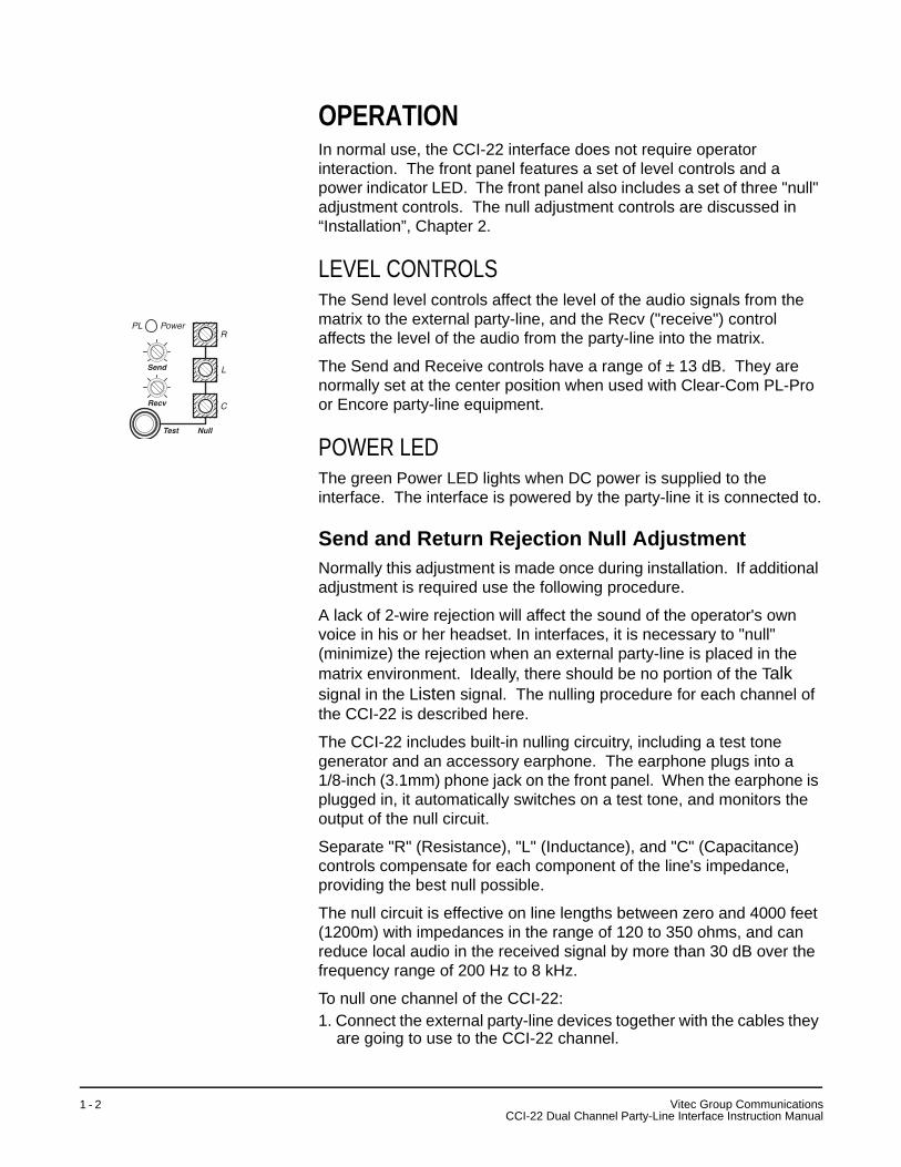
OPERATIONIn normal use, the CCI-22 interface does not require operator interaction. The front panel features a set of level controls and a power indicator LED. The front panel also includes a set of three "null" adjustment controls. The null adjustment controls are discussed in “Installation”, Chapter 2.
LEVEL CONTROLSThe Send level controls affect the level of the audio signals from the matrix to the external party-line, and the Recv ("receive") control affects the level of the audio from the party-line into the matrix.
The Send and Receive controls have a range of ± 13 dB. They are normally set at the center position when used with Clear-Com PL-Pro or Encore party-line equipment.
POWER LEDThe green Power LED lights when DC power is supplied to the interface. The interface is powered by the party-line it is connected to.
Send and Return Rejection Null AdjustmentNormally this adjustment is made once during installation. If additional adjustment is required use the following procedure.
A lack of 2-wire rejection will affect the sound of the operator's own voice in his or her headset. In interfaces, it is necessary to "null" (minimize) the rejection when an external party-line is placed in the matrix environment. Ideally, there should be no portion of the Talk signal in the Listen signal. The nulling procedure for each channel of the CCI-22 is described here.
The CCI-22 includes built-in nulling circuitry, including a test tone generator and an accessory earphone. The earphone plugs into a 1/8-inch (3.1mm) phone jack on the front panel. When the earphone is plugged in, it automatically switches on a test tone, and monitors the output of the null circuit.
Separate "R" (Resistance), "L" (Inductance), and "C" (Capacitance) controls compensate for each component of the line's impedance, providing the best null possible.
The null circuit is effective on line lengths between zero and 4000 feet (1200m) with impedances in the range of 120 to 350 ohms, and can reduce local audio in the received signal by more than 30 dB over the frequency range of 200 Hz to 8 kHz.
To null one channel of the CCI-22:1. Connect the external party-line devices together with the cables they
are going to use to the CCI-22 channel.
Power
Send
Recv C
L
R
Test Null
PL
Vitec Group CommunicationsCCI-22 Dual Channel Party-Line Interface Instruction Manual
1 - 2
2. Plug the accessory earphone into the front panel jack labeled "Test". This will disconnect the interface from the matrix and enable the test oscillator. The oscillator produces a square wave with both low and high harmonics, allowing you to test all frequencies. The test tone pulses approximately every half-second.
3. While listening to the test tone in the earphone, adjust the "R" control until the tone is at a minimum.
4. Repeat Step 3 with the "L" and "C" controls. Because these controls interact with each other, you will need to repeat steps 3 and 4 several times before you will have minimized the test tone. Continue adjustment until the tone is virtually inaudible. If an almost complete null cannot be obtained, it is likely that something is wrong either with the wiring in the external party-line, or with one of the other devices attached to the external party-line. Steps 5 through 9 are troubleshooting hints.
5. If the "R" control is turned fully counter-clockwise, the line has either more than one termination, or an excessive resistive load.
6. If the "R" control is fully clockwise, then the line has no termination.7. The "L" control compensates for the low-frequency inductive and
capacitive elements of the external party-line. If the "L" control is fully turned in either direction, it is likely that there is a problem in the external party-line. When a Clear-Com party-line is connected, the "L" control should be just to one side of its mid-pot position.
8. The "C" control compensates for cable capacitance; the setting depends on the length of the line. If the "C" control is fully counter-clockwise, this indicates a very short line (under ten feet); this is a valid setting for a short line.
9. If the "C" control is fully clockwise, this indicates an excessively long line (over 4,000 feet or 1200m).
VC
itec Group CommunicationsCI-22 Dual Channel Party-Line Interface Instruction Manual
1 - 3

Vitec Group CommunicationsCCI-22 Dual Channel Party-Line Interface Instruction Manual
1 - 4
INSTALLATIONINTRODUCTIONThis chapter describes the installation of the CCI-22 dual party-line interface, including setting internal jumpers, wiring to external devices, and setting front-panel controls and indicators.
INSTALLATION IN INTERFACE FRAMETo install the CCI-22 interface module in the IMF-3 or IMF-102 interface frame: 1. Select a slot in which to install the interface.2. Remove the blank plate covering the slot.3. Set any Party-Line Termination Jumpers as necessary.4. Slide the CCI-22 in the slot and ensure that the card is fully seated.5. Tighten the CCI-22’s front-panel mounting screws.
TERMINATION OF PARTY-LINESA “Clear-Com termination network” (also known simply as a “termination”) is a Resistor-Capacitor (RC) circuit that must be connected between the Audio and Ground lines of any Clear-Com party-line. To ensure correct operation of the external party-line, only one termination can be installed on any given party-line.
A party-line termination is normally provided by the component powering the party-line. Although the CCI-22 is not designed to supply power to an external party-line system, each channel of the CCI-22 features a Clear-Com termination circuit that can be connected to the party-line by installing a jumper. This termination network is not normally connected, and should only be connected in the rare case that the external party-line does not include a termination circuit. An example of the use of these termination networks is Figure 2-6 on page 2-6.
If a party-line has more than one termination circuit, it will not null correctly (see “Rejection Null Adjustment” on page 2-10). The most common symptom of this is when the line does not null, even though the “R” null control has been turned all the way counter-clockwise. If this happens, check all components connected to the party-line that are capable of providing a termination to be sure that only one termination is connected to the party-line.
The two termination circuits on the CCI-22 connect to the channel A and B party-lines; they are enabled and disabled by the jumpers at JP100 (which controls the termination circuit for channel A) and JP200 (which controls the termination for channel B). JP100 and JP200 are
2
VC
itec Group CommunicationsCI-22 Dual Channel Party-Line Interface Instruction Manual
2 - 1

located near the center of the CCI-22 main circuit board, and are shown as a detail in the assembly drawing for the CCI-22 main circuit board in the Maintenance Chapter. When either jumper is next to the label “B”, its termination is disabled; moving the jumper next to the label “A” enables the termination.
WIRINGThe CCI-22 interfaces are connected to the matrix frame through the two RJ-45 connectors on the IMF-3 or IMF-102 rear-panel assembly (part no. 710538Z) to which CCI-22 is connected. For connection to a matrix frame refer to the “Installation in Interface Frame” on page 2-1. For internal jumper settings and adjustments refer to “Adjustments” on page 2-10.
The “user” side of the CCI-22 for each channel is on a pair of DB-9M connectors on the rear of the interface frame. Figure 2-1 shows the pinout of either one of these connectors. Both DB-9Ms are paralleled such that both party-line channels are available on each connector. It is possible to wire one DB-9 connector as channel #1, the second DB-9M as channel #2, or bring both channels out either DB connector separately or create a TW type party-line connection.
Figure 2-1: Pinout of the DB-9M Interface I/O Connectors
CLEAR-COM PARTY LINES GENERAL DISCUSSIONStations on Clear-Com party-lines are connected with two-conductor shielded microphone cable. One conductor carries the DC power (28 to 30 V), while the other carries the duplex two-way intercom audio signal and DC “Call Light” signaling. The shield acts as common ground for both the power and signal.
Power to the CCI-22 interface channels must be provided by the external party-line. The power connection for each channel is the “+30 VDC Power” pin on the appropriate DB-9M Interface I/O connector located on the rear-panel assembly. The CCI-22 channel is essentially just another “beltpack” on the party-line.
6
7
8
9
1
2
3
4
5
Channel 2 Channel 1
CC/RTS
Ground
+30 VDC Power
Audio
CC/RTS
Ground
+30 VDC Power
Audio
Chassis Ground
Vitec Group CommunicationsCCI-22 Dual Channel Party-Line Interface Instruction Manual
2 - 2

The power pin has a DC filtering circuitry to provide a high impedance for the audio so the power can be received from a “powered line or TW line” as is common with RTS systems. For TW operation tie the AUDIO and POWER pins together.
Each party-line channel requires exactly one termination circuit. The termination circuit is usually built into the system component providing the party-line’s power. Connecting more than one termination circuit to a party-line will impair the null and degrade the line’s audio quality.
When a CCI-22 party-line channel is connected to a Clear-Com party-line, the Clear-Com/Other Select pin must be left floating. Grounding this pin selects the RTS mode, which is incompatible with Clear-Com party-lines.
TWO SEPARATE PARTY LINESThe diagram in Figure 2-2 shows the CCI-22’s two channels connecting two independent external party lines to the matrix. Each external party line provides its own power and termination. The wiring diagrams in Figure 2-3 and Figure 2-4 show an external switch on the Clear-Com/Other Select pin; this switch allows the CCI-22 channel to be used on either Clear-Com or RTS party-lines.
In the wiring diagram in Figure 2-3, all connections to the CCI-22 are made using only one of the CCI-22’s two parallel DB-9M connectors. The wiring diagram in Figure 2-4 shows the same connections as Figure 2-3, except that each DB-9M connector is wired separately. Use the wiring method that is most convenient for the installation.
Figure 2-2: Two External Party-Lines Connected to the CCI-22
CCI-22
Matrix
Clear-ComPower Supplyw/ Termination
Beltpack Beltpack Beltpack
Clear-ComPower Supplyw/ Termination
Beltpack Beltpack Beltpack
VC
itec Group CommunicationsCI-22 Dual Channel Party-Line Interface Instruction Manual
2 - 3

Figure 2-3: One DB-9 Connected to the CCI-22
Figure 2-4: Two Separate DB-9 Connections to the CCI-22
MULTIPLE CLEAR-COM BELTPACK CHANNELS FROM ONE POWER SUPPLYA single two-output power supply can provide power for more than two CCI-22 party-line channels. In this case the power supply provides power for each party-line, but each CCI-22 channel provides the termination for each party-line. Many Clear-Com power supplies have a switch to enable or disable the termination circuits from each of its outputs. If using such a supply:1. Disable the terminations by using the switch.2. Connect the PS-702 output to all of the CCI-22 channels to be
powered using the standard three connections in the XLR connector.
6
7
8
9
1
2
3
4
5
2
3
1 2
3
1
Optional Clear-Com/RTSExternal Switch
Two 0.01 uF7-in. 18 gauge wire
Spade Lug toChassis Ground
on IMF-3
XLR XLR
Channel 1 Channel 2
6
7
8
9
1
2
3
4
5
6
7
8
9
1
2
3
4
5
2
3
1 2
3
1
Optional Clear-Com/RTSExternal Switch
0.01 uF 0.01 uF
7-in. 18 gauge wire7-in. 18 gauge wire
Spade Lug toChassis Ground
on IMF-3
Spade Lug toChassis Ground
on IMF-3
XLRXLR
Channel 1 Channel 2
Vitec Group CommunicationsCCI-22 Dual Channel Party-Line Interface Instruction Manual
2 - 4

3. Set the termination jumper for each CCI-22 channel to position “A” (termination connected) as described in “Termination of Party-Lines.”
If the power supply does not have a termination-disconnect switch, wire the system as shown in Figure 2-5 on page 2-5. In this configuration, only the power supply channel’s power and ground lines are connected to the party-line.
Note: Do not connect the power supply output’s terminated audio line to the party line.
Do not let the power supply output’s current rating exceed the total current drawn by the devices powered.
Figure 2-5: Diagram of One Power Supply with Four CCI-22 Termina-tions
Matrix
Beltpack #1 Beltpack #2
Beltpack #3 Beltpack #4
Clear-ComPower Supply
CCI-22
CCI-22
Set Terminations in CCI-22
Power and GroundConnections Only
VC
itec Group CommunicationsCI-22 Dual Channel Party-Line Interface Instruction Manual
2 - 5

Figure 2-6: Wiring of One Power Supply for More than Two Party-Line Channels
Note: In Figure 2-6 beltpacks #1 and #3 are on one Party Line intercom channel while beltpacks #2 and #4 are on the other Party Line intercom channel.
6
7
8
9
1
2
3
4
5
23
1 23
1
Two 0.01uF
7-in. 18 gauge wire
Spade Lug toChassis Ground
on IMF-3
Beltpack #1XLR
Beltpack #2XLR
6
7
8
9
1
2
3
4
5
23
1 23
1
23
1Two 0.01
uF7-in. 18 gauge wire
Spade Lug toChassis Ground
on IMF-3
Beltpack #3XLR
Beltpack #4XLR
To Clear-ComPS-702
Power Supply
DB-9F OnFirst CCI-22
DB-9F OnSecond CCI-22
Vitec Group CommunicationsCCI-22 Dual Channel Party-Line Interface Instruction Manual
2 - 6

TO CONNECT “RTS” 2-CHANNEL 2-WIRE PARTY-LINESStations on RTS 2-channel 2-wire party lines are connected with 2-conductor shielded cable. One of the two shielded conductors carries both the DC power and the audio signal for one channel, while the other conductor carries audio only providing two channels per cable. The shield is a common ground for both channels. The matrix can be connected to a 2-channel 2-conductor “RTS” line using the CCI-22’s two channels. The CCI-22 does not support RTS call signals.
Power to the CCI-22’s channels must be provided by the external party line. The power connection for each channel is the “+30 VDC Power” pin on the appropriate DB9-M Interface I/O connector on the rear-panel assembly. When connected to an RTS system, each channel’s power input circuit will filter out the audio signal on the RTS line.
Figure 2-7: Connection Diagram of CCI-22 DB-9 to RTS XLR
Audio is fed to each CCI-22 channel via the “audio” pin on the appropriate DB9-M Interface I/O connector on the rear-panel assembly. When connected to an RTS system, each channel’s audio input circuit will filter out the DC power on the RTS line.
The Clear-Com/RTS pin must be grounded when a CCI-22 party-line channel is connected to an RTS party line. Leaving this pin floating selects “Clear-Com” mode, which is incompatible with RTS party lines.
The termination jumper of each CCI-22 channel must be set to “B” (termination disabled).
CCI-22 channels can be connected to RTS party lines in a variety of configurations, depending on how the power and grounds are connected between the party line and the CCI-22 channel. The following sections describe the options.
CC/RTSGND Chan-1
+30 VDC PowerChan-1 AUDIONA
CC/RTS
GND Chan-2+30 VDC Power
Chan-2 AUDIO
1
23
4
5
67
IMF-3/CCI-22DB9
RTS-TWXLR
1
2
3
GND
+VDC/Ch-1 AUDIO
Ch-2 AUDIO
VC
itec Group CommunicationsCI-22 Dual Channel Party-Line Interface Instruction Manual
2 - 7
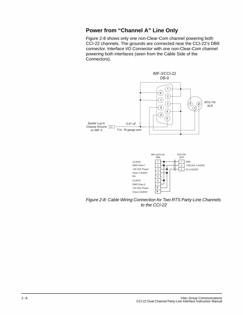
Power from “Channel A” Line OnlyFigure 2-8 shows only one non-Clear-Com channel powering both CCI-22 channels. The grounds are connected near the CCI-22’s DB9 connector. Interface I/O Connector with one non-Clear-Com channel powering both interfaces (seen from the Cable Side of the Connectors).
Figure 2-8: Cable Wiring Connection for Two RTS Party-Line Channels to the CCI-22
6
7
8
9
1
2
3
4
5
23
1
0.01 uF
7-in. 18 gauge wire
Spade Lug toChassis Ground
on IMF-3
RTS-TWXLR
IMF-3/CCI-22DB-9
CC/RTSGND Chan-1
+30 VDC PowerChan-1 AUDIONA
CC/RTS
GND Chan-2+30 VDC Power
Chan-2 AUDIO
1
23
4
5
67
IMF-3/CCI-22DB9
RTS-TWXLR
1
2
3
GND
+VDC/Ch-1 AUDIO
Ch-2 AUDIO
Vitec Group CommunicationsCCI-22 Dual Channel Party-Line Interface Instruction Manual
2 - 8
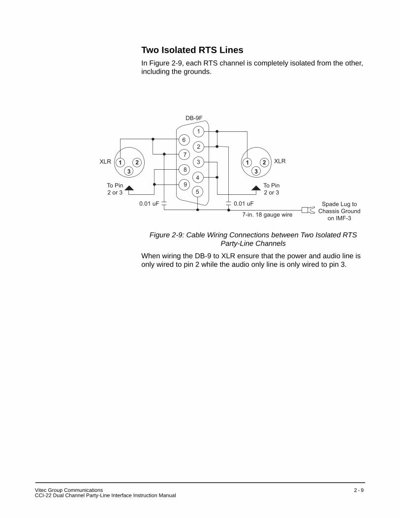
Two Isolated RTS LinesIn Figure 2-9, each RTS channel is completely isolated from the other, including the grounds.
Figure 2-9: Cable Wiring Connections between Two Isolated RTS Party-Line Channels
When wiring the DB-9 to XLR ensure that the power and audio line is only wired to pin 2 while the audio only line is only wired to pin 3.
6
7
8
9
1
2
3
4
5
23
123
1
7-in. 18 gauge wire
Spade Lug toChassis Ground
on IMF-3
XLR
DB-9F
XLR
To Pin2 or 3
To Pin2 or 3
0.01 uF0.01 uF
VC
itec Group CommunicationsCI-22 Dual Channel Party-Line Interface Instruction Manual
2 - 9
ADJUSTMENTSPOWER LEDThe green “PL Power” LEDs indicate whether the interface channels are getting +30 VDC power from the external party line to which they are connected.
LEVEL CONTROLSThe “Send” level controls affect the level of the audio signals from the matrix to the external party line.
The “Recv” level controls affect the level of the audio from the party line to the matrix. The level controls have a range of ±13 dB; they are normally set to the midrange position.
AUDIO REJECTION NULL ADJUSTMENTSidetone is the sound of the operator’s voice in his headset. In interfaces, it is necessary to null (minimize) the sidetone as much as possible when an external party line is placed in the matrix environment. Ideally, there should be no portion of the talk signal in the listen signal.The CCI-22 features sophisticated built-in nulling circuitry, including a test-tone generator and an accessory earphone. The earphone plugs into a phone jack on the front panel. When the earphone is plugged in, it automatically switches on a test tone and monitors the output of the null circuit.
Separate “R” (resistance), “L” (inductance), and “C” (capacitance) controls compensate for each component of the line’s impedance, providing the best null possible.
The null circuit is effective on line lengths between zero and 4000 ft (1200m) with impedances in the range of 120 to 350 ohms, and can reduce local audio in the received signal by more than 30 dB over the frequency range of 200 Hz to 8 kHz.
To null one channel of the CCI-22:1. Connect the external party-line devices to the CCI-22 channel. Make
sure that any connected devices do not have their microphones on.2. Plug the accessory earphone into the front-panel jack labeled “Test.”
This will disconnect the interface from the matrix and enable a test oscillator. The oscillator produces a square wave with both low and high harmonics, allowing testing of all frequencies. The test tone pulses approximately every 0.5 seconds.
3. While listening to the test tone in the earphone, adjust the “R” control until the tone is at a minimum.
4. Repeat Step 3 with the “L” and “C” controls. Because these controls interact, steps 3 and 4 will have to be repeated several times the
Vitec Group CommunicationsCCI-22 Dual Channel Party-Line Interface Instruction Manual
2 - 1 0

test tone is minimized. Continue adjustment until the tone is minimal. If a deep null cannot be obtained, it is likely that something is wrong either with the wiring in the external party line or with one of the other devices attached to it.
Following are some troubleshooting hints if a deep null cannot be obtained:
• If the “R” control is turned fully counter-clockwise, the line has either more than one termination, or an excessive resistive load.
• If the “R” control is fully clockwise, then the line has no termination.
• The “L” control compensates for the low-frequency inductive and capacitive elements the wiring of the external party line presents to the line. If the “L” control is fully turned in either direction, it is likely that there is a problem in the external party line. When a Clear-Com party line is connected, the “L” control should be just to one side of its mid-pot position.
• The “C” control compensates for cable capacitance; the setting depends on the length of the line. If the “C” control is fully counter-clockwise, it indicates a very short line (under 10 ft.); this is a valid setting for a short line.
• If the “C” control is fully clockwise, it indicates an excessively long line (more than 4000 ft.).
CONFIGURATIONRefer to the Eclipse Configuration System Instruction Manual for information on configuring parameters from the matrix.
VC
itec Group CommunicationsCI-22 Dual Channel Party-Line Interface Instruction Manual
2 - 1 1

Vitec Group CommunicationsCCI-22 Dual Channel Party-Line Interface Instruction Manual
2 - 1 2
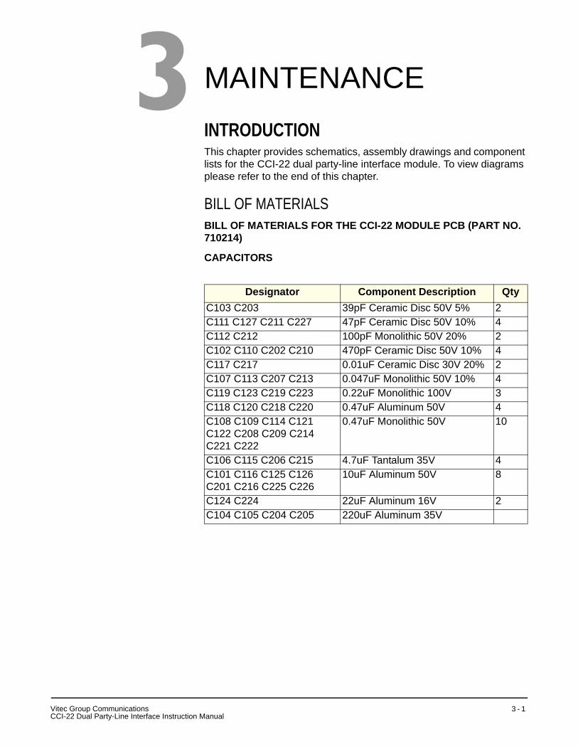
MAINTENANCEINTRODUCTIONThis chapter provides schematics, assembly drawings and component lists for the CCI-22 dual party-line interface module. To view diagrams please refer to the end of this chapter.
BILL OF MATERIALSBILL OF MATERIALS FOR THE CCI-22 MODULE PCB (PART NO. 710214)
CAPACITORS
Designator Component Description QtyC103 C203 39pF Ceramic Disc 50V 5% 2C111 C127 C211 C227 47pF Ceramic Disc 50V 10% 4C112 C212 100pF Monolithic 50V 20% 2C102 C110 C202 C210 470pF Ceramic Disc 50V 10% 4C117 C217 0.01uF Ceramic Disc 30V 20% 2C107 C113 C207 C213 0.047uF Monolithic 50V 10% 4C119 C123 C219 C223 0.22uF Monolithic 100V 3C118 C120 C218 C220 0.47uF Aluminum 50V 4C108 C109 C114 C121C122 C208 C209 C214C221 C222
0.47uF Monolithic 50V 10
C106 C115 C206 C215 4.7uF Tantalum 35V 4C101 C116 C125 C126C201 C216 C225 C226
10uF Aluminum 50V 8
C124 C224 22uF Aluminum 16V 2C104 C105 C204 C205 220uF Aluminum 35V
3
Vitec Group CommunicationsCCI-22 Dual Party-Line Interface Instruction Manual
3 - 1
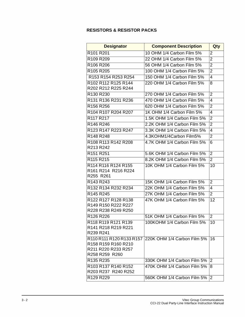
RESISTORS & RESISTOR PACKS
Designator Component Description QtyR101 R201 10 OHM 1/4 Carbon Film 5% 2R109 R209 22 OHM 1/4 Carbon Film 5% 2R106 R206 56 OHM 1/4 Carbon Film 5% 2R105 R205 100 OHM 1/4 Carbon Film 5% 2 R153 R154 R253 R254 150 OHM 1/4 Carbon Film 5% 4R102 R112 R125 R144 R202 R212 R225 R244
220 OHM 1/4 Carbon Film 5% 8
R130 R230 270 OHM 1/4 Carbon Film 5% 2R131 R136 R231 R236 470 OHM 1/4 Carbon Film 5% 4R156 R256 620 OHM 1/4 Carbon Film 5% 2R104 R107 R204 R207 1K OHM 1/4 Carbon Film 5% 4R117 R217 1.5K OHM 1/4 Carbon Film 5% 2R146 R246 2.2K OHM 1/4 Carbon Film 5% 2R123 R147 R223 R247 3.3K OHM 1/4 Carbon Film 5% 4R148 R248 4.3KOHM1/4Carbon Film5% 2R108 R113 R142 R208 R213 R242
4.7K OHM 1/4 Carbon Film 5% 6
R151 R251 5.6K OHM 1/4 Carbon Film 5% 2R115 R215 8.2K OHM 1/4 Carbon Film 5% 2R114 R116 R124 R155 R161 R214 R216 R224 R255 R261
10K OHM 1/4 Carbon Film 5% 10
R143 R243 15K OHM 1/4 Carbon Film 5% 2R132 R134 R232 R234 22K OHM 1/4 Carbon Film 5% 4R145 R245 27K OHM 1/4 Carbon Film 5% 2R122 R127 R128 R138 R149 R150 R222 R227 R228 R238 R249 R250
47K OHM 1/4 Carbon Film 5% 12
R126 R226 51K OHM 1/4 Carbon Film 5% 2R118 R119 R121 R139 R141 R218 R219 R221 R239 R241
100KOHM 1/4 Carbon Film 5% 10
R110 R111 R120 R133 R157 R158 R159 R160 R210 R211 R220 R233 R257 R258 R259 R260
220K OHM 1/4 Carbon Film 5% 16
R135 R235 330K OHM 1/4 Carbon Film 5% 2R103 R137 R140 R152 R203 R237 R240 R252
470K OHM 1/4 Carbon Film 5% 8
R129 R229 560K OHM 1/4 Carbon Film 5% 2
Vitec Group CommunicationsCCI-22 Dual Party-Line Interface Instruction Manual
3 - 2

DIODES AND TRANSISTORS
INTEGRATED CIRCUITS
Designator Component Description QtyD102 D104 D202 D204 Diode 1N4001 RECT 1A 50PIV 4D103 D105 D106 D107 D203 D205 D206 D207
Diode 1N4148 SIGNAL 10MA 75PIV
8
D108 D208 Diode 1N957B ZENER 6.8V .4W 5%
2
Q105 Q107 Q205 Q207 Transistor 2N2222 NPN 30V 4Q103 Q203 Transistor2N4401 NPN 40V 2Q108 Q109 Q110 Q111 Q208 Q209 Q210 Q211
Transistor J174 JFET PCHAN 8V VGS
8
Q106 Q206 Transistor MPS-A13 NPN 30V DARL
2
Q101 Q102 Q201 Q202 Transistor MPS-A55 PNP 60V 4Q104 Q204 Transistor MPS-A63 PNP 30V
DARL2
Designator Component Description QtyIC105 IC106 IC205 IC206 Analog IC 4N26 OPTO COM-
PILER4
IC103 IC104 IC203 IC204 Logic Chip 4001 CMOS QUAD 2 IN NOR
4
IC102 IC202 Op Amp LM741 IC OP AMP 8-PIN DIP
2
IC101 IC201 Op Amp NE5532 DUAL LO NOISE OP AMP
2
Vitec Group CommunicationsCCI-22 Dual Party-Line Interface Instruction Manual
3 - 3

MISCELLANEOUS
BILL OF MATERIALS FOR THE CCI-22 NULL PCB (PART NO. 710215)
CAPACITORS
RESISTORS & RESISTOR PACKS
Designator Component Description QtyJ100 J200 Connector 3 COND MINI
PHONE JACK2
D101 D201 LED T1 RT ANG 5mA GREEN 2P101 P201 Pot 10K TRIMPOT 2P102 P202 Pot 50K TRIMPOT 2T101 T102 T201 T202 Transformer 600 OHM 1:1
AUDIO TRANS4
Designator Component Description QtyC107 C207 15 pF Ceramic Disc 1000V 10% 2C114 C214 39 pF Ceramic Disc 50V 5% 2C103 C203 180 pF Monolithic 50V 2C102 C202 200 pF Ceramic Disc 50V 10% 2C101 C201 470 pF Ceramic Disc 50V 10% 2C106 C109 C206 C209 820 pF Ceramic Disc 50V 10% 4C112 C212 0.0047 uF Mylar 50V 10% 2C116 C117 C216 C217 0.01 uF Monolithic 50V 20% 4C105 C111 C205 C211 0.047 uF Metal Polyester 50V
10%4
C110 C113 C210 C213 0.22 uF Monolithic 100V 4C115 C215 1 uF Aluminum 50V 10% 2C104 C204 4.7 uF Aluminum 50V 2
Designator Component Description QtyR103 R203 430OHM1/4Carbon Film5%R114 R214 470OHM1/4Carbon Film5%R112 R212 1K OHM 1/4 Carbon Film 5% 2R109 R113 R209 R213 1.5K OHM 1/4 Carbon Film 5% 4R111 R211 3.3K OHM 1/4 Carbon Film 5% 2R106 R206 15K OHM 1/4 Carbon Film 5% 2
Vitec Group CommunicationsCCI-22 Dual Party-Line Interface Instruction Manual
3 - 4
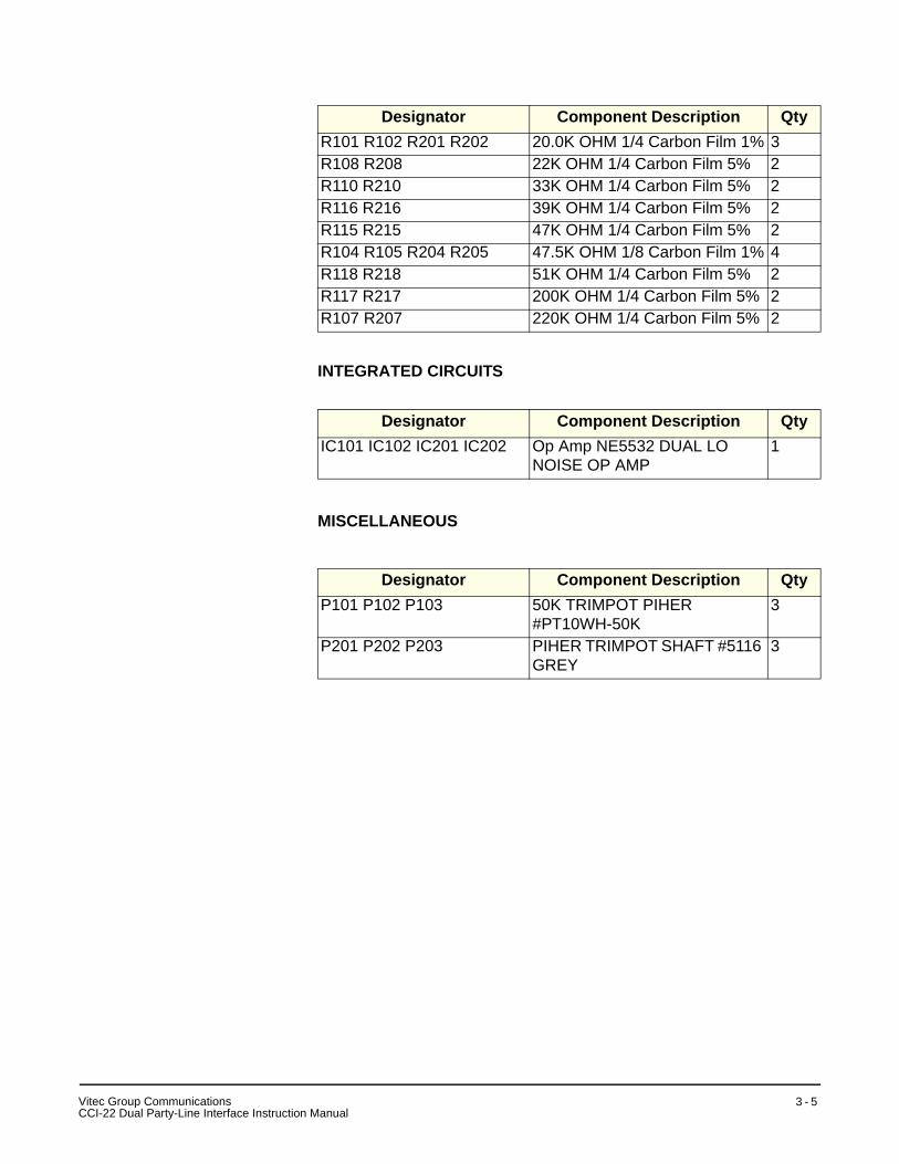
INTEGRATED CIRCUITS
MISCELLANEOUS
R101 R102 R201 R202 20.0K OHM 1/4 Carbon Film 1% 3R108 R208 22K OHM 1/4 Carbon Film 5% 2R110 R210 33K OHM 1/4 Carbon Film 5% 2R116 R216 39K OHM 1/4 Carbon Film 5% 2R115 R215 47K OHM 1/4 Carbon Film 5% 2R104 R105 R204 R205 47.5K OHM 1/8 Carbon Film 1% 4R118 R218 51K OHM 1/4 Carbon Film 5% 2R117 R217 200K OHM 1/4 Carbon Film 5% 2R107 R207 220K OHM 1/4 Carbon Film 5% 2
Designator Component Description QtyIC101 IC102 IC201 IC202 Op Amp NE5532 DUAL LO
NOISE OP AMP1
Designator Component Description QtyP101 P102 P103 50K TRIMPOT PIHER
#PT10WH-50K3
P201 P202 P203 PIHER TRIMPOT SHAFT #5116 GREY
3
Designator Component Description Qty
VC
itec Group CommunicationsCI-22 Dual Party-Line Interface Instruction Manual
3 - 5

DIAGRAMS
Figure 3-1: Block Diagram - CCI-22 Interface
Vitec Group CommunicationsCCI-22 Dual Party-Line Interface Instruction Manual
3 - 6

Figure 3-2: Schematic - CCI-22 Interface (Part No. 719214)
IC206IC206
IC106IC106D208D208 D108
D108
R260R260R224R224
R223R223
R218R218
R217R217R201R201
R160R160R124R124
R123R123
R118R118
R117R117
R101R101
J2J2
T202T202
T102T102
Q210Q210
Q110Q110C210
C210C209C209
C109C109C110C110
R247R247 R237R237 R226
R226
R147R147 R137
R137 R126R126
Q211Q211
Q208Q208
IC201IC201
P202P202
R246R246
R245R245
R208R208
J200J200
C227C227
C229C229
R249R249
C225C225
R251R251
R254R254R250R250C221C221
C222C222
R259R259R257R257
R252R252
R248R248
P102P102
P201P201
P101P101
D201D201
D101D101
J100J100
Q111Q111
Q108Q108
IC101IC101
R148R148
R145R145
R108R108T201T201 C127C127
R256R256R232R232
C230C230
C223C223
R231R231
R230R230
C207C207
C212C212
C123C123
C125C125 R149R149
C224C224
R253R253
C208C208
R228R228
R227R227
C211C211
R234R234
R229R229 C121C121 R151R151
R154R154
R150R150
C122C122
R159R159R157R157
R152R152
R156R156
R153R153
R132R132
T101T101
C129C129C107C107
R146R146 R131R131
R130R130
C112C112
C130C130
C124C124
C108C108
R128R128
R127R127
C111C111
R134R134
R129R129
Q209Q209
Q206Q206
C217C217
R242R242R241R241
R240R240R239R239
R238R238R235R235
R216R216R215R215
R214R214
C226
C226
R258R258
R243R243R236R236R233R233
R213R213
R212R212
JP200JP200
B A
Q203Q203
C203C203
C204C204
R209R209
C205C205
R207R207R206R206
R205R205R204R204
Q202Q202
D203D203
C202C202R203R203
R202R202
IC202IC202
IC102IC102
C215C215
C126C126
R244R244
R144R144
Q109Q109
R141R141
R140R140R139R139
R138R138R135R135
R116R116R115R115R114R114
IC203IC203
C214C214
C213C213
C216C216
C228C228
R158R158
R136R136
R133R133
R143R143
IC204IC204
R113R113 R112
R112
JP100JP100
B A
IC103IC103
C114C114
C128C128
R142R142
C116C116
C113C113
IC104IC104
C117C117
C115C115
C103C103
R109R109
R105R105R104R104
Q103Q103
C220C220 R261R261
R222R222
D204D204
D207D207
C206C206R255R255
R211R211
R210R210
C104C104
C105C105
Q204Q204
D206D206D205D205
C219C219
R221R221R220R220
R219R219
Q205Q205
C218C218
R106R106
Q102Q102
R107R107
D103D103
C102C102R103R103
R102R102
C120C120
R161R161
D104D104
D107D107
C106C106R155R155
R111R111
R110R110
Q104Q104
D106D106D105D105
C119C119
R121R121R120R120
R119R119
Q105Q105
R122R122
Q106Q106 C118
C118
Q207Q207
J1J1
D202D202
C201C201
Q201Q201
3232 3030
COPYRIGHT (C) 2000COPYRIGHT (C) 2000
Made in USA
Made in USA
IC205IC205
R225R225
Q101Q101
D102D102
C101C101
2525
2020 1515 1010
ASSY #710214ASSY #710214
CLEAR-COMCLEAR-COM
IC105IC105
R125R125
Q107Q107
CA
5 1
Vitec Group CommunicationsCCI-22 Dual Party-Line Interface Instruction Manual
3 - 7
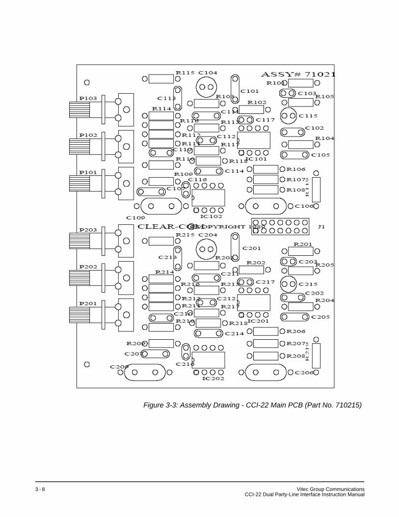
Figure 3-3: Assembly Drawing - CCI-22 Main PCB (Part No. 710215)
Vitec Group CommunicationsCCI-22 Dual Party-Line Interface Instruction Manual
3 - 8

SPECIFICATIONSNote: 0 dBu is referenced to 0.775 V RMS
Party-Line Characteristics (Clear-Com Mode)Audio Level -15 dBu nominalClipping Level +3 dBu minimumImpedance Greater than 10k ohms (bridging)Frequency Response 200 to 10k Hz, ±3 dB
Party-Line Characteristics (RTS Mode)Audio Level -10 dBu nominalClipping Level +5 dBu minimumImpedance Greater than 10k ohms (bridging)Frequency Response 200 to 10k Hz, ±3 dB
Call Signal Input (Clear-Com Mode)Threshold 4 VDC on Audio Line
Call Signal Output (Clear-Com Mode)Level 11 VDC Minimum on Audio Line
Nulling CapabilityLine Length 0 to 4000 ft (1200m)Line Impedance 120 to 350 ohmsDepth of Null Greater than 30 dB, 200 to 8k Hz
DC IsolationFrom the IMF-3 frame to an external input or output: >10 Mega-ohms.
Power Consumption (Each Channel)Maximum 40 mA at 20 to 30 VDC
(Power is supplied by the externalparty-line)
ConnectorsRJ-45 “To Matrix” 2DB-9M “Interface I/O” 21/8 in. Phone Jack 1 on Front Panel
Operating EnvironmentTemperature Between 0° and 70° C (32° to 150° F)
Package DimensionsFrame Slot Usage 1 slot of IMF-3 or IMF-102 frame Weight 0.54 lb (0.22 kg)
4
VC
itec Group CommunicationsCI-22 Dual Channel Party-Line Interface Instruction Manual
4 - 1

Notice About SpecificationsWhile Vitec Group Communications makes every attempt to maintain the accuracy of the information contained in its product manuals, that information is subject to change without notice. Performance specifications included in this manual are design-center specifications and are included for customer guidance and to facilitate system installation. Actual operating performance may vary.
Vitec Group CommunicationsCCI-22 Dual Channel Party-Line Interface Instruction Manual
4 - 2

LIMITED WARRANTYVitec Group Communications (VGC) warrants that at the time of purchase, the equipment supplied complies with any specification in the order confirmation when used under normal conditions, and is free from defects in workmanship and materials during the warranty period.
During the warranty period VGC, or any service company authorized by VGC, will in a commercially reasonable time remedy defects in materials, design, and workmanship free of charge by repairing, or should VGC in its discretion deem it necessary, replacing the product in accordance with this limited warranty. In no event will VGC be responsible for incidental, consequential, or special loss or damage, however caused.
WARRANTY PERIODThe product may consist of several parts, each covered by a different warranty period. The warranty periods are:
• Cables, accessories, components, and consumable items have a limited warranty of 90 days.
• Headsets, handsets, microphones, and spare parts have a limited warranty of one year.
• UHF wireless IFB products have a limited warranty of one year.
• UHF wireless intercom systems have a limited warranty of three years.
• All other Clear-Com and Drake brand systems and products, including beltpacks, have a limited warranty of two years.
The warranty starts at the time of the product’s original purchase. The warranty start date for contracts which include installation and commissioning will commence from the earlier of date of the Site Acceptance Test or three months from purchase.
TECHNICAL SUPPORT To ensure complete and timely support to its customers, VGC’s User Support Center is staffed by qualified technical personnel. Telephone and email technical support is offered worldwide by the User Support Center.
The User Support Center is available to VGC’s customers during the full course of their warranty period.
Instructions for reaching VGC’s User Support Centers are given below.
Return Material Authorization (RMA) numbers are required for all returns.
Both warranty and non-warranty repairs are available.
VW
itec Group Communicationsarranty
i

Telephone for Europe, Middle East and Africa: +49 40 6688 4040 or +44 1223 815000
Telephone for the Americas and Asia: +1 510 337 6600
Email: [email protected]
Once the standard warranty period has expired, the User Support Center will continue to provide telephone support if you have purchased an Extended Warranty.
For latest contact information please refer to the Service and Support section at www.clearcom.com.
WARRANTY REPAIRS AND RETURNS Before returning equipment for repair, contact a User Support Center to obtain a Return Material Authorization (RMA). VGC representatives will give you instructions and addresses for returning your equipment. You must ship the equipment at your expense, and the support center will return the equipment at VGC’s expense.
For out-of-box failures, use the following contact information:
Europe, Middle East and AfricaTel: +44 1223 815000 Email: [email protected]
North America, Canada, Mexico, Caribbean & US Military Tel: +1 510 337 6600 Email: [email protected]
Asia Pacific & South AmericaTel: +1 510 337 6600 Email: [email protected]
VGC has the right to inspect the equipment and/or installation or relevant packaging.
For latest contact information please refer to the Service and Support section at www.clearcom.com.
NON-WARRANTY REPAIRS AND RETURNSFor items not under warranty, you must obtain an RMA by contacting the User Support Center. VGC representatives will give you instructions and addresses for returning your equipment.
You must pay all charges to have the equipment shipped to the support center and returned to you, in addition to the costs of the repair.
EXTENDED WARRANTYYou can purchase an extended warranty at the time of purchase or at any time during the first two years of ownership of the product. The
i
Vitec Group CommunicationsWarrantyi
purchase of an extended warranty extends to five years the warranty of any product offered with a standard two-year warranty. The total warranty period will not extend beyond five years.
Note: VGC does not offer warranty extensions on UHF wireless intercom systems, or on any product with a 1-year or 90-day warranty.
LIABILITY THE FOREGOING WARRANTY IS VGC'S SOLE AND EXCLUSIVE WARRANTY. THE IMPLIED WARRANTY OF MERCHANTABILITY AND FITNESS FOR A PARTICULAR PURPOSE AND ANY OTHER REQUIRED IMPLIED WARRANTY SHALL EXPIRE AT THE END OF THE WARRANTY PERIOD. THERE ARE NO OTHER WARRANTIES (INCLUDING WITHOUT LIMITATION WARRANTIES FOR CONSUMABLES AND OTHER SUPPLIES) OF ANY NATURE WHATSOEVER, WHETHER ARISING IN CONTRACT, TORT, NEGLIGENCE OF ANY DEGREE, STRICT LIABILITY OR OTHERWISE, WITH RESPECT TO THE PRODUCTS OR ANY PART THEREOF DELIVERED HEREUNDER, OR FOR ANY DAMAGES AND/OR LOSSES (INCLUDING LOSS OF USE, REVENUE, AND/OR PROFITS). SOME STATES DO NOT ALLOW THE EXCLUSION OR LIMITATION OF INCIDENTAL OR CONSEQUENTIAL DAMAGES OR THE LIMITATION ON HOW LONG AN IMPLIED WARRANTY LASTS, SO THE ABOVE LIMITATIONS MAY NOT APPLY TO YOU. IN ANY EVENT, TO THE MAXIMUM EXTENT PERMITTED UNDER APPLICABLE LAW, VGC'S LIABILITY TO CUSTOMER HEREUNDER SHALL NOT UNDER ANY CIRCUMSTANCES EXCEED THE COST OF REPAIRING OR REPLACING ANY PART(S) FOUND TO BE DEFECTIVE WITHIN THE WARRANTY PERIOD AS AFORESAID.
This warranty does not cover any damage to a product resulting from cause other than part defect and malfunction. The VGC warranty does not cover any defect, malfunction, or failure caused beyond the control of VGC, including unreasonable or negligent operation, abuse, accident, failure to follow instructions in the manual, defective or improperly associated equipment, attempts at modification and repair not approved by VGC, and shipping damage. Products with their serial numbers removed or defaced are not covered by this warranty.
This warranty does not include defects arising from installation (when not performed by VGC), lightning, power outages and fluctuations, air conditioning failure, improper integration with non-approved components, defects or failures of customer furnished components resulting in damage to VGC provided product.
This limited warranty is not transferable and cannot be enforced by anyone other than the original consumer purchaser.
This warranty gives you specific legal rights and you may have other rights which vary from country to country.
VW
itec Group Communicationsarranty
i i i

i
Vitec Group CommunicationsWarrantyv