clinical application of cone beam computed ...doktori.bibl.u-szeged.hu/10219/1/phd...
TRANSCRIPT
1
CLINICAL APPLICATION OF CONE BEAM COMPUTED
TOMOGRAPHY FOR EVALUATION OF PERI-IMPLANT
BONE THICKNESS AND TEMPORO-MANDIBULAR JOINT
IMAGING
Ph. D. Thesis
Zoltán Gábor Raskó, MD
Supervisor
Dr. Zoltán Baráth, DDS
Ph.D., Habil.
University of Szeged
Faculty of Dentistry
2019
2
I. Publications
I. Z. Rasko, L. Nagy, M. Radnai, J. Piffko, Z. Barath: Assessing of accuracy of Cone
Beam Computed Tomography in Measuring Thinning Oral and Buccal Bone
Journal of Oral Implantology 2016 Jun; 42(3): 311-314.
II. Z. Barath, Z. Rasko: A Technique for Achieving a stable Position of the Condylar
Process during Temporo-mandibular Joint Injection
British Journal of Oral and Maxillofacial Surgery – accepted for publication 2019
3
Table of contents
I.
Publications-----------------------------------------------------------------------------------------------2
II.
Abbreviations---------------------------------------------------------------------------------------------4
III.
Introduction-----------------------------------------------------------------------------------------------5
1. Short history of Dental Radiology--------------------------------------------------------------------5
2. Evolution of Cone Beam Computed Tomography-------------------------------------------------5
3. Introduction of Technology of Cone Beam Computed Tomography----------------------------7
IV.
OBJECTIVES--------------------------------------------------------------------------------------------9
V.
Background / 1, 2---------------------------------------------------------------------------------------10
VI.
Materials and Methods
1------------------------------------------------------------------------------------------------------------13
a) Preparation of the implant site----------------------------------------------------------------------13
b) Bone thinning around implants---------------------------------------------------------------------14
c) Scanning-----------------------------------------------------------------------------------------------16
d) Measurement using the scans-----------------------------------------------------------------------17
2------------------------------------------------------------------------------------------------------------17
a) Preparation of wax rim-------------------------------------------------------------------------------17
b) Scanning-----------------------------------------------------------------------------------------------19
c) Measurement and Analysis--------------------------------------------------------------------------19
d) The single-needle injection--------------------------------------------------------------------------21
VII.
Results /1, 2----------------------------------------------------------------------------------------------22
VIII.
Discussion------------------------------------------------------------------------------------------------27
IX.
CONCLUSION-----------------------------------------------------------------------------------------30
X.
Acknowledgement--------------------------------------------------------------------------------------32
XI.
References-----------------------------------------------------------------------------------------------33

4
II. Abreviations
CT -Computed Tomography
CBCT -Cone Beam Computed Tomography
MPR -MultiPlanar Reformation
HHL -Holmlund-Hellsing line
GN -Guarda-Nardini point
MRI -Magnetic Resonance Image
FOV -Field Of View
SD -Standard Deviation
TMJ -Temporo-Mandibular Joint
5
III. Introduction
Appropriate radiological imaging as well as meticulous physical examination is crucial in the
field of dentistry, implantation and oral and maxillofacial surgery for proper diagnostics and
treatment of the patient. Traditional orthopantomogram can be applied as basic element of
primary and general imaging, but given its two dimensional feature it would not contribute
significantly enough amount of acquired data from the anatomical structure of the mandible
and maxilla to provide adequate preoperative planning for safe and successful treatment in
difficult surgical procedures.
1. Short history of dental radiography
Wilhelm Konrad Roentgen discovered X-ray in 1895. Just one year later in 1896 the first
dental radiograph were taken. Glass photographic plates or roll films were used to capture the
images which were cut down by the dentist, wrapped in black paper, and then enclosed in
rubber dam material. These glass plates were extremely fragile and very uncomfortable for
the patient. The first attempts to capture image of the whole jaw were taken with intraoral
radiation sources at the beginning of the 20th century. Panoramic radiography was first
introduced in 1948 and almost 50 years later, in 1995 the first digital sensor for panoramic
unit was applied [37].
1. Evolution of Cone Beam Computed Tomography
The first generation of Computed Tomography Scanners has been invented in 1967 by the
engineer Sir Godfrey N. Hounsfield and was introduced to the public in 1972. He used a
single detector element to capture a beam of X-ray. It was called “pencil beam scanner” since
the detector and the source rotated in a single degree. This device was designed for scanning
the head only.
The first CT scanner was released by a medical equipment manufacturer in 1974, and 2 years
later, in 1976 the whole body CT scanner has become available [37, 39].
The second generation of Computed Tomography was introduced in 1975. They were called
“hybrid” machines, as more than one detector was in use with one small fan beam.
6
These machines could provide lower level of quality due to motion of patient as the scan
required longer time to be taken.
The third generation CT Scanners appeared in 1976. These applied fluoroscopic systems with
light image intensifier and TV camera. They had a single detector element to capture X-ray
beam. Their name was "pencil beam scanner” or “translate-rotate” since the detector and the
source rotated in a single degree. In the fourth CT generation an entire circle of detectors
replaced the arc shaped detector. The X-ray tube rotated around the patient while the detector
stayed stationary in this design. Further advances in Computed Tomography included multi-
row electrons and spiral scanning which incorporates a moving table with rotating “net effect”
X-ray tube, which describes a helical path around the patient. Computed Tomography
scanners have been an active area of research due to the requirements such as contrast and
special resolution.
The first Cone Beam CT scanner was built by R. A. Robles in 1982 for angiography.
The CBCT machine known as NewTom-9000 has been developed in Verona, Italy by
Quantitative Radiology. It was bulky, takes 75 seconds of scan time and effective exposure of
36 seconds. The new CBCT machine 3D Accuitomo-XYZ slice view Tomograph developed
by J. Morita Mfg. Corporation, Japan is more compact (about 400kg), comparatively
inexpensive and small enough to be used in dental offices, emergency rooms and intensive
care units without any special adjustments. The tendency of the constant development is to
achieve the highest possible resolution with further reduction of the field of view [39].

7
2. Introduction of Technology of Cone Beam Computed Tomography (CBCT)
The cone beam – or cone shape beam – has been developed to be possible alternative to
traditional fan shape or spiral CT beams (Figure 1) as the whole field of interest can be
assessed more accurately in shorter time with significantly lower exposure of radiation [36].
The obvious advantage of the system is the shorter exposition time; CBCT can acquire all
necessary image data in a digital format, using a single 360° rotation scan. This way the
examination time is very short, approximately 10-70 seconds, and the artifacts resulted of
motion can be diminished to minimal. The degree of radiation load according to literature data
is very low, maximum 36.9-50.3µSv in average, which show significant 98% reduction
compared to conventional CT scanners data. The most evolved CBCT scanners are able to
capture images with 3µSv radiation load in low-dose function, while the high-definiton
resolution comes with radiation load of 20µSv.
Figure 1: The fundamental distinction between traditional Computer Tomography (left) and Cone Beam
Computer Tomography (right) – the shape of beam is considered to give important adventage to CBCT [36]
The other distinguishing factor is the operability of the system. While analysing conventional
CT scanners’ data require own operator unit and settlement which are usually available to the
radiologist – although certain data can be retrieved and analysed with supporting software –
data analysis of CBCT is initially performed by personal computer and the software is
available for clinicians as well; this way analysis and planning can be carried out anywhere.
8
Volumetric data or voxels of CBCT are isotropic – equal in all three proportions – compared
to anisotropic voxels of conventional CT. Voxel surface of CT can be 0.625sqmm, their depth
is still 1-2mm, and the surfaces are not equal. CBCT can produce resolution from the range
0.4mm down to 0.09mm. This high resolution can provide accurate measurements that needed
for precise preoperative planning [3, 4, 5].
Each CBCT system has different features, including field of view (FOV), voxel size, patient
positioning system, and imaging durations [6]. These parameters would affect the quality of
the diagnostic image, noise of image, the high and low contrast resolution, and artifacts. The
voxel size is determined by width, height, and thickness. The most effective way to decrease
the influence of partial volume averaging is to decrease the voxel size. However using smaller
voxel sizes is a compromise, as more radiation is required to their application and the
tendency for noise is higher [9, 19].
Due to unique display modalities CBCT can provide interrelated images in orthogonal planes,
and these data can be segmented non-orthogonal way (MPR) providing oblique, curved plane
reformation and cross sectional series. All these planes can be used for precise anatomical
analysis, diagnostics and preoperative planning. The calculated measures are free of any
distortion or magnification, this way real 3D reconstruction and visualization are achievable.
9
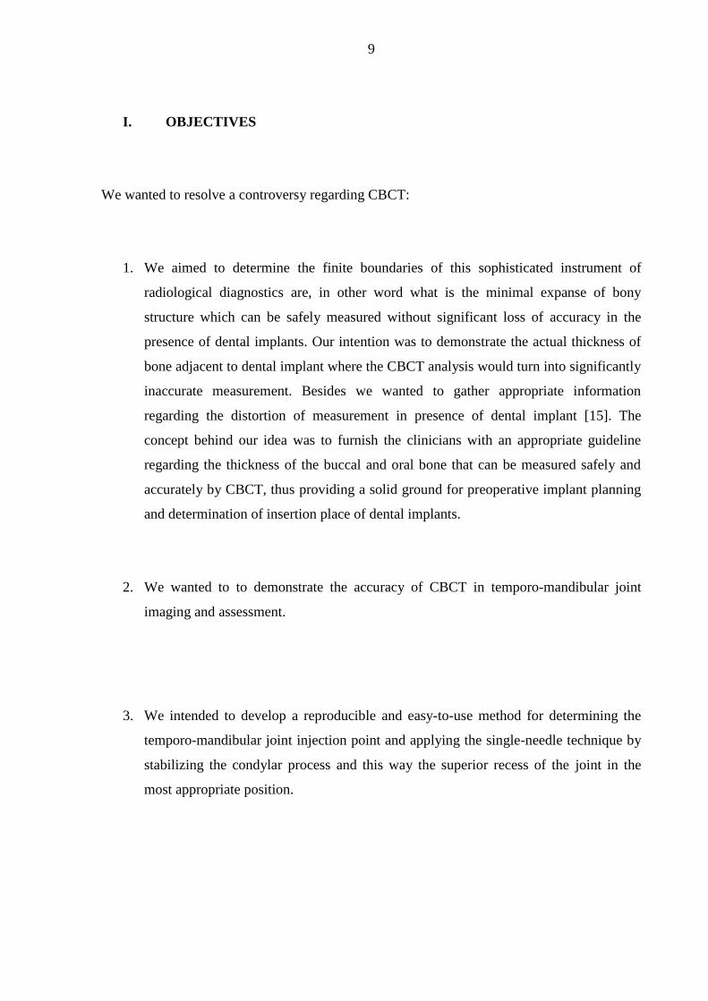
I. OBJECTIVES
We wanted to resolve a controversy regarding CBCT:
1. We aimed to determine the finite boundaries of this sophisticated instrument of
radiological diagnostics are, in other word what is the minimal expanse of bony
structure which can be safely measured without significant loss of accuracy in the
presence of dental implants. Our intention was to demonstrate the actual thickness of
bone adjacent to dental implant where the CBCT analysis would turn into significantly
inaccurate measurement. Besides we wanted to gather appropriate information
regarding the distortion of measurement in presence of dental implant [15]. The
concept behind our idea was to furnish the clinicians with an appropriate guideline
regarding the thickness of the buccal and oral bone that can be measured safely and
accurately by CBCT, thus providing a solid ground for preoperative implant planning
and determination of insertion place of dental implants.
2. We wanted to to demonstrate the accuracy of CBCT in temporo-mandibular joint
imaging and assessment.
3. We intended to develop a reproducible and easy-to-use method for determining the
temporo-mandibular joint injection point and applying the single-needle technique by
stabilizing the condylar process and this way the superior recess of the joint in the
most appropriate position.
10
II. Background
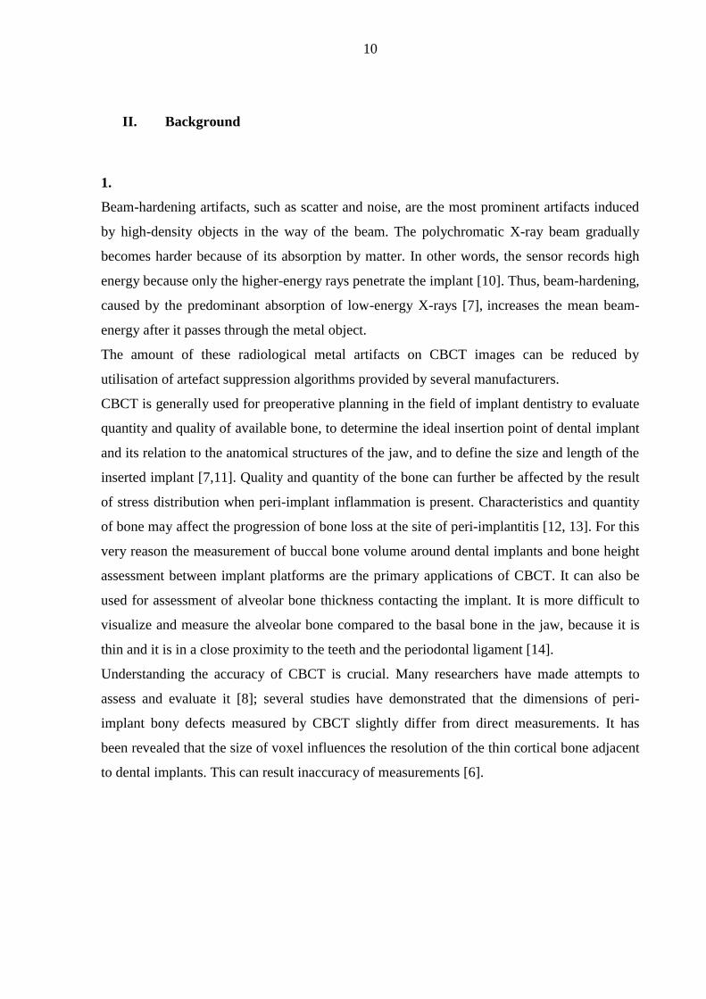
1.
Beam-hardening artifacts, such as scatter and noise, are the most prominent artifacts induced
by high-density objects in the way of the beam. The polychromatic X-ray beam gradually
becomes harder because of its absorption by matter. In other words, the sensor records high
energy because only the higher-energy rays penetrate the implant [10]. Thus, beam-hardening,
caused by the predominant absorption of low-energy X-rays [7], increases the mean beam-
energy after it passes through the metal object.
The amount of these radiological metal artifacts on CBCT images can be reduced by
utilisation of artefact suppression algorithms provided by several manufacturers.
CBCT is generally used for preoperative planning in the field of implant dentistry to evaluate
quantity and quality of available bone, to determine the ideal insertion point of dental implant
and its relation to the anatomical structures of the jaw, and to define the size and length of the
inserted implant [7,11]. Quality and quantity of the bone can further be affected by the result
of stress distribution when peri-implant inflammation is present. Characteristics and quantity
of bone may affect the progression of bone loss at the site of peri-implantitis [12, 13]. For this
very reason the measurement of buccal bone volume around dental implants and bone height
assessment between implant platforms are the primary applications of CBCT. It can also be
used for assessment of alveolar bone thickness contacting the implant. It is more difficult to
visualize and measure the alveolar bone compared to the basal bone in the jaw, because it is
thin and it is in a close proximity to the teeth and the periodontal ligament [14].
Understanding the accuracy of CBCT is crucial. Many researchers have made attempts to
assess and evaluate it [8]; several studies have demonstrated that the dimensions of peri-
implant bony defects measured by CBCT slightly differ from direct measurements. It has
been revealed that the size of voxel influences the resolution of the thin cortical bone adjacent
to dental implants. This can result inaccuracy of measurements [6].

11
2.
Temporo-mandibular joint (TMJ) pain management is one of the most difficult and
controversial treatment for physicians [26-27]. TMJ related pain is common in general
population, but only 3-7% of patients attend medical assistance [23]. Imaging of temporo-
mandibular joint and its disorders is a fundamental diagnostic step alongside physical
examination. Nonetheless physical evaluation of the temporo-mandibular joint can be
inconclusive, because the symptoms can overlap each other between internal derangement
and dysfunction resulted of myofacial pain.
The American Academy of Oral and Maxillofacial Radiology has established a baseline
protocol on selection for diagnostic, treatment planning and follow up imaging for patients
with temporo-mandibular joint disorders. This protocol comprises conventional radiographic
images such as orthopanthomogram, and TMJ tomographic sections as basic examinations
that could be adequate in most of clinical situations. Some more complicated cases – where
significant changes might occur in the bony structure and would be difficult to detect - would
require more advanced imaging technologies, such as Magnetic Resonance Imaging (MRI),
conventional Computed Tomography (CT) and Cone Beam Computed Tomography (CBCT)
[20]. The generally accepted method for proper imaging assessment is MRI, because it
provides high resolution and great contrast of the soft tissues, thus this modality is accurate to
evaluate cartilage surface of the joint, stage and position of the disc and can reveal sign of
internal derangement, arthritis or any other suspected intra-articular abnormalities [21, 22,
23].
CBCT gathered more and more ground in recent times, since it has a significant advantage to
MRI, such as this modality is specifically sensible in identification and assessment of bone
anatomy, and has the accuracy in structural analysis [20, 24]. The use of hyaluronic acid for
TMJ osteoarthritis has been proven effective [30, 31, 34, 38]. Injections of the TMJ are
inserted into the superior joint space. Guarda-Nardini et al. suggested that a single-needle
technique should be used for both the injection and the aspiration of fluid from the posterior
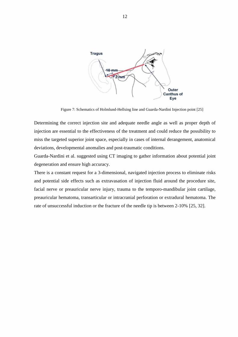
recess of the upper joint space [28-31]. The Holmlund-Hellsing line (HHL) - the line from the
lateral canthus to the most posterior and central point of the tragus - marks the needle
insertion point on the skin. The point of entry is located along the cantho-tragal line, 10 mm
from the middle of tragus and 2 mm below the cantho-tragal line (Figure 7).
12
Figure 7: Schematics of Holmlund-Hellsing line and Guarda-Nardini Injection point [25]
Determining the correct injection site and adequate needle angle as well as proper depth of
injection are essential to the effectiveness of the treatment and could reduce the possibility to
miss the targeted superior joint space, especially in cases of internal derangement, anatomical
deviations, developmental anomalies and post-traumatic conditions.
Guarda-Nardini et al. suggested using CT imaging to gather information about potential joint
degeneration and ensure high accuracy.
There is a constant request for a 3-dimensional, navigated injection process to eliminate risks
and potential side effects such as extravasation of injection fluid around the procedure site,
facial nerve or preauricular nerve injury, trauma to the temporo-mandibular joint cartilage,
preauricular hematoma, transarticular or intracranial perforation or extradural hematoma. The
rate of unsuccessful induction or the fracture of the needle tip is between 2-10% [25, 32].
13
VI. MATERIALS AND METHODS
1.
We examined the peri-implant alveolar bone quantity in a fresh domestic pig mandible, using
a young domestic pig (age: 6 months; weight: 140 kg) with healthy muscles, gingiva, and
skin. Anatomical features of the pigs are similar to human anatomy, so we used pig mandible
to assess the relationship between cortical and cancellous bone, since there is a close
similarity between pig and human mandibles regarding bone density. The domestic pig
mandible accurately represents the soft tissue cover of the alveolar bone and attenuates the
beam to soft tissue. Although the pig mandible presented tooth eruptions in the areas where
the bone quantity was sufficient for dental implantation, it is more complicated to determine
the correct implant site in edentulous human mandibles [16, 17, 18].
a) Preparation of the implant site
All implants were inserted using a full-thickness flap elevation technique with Camlog®
Surgical instruments (Camlog Biotechnologies AG, Basel, Switzerland) at the bone level, and
in some places with minimal submersion (depth: <0.5mm). The position of the implants was
determined by the bone volume, as the protocol used defined a fewer than 2 mm distance
from the implant neck on both the buccal and the oral sides. We chose the molar region where
adequate amount of bone appeared to be at disposal and there was no tooth in presence. The
flap elevation was made gently with a surgical scalpel and periosteal elevator to ensure the
correct placement and depth. A constant internal cooling procedure was used during the
implant site preparation to avoid overheating the implant-bone interface and causing any
measurement distortion.
All implant-site preparation steps were made following the CAMLOG® protocols to avoid
any distortion in implant quantity and quality.
14
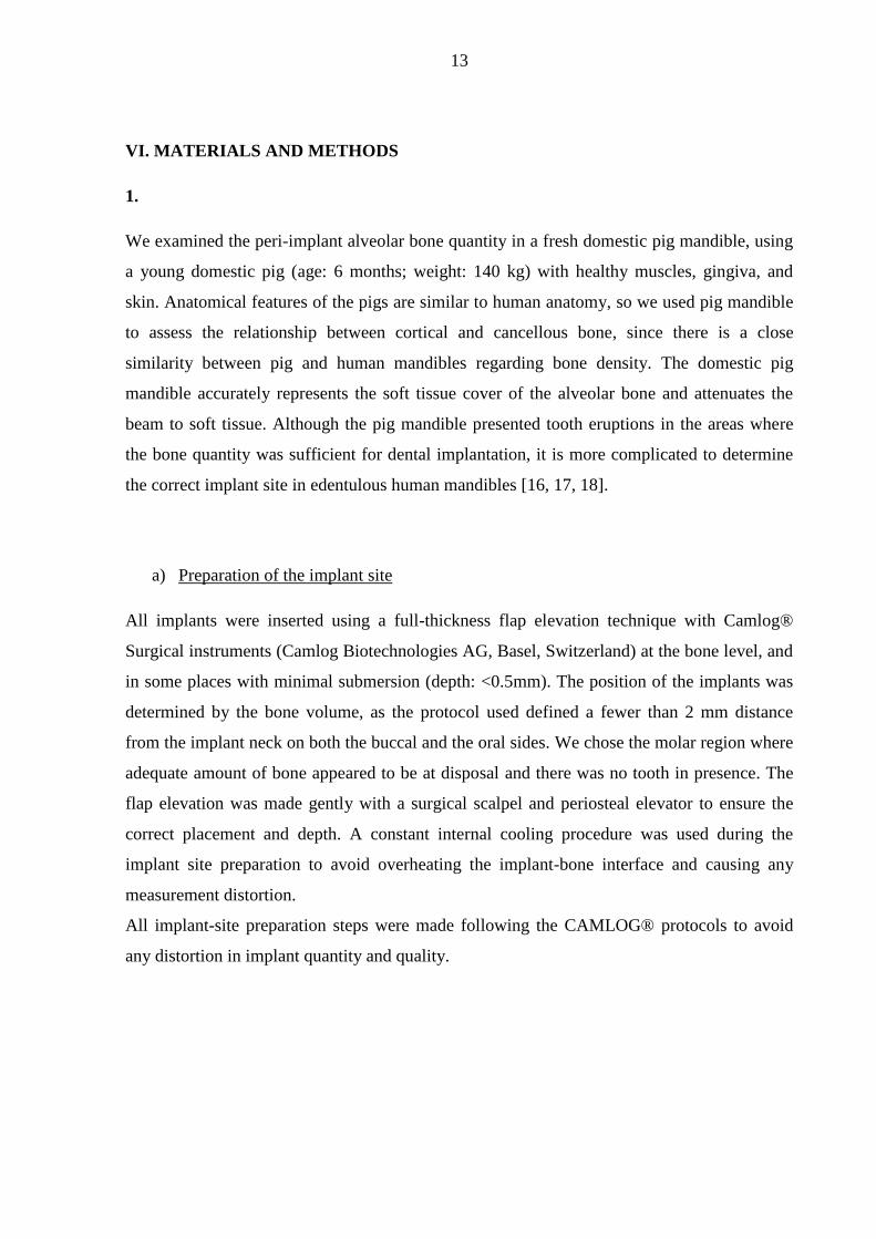
Camlog Screwline implants were used in different size in the study: 1) 4.3mm diameter,
11mm-length on the left side (implant A); 2) 3.8mm diameter, 11mm-length on the right side
(implant B); and 3) 3.8mm diameter, 13mm-length on the right side (implant C). In total, 3
implants were used (Figure 2).
Figure 2: Pig mandible with inserted implants: Left side: 4.3mm diameter, 11mm length (A); Right side: 3.8mm
diameter, 11mm length (B) and 3) 3.8mm diameter, 13mm length (C)
Three implants were placed in the molar region of the pig mandible. The implant with the
largest diameter was placed on the left side (implant A); the 2 implants placed on the right
side were slightly thinner (implants B and C) (Figure 2). The 2 neighbouring implants located
on the right side were placed more than 3 mm from each other, according to surgical
protocols.
b) Bone thinning around the implant sites
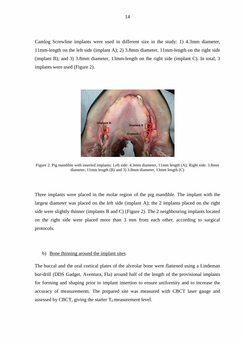
The buccal and the oral cortical plates of the alveolar bone were flattened using a Lindeman
bur-drill (DDS Gadget, Aventura, Fla) around half of the length of the provisional implants
for forming and shaping prior to implant insertion to ensure uniformity and to increase the
accuracy of measurements. The prepared site was measured with CBCT laser gauge and
assessed by CBCT, giving the starter T0 measurement level.
15
Figure 3: Cross sectional schematics of the mandible representing the flattened buccal and oral cortical side of
the alveolar process to uniform the surfaces (thick line); and schematics of gradual bone thinning process (thin
lines)
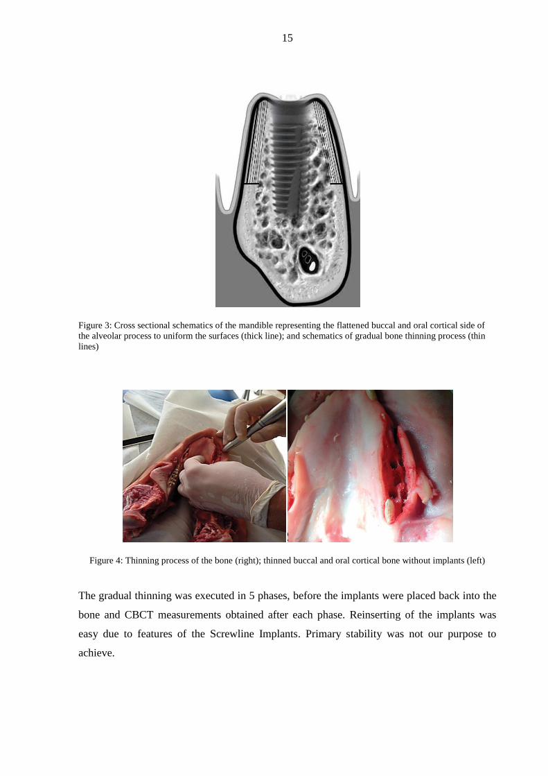
Figure 4: Thinning process of the bone (right); thinned buccal and oral cortical bone without implants (left)
The gradual thinning was executed in 5 phases, before the implants were placed back into the
bone and CBCT measurements obtained after each phase. Reinserting of the implants was
easy due to features of the Screwline Implants. Primary stability was not our purpose to
achieve.
16
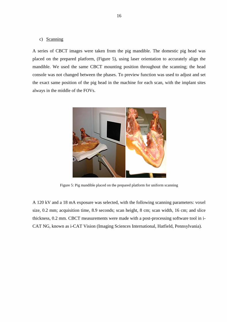
c) Scanning
A series of CBCT images were taken from the pig mandible. The domestic pig head was
placed on the prepared platform, (Figure 5), using laser orientation to accurately align the
mandible. We used the same CBCT mounting position throughout the scanning; the head
console was not changed between the phases. To preview function was used to adjust and set
the exact same position of the pig head in the machine for each scan, with the implant sites
always in the middle of the FOVs.
Figure 5: Pig mandible placed on the prepared platform for uniform scanning
A 120 kV and a 18 mA exposure was selected, with the following scanning parameters: voxel
size, 0.2 mm; acquisition time, 8.9 seconds; scan height, 8 cm; scan width, 16 cm; and slice
thickness, 0.2 mm. CBCT measurements were made with a post-processing software tool in i-
CAT NG, known as i-CAT Vision (Imaging Sciences International, Hatfield, Pennsylvania).

17
d) Measurements using the scans
All 3 implant sites were scanned and the cross-sectional images were measured with CBCT
with and without implants at each thickness level on both the buccal and the oral sides. This
assessment generated 216 measures to analyze. We used standard deviation (SD) to assess the
measure variance.
Figure 6: Coronal planes of CBCT without implant (left) and with implant (right)
2.
We designed a retrospective study to analyze radiographic data from patients undergoing TMJ
treatment in 12 cases. Ethical Approval has been obtained from Human Investigation Review
Board University of Szeged (No. 156/2018). We personally performed the injection
procedures to make sure that data analysis, targeting measurements and the procedure itself
are focused in the same hands.
a) Preparation of wax rim
Anatomical impressions were taken of upper and lower jaws the patients, and a dental
technician prepared wax rims about the instructions of the physicians to increase stability and
accuracy. The wax rims were very precise and were fitted to the occlusal surface of the teeth
to ensure that the jaws were held the same occlusal position during scanning period and at
time of injection.
18
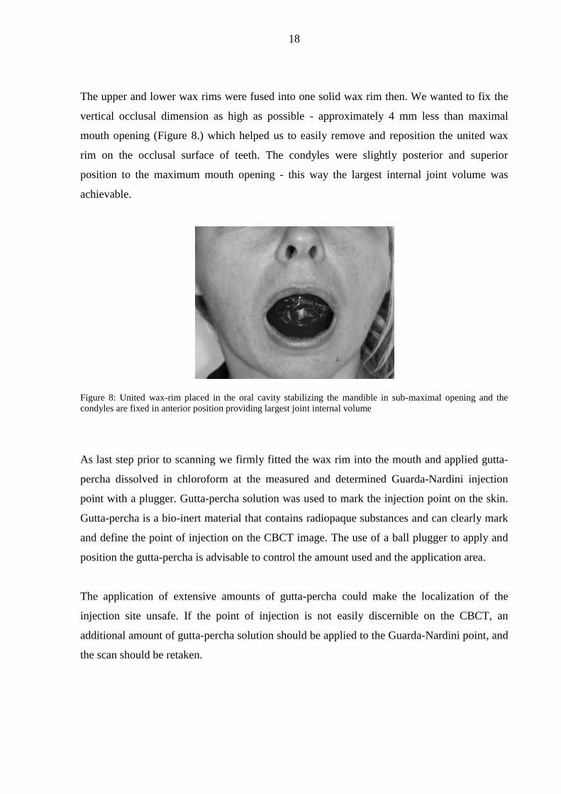
The upper and lower wax rims were fused into one solid wax rim then. We wanted to fix the
vertical occlusal dimension as high as possible - approximately 4 mm less than maximal
mouth opening (Figure 8.) which helped us to easily remove and reposition the united wax
rim on the occlusal surface of teeth. The condyles were slightly posterior and superior
position to the maximum mouth opening - this way the largest internal joint volume was
achievable.
Figure 8: United wax-rim placed in the oral cavity stabilizing the mandible in sub-maximal opening and the
condyles are fixed in anterior position providing largest joint internal volume
As last step prior to scanning we firmly fitted the wax rim into the mouth and applied gutta-
percha dissolved in chloroform at the measured and determined Guarda-Nardini injection
point with a plugger. Gutta-percha solution was used to mark the injection point on the skin.
Gutta-percha is a bio-inert material that contains radiopaque substances and can clearly mark
and define the point of injection on the CBCT image. The use of a ball plugger to apply and
position the gutta-percha is advisable to control the amount used and the application area.
The application of extensive amounts of gutta-percha could make the localization of the
injection site unsafe. If the point of injection is not easily discernible on the CBCT, an
additional amount of gutta-percha solution should be applied to the Guarda-Nardini point, and
the scan should be retaken.
19
b) Scanning
We used the following CBCT machines for the scanning: i-CAT Next Generation (Hatfield,
PA) with 17x23 FOV and Gendex GXDP 800 C (Hatfield, PA) with 8x15 FOV. 120kV and
18mA exposure was selected with the following scanning parameters: voxel size, 0.3mm;
acquisition time, 8.9 seconds; scan height, 16cm; scan width, 22cm; and slice thickness,
0.3mm. The CBCT measurements were performed using a post-processing software tool in i-
CAT NG, known as i-CAT Vision (Imaging Sciences International, Hatfield, PA).
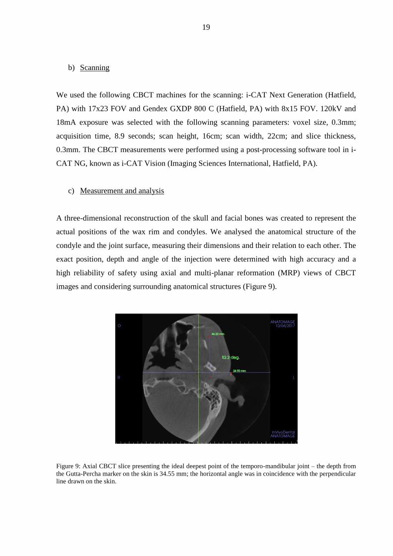
c) Measurement and analysis
A three-dimensional reconstruction of the skull and facial bones was created to represent the
actual positions of the wax rim and condyles. We analysed the anatomical structure of the
condyle and the joint surface, measuring their dimensions and their relation to each other. The
exact position, depth and angle of the injection were determined with high accuracy and a
high reliability of safety using axial and multi-planar reformation (MRP) views of CBCT
images and considering surrounding anatomical structures (Figure 9).
Figure 9: Axial CBCT slice presenting the ideal deepest point of the temporo-mandibular joint – the depth from
the Gutta-Percha marker on the skin is 34.55 mm; the horizontal angle was in coincidence with the perpendicular
line drawn on the skin.

20
It was easy to determine the exact distance from the edge of the joint to its deepest point with
MRP views; this way, accidental injuries to the joint were eliminated, and a few millimetres
of free movement range for the tip of the needle from the ideal depth of insertion could been
achieved.
Figure 10: Coronal Cone Beam CT image showing Guarda-Nardini insertion point and the measured correct
insertion point placed cranial to it. The ideal deepest measured point of the temporo-mandibular joint also
presented; depth from the marked ideal insertion point and the vertical distance as presented. The angle of the
needle insertion is 32.7 degree - calculated as the 57.3 degree measured on coronal plane to the vertical line is
deducted from 90 degree, which would be the perpendicular line to the skin. The average angle of insertion
measured was 30-35 degree
The accuracy of single-needle injection using a 3-dimensional CBCT image was analysed to
determine whether modification was necessary given the clinical anatomy of patients: the
anatomical shape and actual depth of the joint were measured on MRP views to determine the
exact distance from the edge of the joint to its deepest point (Figure 10).

21
d) The single-needle injection
The united wax rim was repositioned in the oral cavity after scanning on the occlusal surface
of the teeth to achieve the exact same position of the mandible and condyles before
performing the intra-articular injection. Besides wax rim fixed the position of the mandible, it
eliminated the function of the masticator muscles. Displacement of the jaw altogether with the
modifications of the condyle’s position and any alterations of the clinical condition of the
injection could be avoided by using this method.
The first step was to measure maximum mouth opening of the patient and measure how much
the acrylic base of the wax rim extended over the teeth. The average overflow of the plates
was 1.8mm in buccal and 2.2mm orally, so in total 4mm, so the wax rim was prepared an
approximately 4mm sub-maximal open position to ensure easy removal.
Patient was questioned about medical history and any allergies. Informed consent was taken.
After sterile standard preparation and draping, the Guarda-Nardini point was marked on the
skin with a removable, sterile skin marker – on the same spot as with gutta-percha prior to
scans. The needle was inserted at the allocated insertion point – which was correlated to the
Guarda-Nardini point - at the precise angle and depth that was previously determined on the
3-dimensional CBCT images with the wax rim in situ (Figure 11).
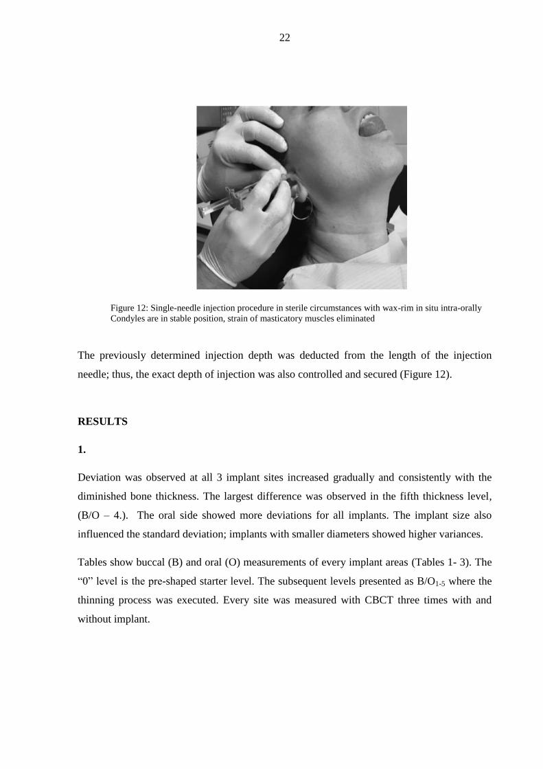
The procedure took several minutes to perform under sterile circumstances. The patients were
seated in a dental chair in a relaxed position.
Figure 11: Gutta-Percha markers on skin surface present predetermined Guarda-Nardini (GN) point and
measured – correct – insertion point; misguided injection could be avoided with accurate analysis
22
Figure 12: Single-needle injection procedure in sterile circumstances with wax-rim in situ intra-orally
Condyles are in stable position, strain of masticatory muscles eliminated
The previously determined injection depth was deducted from the length of the injection
needle; thus, the exact depth of injection was also controlled and secured (Figure 12).
RESULTS
1.
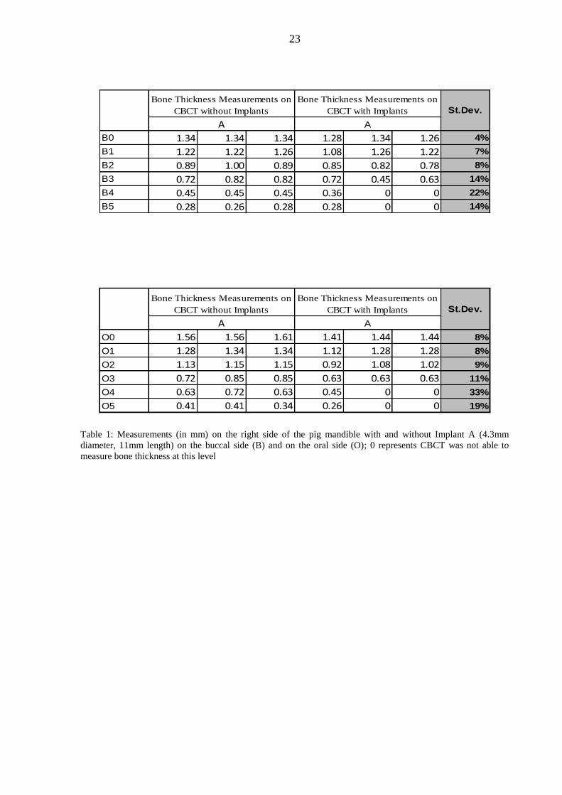
Deviation was observed at all 3 implant sites increased gradually and consistently with the
diminished bone thickness. The largest difference was observed in the fifth thickness level,
(B/O – 4.). The oral side showed more deviations for all implants. The implant size also
influenced the standard deviation; implants with smaller diameters showed higher variances.
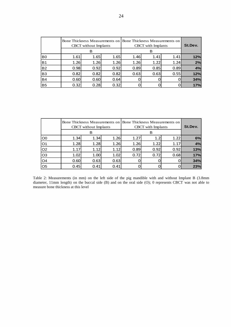
Tables show buccal (B) and oral (O) measurements of every implant areas (Tables 1- 3). The
“0” level is the pre-shaped starter level. The subsequent levels presented as B/O1-5 where the
thinning process was executed. Every site was measured with CBCT three times with and
without implant.
23
B0 1.34 1.34 1.34 1.28 1.34 1.26 4%
B1 1.22 1.22 1.26 1.08 1.26 1.22 7%
B2 0.89 1.00 0.89 0.85 0.82 0.78 8%
B3 0.72 0.82 0.82 0.72 0.45 0.63 14%
B4 0.45 0.45 0.45 0.36 0 0 22%
B5 0.28 0.26 0.28 0.28 0 0 14%
Bone Thickness Measurements on
CBCT without Implants
Bone Thickness Measurements on
CBCT with Implants St.Dev.
A A
O0 1.56 1.56 1.61 1.41 1.44 1.44 8%
O1 1.28 1.34 1.34 1.12 1.28 1.28 8%
O2 1.13 1.15 1.15 0.92 1.08 1.02 9%
O3 0.72 0.85 0.85 0.63 0.63 0.63 11%
O4 0.63 0.72 0.63 0.45 0 0 33%
O5 0.41 0.41 0.34 0.26 0 0 19%
Bone Thickness Measurements on
CBCT with Implants St.Dev.
A A
Bone Thickness Measurements on
CBCT without Implants
Table 1: Measurements (in mm) on the right side of the pig mandible with and without Implant A (4.3mm
diameter, 11mm length) on the buccal side (B) and on the oral side (O); 0 represents CBCT was not able to
measure bone thickness at this level
24
B0 1.61 1.65 1.65 1.46 1.41 1.41 12%
B1 1.26 1.26 1.26 1.26 1.22 1.24 2%
B2 0.98 0.92 0.92 0.89 0.85 0.89 4%
B3 0.82 0.82 0.82 0.63 0.63 0.55 12%
B4 0.60 0.60 0.64 0 0 0 34%
B5 0.32 0.28 0.32 0 0 0 17%
Bone Thickness Measurements on
CBCT without Implants
Bone Thickness Measurements on
CBCT with Implants St.Dev.
B B
O0 1.34 1.34 1.26 1.27 1.2 1.22 6%
O1 1.28 1.28 1.26 1.26 1.22 1.17 4%
O2 1.17 1.12 1.12 0.89 0.92 0.92 13%
O3 1.02 1.00 1.02 0.72 0.72 0.68 17%
O4 0.60 0.63 0.63 0 0 0 34%
O5 0.45 0.41 0.41 0 0 0 23%
Bone Thickness Measurements on
CBCT with Implants St.Dev.
B B
Bone Thickness Measurements on
CBCT without Implants
Table 2: Measurements (in mm) on the left side of the pig mandible with and without Implant B (3.8mm
diameter, 11mm length) on the buccal side (B) and on the oral side (O); 0 represents CBCT was not able to
measure bone thickness at this level

25
B0 1.22 1.26 1.28 1.17 1.22 1.22 4%
B1 1 1.08 1.08 1.02 1 1.04 4%
B2 0.82 0.85 0.85 0.82 0.84 0.84 1%
B3 0.72 0.68 0.72 0.45 0.45 0.41 15%
B4 0.32 0.32 0.36 0 0 0 18%
B5 0.28 0.28 0.28 0 0 0 15%
Bone Thickness Measurements on
CBCT without Implants
Bone Thickness Measurements on
CBCT with Implants St.Dev.
C C
O0 1.41 1.40 1.41 1.46 1.41 1.46 3%
O1 1.12 1.14 1.12 1.08 1.06 1.06 3%
O2 0.89 0.89 0.92 0.89 0.85 0.85 3%
O3 0.63 0.58 0.63 0.52 0.45 0.45 8%
O4 0.45 0.35 0.45 0 0 0 23%
O5 0.28 0.26 0.26 0 0 0 15%
Bone Thickness Measurements on
CBCT with Implants St.Dev.
C C
Bone Thickness Measurements on
CBCT without Implants
Table 3: Measurements (in mm) on the right side of the pig mandible with and without Implant C (3.8mm
diameter, 13mm length) on the buccal side (B) and on the oral side (O); 0 represents CBCT was not able to
measure bone thickness at this level
Note: The standard deviation is a statistic that measures the dispersion of a dataset relative to its mean and is
calculated as the square root of the variance. It is calculated as the square root of variance by determining the
variation between each data point relative to the mean. If the data points are further from the mean, there is a
higher deviation within the data set; thus, the more spread out the data, the higher the standard deviation. Conversely, a higher standard deviation indicates a wider range of values.
26
2.
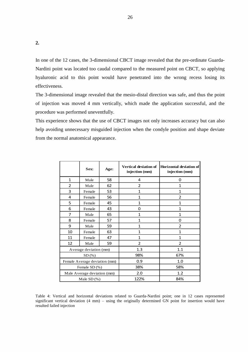
In one of the 12 cases, the 3-dimensional CBCT image revealed that the pre-ordinate Guarda-
Nardini point was located too caudal compared to the measured point on CBCT, so applying
hyaluronic acid to this point would have penetrated into the wrong recess losing its
effectiveness.
The 3-dimensional image revealed that the mesio-distal direction was safe, and thus the point
of injection was moved 4 mm vertically, which made the application successful, and the
procedure was performed uneventfully.
This experience shows that the use of CBCT images not only increases accuracy but can also
help avoiding unnecessary misguided injection when the condyle position and shape deviate
from the normal anatomical appearance.
Sex: Age:Vertical deviation of
injection (mm)
Horizontal deviation of
injection (mm)
1 Male 58 4 0
2 Male 62 2 1
3 Female 53 1 1
4 Female 56 1 2
5 Female 45 1 1
6 Female 43 0 1
7 Male 65 1 1
8 Female 57 1 0
9 Male 59 1 2
10 Female 63 1 1
11 Female 47 1 1
12 Male 59 2 2
1.3 1.1
98% 67%
0.9 1.0
38% 58%
2.0 1.2
122% 84%Male SD (%)
Average deviation (mm)
SD (%)
Female Average deviation (mm)
Female SD (%)
Male Average deviation (mm)
Table 4: Vertical and horizontal deviations related to Guarda-Nardini point; one in 12 cases represented
significant vertical deviation (4 mm) – using the originally determined GN point for insertion would have
resulted failed injection
27
In all 12 cases we experienced various degree of deviation from the pre-ordinate Guarda-
Nardini-point either horizontally, vertically or in depth especially in case of patients with
anatomical anomalies (Table 4). Despite small inconvenience caused by the insertion of
needle, patients did not experience additional pain, as the tip of the needle did not reach the
cartilage or periosteum causing injury to these layers.
Quick and satisfactory relief has been achieved from injection without complications; they
felt only mild discomfort around the injection site that originated from the extra volume in the
joint and resolved a few hours after the procedure. The physicians had a high degree of
certainty regarding where to apply the injection: the exact point, depth and angle.
Furthermore, the wax rim fixed the maxilla and mandible, thereby eliminating the risk of
displacement caused by reflexive muscle contraction. The patients began active exercises to
move their TMJ the day after the procedure.
VIII. DISCUSSION
The success of a dental implantation depends on adequate volume and quality of bone,
frequently evaluated using 3-dimensional (3D) visualization.
Thinning of the bone was found to influence the diagnostic accuracy of CBCT. With thinner
bones, the implant site is an air-containing space that leads to over-radiation of the buccal and
oral cortical bones. This excess radiation makes the scanned image darker, and the
measurements smaller.
When X-ray photons pass through the dental implant, the lower-energy photons are
preferentially absorbed. This affects bone and soft tissue visualization and results in
inaccurate assessment of peri-implant regions. The cupping artifact can occur when the X-
rays passing through the centre of the dental implant become harder than those passing
through the edges, causing an attenuation effect appearing as a "cup", also dark streak and
band artifacts to appear between 2 dental implants. Furthermore, the large flat panel detector
increases the scatter radiation, and thus limits the soft tissue boundaries.
28
Higher spatial resolution in CBCT images results higher diagnostic accuracy, because actual
cross-sectional images use isotropic voxel size. Additionally, higher applied voltage can
reduce the contrast in CBCT images.
Our data show that thinner bone results in greater discrepancy between the measurements
with and without implants, and that these differences are driven by beam-hardening artifacts,
which cause gray-level reduction both buccally and orally. Only the thinnest level showed
differences, and the iCAT software could not handle the small anatomical details. Thus, there
were inaccuracies in defining the border of the thin bone wall.
The presence of 2 neighbouring implants also affected the evaluation of peri-implant bone
quality negatively because of the appearance of the beam hardening artifacts in between two
implants. The purpose of using thicker implants was to understand how their thickness
influenced the evaluation of peri-implant bone volume and quality using CBCT, particularly
at the edge of the alveolar process. We found that the size of the implants did not affect the
evaluation of bone quantity.
The purpose of thinning the bone was to determine how beam-hardening artifacts caused by
the presence of the implants influenced bone thickness evaluation. We determined that
thinning of the alveolar bone around the implant site reduces the diagnostic accuracy of
CBCT. Further, a thicker alveolar bone (0.72–1.6mm) around the dental implant causes the
CBCT to underestimate bone volume by approximately 10%, while rate of the
underestimation for a thinner alveolar bone (< 0.72mm) is approximately 70%. This is a
significant finding considering about 0.9 mm difference in bone thickness can result in 60%
inaccuracy.
We determined that CBCT has limitation of accuracy due to peri-implant bone thinning.
These new findings reflect a different light on pre-implantation planning procedure, since we
could demonstrate the level of underestimation of CBCT can be significantly high in case of
thinner buccal bone, hence clinicians have to consider choosing proper site for implantation
after careful assessment of bone thickness. This way we can declare that the safe thickness of
buccal and oral bone at the site of desired implantation should be at least 1.5mm, thus the
chance of bone underestimation by CBCT can be reduced to less than 10%.
29
After we could demonstrate the measurement accuracy of CBCT between 0.5 and 1.5mm
bone thickness, we wanted emphasize its high reliability in the field of TMJ analysis and its
future place in the field of diagnostics and therapy planning of temporo-mandibular joint
disorders since the size of the superior recess of the joint is greater than 1.5mm. Application
of CBCT imaging and analysis gave us a lead to describe a method of TMJ injection with
great safety considering that the treatment of TMJ disorders are always a challenging task for
physicians, and the techniques [33-34] and medications [26-27] used to address patients’
symptoms still remain a matter of dispute.
The glenoid fossa is thin, ranging in thickness from of 0.5 to 1.5mm, and the cartilaginous
surface may be eroded by degenerative arthritis or previous infections; these factors may
present such an anatomical condition that can result in potential further damage during the
injection.
Mouth opening motions displace the condylar processes in mesial and caudal direction,
creating a triangle-shaped depression in front of the tragus on the skin, which makes
identification easier. In cases of severe degenerative lesions with “closed lock”, limited
translation may occur that results in a more pronounced triangular demarcation and a
complicated injection. The use of this method may help to control the injection of hyaluronic
acid or other materials into the temporo-mandibular joint with severe degenerative lesion.
The wax rims are attached to each other under clinical conditions in a position near the
maximum mouth opening, and the united wax rims should be removable and repositionable
during scanning or injection. It is very important that the united upper and lower wax rims are
stable and rigid for very precise positioning in the mouth.
The developed method has many advantages:
i) The procedure causes minimal trauma to the joint as the risk of intra-articular
injury is reduced to a very low level
ii) Postoperative discomfort is tolerable as the extra intra-articular volume dissolves
in a short time
iii) Additional local anaesthetic is not required as a single insertion is needed.
30
IX. CONCLUSION
1. We could demonstrate and prove limitations of CBCT in accuracy of bone thickness
measurement. This is a relevant finding hence we could determine the level of bone
thickness where CBCT images can reach the point of significant underestimation. We
could prove that presence of a dental implant has an influence on bone thickness
evaluation in particular if there is more than one implant placed in the bone in vicinity
to each other. This can provide a definite base to dentists, dento-alveolar and
maxillofacial surgeons in their service of implantation in consideration of careful
choosing the site of the planned implant. Since adequate volume of healthy bone is
crucial for successful implant outcome, we are certain that this new information will
be beneficial for providers and patients alike.
2. After we presented limitations of CBCT accuracy and have been aware of bone
thickness level were the underestimation was significant, we have been certain that
CBCT could be expedient in assessment and treatment of temporo-mandibular joint,
as the dimensions of the joint are beyond the underestimation level. We could analyse
the anatomical structures of the temporo-mandibular joint utilizing CBCT features.
3. We developed a new safe, reproducible technique for single-needle TMJ injection
with application of Cone Beam CT targeting method which is unique as no similar has
been published till now in the literature.
4. We could determine the position of the injection point related to the pre-determined
Guarda-Nardini-point, and the exact depth and direction of the injecting needle. The
described technique could make single-needle injection easier to perform as
difficulties resulting from the deviated anatomy can be eliminated and individual
values can be defined for the injection.

31
5. The method is reproducible, as all images and data can be stored, re-evaluated and
compared with later stages. The individually fabricated wax-rim can also be stored,
thus by repositioning it into the given patient’s mouth the condyles can be stabilized in
the exact same position for subsequent CBCT assessment and single-needle injection
if necessary. This way easier follow-up of the affected TMJ can be reached as CBCT
does not require a large radiation load. This method can be helpful in the treatment of
TMJ disorders, making the approach simpler, easier and more comfortable for patients
and physicians. We intend to further develop and refine our method in the future with
addition of a more sophisticated targeting system. Our method can be the foundation
for a constantly requested three-dimensional, navigated injection process.
32
X. Acknowledgement
First of all I would like to express my gratitude to my supervisor, The Dean of Dental Faculty,
Dr. Zoltán Baráth, who stood on my side with unbreakable faith and helped me on this road.
Our relationship is beyond professional boundaries; our similar path of life and congenial
approach to essential and fundamental matters of life founded a friendship far before this
project has been started.
Special thanks to Professor Márta Radnai for her careful reading, comments and useful
advises.
I would like thank to Professor Ádám Kovács, who invited me to the specialty of Oral- and
Maxillofacial Surgery and started my training in this beautiful profession showing me finesses
as a good mentor does. His persistent friendship means a lot.
I am grateful to Professor Katalin Nagy, who paved my way when I found myself in a strange
new world after being a Trauma Surgeon, and to date I can respectfully consider her a good
friend.
Let me express my appreciation to Professor József Piffkó, who made possible with his
tireless work for the Oral- and Maxillofacial Surgery specialty to survive and live on and then
flourish in Hungary, and enabled for me to be the surgeon I am today.
I want to thank to all my Colleagues, Doctors, Nurses, Assistants, Theatre Nurses, Porters,
my Patients and my Friends for being around me, helping and accepting me…sometimes it
has not been easy.
I would like to thank to my Parents for bringing me up. You’ve always been and are on my
side. I would like to dedicate this work to my Father, who armored me with wise realizations
and has always been optimistic of my professional advancement. I will always be thankful to
my Mother for her temper, attitude and strong personality that formed me the man I am
today.
Last, but not least let me express my deepest gratitude to my Best Friend and Love of my Life,
my Wife Melinda, who is always there for me in better or worse and supports me whenever
she feels I am in need of help. I am also thankful to my Children, who gave me the chance to
know what it means to be a Father.

33
XI. REFERENCES
[1] Thunthy K H: Timeline of Oral and Maxillofacial Radiology
[2] Hallikainen D: History of panoramic radiography.
Acta Radiol 1996; 37(3 Pt 2): 441-445.
[3] Scarfe WC, Farman AG: What is Cone-Beam CT and How Does it Work?
Dent Clin N Am (52) 2008: 707-730.
[4] Scarfe WC, Farman AG, Sukovic P: Clinical Applications of Cone-Beam Computed
Tomography in Dental Practice
J Can Dent Assoc 2006; 72(1): 75-80.
[5] Venkatesh E, Venkatesh S Elluru: Cone beam computed tomography: basics and
applications in dentistry
J Istanb Univ Fac Dent. 2017; 51(3 Suppl 1): 102-121.
[6] Razavi T, Palmer R M, Davies J, Wilson R, Palmer P J: Accuracy of measuring the
cortical bone thickness adjacent to dental implants using cone beam computed tomography.
Clin Oral Implants Res; 2010; 21: 718-725.
[7] Pauwels R, Stamatakis H, Bosmans H, et al.: Quantification of metal artifacts on cone
beam computed tomography images.
Clin Oral Implants Res; 2013; 24 (suppl A100): 94-99.
[8] Patcas R, Müller L, Ullrich O, Peltomäki T: Accuracy of cone-beam computed
tomography at different resolutions assessed on the bony covering of the mandibular anterior
teeth.
Am J Orthod Dentofac Orthop; 2012; 141: 41-50.
[9] Molen AD: Considerations in the use of cone-beam computed tomography for buccal bone
measurements.
Am J Orthod Dentofac Orthop; 2010; 137(4 suppl): 130-135.
[10] Schulze R K, Berndt D, d'Hoedt B: On cone-beam computed tomography artifacts
induced by titanium implants.
Clin Oral Implants Res; 2010; 21: 100-107.
[11] Hassan, B, Jacobs, R: Cone beam computed tomography–3D imaging in oral and
maxillofacial surgery
Eur Med Imaging Rev; 2008; 1: 38-40.
34
[12] Alikhasi M, Siadat H, Geramy A, Hassan-Ahangari A: Stress distribution around
maxillary anterior implants as a factor of labial bone thickness and occlusal load angles: a 3-
dimensional finite element analysis.
J Oral Implantol 2014; 40: 37-41.
[13] Serino G, Turri A: Extent and location of bone loss at dental implants in patients with
peri-implantitis.
J Biomech 2011; 44: 267-271.
[14] Brief J, Edinger D, Hassfeld S, Eggers G: Accuracy of image-guided implantology.
Clin Oral Implants Res; 2005; 16(4): 495-501.
[15] Wood R, Sun Z, Chaudhry J, et al.: Factors affecting the accuracy of buccal alveolar
bone height measurements from cone-beam computed tomography images.
Am J Orthod Dentofac Orthop; 2013; 143(3): 353-363.
[16] Štembírek J, Kyllar M, Putnová I, Stehlík L, Buchtová M.: The pig as an experimental
model for clinical craniofacial research.
Lab Anim; 2012; 46: 269-279.
[17] Zangrando M S R, Sant’Ana ACP, Greghi SLA, de Rezende M L R, Damante C A: Pig
mandible as a valuable tool to improve periodontal surgery techniques.
Int Educ Stud; 2014; 7: 82-88.
[18] Mengel R, Kruse B, Flores-de-Jacoby L: Digital volume tomography in the diagnosis of
peri-implant defects: an in vitro study on native pig mandibles.
J Periodontol 2006; 77: 1234-1241.
[19] Wenzel A, Haiter-Neto F, Frydenberg M, Kirkevang L L: Variable-resolution cone-beam
computerized tomography with enhancement filtration compared with intraoral
photostimulable phosphor radiography in detection of transverse root fractures in an in vitro
model.
Oral Surg Oral Med Oral Pathol Oral Radiol Endod; 2009; 108: 939-945.
[20] Krishnamoorthy B, Mamatha N S, Kumar V A R: TMJ imaging by CBCT: Current
scenario
Ann Maxillofac Surg; 2013; 3(1): 80–83.
[21] Wang EY, Fleisher K A: MRI of temporomandibular joint disorders
Applied Radiology 2008 37(9): 17-25.
[22] Larheim: Role of magnetic resonance imaging in the clinical diagnosis of the
temporomandibular joint.
Cells Tissues Organs 2005; 180(1): 6-21.
35
[23] Bag A K, Gaddikeri S, Singhal A, Hardin S, Tran B D, Medina J A, Curé J K:
Imaging of the temporomandibular joint: An update
World J Radiol 2014; 6(8): 567–582.
[24] Larheim T A, Abrahamsson A-K,
Kristensen M,
Arvidsson L Z: Temporomandibular
joint diagnostics using CBCT
Dentomaxillofac Radiol 2015; 44(1): 20140235
[25] Pumklin J: A literature review of temporomandibular joint arthrocentesis: start to success
J Int Dent Med Res 2018; 11(2): 486-490
[26] Kopp S, Wenneberg B, Haraldson T, et al.: The short-term effect of intra-articular
injections of sodium hyaluronate and corticosteroid on temporomandibular joint pain and
dysfunction
J Oral Maxillofac Surg; 1985; 43(6): 429-435.
[27] Kopp S, Carlsson G E, Haraldson T, et al.: Long-term effect of intra-articular injections
of sodium hyaluronate and corticosteroid on temporomandibular joint arthritis
J Oral Maxillofac Surg; 1987; 45(11): 929-935.
[28] Machado E, Bonotto D, Cunali P A: Intra-articular injections with corticosteroids and
sodium hyaluronate for treating temporomandibular joint disorders: a systematic review
Dental Press J Orthod; 2013; 18(5): 128-133.
[29] Guarda-Nardini L, Ferronato G, Favero L, et al.: Predictive factors of hyaluronic acid
injections short-term effectiveness for TMJ degenerative joint disease.
J Oral Rehabil; 2011; 38(5): 315-320.
[30] Manfredini D, Piccotti F, Guarda-Nardini L.: Hyaluronic acid in the treatment of TMJ
disorders: a systematic review of the literature.
CRANIO® The J Craniomand & Sleep Pract; 2010; 28(3): 166-176.
[31] Basterzi Y, Sari A, Demirkan F, et al.: Intra-articular hyaluronic-acid injection for the
treatment of reducing and non-reducing disc-displacement of the temporo-mandibular joint
Ann Plast Surg; 2009; 62(3): 265-267.
[32] Guarda-Nardini L, Cadorin C, Frizziero A, et al.: Interrelationship between temporo-
mandibular joint osteoarthritis (OA) and cervical spine pain: Effects of intra-articular
injection with hyaluronic acid.
CRANIO® The J Craniomand & Sleep Pract; 2016; 35(5): 276-282.
[33] Torres D E, McCain J P.: Arthroscopic electrothermal capsulorrhaphy for the treatment
of recurrent temporomandibular joint dislocation
Int J Oral and Maxillofac Surg; 2012; 41: 681-689.
36
[34] Long X, Chen G, Cheng A H, et al.: A randomized controlled trial of superior and
inferior temporomandibular joint space injection with hyaluronic acid in treatment of anterior
disc displacement without reduction.
J Oral Maxillofac Surg; 2009; 67(2): 357-361.
[35] Cascone P, Fonzi, Dagger L, Aboh V.: Hyaluronic acid's biomechanical stabilization
function in the temporomandibular joint
J Craniofac Surg; 2002;13(6): 751-754.
[36] Yavuz I, Rizal M F, Kiswanjaya B: The Possible Usability of Three-dimensional Cone
Beam Computed Dental Tomography in Dental Research
J Physics: Conf. Series 884; (2017) 012041: 1-21.
[37] Kailash S: CBCT – Cone Beam Computed Tomography
J Acad Dent Educ; Vol: 1 2014: 9-15.
[38] Triantaffilidou K, Venetis G, Bika O: Efficacy of hyaluronic acid injections in patients
with osteoarthritis of the temporomandibular joint. A comparative study
J Craniofac Surg; 2013; 24(6): 2006-2009.
[39] Govila S, Gundappa M: Cone beam computed tomography - an overview
J Cons Dent; 2007 Vol. 10 Issue 2: 53-58.