cloud-tm - distributed systems groupromanop/files/deliverables/d2_1.pdf · 1.1 relationship with...
TRANSCRIPT

Cloud-TMSpecific Targeted Research Project (STReP)
Contract no. 257784
D2.1: Architecture Draft
Date of preparation: 10 June 2011Start date of project: 1 June 2010Duration: 36 Months

Contributors
Emmanuel Bernard, Red HatJoao Cachopo, INESC-IDBruno Ciciani, CINIDiego Didona, INESC-IDFrancesca Giannone, ALGORITHMICAMark Little, Red HatSebastiano Peluso, INESC-IDFrancesco Quaglia, CINILuis Rodrigues, INESC-IDPaolo Romano, INESC-IDVittorio A. Ziparo, ALGORITHMICA
——————————————————(C) 2010 Cloud-TM Consortium. Some rights reserved.
This work is licensed under the Attribution-NonCommercial-NoDerivs 3.0 CreativeCommons License. See http://creativecommons.org/licenses/by-nc-nd/3.0/legalcode
for details.

Table of Contents1 Introduction 4
1.1 Relationship with other deliverables . . . . . . . . . . . . . . . . . . 4
2 Architectural overview 5
3 Data Platform 73.1 Generic Tunable Component Interfaces . . . . . . . . . . . . . . . . 83.2 Data Platform APIs . . . . . . . . . . . . . . . . . . . . . . . . . . . 15
3.2.1 Object grid mapper . . . . . . . . . . . . . . . . . . . . . . . 173.2.1.1 Two different APIs for the Object Grid Mapper . . 173.2.1.2 Hibernate Object Grid Mapper . . . . . . . . . . . 18
How is data persisted . . . . . . . . . . . . . . . . . . 203.2.1.3 Fénix Framework Object Grid Mapper . . . . . . . 23
Classes layout . . . . . . . . . . . . . . . . . . . . . 24Mapping objects to Infinispan . . . . . . . . . . . . . 25Direct mapping to Infinispan . . . . . . . . . . . . . . 25
3.2.2 Search APIs . . . . . . . . . . . . . . . . . . . . . . . . . . 263.2.3 Distributed Execution Framework . . . . . . . . . . . . . . . 35
3.2.3.1 Distributed Execution Model . . . . . . . . . . . . 363.2.3.2 Map Reduce Execution Model . . . . . . . . . . . 38
3.3 Reconfigurable Software Transactional Memory . . . . . . . . . . . . 403.3.1 Infinispan’s main operational modes . . . . . . . . . . . . . 403.3.2 High level architecture . . . . . . . . . . . . . . . . . . . . . 42
Core Modules . . . . . . . . . . . . . . . . . . . . . . 42Additional modules involved in full replication mode . 44Additional modules involved in partial replication mode 44
3.3.3 Extensions to support complex dynamic reconfigurations . . 453.4 Reconfigurable storage system . . . . . . . . . . . . . . . . . . . . . 49
3.4.1 Interfaces towards Persistent Storages . . . . . . . . . . . . . 49Eviction and passivation . . . . . . . . . . . . . . . . 51
3.4.2 Run-time reconfiguration support . . . . . . . . . . . . . . . 53
4 Autonomic Manager 544.1 QoS API . . . . . . . . . . . . . . . . . . . . . . . . . . . . . . . . 554.2 Workload and Performance Monitor . . . . . . . . . . . . . . . . . . 574.3 Workload Analyzer . . . . . . . . . . . . . . . . . . . . . . . . . . . 624.4 Adaptation Manager . . . . . . . . . . . . . . . . . . . . . . . . . . 66
References 71
A XML Schema for file descriptors of Generic Tunable Components 72
3

1 IntroductionThis deliverable is the result of the activities carried out by the project’s partners in thecontext of WP2 (Task 2.1) and WP3 (Task 3.1), and describes the planned architectureof the Cloud-TM platform.
More in detail, the goal of this deliverable is twofold:
• defining the platform’s architecture, describing relations and data flows amongthe various modules of the system, as well as the internal design of the maincomponents of the Cloud-TM platform;
• specifying, whenever this is already possible, the external interfaces among themain components of the Cloud-TM platform, in order to decouple them andallow parallel development by the various members of the Cloud-TM project’steam.
It is important to clarify that the design decisions discussed in this deliverable arenot meant as conclusive and inalterable. Conversely, they represent a commonly agreedstarting point, which summarizes the results of the design activities performed duringthe first year of the project, and which will need to be validated (and possibly be subjectto changes) while progressing with the research and development work carried outduring the future phases of the project.
1.1 Relationship with other deliverablesThe architecture defined in this deliverable has been developed on the basis of the userrequirements gathered in the deliverable D1.1 “User Requirements Report”, and takinginto account the technologies identified in the deliverable D1.2 “Enabling TechnologiesReport”.
This deliverable has also a relation with the deliverable D2.2 “Preliminary Proto-type of the RDSTM and the RSS”, which includes a preliminary (non self-tunable)version of the components of the Cloud-TM Data Platform, whose architecture is de-scribed in the following.
Also, section 4.2, which describes the architecture of the Workload Monitor, isclearly related to the deliverable D3.2 “Prototype of the Workload Monitor”.
Finally, the architecture defined hereafter will serve as a reference to guide thedevelopment of the deliverables associated with the prototypes of the Cloud-TM plat-form, namely the deliverables D2.3 “Prototype of the RDSTM and of the RSS”, D3.2“Prototype of the Workload Analyzer”, D3.4 “Prototype of the Autonomic Manager”,and, finally, D4.5 “Final Cloud-TM Prototype”.
4

2 Architectural overview
!""#$%&'()*+&,-.$
/0/%1/1!23$4
/3/567$
7+8'9:;<&"=>+$0)-?&)=<?+*$
#'@A"&+$1&"9-"8B'9">$4+C'&D$
7+8'9:;<&"=>+$#?'&";+$#D-?+C$
0"?"$%>"E'&C$%&';&"CC)9;$/%!-$
F27GH2
/0$I$J'#$4
23!127$
F27GH2
/0$/3/HKL67$
!"#$%$&'()*+%+,-.)/+#+)01+2$.&)
J'#M8'-?$-N+8):8"B'9$/%!$
31$"456*)01+2$.&)
6>"-B8$#
8">)9;$
4"9";+&$
.-7$".(-)
8.$9'7'$%'%,):)
;<!)%-,$=+=$%)
2=O+8?$5&)*$
4"NN+&$#+"&8P$/%!$
0)-?&)=<?+*$
6Q+8<B'9$
R&"C+A'&S$
/+#+)01+2$.&)>-($%?,".+=$%)@)6"%'%,)
0"?"$%>"E'&C
$
2NBC)T+
&$
Figure 1: Architectural Overview of the Cloud-TM Platform.
Figure 1 presents the high level architecture diagram of the Cloud-TM platform.This will be used as a starting point to derive, in a top down fashion, more refinedversions of the platform's main building blocks, which will be described in detail in theremainder of this document.
This diagram represents a refinement of the architectural diagram shown in Figure 1of Annex I - “Description of Work”, which has been updated to incorporate the resultsachieved so far in the project.
As already discussed in deliverable D1.1 “User requirements”, the Cloud-TM plat-form will be formed by two main parts: the Data Platform and the Autonomic Manager.
The Data Platform will be responsible for storing, retrieving and manipulating dataacross a dynamic set of distributed nodes, elastically acquired from the underlying IaaSCloud provider(s). It will expose a set of APIs, denoted as “Data Platform Program-ming APIs” in Figure 1, aimed at increasing the productivity of Cloud programmersfrom a twofold perspective:
1. To allow ordinary programmers to store and query data into/from the Data Plat-form using the familiar and convenient abstractions provided by the object-oriented
5

paradigm, such as inheritance, polymorphism, associations.
2. To allow ordinary programmers to take full advantage of the processing powerof the Cloud-TM platform via a set of abstractions that will hide the complexityassociated with parallel/distributed programming, such as load balancing, threadsynchronization and scheduling, fault- tolerance.
Lower in the stack we find the backbone of the Data Platform, namely a highly scalable,elastic and dynamically Reconfigurable Distributed Software Transactional Memory(RDSTM).
In order to maximize the visibility, impact and the chances of future exploitation ofthe Cloud-TM project, the consortium agreed to use Red Hat’s Infinispan, namely oneof the leading open-source projects in the area, as the starting point for developing thisessential component of the Cloud-TM platform. In the remainder of this document, wewill therefore consider Infinispan as synonymous of RDSTM or, more precisely, as thebase component that implements the RDSTM.
Infinispan is a recent in-memory transactional data grid designed from the groundup to be extremely scalable. Infinispan will be extended during the project with inno-vative algorithms (in particular for what concerns data replication and distribution as-pects), and real-time self-tuning schemes aimed at guaranteeing optimal performanceeven in highly dynamic Cloud environments.
At its lowest level, the Data Platform will support the possibility to persist its stateover a wide range of heterogeneous durable storage systems, ranging from local/dis-tributed filesystems to Cloud storages (such as Amazon’s S3 or Cassandra).
The Autonomic Manager is the component in charge of automating the elastic scal-ing of the Data Platform, as well as of orchestrating the self-optimizing strategies thatwill dynamically reconfigure the data distribution and replication mechanisms to max-imize efficiency in scenarios entailing dynamic workload.
Its topmost layer will expose an API allowing the specification and negotiation ofQoS requirements and budget constraints.
The Autonomic Manager will leverage on pervasive monitoring mechanisms thatwill not only track the utilization of heterogeneous system-level resources (such asCPU, memory, network and disk), but will also characterize the workload sustainedby the various subcomponents of the transactional Data Platform (local concurrencycontrol, data replication and distribution mechanisms, data contention level) and theirefficiency.
The stream of raw data gathered by the Workload and Performance Monitor com-ponent will then be filtered and aggregated by the Workload Analyzer, which will gen-erate distilled workload profiling information and alert signals that will serve as inputfor the Adaptation Manger.
Finally, the Adaptation Manager will host a set of optimizers that will rely ontechniques of different nature, ranging from analytical or simulation-based models tomachine-learning-based mechanisms, which will self-tune the various components ofthe Data Platform and control the dynamic auto-scaling mechanism with the ultimategoal of meeting QoS/cost constraints.
6

3 Data PlatformThis section is devoted to discuss the architectural aspects associated with the develop-ment of the key building blocks of the Cloud-TM Data Platform.
Given that self-tuning and self-optimization represent a cross-layer concern in theCloud-TM platform, we start by introducing, in Section 3.1, the set of standardizedinterfaces and mechanisms that will be adopted throughout the vertical stack of layerscomposing the Data Platform for achieving remote monitoring and dynamic reconfig-uration.
The remainder of the section is then structured in a top-down fashion.We start by describing, in Section 3.2, the APIs that will be exposed by the Data
Platform to the programmers, and the architectural organization of the main buildingblocks that will expose these APIs.
In Section 3.3, we discuss the internal organization of the RDSTM module. Tothis end, we start by providing an overview of the internal architecture of Infinispan,a popular open-source project (whose development is led by one of the partners theCloud-TM consortium, namely Red Hat) that has been selected as the reference plat-form to incorporate the research results achieved throughout the project. Next we focuson how the architecture of Infinispan will be extended in order to meet dynamic recon-figuration and self-tuning requirements.
Finally, Section 3.4 presents the architecture of the Reconfigurable Storage System,focusing on the issues of how to achieve interoperability with a large ecosystem ofheterogeneous external data stores.
7

3.1 Generic Tunable Component InterfacesThe Cloud-TM platform aims at achieving self-tuning in a pervasive fashion, acrossmultiple layers of the Data Platform. In order to decouple the development of theData Platform and of the Autonomic Manager, it has been decided to standardize themechanisms to:
1. allow the Autonomic Manager to monitor and trigger the reconfiguration of theData Platform components;
2. allow the developers of each module/component of the Data Platform to exposemeta-data aimed at guiding the reconfiguration logic implemented by the Auto-nomic Manager.
Figure 2 provides an overview of the software architecture designed to achievethese goals.Given that we plan to use Java technology for the Data Platform components, it hasbeen agreed to rely on the standard Java Management Extensions (JMX) for exposing:
1. the attributes to be monitored by the Autonomic Manager;
2. the methods used to trigger the reconfiguration of the components, which willrange from relatively simple alterations of the setting of a numerical parameter,to more complex run-time switches among alternative algorithmic implementa-tions of a given functionality.
Each component of the Data Platform will externalize statistical information via stan-dard JMX MXBeans, and expose them via a common JMX MBean Server. As it willbe further discussed in Section 4, in order to maximize scalability and efficiency, themonitoring/tuning information will not be propagated in the platform using point-to-point communication (as mandated by the standard, RMI-based JMX connectors [1]).Conversely, this information will be convoyed, via a protocol adaptor, by relying on theLattice framework [2], offering specialized data distribution mechanisms to propagateinformation across the so called:
• data plane, which is dedicated to disseminate the monitoring data;
• information plane, which is dedicated to the advertise for meta-data concerningthe attributed of tunable components;
• control plane, which is dedicated to the propagation of the reconfiguration sig-nals generated by the Autonomic Manager.
While the reliance on JMX ensures the homogeneity of the interactions betweenthe Autonomic Manager and the Java components of the Data Platform, it is on theother hand desirable to also include non-Java components within the control loop, suchas the virtual machines or the operating systems on top of which the Data Platformcomponents are run. Forcing these components to externalize a JMX interface would
8

MBean Server
Protocol Adapter
La3ce Data Source Delegate
Data Plane
Info Plane
Control Plane
Reconfigurable Distributed So?ware TransacBonal Memory
Reconfigurable Storage System
Data PlaEorm Programming APIs
OS/Virtual Machine
xml
xml
xml
xml
JMX MXBean
TunableComponent Descriptor
La3ce Probe/ ReconfiguraBon Agent
Legend
xml
Autonomic Manager
Figure 2: Standardized Interfaces for Monitoring/Tuning the Data Platform Compo-nents.
9

demand their encapsulation into Java modules, and force the adoption of expensive JavaNative Interfaces (JNI) invocations in order to access information/services not directlyavailable within a JVM. At the light of these considerations, in order to maximizeefficiency, it has been decided to use native Lattice probes/reconfiguration-agents tomonitor/reconfigure non-Java components.
The Data Platform consists of a large ecosystem of heterogeneous, tunable, mod-ules, each one possibly exposing a large number of monitored attributes/tunable pa-rameters, and whose self-tuning could be driven by arbitrary utility functions. Anothercritical issue to be tackled is therefore the definition of a standardized mechanism tolet the developers (or system administrators) externalize sufficient meta-data for eachmodule of the Data Platform, in order to allow effective control by the AutonomicManager. In particular, it has been decided to standardize a set of mechanisms to copewith the following issues/functional requirements:
1. To inform in a standard way the Autonomic Manager about which monitoredattributes a tunable component exports, and which of its (configuration) optionsshould be automatically tuned, also specifying what are their types and theiradmissible ranges (min,max) in case these have numeric domains.
2. To allow the Autonomic Manager to learn about which ones, among the moni-tored attributes exposed by a component, need to be considered Key PerformanceIndicators (KPI) for that component.
3. To advertise which ones, among the monitored attributes (possibly exposed byother components of the platform) are expected to affect the KPIs of a specificcomponent of the Data Platform. These meta-data will allow, for instance, to in-crease the effectiveness of the so called feature selection phase [3] when adoptingmodel free/black box control techniques (such as reinforcement learning tech-niques [4]) and to minimize the risks of over-fitting and the learning time.
4. To allow the specification of a set of utility functions that the autonomic managershould use to define the autonomic tuning strategy of a given component of theData Platform.
5. To define a unique namespace for the attributes monitored at different layers ofthe platform to avoid naming clashes.
6. To ensure correctness of cross-referencing among attributes/KPIs/utility func-tions.
In order to fulfil the above requirements, it has been decided to standardize a XML-based meta-data encoding by defining the XML Schema reported in Appendix A. Bymerging the XML file descriptors of the various modules of the Data Platform, theAutonomic Manager will gather global knowledge of the ecosystem comprised by thetunable components of the Cloud-TM platform. Further, by validating the XML filedescriptors against the pre-established XSD, it will be possible to safely detect integrityviolations (such as collisions in the namespace and invalid cross-references).
Figure 3 provides an overview of the main elements of the XML file encoding themeta-data of a generic tunable component:
10

Figure 3: Main XML Elements of the File Descriptor of a Generic Tunable Component.
• a root tunableComponent element, which uniquely identifies the tunable compo-nent within the Autonomic Manager;
• a sequence of tunableOption elements, uniquely identified within the scope oftheir enclosing tunableComponent element and providing information on the na-ture of the configurable option (algorithm vs parameter) and on their valid do-mains;
• a sequence of monitorableAttribute elements, uniquely identified within the scopeof their enclosing tunableComponent element and providing information on thetype and valid domains of the monitored attributes;
• a sequence of KPIs, each of which:
– is uniquely identified by a name attribute that refers to one of the enclosingtunableComponent’s monitorableAttribute;
– is associated with a sequence of relevantMonitorableAttribute, whose at-tributes id and componentName allow to define a cross-reference to a mon-itorable attribute possibly exposed by a different component of the plat-form;
• a sequence of relevantTunableOption, which are expected to affect the value ofa KPI, and whose attributes id and componentName allow to define a cross-reference to a tunable parameter possibly exposed by a different component ofthe platform;
• a sequence of utilityFunction elements, where each of these elements specifies:
11

1. the utility function to be maximized by the Autonomic Manager class, iden-tifying the class implementing the utility function’s logic by the classpathattribute;
2. the input parameters for the utility function;
3. the priority of each utility function, which allows to define the relativeweight of each utility function in case multiple (and possibly contrasting)optimization goals are defined.
An example of an XML descriptor advertising meta-data for the Replication Man-ager Component is provided in Listing 1 and Listing 2. This component informsthe Autonomic Manager that it provides two tunable options: the replication algo-rithm and the command batching level. Further, it exports five monitorable attributes,namely AbortRate, AvgWritesPerTransaction, AvgCommitDuration, Throughput andAvgBytesSentPerTransaction. Next, two of these monitorable attributes, namely Through-put and AvgBytesSentPerTransaction are specified as KPIs, and, for each of them, thecorresponding relevant monitored attributes and tunable parameters are defined. Forinstance, in order to optimize the Throughput KPI, the Autonomic Manager shouldmonitor the AbortRate, CommitDuration and CPU_Utilization attributes (note thatCPU_Utilization is an attribute exposed by a different component of the Cloud-TMplatform, namely the underlying Virtual Machine). The Autonomic Manager is also in-formed about the fact that possible reconfiguration strategies that affect the ThroughputKPI adjust the ReplicationAlgorithm, the BatchingCommandLevel and the CPU_Clock_rateof the underlying Virtual Machine.
Finally two utility functions are defined on the specified KPIs, namely maximiz-ing the Throughput KPI and minimizing the AvgBytesSentPerTransaction KPI, givinghigher priority to the former utility function.
12

Listing 1: Example XML file descriptor for a Generic Tunable Component (part 1/2)
< tunab leComponen t i d =" R e p l i c a t i o n M a n a g e r ">
< t u n a b l e O p t i o n s >< t u n a b l e O p t i o n i d =" R e p l i c a t i o n A l g o r i t h m ">
< a l g o r i t h m >< !−− d e s c r i b e a v a i l a b l e i m p l e m e n t a t i o n s o f t h i s Component−−>< i m p l e m e n t a t i o n s >
< i m p l e m e n t a t i o n name=" 2PC" / >< i m p l e m e n t a t i o n name=" Pr imary Backup " / >
< / i m p l e m e n t a t i o n s >< / a l g o r i t h m >
< / t u n a b l e O p t i o n >
< t u n a b l e O p t i o n i d =" BatchingCommandLevel ">< p a r a m e t e r >
<Type> I n t e g e r < / Type><minValue>1< / minValue>
<maxValue>100< / maxValue>< / p a r a m e t e r >
< / t u n a b l e O p t i o n >< / t u n a b l e O p t i o n s >
< m o n i t o r a b l e A t t r i b u t e s >< m o n i t o r a b l e A t t r i b u t e >
<name> Abor tRa t e < / name>< t y p e >Double< / t y p e ><minValue>0< / minValue><maxValue>1< / maxValue>
< / m o n i t o r a b l e A t t r i b u t e >< m o n i t o r a b l e A t t r i b u t e >
<name> A v g W r i t e s P e r T r a n s a c t i o n < / name>< t y p e >Double< / t y p e ><minValue>0< / minValue>< !−− n o t ha v i ng s p e c i f i e d a maxValue t h i s means i t i s n o t upperbounded −−>
< / m o n i t o r a b l e A t t r i b u t e >< m o n i t o r a b l e A t t r i b u t e >
<name> AvgCommitDuration < / name>< t y p e > Double < / t y p e ><minValue> 0 < / minValue>
< / m o n i t o r a b l e A t t r i b u t e >< m o n i t o r a b l e A t t r i b u t e >
<name> Throughput < / name>< t y p e > Double < / t y p e ><minValue> 0 < / minValue>
< / m o n i t o r a b l e A t t r i b u t e >< m o n i t o r a b l e A t t r i b u t e >
<name> A v g B y t e s S e n t P e r T r a n s a c t i o n < / name>< t y p e >Double< / t y p e ><minValue>0< / minValue>
< / m o n i t o r a b l e A t t r i b u t e >< / m o n i t o r a b l e A t t r i b u t e s >
. . .
13

Listing 2: Example XML file descriptor for a Generic Tunable Component (part 2/2)
. . .<KPIs>
<KPI name=" Throughput ">< r e l e v a n t M o n i t o r a b l e A t t r i b u t e s >
< r e l e v a n t M o n i t o r a b l e A t t r i b u t e i d =" Abor tRa te "componentName=" R e p l i c a t i o n M a n a g e r " / >
< r e l e v a n t M o n i t o r a b l e A t t r i b u t e i d =" AvgCommitDuration "componentName=" R e p l i c a t i o n M a n a g e r " / >
< r e l e v a n t M o n i t o r a b l e A t t r i b u t e i d =" C P U _ U t i l i z a t i o n "componentName=" V i r t u a l M a c h i n e " / >
< / r e l e v a n t M o n i t o r a b l e A t t r i b u t e s >< r e l e v a n t T u n a b l e O p t i o n s >
< t u n a b l e O p t i o n i d =" R e p l i c a t i o n A l g o r i t h m " / >< t u n a b l e O p t i o n i d =" BatchingCommandLevel " / >< t u n a b l e O p t i o n i d =" CPU_Clock_Rate " componentName=" V i r t u a l M a c h i n e " / >
< / r e l e v a n t T u n a b l e O p t i o n s >< / KPI><KPI name=" A v g B y t e s S e n t P e r T r a n s a c t i o n ">
< r e l e v a n t M o n i t o r a b l e A t t r i b u t e s >< r e l e v a n t M o n i t o r a b l e A t t r i b u t e i d =" A v g W r i t e s P e r T r a n s a c t i o n "
componentName=" R e p l i c a t i o n M a n a g e r " / >< r e l e v a n t M o n i t o r a b l e A t t r i b u t e i d =" Net_UP /DOWN"
componentName=" V i r t u a l M a c h i n e " / >< / r e l e v a n t M o n i t o r a b l e A t t r i b u t e s >< r e l e v a n t T u n a b l e O p t i o n s >
< t u n a b l e O p t i o n i d =" R e p l i c a t i o n A l g o r i t h m " / >< / r e l e v a n t T u n a b l e O p t i o n s >
< / KPI>< / KPIs>
< u t i l i t y F u n c t i o n s >< u t i l i t y F u n c t i o n c l a s s p a t h =" eu . c loud tm . o p t i m i z a t i o n F u n c t i o n s . Maximize "
p r i o r i t y ="MAX">< argument >
< t y p e >KPI< / t y p e >< v a l u e > Throughput < / v a l u e >
< / argument >< / u t i l i t y F u n c t i o n >< u t i l i t y F u n c t i o n c l a s s p a t h =" eu . c loud tm . o p t i m i z a t i o n F u n c t i o n s . Minimize "
p r i o r i t y ="NORMAL">< argument >
< t y p e >KPI< / t y p e >< v a l u e > A v g B y t e s S e n t P e r T r a n s a c t i o n < / v a l u e >
< / argument >< / u t i l i t y F u n c t i o n >
< / u t i l i t y F u n c t i o n s >
< / tunab leComponen t >
14

3.2 Data Platform APIsAs depicted in Figure 1, the APIs exposed by the Data Platform will entail:
• The Object Grid Mapper. A key element of the Cloud-TM platform is that itshould support the development of object-oriented programs based on objectdomain models, that is programs that maintain their states as sets of entities,which are represented by instances of various classes with relationships amongthem.
As we will discuss more detailedly in Section 3.3, the Transactional In-MemoryData Grid component of the Cloud-TM architecture is a key-value store and itsAPI is not the most adequate for a programmer that wants to store a complexgraph of entities from many different types. So, the proposed architecture of theCloud-TM platform includes a layer on top of the Transactional In-Memory DataGrid that is responsible for providing the higher-level API needed to develop anapplication that is based on an object-oriented domain model.
• The Searcher. Any complex data-centric application requires supporting ad-hocqueries to retrieve and manipulate portions of the state that it manages. Giventhat we want the Data Platform to provide support for development of object-oriented applications, the module in charge of implementing the querying func-tionality should be able to deal with some intrinsic aspects of the object-orientedmodel, e.g. supporting notions such as polymorphism and inheritance.
These functionalities will be implemented by the Search API component. Thiscomponent will expose to the programmer the Java Persistent API - Query Lan-guage (JPA-QL) interface, which represents, at the time of writing, the industrystandard for encoding queries on an object-oriented data base at least for whatconcerns the Java platform. This same API will be used also to support advancedfull-text queries, supporting notions such as ranked searching, search by fields,proximity queries, phrase queries etc.
Under the hood, this component will rely on an innovative design strategythat will integrate some of the leading open-source projects in the area of datamanagement and indexing, namely Hibernate OGM and Lucene, with a fullyfledged distributed query engine providing support for complex data manipula-tion/queries (such as joins or aggregate queries).
• The Distributed Execution Framework. This framework will provide a set ofAPIs aimed at simplifying the development of parallel applications running ontop of the Cloud-TM platform. It will essentially consist of two main parts:
1. An adaptation of the java.util.concurrency framework, providing a set ofbuilding blocks for the development of classic imperative parallel appli-cations deployed on the Cloud-TM platform. These will include abstrac-tions such as task executors and synchronizers (e.g. countdown latches)and transaction-friendly concurrent data collections.
15

2. An adapted version of the popular Google’s MapReduce framework, thatwill allow developers to transparently parallelize their tasks and executethem on a large cluster of machines, consuming data from the underlyingin-memory data grids rather than using input files as it was defined by theoriginal proposal.
In the following subsections, we describe in more detail each of these modules.
16

3.2.1 Object grid mapper
The Object Grid Mapper module is responsible for implementing a mapping from anobject-oriented domain model to the Infinispan’s key-value model.
Thus, a programmer that is developing an application to execute in the Cloud-TMplatform will use the API provided by this module not only to develop his application’sobject-oriented domain model, but also to control the life-cycle of the application’sentities.
3.2.1.1 Two different APIs for the Object Grid Mapper Given the maturity ofthe Java Persistence API (JPA) and its wide acceptance by Java software developersas the API to use to access persistent objects, we decided that the Cloud-TM platformshould provide an implementation of the JPA standard as one of its options for mappingan object-oriented domain model. The adoption of JPA will make the Cloud-TM plat-form standards compliant, easing its adoption by the masses of programmers alreadyfamiliar with JPA, and providing a smoother migration path for those applications al-ready built on top of JPA. Hibernate OGM, discussed below, is our implementation ofJPA for the Cloud-TM platform.
But within the consortium, we have also discussed the possibility of having a sec-ond implementation for the Object Grid Mapper module, based on INESC-ID’s previ-ous work on the Fénix Framework. More specifically, an implementation that relies onthe Domain Modeling Language (DML) to specify the domain model. This will allowus to experiment with a different way of exposing to the application-level programmera programming model that allows the creation of a transactional, distributed, replicated,persistent domain model, even considering that having two different APIs has its costs(at least, making it more confusing to the application programmer). But having morethan one API is not uncommon: for instance, in J2EE a programmer may use eitherJDBC or JPA to access a relational database; another example is the use of transactionsin JPA, where there is more than one way to do it.
The main reason for having an alternative is because JPA imposes some constraintson the implementation of the mapping from objects to Infinispan that may difficultor completely prevent some of the approaches that we would like to explore in theCloud-TM project. To illustrate why, let us consider the self-tuning mechanisms thatconstitute a central theme of Cloud-TM.
We envision that some of those self-tuning mechanisms may be present at themapping-level also. For instance, by changing the schema of the classes that imple-ment a domain model so that less frequently used data is put on helper classes whoseinstances do not need to be loaded by a certain node, or by using different types of col-lection classes, depending on the size of those collections or on how those collectionsare accessed by the application.
These changes are difficult to implement in a JPA setting because the structure ofthe domain model is fixed by the application programmer, who implements the Javaclasses that represent the application’s entities. For instance, imagine that the program-mer creates a class Person with 80 slots, but that, among these 80 slots, only 3 are oftenused. In that case, we would like to be able to implement the Person class with those 3slots only and another slot pointing to an instance of a helper class containing the other
17

77 slots. This way, by way of lazy loading, we could spare loading all of the slots of aPerson on a certain node of a cluster. Unfortunately, this kind of adaptation is not easy(if at all possible) to do in JPA.
Like this example, there are several others that we would like to explore in theCloud-TM platform and that led us to decide having a second API for the applicationprogrammer.
We will start with what we have now in the Fénix Framework, but extend it in thedirections that may seem better suited to a cloud computing platform. Ideally, this mayeven be the foundations of a future standard, much as Hibernate laid the path to JPA.
To sum it up, we would like to explore the following directions with this alternativeimplementation of the mapping are the following:
• different layouts for classes implementing the domain model’s entities, as dis-cussed above;
• different implementations for collections representing associations;
• using an STM-based approach for ensuring isolation among threads accessingthe same object, rather than the copy-on-read approach currently used by Hiber-nate;
• different models of nested transactions, including the possibility of having par-allel nesting;
• layering a different transactional system on top of Infinispan, so that we mayhave different consistency guarantees than those provided by Infinispan (for in-stance, strict serializability for certain more critical operations, without forcingInfinispan to support more costly consistency levels);
• using an STM for node-local fast consistency checks that may use knowledgeabout the structure of the domain model to reduce the conflicts among transac-tions, which may be more difficult or impossible to do when the objects are splitinto cells of Infinispan (a common example of this is operations on collectionsrepresenting associations, but there are others).
To conclude, we point out that some of these things may be possible to implement inHibernate OGM, but we believe that they are much harder to prototype there than inthe Fénix Framework. Partly because some of these things are already available inthe Fénix Framework, and partly because trying to prototype some of the above ideasin a JPA implementation would be much more difficult because we will need to beconcerned with many more restrictions imposed by JPA.
Instead, we intend to use the Fénix Framework implementation as a vehicle of rapidprototyping of these ideas to test them and see if they give good results. If so, then theymay be incorporated into Hibernate OGM, to benefit also the JPA users.
3.2.1.2 Hibernate Object Grid Mapper Hibernate OGM is the aggregation of afew key components (see Figure 4):
18

Hibernate CoreJPA: programmatic API
Innispan
Hibernate Search
Search engine
searches / indexesstored in
Teiid
InnispanInnispanInnispanInnispan
distributed key/value store
indexes / searches
Domain modelPOJO
persists
enables complex joins
and aggregation
Hibernate OGMCore
persists into
delegatesobject logic to
delegates search to
Object/Grid Mapper
JP-QLconverter
Figure 4: Architectural Overview of Hibernate Object Grid Mapper
• Hibernate Core for JPA support
• Hibernate Search for indexing purposes
• Teiid (future) for advanced queries
• Infinispan for the data grid
• Infinispan’s Lucene directory to store indexed in Infinispan itself
• Hibernate OGM itself
Hibernate OGM reuses as much as possible from the Hibernate Core infrastructureto limit the number of youth bugs and the massive investment inherent to writing a JPAimplementation from scratch.
Hibernate Core exposes the notion of:
• Persisters: responsible for executing Create Update and Delete operations relatedto a given entity or a given collection. These operations are triggered by thehigher levels of the Hibernate Core execution engine.
• Loaders: responsible for executing Read operations related to a given entity ora given collection. These operations are triggered by the higher levels of theHibernate Core execution engine.
19

These two elements are the core piece interacting with JDBC (i.e. the relational inter-face) in Hibernate Core.
The Persisters and the Loaders have been rewritten in Hibernate OGM to persistdata using Infinispan instead of JDBC. These implementations are the core of Hiber-nate OGM. We will see later how the data is structured. Other than that, all higherlevel logics for Create/Read/Update/Delete (CRUD) operations are implemented byHibernate Core.
To see how JP-QL queries are implemented, the reader should check section 3.2.2.Hibernate OGM best work in a JTA environment. The easiest solution is to deploy
it on a Java EE container. Alternatively, you can use a standalone JTA Transaction-Manager.
Let’s now see how and in which structure data is persisted in the NoSQL data store.
How is data persisted Hibernate OGM tries to reuse as much as possible therelational model concepts (at least when they are practical and make sense). For verygood reasons, the relational model brought peace in the database landscape over 30years ago. In particular, Hibernate OGM inherits the following philosophy traits:
• abstraction between the application object model and the persistent data model;
• persist data as basic types;
• keep the notion of primary key to access an entity;
• keep the notion of foreign key to link two entities.
If the application data model is too tightly coupled with the corresponding persis-tent data model a few issues arise including:
• any change in the application object hierarchy / composition must be reflected inthe persistent data;
• any change in the application object model will require a migration at the persis-tent level;
• any access to the data by another application instantly tied both applications;
• any access to the data from another platform become somewhat more challeng-ing.
Entities are stored as tuples of values by Hibernate OGM (see Figure 5). More specifi-cally, each entity is represented by a Map<String,Object> conceptually where the keyrepresents the column name (often the property name but not always) and the valuerepresents the column value as a basic type. Hibernate OGM favours basic types overcomplex ones to increase portability (across platforms and across type / class schemaevolution over time). For example a URL object is stored as its String representation.
The key where a given entity instance is stored is composed of:
20

key value
userIdnameagehomepageaddress
User
userId_pknameagehomepagestreetcityzipcode
tbl_user
streetcityzipcode
Addresscomposition
tbl_user,userId_pk,1
{userId_pk=1,name="Emmanuel",age=33,homepage="http://emmanuelbernard.com",address.street="rue de la Paix",address.city="Paris",address.zipcode="75008"}
Figure 5: Example of mapping of entities and unidirectional associations in a data grid
• the table name
• the primary key column name(s)
• the primary key column value(s)
An entity is addressable by a single lookup.Associations are also stored as tuples, or more precisely as a set of tuples. To ensure
that associations are reachable via key lookups from the entity hosting them, HibernateOGM stores one copy of the association data, allowing Hibernate OGM to resolve thenavigation. In case of bidirectional relationship (see Figure 6), Hibernate OGM willduplicate information.
The key in which association data are stored is composed of:
21

userIdnameaddresses
User
addressIdcity
Address
userId_pkname
tbl_useraddressId_pkcity
tbl_addressuserId_fkaddressId_fk
tbl_user_address
nn
*1 1*
key value
tbl_user,userId_pk,1 {userId_pk=1,name=�”Emmanuel�”}
tbl_address,addressId_pk,3 {addressId_pk=3,city=�”Paris�”}
tbl_user_address,userId_fk,1 { {userId_fk=1, addressId_fk=3}, {userId_fk=1, addressId_fk=5} }
tbl_address,addressId_pk,5 {addressId_pk=5,city=�”Atlanta�”}
tbl_user_address,addressId_fk,3 { {userId_fk=1, addressId_fk=3}, {userId_fk=2, addressId_fk=3} }
tbl_user,userId_pk,2 {userId_pk=2,name=�”Caroline�”}
tbl_user_address,userId_fk,2 { {userId_fk=2, addressId_fk=3} }
tbl_user_address,addressId_fk,5 { {userId_fk=1, addressId_fk=5} }
Figure 6: Example of mapping of entities and bidirectional associations in a data grid
• the table name;
• the column name(s) representing the foreign key to an entity;
• the column value(s) representing the foreign key to an entity.
Using this approach, Hibernate OGM favours fast read and (slightly slower writes).Note that this approach has benefits and drawbacks:
• it ensures that all CRUD operations are doable via key lookups;
• it favours reads over writes (for associations);
• but it duplicates data.
Infinispan is a key/value store, which means that per se it has no notion of a schema.Likewise, the tuple stored by Hibernate OGM is not tied to a particular schema: the
22

tuple is represented by a Map, not a typed Map specific to a given entity type. Never-theless, JPA does describe a schema thanks to:
• the class schema;
• the JPA physical annotations like @Table and @Column.
Even though this approach requires explicitly encoding the data schema into the ap-plication, it offers some robustness and explicit understanding when the schema ischanged as the schema is right in front of the developers’ eyes. This is an intermediarymodel between the strictly typed relational model and the totally schema-less approachpushed by some NoSQL families.
3.2.1.3 Fénix Framework Object Grid Mapper The Fénix Framework was orig-inally designed with the goal of simplifying the development of Java-based applica-tions that need a transactional and persistent rich domain model. To do this, the FénixFramework hides the details of accessing an external database management system,while providing transparent persistence and strong consistency guarantees to the vari-ous threads executing concurrently over the domain model’s entities.
The two key elements of the Fénix Framework are the JVSTM, a Java library im-plementing a multi-version Software Transactional Memory, and the Domain Model-ing Language (DML), a domain-specific language created to specify the structure of anobject-oriented domain model.
Programmers using the Fénix Framework specify the structure of the application’sdomain model using the DML. Namely, they declare the value types that they wantto use in their domain model, describe the domain’s entities in terms of properties,and specify which relationships exist among entities. The DML compiler transforms adomain model specification written in DML to a set of Java classes that implement thestructure of that domain model and that may be further extended by the programmer, asshown in Figure 7. The key idea here is that the classes generated from the DML codeincorporate all the code needed to make their instances persistent and transactional-safe.
Figure 7: Data Flow Among the Main Components of the Fènix Framework ObjectGrid Mapper.
23
Besides using the DML to implement the structure of the domain model, program-mers using the Fénix Framework API just need to specify which methods must executeatomically.
The Fénix Framework API is, thus, quite minimalist, and that is one of its strengthsfor the Cloud-TM project, as it gives us great freedom to implement the domain modelin many different ways, depending on the applications characteristics.
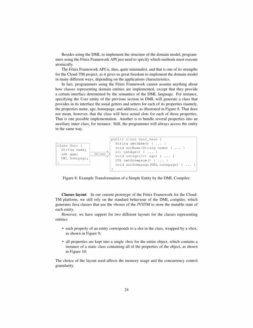
In fact, programmers using the Fénix Framework cannot assume anything abouthow classes representing domain entities are implemented, except that they providea certain interface determined by the semantics of the DML language. For instance,specifying the User entity of the previous section in DML will generate a class thatprovides in its interface the usual getters and setters for each of its properties (namely,the properties name, age, homepage, and address), as illustrated in Figure 8. That doesnot mean, however, that the class will have actual slots for each of those properties.That is one possible implementation. Another is to bundle several properties into anauxiliary inner class, for instance. Still, the programmer will always access the entityin the same way.
Figure 8: Example Transformation of a Simple Entity by the DML Compiler.
Classes layout In our current prototype of the Fénix Framework for the Cloud-TM platform, we still rely on the standard behaviour of the DML compiler, whichgenerates Java classes that use the vboxes of the JVSTM to store the mutable state ofeach entity.
However, we have support for two different layouts for the classes representingentities:
• each property of an entity corresponds to a slot in the class, wrapped by a vbox,as shown in Figure 9;
• all properties are kept into a single vbox for the entire object, which contains ainstance of a static class containing all of the properties of the object, as shownin Figure 10.
The choice of the layout used affects the memory usage and the concurrency controlgranularity.
24

Figure 9: One-to-one mapping between object’s properties and JVSTM’s VBoxes
Figure 10: Mapping the whole state of an entity into a single JVSTM’s VBox
Mapping objects to Infinispan The mapping currently done by the Fénix Frame-work is from vboxes to keys in Infinispan. Each vbox is written to Infinispan into a keythat is composed by the slot name containing the box and the OID of the object towhich the vbox belongs to. So, for example, using the multi-box layout, the name of aUser with OID 1 will be stored under the key "name:1".
As all mutable data is stored within a vbox, including collections representing rela-tionships among objects, the mapping from an object-oriented domain model to Infin-ispan is uniquely determined by how vboxes are used to represent the domain model’sstate. So, when we change the layout of the classes that represent entities, we changealso the mapping done to the underlying Infinispan.
Direct mapping to Infinispan Even though we currently rely on the vboxes tohold the mutable state of each entity, thereby making use of the JVSTM to ensure thetransactional properties of the operations accessing the domain objects, an alternative isto map objects directly into Infinispan. This approach has the advantage of dependingonly on the transactional support provided by Infinispan, accessing the Infinispan cachewhenever an object is accessed within a transaction. We intend to explore this approachas an alternative and compare it to the current approach.
25

3.2.2 Search APIs
A couple of search APIs will compose Cloud-TM. They address different needs andcan be implemented at a different rate in Cloud-TM minimizing the project risks.
The first supported API is support for full-text search queries as provided by Hiber-nate Search. The second API is support for JP-QL (initially a subset and in a secondstep, a more complete subset).
Full-text queries and Hibernate Search
Hibernate Search is an Object/Index Mapper: it binds Apache Lucene full-textindex technology to the Object Oriented world.
Hibernate Search consists of an indexing and an index search component. Both arebacked by Apache Lucene.
Each time an entity is inserted, updated or removed in/from the database, Hiber-nate Search keeps track of this event (through the Hibernate Core event system) andschedules an index update. All index updates are handled without you having to usethe Apache Lucene APIs. This makes the data in the datastore inlined with the indexinformation and thus makes queries accurate.
To interact with Apache Lucene indexes, Hibernate Search has the notion of Di-rectoryProviders. A directory provider will manage a given Lucene Directory type.Traditional directory types are File-System directories and In-memory directories. ForCloud-TM we will make use of an Infinispan directory: the index information will bestored in a distributed fashion in the data grid. The data store will then contain both thedata and the meta-data associated to it. See InfinispanDirectory for more information.
Hibernate Search uses the Lucene index to search an entity and return a list ofmanaged entities saving you the tedious object to Lucene document mapping. Thesame persistence context is shared between Hibernate Core and Hibernate Search. Asa matter of fact, the FullTextEntityManager is built on top of the JPA EntityManager sothat the application code can use the unified javax.persistence.Query API exactly thesame way a JP-QL query would do.
To be more efficient Hibernate Search batches the write interactions with the Luceneindex. There are currently two types of batching. Outside a transaction, the index up-date operation is executed right after the actual database operation. This is really a nobatching setup. In the case of an ongoing transaction, the index update operation isscheduled for the transaction commit phase and discarded in case of transaction roll-back. The batching scope is the transaction. There are two immediate benefits:
• Performance: Lucene indexing works better when operation are executed inbatch.
• ACIDity: The work executed has the same scoping as the one executed by thedatabase transaction and is executed if and only if the transaction is committed.This is not ACID in the strict sense of it, but ACID behaviour is rarely useful forfull text search indexes since they can be rebuilt from the source at any time.
26
You can think of those two batch modes (no scope vs transactional) as the equivalent ofthe (infamous) autocommit vs transactional behaviour in JDBC. From a performanceperspective, the in transaction mode is recommended. The scoping choice is madetransparently. Hibernate Search detects the presence of a transaction and adjust thescoping.
It is recommended - for both your database and Hibernate Search - to execute youroperations in a transaction, be it JDBC or JTA.
Infinispan Lucene Directory
The Directory API in Lucene
The Lucene Directory represents the interface between Lucene’s index writer andit’s search engine to interact with a storage system where the index is kept. In theLucene distributions there are two main implementations: an FSDirectory and a RAMDi-rectory, which store the index elements on the filesystem or in a concurrent hashmap.
An FSDirectory instance is created by invoking a static helper, and in practice adifferent implementation might be created - all options obviously extend FSDirectory -according to the operating system being used: you might get for example a NIOFSDi-rectory or a MMapDirectory, among other implementations. The exact implementationreturned varies among Lucene releases: the factory attempts to provide the optimal im-plementation but might discard some options because of known problems at the timein which the Lucene version was released.
The Directory API is not a complete abstraction of the index structure, only of it’sstorage. So for example it leaks the file concept, file timestamps, directory listing andthe expected contents of these elements are arrays of bytes; IOExceptions are expected,and all of Lucene’s design requires the “filesystem” to implement correctly a “delete onlast close” semantic: Lucene might delete files still being used by some search process,as most filesystem implementations will make sure the file is not actually deleted untilthe last file handle is closed. This guarantee is often not provided by many network-shared filesystems, or poorly implemented / hard to setup properly, and because of thisit’s problematic to share a Lucene index across multiple servers.
A Directory needs to store and load index segments. When an index segmentis completely written and it’s outputstream is closed, then it will never change: in-dex updates including deletions are managed by adding additional information to newsegments, and periodically by configurable optimization strategies old segments aredeleted. A single segment can be written as a single file (compound format), or haveit’s separate logical areas written in separate files; in such a case the filename will rep-resent the segment generation and a three characters file extension will mark the kindof the file. In addition to these segment files which contain the actual index data, twoadditional files contain general meta-data information about the index; these don’t havethe same immutable guarantees as the segment files.
27

Figure 11: Lucene Directory
The directory structure of Lucene assumes that a single IndexWriter instance willapply changes to it at any time; so to protect against multiple writers a locking strat-egy must be selected as well. When using a filesystem based Directory, tipically afilesystem based LockFactory such as NativeFSLockFactory will be used, but in prac-tice any combination of Directory and LockFactory implementations are expected towork together. Such a NativeFSLockFactory would use marker files stored in the indexdirectory, again relying on proper filesystem semantics.
Infinispan Lucene Directory
The Infinispan Directory closely mimicks the filesystem behaviour, extends Lucene’sorg.apache.lucene.store.Directory and implements all methods closely remapping thefile-based API to Infinispan stored objects, it doesn’t change any of the assumptionsLucene has about it’s storage and so the resulting implementation does not preventto use any advanced Lucene feature; also because the Directory API proved histori-cally quite stable the current version 5.0.0.CR2 was tested compatible with all Luceneversions 2.4.x, 2.9.x, 3.0.x, 3.1.x.
Comparing the Infinispan Directory to it’s filesystem based counterpart, there arethree notable differences:
1. Files are split in two main objects:
(a) file contents (a byte[]);
28

Figure 12: Infinispan Lucene Directory
(b) file meta-data (timestamp, length, . . . ).
2. Additional Infinispan specialized Lock Factories are added.
A single file contents might be fragmented in smaller parts
Technically any other LockFactory could be used, as long as it’s able to guaranteethat no two IndexWriters will be opened at the same time.
Performance considerations
Because the file meta-data is read very frequently and because it is significantlysmaller than the file contents, it’s recommended to use a replicated Cache to store thisinformation. For the segments contents instead, a distributed cache is recommended sothat it won’t be required to keep a full copy of the index in the JVM memory of eachnode; still using replication is an option in case of small indexes or plenty of availablememory.
The locks cache uses a third cache, because it’s likely that the first two caches willbe configured to use a CacheLoader, to keep a copy of the index as a backup in some
29

permanent storage, while the locks meta-data is frequently changing information forwhich we don’t need to bother the slower storage engines; especially because if wewhere to shut down all Infinispan nodes, the locking information can be lost, so that inthe remote case of all nodes crashed the service could be restarted without any leftoverlock.
While the locking information and the file meta-data are quite small, the indexsegments might get very big. In Infinispan it’s better to have many smaller values thana couple of very big elements; smaller values are essentially simpler to transfer aroundin the network and make sure that some random JVM won’t have to keep the wholesegment value in memory; so the InfinispanDirectory takes an additional parametercalled chunkSize and it will automatically split values larger than this amount of bytesin several chunks.
Splitting segments in chunks has however two drawbacks:
• Searching will be slower. Lucene is not aware of this buffer split and we mightintroduce some network latency while fetching the next chunk from a remotenode; this doesn’t happen very frequently, and Infinispan can enable a L1 cachetoo, but it’s on a hot path in Lucene’s search process.
• Deleting of a segment is no longer an atomic operation. If the Infinispan Direc-tory detects that a searcher is opening a segment which was split in more than asingle part, it will acquire a cluster-wide “ReadLock”.
Both operations are performed transparently and nor Lucene nor the user has to dealwith it; but it’s worth spending some effort to tune the system in such a way that a goodtradeoff is found between number of values around the cluster and fragmentation.
If Lucene’s IndexWriter was configured to use the LogByteSizeMergePolicy, thiscan be configured to generate segments which don’t exceed a specified size; the strat-egy uses some approximate estimates tough, so it’s still needed to do some experimentsto find a good value; for all segments which where produced of a size below the spec-ified chunksize the readlock won’t be acquired. Also, the MergePolicy only applies tosegments which are merged together; size of newly created segments is affected by theramBufferSizeMB and the maxBufferedDocs parameters of the IndexWriter.
The Infinispan Directory will use the Infinispan based LockFactory by default, butit’s possible to provide a different implementation. Also while it expects three cachesto be used for the above mentioned purposes, when providing a custom LockFactoryonly two caches are needed.
Permanent storage
Infinispan has a notion of CacheLoaders; this is a quite simple interface whichprovides some simple Map operations; in contrary to the name suggestion, it’s notonly able to load information from the implementation but it’s also able to store it.What is of particular interest of the Lucene Directory is that it’s able to use Infinis-pan as a distributed write-behind implementation: the write operations to the cluster
30

can be synchronous, but still have the write operations to the CacheLoader handledasynchronously, and when it will write to the store it will only write the latest currentstate for any key. This means we can “shield” slower storage services from too manychanges, which improves performance and in the case of some cloud services lowersthe IO costs. It’s worth pointing out that while the storage is asynchronous, the infor-mation is safely stored in the grid, so if the writer happens to crash before the valuesare stored, another Infinispan node will still have the data and will be able to load andstore it.
Because some locking meta-data is really not needed to be stored, and because itchanges frequently, it’s adviseable to enable the CacheLoader only on the two maincaches.
Infinispan provides many reference implementations for such a CacheLoader: load-/store to Amazon S3 or any other JClouds supported cloud storage system, to a databaseusing a JDBC datasource, to a filesystem, to Apache Cassandra; of course custom im-plementations can be added to the configuration as well.
Usage
To instantiate a org.infinispan.lucene.InfinispanDirectory the main constructor re-quires the three cache instances. Technically it is possible to pass it a single cache in-stance three times, just you will loose the ability to tune and configure different cacheproperties so this is not advisable unless for unit testing. There are other constructoralternatives to override the default chunkSize and to define a custom LockFactory; inthis case only two caches are needed.
Multiple InfinispanDirectory(s) can use the same caches: to differentiate indexes anindexName parameter is provided, so it’s possible to store multiple indexes in the samecaches as long as they are using different names; this can be considered an analogy ofthe path as used by the filesystem implementation.
When an InfinispanDirectory is created, it extends org.apache.lucene.store.Directoryand all normal Lucene APIs can be used to interact with it.
So several different JVM can share the same in memory Lucene Index and provid-ing very quick replication of index changes to the other nodes.
The limitation in this design is that while it scales pretty well the search aspect, itdoesn’t scale the writer: the IndexWriter will be faster than on disk as it’s writing nowin memory, but you’re still limited to a single IndexWriter at a time; Hibernate Searchdeals with this limitation by providing a queue of changes, a master node is selectedand all changes are sent to this node to be applied on behalf of the other nodes. Otherapplications not using Hibernate Search will have to implement something similar, ordesign the application in such a way that it will always write from a single node.
Support of JP-QL For Hibernate OGM the primary query API is JP-QL. JP-QLsupport will be implemented in two steps:
31

Figure 13: Infinispan Lucene Directory instantiation
• convert JP-QL queries into Lucene queries and execute them via Hibernate Search;
• convert JP-QL queries into Teiid queries where Teiid sources will be the variousLucene indexes exposed via Hibernate Search.
JP-QL to Lucene query
The first step is to write a JP-QL parser that converts JP-QL queries into one ormore Lucene queries (Hibernate Search queries really to benefit from the right level ofabstraction). While this approach is limited in what JP-QL queries are supported, wecan already cover the following functionalities:
• restrictions on the data set ( where user.age > 30, where order.price > 10 anduser.city = ’Paris’ )
• some simple *-to-one joins
The second step is to use Teiid as the query engine.
JP-QL to Teiid query
Teiid is a data virtualization system that allows applications to use data from mul-tiple, heterogeneous data stores.
The heart of Teiid is a high-performance query engine that processes relational,XML, XQuery and procedural queries from federated datasources. Features include
32

Figure 14: Queueing mechanism for changes
33

Figure 15: Architectural Overview of Teiid Query Engine
support for homogeneous schemas, heterogeneous schemas, transactions, and user de-fined functions.
Using Teiid, the query execution would:
• convert the JP-QL query into a Teiid query tree;
• let Teiid convert the query tree into one or more Hibernate Search / Lucenequeries;
• execute Lucene queries on each dedicated index;
• aggregate and or do the cartesian join if necessary;
• return the results to Hibernate OGM.
This second step is a bit further in time but definitely exciting as we would be able todo more complex join operations including for *-to-Many associations.
34

3.2.3 Distributed Execution Framework
The Distributed Execution Framework aims at providing a set of abstractions to sim-plify the development of parallel applications, allowing ordinary programmers to takefull advantage of the processing power available by the set of distributed nodes of theCloud-TM platform without having to deal with low level issues such as load balancing,thread synchronization and scheduling, fault-tolerance, asymmetric processing speedsin different nodes.
The Distributed Execution Framework will consist of two main parts.
1. An extension of the java.util.concurrency framework, designed to transparentlysupport, on top of the in-memory transactional data grid:
• execution of Java’s Callable tasks, which may consume data from the un-derlying data grid;
• synchronization of tasks/threads via, e.g., queues, semaphores, countdownlatches and other classic concurrency tools;
• concurrent, transactional data collections, such as sets, hashmaps, skiplists,arrays;
• processing of data streams, via the definition of pipelines of data streamprocessing tasks.
2. An adapted version of the popular Google’s MapReduce framework. MapRe-duce is a programming model and a framework for processing and generatinglarge data sets. Users specify a map function that processes a key/value pair togenerate a set of intermediate key/value pairs, and a reduce function that mergesall intermediate values associated with the same intermediate k. MapReduceframework enables users to transparently parallelize their tasks and execute themon a large cluster of machines.
The framework is defined as “adapted” because the input data for map reducetasks is taken from the underlying in-memory data grids rather than using inputfiles as it was defined by Google’s original proposal.
Unlike most other distributed frameworks, the Cloud-TM Distributed ExecutionFramework uses data from the transactional data platform’s nodes as input for execu-tion tasks. This provides a number of relevant advantages:
• The availability of the transactional abstraction for the atomic, thread safe ma-nipulation of data allows drastically simplifying the development of higher levelabstractions such as concurrent data collections or synchronization primitives.
• The Distributed Execution Framework capitalizes on the fact that input data inthe transactional data grid is already load balanced (using a Consistent Hashingscheme [5]). Since input data is already balanced execution tasks will be au-tomatically balanced as well; users do not have to explicitly assign work tasksto specific platform’s nodes. However, our framework accommodates users to
35

specify arbitrary subsets of the platform’s data as input for distributed executiontasks.
• The mechanisms used to ensure the fault-tolerance of the data platform, such asredistributing data across the platform’s nodes upon failures/leaves of nodes, canbe exploited to achieve failover of uncompleted tasks. In fact, when a node Ffails, the data platform’s failover mechanism will migrate, along with the datathat used to belong to F, also any task T that was actively executing on F.
Both node failover and task failover policy will be pluggable. An initial imple-mentation will define interfaces to implement various node failover policies butwe will provide only a simple policy that throws an exception if a node fails. Interms of task failure the default initial implementation will simply re-spawn thefailed task until it reaches some failure threshold. Future implementations mightmigrate such a task to another node, etc.
• As the in-memory transactional data grid will provide extensive support for datareplication, more than one node can contain the same entry. Running the sametask on the same node would lead to redundant computations, useful possibly forfault-tolerance reasons, but otherwise superfluous. In order to avoid this prob-lem, it is necessary to schedule the processing of disjoint input data entries innodes, keeping into account the fact that they possibly maintain replicas of thesame data. Thus the input entries for the task have to be split by the frameworkbehind the scene. Once split, approximately the same number of non-overlappedinput entries will be fed to the task on each replica.
Ideally, the split input entries don’t need to be merged or re-split. However, inreality, there are two cases that need to be considered.
The task might run faster on a certain replica while slower on some others even ifthe input entries were split evenly depending on how the task was implementedby user. In such a case, the idle nodes could process the input entries whichwere not processed yet by the busy nodes (i.e. work stealing), only if the cost ofwork-stealing does not cancel the gain.
Also, during the task execution, a replica can go offline for some reason. Insuch a case, other replicas have to take over the input entries that the offlinereplica was assigned to. This is basically implemented in the same way withwork stealing because we can consider the offline node as "the busiest one".
Note that, once the input entries are fed to a node, they can split again to fullyutilize all CPU cores. Proper scheduling needs to be done so that only the samenumber of threads with the number of available cores run at the same time toavoid excessive context switching. Work stealing also needs to be implementedto address the problem mentioned above in a local level.
3.2.3.1 Distributed Execution Model The main interfaces for distributed task ex-ecution are DistributedCallable and DistributedExecutorService. DistributedCallable(see Listing 3) is a subtype of the existing Callable from the java.util.concurrent pack-age. DistributedCallable can be executed in a remote JVM and receive input from
36

the transactional in-memory data grid. The task’s main algorithm could essentiallyremain unchanged, only the input source is changed. Existing Callable implementa-tions will most likely get their input in the form of some Java object/primitive whileDistributedCallable gets its input from the underlying transactional data platform inform of key/value pairs (see Section 3.3). Therefore, programmers who have alreadyimplemented the Callable interface to describe their task units would simply extendtheir implementation to match DistributedCallable and use keys from the data grid asinput for the task. Implementation of DistributedCallable can in fact continue to sup-port implementation of an already existing Callable while simultaneously be ready fordistributed execution by extending DistributedCallable.
Listing 3: DistributedCallable interface
p u b l i c i n t e r f a c e D i s t r i b u t e d C a l l a b l e <K, V, T> ex tends C a l l a b l e <T> {
/ * ** I n v o k e d by e x e c u t i o n e n v i r o n m e n t a f t e r D i s t r i b u t e d C a l l a b l e* has been m i g r a t e d f o r e x e c u t i o n t o a s p e c i f i c Data P l a t f o r m ’ s* node .** @param cache* Data P l a t f o r m ’ s s t o r e whose k e y s are used as i n p u t da ta f o r* t h i s D i s t r i b u t e d C a l l a b l e t a s k* @param i n p u t K e y s* k e y s used as i n p u t f o r t h i s D i s t r i b u t e d C a l l a b l e t a s k* /
p u b l i c vo id s e t E n v i r o n m e n t ( Cache <K, V> cache , Set <K> i n p u t K e y s ) ;
}
DistributedExecutorService is a simple extension of the familiar ExecutorServiceinterface from the java.util.concurrent package. However, advantages of Distribut-edExecutorService are not to be overlooked. Existing Callable tasks, instead of beingexecuted in JDK’s ExecutorService, are also eligible for execution on the distributedCloud-TM data platform. The Distributed Execution Framework would migrate a taskto one or more execution node, run the task and return the result(s) to the calling node.Of course, not all Callable tasks will benefit from parallel distributed execution. Ex-cellent candidates are long running and computationally intensive tasks that can runconcurrently and/or tasks using input data that can be processed concurrently.
The second advantage of the DistributedExecutorService is that it allows a quickand simple implementation of tasks that take input from Infinispan cache nodes, exe-cute certain computation and return results to the caller. Users would specify whichkeys to use as input for specified DistributedCallable and submit that callable forexecution on the Cloud-TM platform. The Distributed Execution Framework’s run-time would locate the appropriate keys, migrate DistributedCallable to target executionnodes and finally return a list of results for each executed Callable. Of course, users canomit specifying input keys in which case Infinispan would execute DistributedCallableon all keys for a specified data store.
37

3.2.3.2 Map Reduce Execution Model The MapReduce model supported by theCloud-TM platform is an adaptation of Google’s original MapReduce. There are fourmain components in each map reduce task: Mapper, Reducer, Collator and MapReduc-eTask.
Each implementation of a Mapper interface (see Listing 4) is a component of aMapReduceTask that is invoked once for each input entry <K,V>, namely a key/valuepair of the underlying in-memory data grid. Given a cache entry <K,V> input pair,every Mapper instance migrated to a node of the data platform, transforms that inputpair into intermediate key/value pair emitted into a provided Collator. Intermediateresults are further reduced using a Reducer.
Listing 4: Mapper interface
p u b l i c i n t e r f a c e Mapper <KIn , VIn , KOut , VOut> ex tends S e r i a l i z a b l e {/ * ** I n v o k e d once f o r each i n p u t cache e n t r y KIn , VOut .* /void map ( KIn key , VIn va lue , C o l l e c t o r <KOut , VOut> c o l l e c t o r ) ;
}
Reducer (see Reducer interface in Listing 5), as its name implies, reduces a list ofintermediate results from map phase of MapReduceTask. The Distributed ExecutionFramework’s environment creates one instance of Reducer per execution node.
Listing 5: Reducer interface
p u b l i c i n t e r f a c e Reducer <KOut , VOut> ex tends S e r i a l i z a b l e {
/ * ** Combines / r e d u c e s a l l i n t e r m e d i a t e v a l u e s f o r a p a r t i c u l a r* i n t e r m e d i a t e key t o a s i n g l e v a l u e .** /VOut r e d u c e ( KOut reducedKey , I t e r a t o r <VOut> i t e r ) ;
}
Collator (see Collator interface in Listing 6) aggregates results from Reducers exe-cuted on the Cloud-TM platform and assembles a final result to return to an invoker ofMapReduceTask. Collator is applied to the final Map<KOut,VOut> result of MapRe-duceTask.
Listing 6: Collator interface
p u b l i c i n t e r f a c e C o l l a t o r <KOut , VOut , R> {/ * ** C o l l a t e s a l l r educed r e s u l t s and r e t u r n s R t o i n v o k e r* o f d i s t r i b u t e d t a s k .** @return f i n a l r e s u l t o f d i s t r i b u t e d t a s k c o m p u t a t i o n* /R c o l l a t e ( Map<KOut , VOut> r e d u c e d R e s u l t s ) ;
}
38

Finally, MapReduceTask is a distributed task uniting Mapper, Reducer and Colla-tor into a cohesive large scale computation to be transparently parallelized across theCloud-TM Data Platform nodes. Users of MapReduceTask need to provide a cachewhose data is used as input for this task. The Distributed Execution Framework’s ex-ecution environment will instantiate and migrate instances of provided mappers andreducers seamlessly across Infinispan nodes.
39

3.3 Reconfigurable Software Transactional MemoryAt the light of the evaluation of the project’s enabling technologies reported in deliv-erable D1.1, the Consortium has reached the agreement on basing the implementationof the in-memory transactional data grid on Infinispan [6], a recent open source projectled by JBoss/Red Hat.
The choice has been motivated by the following key considerations.
1. Despite being a quite recent project, Infinispan could benefit from the contribu-tions from a wide and active community which enriched with a wide range ofappealing features that would have to be implemented anyway if we opted todevelop from scratch this essential component of the Cloud-TM platform. Fur-ther, representing the reference clustering solution for JBoss Application Server,which is probably the most popular open-source J2EE AS at current date, Infin-ispan is widely known in the middleware software industry. These features bringtwo main advantages: on one side, the Cloud-TM project will be able to relyon a robust and well documented piece of software, which will be enriched tomeet the requirements of the Cloud-TM project allowing the partners to focus onintegrating innovative research results (such as new replication/distribution algo-rithms, or self-tuning mechanisms); on the other it will ensure the high visibilityof the project itself in the industrial arena, maximizing the chances of successfulexploitation of the project’s research results.
2. Infinispan exposes a JSR-107 (JCACHE) compatible Cache interface [7] andprovides JTA compatibility [8], thus leading to an easy integration in most ofthe existing architectures in the industry world, which is expected to ultimatefacilitate the adoption of the Cloud-TM platform as well.
3. Infinispan is based on a modular and scalable, object-oriented architecture, whichentails the possibility to extend the existing modules with minimum intrusive-ness. This allows members of the Consortium to focus much more on challeng-ing research problems (such as self-tuning and design of new replica/distributionalgorithms) than pure software engineering issues.
In the remainder of this section we will first provide an high level overview of the cur-rent architecture of Infinispan (v 5.0.0 CR2), and then focus on the plans concerninghow it will be enriched to meet the Cloud-TM’s requirements of dynamic reconfigura-tion.
3.3.1 Infinispan’s main operational modes
Infinispan architecture is extremely flexible and supports a range of operational modes.Standalone (non-clustered) mode: in this mode, Infinispan acts as a Software
Transactional Memory. Unlike classical STMs, however, Infinispan does not ensureserializability (or opacity) [9], but, in order to maximize performance, it guaranteesmore relaxed consistency models. Specifically, it ensures the ISO/ANSI SQL isolationlevels Read-committed and Repeatable-read isolation levels [9], in addition to what
40

is called Write skew anomaly avoidance. In the following, we briefly overview theseisolation criteria, and how they are ensured.
• In the read committed isolation level, whenever the application wants to read anentry from Infinispan for the first time, the application is provided directly withthe current value in the underlying data container that only contains committedvalues. When and if the application writes an entry, the modifications are notimmediately applied; conversely, the updated data value is stored in a privatetransaction’s workspace. Any later read by the same transaction returns the valuethat had previously written.
• In the repeatable read isolation level when the application issues for the firsttime a read request for an entry, it is provided with the value from the committedvalues container; this value is stored in a private transaction’s workspace, and isreturned whenever a new read operation is issued on that same data item.
• If the write-skew check is enabled, Infinispan checks if, between a read and awrite operation on a data item X issued from a transaction A, there has been sometransaction B that has updated (and committed) X. In this case the transaction Ais aborted.
Independently from the isolation level, read operations are always lock-free; on theother side, every write operation requires the acquisition of a lock in order to avoid con-current modifications on the same entry. Infinispan provides the per-entry lock mode,meaning that each <key,value> pair is protected by its own lock, and the striped lockmode, meaning that each lock is shared by a set of <key,value> pairs. This secondoption reduces memory consumption for lock management, but has the drawback ofincurring in false lock contentions. Lock contention is solved through a simple andconfigurable timeout scheme; further, Infinispan provides a simple and lightweightdeadlock detection mechanism to detect cyclic dependencies between pairs of transac-tions.
Full replication mode: in this mode, Infinispan is deployed over a set of intercon-nected nodes, each one holding a replica of the same key set. This mode is mainlyintended for small scale deployments, given that the need to propagate updates to allthe nodes in the system hampers the global scalability of this operational mode. Thereplication mechanism employed by Infinispan is based on the usage of the classicaltwo phase commit protocol, which ensures that, in order for a transaction to be com-mitted, it must acquire locks successfully across all the nodes in the platform (and thusensuring replica-wide agreement on the transaction serialization order).
More in detail, upon the issuing of a commit request from a transaction, the preparephase is initiated: the set of the keys updated by the transaction together with therelevant modification that it wants to perform is broadcast to all nodes. The transactionis then re-run remotely on every node following the aforementioned locking scheme; ifa node can successfully acquire all the locks needed, it sends an acknowledgement tothe issuer of the prepare phase, otherwise it communicates its impossibility to proceed.If all nodes send a positive reply, then the node of the original transaction sends a final
41

commit message and all nodes can safely propagate the modifications on the affectedkeys.
Partial replication mode: in this mode every Infinispan replica stores a subset ofthe data globally managed by the system; every <key, value> pair is replicated (us-ing a Consistent Hashing scheme [5] to distribute keys among nodes, described in thefollowing) over a subset of the total nodes, thus leading to the possibility to meet avail-ability and fault tolerance requirements without the drawbacks that are endemic to thefull replicated mode. Upon the commit of a transaction, only the nodes which storekeys affected by it are involved in the two-phase commit.
3.3.2 High level architecture
In this section we will provide some details about the inner structure of Infinispan,describing the main building blocks that are at its core.
At the highest level of abstraction, the main components are the following: theCommands, which are objects that encapsulate the logic of the methods invoked bythe user on the Cache; the Visitors, which are intended to “visit” the commands inorder to execute them; special Visitors are the Interceptors, which act as a chain andinteract with the subsystems which are affected by a command; the Managers, that areresponsible for managing the subsystems.
The main building blocks of the Infinispan architecture are shown in Figure 16,and a brief description for each of them is provided in the following. We start bydescribing the modules that are common to any operational mode of Infinispan (whichwe call Core modules). Next we describe, in an incremental fashion, the additionalmodules that come into play in the full and partial replication modes.
Core Modules
1. DataContainer: it embeds a ConcurrentHashMap which ultimately stores the<key,value> pairs handled by users. Infinispan gives to the user the possibility todefine a lifespan for the entries, after which they are removed from the data con-tainer. Moreover it supports several eviction algorithms (FIFO, LRU, LIRS [10])in order to avoid extreme usage of the memory heap. Evicted entries are com-pletely removed, coherently with their lifespan, or stored through the registeredCacheLoader, if any. Passivation of entries is also supported.
2. CommandFactory: it is responsible for mapping methods invoked by the appli-cation into commands which are visited by the Interceptors.
3. EntryFactory: it is responsible for wrapping DataContainer’s entries when ac-cessed. This component interacts with TxInterceptor, which is responsible forimplementing the concurrency control algorithms that enforce the isolation levelspecified by the user.
42

Figure 16: Architectural Overview of Infinispan.
4. LockManager: it deals with all aspects of acquiring and releasing locks for cacheentries. It can support both lazy locking mode, meaning that upon a write thelock is taken only locally, postponing the system-wide lock acquisition until theprepare phase, and eager locking, in which a lock is taken immediately on allInfinispan’s replica when a request is issued. As already mentioned, lock con-tentions are solved through timeout and in the case of multiple transactions wait-ing for the same lock fairness is not guaranteed. The Interceptor responsible forinteracting with this component is the LockingInterceptor.
5. Transaction Manager: it allows to define transactions’ boundaries. Infinispanis shipped with a simple DummyTransactionManager, but any JTA complianttransaction manager can be used. Infinispan provides also a XAAdapter classwhich implements the XAResource interface in order to support distributed trans-actions among heterogeneous resources.
6. InterceptorChain: it is the entry point for any command to be performed. Ittriggers the visit of the command from all the registered interceptors.
7. ComponentRegistry: it acts as a lean dependency injection framework, allowingcomponents and managers to reference and initialize one another.
43

Additional modules involved in full replication mode
1. Transport: it provides a communication link with remote caches and allows re-mote caches to invoke commands on a local cache instance. This layer ultimatelyrelies on JGroups, to implement lower level’s Group Communication Service’sabstractions (such as view synchrony [11], failure detection, reliable broadcast,etc).
2. CommandAwareDispatcher: it’s a JGroups RPC dispatcher which knows how todeal with replicated commands.
3. InboundInvocationManager: it is a globally-scoped component which is able toreach named caches and trigger the execution of commands from remote onesby setting up the interceptor chain for them.
4. RpcManager: provides a mechanism for communicating with other caches inthe cluster, by formatting and passing requests down to the registered Transport.This component dialogues directly with the ReplicationInterceptor, which trig-gers the re-execution of transactions via remote procedures calls.
5. StateTransferManager: it handles generation and application of state on the cache.
Additional modules involved in partial replication mode
1. DistributionManager: it is responsible both for handling the correspondence be-tween any data entry and its owner Infinispan node and the caching policy ofentries which are retrieved from remote instances when locally accessed. Itcommunicates with the DistributionInterceptor which is mutually exclusive withrespect to the Replication one.
To determine which instances store which entries, the DistributionManager ex-ploits a Consistent Hashing algorithm [5]: both keys and caches are hashed ontoa logical circle and each cache contains all keys between itself and the next clock-wise one on the circle. This mechanism allows to detect the owner of an entrywithout additional communication steps and is extremely efficient since upon theleave/join of a node, only a reduced set of entries has to be redistributed, involv-ing in this operation only the nodes which are logically adjacent to the one thathas just left/joined the system.
This component is also responsible for managing a level one cache aimed attemporary storing entries which are not a burden, coherently with the consistenthashing, of a specific instance. If a transaction requests an entry that is not localto the node, a remote procedure call is issued aimed at retrieving and storing itin the level one cache. DistributionManager is responsible for defining evictionpolicies for those entries.
Moreover, the DistributionManager module is in charge of removing from theDataContainer entries which a node is no longer responsible for (e.g. upon thejoin of a new instance) or of moving them to the level one cache.
44

3.3.3 Extensions to support complex dynamic reconfigurations
In order to deal with runtime reconfigurations, Cloud-TM enriches Infinispan’s ar-chitecture with a Reconfiguration Manager: it is designed to communicate with theAutonomic Manager via JMX and, when a reconfiguration request is triggered, it or-chestrates the switch operations of the various components via the native Infinispan’svisiting mechanism. In particular, a ReconfigurationCommand is defined, which con-tains a set of ConfigInfo objects, one per component, that contain information aboutthe operations to be performed on every subsystem.
45

Figure 17: Infinispan’s Expanded Command Hierarchy.
46
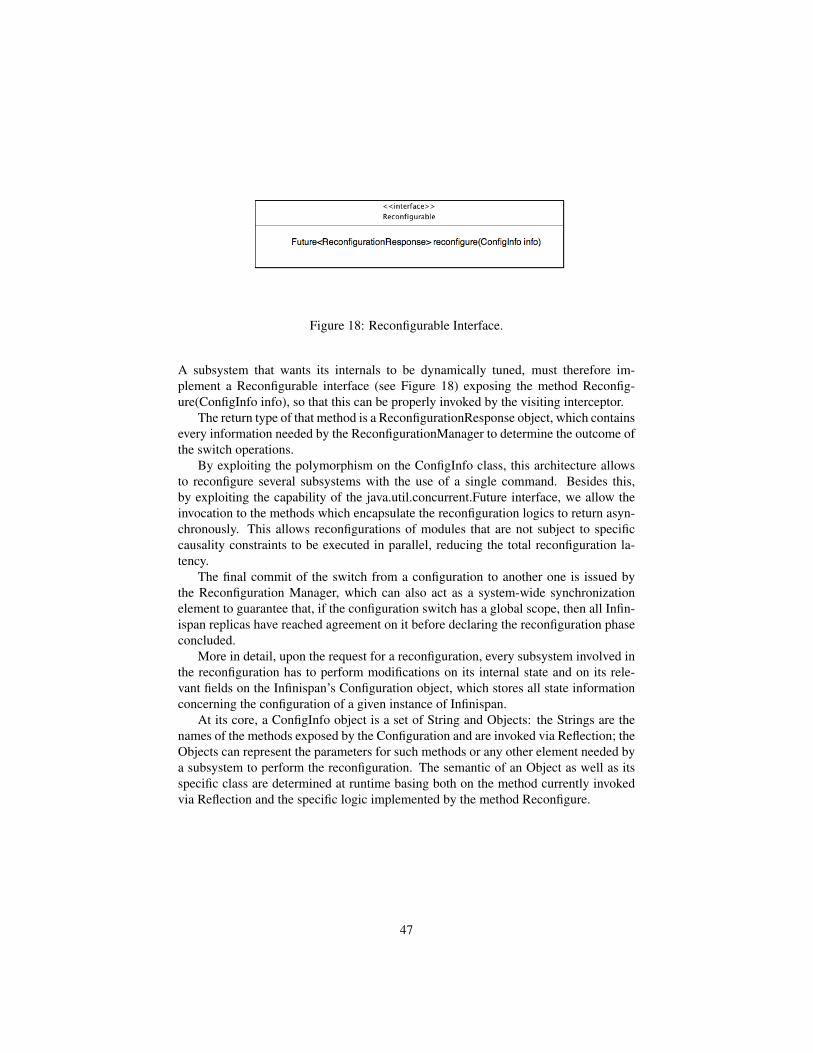
Figure 18: Reconfigurable Interface.
A subsystem that wants its internals to be dynamically tuned, must therefore im-plement a Reconfigurable interface (see Figure 18) exposing the method Reconfig-ure(ConfigInfo info), so that this can be properly invoked by the visiting interceptor.
The return type of that method is a ReconfigurationResponse object, which containsevery information needed by the ReconfigurationManager to determine the outcome ofthe switch operations.
By exploiting the polymorphism on the ConfigInfo class, this architecture allowsto reconfigure several subsystems with the use of a single command. Besides this,by exploiting the capability of the java.util.concurrent.Future interface, we allow theinvocation to the methods which encapsulate the reconfiguration logics to return asyn-chronously. This allows reconfigurations of modules that are not subject to specificcausality constraints to be executed in parallel, reducing the total reconfiguration la-tency.
The final commit of the switch from a configuration to another one is issued bythe Reconfiguration Manager, which can also act as a system-wide synchronizationelement to guarantee that, if the configuration switch has a global scope, then all Infin-ispan replicas have reached agreement on it before declaring the reconfiguration phaseconcluded.
More in detail, upon the request for a reconfiguration, every subsystem involved inthe reconfiguration has to perform modifications on its internal state and on its rele-vant fields on the Infinispan’s Configuration object, which stores all state informationconcerning the configuration of a given instance of Infinispan.
At its core, a ConfigInfo object is a set of String and Objects: the Strings are thenames of the methods exposed by the Configuration and are invoked via Reflection; theObjects can represent the parameters for such methods or any other element needed bya subsystem to perform the reconfiguration. The semantic of an Object as well as itsspecific class are determined at runtime basing both on the method currently invokedvia Reflection and the specific logic implemented by the method Reconfigure.
47

Figure 19: Extended Visitor Interface.
The above described architecture, thanks to the Reconfiguration Manager, encom-passes also the possibility to orchestrate complex reconfiguration operations whichwould be difficult to split into several, component-specific minor reconfigurations. Forinstance, this design pattern allows to modify at runtime the interceptor chain. The lat-ter can therefore be seen as both the means through which ReconfigurationCommandare spread in the system, and as a reconfigurable object itself. A practical examplefor this scenario is the switch from Replicated to Distributed mode, which entails thesubstitution of the ReplicationInterceptor with the DistributionInterceptor.
48

3.4 Reconfigurable storage systemWithin the Cloud-TM platform, in-memory data replication represents the referencemechanism to ensure fault-tolerance and data reliability without incurring in the over-heads of synchronous logging to persistent storages.
Nevertheless, data persistence (in particular asynchronous disk logging) may stillrepresent an indispensable requirement for a large class of Cloud applications, in par-ticular as a means to ensure disaster recovery capabilities.
As mentioned while illustrating the high level architecture of the Cloud-TM plat-form in Section 2, the component in charge of ensuring data durability is the “Recon-figurable Storage System” layer. The key requirements identified for this component(R20-R22 of the deliverable D1.1 “User Requirements Report”) consisted in achievingmaximal portability towards storage systems of different nature, ranging from local/dis-tributed file systems to Cloud-oriented storage services (e.g. Amazon’s S3, Google’sBig Table, Hadoop’s Hbase, Cassandra).
This requirement is perfectly met by the software architecture currently employedby Infinispan’s, so called, CacheLoader/CacheStore modules. Infinispan’s approachto dealing with external persistent storages, in fact, is based on a modular, plug-inbased, architecture that allows to neatly encapsulate the inherent peculiarities underly-ing the interactions with heterogeneous persistent storages via a homogeneous abstrac-tion layer. Indeed, the high flexibility of Infinispan’s architecture for interfacing withpersistent storage, as well as the availability of plug-ins for a plethora of alternativepersistent storage technologies, have been some of the main reasons that have led tochoose Infinispan as the backbone of the infrastructure of Cloud-TM.
In fact, this choice will allow the consortium to exploit the existing Infinispan’scodebase and focus on the research issues associated with the dynamic reconfigurationand self-tuning of the persistent storage layers. These will include the design of auto-nomic mechanisms aimed both at tuning the individual parameters of connected datastores, as well as the run-time switch/add/remove of persistent storages on the basis ofthe current workload and of QoS/cost constraints.
The architecture of the Reconfigurable Storage System is illustrated by the diagramin Figure 20. It will consist of two main logical blocks: a set of plugins allowinginterfacing Infinispan with heterogeneous data stores, and a Persistent Store Manager,which will expose a Generic Reconfigurable Component Interface (see Section 3.3) toallow monitoring and tuning by the Autonomic Manager.
These two modules are described in the following.
3.4.1 Interfaces towards Persistent Storages
As already discussed, in order to achieve interoperability with heterogeneous persis-tent stores, the Cloud-TM platform will exploit the modular plug-in based adopted byInfinispan.
The key abstraction used in Infinispan to support interactions with external datastores are the CacheLoader and CacheStore interfaces, which expose, respectively, aset of methods aimed at retrieving and storing data from the persistent store, both intransactional and non transactional context. As shown in the class diagram in Figure
49
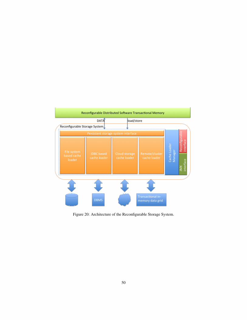
Reconfigurable Distributed So4ware Transac7onal Memory
Persistent storage system interface
Remote/cluster cache loader
Cloud storage cache loader
JDBC based cache loader
File system based cache
loader
Transac7onal in‐memory data grid DBMS
Reconfigurable Storage System
load/store DATA
Cache Loader
Manager
Reconfi
gurable
interface
JMX
interface
Figure 20: Architecture of the Reconfigurable Storage System.
50

21 (which is using UML notation), these interfaces are sufficiently generic to allowencapsulating the specific implementation details associated with external data storesof different nature, including (local/distributed) file-systems, relational DBMSs andCloud-based storage systems.
Referring to Figure 20, the Persistent Store Manager is responsible for handlingthe relations between a specific Infinispan’s instance and the underlying CacheLoad-ers/CacheStores, supporting, whether needed, the simultaneous interfacing towardsmultiple data stores. The interaction between these modules and Infinispan’s core isachieved via the following interceptors, which are injected in the interceptors chain atthe start-up or during the reconfiguration phase (see Section 3.3.3):
1. CacheLoaderInterceptor: this interceptor is responsible for fetching data fromthe connected data stores. Whenever a read/update operation is performed onthe data grid and the requested entries are not found in cache, every active cacheloader configured for that cache tries to fetch data from the corresponding con-nected storage until a valid not-null element of data is found.
2. CacheStoreInterceptor: this interceptor is responsible for writing modificationsback to the store; they are stored back through the CacheStore, either after eachoperation call, if it is not performed in transactional context, or upon the commitof the relevant transaction.
Cache loaders can be grouped in four distinct categories, depending on the store typethey handle.
1. File system based cache loaders: they are aimed at providing an abstraction layerto connect to regular local or distributed filesystems (e.g. Cassandra).
2. JDBC based cache loaders: their purpose is to provide connectivity towardsJDBC-accessible databases.
3. Cloud storage cache loaders: they are intended to allow the exploitation of datastorage facilities over the cloud (e.g. Amazon’s S3).
4. Remote cache loaders: they provide the possibility to exploit another cache as alower layer used to load data.
Eviction and passivation
When configured to interact with an external persistent data store, the Reconfig-urable Distributed Software Transactional Memory can be seen as a volatile cache hav-ing a smaller capacity with respect to the persistent storage. In this case the issue ofwhich entries should be kept in memory, and which stored on the persistent data store,naturally arises.
51

Figure 21: Key Interfaces Used to Achieve Interoperability between a Number of Het-erogeneous Persistent Data Stores.
52
Infinispan already provides advanced supports for this kind of use cases, imple-menting a set of alternative policies for what concerns cache eviction, write-back/write-through, synchronous/ asynchronous propagation of updates.
Cache loaders/stores can also be used to enforce entry passivation and activation.Cache passivation is the process of removing an object from in-memory cache andwriting it to a secondary data store on eviction; cache activation is the dual process.
Even though there is no direct relationship between eviction and cache loading,when passivation is enabled, such a relationship arises: writes to the persistent storevia the cache loader only occur as a part of the eviction process. Data is deleted fromthe persistent store when the application reads it back into memory: in this case, what’sin memory and what’s in the persistent store are two subsets of the total informationset, with no intersection between the subsets.
3.4.2 Run-time reconfiguration support
In order to meet Cloud-TM reconfiguration requirements, some of the described com-ponents are enhanced in such a way to maintain compatibility with the described archi-tecture while exposing new methods in order to be reconfigurable in compliance withthe visiting mechanism on the ReconfigurationCommand triggered by the Reconfigu-ration Manager that will be integrated into Infinispan (see Section 3.3.3).
In particular the Persistent Store Manager will be requested to implement the Re-configurable interface, and the CacheLoaderInterceptor and CacheStoreInterceptorswill be extended to implement the Extended Visitor Interface, both defined in Sec-tion 3.3.3.
The latter will allow Infinispan’s Reconfiguration Manager to coordinate the dy-namic reconfiguration of the mechanisms employed to interact with external data storesusing the same, general approach described in Section 3.3.3 to deal with reconfigu-rations of its other internal components. Specifically, the Reconfiguration Managerwill be able to provide reconfiguration instructions, encoded as a ConfigInfo objectwithin the Reconfiguration Command, to the CacheLoader and CacheStore intercep-tors. These, in their turn, will trigger reconfigurations of the persistent storage policiesby invoking the reconfigure() method exposed by the Persistent Storage Manager viaits Reconfigurable interface.
For what concerns the monitoring and tuning of this layer by the Autonomic Man-ager, given that the Persistent Storage Manager is implemented in Java, it will exposestandard JMX interfaces, and rely on the XML-based advertisement mechanism de-scribed in Section 3.1 in order to expose meta-data concerning which of its parametersshould be monitored/tuned and on the basis of what utility functions.
53

4 Autonomic ManagerIn this Section we discuss architectural aspects concerning the design of the AutonomicManager, namely the component in charge of monitoring and piloting the automatictuning and scaling of the Data Platform of Cloud-TM.
We start by describing, in Section 4.1, the mechanisms that will be employed toallow applications to express their QoS/cost constrains to the Cloud-TM platform.
In Section 4.2, we discuss the architectural choices underlying the developmentof the Workload and Performance Monitor. Note that this module has been alreadydeveloped, and the corresponding prototype has been made publicly available as thedeliverable D3.1.
Section 4.3 describes the architecture that has been planned for the Workload Ana-lyzer. This component is in charge of processing the raw data streams generated by theWorkload and Performance Monitor, providing differentiated views based on differen-tiated aggregation rules in order to generate workload characterizations (and forecasts)for individual platform components/layers, as well as to generate alert signals in caseof violations of the specified QoS/cost constraints.
Finally, in Section 4.4, we present the envisioned architecture of the AdaptationManager, namely the component that will host the optimization logic employed toguide the self-tuning of the various components of the Data Platform, as well the auto-matic provisioning of resources from the IaaS provider(s).
54

4.1 QoS APIThe QoS API will provide a means for supporting a structured interaction between theAutonomic Manager and customer applications. The objective of the interaction is thespecification of a agreement expressed in terms of:
• a set of parameters, and the associated values, globally defining the customerexpectation, in terms of QoS to be matched by the Cloud-TM platform at run-time, and
• the customer agreed upon obligations/costs for obtaining the level of service asspecified via the QoS selected parameters/values.
Clearly, such an API must be flexible, in order to support interactions aimed at definingdifferentiated QoS/cost bindings. Anyway, constraints must be considered in order toprevent scenarios where meaningless agreements could not eventually be committedby the involved parties. In our architectural approach, we intend to define the QoS APIas a parametrizable XML-based template, whose structure will define a meta-modelaccording to which any meaningful agreement can be actually instantiated.
We recall that one of the main objectives of Cloud-TM is the exemplification ofthe applications’ development process, which must be also reflected in a simplifiednegotiation supported via the selected QoS API. This should be reflected in that thetemplate should be able to express the obligations of the customer (hence requirementsto be matched by customer applications) in a very synthetic and simplified manner. Oneimmediate advantage would be in avoiding the need for application developers to carryout very extensive and complex profiling activities in order to be able to determinewhether those obligations can be actually met when running on top of the Cloud-TMplatform.
On the basis of the above reasoning, we can roughly identify the below listed threedifferentiated operating modes characterizing any application potentially running ontop of the Cloud-TM platform:
1. the application does not currently accesses the data layer;
2. the application is currently accessing the data layer via an individual data accessoperation (either read or write);
3. the application is currently accessing the data layer within a transactional contextpossibly entailing multiple data access operation (either read or write).
Any KPI related to point 1 is independent of the data layer performance. Instead itwould essentially express performance aspects in relation to the computational powerand/or the deploy characterizing the infrastructure hosting the application. On the otherhand, KPIs associated with the operating modes 2 and 3 would express performancedependencies on the data layer behaviour.
Performance guarantees when running in mode 1 would therefore be essentiallyrelated to the scale up/down of the computational power associated with the underlyinginfrastructure. On the other hand, performance guarantees when running in modes 2
55

and 3 would require providing statistical bounds on the timing of operations at the levelof the data layer. Point 1) will be reflected in our template by expressing guarantees onper-thread computational power and bandwidth, once fixed the maximum number ofconcurrent threads. On the other hand, for modes in points 2 and 3, the template wouldexpress guarantees on:
• the average latency for the access in read or write mode to a single object hostedby the data-platform (i.e. out of a transaction);
• the x percentile of the response time for the access in read or write mode to aobject hosted by the data-platform (i.e. out of a transaction);
• the average latency for the execution of a transaction;
• the x percentile of the response time for the execution of a transaction.
The above guarantees should be coupled with obligations to be respected by the appli-cation code expressed in terms of (A) the maximum CPU time requested while runningwithin a transactional context (this is needed for point 3), and (B) the maximum levelof conflict exhibited by the application, that we easily express via our template as thelikelihood that the read/write sets associated with two concurrent transactions (or trans-actional accesses to single data) have null intersection.
We note that, compared to classical scenarios where QoS parameters are expressedby essentially relying on the volume of requests by the customer, here we have intro-duced a bit of additional information, related to the customer application profile. Thisis related to that the Cloud-TM platform does not offer and end-delivered service, buta data access “middleware service” on top of which the customer application runs.Hence, violations of the performance guarantees can be caused by factors that are outof the control of the Cloud-TM Autonomic Manager, such as application run-time thatdoes not conform with an expected profile, which may have strong negative effectsjust due to the particular, transactional nature of the services offered by the Cloud-TMmiddleware.
As for the technological support to the template definition, and so to the instanti-ation of the QoS API, our choice to rely on XML is motivated by the fact that it hasbeen extensively adopted in the context of Web Service Agreement Specification [12].
56

4.2 Workload and Performance MonitorThe Workload and Performance Monitor (WPM) is a building-block component of theAutonomic Manager of the Cloud-TM platform. WPM must implement monitoringfunctionalities and mechanisms aimed at gathering statistics related to differentiatedlayers belonging to the Cloud-TM platform. As stated in the deliverable D1.1 “UserRequirement Report”, these layers entail the hardware level (i.e. physical or virtualizedhardware resources) as well as logical resources, such as data maintained by the DataPlatform. The set of User Requirements directly impacting the structure of WPM arethose in the interval R.38-R.43 and R.45. Generally speaking, these requirements entailindications on:
• the type of resources whose usage must be profiled/monitored;
• the nature (e.g. in terms of standardization or de-facto reference) of the API/ap-plications on top of which monitoring operations must be built;
• the on-line/real-time operative mode of the monitoring system.
Anyway, WPM is also in charge of monitoring the performance parameters which willbe selected as representative for the negotiated QoS guarantee.
As pointed out within the deliverable D1.2 “Enabling Technologies Report”, onereference framework for the building of monitoring systems in the context of Cloudbased platforms is Lattice [2], which has also been used as an architectural building-block within the RESERVOIR project [13]. At a certain level of abstraction, Lattice canbe seen as a technology providing the skeleton of a distributed, scalable data-gatheringsystem, hence being suited for instantiating a distributed, scalable monitoring platform.
The skeleton provided by Lattice is conceptually very simple, and is based on areduced number of interacting components, each one devoted (and encapsulating) aspecific task belonging to distributed data-gathering activities. In terms of interac-tion abstraction, the Lattice framework is based on the producer-consumer scheme,where both the producer and consumer components are, in their turn, formed by sub-components, whose instantiation ultimately determines the functionalities of the imple-mented monitoring system. A producer contains data sources which, in turn, containone or more probes. Probes read data values to be monitored, encapsulate measureswithin measurement messages and put them into message queues. Data values can beread by probes periodically, or as a consequence of some event. A message queue isshared by the data source and the contained probes. When a measurement message isavailable within some queue, the data source sends it to the consumer, which makes itavailable to reporter components. Overall, the producer component injects data that aredelivered to the consumer. Also, producer and consumer have the capability to interactin order to internally (re)configure their operating mode. Three logical channels aredefined for the interaction between the two components, named:
• data plane;
• info plane;
• control plane.
57

The data plane is used to transfer data-messages, whose payload is a set of measures,each kept within a proper message-field. The structure of the message (in terms ofamount of fields, and meaning of each filed) is predetermined. Hence fields do notneed to be explicitly tagged so that only data-values are really transmitted, togetherwith a concise header tagging the message with very basic information, mostly relatedto source identification and its timestamp. Such a structure can be anyway dynamicallyreconfigured via interactions supported by the info plane.
This is a very relevant feature of Lattice since it allows minimal message footprintfor (frequently) exchanged data-messages, while still enabling maximal flexibility, interms of on-the-fly (infrequent) reconfiguration of the monitoring-information structureexchanged across the distributed components within the monitoring architecture.
Finally, the control plane can be used for triggering reconfiguration of the producercomponent, e.g., by inducing a change of the rate at which measurements need to betaken.
Notably, the actual transport mechanism supporting the planes is decoupled fromthe internal architecture of producer/consumer components. Specifically, data aredisseminated across these components through configurable distribution mechanismsranging from IP multicast, to publish/subscribe systems, which can be selected on thebasis of the actual deploy and which can even be changed over time without affectingother components, in term of their internal configuration. The framework is designedto support multiple producers and multiple consumers, providing the chance to dy-namically manage data source configuration, probes activation and deactivation, datasending rate, redundancy and so on. Overall, such a model well fits highly dynamicdistributed environments.
The Lattice framework is based on Java technology, so that producer/consumercomponents encapsulate sub-components that are mapped onto a set of Java threads,each one taking care of specific activities. Some of these threads, such as the data-source or the data-consumer constitute the general purpose backbone of the skeletonprovided by Lattice. Other threads, most notably the probe-thread and the reporter-thread, implement the actual logic for taking/reporting measurement samples. Theimplementation of these threads can be seen as the ad-hoc portion of the whole moni-toring infrastructure, which performs activities tailored to specific measurements to betaken, in relation to the context where the monitoring system operates.
By relying on Java, portability issues are mostly limited to the implementationof the ad-hoc components. As an example, a probe-thread based on direct accessto the “proc” file system for gathering CPU/memory usage information is portableonly across (virtualized) operating systems supporting that type of file system (e.g.LINUX). However, widening portability across general platforms would only entail re-programming the internal logic of this probe, which in some cases can even be doneby exploiting, e.g., pre-existing Java packages providing platform-transparent accessto physical resource usage. As for this aspect, we plan to incorporate within the WPMarchitecture cross-platform libraries such as SIGAR, JConsole, JnetPCap, and JPcap,which offer methods to extract relevant data from the devices of interest, across dif-ferent operating systems and architectures. Among these four libraries, the most com-plete is surely SIGAR which has the capability to access information exposed by theoperating system (e.g. CPU utilization, memory consumption, network activities) in-
58

Figure 22: Architectural Scheme for the Workload and Performance Monitor.
dependently of the underlying actual platform. In our architectural plan, it will betherefore used for instantiating wrappers fitting with differentiated platforms, such asLinux, Windows and Mac OS X.
The aforementioned portability considerations also apply to reporter-threads, whichcan implement differentiated, portable logics for exposing data to back-end applica-tions (e.g. by storing the data within a conventional database).
Another relevant aspect for Lattice is that the above mentioned activities (i.e. threads)can be run within dedicated demon processes, or within proper processes acting inside(i.e. as a part of) the monitored platform. In the latter case, the probes even have accessto the state of the objects belonging to the monitored process, either via informationshared across threads, or by exploiting internal audit-API provided by the running soft-ware. This facilitates the integration of the monitoring system in cases where the objectactivities are of interest to the monitoring process, which we expect to be the case forthe Cloud-TM platform. As for the latter aspect, User Requirements in the range R.41-R.43 just deal with collection of statistics related to the data-layer (including innerdistribution/replication protocols). For Java based components, Lattice probes can berun as demons interacting with the components’ native audit system (or extensions ofthis system tailored to Cloud-TM), via the JMX framework, which will result in a quitenatural integration process.
Figure 22 shows the general architecture of the WPM belonging to Cloud-TM. Ithas been defined according to the need for supporting the following two main function-
59

alities:
• statistical data gathering (SDG);
• statistical data logging (SDL).
The SDG functionality architecturally maps onto an instantiation of the Lattice frame-work, with Cloud-TM specific probes and collectors.
The computational nodes of the network (e.g. Virtual Machine(VM)s) could belogically grouped. Each group will entail per-machine probes targeting two types ofresources: hardware/virtualized and logical. Statistics for the first kind of resources aredirectly collected over the Operating System (or by standard OS decoupled libraries)as hinted before, while statistics related to logical resources (e.g. data-platform) arecollected directly at application level, e.g. by using the JMX Framework for Java com-ponents. The data collected by the probes are sent to the Lattice Producer componentvia facilities directly offered by the framework. Each Producer is coupled with one ormany probes and it is responsible of managing them.
The Consumer is the Lattice component that receives the data from the Producers,via differentiated messaging implementations, which could be selected on the basis ofthe specific system deploy. We envisage a LAN based clustering scheme such that theConsumer is in charge of handling one or multiple groups of machines belonging to thesame LAN. Anyway, the number of Consumers in not meant to be fixed, instead it canbe scaled up/down depending on the amount of instantiated probes/Producers. Overall,the Consumer could be a centralized or a distributed process, thus supporting specificscalability/availability levels.
Beyond collecting data from the Producers, the Consumer is also in charge of per-forming a local elaboration aimed at producing a suited stream representation to beprovided as the input to the log layer, supporting the SDL functionality. This willresult in providing a flexible (in terms of structure) and concise representation of mon-itored parameters (e.g. provide the histogram of CPU utilization instead of sendingindividual samples).
We plan to use a storage locally available to the Consumer, which can either bevolatile, or stable (e.g. the file system, or a local DBMS) . Periodically the samplesare processed and, depending on the nature of the analyzed parameters, their suited,concise representation is built within the stream destined for SDL. The functional blockwhich is responsible of the interaction between SDG and SDL is the so called optimizedtransmission service. In our plan, it could rely on top of differentiated solutions alsodepending on whether the instance of SDL is co-located with the Consumer or residedon a remote network. Generally speaking we could employ, e.g., SFTP or File Systemsharing. Also, stream compression schemes can be actuated to optimize both latencyand storage occupancy.
The Log Service is the logical component responsible of storing and managingall the gathered data. Log Service can support queries from the Workload Analyzerso to expose the statistical data for subsequent processing/analysis. The Log Servicecould be implemented in several manners, in terms of both the underlying data storagetechnology and the selected deploy (centralized vs distributed).
60

As for the first aspect, different solutions could be envisaged in order to optimizeaccess operations depending on, e.g. suited tradeoffs between performance and accessflexibility. This is also related with the data model ultimately supported by the LogService components, which might be a traditional relation model or, alternatively, a<key,value> model. Further, the Log Service could maintain the data onto a stablestorage support or in a volatile memory, for performance vs reliability tradeoffs.
The second aspect mentioned above is strictly coupled with the functionality/archi-tecture of the Workload Analyzer. Specifically, the Log Service could be geographi-cally distributed so to better fit the deploy of WPM (hence taking advantage from datapartitioning and distributed processing).
61

4.3 Workload AnalyzerThe Workload Analyzer (WA) within the Cloud-TM platform is in charge of perform-ing the following tasks:
• building differentiated views of the raw statistical data provided by the WPMcomponent, based on differentiated aggregation rules;
• generating workload characterizations for individual platform components/lay-ers;
• providing mechanisms to predict future workload profiles and resource de-mands;
• providing a mechanism to assess the actual value of QoS related parameters andto notify the occurrence of potentially adverse gradients.
The Workload Analyzer is logically located in between the WPM and the AdaptationManager. A functional architecture draft is proposed in Figure 23.
!"#$%&'()*+,(+-',%./,(*0*(1+*23%!'10+%4%562-7489%:'2;,(+%<"=>>?@A !
!"#"$"%%&'%"#()*
"*+$,(-#'&(*%.)&/-)"+
0)*(#)&
1)2$3)*(#)&(*%$"*+$
$"-'&#$*)#(,(4"#()*
.)&/-)"+
45"&"4#'&(6"#()*
.)&/-)"+$
"*+
&'7)8&4'7$87"%'$+'3"*+
9&'+(4#()*
.)&/-)"+$:*"-(6'&
:+"9#"#()*
0"*"%'&
1)2$79'4(,(4"#()*
"*+$
"-'&#$4)*,(%8&"#()*$
Figure 23: Architectural Scheme for the Workload Analyzer.
Raw data collected by the WPM act as input to the data aggregation and filteringcomponent. This component provides aggregated views of the raw data, built by usingdifferentiated aggregation rules. Within this process, raw data are managed by meansof a data structure based on the OLAP cube model [14], entailing flexible and fastanalysis facilities, in terms of aggregation/filtering options and operations.
62

In the OLAP cube model, measurements correspond to the monitored attributesof the system components (see Section 3.1). Also, tailoring the OLAP cube modelto Cloud-TM leads to the identification of two different dimensions for a monitoredattribute, depending on whether the attribute is associated with (A) an infrastructuralcomponent or (B) a data platform component. A third dimension can be further consid-ered, which expresses how the monitorable attribute value changes over time. Overall,we have three different hierarchies of dimensions:
• infrastructural hierarchy;
• data platform hierarchy;
• time hierarchy.
These are schematized in Figure 24.
!"#$%&'()*+,(+-',%./,(*0*(1+*23%!'10+%4%562-7489%:'2;,(+%<"=>>?@A !
!"#$%&'()*+(,-#+.(
/%.01$(
/%.01$(*2+-#3
1$4+%,"+#."#+(*3+-516(+
1$4+%,"+#."#+(
!"#$%&'()*.-/3-$($"
6%"%*3'%"4-+/*$-6(
6%"%*3'%"4-+/
,%/3'1$2*1$"(+5%'*#$1"
0-#+
1$4+%,"+#."#+(*01(+%+.07 6%"%*3'%"4-+/*01(+%+.07 "1/(*01(+%+.07
88889((:
8888
88886%7
Figure 24: Schematization of the Hierarchies.
A monitorable attribute associated with an infrastructural resource has a dimensionrelated to the infrastructure and a dimension related to time. Considering the case ofthe CPU resource, this means that is it possible to build a snapshot of CPU usage atdifferent aggregation levels of the hierarchy, e.g. by focusing on the average CPU usagefor each single machine or the level of a group of machines.
A monitorable attribute associated with a data platform component, such as thetransaction response time, has a dimension related to the data platform and a dimen-sion related to time. Hence, it is possible to build a snapshot expressing, e.g., thex-percentile of the transaction response time at the level of a single node of the dataplatform, or across the entire data platform.
63
Anyway, the model is highly flexible, thus allowing its extension to accommodatefor additional dimensions, if these are required in relation to the specific monitorableattributes of interest. For instance, if one would need the x-percentile of the trans-action response time for each transactional class, we could add a transactional classdimension, which would allows to obtain per-class separate statistics.
As for the time dimension, it can be used to support the identification of statisti-cal snapshots related to time windows with different granularity levels, ranging fromminutes, to days or weeks and so on.
By means of the aforementioned data model, the aggregation and filtering compo-nent within the Workload Analyzer can execute queries in relation to a monitorableattribute by:
• aggregating raw data at different granularity level, along different dimensions;
• filtering data according the selected dimensions and granularity levels;
• producing statistical measurements by means of differentiated operators (e.g.average, minimum, maximum, variance, x percentile)
The workload characterization component uses the above snapshots to actuate charac-terizations for the whole Cloud-TM platform workload, such as the workload sustainedby the transaction manager, the one sustained by the replica consistency manager andby the group communication manager.
The Workload Analyzer also entails a functional block devoted to actuating mecha-nisms for predicting workload profiles and resource demands. Snapshots are analyzedby means of time-series exploration techniques with the aim at discovering trends,cyclic behaviour, seasonality, etc.
Finally, the Workload Analyzer embeds a QoS monitoring block, which is in chargeto raise alert notifications to the Adaptation Manager whenever the (aggregated) snap-shots related to statistics involving parameters that belong to QoS specification indicatea (potential) degradation of expected QoS levels. The alert notification mechanismshould allow to configure alarm signals to be notified to other components when spe-cific conditions are satisfied.
Beyond the definition of the functional scheme, another relevant aspect is relatedto the deploy of the Workload Analyzer components, given that they are required tointeract with external components, such as the WPM and the Adaptation Manager. Asfor the interaction with the WPM, this could be based on the access to a distributedstatistical-data log service, exposed by WPM. To optimize such an interaction theWorkload Analyzed can be architecturally organized in a way to minimize networktraffic related to the retrieve of raw data collected and exposed by WPM via the log-service access. Specifically, since the size of aggregated snapshots is usually smallerthan the size of the raw data set forming the base for the snapshot construction the ag-gregation and filtering component of the Workload Analyzer can be decomposed intosub-components, each of which can be deployed close to an individual instance of thelog service, so that snapshots are built in a distributed fashion, and then forwarded bythe sub-components toward a collector. This solution is depicted in Figure 25.
64

D2.1 Architecture Specification Draft - Cloud-TM Project (257784) 1
WorkloadMonitor
Workload Analizer
Log service instance
Log service instance
Data aggregationand filtering
Data aggregationand filtering
Collector...... ......
...... ......
Figure 25: Distributed Data Aggregation and Filtering.
65

An alternative approach would be to fully distribute the Workload Analyzer, e.g.,by replicating all its components. In this solution the different data aggregation and fil-tering components interact in order to share raw data stored within different log serviceinstances. In this way each replica can access to the whole set of raw data distributedover the log service. This solution is schematized in Figure 26.
D2.1 Architecture Specification Draft - Cloud-TM Project (257784) 1
Workload Analizer
Data aggregationand filtering
QoS monitoring and alert notification
Workloadcharacterization
Workload andresources usagedemand
prediction
WorkloadMonitor
Log service istance
Log service istance
Data aggregationand filtering
QoS monitoring and alert notification
Workloadcharacterization
Workload andresources usagedemand
prediction
AdaptationManager
........
........
........
........
Figure 26: Fully Distributed Architecture for the Workload Analyzer.
4.4 Adaptation ManagerThe diagram in Figure 27 provides an architectural overview of the Adaptation Man-ager. This module is in charge of defining the global self-optimization strategy of theCloud-TM platform and of orchestrating the platform’s reconfiguration process by co-ordinating the tuning of the ecosystem of components forming the Data Platform, andthe provisioning resources from IaaS Cloud providers.
The optimization of the Cloud-TM platform is managed by the “Optimization Man-ager” component, which takes as input the following data flows:
• the QoS/Cost constraints specified by the users via the QoS API (see Section4.1);
66

Figure 27: Architectural overview of the Adaptation Manager.
• alert signals, performance/cost statistics and workload characterization informa-tion generated by the workload analyzer (see Section 4.3);
• the meta-data of the various tunable components of the Cloud-TM platform (seeSection 3.1).
The key role of the Optimization Manager is to manage the life cycle (instantiate,interface and trigger the activation) and mediate the outputs of the set of componentoptimizers that will be developed throughout the project.
The Cloud-TM Data Platform is in fact constituted by a complex ecosystem ofcomponents, each one associated with specific key performance indicators, utility func-tions and monitorable/tunable parameters. Further, due to the layered architecture ofthe Data Platform, and to non-trivial interdependencies existing among its constitutingcomponents, it is natural to expect that the configuration strategy of a given component,say Comp, may strongly affect not only the efficiency of that same component, but alsoof the efficiency components that interact (directly or indirectly) with Comp.
Classic monolithic optimization approaches, which try to optimize the system as-a-whole by modeling the dynamics of all of its components using a single, unified
67

approach, are extremely complex to use in a large and heterogeneous system such asthe Cloud-TM platform. In order to master complexity, our plan is to use a divide-et-impera approach, which subdivides the global optimization task into a set of sim-pler local optimization subproblems, focused on determining the optimal configurationpolicy for small subsystems of the Data Platform. The optimization process proceedsthen in an iterative fashion, propagating the effects of the tuning of each component(such as shifts of the workload characteristics for other components, or alteration ofthe demands of shared system resources) along a chain that captures the mutual inter-dependencies existing among the Data Platform’s components.
The Optimization Manager is the coordinator of this concerted optimization pro-cess, triggering its activation periodically, or upon reception of alert signals generatedby the Workload Analyzer’s module, and mediating the outputs (i.e. reconfigurationpolicies) of the various local optimizers in order to identify a globally optimal recon-figuration strategy (or at least as close as possible to the global optimum).
An important research line that we intend to pursue is to investigate how to com-bine optimization techniques of different nature, including analytical and simulativemodels, as well as approaches based on machine learning and control theory. Eachof these methodologies comes in fact with its pros and cons, and results particularlyadequate to control different classes of systems. Model based performance forecastapproaches (e.g. relying on analytical or simulative techniques) typically demand veryshort training time, but can only be employed if the model developer has a detailedknowledge of the system’s internals and dynamics. On the other hand, model-free con-trol methods, which treat the system to control as black-boxes and learn their dynamicsusing statistical techniques, are more generic and robust than model-based techniques(whose accuracy is affected by the accuracy of the employed system’s model), but theyare better suited to deal with low-dimensional control problems as their learning timetypically grows exponentially with the number of variables to be monitored/controlled.
In order to allow coexistence and interoperability among optimizers of heteroge-neous nature, we defined a GenericOptimizer interface, shown in Figure 28, whichshall have to be implemented by every component’s optimizer. This interface is indeedvery simple, as it basically exposes getters and setters methods for the input and outputparameters for the optimizers, or more precisely:
1. the parameters that the optimizer should monitor in order to optimize the com-ponent;
2. the optimal configuration values for the component’s tunable parameters;
3. any side effect that the optimal setting of the tunable parameters is expected tohave on different system’s parameters (e.g. higher/lower consumption of sharedresources, such as CPU or memory). Note that this is what allows to capture theexistence of mutual interdependencies among the different components of theplatform. This information can in fact be propagated by the OptimizationMan-ager along the chain of components’ optimizers, whose individual outputs canthen be mediated in order to drive the system towards a globally optimal recon-figuration. How to achieve this goal is clearly an open research issue, which willbe object of investigation throughout the project.
68

Figure 28: UML Diagram of the Main Interfaces for Encapsulating the Behaviours ofIndividual Component Optimizers.
Returning to the diagram in Figure 27, the Adaptation Manager will store the DataPlatform component’s optimizers within an apposite repository that will allow boththe retrieval and update of optimizers logic and data (e.g. training data-sets or otherstatistical information gathered by observing the results of previous self-tuning cycles).
The Adaptation Manager will include two additional building blocks, the GlobalReconfiguration Manager and the TunableResource Abstraction Layer.
The former will be in charge of coordinating global reconfiguration actions that en-tail orchestrating different layers of the Data Platform, such as provisioning new nodesfrom the IaaS provider to the Data Platform, and having them join the TransactionalIn-memory Data Grid. Note that our architecture for reconfiguration is inherently hier-archical. Acting from a privileged, centralized perspective, the Global ReconfigurationManager will in fact be able to trigger reconfiguration of complex systems (such asthe In-memory transactional data grid) which may in their turn implement non-trivialdistributed protocols to complete their own reconfiguration.
The TunableResource Abstraction Layer will serve the purpose of hiding from theGlobal Reconfiguration Manager the heterogeneity of interacting with the various plat-form’s components, which, as discussed in Section 3.1, will encompass modules imple-mented using different technologies and remotely accessible via diverse interfaces. Tothis end, the TunableResource Abstraction Layer will expose a series of homogeneousstubs implementing the simple Reconfigurable interface defined in Figure 18. Underthe scenes, this module will encapsulate the logic to interact with the IaaS provider,
69

in order to automate the resource provisioning process, and with the Data Platform’scomponents, via the Control Plane of the Lattice framework.
Note that, as shown in Figure 27, in order to achieve transparent interoperabilitywith multiple IaaS Cloud providers, we plan to exploit the δ-cloud APIs [15], a recentopen-source project that has recently been accepted into the Apache Software Founda-tion Incubator, which provides, in its turn, an abstraction layer towards multiple IaaSCloud providers (including Amazon EC2/S3, GoGrid, OpenNebula, Rackspace CloudServers/Cloud Files).
70

References[1] SUN Microsystems, “Java Management Extensions (JMX) v1.2 Specifi-
cation.” http://jcp.org/aboutJava/communityprocess/final/jsr003/index3.html, October 2002.
[2] S. Clayman, A. Galis, and L. Mamatas, “Monitoring virtual networks with lat-tice,” in Network Operations and Management Symposium Workshops, pp. 239 –246, 2010.
[3] I. Guyon and A. Elisseeff, “An introduction to variable and feature selection,” J.Mach. Learn. Res., vol. 3, pp. 1157–1182, March 2003.
[4] R. S. Sutton and A. G. Barto, Reinforcement Learning: An Introduction (AdaptiveComputation and Machine Learning). The MIT Press, Mar. 1998.
[5] D. Karger, E. Lehman, T. Leighton, R. Panigrahy, M. Levine, and D. Lewin,“Consistent hashing and random trees: distributed caching protocols for relievinghot spots on the world wide web,” in Proceedings of the twenty-ninth annualACM symposium on Theory of computing, STOC ’97, (New York, NY, USA),pp. 654–663, ACM, 1997.
[6] JBoss/Red Hat, “INFINISPAN - Open Source Data Grids.” http://www.jboss.org/infinispan, 2011.
[7] “Java Caching API.” http://jcp.org/en/jsr/summary?id=107,2001.
[8] SUN Microsystems, “Java Transaction API (JTA).” http://www.oracle.com/technetwork/java/javaee/jta/index.html, 1999.
[9] “ANSI SQL-92 Specification, Document Number: ANSI X3.135-1992.” http://www.contrib.andrew.cmu.edu/~shadow/sql/sql1992.txt,1992.
[10] “Infinispan eviction, batching updates and LIRS.”http://infinispan.blogspot.com/2010/03/infinispan-eviction-batching-updates.html, 2010.
[11] K. P. Birman, “The process group approach to reliable distributed computing,”Commun. ACM, vol. 36, pp. 37–53, December 1993.
[12] G. Alonso, F. Casati, H. Kuno, and V. Machiraju, Web Services: Concepts, Archi-tectures and Applications. Berlin: Springer, 2004.
[13] “Resources and Services Virtualization without Barriers.” http://www.reservoir-fp7.eu/.
[14] E. F. Codd, S. B. Codd, and C. T. Salley, “Providing OLAP (On-Line AnalyticalProcessing) to User-Analysis: An IT Mandate,” 1993.
[15] “δ-cloud.” http://incubator.apache.org/deltacloud/.
71
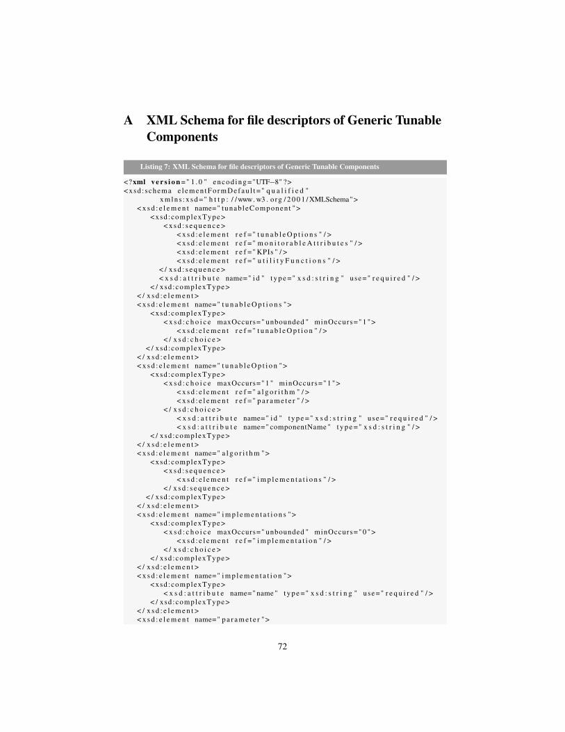
A XML Schema for file descriptors of Generic TunableComponents
Listing 7: XML Schema for file descriptors of Generic Tunable Components
<? xml v e r s i o n =" 1 . 0 " e n c o d i n g ="UTF−8" ?>< xsd : schema e l e m e n t F o r m D e f a u l t =" q u a l i f i e d "
x m l n s : x s d =" h t t p : / /www. w3 . org / 2 0 0 1 / XMLSchema">< x s d : e l e m e n t name=" tunab leComponen t ">
< xsd :complexType >< x s d : s e q u e n c e >
< x s d : e l e m e n t r e f =" t u n a b l e O p t i o n s " / >< x s d : e l e m e n t r e f =" m o n i t o r a b l e A t t r i b u t e s " / >< x s d : e l e m e n t r e f =" KPIs " / >< x s d : e l e m e n t r e f =" u t i l i t y F u n c t i o n s " / >
< / x s d : s e q u e n c e >< x s d : a t t r i b u t e name=" i d " t y p e =" x s d : s t r i n g " use =" r e q u i r e d " / >
< / xsd :complexType >< / x s d : e l e m e n t >< x s d : e l e m e n t name=" t u n a b l e O p t i o n s ">
< xsd :complexType >< x s d : c h o i c e maxOccurs=" unbounded " minOccurs=" 1 ">
< x s d : e l e m e n t r e f =" t u n a b l e O p t i o n " / >< / x s d : c h o i c e >
< / xsd :complexType >< / x s d : e l e m e n t >< x s d : e l e m e n t name=" t u n a b l e O p t i o n ">
< xsd :complexType >< x s d : c h o i c e maxOccurs=" 1 " minOccurs=" 1 ">
< x s d : e l e m e n t r e f =" a l g o r i t h m " / >< x s d : e l e m e n t r e f =" p a r a m e t e r " / >
< / x s d : c h o i c e >< x s d : a t t r i b u t e name=" i d " t y p e =" x s d : s t r i n g " use =" r e q u i r e d " / >< x s d : a t t r i b u t e name=" componentName " t y p e =" x s d : s t r i n g " / >
< / xsd :complexType >< / x s d : e l e m e n t >< x s d : e l e m e n t name=" a l g o r i t h m ">
< xsd :complexType >< x s d : s e q u e n c e >
< x s d : e l e m e n t r e f =" i m p l e m e n t a t i o n s " / >< / x s d : s e q u e n c e >
< / xsd :complexType >< / x s d : e l e m e n t >< x s d : e l e m e n t name=" i m p l e m e n t a t i o n s ">
< xsd :complexType >< x s d : c h o i c e maxOccurs=" unbounded " minOccurs=" 0 ">
< x s d : e l e m e n t r e f =" i m p l e m e n t a t i o n " / >< / x s d : c h o i c e >
< / xsd :complexType >< / x s d : e l e m e n t >< x s d : e l e m e n t name=" i m p l e m e n t a t i o n ">
< xsd :complexType >< x s d : a t t r i b u t e name=" name " t y p e =" x s d : s t r i n g " use =" r e q u i r e d " / >
< / xsd :complexType >< / x s d : e l e m e n t >< x s d : e l e m e n t name=" p a r a m e t e r ">
72

< xsd :complexType mixed=" t r u e ">< x s d : s e q u e n c e >
< x s d : e l e m e n t r e f =" Type " / >< x s d : e l e m e n t r e f =" minValue " / >< x s d : e l e m e n t r e f =" maxValue " / >
< / x s d : s e q u e n c e >< / xsd :complexType >
< / x s d : e l e m e n t >< x s d : e l e m e n t name=" Type " t y p e =" x s d : s t r i n g " / >< x s d : e l e m e n t name=" minValue " t y p e =" x s d : d e c i m a l " / >< x s d : e l e m e n t name=" maxValue " t y p e =" x s d : d e c i m a l " / >< x s d : e l e m e n t name=" m o n i t o r a b l e A t t r i b u t e s ">
< xsd :complexType >< x s d : c h o i c e maxOccurs=" unbounded " minOccurs=" 0 ">
< x s d : e l e m e n t r e f =" m o n i t o r a b l e A t t r i b u t e " / >< / x s d : c h o i c e >
< / xsd :complexType >< / x s d : e l e m e n t >< x s d : e l e m e n t name=" m o n i t o r a b l e A t t r i b u t e ">
< xsd :complexType mixed=" t r u e ">< x s d : s e q u e n c e >
< x s d : e l e m e n t r e f =" name " / >< x s d : e l e m e n t r e f =" t y p e " / >< x s d : e l e m e n t r e f =" minValue " / >< x s d : e l e m e n t r e f =" maxValue " / >
< / x s d : s e q u e n c e >< / xsd :complexType >
< / x s d : e l e m e n t >< x s d : e l e m e n t name=" name " t y p e =" x s d : s t r i n g " / >< x s d : e l e m e n t name=" t y p e " t y p e =" x s d : s t r i n g " / >< x s d : e l e m e n t name=" KPIs ">
< xsd :complexType >< x s d : c h o i c e maxOccurs=" unbounded " minOccurs=" 0 ">
< x s d : e l e m e n t r e f =" KPI " / >< / x s d : c h o i c e >
< / xsd :complexType >< / x s d : e l e m e n t >< x s d : e l e m e n t name=" KPI ">
< xsd :complexType >< x s d : s e q u e n c e >
< x s d : e l e m e n t r e f =" r e l e v a n t M o n i t o r a b l e A t t r i b u t e s " / >< x s d : e l e m e n t r e f =" r e l e v a n t T u n a b l e O p t i o n s " / >
< / x s d : s e q u e n c e >< x s d : a t t r i b u t e name=" name " t y p e =" x s d : s t r i n g " use =" r e q u i r e d " / >
< / xsd :complexType >< / x s d : e l e m e n t >< x s d : e l e m e n t name=" r e l e v a n t M o n i t o r a b l e A t t r i b u t e s ">
< xsd :complexType >< x s d : c h o i c e maxOccurs=" unbounded " minOccurs=" 0 ">
< x s d : e l e m e n t r e f =" r e l e v a n t M o n i t o r a b l e A t t r i b u t e " / >< / x s d : c h o i c e >
< / xsd :complexType >< / x s d : e l e m e n t >< x s d : e l e m e n t name=" r e l e v a n t M o n i t o r a b l e A t t r i b u t e ">
< xsd :complexType >< x s d : a t t r i b u t e name=" i d " t y p e =" x s d : s t r i n g " use =" r e q u i r e d " / >< x s d : a t t r i b u t e name=" componentName "
73
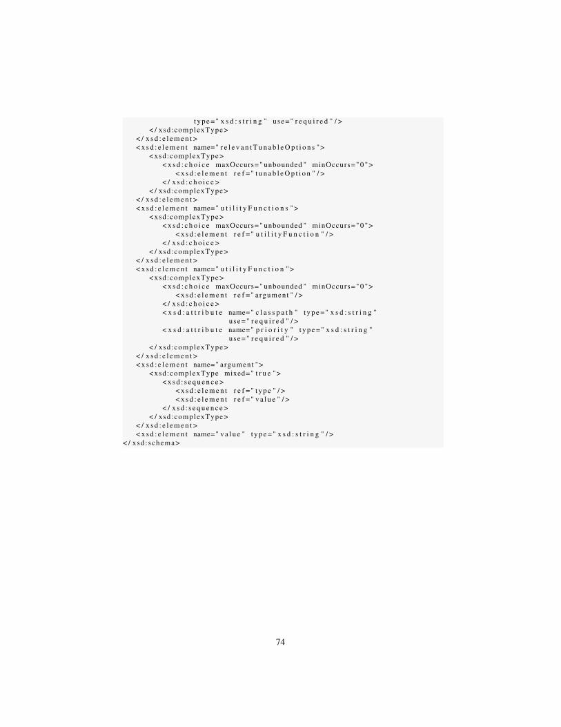
t y p e =" x s d : s t r i n g " use =" r e q u i r e d " / >< / xsd :complexType >
< / x s d : e l e m e n t >< x s d : e l e m e n t name=" r e l e v a n t T u n a b l e O p t i o n s ">
< xsd :complexType >< x s d : c h o i c e maxOccurs=" unbounded " minOccurs=" 0 ">
< x s d : e l e m e n t r e f =" t u n a b l e O p t i o n " / >< / x s d : c h o i c e >
< / xsd :complexType >< / x s d : e l e m e n t >< x s d : e l e m e n t name=" u t i l i t y F u n c t i o n s ">
< xsd :complexType >< x s d : c h o i c e maxOccurs=" unbounded " minOccurs=" 0 ">
< x s d : e l e m e n t r e f =" u t i l i t y F u n c t i o n " / >< / x s d : c h o i c e >
< / xsd :complexType >< / x s d : e l e m e n t >< x s d : e l e m e n t name=" u t i l i t y F u n c t i o n ">
< xsd :complexType >< x s d : c h o i c e maxOccurs=" unbounded " minOccurs=" 0 ">
< x s d : e l e m e n t r e f =" argument " / >< / x s d : c h o i c e >< x s d : a t t r i b u t e name=" c l a s s p a t h " t y p e =" x s d : s t r i n g "
use =" r e q u i r e d " / >< x s d : a t t r i b u t e name=" p r i o r i t y " t y p e =" x s d : s t r i n g "
use =" r e q u i r e d " / >< / xsd :complexType >
< / x s d : e l e m e n t >< x s d : e l e m e n t name=" argument ">
< xsd :complexType mixed=" t r u e ">< x s d : s e q u e n c e >
< x s d : e l e m e n t r e f =" t y p e " / >< x s d : e l e m e n t r e f =" v a l u e " / >
< / x s d : s e q u e n c e >< / xsd :complexType >
< / x s d : e l e m e n t >< x s d : e l e m e n t name=" v a l u e " t y p e =" x s d : s t r i n g " / >
< / xsd : schema >
74