clp-6001/6002 - citizen systems · - iii - important safety instructions 1. read all of these...
TRANSCRIPT

CLP-6001/6002
User’s Manual

- i -
FCC COMPLIANCE STATEMENTFOR AMERICAN USERS
This equipment has been tested and found to comply with the limits for a Class A digitaldevice, pursuant to Part 15 of the FCC Rules. These limits are designed to providereasonable protection against harmful interference when the equipment is operated in acommercial environment. This equipment generates, uses, and can radiate radiofrequency energy and, if not installed and used in accordance with the instruction manual,may cause harmful interference to radio communications. Operation of this equipment in aresidential area is likely to cause harmful interference in which case the user will be requiredto correct the interference at his own expense.
"DESIGNED AND MANUFACTURED TO BE EQUIVALENT TO EUROPEANSTANDARD FOR ITE, EN60950."

- ii -
EMI COMPLIANCE STATEMENTFOR CANADIAN USERS
This equipment generates and uses radio frequency energy and if not installed and usedproperly, that is, in strict accordance with the manufacturer's instructions, may causeinterference to radio and television reception. This digital apparatus does not exceed theClass A limits for radio noise emissions from digital apparatus set out in the Radio InterferenceRegulations of the Canadian Department of Communications. This equipment is designed toprovide reasonable protection against such interference in a residential installation. However,there is no guarantee that interference will not occur in a particular installation. If thisequipment does cause interference to radio or television reception, which can be determinedby turning the equipment off and on, the user is encouraged to try to correct the interferenceby one or more of the following measures:
• Reorient or relocate the receiving antenna.
• Increase the separation between the equipment and receiver.
• Connect the equipment into an outlet on a circuit different from that to which thereceiver is connected.
• Consult the dealer or an experienced radio/TV technician for help.
CAUTION: Use shielded cables to connect this device to computers.
Any changes or modifications not expressly approved by thegrantee of this device could void the user's authority tooperate the equipment.
ETAT DE CONFORMITE EMI A L'USAGEDES UTILISATEURS CANADIENS
Cet équipment produit et utilise l'énergie à radiofréquences et s'il n'est pas installé et utilisécorrectment, c'esst à dire en accord strict avec les instructions du fabricant, il risque deprovoquer des intérferences avec la réception de la radio et de la télévision.
Le présent appareil numérique n'émet pas de bruite radioélectriques dépassant les limitesapplicables aux appareils numériques de la classe A prescrites dans le Réglement sur lebrouillage radioélectrique édicté par le ministère des Communications du Canada.
Cet équipment est conçu pour fournir une protection satisfaisante contre de tellesinterférences dans une installation résidentielle. Cependant, il n'y a pas de garantie contreles interférences avec les réceptions radio ou télévison, provoquées par la mise en et horscircuit de l'équipment; aussi, il est demandé a l'utilisateur d'essayer de corriger l'interférencepar l'une ou plus des mesures suivantes:
• Réorienter l'antenne de réception.
• Installer l'ordinateur autre part, par égard pour le récepteur.
• Brancher l'ordinateur dans une prise de courant différente de façon à ce quel'ordinateur et le récepteur soient branchés sur des circuits différents.

- iii -
Important Safety Instructions
1. Read all of these instructions and save them for later reference.
2. Follow all warnings and instructions marked on the product.
3. Unplug this product from the wall outlet before cleaning. Do not use liquid or aerosolcleaners. Use a damp cloth for cleaning.
4. Do not use this product near water.
5. Do not place this product on an unstable ca rt, stand or table. The product may fall, causingserious damage to the product.
6. Slots and openings on the cabinet and the back or bottom are provided for ventilation.
To ensure reliable operation of the product and to protect it from overheating, do not block orcover these openings. The openings should never be blocked by placing the product on abed, sofa, rug or other similar surface. This product should never be placed near or over aradiator or heat register. This product should not be placed in a built-in installation unlessproper ventilation is provided.
7. This product should be operated from the type of power source indicated on the markinglabel. If you are not sure of the type of power available, consult your dealer or local powercompany.
8. This product is equipped with a three-pronged plug, a plug having a third (grounding) pin.This plug will only fit into a grounding-type power outlet. This is a safety feature. If youare unable to insert the plug into the outlet, contact yourelectrician to replace your obsoleteoutlet. Do not defeat the safety purpose of the grounding-type plug.
9. Do not allow anything to rest on the power cord. Do not locate this product where the cordwill be walked on.
10. If an extension cord is used with this product, make sure that the total of the ampere ratingson the products plugged into the extension cord do not exceed the extension cord ampererating. Also, make sure that the total of all products plugged into the wall outlet does notexceed 15 amperes for 120V outlet and 7.5 amperes for 220 −240V outlet.
11. Never push objects of any kind into this product through cabinet slots as they may touchdangerous voltage points or short out parts that could result in a risk of fire or electric shock.Never spill liquid of any kind on the product.
12. Except as explained elsewhere in this manual, don't attempt to service this product yourself.Opening and removing those covers that are marked "Do Not Remove" may expose you todangerous voltage points or other risks. Refer all servicing on those compartments toservice personnel.
13. The mains plug on this equipment must be used to disconnect mains power. Pleaseensure that the socket outlet is installed near the equipment and shall be easily accessible.
14. Unplug this product from the wall outlet and refer servicing to qualified service personnelunder the following conditions:
A. When the power cord or plug is damaged or frayed.
B. If liquid has been spilled into the product.
C. If the product has been exposed to rain or water.
D. If the product does not operate normally when the operating instructions are followed.Adjust only those controls that are covered by the operating instructions sinceimproper adjustment of other controls may result in damage and will often requireextensive work by a qualified technician to restore the product to normal operation.
E. If the product has been dropped or the cabinet has been damaged.
F. If the product exhibits a distinct change in performance, indicating a need forservice.

- iv -
Notice
1. Before use, be sure to read this manual. And keep it handy forreference when needed.
2. The contents of this manual may be changed without prior notice.
3. Reproduction, transfer, or transmission of the contents of this manualwithout prior consent is strictly prohibited.
4. We are not liable for any damage resulting from the use of theinformation contained herein, regardless of errors, omissions, ormisprints.
5. We are not liable for any problems resulting from the use of optionalproducts and consumable supplies other than the designatedproducts contained herein.
6. Do not handle, disassemble or repair the parts other than thosespecified in this manual.
7. We are not liable for any damage caused by user's erroneous use ofthe printer and inadequate environment.
8. Data residing in the printer is temporary. Therefore, all data will belost if power is lost. We are not liable for any damage or loss ofprofits caused by data loss due to failures, repairs, inspections, etc.
9. Please contact us if there are any mistakes or ambiguities within thismanual.
10. If there are missing or incorrectly collated pages in this manual,contact us to obtain a new manual.
Trademarks or registered trademarks of other companies and productsare included in this manual.
CE marking shows conformity to the following criteria and provisions:
Low Voltage Directive (73/23/EEC)/EN60950
EMC Directive (89/336/EEC)/EN55022 & EN50082-1

- v -
To prevent personal injury or property damage, the following shall be strictlyobserved.
The degree of possible injury and damage due to incorrect use or improperlyfollowing instructions is described below.
This is a mark to call attention to the reader.
SAFETY SIGNS must be strictl y observed !
WARNING Indicates a situation which, if not observedand handled properly, could result in deathor serious injury.
CAUTION Indicates a situation which, if not observedand handled properly, could result in injury.

- vi -
WARNING
Never perform the following. If not avoided, these may cause damageor trouble to the printer or cause the printer to overheat and releasesmoke and cause burns or an electrical shock. If the printer isdamaged or is malfunctioning, be sure to turn the power off and removethe power cord from the outlet, then consult our service personnel.
• Do not jolt or impact to the printer by stepping on, dropping or hittingthe printer.
• Do not place the printer in a poorly ventilated area, or shut off the airvent of the printer.
• Do not place the printer where chemical reactions occur, such as inlaboratories or where air is mixed with salt or gas.
• Do not use a power voltage or frequency other than those specified.
• Do not plug/unplug the power cord or attach/detach the interfacecable by simply grabbing the power cord or interface cable. Do notpull or carry the printer when the tension of the power cord orinterface cable is increased.
• Do not drop or put foreign matter such as clips and pins into theprinter. This may cause problems.
• Do not plug the power cord into an outlet with many loads.
• Do not spill drinks such as tea, coffee and juice on the printer or sprayinsecticide on the printer. If drink or water is spilled, first be sure toturn the power off and remove the power cord from the outlet, thenconsult our service personnel.
• Do not disassemble or modify the printer.
Discard or safely store the plastic packing bag. This bag should bekept away from children. If the bag is pulled over child’s head, it maycause suffocation.

- vii -
General Precautions
1. Prior to operation, read the safety instructions carefully and observe them.
2. Be careful when moving or carrying the printer. Dropping the printer maycause injury or property damage.
3. Make sure if you open the top cover, it is opened all the way. If only partiallyopen, the cover could slam shut, possibly causing injury.
4. When the cover is open, be careful of the corners of cover. They couldcause injury.
5. Do not open the printer during printing.
6. When cleaning the surface of the printer case, do not use the cloth that issoaked in thinner, trichloroethylene, benzine, ketone or similar chemicals.
7. Do not use the printer where there is a lot of oil, iron particles, or dust.
8. Operate the control panel properly. A careless, rough handling may causeproblems or malfunction. Do not use such sharp-edged tool as a ballpointfor operation.
9. Before attaching the auto-cutter drive board, be sure to unplug the power cordfrom the outlet.
10. Attaching the auto-cutter drive board must not be done immediately after useof printer.
11. Be careful not to damage the printer's drive pulley and belt.
12. Be careful of the edges of the plates so injury or property damage is possible.
13. If a problem occurs during printing, stop the printer immediately and unplugthe power cord from the outlet.

- viii -
Precautions When Installing the Printer
1. Prior to operation, read the safety instructions carefully and observe them.
2. Do not use or store the printer near fire, excessive moisture, in directsunlight, near an air conditioner or heater or other source of unusually highor low temperature or humidity or excessive dust.
3. Do not place the printer where chemical reactions occur, such as in alaboratory.
4. Do not place the printer where air is mixed with salt or gas.
5. The printer must sit on a firm, level surface where there is ample ventilation.Never allow the printer's air vent to be blocked by a wall or other object.
6. Do not place anything on the top printer.
7. Do not place the printer near a radio or television, and do not use the samewall outlet for the printer and radio or television. Radio or televisionreception could be adversely affected.
8. Do not bundle the power cord when inserting the plug.
9. Grip the plug housing, not the cord, to unplug the power cord.
10. Make certain the interface cable is attached properly. If polarity directionis not correct, this may cause internal damage.
11. Make certain the power is turned off before attaching/detaching theinterface cable.
12. Avoid lengthening the signal cable or attaching it to any noise-producingdevice. If it is unavoidable, use the shielded cable or twisted pair for eachsignal.

- ix -
Chapters in This Manual
Chapter 1 Setup
Describes the packed items after opening the carton aswell as the names and functions of parts.
Chapter 2 Control panel
Describes the necessary items for operations, such asthe control panel, printer settings and indications on theLCD/LEDs.
Chapter 3 Paper and Ribbon
Describes the procedures for loading paper and ribbonand includes notes on the use of paper and ribbons.
Chapter 4 Troubleshooting
Describes corrective actions when problems occur.
Chapter 5 Options
Describes the optional accessories for this printer.
Chapter 6 Specifications
Describes the basic specifications and commands forthis printer.

- x -
Table of Contents
FCC Compliance Statement for American Users..................................i
EMI Compliance Statement for Canadian Users.................................. ii
Important Safety Instructions .............................................................. iiiNotice ................................................................................................. iv
Safety Signs ........................................................................................v
Warning..............................................................................................viGeneral Precautions.......................................................................... vii
Precautions When Installing the Printer ............................................ viii
Chapters in This Manual..................................................................... ix
Chapter 1 Setup .................................................................................. 1-1
1.1 Confirmation of Carton Contents ........................................... 1-2
1.2 Part Names and Functions.................................................... 1-3
1.3 Connection to Power............................................................. 1-71.4 Connection to a Computer .................................................... 1-8
Chapter 2 Control Panel ....................................................................... 2-1
2.1 Control Panel ........................................................................ 2-2
2.2 LCD/LED Indications and Adjustment Controls ..................... 2-32.3 Normal Operating Mode ........................................................ 2-3
2.4 Printer Setup Mode ............................................................... 2-4
2.5 Self-Test Mode ...................................................................... 2-42.6 System Maintenance Mode................................................... 2-5
Chapter 3 Paper and Ribbon................................................................ 3-1
3.1 Kinds of Paper ...................................................................... 3-2
3.2 Specification of Label and Tag............................................... 3-23.3 Ribbon .................................................................................. 3-6
3.4 Paper Setting ........................................................................ 3-7
3.5 Ribbon Setting ...................................................................... 3-93.6 Print Head Offset Adjustments ............................................ 3-10
3.7 Ribbon Tension Adjustments............................................... 3-13
3.8 Paper Detector Adjustments (for CLP-6001 only)................ 3-143.8.1 Exterior view and part names................................... 3-14
3.8.2 How to operate adjustable sensor............................ 3-15

- xi -
(continued)
Chapter 4 Troubleshooting .................................................................. 4-1
4.1 Error Messages..................................................................... 4-2
4.1.1 Error descriptions and indications .............................. 4-2
4.1.2 Error indications and corrective actions...................... 4-44.2 Power Troubleshooting.......................................................... 4-7
4.3 Paper Feed Troubleshooting ................................................. 4-8
4.4 Ribbon Feed Troubleshooting ............................................... 4-94.5 Print Troubleshooting .......................................................... 4-10
4.6 Interface Troubleshooting.....................................................4-11
Chapter 5 Options................................................................................. 5-1
Factory or Reseller (Dealer) Options:5.1 Auto-Cutter Unit .................................................................... 5-2
5.2 Peeler Unit ............................................................................ 5-2
5.3 Adjustable Sensor (for CLP-6002 only) ................................. 5-2
User Options:
5.4 PCMCIA Memory Card.......................................................... 5-3
Chapter 6 Specifications ...................................................................... 6-1
6.1 Main Specifications ............................................................... 6-26.2 Interface................................................................................ 6-6
6.2.1 System configuration............................................................. 6-6
6.2.2 Specification of interface............................................ 6-76.2.3 RS-232C loopback test.............................................. 6-8
6.2.4 RS-232C protocol ...................................................... 6-9
6.2.5 Interface pin assignment...........................................6-116.3 Outline of Command System............................................... 6-13
6.4 Example of Connection to a Computer................................ 6-14
6.5 Tear-Off Function ................................................................ 6-156.5.1 Turning Tear ON/OFF .............................................. 6-15
6.5.2 Tear-off when printing .............................................. 6-15
6.5.3 Tear-off when feeding .............................................. 6-166.5.4 Tear-off and type of data .......................................... 6-17
6.5.5 Cut position adjustments.......................................... 6-17
6.5.6 When "fnnn" command is executedwhile tear-off is OFF................................................. 6-18
6.5.7 Priority order ............................................................ 6-19

- xii -

1-1
Chapter 1Setup
1.1 Confirmation of Carton Contents ........................... 1-2
1.2 Part Names and Functions.................................... 1-3
1.3 Connection to Power ............................................. 1-7
1.4 Connection to a Computer..................................... 1-8

1-2
1.1 Confirmation of Carton Contents
CAUTION Be careful when moving or carrying the printer andwhen taking the printer out of the carton. The printermay cause injury or property damage if dropped. Besure to grip the printer housing tightly when taking itout of the carton. Do not grip the styro-foam to theprinter which may break, causing the printer to drop.
Check that all the following accessories are included with the printer in the carton.
• Power cord 1 pc
• Roll holder 1 pc
• Roll guide 1 pc
• Paper core 1 pc
• User's manual (this booklet) 1 copy
Note: The empty carton and packing materials should be stored for futureshipping of the printer.
Printer User’s manual
Power cord
Paper core
Roll holder
Roll guide

1-3
1.2 Part Names and Functions
FRONT VIEW
Control panel
The printer has two LED indicator lights and an LCD screen that displaysprinter messages.
1) LEDs
One LED is the power indicator and the other is the error indicator.
2) LCD
Displays the current printer status, configuration settings, or anerror message.
3) Control keys
The Pause, Feed and Stop keys are arranged from left to right andare used to facilitate printer operating. (For details, see Chapter 2Control Panel.)
4) Cover hinges
The cover hinges are used to hold the cover as far as you haveopened it.
Hinge
LCD
LEDs
Control keys

1-4
INSIDE VIEW
Ribbon winder
Open lever
Offset verification window
Ribbon holder
Paper holder
Roll guide
Roll holder
Cover

1-5
Names and functions of each part
CAUTION • When opening the cover, open it all the way.If only part way open, the cover could slam shut,possibly causing injury.
• Be careful of the edge of the cover when the coveris opened. It may cause injury or propertydamage.
• Be careful of the edges of the plates so injury orproperty damage is possible.
1) Cover
Opens to allow loading of the paper and ribbon.
2) Ribbon holder
To attach the ribbon. (See Chapter 3 Paper and Ribbon.)
3) Ribbon winder
To wind the ribbon. (See Chapter 3 Paper and Ribbon.)
4) Roll holder
Holds the roll of paper.
5) Roll guide
Guides the roll paper to be set on the roll holder. The roll guide can beadjusted in accordance with the width of the paper.
6) Paper holder
Holds the roll holder which is inserted in the paper core.
7) Open lever
To swing the print head out of the way when loading the paper or cleaningthe print head.
8) Offset verification window
Allows you to check the position of the print head which must be adjusted tothe thickness of the paper used. (See Chapter 3 Paper and Ribbon.)

1-6
SIDE VIEW
Interface connector
To connect the interface cable.
PCMCIA memory card cover
To protect the PCMCIA memory card from exposure to dust and foreignmatter. To install a PCMCIA memory card, first unhook this cover, thenslide it out.
Power switch
To turn on/off the power.
Power inlet
To connect the power cord.
PCMCIA memory card cover Parallelinterfaceconnector
Serialinterfaceconnector
Power inlet
Powerswitch

1-7
1.3 Connection to Power
CAUTION Use an AC outlet that accepts a three-pronged plug.Otherwise, static electricity may be generated andthere will be danger of electric shock.
Connect to an AC outlet as follows:
1 Check that the power switch on the printer is set to OFF.
2 Connect the connector of the power cord to the power inlet on the printer.
3 Insert the plug of the power cord in the AC outlet.
Power inlet
Power switch
AC outlet

1-8
1.4 Connection to a Computer
An interface cable is necessary for connecting the printer to a computer.
To connect them, proceed as follows:
1 Turn off both power switches of the printer and the computer.
2 Connect the connector of one end of the interface cable to the interfaceconnector at the lower side of the printer and secure it with screws.
3 Connect the connector of the other end of the interface cable to the interfaceconnector on the computer and secure it with screws.
To a computer

2-1
Chapter 2Control Panel
2.1 Control Panel ...................................................... 2-2
2.2 LCD/LED Indications and Adjustment Controls ... 2-3
2.3 Normal Operating Mode...................................... 2-3
2.4 Printer Setup Mode ............................................. 2-4
2.5 Self-Test Mode.................................................... 2-4
2.6 System Maintenance Mode................................. 2-5

2-2
2.1 Control Panel
The control panel on the front of the printer consists of three control keys(Pause, Feed and Stop), two LED indicator lights (Power, Error) and a LCDmessage screen. On the left side of the control panel there are threeadjustment controls (paper gap, black line and LCD contrast).
1 Exterior view
The exterior view of the control panel is shown below.
Serial interface connector
Parallel interface connector
Paper gap adjustment control
Black line adjustment control
LCD contrast adjustment control
Pause key
Feed key
Stop key
LCD
LED power indicator
LED error indicator
Power switch
Power inlet

2-3
2.2 LCD/LED Indications and Adjustment Controls
1 LCD
The eight-character LCD screen displays the current printer status,configuration settings, or an error message.
2 LEDs
Power: The green LED power indicator goes on when the power is tuned ON.
Error: The red LED error indicator goes on when an error occurs.
3 Adjustment controls
The three adjustment controls are used to adjust the paper gap (transparenttype) sensor sensitivity, black line (reflective type) sensor sensitivity, and LCDcontrast.
2.3 Normal Operating Mode
When the power is turned on, the printer enters normal operating mode.
The control keys function as follows:
Pause key
Temporarily pauses printing. "Pause" is displayed on the LCD screen.If pressed during printing, printing will stop after the current label is printed.Press the Pause key again to resume printing.
Feed key
Advance to the top of the next label. When using continuous paper, makesure the Sensor selection is set to ContinuP or a Paper error will result.
Stop key
With this key, the operator can stop and cancel the current print job. Pressingthe Stop key during printing stops the printing immediately. Pressing the Stopkey again cancels the print job.

2-4
2.4 Printer Setup Mode
To enter the printer setup mode, press and hold down the Pause then press theFeed key and release both keys. The functions of the control keys are describedbelow.Changes to the printer configuration are stored in nonvolatile memory. Thisguarantees that the printer configuration is maintained even after the power isturned off.
[Functions]
Print mode selection, peeling sensor ON/OFF, auto-cutter ON/OFF, etc.
Pause key: Selects the mode.
Feed key: Selects the mode item.
Stop key: Saves the selection contents and returns the printer to thenormal operating mode.
Mode item Indication
2.5 Self-Test Mode
The printer enters the self-test mode when the Feed key is pressed and held downwhile turning the printer on.
[Functions]
The printer performs the test print or enters the data dump mode (prints out thecommunication data by ASCII code). The printer returns to the normal operatingmode when the power is turned off.

2-5
2.6 System Maintenance Mode
The printer enters the system maintenance mode when the Pause, Feed and Stopkeys are pressed and held down simultaneously while turning the printer on.
[Functions]
Holding down the Pause, Feed and Stop keys simultaneously for more than fourseconds after turning on the power allows the memory switches to be set to defaultvalues (*).
The printer enters the communication parameter setting and paper gap and blackline sensor sensitivity adjusting mode.
The mode is selected with the Pause key and the mode item is selected with theFeed key. Changing of the contents is executed as soon as they are displayed onthe screen.
Pressing the Stop key returns the printer to the normal operating mode.
Pause: Mode selection
Feed key: Item selection
Mode item Indication
* Default values
Baud rate: 9600 bpsRS-232C setting
Data length
Print mode setting Transfer
Peeling: OFF
Auto-cutter: OFF
Optional functions
Tear-off: OFF
Paper sensor setting Edge
Model Native ON

2-6
Voltage setting mode
In the voltage setting mode, operate the paper gap and black line adjustmentcontrols so that the voltages of both "PE" and "BL" displayed on the LCD screenread 3.0 V−3.3 V.
Setting procedure:
1 Sets only the liner (glassine paper) that has been peeled off the label paper.
2 Sets the paper gap level to 3.0 V−3.3 V (paper gap comes first).
3 Sets the black line level to 3.0 V−3.3 V (then black line).
Note: The order of steps 2 and 3 above may be reversed.
3-1
Chapter 3Paper and Ribbon
3.1 Kinds of Paper .................................................... 3-2
3.2 Specification of Label and Tag............................. 3-2
3.3 Ribbon ................................................................ 3-6
3.4 Paper Setting ...................................................... 3-7
3.5 Ribbon Setting .................................................... 3-9
3.6 Print Head Offset Adjustments .......................... 3-10
3.7 Ribbon Tension Adjustments............................. 3-13
3.8 Paper Detector Adjustments ............................. 3-14
3.8.1 Exterior view and part names................... 3-14
3.8.2 How to operate adjustable sensor............ 3-15

3-2
3.1 Kinds of Paper
1 Kinds of paper
Direct-thermal or thermal-transfer printing paper is available. The papermust be high-quality. Otherwise, print quality and long life of print headwill not be guaranteed.
2 Type of paper
• Label (continuous, die-cut, fanfold)
• Tag
• Ticket
The roll paper with inking surface either rolled inward or outward may beused.
3 Size of paper
Paper width: 25.4 mm−118 mm (1 in−4.65 in)
Paper thickness: 0.063 mm−0.254 mm (0.0025 in−0.01 in)
Max. printing width: 104 mm (4.1 in)
Max. printing length: 406 mm (16 in)
Max. outer diameter of roll paper: 203 mm (8 in)
4 Paper core inner diameter
38 mm−76 mm (1.5 in−3 in)
3.2 Specification of Label andTag
The position of a label or tags is detected by the printer's transparent-typeand reflective-type photosensors.
Transparent-type photosensor: Detects paper gap between label andtag notch.
Reflective-type photosensor: Detects black line.
Specification of paper
For each dimension of paper gap between labels, tag (label) notch and blackline, see the figure. The black line must be aligned with the top edge ofeach label.

3-3
Unit: mm (inch)
CLP-6001 CLP-6002
Min. value Max. value Min. value Max. value
A Label width 25.40 (1.0) 118.00 (4.65) 25.40 (1.0) 118.00 (4.65)
B Liner width 25.40 (1.0) 118.00 (4.65) 25.40 (1.0) 118.00 (4.65)
C Label left-side edge position 0 2.54 (0.10) 0 2.54 (0.10)
D Label paper-gap length 2.54 (0.10) 2539.00 (99.96) 2.54 (0.10) 2539.00 (99.96)
E Label length 12.70 (0.50) 2539.00 (99.96) 12.70 (0.50) 2539.00 (99.96)
F Label pitch 12.70 (0.50) 2539.00 (99.96) 12.70 (0.50) 2539.00 (99.96)
G Liner thickness 0.06 (0.0025) 0.125 (0.0049) 0.06 (0.0025) 0.125 (0.0049)
H Paper thickness 0.06 (0.0025) 0.25 (0.01) 0.06 (0.0025) 0.25 (0.01)
I Notch right-side edge position 3.6 (0.14) 60.8 (2.39) 8.3 (0.32) 11 (0.43)
J Notch left-side edge position 0 57.2 (2.25) 0 4.7 (0.19)
K Notch length 2.54 (0.10) 17.80 (0.70) 2.54 (0.10) 17.80 (0.70)
L Black line right-side edge position 15.00 (0.59) 15.00 (0.59)
M Black line left-side edge position 0 51.5 (2.02) 0 1.5 (0.06)
N Black line width 3.18 (0.125) 17.80 (0.70) 3.18 (0.125) 17.80 (0.70)
Note: • If paper has both label paper-gap and black-line, choose the paper-gap sensor.• Fanfold uses the paper-gap sensor.
Size of paper
Printing area
Direction of paper feed
Black-line (back)OD value: 1.5 or
moreInk containing
carbon
Printingarea
Label Continuous paper
Notch detection Black-line detection
Use of paper-gap sensor Use of paper-gap sensor Use of black-line sensor
H
G
BA
C
I
I
L
M
J
FD
E
KK
N
2.5mm 104.0mm (11.5mm)
Left-sidemargin
Paper specification
Printing area Right-sidemargin
3-4
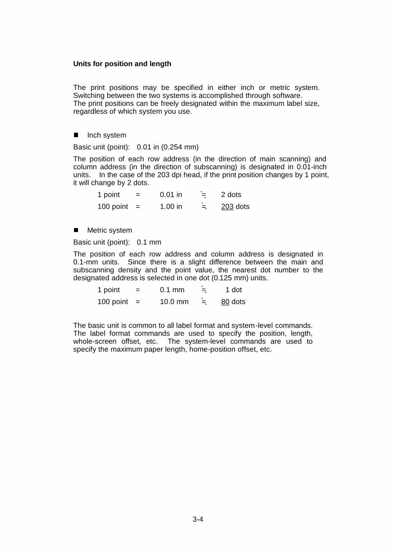
Units for position and length
The print positions may be specified in either inch or metric system.Switching between the two systems is accomplished through software.The print positions can be freely designated within the maximum label size,regardless of which system you use.
Inch system
Basic unit (point): 0.01 in (0.254 mm)
The position of each row address (in the direction of main scanning) andcolumn address (in the direction of subscanning) is designated in 0.01-inchunits. In the case of the 203 dpi head, if the print position changes by 1 point,it will change by 2 dots.
1 point = 0.01 in = 2 dots
100 point = 1.00 in = 203 dots
Metric system
Basic unit (point): 0.1 mm
The position of each row address and column address is designated in0.1-mm units. Since there is a slight difference between the main andsubscanning density and the point value, the nearest dot number to thedesignated address is selected in one dot (0.125 mm) units.
1 point = 0.1 mm = 1 dot
100 point = 10.0 mm = 80 dots
The basic unit is common to all label format and system-level commands.The label format commands are used to specify the position, length,whole-screen offset, etc. The system-level commands are used tospecify the maximum paper length, home-position offset, etc.
. .
. .
. .
. .

3-5
Reference line and points
The reference line and points are described here. The position of 2.5mm from the left edge of the paper is the reference line for paper.Always the left bottom is the reference point for printing characters andbar codes. The concept of this reference line and points are common tosuch commands as ruled line and graphic.
Direction of paper feed
Printing reference point Printing reference point
Paper reference line
Printing reference point Printing reference point
2.5
Left edge of paper

3-6
3.3 Ribbon
Size of ribbon
Width of ribbon: 25.4 mm−114.3 mm (1 in−4.5 in)
The width of the ribbon for thermal-transfer printing is recommended to be the±10% of the width of thepaper .
The inner diameter of the ribbon core must not exceed 25.4 mm (1 in).
The ribbon with inking surface either rolled inward or outward may be used.
The maximum outer diameter of the roll ribbon is 74 mm (2.91 in).
A single roll of the ribbon (360 m) enables the printing of about two rolls of thepaper with outer diameter of 203 mm (8 in).

3-7
3.4 Paper Setting
CAUTION Be careful of the edges of the plates so injury orproperty damage is possible.
The printer is designed for easy loading of paper and ribbon. After opening thecover, set the register paper as follows:
1 Push down the open lever 1 to move the print head out of the way.
2 Push down the lever 3 to move the sensor arm 2 out of the way.
3 Attach the roll paper and roll guide 5 to the roll holder and position it in thepaper holder 6 . After installing the roll paper, adjust the roll guide 5 to thewidth of the roll paper. The roll paper should be in its deepest position(reference side).
4 Pull the moving paper guide 7 toward you to maintain the paper insertionpath.
5 Set the roll paper as shown in the figure.
6 Attach the left side of roll paper to the fixed paper guide 8 and let the movingpaper guide 7 slightly contact the other end of the roll so that the paper doesnot skew.
7 Push down the sensor arm 2 until the lever hook is locked.
8 Align the paper with the positioning notch of the peeling-off plate 9 and thenpress down the ribbon bearing flat 10 to close the print head. The openlever hook will lock.
9 Close the cover.
10 Turn on the power to the printer. The LCD screen on the control panel willdisplay "On line." Press the Feed key. The paper will advance to the nextlabel and stop there.
(For encircled numbers, see figures on the next page.)

3-8
Roll paper
Notch for alignment
Reference side
Roll paper
1
102
5
4
6
3
10
1
5
4
6
3
7
9
8

3-9
3.5 Ribbon Setting
CAUTION Be careful of the edges of the plates so injury orproperty damage is possible.
After opening the cover, set the ribbon as follows:
1 Push down the open lever 1 to move the print head out of the way.
2 Insert the ribbon shaft 11 in the roll ribbon so that it is in its deepest position.Then set it in the ribbon holder as shown in the figure.
3 Insert the ribbon shaft 12 in the paper core 13 so that it is in its deepestposition. Then set it in the ribbon winder as shown in the figure.
4 Adhere the top end of the ribbon to the paper core with adhesive tape. Turnthe ribbon winder in the direction ribbon winding to remove slackness andwrinkles from the ribbon.
5 Press down the ribbon bearing flat 10 to close the print head.The open lever hook will lock.
6 Close the cover.
7 Turn on the power to the printer. The LCD screen on the control panel willdisplay "On line." Press the Feed key. The paper will advance to the nextlabel and stop there.
Ribbon
Print head opened
Roll paper
RibbonDirection of ribbon winding
Completion of setting paper and ribbon
11
12
13
1

3-10
3.6 Print Head Offset Adjustments
CAUTION Ensure the print head offset adjustments are madeproperly according to the type of print media (thickness &width). Incorrect adjustments can cause failure of theprint head.
The printer has already been factory set with labels 118 mm in width. However,the print head offset adjustments may be needed depending on the width of thepaper and the paper quality. If the print quality is inferior because of the paper,adjust it according to the following:
1 When print is unclear or blurred because of poor paper quality:
Adjust the offset between the print head and the platen by turningthe offset adjustment screw. The print head offset adjustments aremade by changing the inclination of the print head to the platen.This has already been factory set, but the offset may need changingif the print head was replaced or disassembled. Also, it may needchanging if a different type of paper was used. In those cases,make adjustments according to the criteria below.
a) Standard paper, label paper (slick paper, craft paper, etc.),and thermal paper
b) Thick paper (tag or other similar paper)
Offset verification window
Offset adjustment screw (M3)

3-11
The relationship between the offset adjustment screw and the print headheating element is shown below:
2 When print darkness on the left and right sides of the label is not equal:
Adjustments may be needed if paper with different width is used. Printdarkness is affected by the amount of pressure on the print head so itmust be adjusted with the head pressure adjustment screw if necessary.
The pressure on the right side of the print head, viewed from the frontpanel, is adjusted by turning the head pressure adjustment screw.
Turning the screw clockwise decreases the pressure, and turning thescrew counterclockwise increases the pressure.
The condition of the right side of the print head can be checked throughthe upper frame window, which is located at the front of the printermechanism unit.
a) Print head position for labelOffset adjustment screw
Offset verification window
b) Print head position for tag
Heating element
Heating element
Offset adjustmentscrew Offset verification window
a
b

3-12
Adjustments
Normally, the pressure on the left and right sides of the print head has alreadybeen adjusted to equal loads at the factory. The check marks are locatedunder the upper frame window.
Adjustments are needed in the following cases:
1) When print on the left side is too light:
Turn the head pressure adjustment screw clockwise.
2) When print on the right side is too light:
Turn the head pressure adjustment screw counterclockwise.
3) When paper of smaller width is used:
In this case, the contact between the print head and the platen becomeslarge, so the stepping motor will have a heavy load or the print head mayscrape the platen. To avoid this, turn the head pressure adjustment screwclockwise to decrease the pressure on the right side of the print head.
In addition, adjustments will be useful for avoiding wrinkling of the ribbon orskewing of the paper. For more information, contact our servicepersonnel.
Verificationwindow
Paper width Right headpressure
1 inch 0 kgf
2 inches 0.5 kgf
3 inches 1 kgf
4 inches 2.4 kgf
Used for adjustments whenribbon wrinkles or skews withpaper width of 4 inches
Factory setting
Head pressure adjust-screw
Upper frame window
Note: These values are just for reference.

3-13
3.7 Ribbon Tension Adjustments
When the ribbon slips or wrinkles during printing, adjust the ribbon tension. Theprinter has already been factory set with the ribbon width of 114 mm. When usingribbon with a different width, adjust it according to the following procedure:
a) Hold the ribbon roll with one hand so that it does not turn.
b) Slightly push the knob toward the ribbon roll with the other hand and rotate theknob until the stopper comes to the desired position.
c) Gradually release the knob so that the stopper fits in the groove on the knob.
Set values to each ribbon width:
Ribbon width Ribbon windingsection
Ribbon feedsection Tension
Adjustment when ribbon slips 5 5 Mild25.4 mm (1 in) 4 450.8 mm (2 in) 3 3
76.2 mm (3 in) 2 2101.6 mm (4 in): factory setting 1 1 Strong
d) After printing, check for ribbon wrinkle or slipping. If it occurs, adjust it furtheraccording to the following procedure:
(1) When the ribbon wrinkles, the tension on the ribbon winding sectionshould be increased.
(2) When the ribbon slips, the tension on the ribbon feed section should bedecreased. If the problem is not resolved even when the tension onthe ribbon feed section is set to 3, the tension on the ribbon windingsection should be increased.
If ribbon problems are not resolved, consult our service personnel.
Ribbon feed section
Ribbon winding sectionVariable knob
Mild
Mild
Strong
Strong

3-14
3.8 Paper Detector Adjustments (for CLP-6001 only)
3.8.1 Exterior view and part names
Exterior view and part names
Adjust-knob
Mark (Yellow) Guide rail upper
37.7
70.6
192.4

3-15
3.8.2 How to operate adjustable sensor
(1) Move the adjustable sensor unit to your required position to detect by turningthe adjust-knob. First measure the position to detect, then align the mark ofthe measure on the guide rail upper with the sensor position mark (yellow) onthe upper sensor to set to the position to detect.
The sensor movable range is shown below.
(2) Load the liner and close the guide rail upper and set voltage to3V.
Note: For voltage setting, see the User’s Manual of the printer.
Sensor movable range
Left-side edge of paper
0 mm118 mm (max. width of paper)
59 mm (sensor movable range

3-16

4-1
Chapter 4Troubleshooting
4.1 Error Messages................................................... 4-2
4.1.1 Error descriptions and indications ............ 4-2
4.1.2 Error indications and corrective actions ... 4-4
4.2 Power Troubleshooting ....................................... 4-7
4.3 Paper Feed Troubleshooting ............................... 4-8
4.4 Ribbon Feed Troubleshooting ............................. 4-9
4.5 Print Troubleshooting ........................................ 4-10
4.6 Interface Troubleshooting.................................. 4-11

4-2
4.1 Error Messages
When there is a problem with the printer, a buzzer sounds, and the error lamp onthe control panel lights and an error message is displayed on the LCD screen.
Error descriptions and corrective actions are shown below.
4.1.1 Error descriptions and indications
Description Indication LED Buzzer
Battery dead (for clock and backup RAM) Battery Lights Sounds long
Low head temperature ColdHead Lights Sounds long
Low PCB temperature Cold PCB Lights Sounds long
Abnormal head resistance valueError contents and head informationrepeatedly displayedRank: Rank of head resistance valueAverage: Average of resistance values
(A/D reading value decimalsystem)
Maximum: Max. value of resistanceMinimum: Min. value of resistance
Head Err
Rank ***Ave.***
Max.***Min.***
Lights Sounds long
Communication error (receive buffer overrun) OverFlow Lights Sounds long
Communication error (parity, framing) S/I Err Lights Sounds long
Communication error (transmit buffer overflow) HostBusyT.D.Full
Blinks Sounds short3 times
Pause key pressed Pause − − − −Pause command reception (remote control) Pause − − − −Head overheat OverHeat
CoolingBlinks Sounds short
3 times
Stop key pressed Stop − − Sounds short3 times
Stop command reception (remote control) Cancel − − − −Mechanism head open HeadOpen Lights Sounds short
3 times
Paper end (no paper left) PaperEnd Lights Sounds short3 times

4-3
Description Indication LED Buzzer
Paper out (paper position can't be detected)
Error contents and sensor informationrepeatedly displayed
M command: Sets length for detectionmiss checking with systemcommand M
Maximum: Max. value of sensorreading voltage
Minimum: Min. value of sensorreading voltage
PaperErr
M CMND
Max*.**V
Min*.**V
Lights Sounds short3 times
Ribbon end RibonOut Lights Sounds short3 times
PCB overheat(PCB or sensor abnormality)
OverHeat Lights Sounds short3 times
Fan stop Fan stop Blinks Sounds short3 times
Option board abnormality OP Err Lights Sounds short3 times
Auto-cutter abnormality(such as poor engagement)
Cut Err Lights Sounds short3 times
ROM checksum error ROM Err Lights Sounds long
RAM checksum error RAM Err Lights Sounds long

4-4
4.1.2 Error indications and corrective actions
Indication Description Corrective actions
Battery Battery dead Automatically returned after displaying the errorfor a certain time.
Change the lithium battery (CR2032).Note: Contact our service personnel toreplace the battery.
If the battery runs down, the realtime clock willstop and the contents of the memory switch willbe lost.
ColdHead Low head temperature Automatically returned after displaying the errorfor a certain time.
Raise the temperature around the printer.
Print density becomes low and print qualitybecomes inferior when the head temperatureis low.
Cold PCB Low PCB temperature Automatically returned after displaying the errorfor a certain time.
Raise the temperature around the printer.
Print density becomes low and print qualitybecomes inferior when the head temperatureis low.
Head Err Abnormal headresistance value
Check the contents and clear with the Stop key.
Replace the print head.
Print quality is affected at the section where thehead resistance value is abnormal.
OverFlow Communication error(receive bufferoverrun)
Check the contents and clear with the Stop key.
Correct the communication control system orcommunication cable failure.
S/I Err Communication error(parity, framing)
Check the contents and clear with the Stop key.
Correct the communication parameter orcommunication cable failure.
HostBusyT.D.Full
Communication error(transmit bufferoverflow)
Automatically returned if the computer receivesdata and the buffer becomes empty.
Pause Pause key pressed Press the Pause key once again to resumeprinting.
If the Stop key is pressed, the stored printingcontents will be lost and "on line" will turn on.
Pause Pause commandreception(communicationcontrol)
Same as above.

4-5
Indication Description Corrective actions
OverHeatCooling
Head overheat Wait until the head temperature goes down.When the temperature becomes low, theremaining printing resumes.
Stop Stop key pressed Enters a pause after displaying the stop by theStop key.
If the Pause key is pressed, the printing willresume.
If the Stop key is pressed again, the storedprinting contents will be lost and "on line" willturn on.
Cancel Stop commandreception(communicationcontrol)
Displays the stop by the stop command,discards the stored printing contents, andenters a pause.
If the Pause key is pressed, "on line" will turnon.
HeadOpen Mechanism headopen
Close the mechanism head.
PaperEnd Paper end (no paperleft)
Install the paper.
PaperErr Paper out (paperposition can't bedetected)
Check the contents and clear with the Stopkey.
Correct the faulty setting of the paper detection(paper gap, black line, continuous paper).
Correct the faulty parameter for paper (max.length, continuous paper).
Adjust the sensor or change for the paper thataccepts the paper position detection.
Specify the length for detection miss checkingwith the M command.
When the paper position can't be detectedduring paper feeding by the specified length, itis judged error. Generally specify the lengthabout three times the label length.
In case of the continuous paper, specify thelabel length with the C command.
Difference between the maximum andminimum values of the sensor reading voltagemust be 0.8 V or more.
Sensor adjustments and paper characteristicverification (voltage verification) can beperformed with the Maintenance mode.

4-6
Indication Description Corrective actions
RibonOut Ribbon end Check the contents and clear with the Stopkey.
Install the ribbon.
Check that the ribbon winds fully.
Correct the faulty setting of the print mode(direct-thermal or thermal-transfer).
OverHeat PCB overheat Turn off the power and reset the printer.If this recurs, contact our service personnel.
Fan stop Fan stop Check for the fan stop caused by the problemssuch as foreign matter entered in the air vent.
Automatically returned if the fan turns again.
If disassembling is needed to remove foreignmatter or the problem can't be identified,contact our service personnel.
OP Err Option boardabnormality
Turn off the power and reset the printer.If this recurs, contact our service personnel.
Cut Err Auto-cutterabnormality (such aspoor engagement)
Check the contents and clear with the Stopkey.
If this can't be cleared, turn off the power andremove foreign matter from the auto-cutter.
If this recurs, contact our service personnel.
ROM Err ROM checksum error Turn off the power and reset the printer.If this recurs, contact our service personnel.
RAM Err RAM checksum error Turn off the power and reset the printer.If this recurs, contact our service personnel.
− − System error (such astimer or CPUmalfunction)
First protect the system, then reset the printer.
4-7
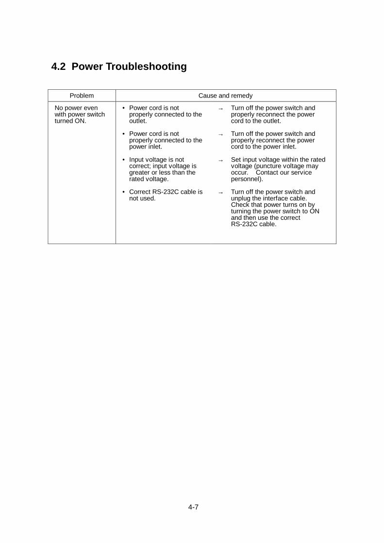
4.2 Power Troubleshooting
Problem Cause and remedy
No power evenwith power switchturned ON.
• Power cord is notproperly connected to theoutlet.
• Power cord is notproperly connected to thepower inlet.
• Input voltage is notcorrect; input voltage isgreater or less than therated voltage.
• Correct RS-232C cable isnot used.
→ Turn off the power switch andproperly reconnect the powercord to the outlet.
→ Turn off the power switch andproperly reconnect the powercord to the power inlet.
→ Set input voltage within the ratedvoltage (puncture voltage mayoccur. Contact our servicepersonnel).
→ Turn off the power switch andunplug the interface cable.Check that power turns on byturning the power switch to ONand then use the correctRS-232C cable.

4-8
4.3 Paper Feed Troubleshooting
Problem Cause and remedy
Paper doesn'tfeed.
• Wrong paper path.
• Mechanism head is open.
→ Use correct path.
→ Close the mechanism head.
Paper skews. • Paper end is not incontact with the paperguide.
• Roll guide is not incontact with the rollpaper.
• Head pressure is notcorrect.
→ Slightly push the paper guideagainst the paper end.
→ Slightly push the roll guideagainst the roll paper.
→ Adjust it with the offset adjustmentscrew according to the paperwidth.
Paper doesn'talign with the printposition.
• Setting mode is notcorrect.
• Paper gap (black line)sensor adjustment failure.
• Transfer data is abnormal.
→ Check whether the setting modeis for paper gap or black linesensor and if it is not, change it asnecessary.
→ Adjust the voltage of the papergap and black line sensor fromthe voltage setting in the systemmaintenance mode.
→ If the contents of the transfer dataare incorrect, set them properlyagain.

4-9
4.4 Ribbon FeedTroubles hooting
Problem Cause and remedy
Ribbon doesn'twind.
• Print mode is set todirect-thermal printing.
• Wrong ribbon path.
• Ribbon wind direction isreversed.
• Ribbon wind tension isnot correct.
→ Change to the thermal-transferprinting.
→ Use correct path.
→ Set it properly.
→ Set it properly.
Ribbon wrinkles. • Tension of ribbon holderand ribbon winder is notcorrect.
• Print density (heatingfactor) is not correct.
• Angle of ribbon guide baris not correct.
→ Set it properly.
→ Correct the parameter of the Hnncommand with the printingcontents definition mode.
→ Contact our service personnel toadjust the ribbon guide bar.
Note: If narrow paper is used, the ribbon may wrinkle. Decreasethe right head pressure by turning the offset adjustment screw toprevent ribbon from wrinkling.
4-10
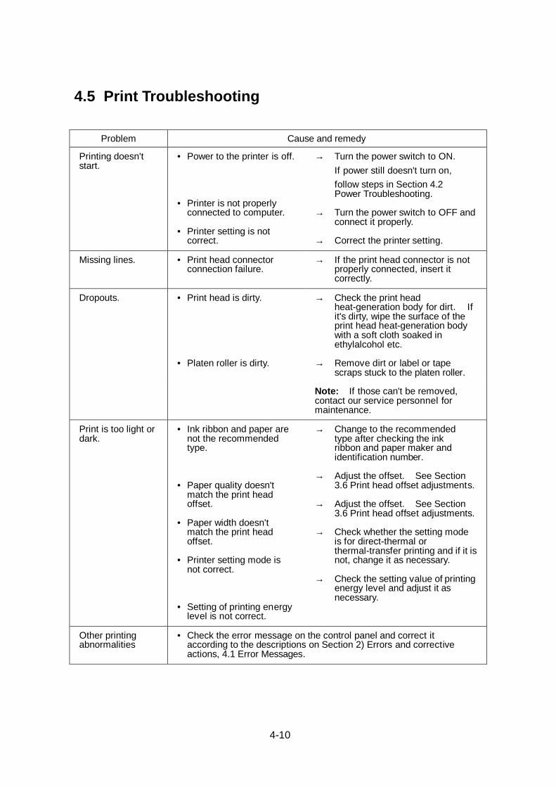
4.5 Print Troubleshooting
Problem Cause and remedy
Printing doesn'tstart.
• Power to the printer is off.
• Printer is not properlyconnected to computer.
• Printer setting is notcorrect.
→ Turn the power switch to ON.
If power still doesn't turn on,
follow steps in Section 4.2Power Troubleshooting.
→ Turn the power switch to OFF andconnect it properly.
→ Correct the printer setting.
Missing lines. • Print head connectorconnection failure.
→ If the print head connector is notproperly connected, insert itcorrectly.
Dropouts. • Print head is dirty.
• Platen roller is dirty.
→ Check the print headheat-generation body for dirt. Ifit's dirty, wipe the surface of theprint head heat-generation bodywith a soft cloth soaked inethylalcohol etc.
→ Remove dirt or label or tapescraps stuck to the platen roller.
Note: If those can't be removed,contact our service personnel formaintenance.
Print is too light ordark.
• Ink ribbon and paper arenot the recommendedtype.
• Paper quality doesn'tmatch the print headoffset.
• Paper width doesn'tmatch the print headoffset.
• Printer setting mode isnot correct.
• Setting of printing energylevel is not correct.
→ Change to the recommendedtype after checking the inkribbon and paper maker andidentification number.
→ Adjust the offset. See Section3.6 Print head offset adjustments.
→ Adjust the offset. See Section3.6 Print head offset adjustments.
→ Check whether the setting modeis for direct-thermal orthermal-transfer printing and if it isnot, change it as necessary.
→ Check the setting value of printingenergy level and adjust it asnecessary.
Other printingabnormalities
• Check the error message on the control panel and correct itaccording to the descriptions on Section 2) Errors and correctiveactions, 4.1 Error Messages.

4-11
4.6 Interface Troubleshooting
Problem Cause and remedy
Printer doesn'tprint.
The following are the probable causes:
Print disordered.
Error message isdisplayed andprinter doesn'tprint.
• Interface cable is notproperly connected.
• Interface cable is not thestandard type.
• Communicationparameter setting is notcorrect.
→ Check that the interface cableis connected properly.
→ Replace it.
→ Set the system maintenancemode from the control panel andcheck/correct the communicationparameter value.

4-12

5-1
Chapter 5Options
Factory or reseller (dealer) options:
5.1 Auto-Cutter Unit .................................................. 5-2
5.2 Peeler Unit .......................................................... 5-2
5.3 Adjustable Sensor (for CLP-6002 only) ............... 5-2
User options:
5.4 PCMCIA Memory Card........................................ 5-3

5-2
5.1 Auto-Cutter Unit
The auto-cutter unit that has been installed on the printer will be available.See the operation manual of the auto-cutter for details.
Specifications
• Cutting method: Circular cutter
• Max. thickness of cut paper: 0.01 in (0.254 mm)
• Min. length of cut paper: 1 in (25.4 mm)
5.2 Peeler Unit
The peeler unit that has been installed on the printer will be available.See the operation manual of the peeler unit for details.
Specifications
• Width of paper: 1−4.65 in (25.4−118 mm)
• Max. diameter for roll paper: 8 in (203 mm)
• Inner diameter for roll paper: 3 in (76 mm) or more
• Min. length of label: 1 in (25.4 mm)
• Thickness of paper: 0.0067 in (0.17 mm), max.
• Thickness of mount: 0.0027 in (0.07 mm), max.
• Unusable paper: Special paper (Whitepet, etc.) or tooflexible paper causing jams
5.3 Adjustable Sensor (for CLP-6002 only)
The adjustable sensor that has been installed on the printer will be available.See the operation manual of the adjustable sensor for details.
Specifications
• The basic specifications of the adjustable sensor are in accordance withthose of paper
• Adjustable sensor travel: 59 mm (2.3 in) from the left edge of the paper(reference line of setting paper). When the adjustable sensor is travelled tothe left edge, the black line sensor cannot detect the position of 2 mm (0.078 in)from the left edge of thepaper.

5-3
5.4 PCMCIA Memory Card
The PCMCIA memory card is used to:
1 Store print format files. Data in the field register area can be stored andloaded.
2 Store graphic data. For example, graphic data such as a corporate logo canbe stored and recalled from the PCMCIA memory card and printed.
3 Store downloaded HP Soft fonts.
Installation
1 Turn off the power to the printer.
2 Remove the PCMCIA memory card cover at the bottom of the printer (seefigure).
3 Insert the memory card.
4 Replace the PCMCIA memory card cover.
Notes: • Before use, carefully read and understand the instructions regardingthe PCMCIA memory card.
• Never try to insert or remove the PCMCIA memory card before thepower to the printer is turned off.
• Always close the PCMCIA memory card cover to keep out foreignmatter.
• If the PCMCIA memory card write failure occurs, check it with thetest command (STX.w).

5-4
6-1
Chapter 6Specifications
6.1 Main Specifications ............................................. 6-2
6.2 Interface.............................................................. 6-6
6.2.1 System configuration ............................... 6-6
6.2.2 Specification of interface.......................... 6-7
6.2.3 RS-232C loopback test............................ 6-8
6.2.4 RS-232C protocol .................................... 6-9
6.2.5 Interface pin assignment........................ 6-11
6.3 Outline of Command System ............................ 6-13
6.4 Example of Connection to a Computer.............. 6-14
6.5 Tear-Off Function .............................................. 6-15
6.5.1 Turning Tear ON/OFF ............................ 6-15
6.5.2 Tear-off when printing ............................ 6-15
6.5.3 Tear-off when feeding ............................ 6-16
6.5.4 Tear-off and type of data ........................ 6-17
6.5.5 Cut position adjustments........................ 6-17
6.5.6 When "fnnn" command isexecuted while tear-off is OFF ............... 6-18
6.5.7 Priority order .......................................... 6-19

6-2
6.1 Main Specifications
Item Description
Printing • Direct-thermal or thermal-transfer printing
• 203 dpi (8 dots/mm) print head(Main scanning line density: 8 dots/mm)(Subscanning line density: 8 lines/mm)
• Max. print width: 4.1 in (104 mm)
• Max. paper width: 4.65 in (118 mm)
• Max. print length: 32 in (812 mm)
Print speed • 2−7 inches/second in one-inch units (for CLP-6001)
• 2−6 inches/second in one-inch units (for CLP-6002)
Print mode • Batch mode: Performs normal printing (single or multi sheets)
• Peel mode: Prints and peels label from mount
• Cut mode: Prints and cuts by the specified number of sheets
• Tear-off mode: Cuts paper and feeds back to the print startingposition
Bar code generator One-dimensional bar code:
• Code 3 of 9 • POSTNET
• Interleaved 2 of 5 • UCC/EAN128 (for K-MART)
• UCC/EAN128 • Telepen
• UCC/EAN128 Random Weight • EAN-13 (JAN-13)
• Code 128 • HIBC (Modulus 43-used code 3 of 9)
• Codabar (NW-7) • Int 2 of 5 (Modulus 10-used Interleaved 2 of 5)
• EAN-8 (JAN-8) • UPC-E
• UPC-A • CASE CODE
• Plessey • UPC2DIG ADD
• Code 93 • FIM
• UPC5DIG ADD
Two-dimensional bar code:
• UPS Maxi Code • PDF-417

6-3
Item Description
Standard fonts • Font No. 0−6 (fixed pitch, alphanumeric)
• Font No. 7−8: OCR-A, OCR-B
• Font No. 9: CG Triumvirate smooth font; 6 pt, 8 pt, 10 pt, 12 pt, 14 pt,18 pt, 24 pt, 30 pt, 36 pt, and 48 pt
Character set is in accordance with code page 850
Media sensors • Transparent type sensor:Detects paper gap between labels, tag notch and paper end
• Reflective type sensor:Detects black line on back of paper and paper end
• Position of top edge of paper (paper home-position) adjustable withsoftware
• Ribbon end sensor:Detects ribbon absence or end (holder revolution)
• Label peeling sensor (optional)
Paper • Type of paper: Roll, label(continuous, die-cut, fanfold, tag or ticket)
• Kinds of paper: Direct-thermal paper, thermal-transfer paper
• Max. paper width: 4.65 in (118 mm)
• Min. paper width: 1 in (25.4 mm)
• Max. print length: 32 in (812 mm)
• Min. print length: 0.500 in (12.7 mm)
• Max. paper thickness: 0.01 in (0.254 mm)
• Min. paper thickness: 0.0025 in (0.063 mm)
• Roll paper diam.: max. outer diam.: 8 in (203 mm)paper core: 1.5−3 in (38−76 mm)
• Print density adjustable with software
Ribbon • Width: 1−4.5 in (25.4−114 mm) adjustable
• Length: 1181 feet (360 m), max.
• Max. outer diam.: 2.91 in (74 mm)
• Paper core inner diam.: 1 in (25.4 mm) ± 0.01 in (0.254 mm)

6-4
Item Description
Communicationinterface
• RS-232C (standard)
• Centronics (standard)
Indications, keys andswitches
• LEDs: Power and error
• LCD: Displays printer status, error contents,mode switch contents, etc
• Control panel keys: Pause, Feed and Stop
• Mode switch: For parameter setting for switchingbetween direct-thermal and thermal-transfer, communication, etc.
• Head up detection switch
• Power switch
Options By factory or reseller (dealer):
• Auto-cutter unit • Peeler unit
• Adjustable sensor (for CLP-6002 only)
By user:
• Flash memory card
Appearance andweight
• Height: 10.2 in (260 mm)
• Width: 10.2 in (260 mm)
• Depth: 16.9 in (430 mm)
• Weight: 24.2 lbs (11.0 kg)
Power • Input voltage 120V: −10%+6%, 2.5A, 60Hz (U.S.A., Canada)
• Input voltage 220−240V: −10%+6%, 1.2A, 50/60Hz (Europe)
Standards 120V: UL1950 CSA: No. 950 FCC: Class A
220−240V: EN60950, EN55022 Class A, EN50082-1, IEC801-2,IEC801-3, IEC801-4

6-5
Item Description
Environment • Operating conditions:Temperature: 5−35°C (41−95°F)Humidity: 30−80% (noncondensing)
• Storage:Temperature: -20−60°C (-4−140°F)Humidity: 5−85%
• Ventilation:Convective circulation. Air vent must be away from wall etc(to prevent fire)
• Dust:Free from conductive or corrosive matter

6-6
6.2 Interface
6.2.1 System configuration
The printer is connected to a computer and prints labels according to the commandfrom the computer.
Two methods of interface with a computer are as follows:
(1) Serial interface: RS-232C (standard)
Computer
RS-232C interface
RS-232C interface
Printer
(2) Parallel interface: Centronics (standard)
Computer
Centronics interface
Centronics interface
Printer

6-7
6.2.2 Specification of interface
(1) Serial interface
Method Asynchronous serial interfaceRS-232C
Connector DSUB 25-pin
Protocol control XON/XOFF and CTS/DTR
Receive buffer 32K bytes
Receiving data stops when the remaining buffer reaches 2Kbytes and resumes when the remaining buffer reaches 4K bytes
Baud rate 300, 600, 1200, 2400, 4800, 9600, 19200, 38400 bps
Bit length 7- or 8-bit
Stop bit Fixed
When printer receives data, stop bit is fixed at 1, and whenprinter transmits data, stop bit is fixed at 2. But computer cantransmit and receive data, regardless of stop bit at 1 or 2
Parity No
(2) Parallel interface
Method 8-bit parallel
Connector 36-pin unphenol type
Synchronoussystem
Strobe pulse
Handshaking ACKNLG and BUSY signals
Signal level TTL

6-8
6.2.3 RS-232C loopback test
After connector wiring as shown in the figure, the test mode is turned on.The printer will receive data that has been transmitted by printer itself and thetest of receiving and transmitting data will be performed.
RS-232C test
Fig. Loopback test

6-9
6.2.4 RS-232C protocol
(1) X-ON/X-OFF system (see the figure)
This is a control system in which the data transmission requestsignal (X-ON (11H) code) and the data transmission stop requestsignal (X-OFF (13H) code) are output.
Requirements of output of X-ON code:
• When the power is switched to ON.
• When the remaining buffer is 2K bytes or less, the X-OFF isoutput, and the remaining buffer is 4K bytes or more.
Requirements of output of X-OFF code:
• When printer error occurs.
• When the remaining buffer is 2K bytes or less.
Note: Even if each code is ready for output, the same code cannot betransmitted twice successively (except when the power is turned onor the printer is reset from the control panel).
Fig. Buffer in use
Receive buffer = 32K bytes
2K bytes
4K bytes
X-OFF code outputX-ON code output
Receiving data

6-10
(2) Ready/Busy system (see the figure)
This is a control system in which the DTR signal is output at Ready(High)/Busy(Low) level.
Requirements of DTR "High":
• When the printer is "on line."
• When the remaining buffer is less than 2K bytes.
However, when the remaining buffer of less than 2K bytes isdetected, the printer keeps a "Low" level until the remainingbuffer is 4K bytes or more.
• When printer alarms such as the printer switched to "off line"occur.
6-11
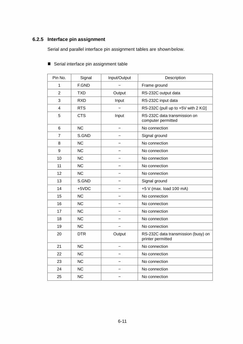
6.2.5 Interface pin assignment
Serial and parallel interface pin assignment tables are shownbelow.
Serial interface pin assignment table
Pin No. Signal Input/Output Description
1 F.GND − Frame ground
2 TXD Output RS-232C output data
3 RXD Input RS-232C input data
4 RTS − RS-232C (pull up to +5V with 2 KΩ]
5 CTS Input RS-232C data transmission oncomputer permitted
6 NC − No connection
7 S.GND − Signal ground
8 NC − No connection
9 NC − No connection
10 NC − No connection
11 NC − No connection
12 NC − No connection
13 S.GND − Signal ground
14 +5VDC − +5 V (max. load 100 mA)
15 NC − No connection
16 NC − No connection
17 NC − No connection
18 NC − No connection
19 NC − No connection
20 DTR Output RS-232C data transmission (busy) onprinter permitted
21 NC − No connection
22 NC − No connection
23 NC − No connection
24 NC − No connection
25 NC − No connection

6-12
Parallel interface pin assignment table
Pin No. Signal Input/Output Description
1 STROBE Input Strobe signal for reading 8-bit data
2−9 DATA1-8 Input 8-bit parallel signal
10 ACKNLG Output 8-bit data request signal
11 BUSY Output Signal specifying printer busy
12 PERROR Output Signal specifying paper absence
13 SELECT Output Signal specifying printer "on line"(printing) or "off line" (pause)
14 AUTOFD Input Invalidness (ignorance)
15 NC − No use
16 S.GND − Signal ground
17 FGND − Frame ground
18 P.L.H Output Signal specifying peripheral logic high(pull up to +5V with 2 KΩ]
19−30 GND − Ground for twisted pair return
31 INIT Input Printer reset
32 FAULT Output Signal specifying printer error
33−35 NC − No use
36 SELECTIN Input Invalidness (ignorance)

6-13
6.3 Outline of Command System
For details about command system, see the Command Reference separatelyavailable.
Commands for this printer consist of a string of ASCII code and end with "CR"(decimal: 13, hex: 0D). Generally, commands are classified into two types,system-level commands and label format commands.
System-level commands are used for system-level operations such as printerstatus output, sensor selection and memory card maintenance. On theother hand, label format commands are used for definition of printing contentssuch as character data, bar code data, print speed, and print density.
System-level commands start with ASCII "SOH" ($01) or "STX" ($02).
Commands which start with "SOH" are required for realtime execution.When received, they are executed immediately even during printing.Commands which start with "STX" enter the buffer area once and then areexecuted in the order of data reception.
Label format commands end with "CR", following the system-levelcommands' "STX" + "L."
Commands that start with "SOH":
Executed immediately after receiving data
(e.g. stop of printing, output of printer status, etc.)
System-level commands
start with ASCII "SOH" ($01) or"STX" ($02).
Commands that start with "STX":
Executed in the order of data input to the receivebuffer
(e.g. switching of sensor, memory card maintenance,etc.)
"STX" + "L" ↓ ↑ "E" (with print)
"X" (without print)
Print parameter control
Character data definition commands
Bar code definition commands
Graphic commands
Label format commands
end with "CR"
Other commands

6-14
6.4 Example of Connection to a Computer
When RS-232C is used:
IBM PC compatible
Communication control: XON/XOFF or CTS/DTR

6-15
6.5 Tear-Off Function
The tear-off function eliminates the waste of labels when tearing manually.It allows the paper to automatically advance to the tear position after printing.
When this function is turned on, the printer checks for print request for 0.5second after printing and if no print request is made, the printer feeds paper tothe manual tear position. The printer will feed back paper to the print startposition when the next print job is sent.
If data is transmitted continuously from the computer, the tear-off function willbe suppressed to increase throughput.
6.5.1 Turning Tear ON/OFF
Tear can be turned to ON or OFF from the control panel. Default is OFF.
Indications on the control panel are as follows:
LCD
Tear-off invalid Tear-off valid
"Tear OFF" "Tear ON"
6.5.2 Tear-off when printing
The tear-off will start if no print data is transmitted for 0.5 second after printing.If the next data is transmitted before starting tear-off, the printer will start nextprinting without tear-off.
Also, the tear-off is only performed for the final label of each batch processing.
(The tear-off is not performed until the specified number of print sheets iscompleted.)

6-16
• Paper is fed to the tear position
• When manual tearing is needed, tear the label at this time.
• Performs next label printing.
When next print data is transmitted from the computer, the printer feeds backpaper to the previous print completed position and resumes printing.
6.5.3 Tear-off when feeding
• If no print data is transmitted for 0.5 second after feeding, the tear-off willstart. If the Feed key is pressed again before starting tear-off, the printerwill feed paper without tear-off.
• Paper is fed to the tear position.
• When manual tearing is needed, tear the label at this time.
• Performs next feeding or label printing.
If the Feed key is pressed or next print data is transmitted from the computer,the printer feeds back the paper to the previous print completed position andresumes feeding or printing.
Tear-off will start if no data is sentfor 0.5 second after printing
Paper is fed to the position wheremanual tearing is possible
Paper is fed back to the previousprint completed position and printingresumes
Peeling (manual tearing)
Platen
Paper position sensor
Print head

6-17
6.5.4 Tear-off and type of data
When the tear-off is valid, the printer monitors the print data for 0.5 secondduring or after printing. If print data is transm itted within 0.5 second during orafter printing, the printer will start next printing without tear-off. (When data isreceived during printing, the time of monitoring 0.5 second is not inserted.)
The commands for this printer are mainly classified into the immediatelyexecution commands starting with "SOH" and the sequentially executioncommands starting with "STX." In the tear-off function, only thesequentially execution commands related to print processing contents aremonitored but the immediately execution commands are not monitored.
Therefore, even if the printer status or the remaining number of print sheetsis read out by using the immediately execution commands during printing,the tear-off will be performed after printing. On the other hand, if thesequentially execution commands are used during printing or within 0.5second after printing to transmit print-related data, the printer will start nextprinting without tear-off. (For details, see the Command Reference.)
6.5.5 Cut position adjustments
• The cut position can be set with the "fnnn" of the system-levelcommands. When the tear-off function is turned on, the followinginitialization value is set in the printer.
Initialization value: fnnn = f733 (73.3 mm)
The values higher or lower will increase or decrease the amount of feedin the tear-off.
Onnnn: Paper position setting
fnnn: Feed position setting
fnnn <= OnnnnFeed or back-feed is notperformed
fnnn > OnnnnFeed or back-feed isperformed
OnnnnTear bar
Paper position sensor
Print head
Tear offfnnn

6-18
• Initialization parameter values
Initialization values for print or tear position are described below by eachoperating mode.
In Native ON Unit: mm (inch)
Normalprint Auto-cutter Peeling Tear-off Minimum
value
Print position(Onnnn, form offset) 55.9(2.2) 12.7(0.5)
Tear position(fnnn, feed offset) 55.9(2.2) 86.3(3.40) 68.5(2.7) 73.5(2.9) 12.7(0.5)
If values lower than the minimum value are set, the initialization value will beset.
In Native OFF Unit: mm (inch)
Normalprint Auto-ı cutter Peeling Tear-off Minimum
value
Print position(Onnnn, form offset) 27.9(1.1) 12.7(0.5)
Tear position(fnnn, feed offset) 27.9(1.1) 58.3(2.3) 37.0(1.46) 42.1(1.66) 12.7(0.5)
If values lower than the minimum value are set, the initialization value will be set.
6.5.6 When "fnnn" command is executed while tear-off is OFF
Even with the tear-off OFF, the paper will be fed to the "fnnn"-specified positionafter printing if an "fnnn > Onnnn" value is set by using the "fnnn" command.
This function can be used in such cases as another device is incorporated in theprinter.
When operating with the FARGO, the following is different from those in thetear-off ON:
• The paper is fed immediately after printing, whereas, in the tear-off ON thepaper is fed when no data is transmitted for 0.5 second after printing.
However, if the next print data is transmitted during printing, the printer willstart printing without feed or back-feed.

6-19
6.5.7 Priority order
The following three functions (optional) cannot be performed simultaneously.
If commands for those three functions are received simultaneously, they will beexecuted in the following order of priority:
1st: Auto-cutting
2nd: Peeling
3rd: Tear-off

6-20

Citizen America Corporation831 S. Douglas Street, Suite 121El Segundo, CA 90245(310) 643-9825U.S.A.
Citizen Systems Europe Ltd.Mettinger Strasse 1173728 EsslingenGermany
337 Bath Road, SloughBerkshire, SL1 5PRUnited Kingdom
JE99317-10(70903743) Printed in Japan