cmm error simulator users guide - select calibration error... · 2018-04-25 · using the newer...
TRANSCRIPT
CMM Error Simulator Users Guide
Copyright © 2018 by Select Calibration Inc. All rights reserved.

CMM Error Simulator Users Guide
Table of ContentsIntroduction..............................................................................................3Overview..................................................................................................3Visualizer Tab............................................................................................4
Graphical View........................................................................................4Graphical View 3D Controls......................................................................4OpenGL.................................................................................................5Measurement Results..............................................................................6Measurement Results – Save Text.............................................................7Measurement Results – Export Measurements.............................................7Measurement Results – Evaluation Report..................................................7Machine Errors.......................................................................................7
Machine Tab..............................................................................................9Machine Management............................................................................10Kinematic Order....................................................................................10Axis Dimensions and Map Origin..............................................................11Machine Error Parameters.......................................................................12Expression Variables..............................................................................13Deflection Expressions...........................................................................14Expression Signs...................................................................................14Straightness Signs.................................................................................14
Measurements Tab...................................................................................14Measurement Management.....................................................................15Expression Variables..............................................................................15Measurement Variable Example...............................................................16Probe Offset Sign..................................................................................18Laser Measurements..............................................................................18
Revision History.......................................................................................19
Select Calibration Inc. April 25, 2018 Page 2 of 19
CMM Error Simulator Users Guide
IntroductionThe CMM Error Simulator utility was written to provide unbiased CMM measurement results inorder to assist in the development of tools and procedures necessary for efficient calibration ofcoordinate measuring machines. Developing methods to extract specific machine errors frommeasurements require accurate test data so that methods can be evaluated properly. Using areal CMM can be problematic as measurement noise can bias the results. Using a real CMM forthis task by introducing errors into a CMM compensation map adds error into the testing process.Coordinate measuring machines must have physical errors to be evaluated properly.
In addition to providing test data for tool development the CMM Error Simulator was also designedto perform automatic comparison testing for different measurement strategies. This can be usedto compare performance test standards or to simply evaluate a chosen measurement pattern.Manually testing all combinations of machine errors can be a very long process so automating thismakes sense.
The CMM Error Simulator utility can duplicate a variety of machine error conditions from variousvendors and axis configurations. This includes vertical and horizontal arm coordinate measuringmachines in one of the four common kinematic chain orders. For kinematic axis orders that aretypically associated with horizontal arm CMM's it is possible to introduce errors due to towerdeflection.
The measurements tests can use variables allowing for dynamic adjustments between differentconfigurations of machines without having to change any of the data. If setup as intended nochanges to any measurement should be required to run any measurement test even if themachine configuration changes significantly.
This utility is cross platform and can be compiled to run on GNU/Linux, OSX, and Windows.
OverviewThe CMM Error Simulator uses a single dialog window to the main interface. There are no menuor other non-visual controls. The machine and measurements are automatically stored in the.errorsimulator sub folder of the users home folder regardless of the operating system theprogram is run on. The naming convention of a dot followed by the name of the application istypical for unix based applications.
Select Calibration Inc. April 25, 2018 Page 3 of 19
CMM Error Simulator Users Guide
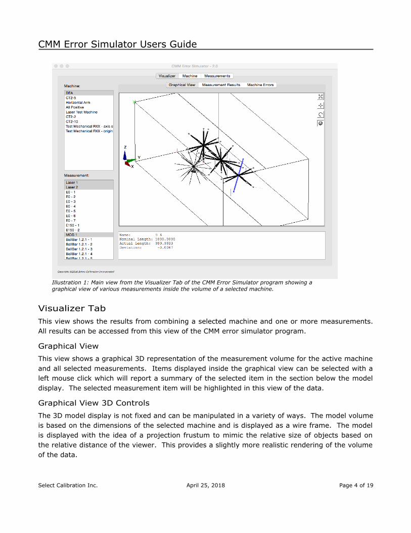
Illustration 1: Main view from the Visualizer Tab of the CMM Error Simulator program showing a graphical view of various measurements inside the volume of a selected machine.
Visualizer TabThis view shows the results from combining a selected machine and one or more measurements.All results can be accessed from this view of the CMM error simulator program.
Graphical View
This view shows a graphical 3D representation of the measurement volume for the active machineand all selected measurements. Items displayed inside the graphical view can be selected with aleft mouse click which will report a summary of the selected item in the section below the modeldisplay. The selected measurement item will be highlighted in this view of the data.
Graphical View 3D Controls
The 3D model display is not fixed and can be manipulated in a variety of ways. The model volumeis based on the dimensions of the selected machine and is displayed as a wire frame. The modelis displayed with the idea of a projection frustum to mimic the relative size of objects based onthe relative distance of the viewer. This provides a slightly more realistic rendering of the volumeof the data.
Select Calibration Inc. April 25, 2018 Page 4 of 19
CMM Error Simulator Users Guide
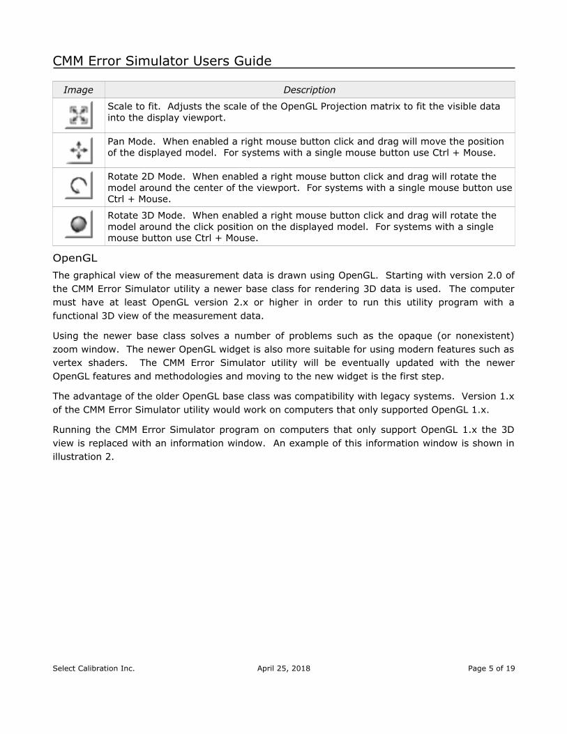
Image Description
Scale to fit. Adjusts the scale of the OpenGL Projection matrix to fit the visible data into the display viewport.
Pan Mode. When enabled a right mouse button click and drag will move the position of the displayed model. For systems with a single mouse button use Ctrl + Mouse.
Rotate 2D Mode. When enabled a right mouse button click and drag will rotate the model around the center of the viewport. For systems with a single mouse button useCtrl + Mouse.
Rotate 3D Mode. When enabled a right mouse button click and drag will rotate the model around the click position on the displayed model. For systems with a single mouse button use Ctrl + Mouse.
OpenGL
The graphical view of the measurement data is drawn using OpenGL. Starting with version 2.0 ofthe CMM Error Simulator utility a newer base class for rendering 3D data is used. The computermust have at least OpenGL version 2.x or higher in order to run this utility program with afunctional 3D view of the measurement data.
Using the newer base class solves a number of problems such as the opaque (or nonexistent)zoom window. The newer OpenGL widget is also more suitable for using modern features such asvertex shaders. The CMM Error Simulator utility will be eventually updated with the newerOpenGL features and methodologies and moving to the new widget is the first step.
The advantage of the older OpenGL base class was compatibility with legacy systems. Version 1.xof the CMM Error Simulator utility would work on computers that only supported OpenGL 1.x.
Running the CMM Error Simulator program on computers that only support OpenGL 1.x the 3Dview is replaced with an information window. An example of this information window is shown inillustration 2.
Select Calibration Inc. April 25, 2018 Page 5 of 19

CMM Error Simulator Users Guide
Illustration 2: Information screen that is displayed with unsupported OpenGL versions.
Measurement Results
This view of the Visualizer Tab shows the text result of all selected measurements. Depending onthe type of data some measurements are combined into a single table such as the ball bar data.Measurements that consist of more than one measured value are reported as a group for eachselected measurement.
The following is a partial example of the measurement of a Renishaw Machine Checking Gauge asdisplayed in this view:
MCG Measurement----------------------------------------------------------------------------------------Name: MCG 1Probe Offset: 0.0000, 0.0000, -50.0000Center Position: 500.0000, 1000.0000, -500.0000
Elevation Azimuth Length Error---------------------------------------------------------------------------------------- -45.0006 0.0010 499.9979 -0.0021 -45.0002 45.0015 500.0013 0.0013 -44.9998 90.0010 500.0019 0.0019 -44.9997 135.0007 500.0001 0.0001 -44.9997 180.0008 500.0004 0.0004 -44.9995 225.0004 500.0021 0.0021 -44.9998 269.9997 500.0011 0.0011 -45.0004 314.9998 499.9978 -0.0022 -0.0004 0.0008 499.9988 -0.0012... 45.0005 180.0008 499.9979 -0.0021
Select Calibration Inc. April 25, 2018 Page 6 of 19
CMM Error Simulator Users Guide
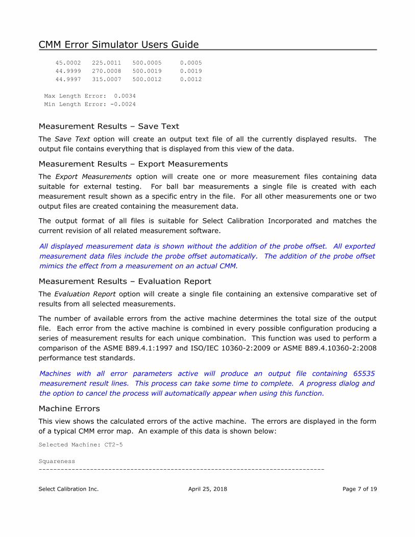
45.0002 225.0011 500.0005 0.0005 44.9999 270.0008 500.0019 0.0019 44.9997 315.0007 500.0012 0.0012
Max Length Error: 0.0034Min Length Error: -0.0024
Measurement Results – Save Text
The Save Text option will create an output text file of all the currently displayed results. Theoutput file contains everything that is displayed from this view of the data.
Measurement Results – Export Measurements
The Export Measurements option will create one or more measurement files containing datasuitable for external testing. For ball bar measurements a single file is created with eachmeasurement result shown as a specific entry in the file. For all other measurements one or twooutput files are created containing the measurement data.
The output format of all files is suitable for Select Calibration Incorporated and matches thecurrent revision of all related measurement software.
All displayed measurement data is shown without the addition of the probe offset. All exportedmeasurement data files include the probe offset automatically. The addition of the probe offsetmimics the effect from a measurement on an actual CMM.
Measurement Results – Evaluation Report
The Evaluation Report option will create a single file containing an extensive comparative set ofresults from all selected measurements.
The number of available errors from the active machine determines the total size of the outputfile. Each error from the active machine is combined in every possible configuration producing aseries of measurement results for each unique combination. This function was used to perform acomparison of the ASME B89.4.1:1997 and ISO/IEC 10360-2:2009 or ASME B89.4.10360-2:2008performance test standards.
Machines with all error parameters active will produce an output file containing 65535measurement result lines. This process can take some time to complete. A progress dialog andthe option to cancel the process will automatically appear when using this function.
Machine Errors
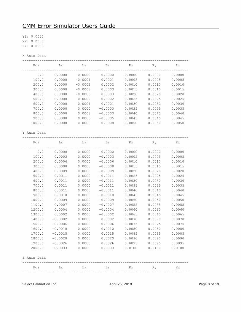
This view shows the calculated errors of the active machine. The errors are displayed in the formof a typical CMM error map. An example of this data is shown below:
Selected Machine: CT2-5
Squareness------------------------------------------------------------------------------
Select Calibration Inc. April 25, 2018 Page 7 of 19
CMM Error Simulator Users Guide
YZ: 0.0050XY: 0.0050ZX: 0.0050
X Axis Data------------------------------------------------------------------------------ Pos Lx Ly Lz Rx Ry Rz------------------------------------------------------------------------------ 0.0 0.0000 0.0000 0.0000 0.0000 0.0000 0.0000 100.0 0.0000 -0.0001 0.0001 0.0005 0.0005 0.0005 200.0 0.0000 -0.0002 0.0002 0.0010 0.0010 0.0010 300.0 0.0000 -0.0003 0.0003 0.0015 0.0015 0.0015 400.0 0.0000 -0.0003 0.0003 0.0020 0.0020 0.0020 500.0 0.0000 -0.0002 0.0002 0.0025 0.0025 0.0025 600.0 0.0000 -0.0001 0.0001 0.0030 0.0030 0.0030 700.0 0.0000 0.0000 -0.0000 0.0035 0.0035 0.0035 800.0 0.0000 0.0003 -0.0003 0.0040 0.0040 0.0040 900.0 0.0000 0.0005 -0.0005 0.0045 0.0045 0.0045 1000.0 0.0000 0.0008 -0.0008 0.0050 0.0050 0.0050
Y Axis Data------------------------------------------------------------------------------ Pos Lx Ly Lz Rx Ry Rz------------------------------------------------------------------------------ 0.0 0.0000 0.0000 0.0000 0.0000 0.0000 0.0000 100.0 0.0003 0.0000 -0.0003 0.0005 0.0005 0.0005 200.0 0.0006 0.0000 -0.0006 0.0010 0.0010 0.0010 300.0 0.0008 0.0000 -0.0008 0.0015 0.0015 0.0015 400.0 0.0009 0.0000 -0.0009 0.0020 0.0020 0.0020 500.0 0.0011 0.0000 -0.0011 0.0025 0.0025 0.0025 600.0 0.0011 0.0000 -0.0011 0.0030 0.0030 0.0030 700.0 0.0011 0.0000 -0.0011 0.0035 0.0035 0.0035 800.0 0.0011 0.0000 -0.0011 0.0040 0.0040 0.0040 900.0 0.0010 0.0000 -0.0010 0.0045 0.0045 0.0045 1000.0 0.0009 0.0000 -0.0009 0.0050 0.0050 0.0050 1100.0 0.0007 0.0000 -0.0007 0.0055 0.0055 0.0055 1200.0 0.0004 0.0000 -0.0004 0.0060 0.0060 0.0060 1300.0 0.0002 0.0000 -0.0002 0.0065 0.0065 0.0065 1400.0 -0.0002 0.0000 0.0002 0.0070 0.0070 0.0070 1500.0 -0.0006 0.0000 0.0006 0.0075 0.0075 0.0075 1600.0 -0.0010 0.0000 0.0010 0.0080 0.0080 0.0080 1700.0 -0.0015 0.0000 0.0015 0.0085 0.0085 0.0085 1800.0 -0.0020 0.0000 0.0020 0.0090 0.0090 0.0090 1900.0 -0.0026 0.0000 0.0026 0.0095 0.0095 0.0095 2000.0 -0.0033 0.0000 0.0033 0.0100 0.0100 0.0100
Z Axis Data------------------------------------------------------------------------------ Pos Lx Ly Lz Rx Ry Rz------------------------------------------------------------------------------
Select Calibration Inc. April 25, 2018 Page 8 of 19

CMM Error Simulator Users Guide
-1000.0 0.0008 -0.0008 0.0000 -0.0050 -0.0050 -0.0050 -900.0 0.0005 -0.0005 0.0000 -0.0045 -0.0045 -0.0045 -800.0 0.0003 -0.0003 0.0000 -0.0040 -0.0040 -0.0040 -700.0 0.0000 -0.0000 0.0000 -0.0035 -0.0035 -0.0035 -600.0 -0.0001 0.0001 0.0000 -0.0030 -0.0030 -0.0030 -500.0 -0.0002 0.0002 0.0000 -0.0025 -0.0025 -0.0025 -400.0 -0.0003 0.0003 0.0000 -0.0020 -0.0020 -0.0020 -300.0 -0.0003 0.0003 0.0000 -0.0015 -0.0015 -0.0015 -200.0 -0.0002 0.0002 0.0000 -0.0010 -0.0010 -0.0010 -100.0 -0.0001 0.0001 0.0000 -0.0005 -0.0005 -0.0005 0.0 0.0000 0.0000 0.0000 0.0000 0.0000 0.0000
This data is generated based on the increment values shown at the top of the Machine Errordisplay of the data. The data can be viewed with any desired increment by editing the fields andpressing the Update button.
This data is provided to show the end result of all machine errors. This data is not used forcalculation of the measurement errors therefore the input map increments have no affect on anycalculated measurement result.
Machine TabThis view is for managing all available simulated coordinate measuring machines.
Select Calibration Inc. April 25, 2018 Page 9 of 19
CMM Error Simulator Users Guide
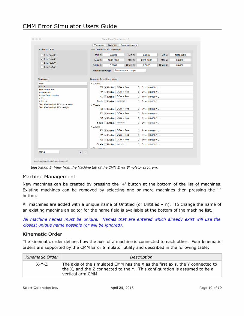
Illustration 3: View from the Machine tab of the CMM Error Simulator program.
Machine Management
New machines can be created by pressing the '+' button at the bottom of the list of machines.Existing machines can be removed by selecting one or more machines then pressing the '-'button.
All machines are added with a unique name of Untitled (or Untitled – n). To change the name ofan existing machine an editor for the name field is available at the bottom of the machine list.
All machine names must be unique. Names that are entered which already exist will use theclosest unique name possible (or will be ignored).
Kinematic Order
The kinematic order defines how the axis of a machine is connected to each other. Four kinematicorders are supported by the CMM Error Simulator utility and described in the following table:
Kinematic Order Description
X-Y-Z The axis of the simulated CMM has the X as the first axis, the Y connected to the X, and the Z connected to the Y. This configuration is assumed to be a vertical arm CMM.
Select Calibration Inc. April 25, 2018 Page 10 of 19

CMM Error Simulator Users Guide
Kinematic Order Description
Y-X-Z The axis of the simulated CMM has the Y as the first axis, the X connected to the Y, and the Z connected to the X. This configuration is assumed to be a vertical arm CMM.
X-Z-Y The axis of the simulated CMM has the X as the first axis, the Z connected to the X, and the Y connected to the Z. This configuration is assumed to be a horizontal arm CMM.
Y-Z-X The axis of the simulated CMM has the Y as the first axis, the Z connected to the Y, and the X connected to the Z. This configuration is assumed to be a horizontal arm CMM.
Axis Dimensions and Map Origin
This section defines the limits of the CMM machine axis. The origin entries define themathematical rotation zero point for this machine.
The machine origin option allows for placing the mechanical rotation point at positions other thanthe mathematical rotation point. The default is to use the same position as the mathematicalrotation point but this can be to different positions in the machine volume if required.
Illustration 4 shows an example for the mechanical rotation point. In most cases this option canbe ignored but when specifically testing for the effect from having the compensation applied fromone end of an axis and compensating from the other this feature is invaluable.
The list of possible axis combinations is suitable for generic testing. Not every possible axiscombination is available or even technically required.
Illustration 4: Example of the effect of rotation error RXX at different points in the X axis affectingthe Y axis straightness.
Select Calibration Inc. April 25, 2018 Page 11 of 19

CMM Error Simulator Users Guide
The options are listed based on the sign of the axis. The mechanical rotation is always assumedto be at either end of a machine axis. For example, the option 'Axis positions -X +Y +Z' will placethe mechanical origin at the negative end of the X axis and the positive ends of the Y and Z axis.
Machine Error Parameters
The X, Y, and Z machine axis can have up to four error parameters. For horizontal arm CMM's anadditional D axis is added and allows a single entry for an expression suitable to describe thetower deflection.
All parameters are entered as a constant or formula expression. The following are examples ofdifferent expressions that can be used to describe machine axis errors:
Er=0.005
Er=0.005∗L
Er=0.005+0.002∗L+0.003∗L2−0.004∗L3
The first example is a constant. This value will be applied evenly to all data of the simulatedCMM. The second example is a gradient with the variable 'L' substituted for the actual position inthe machine volume. The third example is in the form of a polynomial with coefficients. Theresulting shape from this expression is complex.
Using a constant for angular data is equivalent to adding a squareness error. The affected axisand rotation direction can be precisely controlled using constants.
Select Calibration Inc. April 25, 2018 Page 12 of 19

CMM Error Simulator Users Guide
Illustration 5: Interpretation of machine error for rotation aroundZ axis (viewer).
The interpretation of the machine error is a description of what the physical machinecharacteristics are. A machine error with a counter clockwise positive sign and a positive errorexpression will create a simulated machine as shown in illustration 5. The input error expressionsrepresent the physical machine errors and the measurement results are what would be expectedon a machine with these physical errors and a zero error map.
Expression Variables.
The following are variables that can be used for the machine error expressions:
Variable Description
L Position in the map coordinates specific for each axis. The value is from the XYZ zero point regardless if this position is inside the machine volume or not.
PUp Position from the XYZ zero point specifically for the vertical axis (Z). This variable is only used for the deflection axis parameter.
POut Position from the XYZ zero point specifically for the horizontal axis (Y or X). This variable is only used for the deflection axis parameter.
LUp Length from the minimum position of the vertical axis (Z). This variable is only used for the deflection axis parameter.
LOut Length from the minimum position of the horizontal axis (Y or X). This variable is only used for the deflection axis parameter.
Select Calibration Inc. April 25, 2018 Page 13 of 19

CMM Error Simulator Users Guide
Deflection Expressions
The tower deflection of a horizontal arm are not a constant expression. The value that is used forall evaluations is based on the result of the expression and is usually unique depending on thevertical and horizontal position. Most horizontal arm CMM's can be described with the followingexpression:
Rt=E∗LUp∗LOut
When viewing the machine error data in the Visualizer Tab the tower deflection data is presentedin a table showing the product of the expression at different points in the axis related to the data.
Expression Signs
For angular data the interpretation of the machine error expression is determined by the selectionof CCW=Pos or CW=Pos. This selection does not change the sign of the expression but simplyhow the data is to be interpreted.
For scale data a normal sign is based on the principal of comparing to a laser. If the machinescale error correction is more positive when the laser reading is more positive then the reportedmachine position then the sign is considered Normal. Inverted is the opposite where a morepositive laser reading would be entered as a negative correction.
Squareness interpretation is based on true angle measurements between the primary andsecondary axis for each of the three parameters. The sign settings show options based on howmeasurements would be interpreted at 45 degree angles between the two affected machine axis.
Straightness Signs
The straightness parameters are calculated automatically from the input angular data. Theseparameters cannot be directly accessed.
Measurements TabThis view allows the editing of one or more measurements that are to be evaluated on thedifferent simulated machines. Four different kinds of measurements are currently supported bythe CMM Error Simulator program:
• Laser (six parameter).
• ISO/IEC 10360-2
• Renishaw Machine Checking Gauge
• ASME B89.4.1 ball bar
Select Calibration Inc. April 25, 2018 Page 14 of 19

CMM Error Simulator Users Guide
Illustration 6: View of the measurements tab with the MCG gauge active.
Measurement Management
New measurements can be created by pressing the '+' button at the bottom of the list ofmeasurements. Existing measurements can be removed by selecting one or more measurementsthen pressing the '-' button.
The name of the new measurement will be automatically generated from a default name or will bebased on the name of the currently selected measurement item if a selected item exists. Thename can be altered by editing the Name field at the top of the measurement parameters.
When a measurement is selected the editor will automatically highlight the settings specific for thetype of selected measurement with all other measurement types disabled. To have allmeasurement types active unselect any active measurement first.
The type of measurement that is added is based on what is currently active. For example, to adda new ball bar measurement ensure the ball bar editor is the active view.
Expression Variables.
The following are variables that can be used for measurement expressions:
Select Calibration Inc. April 25, 2018 Page 15 of 19

CMM Error Simulator Users Guide
Variable Description
XMin The minimum X axis machine coordinate.
YMin The minimum Y axis machine coordinate.
ZMin The minimum Z axis machine coordinate.
XMax The maximum X axis machine coordinate.
YMax The maximum Y axis machine coordinate.
ZMax The maximum Z axis machine coordinate.
XMid The center position of the X axis.
YMid The center position of the Y axis.
ZMid The center position of the Z axis.
AxisMin The shortest length of the X, Y, or Z axis.
AxisMax The longest length of the X, Y, or Z axis.
L The nominal measurement length.
R The nominal measurement length divided by two (L/2).
I The normalized I value of the IJK direction.
J The normalized J value of the IJK direction.
K The normalized K value of the IJK direction.
Some variables cannot be used in fields that result in the creation of the variable (recursivevariable). For example, the variable 'L' cannot be used inside any length field as the value of thisvariable must be determined by solving the expression of this field first.
Measurement Variable Example
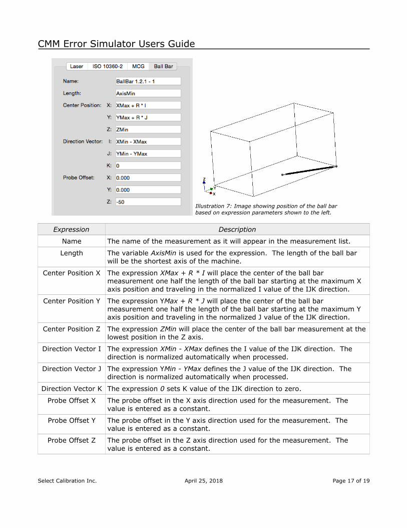
The following shows an example of a measurement expression for a ball bar. The table followingthe image describes the different variables used.
In this example the goal was to have a ball bar placed at the bottom of the machines Z axis in adirection between the back/left and front/right corners. Since the dimensions of the machine arenot (or may not) be cubical the I and J values would not be 0.707 and 0.707. Also, the position ofone of the two spheres must be located at the back/left corner of the machines measurementvolume. The length of the ball bar must be set to be the same as the shortest machine axis.
Select Calibration Inc. April 25, 2018 Page 16 of 19
CMM Error Simulator Users Guide
Illustration 7: Image showing position of the ball bar based on expression parameters shown to the left.
Expression Description
Name The name of the measurement as it will appear in the measurement list.
Length The variable AxisMin is used for the expression. The length of the ball bar will be the shortest axis of the machine.
Center Position X The expression XMax + R * I will place the center of the ball bar measurement one half the length of the ball bar starting at the maximum X axis position and traveling in the normalized I value of the IJK direction.
Center Position Y The expression YMax + R * J will place the center of the ball bar measurement one half the length of the ball bar starting at the maximum Y axis position and traveling in the normalized J value of the IJK direction.
Center Position Z The expression ZMin will place the center of the ball bar measurement at thelowest position in the Z axis.
Direction Vector I The expression XMin - XMax defines the I value of the IJK direction. The direction is normalized automatically when processed.
Direction Vector J The expression YMin - YMax defines the J value of the IJK direction. The direction is normalized automatically when processed.
Direction Vector K The expression 0 sets K value of the IJK direction to zero.
Probe Offset X The probe offset in the X axis direction used for the measurement. The value is entered as a constant.
Probe Offset Y The probe offset in the Y axis direction used for the measurement. The value is entered as a constant.
Probe Offset Z The probe offset in the Z axis direction used for the measurement. The value is entered as a constant.
Select Calibration Inc. April 25, 2018 Page 17 of 19

CMM Error Simulator Users Guide
Probe Offset Sign
The sign for the probe offset is always interpreted as the relative position of the stylus ruby fromthe probe connection point at the end of the last axis of the machine. The signs for all axis isusing the standard convention and is reversed as compared to some inspection software (PC-DMIS for example).
All measurements will draw the relative position of the stylus provided the probe offset is notzero.
Laser Measurements
All simulated measurement results when using the laser report the scale, straightness, and allangular values typical for a six parameter laser. All simulated measurements are bidirectional.
Measurement lines that are not parallel to an axis will only show scale errors. The straightnessand angular fields will still exist but all values will be reported as zero.
Select Calibration Inc. April 25, 2018 Page 18 of 19

CMM Error Simulator Users Guide
Revision History
Date Version Changes
July 27, 2016 1.0 New Program
July 28, 2016 1.0.1 Revision of documentation regarding expression constants.
Aug 6, 2016 1.1 Added option to specify a mechanical rotation point independent of the mathematical rotation point.
Nov 6, 2016 1.2 Bugfix: Wrong IJK surface normal values sent to OpenGLAdded minimum offset before drawing knuckle probes.
Dec 14, 2016 2.0 Bugfix: Software crash for horizontal arm when measurements exceed axis length.Improvements to selection. Added selection highlight.Switched to newer OpenGL base class.Added option to detect minimum usable OpenGL version and disable sections of the program that are not compatible.
Apr 25, 2018 2.1 Bugfix: Ball bar measurement data was created without the probe offset included in the position of each sphere.Bugfix: Ballbar data had an incorrect title label.
Select Calibration Inc. April 25, 2018 Page 19 of 19