coating metals on micropowders by magnetron sputtering
TRANSCRIPT

A
a(ac
K
1
mctdipwattMpa(imm
1
d
China Particuology 5 (2007) 345–350
Coating metals on micropowders by magnetron sputtering
Zheng Xu a,∗, Xiaozheng Yu b, Zhigang Shen b
a National Engineering Laboratory of Biohydrometallurgy, General Research Institute for Nonferrous Metals,Beijing 100088, China
b Beijing Key Laboratory for Powder Technology R. & D., Beijing University of Aeronautics and Astronautics,Beijing 100083, China
Received 12 December 2006; accepted 1 June 2007
bstract
Magnetron sputtering was used to coat various metals on micropowder surfaces. By using this method, the fine particles are better dispersednd can therefore be coated more homogeneously. The micro-powders used include cenospheres from fly ash of coal-burning electric power plantsdiameter 40–200 �m and particle density 0.7 ± 0.1 g/cm3), as well as carborundum particles of different sizes. Aluminum, silver, copper, cobalt
nd nickel were used as the coating metals. Tests showed that the coated metal film was compact adhering tightly on the base powders, and theoated powders possess adequate flow properties.© 2007 Chinese Society of Particuology and Institute of Process Engineering, Chinese Academy of Sciences. Published by Elsevier B.V. Allrights reserved.
eywords: Micropowder magnetron sputter; Metal coating
R&Te
2
mtptpeas
. Introduction
Magnetron sputtering is widely used in coating bulk flataterials, especially in the glass and electronics industries. The
oated materials possess new surface characteristics leadingo improved performance. The property of the micropowdersepends equally on their surfaces which could likewise be mod-fied. For example, cenospheres of the fly ash from coal-burningower plants (40–200 �m, particle density 0.7 ± 0.1 g/cm3)hich are hollow spheres with a shell consisting of quartz
nd mullite, as well as carborundum, which is widely used inhe grinding industries, call for surface modification in ordero be better qualified for various applications (Ensinger &
uller, 2003). Surface modification leads to improved sinteringerformance, enhancement of chemical catalysis, microwavebsorption, and optical, mechanical and thermal propertiesEnsinger & Muller, 1994). Methods for surface modification
nclude ion beam techniques such as ion implantation, ion beamixing and ion beam assisted deposition, chemical coating, and,ore recently, magnetron sputtering (Akesson, Seal, Shukla, &
∗ Corresponding author.E-mail address: [email protected] (Z. Xu).
wtabrrn
672-2515/$ – see inside back cover © 2007 Chinese Society of Particuology and Institute of Process
oi:10.1016/j.cpart.2007.06.004
ahman, 2002; Ensinger, 1999; Henry, 2000; Kersten, Schmetz,Kroesen, 1998; Kim, Kim, Ahn, & Kim, 2004; Kukla, 1997;
ang & Cheng, 2005; Wang, Shen, Cai, Ma, & Xing, 2004; Xut al., 2001).
. Magnetron sputtering coating
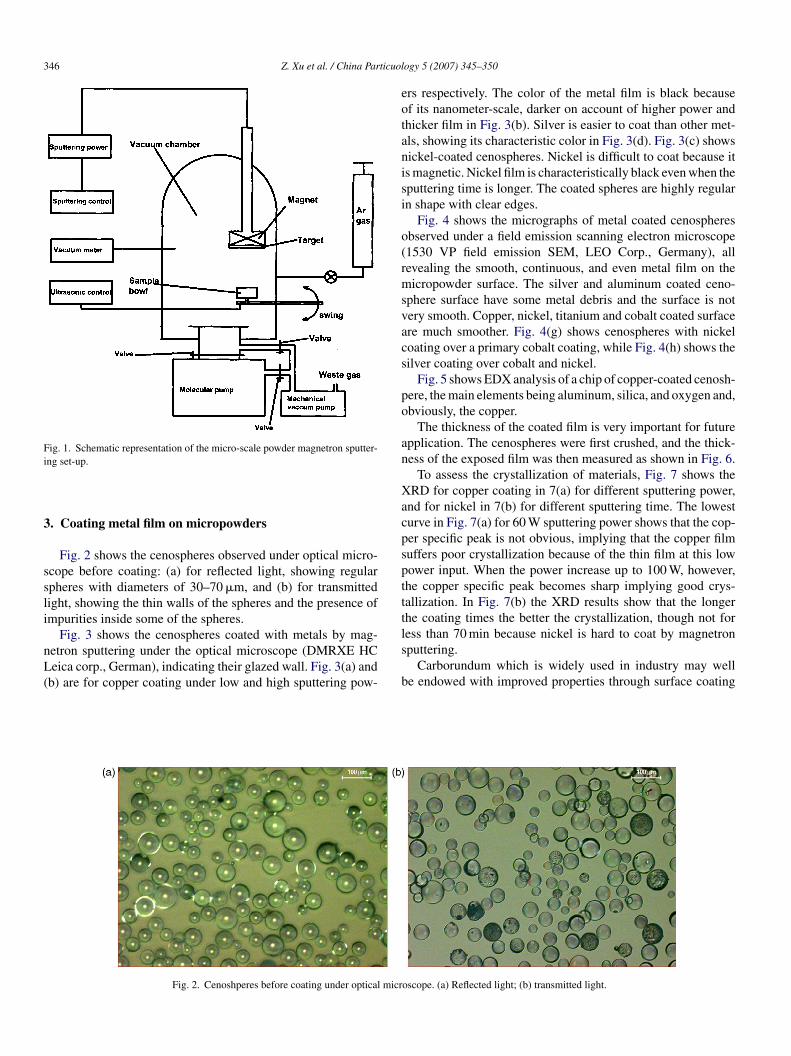
Fig. 1 shows the newly designed magnetron sputtering equip-ent used in the present work, consisting of a vacuum chamber,
he target, a sample shelf, a sample container, a heater, a rotaryump, a turbo-molecular pump, argon gas supply and a vibra-ion generator. Washed and dried micropowder, e.g. 2 g, waslaced in the sample container. The sputtering chamber wasvacuated to 3 × 10⁻³ Pa, and the sample container was vibratedt 600–1800 Hz to disperse the particles. In coating the particles,ome metal, e.g. silver, could make the coated cenosphere sticky,hile others, e.g. nickel and copper tended to better disperse
he coated cenospheres. Sputtering began after charging argon
t a vacuum of 4 × 10⁻¹ Pa. Sputtering power was adjustedy changing the sputtering voltage and the sputtering cur-ent. The sputtering time is determined by the thickness of theesulting metal film. The sample container could be heated ifecessary.Engineering, Chinese Academy of Sciences. Published by Elsevier B.V. All rights reserved.
346 Z. Xu et al. / China Particuol
Fig. 1. Schematic representation of the micro-scale powder magnetron sputter-i
3
ssli
nL(
eotanisi
o(rmsvacs
po
an
Xacpspttt
ng set-up.
. Coating metal film on micropowders
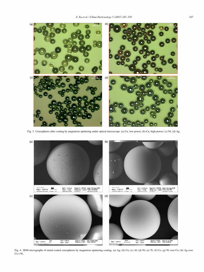
Fig. 2 shows the cenospheres observed under optical micro-cope before coating: (a) for reflected light, showing regularpheres with diameters of 30–70 �m, and (b) for transmittedight, showing the thin walls of the spheres and the presence ofmpurities inside some of the spheres.
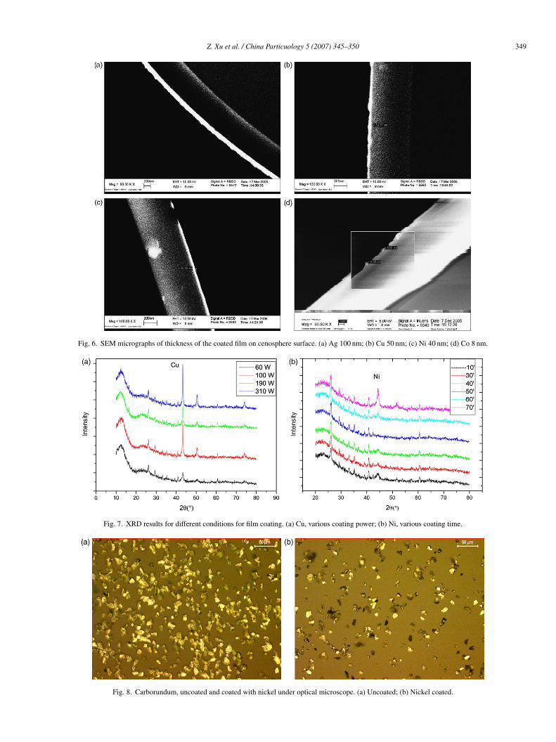
Fig. 3 shows the cenospheres coated with metals by mag-etron sputtering under the optical microscope (DMRXE HCeica corp., German), indicating their glazed wall. Fig. 3(a) and
b) are for copper coating under low and high sputtering pow-
ls
b
Fig. 2. Cenoshperes before coating under optical micr
ogy 5 (2007) 345–350
rs respectively. The color of the metal film is black becausef its nanometer-scale, darker on account of higher power andhicker film in Fig. 3(b). Silver is easier to coat than other met-ls, showing its characteristic color in Fig. 3(d). Fig. 3(c) showsickel-coated cenospheres. Nickel is difficult to coat because its magnetic. Nickel film is characteristically black even when theputtering time is longer. The coated spheres are highly regularn shape with clear edges.
Fig. 4 shows the micrographs of metal coated cenospheresbserved under a field emission scanning electron microscope1530 VP field emission SEM, LEO Corp., Germany), allevealing the smooth, continuous, and even metal film on theicropowder surface. The silver and aluminum coated ceno-
phere surface have some metal debris and the surface is notery smooth. Copper, nickel, titanium and cobalt coated surfacere much smoother. Fig. 4(g) shows cenospheres with nickeloating over a primary cobalt coating, while Fig. 4(h) shows theilver coating over cobalt and nickel.
Fig. 5 shows EDX analysis of a chip of copper-coated cenosh-ere, the main elements being aluminum, silica, and oxygen and,bviously, the copper.
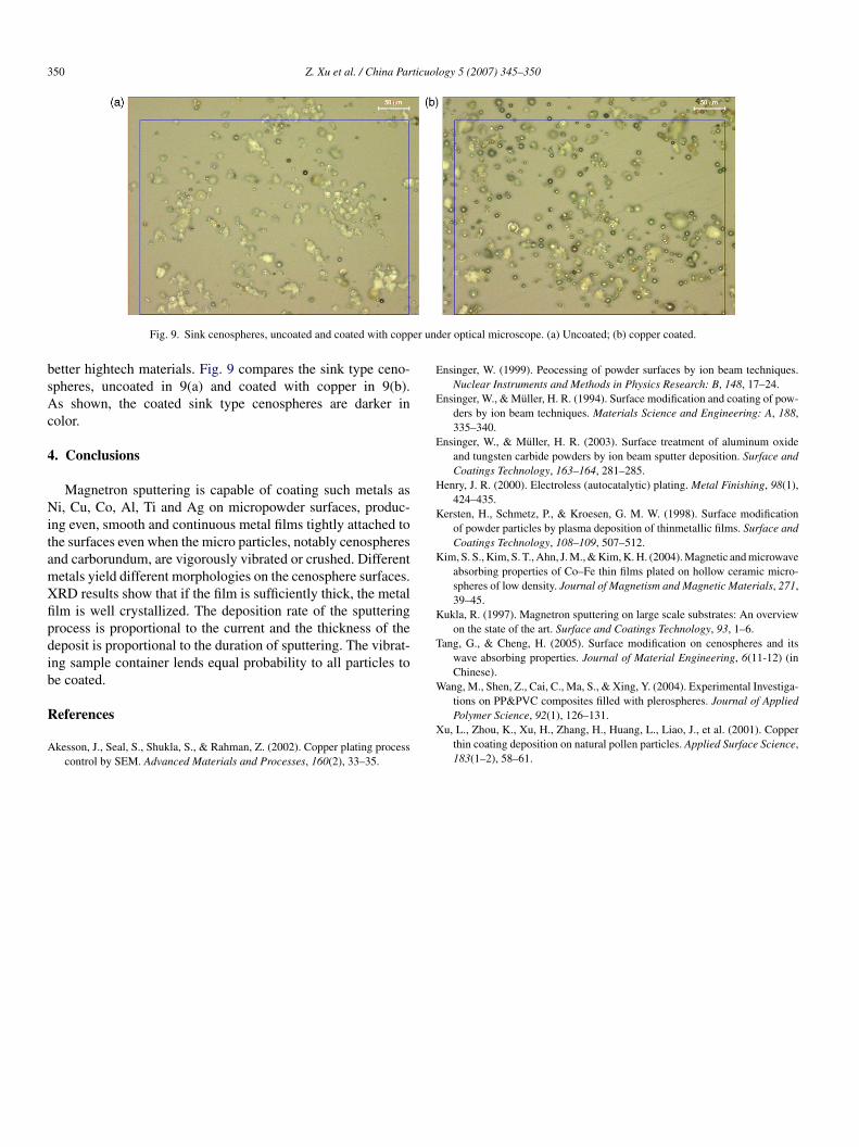
The thickness of the coated film is very important for futurepplication. The cenospheres were first crushed, and the thick-ess of the exposed film was then measured as shown in Fig. 6.
To assess the crystallization of materials, Fig. 7 shows theRD for copper coating in 7(a) for different sputtering power,
nd for nickel in 7(b) for different sputtering time. The lowesturve in Fig. 7(a) for 60 W sputtering power shows that the cop-er specific peak is not obvious, implying that the copper filmuffers poor crystallization because of the thin film at this lowower input. When the power increase up to 100 W, however,he copper specific peak becomes sharp implying good crys-allization. In Fig. 7(b) the XRD results show that the longerhe coating times the better the crystallization, though not for
ess than 70 min because nickel is hard to coat by magnetronputtering.Carborundum which is widely used in industry may welle endowed with improved properties through surface coating
oscope. (a) Reflected light; (b) transmitted light.
Z. Xu et al. / China Particuology 5 (2007) 345–350 347
Fig. 3. Cenospheres after coating by magnetron sputtering under optical microscope. (a) Cu, low power; (b) Cu, high power; (c) Ni; (d) Ag.
Fig. 4. SEM micrographs of metal-coated cenospheres by magnetron sputtering coating. (a) Ag; (b) Cu; (c) Al; (d) Ni; (e) Ti; (f) Co; (g) Ni over Co; (h) Ag overCo + Ni.

348 Z. Xu et al. / China Particuology 5 (2007) 345–350
( Cont
wucb
Fig. 4.
ith metal. Fig. 8 compares 10 �m carborundum microparticles,
ncoated in (a) and coated with nickel in (b). The uncoatedarborundum in Fig. 8(a) is yellow and dark green, but becomeslack when coated with nickel as shown in Fig. 8(b).tat
Fig. 5. SEM micrographs of EDX analysis of copper-coated film. (a) Chip of
inued ).
There are two types of cenospheres according to their par-
icle density: the lighter and less dense which float on waternd the heavier and denser which sink in water. The sinkype is generally finer in particle size, and promises to makecopper-coated cenosphere; (b) EDX analysis of chip shown on the left.
Z. Xu et al. / China Particuology 5 (2007) 345–350 349
Fig. 6. SEM micrographs of thickness of the coated film on cenosphere surface. (a) Ag 100 nm; (b) Cu 50 nm; (c) Ni 40 nm; (d) Co 8 nm.
Fig. 7. XRD results for different conditions for film coating. (a) Cu, various coating power; (b) Ni, various coating time.
Fig. 8. Carborundum, uncoated and coated with nickel under optical microscope. (a) Uncoated; (b) Nickel coated.
350 Z. Xu et al. / China Particuology 5 (2007) 345–350
er un
bsAc
4
NitamXfipdib
R
A
E
E
E
H
K
K
K
T
W
Fig. 9. Sink cenospheres, uncoated and coated with copp
etter hightech materials. Fig. 9 compares the sink type ceno-pheres, uncoated in 9(a) and coated with copper in 9(b).s shown, the coated sink type cenospheres are darker in
olor.
. Conclusions
Magnetron sputtering is capable of coating such metals asi, Cu, Co, Al, Ti and Ag on micropowder surfaces, produc-
ng even, smooth and continuous metal films tightly attached tohe surfaces even when the micro particles, notably cenospheresnd carborundum, are vigorously vibrated or crushed. Differentetals yield different morphologies on the cenosphere surfaces.RD results show that if the film is sufficiently thick, the metallm is well crystallized. The deposition rate of the sputteringrocess is proportional to the current and the thickness of theeposit is proportional to the duration of sputtering. The vibrat-ng sample container lends equal probability to all particles toe coated.
eferences
kesson, J., Seal, S., Shukla, S., & Rahman, Z. (2002). Copper plating processcontrol by SEM. Advanced Materials and Processes, 160(2), 33–35.
X
der optical microscope. (a) Uncoated; (b) copper coated.
nsinger, W. (1999). Peocessing of powder surfaces by ion beam techniques.Nuclear Instruments and Methods in Physics Research: B, 148, 17–24.
nsinger, W., & Muller, H. R. (1994). Surface modification and coating of pow-ders by ion beam techniques. Materials Science and Engineering: A, 188,335–340.
nsinger, W., & Muller, H. R. (2003). Surface treatment of aluminum oxideand tungsten carbide powders by ion beam sputter deposition. Surface andCoatings Technology, 163–164, 281–285.
enry, J. R. (2000). Electroless (autocatalytic) plating. Metal Finishing, 98(1),424–435.
ersten, H., Schmetz, P., & Kroesen, G. M. W. (1998). Surface modificationof powder particles by plasma deposition of thinmetallic films. Surface andCoatings Technology, 108–109, 507–512.
im, S. S., Kim, S. T., Ahn, J. M., & Kim, K. H. (2004). Magnetic and microwaveabsorbing properties of Co–Fe thin films plated on hollow ceramic micro-spheres of low density. Journal of Magnetism and Magnetic Materials, 271,39–45.
ukla, R. (1997). Magnetron sputtering on large scale substrates: An overviewon the state of the art. Surface and Coatings Technology, 93, 1–6.
ang, G., & Cheng, H. (2005). Surface modification on cenospheres and itswave absorbing properties. Journal of Material Engineering, 6(11-12) (inChinese).
ang, M., Shen, Z., Cai, C., Ma, S., & Xing, Y. (2004). Experimental Investiga-
tions on PP&PVC composites filled with plerospheres. Journal of AppliedPolymer Science, 92(1), 126–131.u, L., Zhou, K., Xu, H., Zhang, H., Huang, L., Liao, J., et al. (2001). Copperthin coating deposition on natural pollen particles. Applied Surface Science,183(1–2), 58–61.