com express module c o m - h m 7 6
TRANSCRIPT

COM Express Module C O M - H M 7 6
COM-HM76
3rd Generation Intel® Core™ i7/i5/i3
Processor
Intel® HM76
Gigabit Ethernet
4 SATA
8 USB2.0, up to 4 USB3.0
1 PCI-E[x16], 7 PCI-E[x1]
COM Express Basic Module
COM-HM76 Manual Rev.A 1st Ed.
May 14, 2014

COM Express Module C O M - H M 7 6
i
Copyright Notice
This document is copyrighted, 2014. All rights are reserved. The original manufacturer reserves the right to make improvements to the products described in this manual at any time without notice.
No part of this manual may be reproduced, copied, translated, or transmitted in any form or by any means without the prior written permission of the original manufacturer. Information provided in this manual is intended to be accurate and reliable. However, the original manufacturer assumes no responsibility for its use, or for any in-fringements upon the rights of third parties that may result from its use.
The material in this document is for product information only and is subject to change without notice. While reasonable efforts have been made in the preparation of this document to assure its accuracy, AAEON assumes no liabilities resulting from errors or omissions in this document, or from the use of the information contained herein.
AAEON reserves the right to make changes in the product design without notice to its users.

COM Express Module C O M - H M 7 6
ii
Acknowledgments
All other products’ name or trademarks are properties of their respective owners.
AMI is a trademark of American Megatrends Inc.
Intel®, Core™ are trademarks of Intel
® Corporation.
Microsoft Windows®
is a registered trademark of Microsoft Corp.
ITE is a trademark of Integrated Technology Express, Inc.
IBM, PC/AT, PS/2, and VGA are trademarks of International
Business Machines Corporation.
SoundBlaster is a trademark of Creative Labs, Inc.
All other product names or trademarks are properties of their respective owners.
COM Express Module C O M - H M 7 6
iii
Packing List
Before you begin installing your card, please make sure that the following materials have been shipped:
4 M2.5 Screw
1 DVD-ROM for manual (in PDF format) and
drivers
1 COM-HM76
If any of these items should be missing or damaged, please contact your distributor or sales representative immediately.
COM Express Module C O M - H M 7 6
iv
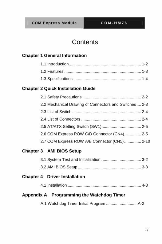
Contents
Chapter 1 General Information
1.1 Introduction ................................................................ 1-2
1.2 Features .................................................................... 1-3
1.3 Specifications ............................................................ 1-4
Chapter 2 Quick Installation Guide
2.1 Safety Precautions .................................................... 2-2
2.2 Mechanical Drawing of Connectors and Switches .... 2-3
2.3 List of Switch ............................................................. 2-4
2.4 List of Connectors ..................................................... 2-4
2.5 AT/ATX Setting Switch (SW1) ................................... 2-5
2.6 COM Express ROW C/D Connector (CN4)............... 2-5
2.7 COM Express ROW A/B Connector (CN5) ............... 2-10
Chapter 3 AMI BIOS Setup
3.1 System Test and Initialization. .................................. 3-2
3.2 AMI BIOS Setup ........................................................ 3-3
Chapter 4 Driver Installation
4.1 Installation ................................................................. 4-3
Appendix A Programming the Watchdog Timer
A.1 Watchdog Timer Initial Program ............................ A-2

COM Express Module C O M - H M 7 6
v
Appendix B I/O Information
B.1 I/O Address Map .................................................... B-2
B.2 Memory Address Map ............................................ B-4
B.3 IRQ Mapping Chart ................................................ B-5
B.4 DMA Channel Assignments ................................... B-7
Appendix C RAID & AHCI Settings
C.1 Setting AHCI ......................................................... C-2
Appendix D Programming the Digital I/O
D.1 DIO Programming ................................................. D-2
D.2 Digital I/O Register ................................................ D-3
D.3 Digital I/O Sample Program .................................. D-4

COM Express Module C O M - H M 7 6
Chapter 1 General Information 1- 1
General Information
Chapter
1
COM Express Module C O M - H M 7 6
Chapter 1 General Information 1- 2
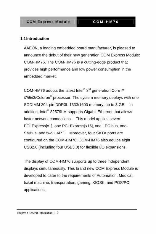
1.1 Introduction
AAEON, a leading embedded board manufacturer, is pleased to
announce the debut of their new generation COM Express Module:
COM-HM76. The COM-HM76 is a cutting-edge product that
provides high performance and low power consumption in the
embedded market.
COM-HM76 adopts the latest Intel® 3
rd generation Core™
i7/i5/i3/Celeron® processor. The system memory deploys with one
SODIMM 204-pin DDR3L 1333/1600 memory, up to 8 GB. In
addition, Intel® 82579LM supports Gigabit Ethernet that allows
faster network connections. This model applies seven
PCI-Express[x1], one PCI-Express[x16], one LPC bus, one
SMBus, and two UART. Moreover, four SATA ports are
configured on the COM-HM76. COM-HM76 also equips eight
USB2.0 (including four USB3.0) for flexible I/O expansions.
The display of COM-HM76 supports up to three independent
displays simultaneously. This brand new COM Express Module is
developed to cater to the requirements of Automation, Medical,
ticket machine, transportation, gaming, KIOSK, and POS/POI
applications.

COM Express Module C O M - H M 7 6
Chapter 1 General Information 1 - 3
1.2 Features
Onboard 3rd Generation Intel® Core™ i7/ i5/ i3 Processor
Intel® HM76 PCH
Single Channel SODIMM DDR3L 1333/1600 Memory,
Max.8 GB
Gigabit Ethernet
VGA x 1, DDI x 2, LVDS x 1 (18/24-bit
Dual-channel LVDS LCD)
High Definition Audio Interface
SATA x 4
USB2.0 x 8 (Including USB3.0 x 4)
PCI-Express [x16] x 1 (Gen. 3.0), PCI-Express [x1] x 7
(Gen. 2.0)
Note: Configurable to PCI-Express[x8] Port x 2; Configurable to
PCI-Express[x8] Port x 1 and PCI-Express[x4] Port x 2
DC Input Range, +12V
COM Express Basic Module, Pin-out Type 6, COM.0 Rev.
2.1

COM Express Module C O M - H M 7 6
Chapter 1 General Information 1- 4
1.3 Specifications
System
Form Factor COM Express Basic module, Pin-out Type 6, COM. 0 Rev. 2.1
Processor Onboard 3rd Generation Intel® Core™
i7/i5/i3 Processor
System Memory 204-pin DDR3L SODIMM x 1, Max. 8GB (DDR3L 1333/1600), supports single channel function
Chipset Intel® HM76
I/O Chipset Intel® HM76 (Winbond SIO on the carrier
board)
Ethernet Intel® 82579LM, 10/100/1000Base-TX
PHY
BIOS AMI BIOS
SPI type
EEPROM FMD. FT24C02A, save BIOS and configuration data
Wake On LAN Yes
BBS (BIOS Boot Spec.)
Yes
Watchdog Timer ITE8518, 255 levels
H/W Status Monitoring
Supports CPU Temperature Monitoring
Expansion Interface PCI-Express [x16] x 1
PCI-Express [x1] x 7
LPC bus x 1
SMBus x 1
UART x 2 (TX/RX only)
Power Requirement +12V only
2-pin wafer for RTC battery

COM Express Module C O M - H M 7 6
Chapter 1 General Information 1 - 5
Board Size 4.92" (L) x 3.75"(W) (125mm x 95mm)
Gross Weight 0.66lb (0.3kg)
Operating Temperature
32°F ~ 140°F (0°C ~ 60°C)
Storage Temperature -40°F ~ 176°F (-40°C ~ 80°C)
Operating Humidity 0% ~ 90% relative humidity, non-condensing
OS Support Windows® 7, Windows
® 8, Linux Fedora 16
Display
Chipset 3rd Generation Intel® Core™ i7/i5/i3
Processor Integrated
Memory Shared system memory up to 512MB/ DVMT 5.0
Resolution Up to 2560 x 2048 for CRT
Up to 1920 x 1200 for LVDS
LCD Interface Up to 24-bit dual-channel LVDS, VGA
I/O
Storage SATA x 4
Serial Port From LPC to EC, then to the carrier board (EC x 2)
USB USB2.0 x 8 (including USB 3.0 x 4)
Audio High definition audio
GPIO Up to 4 in and 4 out

COM Express Module C O M - H M 7 6
Chapter 2 Quick Installation Guide 2-1
Quick Installation
Guide
Chapter
2

COM Express Module C O M - H M 7 6
Chapter 2 Quick Installation Guide 2 - 2
2.1 Safety Precautions
Always completely disconnect the power cord from your board whenever you are working on it. Do not make connections while the power is on, because a sudden rush of power can damage sensitive electronic components.
Always ground yourself to remove any static charge before touching the board. Modern electronic devices are very sensitive to static electric charges. Use a grounding wrist strap at all times. Place all electronic components on a static-dissipative surface or in a static-shielded bag when they are not in the chassis

COM Express Module C O M - H M 7 6
Chapter 2 Quick Installation Guide 2 - 3
2.2 Mechanical Drawings of Connectors and Switches
Component Side
NA
T=2.0MM
PCB
11R 0.2
COM-HM76
PCB_DRAWING
Peter.K Ryo
COM-HM76
COM-HM76
Component Side Solder Side
Solder Side
NA
T=2.0MM
PCB
11R 0.2
COM-HM76
PCB_DRAWING
Peter.K Ryo
COM-HM76
COM-HM76
Component Side Solder Side

COM Express Module C O M - H M 7 6
Chapter 2 Quick Installation Guide 2 - 4
2.3 List of Switch
There is a switch on the board that allows you to configure your
system to suit your application. The table below shows the function
of the switch.
Label Function
SW1 AT/ATX Setting Switch
2.4 List of Connectors
There are a number of connectors of the board that allow you to
configure your system to suit your application. The table below
shows the function of each connector in the board:
Label Function
DIMM1 SODIMM COM
CN3 RTC Battery Connector
CN4 Express ROW C/D Connector
CN5 Express ROW A/B Connector
CN6 RSVD Connector
CN7 SPI Flash Programming Connector
CN8 LPC Debug Card Connector
COM Express Module C O M - H M 7 6
Chapter 2 Quick Installation Guide 2 - 5
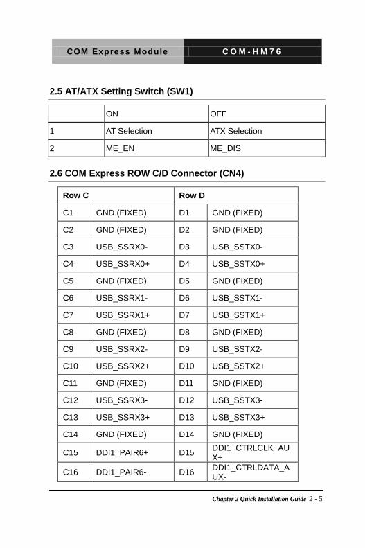
2.5 AT/ATX Setting Switch (SW1)
ON OFF
1 AT Selection ATX Selection
2 ME_EN ME_DIS
2.6 COM Express ROW C/D Connector (CN4)
Row C Row D
C1 GND (FIXED) D1 GND (FIXED)
C2 GND (FIXED) D2 GND (FIXED)
C3 USB_SSRX0- D3 USB_SSTX0-
C4 USB_SSRX0+ D4 USB_SSTX0+
C5 GND (FIXED) D5 GND (FIXED)
C6 USB_SSRX1- D6 USB_SSTX1-
C7 USB_SSRX1+ D7 USB_SSTX1+
C8 GND (FIXED) D8 GND (FIXED)
C9 USB_SSRX2- D9 USB_SSTX2-
C10 USB_SSRX2+ D10 USB_SSTX2+
C11 GND (FIXED) D11 GND (FIXED)
C12 USB_SSRX3- D12 USB_SSTX3-
C13 USB_SSRX3+ D13 USB_SSTX3+
C14 GND (FIXED) D14 GND (FIXED)
C15 DDI1_PAIR6+ D15 DDI1_CTRLCLK_AUX+
C16 DDI1_PAIR6- D16 DDI1_CTRLDATA_AUX-

COM Express Module C O M - H M 7 6
Chapter 2 Quick Installation Guide 2 - 6
C17 RSVD D17 RSVD
C18 RSVD D18 RSVD
C19 PCIE_RX6+ D19 PCIE_TX6+
C20 PCIE_RX6- D20 PCIE_TX6-
C21 GND (FIXED) D21 GND (FIXED)
C22 PCIE_RX7+ D22 PCIE_TX7+
C23 PCIE_RX7- D23 PCIE_TX7-
C24 DDI1_HPD D24 RSVD
C25 DDI1_PAIR4+ D25 RSVD
C26 DDI1_PAIR4- D26 DDI1_PAIR0+
C27 RSVD D27 DDI1_PAIR0-
C28 RSVD D28 RSVD
C29 DDI1_PAIR5+ D29 DDI1_PAIR1+
C30 DDI1_PAIR5- D30 DDI1_PAIR1-
C31 GND (FIXED) D31 GND (FIXED)
C32 DDI2_CTRLCLK_AUX+
D32 DDI1_PAIR2+
C33 DDI2_CTRLDATA_AUX-
D33 DDI1_PAIR2-
C34 DDI2_DDC_AUX_SEL
D34 DDI1_DDC_AUX_SEL
C35 RSVD D35 RSVD
C36 DDI3_CTRLCLK_AUX+
D36 DDI1_PAIR3+
C37 DDI3_CTRLDATA_AUX-
D37 DDI1_PAIR3-
C38 DDI3_DDC_AUX_SEL
D38 RSVD
C39 DDI3_PAIR0+ D39 DDI2_PAIR0+

COM Express Module C O M - H M 7 6
Chapter 2 Quick Installation Guide 2 - 7
C40 DDI3_PAIR0- D40 DDI2_PAIR0-
C41 GND (FIXED) D41 GND (FIXED)
C42 DDI3_PAIR1+ D42 DDI2_PAIR1+
C43 DDI3_PAIR1- D43 DDI2_PAIR1-
C44 DDI3_HPD D44 DDI2_HPD
C45 RSVD D45 RSVD
C46 DDI3_PAIR2+ D46 DDI2_PAIR2+
C47 DDI3_PAIR2- D47 DDI2_PAIR2-
C48 RSVD D48 RSVD
C49 DDI3_PAIR3- D49 DDI2_PAIR3+
C50 DDI3_PAIR3- D50 DDI2_PAIR3-
C51 GND (FIXED) D51 GND (FIXED)
C52 PEG_RX0+ D52 PEG_TX0+
C53 PEG_RX0- D53 PEG_TX0-
C54 TYPE0# D54 PEG_LAN_RV#
C55 PEG_RX1+ D55 PEG_TX1+
C56 PEG_RX1- D56 PEG_TX1-
C57 TYPE1# D57 TYPE2#
C58 PEG_RX2+ D58 PEG_TX2+
C59 PEG_RX2- D59 PEG_TX2-
C60 GND (FIXED) D60 GND (FIXED)
C61 PEG_RX3+ D61 PEG_TX3+
C62 PEG_RX3- D62 PEG_TX3-
C63 RSVD D63 RSVD

COM Express Module C O M - H M 7 6
Chapter 2 Quick Installation Guide 2 - 8
C64 RSVD D64 RSVD
C65 PEG_RX4+ D65 PEG_TX4+
C66 PEG_RX4- D66 PEG_TX4-
C67 RSVD D67 GND (FIXED)
C68 PEG_RX5+ D68 PEG_TX5+
C69 PEG_RX5- D69 PEG_TX5-
C70 GND (FIXED) D70 GND (FIXED)
C71 PEG_RX6+ D71 PEG_TX6+
C72 PEG_RX6- D72 PEG_TX6-
C73 GND (FIXED) D73 GND (FIXED)
C74 PEG_RX7+ D74 PEG_TX7+
C75 PEG_RX7- D75 PEG_TX7-
C76 GND (FIXED) D76 GND (FIXED)
C77 RSVD D77 RSVD
C78 PEG_RX8+ D78 PEG_TX8+
C79 PEG_RX8- D79 PEG_TX8-
C80 GND (FIXED) D80 GND (FIXED)
C81 PEG_RX9+ D81 PEG_TX9+
C82 PEG_RX9- D82 PEG_TX9-
C83 RSVD D83 RSVD
C84 GND (FIXED) D84 GND (FIXED)
C85 PEG_RX10+ D85 PEG_TX10+
C86 PEG_RX10- D86 PEG_TX10-
C87 GND (FIXED) D87 GND (FIXED)
COM Express Module C O M - H M 7 6
Chapter 2 Quick Installation Guide 2 - 9
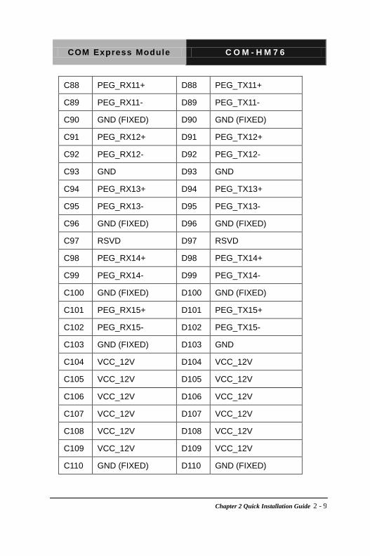
C88 PEG_RX11+ D88 PEG_TX11+
C89 PEG_RX11- D89 PEG_TX11-
C90 GND (FIXED) D90 GND (FIXED)
C91 PEG_RX12+ D91 PEG_TX12+
C92 PEG_RX12- D92 PEG_TX12-
C93 GND D93 GND
C94 PEG_RX13+ D94 PEG_TX13+
C95 PEG_RX13- D95 PEG_TX13-
C96 GND (FIXED) D96 GND (FIXED)
C97 RSVD D97 RSVD
C98 PEG_RX14+ D98 PEG_TX14+
C99 PEG_RX14- D99 PEG_TX14-
C100 GND (FIXED) D100 GND (FIXED)
C101 PEG_RX15+ D101 PEG_TX15+
C102 PEG_RX15- D102 PEG_TX15-
C103 GND (FIXED) D103 GND
C104 VCC_12V D104 VCC_12V
C105 VCC_12V D105 VCC_12V
C106 VCC_12V D106 VCC_12V
C107 VCC_12V D107 VCC_12V
C108 VCC_12V D108 VCC_12V
C109 VCC_12V D109 VCC_12V
C110 GND (FIXED) D110 GND (FIXED)

COM Express Module C O M - H M 7 6
Chapter 2 Quick Installation Guide 2 - 10
2.7 COM Express ROW A/B Connector (CN5)
Row A Row B
A1 GND (FIXED) B1 GND (FIXED)
A2 GBE0_MDI3- B2 GBE0_ACT#
A3 GBE0_MDI3+ B3 LPC_FRAME#
A4 GBE0_LINK100# B4 LPC_AD0
A5 GBE0_LINK1000# B5 LPC_AD1
A6 GBE0_MDI2- B6 LPC_AD2
A7 GBE0_MDI2+ B7 LPC_AD3
A8 GBE0_LINK B8 LPC_DRQ0#
A9 GBE0_MDI1- B9 LPC_DRQ1#
A10 GBE0_MDI1+ B10 LPC_CLK
A11 GND (FIXED) B11 GND (FIXED)
A12 GBE0_MDI0- B12 PWRBTN#
A13 GBE0_MDI0+ B13 SMB_CK
A14 GBE0_CTREF B14 SMB_DAT
A15 SUS_S3# B15 SMB_ALERT#
A16 SATA0_TX+ B16 SATA1_TX+
A17 SATA0_TX- B17 SATA1_TX-
A18 SUS_S4# B18 SUS_STAT#
A19 SATA0_RX+ B19 SATA1_RX+
A20 SATA0_RX- B20 SATA1_RX-
A21 GND (FIXED) B21 GND (FIXED)

COM Express Module C O M - H M 7 6
Chapter 2 Quick Installation Guide 2 - 11
A22 SATA2_TX+ B22 SATA3_TX+
A23 SATA2_TX- B23 SATA3_TX-
A24 SUS_S5# B24 PWR_OK
A25 SATA2_RX+ B25 SATA3_RX+
A26 SATA2_RX- B26 SATA3_RX-
A27 BATLOW# B27 WDT
A28 ATA_ACT# B28 AC_SDIN2
A29 AC_SYNC B29 AC_SDIN1
A30 AC_RST# B30 AC_SDIN0
A31 GND (FIXED) B31 GND (FIXED)
A32 AC_BITCLK B32 SPKR
A33 AC_SDOUT B33 I2C_CK
A34 BIOS_DIS0# B34 I2C_DAT
A35 THRMTRIP# B35 THRM#
A36 USB6- B36 USB7-
A37 USB6+ B37 USB7+
A38 USB_6_7_OC# B38 USB_4_5_OC#
A39 USB4- B39 USB5-
A40 USB4+ B40 USB5+
A41 GND (FIXED) B41 GND (FIXED)
A42 USB2- B42 USB3-
A43 USB2+ B43 USB3+
A44 USB_2_3_OC# B44 USB_0_1_OC#
A45 USB0- B45 USB1-

COM Express Module C O M - H M 7 6
Chapter 2 Quick Installation Guide 2 - 12
A46 USB0+ B46 USB1+
A47 VCC_RTC B47 EXCD1_PERST#
A48 EXCD0_PERST# B48 EXCD1_CPPE#
A49 EXCD0_CPPE# B49 SYS_RESET#
A50 LPC_SERIRQ B50 CB_RESET#
A51 GND (FIXED) B51 GND (FIXED)
A52 PCIE_TX5+ B52 PCIE_RX5+
A53 PCIE_TX5- B53 PCIE_RX5-
A54 GPI0 B54 GPO1
A55 PCIE_TX4+ B55 PCIE_RX4+
A56 PCIE_TX4- B56 PCIE_RX4-
A57 GND B57 GPO2
A58 PCIE_TX3+ B58 PCIE_RX3+
A59 PCIE_TX3- B59 PCIE_RX3-
A60 GND (FIXED) B60 GND (FIXED)
A61 PCIE_TX2+ B61 PCIE_RX2+
A62 PCIE_TX2- B62 PCIE_RX2-
A63 GPI1 B63 GPO3
A64 PCIE_TX1+ B64 PCIE_RX1+
A65 PCIE_TX1- B65 PCIE_RX1-
A66 GND B66 WAKE0#
A67 GPI2 B67 WAKE1#
A68 PCIE_TX0+ B68 PCIE_RX0+
A69 PCIE_TX0- B69 PCIE_RX0-

COM Express Module C O M - H M 7 6
Chapter 2 Quick Installation Guide 2 - 13
A70 GND (FIXED) B70 GND (FIXED)
A71 LVDS_A0+ B71 LVDS_B0+
A72 LVDS_A0- B72 LVDS_B0-
A73 LVDS_A1+ B73 LVDS_B1+
A74 LVDS_A1- B74 LVDS_B1-
A75 LVDS_A2+ B75 LVDS_B2+
A76 LVDS_A2- B76 LVDS_B2-
A77 LVDS_VDD_EN B77 LVDS_B3+
A78 LVDS_A3+ B78 LVDS_B3-
A79 LVDS_A3- B79 LVDS_BKLT_EN
A80 GND (FIXED) B80 GND (FIXED)
A81 LVDS_A_CK+ B81 LVDS_B_CK+
A82 LVDS_A_CK- B82 LVDS_B_CK-
A83 LVDS_I2C_CK B83 LVDS_BKLT_CTRL
A84 LVDS_I2C_DAT B84 VCC_5V_SBY
A85 GPI3 B85 VCC_5V_SBY
A86 RSVD B86 VCC_5V_SBY
A87 RSVD B87 VCC_5V_SBY
A88 PCIE0_CK_REF+ B88 BISO_DIS1#
A89 PCIE0_CK_REF- B89 VGA_RED
A90 GND (FIXED) B90 GND (FIXED)
A91 SPI _POWER B91 VGA_GRN
A92 SPI_MISO B92 VGA_BLU
A93 GPO0 B93 VGA_HSYNC

COM Express Module C O M - H M 7 6
Chapter 2 Quick Installation Guide 2 - 14
A94 SPI_CLK B94 VGA_VSYNC
A95 SPI_MOSI B95 VGA_I2C_CK
A96 TPM_PP B96 VGA_I2C_DAT
A97 TYPE10# B97 SPI_CS#
A98 SER0_TX B98 RSVD
A99 SER0_RX B99 RSVD
A100 GND (FIXED) B100 GND (FIXED)
A101 SER1_TX B101 FAN_PWNOUT
A102 SER1_RX B102 FAN_TACHIN
A103 LID# B103 SLEEP#
A104 VCC_12V B104 VCC_12V
A105 VCC_12V B105 VCC_12V
A106 VCC_12V B106 VCC_12V
A107 VCC_12V B107 VCC_12V
A108 VCC_12V B108 VCC_12V
A109 VCC_12V B109 VCC_12V
A110 GND (FIXED) B110 GND (FIXED)

COM Express Module C O M - H M 7 6
Chapter 2 Quick Installation Guide 2 - 15
Below Table for China RoHS Requirements
产品中有毒有害物质或元素名称及含量
AAEON Main Board/ Daughter Board/ Backplane
部件名称
有毒有害物质或元素
铅
(Pb)
汞
(Hg)
镉
(Cd)
六价铬
(Cr(VI))
多溴联苯
(PBB)
多溴二苯醚
(PBDE)
印刷电路板
及其电子组件 × ○ ○ ○ ○ ○
外部信号
连接器及线材 × ○ ○ ○ ○ ○
O:表示该有毒有害物质在该部件所有均质材料中的含量均在
SJ/T 11363-2006 标准规定的限量要求以下。
X:表示该有毒有害物质至少在该部件的某一均质材料中的含量超出
SJ/T 11363-2006 标准规定的限量要求。
备注:此产品所标示之环保使用期限,系指在一般正常使用状况下。

COM Express Module C O M - H M 7 6
Chapter 3 AMI BIOS Setup 3-1
AMI BIOS Setup
Chapter
3

COM Express Module C O M - H M 7 6
Chapter 3 AMI BIOS Setup 3-2
3.1 System Test and Initialization
These routines test and initialize board hardware. If the routines
encounter an error during these tests, you will either hear a few
short beeps or see an error message on the screen. There are two
kinds of errors: fatal or non-fatal. The system can usually continue
the boot up sequence with non-fatal errors.
System configuration verification
These routines check the current system configuration stored in the
CMOS memory and BIOS NVRAM. If system configuration is not
found or system configuration data error is detected, system will
load optimized default and re-boot with this default system
configuration automatically.
There are four situations in which you will need to setup system
configuration:
1. You are starting your system for the first time
2. You have changed the hardware attached to your system
3. The system configuration is reset by Clear-CMOS jumper
4. The CMOS memory has lost power and the configuration
information has been erased.
The COM-HM76 CMOS memory has an integral lithium battery
backup for data retention. However, you will need to replace the

COM Express Module C O M - H M 7 6
Chapter 3 AMI BIOS Setup 3-3
complete unit when it finally runs down.
3.2 AMI BIOS Setup
AMI BIOS ROM has a built-in Setup program that allows users to
modify the basic system configuration. This type of information is
stored in battery-backed CMOS RAM and BIOS NVRAM so that it
retains the Setup information when the power is turned off.
Entering Setup
Power on the computer and press <Del> or <F2> immediately. This
will allow you to enter Setup.
Main
Set the date, use tab to switch between date elements.
Advanced
Enable disable boot option for legacy network devices.
Chipset
Host bridge parameters.
Boot
Enables/disable quiet boot option.
Security
Set setup administrator password.
Save&Exit
Exit system setup after saving the changes.

COM Express Module C O M - H M 7 6
Chapter 3 AMI BIOS Setup 3-4
Setup Menu
Setup submenu: Main

COM Express Module C O M - H M 7 6
Chapter 3 AMI BIOS Setup 3-5
Setup submenu: Advanced

COM Express Module C O M - H M 7 6
Chapter 3 AMI BIOS Setup 3-6
S5 RTC Wake Settings (Fixed Time)
Options summary:
Wake system with Fixed Time
Disabled Optimal Default, Failsafe Default
Enabled
En/Disable System wake on alarm event. When enabled, System will wake on the hr:min:sec specified
Wake up day 0-31 Default 0
Select 0 for daily system wake up, 1-31 for witch day of the moth that you would like the system to wake up.
Wake up day 0-23 Default 0
Select 0-23 For example enter 3 for 3am and 15 for 3pm
Wake up day 0-59 Default 0
Select 0-59
Wake up day 0-59 Default 0
Select 0-59

COM Express Module C O M - H M 7 6
Chapter 3 AMI BIOS Setup 3-7
S5 RTC Wake Settings (Dynamic Time)
Options summary:
Wake system with Dynamic Time
Disabled Optimal Default, Failsafe Default
Enabled
En/Disable System wake on alarm event. When enabled, System will wake on current time + Increases minutes(s)
Wake up day 1-5 Default 1
Select 1-5

COM Express Module C O M - H M 7 6
Chapter 3 AMI BIOS Setup 3-8
CPU Configuration

COM Express Module C O M - H M 7 6
Chapter 3 AMI BIOS Setup 3-9

COM Express Module C O M - H M 7 6
Chapter 3 AMI BIOS Setup 3-10
Option summary:
Hyper-Threading Disabled
Enabled Default
Enabled for Windows XP and Linux (OS optimized for Hyper-Threading Technology) and Disabled for other OS (OS not optimized for Hyper-Threading Technology). When Disabled only one thread per enabled core is enabled.
Active Processor Cores All Default
1
2
3
Number of cores to enable in each processor package.
Limit CPUID Maximum Disabled Default
Enabled
Disabled for Windows XP
Execute Disable Bit Disabled
Enabled Default
XD can prevent certain classes of malicious buffer overflow attacks when combined with a supporting OS (Windows Server 2003 SP1, Windows XP SP2, SuSE Linux 9.2, RedHat Enterprise 3 Update 3.)
Intel Virtualization Technology
Disabled Default
Enabled
When enabled, a VMM can utilize the additional hardware capabilities provided by Vanderpool Technology.
Hardware Prefetcher Disabled
Enabled Default
To turn on/off the Mid Level Cache (L2) streamer prefetcher.
Adjacent Cache Line Prefetch
Disabled
Enabled Default
To turn on/off prefetching of adjacent cache lines.
TCC Activation offset 0~50 Default (0)
When enabled, a VMM can utilize the additional hardware capabilities provided by Vanderpool Technology.
Primary Plane Current value
0~255 Default (0)
The Maximum instantaneous current allow for Primary Plane
Secondary Plane Current value
0~255 Default (0)
The Maximum instantaneous current allow for Secondary Plane
COM Express Module C O M - H M 7 6
Chapter 3 AMI BIOS Setup 3-11
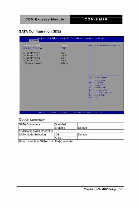
SATA Configuration (IDE)
Option summary:
SATA Controllers Disabled
Enabled Default
En/Disable SATA Controller.
SATA Mode Selection IDE Default
AHCI
Determines how SATA controller(s) operate.

COM Express Module C O M - H M 7 6
Chapter 3 AMI BIOS Setup 3-12
SATA Configuration (AHCI)
Option summary:
Hot Plug Disabled
Enabled Default
En/Disable Hot Plug feature.
Port 3 Disabled
Enabled Default
En/Disable SATA Port.

COM Express Module C O M - H M 7 6
Chapter 3 AMI BIOS Setup 3-13
USB Configuration
Option summary:
Legacy USB Support Enabled Default
Disabled
Auto
Enables BIOS Support for Legacy USB Support. When enabled, USB can be functional in legacy environment like DOS. AUTO option disables legacy support if no USB devices are connected
USB3.0 Support Enabled Default
Disabled
Enable/Disable USB3.0 (XHCI) Controller support.
COM Express Module C O M - H M 7 6
Chapter 3 AMI BIOS Setup 3-14
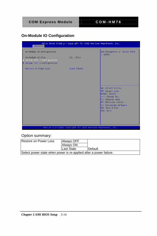
On-Module IO Configuration
Option summary:
Restore on Power Loss Always OFF
Always ON
Last State Default
Select power state when power is re-applied after a power failure.

COM Express Module C O M - H M 7 6
Chapter 3 AMI BIOS Setup 3-15
Serial Port Configuration
Option summary:
Serial Port Disabled
Enabled Default
Allows BIOS to En/Disable correspond serial port.
Change Settings Auto Default
IO=3F8h; IRQ=3;
IO=3F8h; IRQ= 3,4,5,6,7,10,11;
IO=2F8h; IRQ= 3,4,5,6,7,10,11;
IO=3E8h; IRQ= 3,4,5,6,7,10,11;
IO=2E8h; IRQ= 3,4,5,6,7,10,11;
Allows BIOS to Select Serial Port resource.

COM Express Module C O M - H M 7 6
Chapter 3 AMI BIOS Setup 3-16
Option summary:
Serial Port Disabled
Enabled Default
Allows BIOS to En/Disable correspond serial port.
Change Settings
Auto Default
IO=2F8h; IRQ=4;
IO=3F8h; IRQ= 3,4,5,6,7,10,11;
IO=2F8h; IRQ= 3,4,5,6,7,10,11;
IO=3E8h; IRQ= 3,4,5,6,7,10,11;
IO=2E8h; IRQ= 3,4,5,6,7,10,11;

COM Express Module C O M - H M 7 6
Chapter 3 AMI BIOS Setup 3-17
On-Module H/W Monitor

COM Express Module C O M - H M 7 6
Chapter 3 AMI BIOS Setup 3-18
Smart Fan Mode Configuration
Option summary:
CPU Smart Fan Control Full Mode
Manual Mode by PWM Default
Auto Mode by PWM
Select CPU Fan control mode
Manual Setting 70 (0 - 100) Default
Set Fan at fixed Duty-Cycle Min=0 Max=100 Please input Dec number

COM Express Module C O M - H M 7 6
Chapter 3 AMI BIOS Setup 3-19
Dynamic Digital IO
Options summary:
Dynamic Digital IO Support
Disabled Default
Enabled
En/Disable Dynamic Digital IO Support.
COM Express Module C O M - H M 7 6
Chapter 3 AMI BIOS Setup 3-20
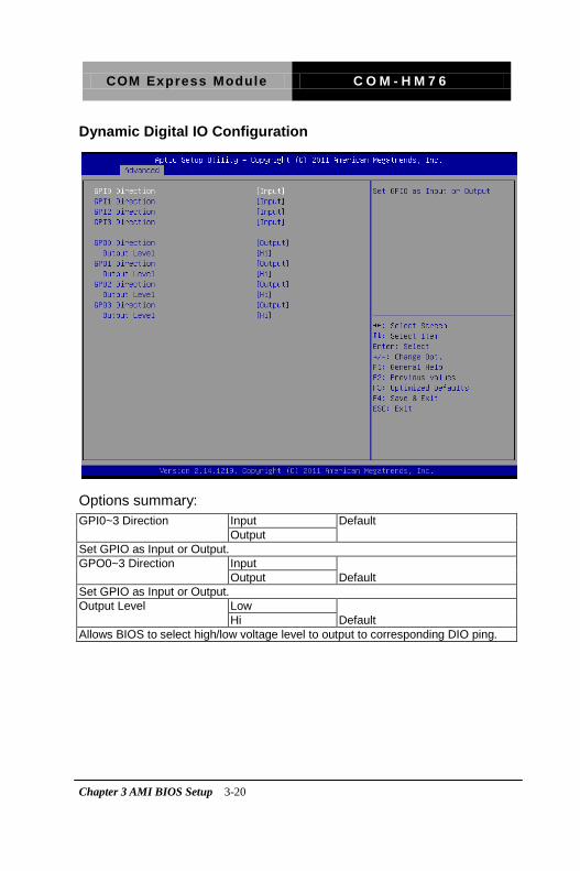
Dynamic Digital IO Configuration
Options summary:
GPI0~3 Direction Input Default
Output
Set GPIO as Input or Output.
GPO0~3 Direction Input
Output Default
Set GPIO as Input or Output.
Output Level Low
Hi Default
Allows BIOS to select high/low voltage level to output to corresponding DIO ping.

COM Express Module C O M - H M 7 6
Chapter 3 AMI BIOS Setup 3-21
Setup submenu: Chipset

COM Express Module C O M - H M 7 6
Chapter 3 AMI BIOS Setup 3-22
PCH-IO Configuration
Option summary:
Power Mode ATX Type Default
AT Type
Select power supply mode
Azalia Disabled
Enabled Default
Control Detection of the Azalia device. Disabled = Azalia will be unconditionally disabled. Enabled = Azalia will be unconditionally Enabled. Auto = Azalia will be enabled if present, disabled other wise.
Azalia Internal HDMI Codec Disabled
Enabled Default
Enable or disable internal HDMI codec for Azalia.
Azalia HDMI codec Port B Disabled Default
Enabled
Enable or disable internal HDMI codec Port for Azalia.
Azalia HDMI codec Port C Disabled
Enabled Default
Enable or disable internal HDMI codec Port for Azalia.

COM Express Module C O M - H M 7 6
Chapter 3 AMI BIOS Setup 3-23
Azalia HDMI codec Port D Disabled Default
Enabled
Enable or disable internal HDMI codec Port for Azalia.
PCH LAN Controller Disabled
Enabled Default
Enable or disable onboard NIC.
Wake on LAN Disabled
Enabled Default
Enable or disable integrated LAN to wake the system. (The Wake On LAN cannot be disabled if ME is on at Sx state)

COM Express Module C O M - H M 7 6
Chapter 3 AMI BIOS Setup 3-24
PCI Express Configuration
Option summary:
PCI Express Root Port (1 - 7)
Enabled Default
Disabled
Control the PCI Express Root Port.
PCI Speed Auto Default
Gen1
Gen2
Select PCI Express port speed.

COM Express Module C O M - H M 7 6
Chapter 3 AMI BIOS Setup 3-25
System Agent (SA) Configuration
Option summary:
PEGO – Gen Speed Auto Default
Gen1
Gen2
Gen3
Configure PEG0 B0:D1:F0 Gen1-Gen3
VT-d Enabled Default
Disabled
Check to enable VT-D function on MCH
COM Express Module C O M - H M 7 6
Chapter 3 AMI BIOS Setup 3-26
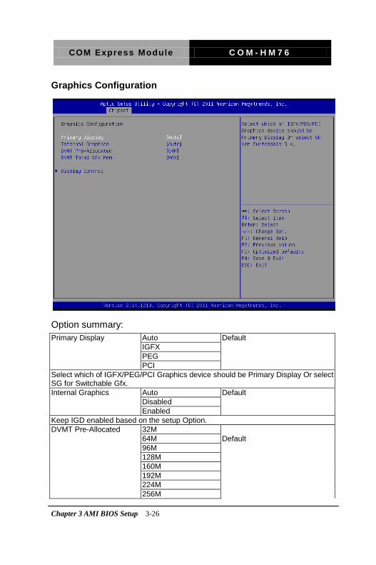
Graphics Configuration
Option summary:
Primary Display Auto Default
IGFX
PEG
PCI
Select which of IGFX/PEG/PCI Graphics device should be Primary Display Or select SG for Switchable Gfx.
Internal Graphics Auto Default
Disabled
Enabled
Keep IGD enabled based on the setup Option.
DVMT Pre-Allocated 32M
64M Default
96M
128M
160M
192M
224M
256M

COM Express Module C O M - H M 7 6
Chapter 3 AMI BIOS Setup 3-27
288M
320M
352M
284M
416M
448M
480M
512M
1024M
Select DVMT 5.0 Pre-Allocated (Fixed) Graphics Memory size used by the Internal Graphics Device.
DVMT Total Gfx Mem 128M
256M
MAX Default
Select DVMT5.0 Total Graphic Memory size used by the Internal Graphics Device.
COM Express Module C O M - H M 7 6
Chapter 3 AMI BIOS Setup 3-28
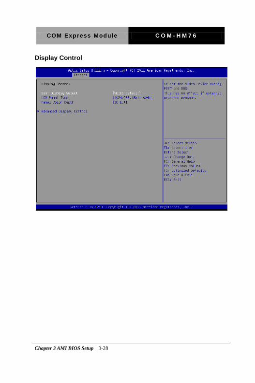
Display Control

COM Express Module C O M - H M 7 6
Chapter 3 AMI BIOS Setup 3-29
Option summary:
Boot Display Select VBIOS Default Default
CRT
HDMI
DVI
LVDS
CRT + LVDS
Select the Video Device which will be activated during POST and DOS. This has no effect if external graphics present.
LCD Panel Type 640x480, 18bit, 60Hz
800x480, 18bit, 60Hz
800x600, 18bit, 60Hz
1024x600, 18bit, 60Hz
1024x768, 18bit, 60Hz Default
1024x768, 24bit, 60Hz
1280x768, 24bit, 60Hz
1280x1024, 48bit, 60Hz
1366x768, 24bit, 60Hz
1440x900, 48bit, 60Hz
1600x1200, 48bit, 60Hz
1920x1080, 48bit, 60Hz
1920x1200, 48bit, 60Hz
Select LCD panel used by internal Graphics Device by selecting the appropriate setup item.
Panel Color Depth 18 Bit Default
24Bit
Select the LFP Panel Color depth

COM Express Module C O M - H M 7 6
Chapter 3 AMI BIOS Setup 3-30
Advanced Display Control

COM Express Module C O M - H M 7 6
Chapter 3 AMI BIOS Setup 3-31
Option summary:
Boot Display Select UEFI boot Default
CRT
EFP
LFP
CRT2
EFP3
EFP2
CRT + LFP
Select the Video Device which will be activated during POST and DOS. This has no effect if external graphics present. UEFI – For UEFI style boot EFP – DVI/HDMI/DP EFP2 – eDP LFP - LVDS
Primary IGFX Boot Display
VBIOS Default Default
CRT
EFP
LFP
CRT2
EFP3
EFP2
LFP2
Select the Video Device which will be activated during POST and DOS. This has no effect if external graphics present. Secondary boot disaply selection will appear based on your selection, VGA modes will be supported only on primary disaply.
Active LFP No LVDS
Int-LVDS Default
SDVO LVDS
eDP Port-D
Select the Active LFP Configuration. No LVDS: VBIOS does not enable LVDS. Int-LVDS: VBIOS enables LVDS driver by Integrated encoder. SDVO LVDS: VBIOS
LCD Panel Type 640x480, 18bit, 60Hz
800x480, 18bit, 60Hz
800x600, 18bit, 60Hz
1024x600, 18bit, 60Hz
1024x768, 18bit, 60Hz Default
1024x768, 24bit, 60Hz
1280x768, 24bit, 60Hz
1280x1024, 48bit, 60Hz
1366x768, 24bit, 60Hz
1440x900, 48bit, 60Hz
COM Express Module C O M - H M 7 6
Chapter 3 AMI BIOS Setup 3-32
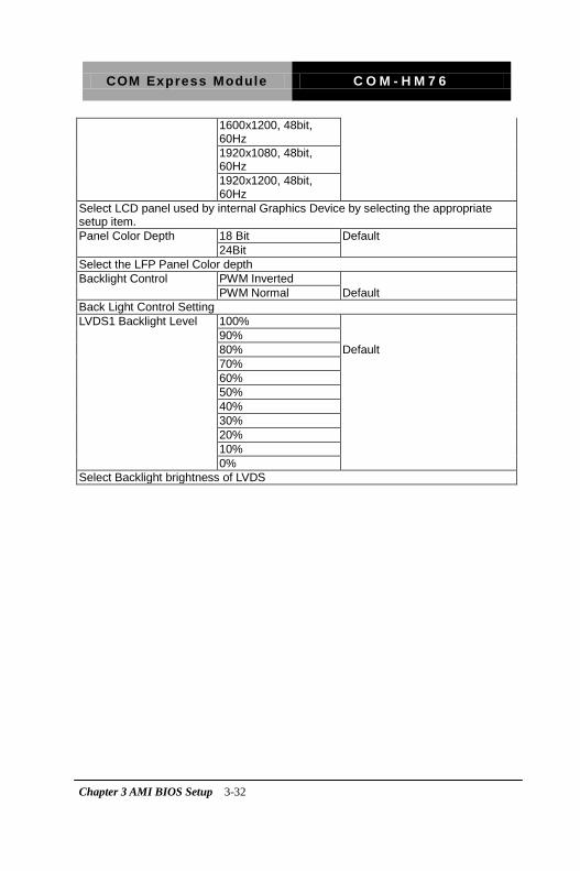
1600x1200, 48bit, 60Hz
1920x1080, 48bit, 60Hz
1920x1200, 48bit, 60Hz
Select LCD panel used by internal Graphics Device by selecting the appropriate setup item.
Panel Color Depth 18 Bit Default
24Bit
Select the LFP Panel Color depth
Backlight Control PWM Inverted
PWM Normal Default
Back Light Control Setting
LVDS1 Backlight Level 100%
90%
80% Default
70%
60%
50%
40%
30%
20%
10%
0%
Select Backlight brightness of LVDS

COM Express Module C O M - H M 7 6
Chapter 3 AMI BIOS Setup 3-33
Setup submenu: Boot
Option summary:
Quiet Boot Disabled
Enabled Default
Enables or Disables showing boot logo.
Launch I82579LM PXE OpROM
Disabled Default
Enabled
En/Disable Legacy boot Option for I82579LM.

COM Express Module C O M - H M 7 6
Chapter 3 AMI BIOS Setup 3-34
BBS Priorities

COM Express Module C O M - H M 7 6
Chapter 3 AMI BIOS Setup 3-35
Security
Change User/Supervisor Password
You can install a Supervisor password, and if you install a supervisor password, you can then install a user password. A user password does not provide access to many of the features in the Setup utility.
If you highlight these items and press Enter, a dialog box appears which lets you enter a password. You can enter no more than six letters or numbers. Press Enter after you have typed in the password. A second dialog box asks you to retype the password for confirmation. Press Enter after you have retyped it correctly. The password is required at boot time, or when the user enters the Setup utility.
Removing the Password
Highlight this item and type in the current password. At the next dialog box press Enter to disable password protection.

COM Express Module C O M - H M 7 6
Chapter 3 AMI BIOS Setup 3-36
Setup submenu: Exit
COM Express Module C O M - H M 7 6
Chapter 4 Driver Installation 4 -1
0BDriver Installation
.
Chapter
4

COM Express Module C O M - H M 7 6
Chapter 4 Driver Installation 4 -2
The COM-HM76 comes with an AutoRun DVD-ROM that contains
all drivers and utilities that can help you to install the driver
automatically.
Insert the driver DVD, the driver DVD-title will auto start and show
the installation guide. If not, please follow the sequence below to
install the drivers.
Follow the sequence below to install the drivers:
Step 1 – Install Chipset Driver
Step 2 – Install VGA Driver
Step 3 – Install LAN Driver
Step 4 – Install Audio Driver
Step 5 – Install USB3.0 Driver
Step 6 – Install RAID & AHCI Driver
Step 7 – Install ME Driver
Please read instructions below for further detailed installations.

COM Express Module C O M - H M 7 6
Chapter 4 Driver Installation 4 -3
4.1 Installation:
Insert the COM-HM76 DVD-ROM into the DVD-ROM drive. And
install the drivers from Step 1 to Step 7 in order.
Step 1 – Install Chipset Driver
1. Click on the Step 1 - Chipset folder and double click on the Setup.exe file
2. Follow the instructions that the window shows
3. The system will help you install the driver automatically
Step 2 – Install VGA Driver
1. Click on the Step 2 - Graphics folder and select the OS folder your system is
2. Double click on the Setup.exe file located in each OS folder
3. Follow the instructions that the window shows
4. The system will help you install the driver automatically
Step 3 –Install LAN Driver
1. Click on the Step 3 - LAN folder and select the OS folder your system is and double click on the .exe file located in each OS folder
2. Follow the instructions that the window shows
3. The system will help you install the driver automatically

COM Express Module C O M - H M 7 6
Chapter 4 Driver Installation 4 -4
Step 4 –Install Audio Driver
1. Click on the Step 4 - Audio folder and select the Win7_Win8 folder
2. Double click on the Setup.exe file
3. Follow the instructions that the window shows
4. The system will help you install the driver automatically
Step 5 – Install USB3.0 Driver
1. Click on the Step 5 - USB3.0 folder and double click on the Setup.exe file
2. Follow the instructions that the window shows
3. The system will help you install the driver automatically
Step 6 – Install RAID & AHCI Driver
Please refer to the Appendix C AHCI Setting
Step 7 – Install ME Driver
1. Click on the Step 7 - ME folder and double click on the Setup.exe file
2. Follow the instructions that the window shows
3. The system will help you install the driver automatically

COM Express Module C O M - H M 7 6
Appendix A Programming the Watchdog Timer A-1
Programming the
Watchdog Timer
Appendix
A

COM Express Module C O M - H M 7 6
Appendix A Programming the Watchdog Timer A-2
A.1 Watchdog Timer Initial Program
Table 1 : Embedded BRAM relative register table
Default Value Note
Index 0x284(Note1) BRAM Index Register
Data 0x285(Note2) BRAM Data Register
Logical Device Number 0xA8(Note3) Watch dog Logical Device Number
Function and Device Number 0x00(Note4) Watch dog Function/Device Number
Table 2 : Watchdog relative register table
Option
Register
BitNum Value Note
Timer Counter 0x00(Note5) (Note10)
Time of watchdog
timer
(0~255)
Counting Unit 0x01(Note6) 0(Note7) 0(Note11)
Select time unit.
0: second
1: minute
Watchdog RST pulse
width 0x01(Note8) [3:2](Note9) 0(Note12)
0: 20ms
1: 60ms
2: 100ms
3: 250ms

COM Express Module C O M - H M 7 6
Appendix A Programming the Watchdog Timer A-3
************************************************************************************
// Embedded BRAM relative definition (Please reference to Table 1)
#define byte EcBRAMIndex //This parameter is represented from Note1
#define byte EcBRAMData //This parameter is represented from Note2
#define byte BRAMLDNReg //This parameter is represented from Note3
#define byte BRAMFnDataReg //This parameter is represented from Note4
#define void EcBRAMWriteByte(byte Offset, byte Value);
#define byte EcBRAMReadByte(byte Offset);
#define void IOWriteByte(byte Offset, byte Value);
#define byte IOReadByte(byte Offset);
// Watch Dog relative definition (Please reference to Table 2)
#define byte TimerReg //This parameter is represented from Note5
#define byte TimerVal // This parameter is represented from Note10
#define byte UnitReg //This parameter is represented from Note6
#define byte UnitBit //This parameter is represented from Note7
#define byte UnitVal //This parameter is represented from Note11
#define byte RSTReg //This parameter is represented from Note8
#define byte RSTBit //This parameter is represented from Note9
#define byte RSTVal //This parameter is represented from Note12
************************************************************************************

COM Express Module C O M - H M 7 6
Appendix A Programming the Watchdog Timer A-4
************************************************************************************
VOID Main(){
// Procedure : AaeonWDTConfig
// (byte)Timer : Time of WDT timer.(0x00~0xFF)
// (boolean)Unit : Select time unit(0: second, 1: minute).
AaeonWDTConfig();
// Procedure : AaeonWDTEnable
// This procudure will enable the WDT counting.
AaeonWDTEnable();
}
************************************************************************************

COM Express Module C O M - H M 7 6
Appendix A Programming the Watchdog Timer A-5
************************************************************************************
// Procedure : AaeonWDTEnable
VOID AaeonWDTEnable (){
WDTEnableDisable(1);
}
// Procedure : AaeonWDTConfig
VOID AaeonWDTConfig (){
// Disable WDT counting
WDTEnableDisable(0);
// WDT relative parameter setting
WDTParameterSetting();
}
VOID WDTEnableDisable(byte Value){
ECBRAMWriteByte(TimerReg , Value);
}
VOID WDTParameterSetting(){
Byte TempByte;
// Watchdog Timer counter setting
ECBRAMWriteByte(TimerReg , TimerVal);
// WDT counting unit setting
TempByte = ECBRAMReadByte(UnitReg);
TempByte |= (UnitVal << UnitBit);
ECBRAMWriteByte(UnitReg , TempByte);
// WDT RST pulse width setting
TempByte = ECBRAMReadByte(RSTReg);
TempByte |= (RSTVal << RSTBit);
ECBRAMWriteByte(RSTReg , TempByte);
}
************************************************************************************

COM Express Module C O M - H M 7 6
Appendix A Programming the Watchdog Timer A-6
************************************************************************************
VOID ECBRAMWriteByte(byte OPReg, byte OPBit, byte Value){
IOWriteByte(EcBRAMIndex, 0x10);
IOWriteByte(EcBRAMData, BRAMLDNReg);
IOWriteByte(EcBRAMIndex, 0x11);
IOWriteByte(EcBRAMData, BRAMFnDataReg);
IOWriteByte(EcBRAMIndex, 0x13 + OPReg);
IOWriteByte(EcBRAMData, Value);
IOWriteByte(EcBRAMIndex, 0x12);
IOWriteByte(EcBRAMData, 0x30); //Write start
}
Byte ECBRAMReadByte(byte OPReg){
IOWriteByte(EcBRAMIndex, 0x10);
IOWriteByte(EcBRAMData, BRAMLDNReg);
IOWriteByte(EcBRAMIndex, 0x11);
IOWriteByte(EcBRAMData, BRAMFnDataReg);
IOWriteByte(EcBRAMIndex, 0x12);
IOWriteByte(EcBRAMData, 0x10); //Read start
IOWriteByte(EcBRAMIndex, 0x13 + OPReg);
Return IOReadByte(EcBRAMData, Value);
}
************************************************************************************

COM Express Module C O M - H M 7 6
Appendix B I/O Information B - 1
I/O Information
Appendix
B

COM Express Module C O M - H M 7 6
Appendix B I/O Information B - 2
B.1 I/O Address Map

COM Express Module C O M - H M 7 6
Appendix B I/O Information B - 3
COM Express Module C O M - H M 7 6
Appendix B I/O Information B - 4
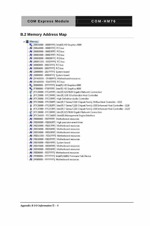
B.2 Memory Address Map

COM Express Module C O M - H M 7 6
Appendix B I/O Information B - 5
B.3 IRQ Mapping Chart

COM Express Module C O M - H M 7 6
Appendix B I/O Information B - 6

COM Express Module C O M - H M 7 6
Appendix B I/O Information B - 7
B.4 DMA Channel Assignments

COM Express Module C O M - H M 7 6
Appendix C RAID & AHCI Settings C-1
AHCI Setting
Appendix
C

COM Express Module C O M - H M 7 6
Appendix C RAID & AHCI Settings C-2
C.1 Setting AHCI
OS installation to setup AHCI Mode
Step 1: Copy the files below from “Driver CD ->Step 6 - RAID&AHCI” to Disk
Step 2: Connect the USB Floppy (disk with AHCI files) to the board

COM Express Module C O M - H M 7 6
Appendix C RAID & AHCI Settings C-3
Step 3: The setting procedures “ In BIOS Setup Menu” A: Advanced -> SATA Configuration -> SATA Configuration -> SATA Mode -> AHCI Mode
Step 4: The setting procedures “In BIOS Setup Menu” B: Boot -> Boot Option #1 -> DVD-ROM Type

COM Express Module C O M - H M 7 6
Appendix C RAID & AHCI Settings C-4
Step 5: The setting procedures “In BIOS Setup Menu” C: Save & Exit -> Save Changes and Exit
Step 6: Setup OS

COM Express Module C O M - H M 7 6
Appendix C RAID & AHCI Settings C-5
Step 7: Press “F6”
Step 8: Choose “S”
COM Express Module C O M - H M 7 6
Appendix C RAID & AHCI Settings C-6
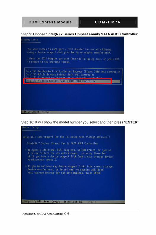
Step 9: Choose “Intel(R) 7 Series Chipset Family SATA AHCI Controller”
Step 10: It will show the model number you select and then press “ENTER”
COM Express Module C O M - H M 7 6
Appendix C RAID & AHCI Settings C-7
Step 11: Setup is loading files