comparative structure cost of modern commercial buildings
TRANSCRIPT

Comparative Structure Cost ofModern Commercial Buildings
(Second Edition)
Cost and Value

The Steel Construction Institute develops and promotes the effective use of steel in construction. It is an independent, membership based organisation.
SCI's research and development activities cover many aspects of steel construction including multi-storey construction, industrial buildings, bridges, civil engineering and offshore engineering. Forms of construction addressed include steel and composite frames, light steel framing systems and modular construction. Activities encompass guidance on structural design in carbon and stainless steels, dynamic performance, fire engineering, sustainable construction, architectural design, building physics (including design for acoustic and thermal performance), value engineering, and information technology.
Membership is open to all organisations and individuals that are concerned with the use of steel in construction. Members include designers, contractors, suppliers, steelwork contractors, academics and government departments in the United Kingdom, elsewhere in Europe and in countries around the world. The SCI’s income is derived from subscriptions from its members, revenue from research contracts and consultancy services, publication sales and course fees.
The benefits of corporate membership include access to an independent specialist advisory service, free issue of SCI publications as soon as they are produced and free access to Steelbiz, an online technical information system. A Membership Information Pack is available on request from the Membership Manager.
The Steel Construction Institute, Silwood Park, Ascot, Berkshire, SL5 7QN. Telephone: +44 (0) 1344 623345 Fax: +44 (0) 1344 622944 Email: [email protected] For information on publications, telephone direct: +44 (0) 1344 872775 or Email: [email protected] For information on courses, telephone direct: +44 (0) 1344 872776 or Email: [email protected] World Wide Web site: http://www.steel-sci.org Visit www.steelbiz.org – the 24×7 online technical information system for steel design and construction Cover photo: Mid City Place, High Holbon, London. The 300,000 sq ft office/retail development was designed and fast-track constructed in just 15 months. It comprises a long span steel frame and composite floors.
Client: Matsushita Investment and Development Co.
Architect: Kohn Pedersen Fox Associates
Structural and services engineer: Waterman Partnership
Construction Manager: Bovis Lend Lease
The Steel Construction Institute

SCI PUBLICATION P137
Comparative Structure Cost of
Modern Commercial Buildings
(Second Edition)
S J Hicks BEng PhD (Cantab)
R M Lawson BSc (Eng) PhD ACGI CEng MICE MIStructE
J W Rackham BSc (Eng) MSc DIC PhD CEng MICE
P Fordham BSc MRICS
Published by: The Steel Construction Institute Silwood Park Ascot Berkshire SL5 7QN Tel: 01344 623345 Fax: 01344 622944

P137v02d10.doc ii Printed 08/11/04
2004 The Steel Construction Institute
Apart from any fair dealing for the purposes of research or private study or criticism or review, as permitted under theCopyright Designs and Patents Act, 1988, this publication may not be reproduced, stored or transmitted, in any form or byany means, without the prior permission in writing of the publishers, or in the case of reprographic reproduction only inaccordance with the terms of the licences issued by the UK Copyright Licensing Agency, or in accordance with the termsof licences issued by the appropriate Reproduction Rights Organisation outside the UK.
Enquiries concerning reproduction outside the terms stated here should be sent to the publishers, The Steel ConstructionInstitute, at the address given on the title page.
Although care has been taken to ensure, to the best of our knowledge, that all data and information contained herein areaccurate to the extent that they relate to either matters of fact or accepted practice or matters of opinion at the time ofpublication, The Steel Construction Institute, the authors and the reviewers assume no responsibility for any errors in ormisinterpretations of such data and/or information or any loss or damage arising from or related to their use.
Publications supplied to the Members of the Institute at a discount are not for resale by them.
Publication Number: SCI P137
ISBN 1 85942 157 1
British Library Cataloguing-in-Publication Data.
A catalogue record for this book is available from the British Library.
P137v02d10.doc iii Printed 08/11/04
FOREWORD
The first edition of this publication presented a summary of a study carried out in 1992/93 to compare the cost differences between different structural building forms. Since then, construction technologies and the costs of construction activities have changed and it is now timely to update the original study. A new study was carried out in 2003/2004, and this publication presents the results of that study. It was prepared by Stephen Hicks, Mark Lawson and Jim Rackham of The Steel Construction Institute (SCI) and Peter Fordham of Davis Langdon LLP.
In addition to the authors, acknowledgement is made to the following individuals and organisations who were involved in the work and contributed to this publication:
Mr S Rawlinson Davis Langdon LLP Mr D Holmes Davis Langdon LLP Mr R Chaman MACE Ltd Mr J Trask MACE Ltd Mr M White Arup Mr M Webb Corus Construction and Industrial Mr C Smart Corus Construction and Industrial Dr S Popo-Ola Imperial College, London Notable new inclusions in the study are the Slimdek® system (Slimdek is a registered trademark of Corus), new cellular and fabricated beam designs using fire protective coatings, and a new post-tensioned ribbed slab scheme. The construction programmes for the steel and concrete schemes have been updated to take account of modern practice.
The design of the steel schemes was carried out by the SCI. The design of the concrete schemes, and the design of the foundations for all the schemes, was carried out by Arup.
Construction programmes for all the schemes were prepared by MACE Ltd and the costs were produced by Davis Langdon LLP. The costs of all schemes are updated to reflect construction prices at the end of the 2003 calendar year.
The work was funded by Corus Construction and Industrial and a brochure presenting the key results of the study has been published by Corus entitled: Supporting the Commercial Decision.
Since the conclusion to the study at the beginning of 2004, prices in the construction industry have been subject to change. Some of the options reported in the publication have been updated to August 2004 prices, and the changes are reviewed in Appendix B.

P137v02d10.doc iv Printed 08/11/04

P137v02d10.doc v Printed 08/11/04
Contents Page No.
1 INTRODUCTION 1 1.1 Methodology of the study 2 1.2 Comment on changes since 1993 3
2 STRUCTURAL FORMS CONSIDERED IN THE STUDY 6 2.1 Short-span systems (up to 7.5 m) 7 2.2 Long-span systems (12 m and above) 9
3 BUILDING FORMS USED IN THE STUDY 14 3.1 Architectural features 14 3.2 Structural design requirements and criteria 18 3.3 Non-structural design requirements 19
4 STRUCTURAL SCHEMES ADOPTED IN THE STUDY 22 4.1 Short-span schemes 22 4.2 Long-span schemes 24 4.3 Accommodation of services in the floor zone 25
5 PLANS, CROSS-SECTIONS AND SUMMARY OF STRUCTURAL SCHEMES DEVELOPED IN THE STUDY 29 5.1 Building A 29 5.2 Building B 29 5.3 Summary of the designs 29
6 DESIGN OF NON-FRAME COMPONENTS 51 6.1 Fire protection 51 6.2 Cladding 52 6.3 Foundations 52 6.4 Mechanical services 54 6.5 Other common items 54
7 CONSTRUCTION PROGRAMMING 55 7.1 Common assumptions 55 7.2 Additional assumptions for Building A 55 7.3 Additional assumptions for Building B 55 7.4 Construction rates 56 7.5 Construction programmes – Building A 56 7.6 Construction programmes – Building B 57
8 BUILDING COSTS 58 8.1 Introduction 58 8.2 General basis of pricing 58 8.3 Market conditions 59 8.4 Regional variations 59 8.5 Preliminaries 60 8.6 Time-related savings 60 8.7 Steel construction 61 8.8 Concrete construction 62 8.9 Other elements 64 8.10 Elemental breakdown of costs 64 8.11 Comparison of building costs 64

P137v02d10.doc vi Printed 08/11/04
9 CONCLUSIONS 71
10 REFERENCES 73
APPENDIX A DETAILED CONSTRUCTION PROGRAMMES 77 A.1 Construction programme summaries 77 A.2 Detailed construction programmes 80
APPENDIX B REVIEW AT AUGUST 2004 85

P137v02d10.doc vii Printed 08/11/04
SUMMARY
This publication presents the results of a cost comparative study to fourth quarter 2003 prices, for a range of modern structural options for commercial buildings, which updates the previous cost study of 1993.
Two buildings, typical of modern commercial building construction, are fully designed for a range of steel, composite and concrete options. The cost study includes the major variable items of structure, foundations, cladding and services. Account has also been taken of time-related savings in determining the net building costs.
It is shown that the cost variation in the most appropriate steel options is relatively small when considered globally in terms of building cost rather than pure structural cost. The steel and composite options proved to be more economic than the reinforced concrete options, particularly when the additional time-related savings were taken into account. The cost premium for long span steel construction is negligible for the heavily serviced building (Building B).
It is concluded that most modern structural systems in steel and composite construction have broad economic merit. However, it is necessary to consider the choice of the structural system in relation to the influence on other non-structural, and often more expensive, aspects of the building construction. The conclusions of the study probably apply equally to a wider range of building forms; for example, hospitals, educational and retail buildings.

P137v02d10.doc viii Printed 08/11/04

P137v02d10.doc 1 Printed 08/11/04
1 INTRODUCTION
There have been significant developments in the design of commercial and other multi-storey buildings in recent years, and many new structural systems have gained wide acceptance. The developments have occurred in the context of an increasing market share (now over 70%) for steel multi-storey frames in the UK commercial sector.
The motivation for these improvements in the design and construction of modern buildings has come from changing clients’ requirements for the procurement, use, quality and adaptability of their buildings. The Egan Report, Re-thinking Construction[1], has also called for a radical re-examination of construction processes to encourage off-site manufacture, to improve quality and speed on site, which has led to a greater innovation in steel solutions, and this is reflected in the schemes developed in this study.
The issue of the comparative cost among a range of steel and concrete options was first addressed in a comprehensive study in 1993[2]. The publication resulting from that study provided information on popular and readily available structural systems at that time. The systems included slim floor construction, composite beams, various long-span systems, and regular forms of concrete construction.
This publication presents the results of a new study carried out in 2003/2004. It provides information on new structural systems in steel, concrete and composite construction, and reviews the cost and construction programmes of all the construction systems, leading to updated costs and conclusions. Both short-span (6 to 7.5 m) and long-span (12 to 15 m) systems are included.
The publication covers the influence of the choice of structural system on the non-frame elements such as foundations, cladding and services, which can have a major effect on overall costs. Speed of construction is generally accepted as being one of the major benefits of steel framed buildings, and is included in the broader economic assessment.
In order to carry out a representative appraisal of these systems over a range of applications, two generic buildings were identified, as in the 1993 study: one being a developer’s standard specification; the other a large prestige building. The first building is located hypothetically in Manchester, and the second in central London (this is a change from the 1993 study, in which both buildings were located in outer London).
A critical factor in examining the relative cost of the structural systems is the degree of horizontal servicing (air-conditioning) required in the two buildings. In general, the short-span systems accommodate services below the structure, whereas most of the long-span systems are designed to accommodate service zones within the structural depth. Recent design guidance[3] [4] addresses service integration in steel framed buildings.
This new study included the Slimdek® system, which uses Asymmetric Slimflor® Beams (ASBs) as its primary structural members, and either Rectangular Hollow Section Slimflor® Fabricated Beams (RHSFBs) or conventional downstand beams as edge beams. Design guidance on the Slimdek® system is

P137v02d10.doc 2 Printed 08/11/04
presented in two SCI publications[5] [6]. The Slimdek® designs replace the slim floor designs, which used Slimflor® fabricated beams (SFBs) and deep decking in the previous publication.
Long-span systems, based on the cellular beam concept, have also achieved high market acceptance. New technologies included in this study are fabricated cellular beams and off-site fire protection by intumescent coatings.
Section 5 summarises the structural designs of all the systems considered for the two buildings. The information is presented in the form of tabular data, plan arrangements and typical sections. Costs are based on representative current rates for the quantified elements.
1.1 Methodology of the study For each of the two generic buildings, a range of structural options was considered. Each option is representative of modern construction techniques that may be employed for commercial buildings, although some options may be considered to be more widely used than others.
The design of the steel/composite options was carried out by The Steel Construction Institute in accordance with BS 5950-1:2000[7] and BS 5950-3:1990[8], using software and design tables. The frames were designed for normal office loading and were braced against wind loads. Robustness was checked in the light of the new requirements of the Building Regulations[9] (which came into effect in 2004). Deflection limits were taken as appropriate for buildings of this type. However, deflection limits for the highly glazed
Figure 1.1 Long-span steel construction used at Mid City Place,
London

P137v02d10.doc 3 Printed 08/11/04
façades were made stricter than in the 1993 study. These design criteria are discussed in Section 3.2.
The quantities of steel sections, fire protection, concrete, steel decking, etc. were determined for the two generic buildings. An additional cost allowance of 7.5% equivalent weight of steel was made for all connections, except for the Slimflor® and Slimdek® schemes, where an allowance of 10% was made to reflect their greater complexity.
The design of the concrete options and the foundations for all designs were carried out by Arup. (The designs have been revised slightly since the 1993 edition of this publication.) These designs are in accordance with BS 8110-1:1997[10] for conventional reinforced concrete. Manufacturers’ data was also used for the precast floor units in the concrete designs.
The construction programming information was provided by MACE Limited. Many of the programming aspects are common to the structural options in each building, and the study concentrates on the differences in the speed of construction. A single tower crane was used in Building A and two in Building B. (The craneage influences the rate at which elements could be lifted, and so the speed of construction.) Changes in construction practice, particularly the modern safety requirements and speed of re-usable fromwork for concrete construction, were recognised in the study.
The building cost data was provided by Davis Langdon LLP, based on information obtained from a range of sources and concentrating on ‘actual’ prices on recent competitively tendered projects (to the last quarter of 2003).
The cladding design and ‘quality’ was also important in cases where the building height was affected by the construction depth. Representative cost rates were selected, depending on the form of cladding used in the two buildings. Estimates were also made of the cost of the stairways, cladding supports and other finishes which, although common to all the designs, affect the overall cost of the construction.
In Building B, the core positions and horizontal service layout were also addressed, as these aspects have an effect on the ease of integration of structure and services for the various options.
1.2 Comment on changes since 1993 Certain simplifying assumptions have had to be made in order to avoid the inevitable complexity that exists in the design of ‘real’ buildings. The forms of the buildings are representative and are selected to draw out the important differences among the structural systems. The building forms are unchanged since the 1993 study, in order to facilitate examination of trends in the cost of the structural systems. However, a number of changes were considered appropriate since the 1993 study to reflect modern design practice and office building specification. These changes are set out in Table 1.2.
The following points should be noted when considering the information presented in this publication:
1. The study is based on the most efficient design of the structural options for the two building forms considered. New structural systems, such as

P137v02d10.doc 4 Printed 08/11/04
Slimdek® and fabricated beams, are now included, as they have proved to be popular in recent years.
2. Inevitably, the regular form of the buildings means that they may be less complex and less costly in materials use than ‘real’ buildings. Nevertheless, the comparison is valid.
3. Tender prices in the UK have increased steadily since the 1993 edition of this publication. The total build cost in 2003 is now 65% higher for Building A and 85% higher for Building B than in 1993.
4. The current study uses site management costs (preliminaries) of approximately 13% and 15% for Buildings A and B respectively; both these percentages have increased significantly since 1993.
5. Wherever possible, the tender prices used in the study have been extracted from projects that have been competitively tendered in late 2003. The price levels reflect those in Manchester for Building A, and central London for Building B (rather than outer London in the 1993 study).
6. In modern value engineering, account may also be taken of the non-quantified benefits and the increased ‘value’ of the building in terms of:
• Increased column-free space of the long-span systems, which gives greater flexibility in freedom of use.
• Planning requirements, which may limit overall building height, and encourage the use of Slimdek® or other shallow floor systems.
• Ease of future adaptation and change of use, including re-servicing.
• Greater lettable area with smaller-sized columns, or no internal columns.
• Less disruption during the construction process by just-in-time delivery to site, and by a shorter construction period (this is particularly important for inner-city sites).
• Operational energy savings, which may be enhanced by thermal capacity or other active measures.
These aspects are often included in modern ‘value engineering’ assessments, but no direct financial account is taken of these issues in this study.
A further assessment of cost changes to August 2004 is made in Appendix B.
P137v02d10.doc 5 Printed 08/11/04
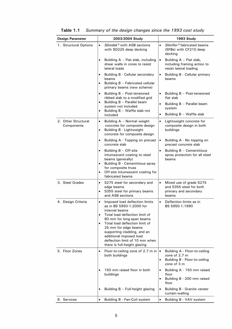
Table 1.1 Summary of the design changes since the 1993 cost study
Design Parameter 2003/2004 Study 1993 Study
• Slimdek® with ASB sections with SD225 deep decking
• Slimflor® fabricated beams (SFBs) with CF210 deep decking
• Building A – Flat slab, including shear walls in cores to resist lateral loads
• Building A – Flat slab, including framing action to resist lateral loading
• Building B - Cellular secondary beams
• Building B – Fabricated cellular primary beams (new scheme)
• Building B - Cellular primary beams
• Building B – Post-tensioned flat slab
• Building B – Parallel beam system
1. Structural Options
• Building B – Post-tensioned ribbed slab to a modified grid
• Building B – Parallel beam system not included
• Building B – Waffle slab not included • Building B – Waffle slab
• Building A – Normal weight concrete for composite design • Building B - Lightweight concrete for composite design
• Lightweight concrete for composite design in both buildings
• Building A - Topping on precast concrete slab
• Building A - No topping on precast concrete slab
2. Other Structural Components
• Building B – Off-site intumescent coating to steel beams (generally)
• Building B - Cementitious spray for composite truss
• Off-site intumescent coating for fabricated beams
• Building B – Cementitious spray protection for all steel beams
3. Steel Grades • S275 steel for secondary and edge beams
• S355 steel for primary beams and ASB sections
• Mixed use of grade S275 and S355 steel for both primary and secondary beams
• Deflection limits as in BS 5950-1:1990
4. Design Criteria • Imposed load deflection limits as in BS 5950-1:2000 for internal beams
• Total load deflection limit of 60 mm for long-span beams
• Total load deflection limit of 25 mm for edge beams supporting cladding, and an additional imposed load deflection limit of 10 mm when there is full-height glazing
• Floor-to-ceiling zone of 2.7 m in both buildings
• Building A - Floor-to-ceiling zone of 2.7 m
• Building B - Floor-to-ceiling zone of 3 m
• 150 mm raised floor in both buildings
• Building A - 150 mm raised floor
• Building B - 200 mm raised floor
5. Floor Zones
• Building B – Full-height glazing • Building B - Granite veneer curtain-walling
6. Services • Building B - Fan-Coil system • Building B - VAV system

P137v02d10.doc 6 Printed 08/11/04
2 STRUCTURAL FORMS CONSIDERED IN THE STUDY
The following sections review the various structural forms considered in the study. Schemes developed using the most appropriate forms for the buildings defined in the study are presented later in Section 4.
The structural forms that were considered may be expressed in two categories: short-span and long-span. For the purposes of the publication, short-span is defined as spans up to 7.5 m, and long-span as spans of 12 m and above. Typical span capabilities of the forms considered are presented in Table 2.1. Many of the structural steel forms are described in detail in a recent SCI publication[11].
Table 2.1 Summary of typical spans of structural forms (presented in increasing span capabilities)
Short span Long span
Span (m) 6 8 10 12 14 18
R.C. flat slab
Slimdek with deep composite slab
Post-tensioned concrete ribbed slab
Composite beam and slab
R.C. beam and slab
Slimflor beams with p.c. concrete slabs
Stub girder
Prestressed concrete T beams
Tapered girder
Composite beam with web openings
Cellular composite beam
Haunched composite beam
Composite truss
Precast concrete hollow core slabs
4 16
R.C. waffle slabs
Parallel beam system
P137v02d10.doc 7 Printed 08/11/04
2.1 Short-span systems (up to 7.5 m) Short-span systems considered in the study were:
• Slimflor® beams with pre-cast concrete slabs.
• Asymmetric Slimflor® Beams (ASBs) with deep composite slabs (Slimdek®).
• Composite beams and composite slabs.
• Reinforced concrete flat slabs.
• RC waffle slabs.
2.1.1 Slimflor® beams with precast concrete slabs In this conventional application of slim floor beams, hollow core precast concrete slabs and Slimflor® fabricated beams occupy the same depth, which produces a shallow floor system, and avoids the use of downstand beams[12]. It results in a flat soffit, below which offers an uninterrupted space for accommodating and attaching services. A steel plate is welded to the bottom flange of a UC section to provide the support to the slab, and an in-situ concrete is poured around the UC section. No fire protection is required for up to 60 minutes resistance because of the partial encasement of the steel section, but protection can be applied to the bottom flange plate to provide enhanced fire resistance.
The hollow core precast units should be designed to take account of the non-rigid support conditions (i.e. the curvature of the supporting beam), which affects the transverse shear resistance of the p.c. units at the supports. The shear transfer can be improved by an in-situ topping, or by bar reinforcement passing over or through the beams and embedded in the filled hollow cores. This also improves the fire resistance of the p.c. units.
In all buildings, additional provision for robustness is now required, for which tie reinforcement placed between the precast units is effective. Robustness is also enhanced by the reinforcement in the concrete topping, which ensures the floor plate acts like a diaphragm. This ‘diaphragm action’ is sufficient to transfer wind loads to the braced cores, but some form of shear connection between the slab and edge beams is also required. Guidance is given in a SCI publication[13].
Where downstand edge beams are not possible for architectural reasons, RHS Slimflor® beams[6] may be considered. These edge beams comprise a Rolled Hollow Section (RHS) and a ‘flange plate’ welded to the underside. This RHS section preserves the flat construction at the edge of the building and offers a steel ‘face’ on the perimeter to which cladding attachments can be made readily.
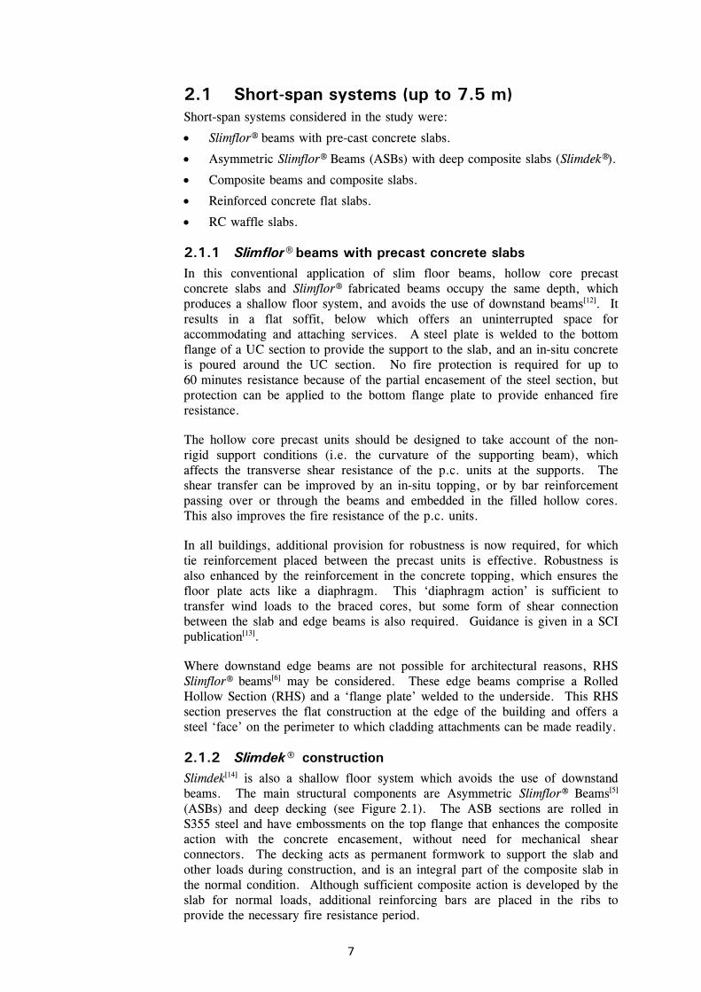
2.1.2 Slimdek® construction Slimdek[14] is also a shallow floor system which avoids the use of downstand beams. The main structural components are Asymmetric Slimflor® Beams[5] (ASBs) and deep decking (see Figure 2.1). The ASB sections are rolled in S355 steel and have embossments on the top flange that enhances the composite action with the concrete encasement, without need for mechanical shear connectors. The decking acts as permanent formwork to support the slab and other loads during construction, and is an integral part of the composite slab in the normal condition. Although sufficient composite action is developed by the slab for normal loads, additional reinforcing bars are placed in the ribs to provide the necessary fire resistance period.

P137v02d10.doc 8 Printed 08/11/04
This form of construction has been developed specifically for spans between 6 and 9 m, and can be more economic than conventional Slimflor® beams. An extended range of ASB sections is now available. New thinner web ASB sections are designed to be fire protected on their exposed bottom flange. Edge beams may be RHS Slimflor® beams, to preserve a flat soffit, or downstand beams when permitted by the architectural design of the façade.
The deep decking, known as SD 225, is 225 mm deep and 1.25 mm thick in S350 steel, which provides a ribbed soffit to the slab. (It replaces the former CF210 decking used in the 1993 study.) Small diameter service pipes may be located between the ribs, passing through the web of the beams where necessary. The slab depth is controlled either by the minimum concrete depth over the steel decking, for fire resistance purposes, or by the minimum concrete depth above the steel beam over which a nominal mesh is placed. In practice, a typical slab depth of 300 mm is used with 75 mm cover to the decking. Decking spans of up to 6 m can usually be achieved without need for propping, which may be extended to 9 m when the slab is propped during construction until it has gained sufficient strength.
2.1.3 Composite beams and slabs Composite beams and slabs with steel decking and in-situ concrete are widely used in steel construction. Composite beams[15] [16] are steel beams designed to act compositely with an in-situ floor slab by the use of welded shear connectors. This action greatly increases the strength and stiffness of the steel beams. Steel decking is used to act as permanent formwork and as ‘reinforcement’ to the slab. Decking is an integral part of all the ‘composite’ systems and its design largely depends on the spacing of the beams and the depth of the slab.
Figure 2.1 ASB sections and deep decking

P137v02d10.doc 9 Printed 08/11/04
A new range or deck profiles has been developed with depths of 50 to 80 mm, which have improved bending and composite properties. Slab spans of 3 to 4 m are most common, with decking thicknesses of between 0.9 mm and 1.2 mm, leading to typical slab depths of 130 to 150 mm. Mesh reinforcement is placed in the slab to enhance its fire resistance, to act as transverse reinforcement and to minimise cracking. The mesh size depends on the fire resistance requirement and whether or not the slab is propped. Lightweight concrete is often used for composite construction in the UK, but it is not available in all regions.
2.1.4 Reinforced concrete flat slabs Reinforced concrete flat slabs are used commonly for spans up to 9 m, and are particularly suited to square grids. For longer spans, the slabs are often post-tensioned and incorporate a fabricated shear head to maintain the flat soffit. The flat soffit makes the formwork simple and the use of removable table forms can result in a fast construction sequence. It also gives maximum flexibility for services distribution within the ceiling void. Flat slabs are less flexible if large holes are required, especially near to a column, and are difficult to modify after construction.
2.1.5 Reinforced concrete waffle slabs In the past, waffle slab construction was popular for buildings with large column grids. It can be economic because the self-weight of the slab is reduced by provision of void forms in the soffit to create a waffle appearance. This form of construction is often used where the soffit is exposed. Typically, a 400 mm deep slab is required for a 7.5 m square grid, and the slab depth over the thinnest part is 100 mm for fire resistance and for local load requirements. The amount of reinforcement is determined by assuming that the slab is supported on orthogonal beam strips. Because of the deeper and lighter slab, the weight of reinforcement may be reduced relative to the flat slab option. The void formers are omitted near the columns to improve the shear transfer to the columns.
This concrete option is relatively inefficient over the spans relevant for this study and is more economic for spans of the order of 8 to 10 m. It was therefore not considered further.
2.2 Long-span systems (12 m and above) Long-span systems considered in the study were:
• Cellular composite beams.
• Composite beams with web openings.
• Tapered fabricated girders.
• Haunched composite beams.
• Composite trusses.
• Parallel beam system.
• Stub-girders.
• Post-tensioned concrete ribbed slabs.
• Precast concrete solutions.

P137v02d10.doc 10 Printed 08/11/04
2.2.1 Cellular beams Cellular beams may be fabricated with regular openings by modern techniques of automatic cutting and re-welding of hot rolled steel sections, or by direct fabrication from plates. They have become very popular in long-span construction because of their efficient creation of regular openings for circular ducting, as in the example of Figure 2.2.
Perforated beams made from hot rolled sections can have hexagonal openings (as in castellated beams), elongated openings or circular openings (as in modern cellular beams)[16]. The range of size and spacing of the regular openings is limited by the cutting and re-welding process. The openings may be filled-in close to the supports, or at location of point loads, where there are higher shear loads. Elongated openings can be provided in the beam in low shear regions. Beams can be made from different sizes of top and bottom chords (Tees) in order to gain maximum efficiency. It is also a feature of the cutting and re-welding process that the beams can be pre-cambered at no additional cost. Therefore, the total deflection limit is not necessarily critical, which leads to a lighter beam than is achievable in other long-span schemes.
Cellular beams made from automatically welded steel plate can be ‘tailor-made’ to the precise depth and properties that are required, and openings can be cut in the web plate for services. Stiffeners above or below the opening can be eliminated by choosing a thicker web, if necessary. A typical fabricated cellular beam with a variety of opening shapes is shown in Figure 2.3.
Cellular beams are ideally suited for fire protection by sprayed intumescent coating by either off-site or on-site application. Off-site application of intumescent coatings may cost more, but offers a saving in construction time and can provide a better quality control of the coating thickness. Therefore, the relative merits of these two options depend on the fabrication and fire protection costs, the cost of potential remedial measures and on the construction time.
Figure 2.2 Long-span secondary beams with regular circular openings

P137v02d10.doc 11 Printed 08/11/04
2.2.2 Composite beams with web openings This structural form consists of composite beams using rolled steel sections supporting a composite slab. Large rectangular openings may be cut in the webs of the beams for the passage of service ducts. As the web contributes more to the shear resistance than the bending resistance of the beam, the optimum location of the opening is in the low shear zone (the middle-third of the span for uniformly loaded beams). As such, openings up to 70% of the beam depth, with a length/depth ratio of up to 2.5, may be designed successfully[19].
Composite action increases the resistance to local bending due to shear at the openings (Vierendeel bending). However, additional horizontal stiffeners placed above and below the openings may be needed to enhance this local bending resistance. Deflections are increased because of the large openings, but the effect of small openings may be neglected.
2.2.3 Tapered fabricated girders Automatic fabrication techniques with steel plates can be used to make tapered beams which match the applied moments more precisely. This results in a reduced depth of beam adjacent to the column, which is sized to resist shear only. The triangular zone beneath the taper can then be used to accommodate service ducts beneath the beams. The beams are designed to act compositely with a concrete slab and steel decking[20].
2.2.4 Haunched composite beams Composite beams may be designed to transfer significant moments into the columns by deepening the beam section at the end connections by adding ‘haunches’[21]. The haunches are cut from the pieces of the parent (or different) section and re-welded to the bottom flange. Haunched beams must be designed to be attached to the major axis of columns, and the columns themselves are necessarily heavier than in conventional design. Haunched beams can be designed readily as part of a ‘sway’ frame, if desired.
Figure 2.3 Fabricated beams with off-site fire protection

P137v02d10.doc 12 Printed 08/11/04
The advantage of the haunched beam system is that the depth and weight of the beam can be reduced significantly (by up to 30%). Service ducts can then be designed to pass beneath the beam, which is shallower than a beam in comparable conventional composite construction. The disadvantage is the extra fabrication involved in both the beam and the column.
2.2.5 Composite trusses A steel truss or lattice girder may be designed to act compositely with the floor slab[22], which produces a very stiff floor beam. Often, the degree of composite action is such that the bracing members can be eliminated in the central part of the span so that large rectangular ducts may be passed through the beam. In other regions along the beam, it is only possible to pass relatively small circular ducts between the bracing members. The major disadvantages of the truss system are: the amount of fabrication required; the overall floor depth required for economic truss member sizes; and the difficulty and cost of fire protecting the numerous small members.
2.2.6 Parallel beam system The parallel beam system[23] can be very economic in terms of steelwork. It is designed to achieve continuity in both directions in a floor grid by use of shallow rib beams that act compositely with the slab in one direction, and pairs of parallel spine beams that support the ribs in the other direction. The deep spine beams are attached to brackets, which are connected to the columns. Large service zones are created in both directions.
For efficient design, the spine beams are normally designed to span a relatively short distance of up to 7.5 m. This is to minimise the beam depth, whereas the rib beams can readily span up to 12 m. The system is more efficient for highly serviced large plan buildings where the benefits of structural continuity can be utilised, and discrete service zones for major ducts are created.
However, although parallel beams proved to be very economic in the 1993 study, this system is not commonly used in modern construction. It is therefore not considered further in this study.
2.2.7 Stub-girders Stub girders[24] are very effective in providing large areas of column-free floor space, such as for open plan offices or ‘dealing’ floors. They comprise a steel bottom chord (normally a UC section) and short steel sections (or stubs) which connect it to the concrete slab using shear connectors. Stub girders are normally used as primary beams, with secondary beams supported on the bottom chord between the stubs. The secondary beams are the same depth as the stubs and they support profiled decking and the concrete slab in the construction condition. Openings for services are created adjacent to the stubs.
This option was not considered further in the study because of the general need for propping of the bottom chord during construction. However, this can be avoided by using a T-section as a top chord, with reinforcing bars placed through holes in the web of the T-section to provide the shear connection with the slab in the normal condition, but this approach can be expensive. Stub girders have been used in some major projects with ‘dealing’ floors, and can be efficient in highly serviced buildings.
P137v02d10.doc 13 Printed 08/11/04
2.2.8 Post-tensioned concrete ribbed slabs For long-span concrete structures, the structural performance can be improved by the use of post-tensioning after the concrete has gained sufficient strength. Stressing of cables within the concrete is carried out using hand-operated hydraulic jacks from the edges of the building. The cables are contained in pre-formed ducts and can be grouted up after stressing (bonded construction), or left un-grouted (unbonded construction). The stressing cables may need to pass through the column reinforcement. For a bonded system, the cable ducts are relatively rigid but an un-bonded system offers more flexibility on site. A ribbed slab is appropriate for a long-span floor grid, as flat slab options would be relatively heavy and are not a common construction form for UK commercial office buildings for spans greater than 9 m.
Major structure/services integration is not possible with a ribbed slab solution, although small pre-formed services openings are possible through the ribs. The ribbed slab solution has been used successfully with up-flow air-conditioning systems, where the air distribution is provided in the floor void.
2.2.9 Precast concrete solutions Floors may be constructed using long-span precast double T-beams or deep precast hollow units. T-beams are in the form of ribbed beams and are often used in precast construction, such as in car parks. The ribs are pre-stressed in order to improve their stiffness and resistance to cracking. Deep precast hollow core units are heavier but shallower than T-beams, and provide a flat soffit. A major edge beam in the shape of an L or ‘boot’ is required to support the beams in both systems.
For highly serviced buildings, some deep heating and ventilating components may be accommodated between the ribs of the T-beams, but the depth of the boot means that it is difficult to pass services into the vertical core areas. Hence, the overall floor depth is normally controlled by this local zone. A reinforced topping tied to the edge beam is required for diaphragm action and robustness for both systems. Shear walls are necessary (normally in the cores) to provide the sway resistance of the building.

P137v02d10.doc 14 Printed 08/11/04
3 BUILDING FORMS USED IN THE STUDY
Two generic building forms, referred to as Building A and Building B in the study, were identified as being typical of the broad range of modern commercial buildings. Building A is typical of a speculative office building in a regional city in the UK (the study assumes it is located in Manchester, which is a major area of development in steel construction). Building B is typical of a prestige office building in central London. The two buildings may have architectural forms similar to those shown in Figure 3.2 and Figure 3.3.
3.1 Architectural features The key features of the buildings are given below and idealised plans of the two building forms are illustrated in Figure 3.1 and Figure 3.4. These forms may be considered to be typical of a range of similar buildings and are used as the basis of the structural designs.
3.1.1 Building A: small building (2600 m2 floor area) This building is rectangular in form and is 13.5 m wide by 48 m long, and is four storeys high. The width is appropriate for natural ventilation and maximum daylight penetration. The floor spans façade-to-façade across the 13.5 m width to provide a large column-free area for long-span options, but can also be divided into two separate bays of 6 m and 7.5 m by a line of columns down the middle for the short-span options. These columns are placed off-centre to facilitate use of a corridor in cellular offices.
T
L L
EE
48 m
7.5 m
6 m
13.5
6 m
Toilets
Lift
ColumnStairs
Void forservices
Figure 3.1 Idealised plan layout – Building A (4 storeys high)
Key features
Building A has the following features:
Heating and ventilation - The building is not air-conditioned but has perimeter heating.
Servicing – The building is serviced from zones at the ends of the building, where escape stairways and lifts are also provided. The building cannot be sub-divided without alternative means of escape.

15
Figure 3.2 Architectural impression of Building A

16
Figure 3.3 Architectural impression of Building B with minor plan modifications

P137v02d10.doc 17 Printed 08/11/04
Fire safety - The fire resistance period is 60 minutes and the building is not sprinkler-protected.
Cladding - Traditional brickwork is used with regular individual windows occupying 25% of the façade area. The bricks are special quality facing bricks with some featured string courses and stone lintels. The cladding is supported at each floor level by a stainless steel angle, with additional vertical wind posts at approximately 3 m spacing.
Floor-to-ceiling height – The building has a floor-to-ceiling height of 2.7 m, with a raised access floor of 150 mm depth.
Foundations – The building is founded on pad footings on sand, and the ground floor is ground-bearing.
Roof - An additional mansard roof structure comprising steel portals, purlins and tiles is provided for architectural purposes. The roof area is not suitable for occupancy and is discounted in the gross floor area, although it may be possible to extend the building by adding another storey at a later date. This roof structure is assumed for both the steel and the concrete schemes.
3.1.2 Building B: large building with atrium (18,000 m2 floor area)
This building is in the form of a quadrangle designed around a central covered atrium. It is 45 m wide by 60 m long and is eight storeys high. The atrium measures 15 m × 30 m, which creates a basic dimension from the façade to the atrium of 15 m. The 15 m span is divided into two 7.5 m spans or designed as a single span, depending on the structural option.
E E60 m
7.5 m
7.5 m
15 m
15 m
15 m 30 m 7.5 m 7.5 m
45 m
Void forservices Column
Lifts
Lobby
Stairs
Stairs
Toilets
L
T
L
L
L
L
L
T
E - Main entranceL - Lift
Atrium
Figure 3.4 Idealised plan layout – Building B (8 storeys high)

P137v02d10.doc 18 Printed 08/11/04
Key features
Building B has the following key features:
Heating and ventilation - The building is provided with ‘comfort cooling’ using a Fan-Coil system. This system offers control of temperature, but not of humidity. Vertical servicing is achieved mainly from two zones at the ends of the building.
Servicing - The building is serviced from two main cores at opposite ends of the building. These service zones also include fire fighting lifts and fire protected lobbies and staircases. An additional entrance hall with featured lifts and stairs is also provided. The cores also accommodate the vertical risers, and the air-conditioning plant and equipment serving them are situated adjacent to them on the roof.
Fire safety - The fire resistance period is 90 minutes, which is appropriate for a building whose top floor does not exceed 30 m above ground, and is in compliance with the 2002 Building Regulations[25]. The means of escape via the three stairways is adequate, and the building is not sprinkler protected.
Cladding - The cladding is a proprietary highly glazed cladding system and it is erected in storey-high units.
Floor-to-ceiling height – The building floor-to-ceiling height is 2.7 m, with a raised access floor 150 mm deep.
Foundations -The foundations are under-reamed bored piles into clay.
Roof - A steel roof enclosure is provided over the major air conditioning plant and lift motor rooms with louvred sides, where necessary. Elsewhere, the roof is a ballasted flat roof. (A general allowance is made for the additional steelwork over the plant, the atrium and elsewhere on the roof, which are common to the design of all the options.) The atrium roof is constructed of tubular steel and glass with aluminium smoke louvres.
Basement - In order to accommodate the plant and major services, a basement equivalent to 25% of the building plan area (excluding atrium) is provided. This basement is of similar construction for all schemes.
3.2 Structural design requirements and criteria The structural design requirements and criteria for both buildings are as follows:
Loads - The imposed load is 3.5 kN/m2 plus 1 kN/m2 for partitions and 0.7 kN/m2 for the ceiling, services and raised floor. (Although these loads are slightly higher than required by the Building Regulations[9], they are typical of those specified in modern commercial buildings.) For simplicity, the top floor in both buildings is designed for the same loads as the other floors, and is assumed to have the same type of construction and member sizes, etc. The weight of the brickwork cladding in Building A is taken as 10 kN/m and the glazing in Building B as 8 kN/m.
Deflections – The imposed load deflection limits for internal beams are as defined in BS 5950-1:2000[7]. Total deflections of the beams or slabs for all options are limited to a maximum of span/200 or, alternatively, a maximum of

P137v02d10.doc 19 Printed 08/11/04
60 mm in the long-span options. Edge beams supporting the glazed façade and floor are limited to a maximum deflection of span/500 or 10 mm under imposed loading, and span/360 under imposed and cladding loading. An absolute limit for total deflections of these beams is taken as span/300 or 25 mm (max). Edge beams supporting the glazing only are limited to span/500 or 10 mm (max). (In practice, deflections will be much less than these limits, owing to the stiffness of the connections.)
Dynamic performance - The natural frequency of the floors is limited to a minimum of 4 Hz. The response factor is taken as 8, which is appropriate for a ‘general office’, in accordance with SCI publication P076[18] and the Concrete Society Technical Report 43 (CSTR 43)[26]. The damping is taken as 3% on the steel framed floors and 2% for the concrete solutions, as recommended in these publications.
Planning grid - The planning grid is 1.5 m. Column spacings and beam spans are based on multiples of this dimension, e.g. 6, 7.5, 13.5 and 15 m.
Concrete type - Normal weight concrete is used for the composite schemes in Building A and lightweight concrete for Building B. (This is to reflect the limited availability of lightweight concrete outside London.)
Steel grade - S355 steel (to BS EN 10 025)[27] is used in the heavily loaded members such as the long-span beams and columns. S275 steel is used for beams which are controlled by serviceability criteria.
Robustness - Floors are detailed to meet the tying requirements for ‘robustness’ in the Building Regulations[9] .
Bracing - The steel options for both buildings are designed as braced against wind load with bracing accommodated within the core area. In the concrete options, reinforced concrete shear walls or ‘cores’ are used to provide stability.
Fire protection - Board fire protection is provided for columns. Internal beams and bracing are board-protected in Building A, and are protected by intumescent coatings in Building B. For the fabricated cellular beam option in Building B, the intumescent coatings are applied off-site. (In Slimdek®, the ASB sections are partially encased in concrete, and do not require protection for Building A because the required fire resistance period is only 60 minutes - see Section 6.1 for further explanation of the fire protection).
Ground slab - The ground floor is a reinforced concrete slab in all cases, with under-slab thermal insulation, except over the basement area in Building B. Additional concrete work is required for the lift shafts and basement area, which are common to all schemes.
3.3 Non-structural design requirements Non-structural requirements for the buildings are listed below.
Common detailing requirements
Internal walls - Core walls are medium dense concrete masonry or reinforced concrete shear walls, as necessary. Other walls are demountable lightweight steel/plasterboard partitions.

P137v02d10.doc 20 Printed 08/11/04
Raised access flooring – Raised flooring is medium duty 600 × 600 mm with loose lay carpet tile finish. Vinyl flooring is provided to ancillary areas. Ceramic tiles are used in toilet floors and epoxy paint is applied to plant room floors. The 150 mm deep raised flooring accommodates telecommunications equipment.
Suspended ceiling – A 500 × 500 mm suspended ceiling is used with a concealed grid. The ceiling grid is 1500 mm square to match the structural grid.
Toilets – The buildings have proprietary cubicles, modular duct panels and vanity units.
Internal doors – Internal doors are ‘veneered solid core’ within a hardwood frame and stainless steel ironmongery.
Internal finishes - Wall finishes are plaster/plasterboard with emulsion paint finish.
Feature finishes – the buildings have a high quality reception area with some granite flooring local to the main entrance.
Cores - The core positions provide the required escape routes and zones for vertical services. Their size is sufficient to accommodate lifts, stairways and vertical ducts and pipes.
Staircases - The staircases are precast concrete with powder-coated steel balustrades and hardwood handrails.
Windows - Windows are aluminium polyester powder-coated double glazed. They are 2100 mm high with a sill level of 600 mm above raised floor level. Windows in Building A are openable, but windows in Building B are sealed.
Building A
• The occupancy level is one person per 10 m2 of net floor area, which allows for a maximum occupancy of 200. Net floor area may be taken as 80% of the gross floor area.
• Male and female toilets are located together in opposite cores with additional toilets at ground floor level.
• Three 10-person lifts are provided. They have a maximum speed of 0.6 m/s, and each requires a shaft size of 1.9 m × 2.3 m. Two lifts are located adjacent to the entrance lobby.
• The building is generally open-plan but may be divided into individual offices, each with adequate day-lighting and means of escape.
• The means of escape is via 1100 mm wide protected staircases at both ends of the building.
Building B
• The occupancy level is one person per 10 m2 of net floor area, which allows for a maximum occupancy of 1400. Net floor area may be taken as 80% of the gross floor area.

P137v02d10.doc 21 Printed 08/11/04
• The vertical risers in the main service cores occupy an area of 5 m × 2.5 m.
• Male and female toilets are located together in two cores, with additional toilets at ground floor level. The toilet units are 7.5 m × 3.5 m.
• Four 16-person lifts are provided and these are located adjacent to the entrance lobby. The lifts have a minimum speed of 1.6 m/s and require a shaft size of 2.6 × 3.3 m each. A motor room of 80 m2 plan area is required. One 10-person lift is also provided in each of the other two cores.
• The building is generally open-plan but may be sub-divided to include perimeter offices of 3 m width and 4.5 m depth.
• Internal heat gains are assumed to be 80 W/m2 in the design of the comfort cooling system.
• The means of escape is via three 1100 mm wide protected staircases, which are separated from the atrium. The maximum travel distance is 45 m.
• Three 8-person fire fighting lifts are provided, one adjacent to the entrance lobby and one in each of the main service cores. Each lift requires a shaft size of 2.5 × 2.2 m.
• The atrium is provided with a mechanical smoke extraction system.

P137v02d10.doc 22 Printed 08/11/04
4 STRUCTURAL SCHEMES ADOPTED IN THE STUDY
This section gives a review of the design and main features of the structural schemes adopted for the buildings considered in the study, including details of how the services are accommodated within the floor zones. The cores were located and designed on a simplistic basis, but they did not have a major influence on the final design quantities and costs. The plans and cross-sections through the floor zones of the schemes are given in Section 5.
The long-span solutions are designed to offer column-free space internally (except around cores, etc.) and incorporation of services within the structural depth. The short-span schemes all require the use of an internal line of columns.
Although some systems could be designed with moment-resisting frames, which would eliminate vertical bracing, all the steel frames are designed as ‘braced’ against lateral loads, and lateral stability for the concrete schemes is achieved through the core and shear walls.
The schemes are designed as efficiently as possible within the geometric constraints of the plan forms. In order to retain ‘common’ costs of the cladding and finishes, standard column spacings on the façade were generally adopted.
4.1 Short-span schemes 4.1.1 Slimflor® beams with precast concrete slabs This Slimflor® option is only considered for Building A, for which the Slimflor® fabricated beams are arranged along the ‘spine’ of the building and 200 mm deep precast units span 6 m and 7.5 m onto downstand edge beams. This produces a lower weight option than that using a series of transverse Slimflor® beams, with the precast units spanning along the length of the building. A 60 mm reinforced concrete topping is provided to the precast units for robustness reasons, and to generate floor diaphragm action to enable the wind loading to be transferred to the cores. No concrete cover to the Slimflor® beams is required, as the continuity reinforcement is placed across the beams through holes drilled in the web.
The edge beams are conventional Universal Beam (UB) sections, which project below the ceiling level. As a consequence of this, the UBs require additional fire protection, unlike the partially encased Slimflor® beams along the spine which are within the slab depth.
4.1.2 Slimdek® construction For Building A, two Slimdek® schemes are considered. In one, the ASB sections are arranged along the spine of the building and the SD225 deep decking spans 6 m and 7.5 m onto downstand edge beams. The decking spans of 7.5 m are propped during construction. The main beams are 280 ASB 100 sections. Structural T-sections are used as tie beams to restrain the columns in the transverse direction. Mesh reinforcement is placed over the top flange of the ASBs to achieve the robustness and fire resistance, and to minimise

P137v02d10.doc 23 Printed 08/11/04
serviceability surface cracking. The edge downstand beams are board-protected and the tie beams are encased in concrete, so do not require fire protection.
In the second Slimdek® option, the ASB sections are orientated transversely (across) the building and the edge beams are integral and lie within the depth of the slab. The bottom flange of these edge beams may require a short continuous plate welded to them on which to seat the decking in order to facilitate easy fixing. The edge beams are encased on the internal face, with board protection on the bottom and external faces. No propping to the decking is required during construction for this scheme.
For Building B, two Slimdek® options are considered. One is based on decking spans of 5 m and 6 m, which do not require propping in the construction condition, and the other is based on a 7.5 m grid, where the decking requires temporary propping. Downstand edge beams are used to support the glazed façade in the former scheme, and RHS Slimflor® edge beams in the latter. The exposed parts of these beams are fire protected using intumescent coatings.
4.1.3 Composite beams and slabs In the composite beam options, secondary beams are spaced at 3 m or 3.75 m, necessitating the use of 60 mm deep trapezoidal decking to support a 130 mm deep slab. The thickness of steel decking is 0.9 or 1.2 mm for the two span cases respectively. The same decking specification is used throughout the floor. The mesh size is A142 for Building A (60 minutes fire resistance), and A193 for Building B (90 minutes fire resistance).
In Building A (which has a rectangular 6 m × 7.5 m grid), the secondary beams are designed to span the longer distance, and the primary beams the shorter, as they support a heavier load. In Building B (which has a square 7.5 m × 7.5 m grid), the primary beams are heavier and deeper than the secondary beams. The edge beams are also designed to support the cladding load, as well as acting as primary beams.
It is assumed that the beam end connections and mesh would be detailed to achieve the necessary ‘robustness’ to BS 5950-1:2000[7].
4.1.4 Reinforced concrete flat slabs Reinforced concrete flat slab design is conventional for both buildings, although the rectangular grid in Building A is slightly less efficient for flat slabs. A slab depth of 300 mm was selected for both buildings. It is not considered that downstand beams are necessary to provide local support for the cladding, although it could be argued that masonry cladding would require a more rigid support.
Normal weight concrete is used in the reinforced concrete designs. The amount of reinforcement in the slab is divided among ‘column’ and ‘middle’ strips. On average, the percentage reinforcement is 1% of the cross-sectional area of the slab. No ‘drops’ are provided at column heads, but shear links are provided.

P137v02d10.doc 24 Printed 08/11/04
4.2 Long-span schemes 4.2.1 Cellular beams For both buildings, the study included a scheme with cellular beams using hot rolled sections as long-span secondary beams spanning between relatively heavy primary edge beams. For Building B, an additional option with cellular beams fabricated from plates as long-span primary beams is included. Intumescent coatings applied ‘on site’ are used for the fire protection of the long-span secondary beam options for both buildings, and off-site application is used for the long-span primary beam option in Building B.
Further refinement of the main beams in these schemes would be possible by using stockier bottom Tee sections or flanges to reduce the required thickness of intumescent coating, and to reduce the construction depth, which, in turn, would reduce the cost of the cladding and partitions.
4.2.2 Composite beams with web openings This structural form is only included for Building A, where there is no air conditioning and the number of openings required in the long-span beams for the light services is small. Three openings of 450 mm × 150 mm deep are incorporated in the central portion of the beams. In Building B, the number of openings required per beam for the service ducts makes this form uncompetitive relative to the use of cellular beams.
4.2.3 Tapered fabricated girders Tapered fabricated girders are only considered for Building B, where the number of beams involved, and the economy of steel achieved by tailoring the section to the applied bending moments, makes this economically viable. The steel beam section chosen provides two 1000 mm × 300 mm deep rectangular openings and four 400 mm diameter circular openings for ducts, and the tapered ends allow for a further 1000 mm × 300 mm deep duct in each of the zones adjacent to the columns.
4.2.4 Haunched composite beams Haunched composite beams are only used in Building B because the extra depth of the floor zone, which is needed to conceal the haunches, can be used effectively to accommodate the air conditioning components. In Building A, there is only a light service requirement. The design achieves clear depth of 460 mm for services below the beam (between the haunches), which is half the overall beam depth. For simplicity, the beams are not used as part of a ‘sway’ flame.
4.2.5 Composite trusses A composite truss design is used in Building B only, because, as with haunched composite beams, the floor zone needed to accommodate the truss cannot be used efficiently for Building A. In the design, the spacing of the secondary beams is 3 m (compared to 3.75 m in the other long-span schemes) to create a 3 m length of (nominally) zero shear in mid-span. This ‘unrestrained’ length of the chords in this region is reduced further by additional bracing to limit the buckling effects and bending on the chords from Vierendeel action due to pattern loading. A rectangular area of approximately 1500 mm × 570 mm is then available for large service ducts. The other spaces between the bracing members are available to pass relatively small circular ducts and light services.
P137v02d10.doc 25 Printed 08/11/04
The truss chords are fabricated from T-sections, and the bracing members from double angles.
4.2.6 Post-tensioned concrete ribbed slabs A post-tensioned ribbed slab scheme is used in Building B. In order to reduce the structural floor depth to a practical level, the edge columns are brought into the building to give a clear span of 12 m, with cantilevers at either end to provide the full 15 m floor plate. A ribbed slab option was chosen, as flat slab options for these spans would be relatively heavy. The ribs are placed at 2.5 m cross-centres and are post-tensioned using an un-bonded system, whilst the supporting beams that span 7.5 m are normally reinforced. Services are not assumed to be integrated with the structure, and an allowance of 400 mm for ducting is made below the ribs in the overall floor zone.
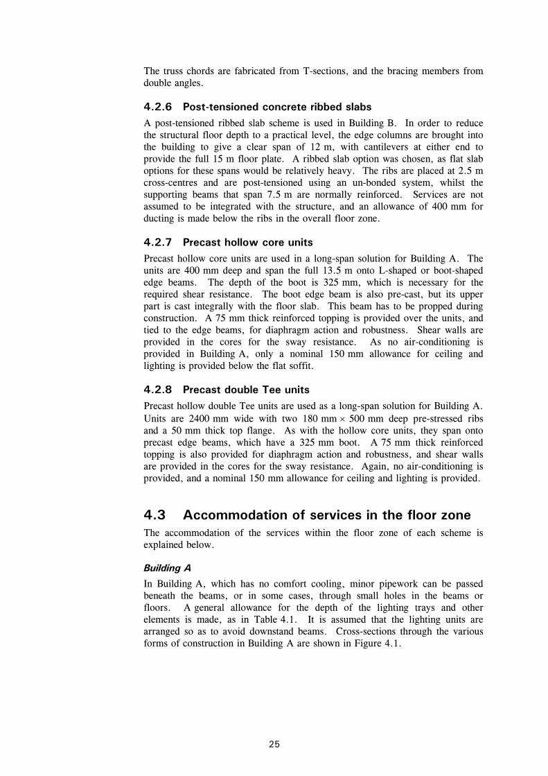
4.2.7 Precast hollow core units Precast hollow core units are used in a long-span solution for Building A. The units are 400 mm deep and span the full 13.5 m onto L-shaped or boot-shaped edge beams. The depth of the boot is 325 mm, which is necessary for the required shear resistance. The boot edge beam is also pre-cast, but its upper part is cast integrally with the floor slab. This beam has to be propped during construction. A 75 mm thick reinforced topping is provided over the units, and tied to the edge beams, for diaphragm action and robustness. Shear walls are provided in the cores for the sway resistance. As no air-conditioning is provided in Building A, only a nominal 150 mm allowance for ceiling and lighting is provided below the flat soffit.
4.2.8 Precast double Tee units Precast hollow double Tee units are used as a long-span solution for Building A. Units are 2400 mm wide with two 180 mm × 500 mm deep pre-stressed ribs and a 50 mm thick top flange. As with the hollow core units, they span onto precast edge beams, which have a 325 mm boot. A 75 mm thick reinforced topping is also provided for diaphragm action and robustness, and shear walls are provided in the cores for the sway resistance. Again, no air-conditioning is provided, and a nominal 150 mm allowance for ceiling and lighting is provided.
4.3 Accommodation of services in the floor zone The accommodation of the services within the floor zone of each scheme is explained below.
Building A
In Building A, which has no comfort cooling, minor pipework can be passed beneath the beams, or in some cases, through small holes in the beams or floors. A general allowance for the depth of the lighting trays and other elements is made, as in Table 4.1. It is assumed that the lighting units are arranged so as to avoid downstand beams. Cross-sections through the various forms of construction in Building A are shown in Figure 4.1.

P137v02d10.doc 26 Printed 08/11/04
Table 4.1 Depth allowance for ceiling and services below the structure in Building A
Item Flat Soffit Downstand Beams
Allowance for imposed load deflections 25 25
Allowance for fire protection none 25
Lighting units *
Lighting tray 125 50
Ceiling depth 50
Total depth allowance 150 mm 150 mm
* Lighting units off-set from line of beams
Building B
In Building B, comfort cooling is provided by a Fan Coil system. The Fan Coil Units (FCUs) and ductwork are accommodated either below the structure, or, alternatively, integrated within the structural depth. The depth of the FCUs and their hangers is taken as 400 mm. It is assumed that the lighting units are arranged to avoid the FCUs and major ducts. The maximum depth or diameter of air distribution duct (including insulation) is taken as 400 mm, and for
Downstand Beam
150
D = 300
Slimdek or Flat Slab
Raised floor150
50
Raised floor
130
5050
LightingCeiling
50LightingCeiling
7525
600 mm
Raised floor 150
Long Span Beam
130
505050
LightingCeiling
D = 370
800 mm
D = 570 or 670
1000 or 1100 mm
Figure 4.1 Building A - Cross-sections through the various structural systems showing the services zones and beam depth allowance

P137v02d10.doc 27 Printed 08/11/04
efficient design of the ducts, their width:depth ratio would not normally exceed two. In flat or ribbed soffit systems, the ducts and FCUs occupy the same horizontal zone.
A general allowance for the depth of the air-distribution systems and other elements is made for all generic systems, as in Table 4.2. Cross-sections through the various forms of construction showing the floor zones are illustrated in Figure 4.2. In practice, it may be possible to justify a slight reduction in these depth allowances for particular building forms and uses.
In Table 4.2, it is assumed that the FCUs are accommodated between the beams where downstand beams are used. Hence, the controlling dimension is that of the ducts below the beams. In the systems with a flat soffit, it is the depth of the FCUs and lighting units that controls the overall depth of the construction.
In the Slimdek® system, it is possible to partially integrate services between the ribs in the floor[3], and it is assumed that pipes and small ducts pass through the ASB sections and between the deck ribs. The zone for structure and services is therefore minimised.
The long-span options offering the facility for structure-service integration are designed for the size of air-distribution ducts (including insulation) required in a building of this form.
Most of the schemes have been designed using rectangular ducting in order to achieve the minimum floor depth for the required air movement. However, multiple circular ducts were used in the cellular beam options, to suit the regular circular openings that are provided in these beams. An example of a cellular beam with circular ducting is shown in Figure 4.3.
Table 4.2 Depth allowance for ceiling and services below the structure in Building B
Item Flat soffit Downstand beams
Integration of beams and services
Ceiling and lighting 125† 100† 100*
FCU and attachments n/c n/c
Service ducts
400
400 n/c
Fire protection and deflection 25 50 50
Total depth allowance 550 mm 550 mm 150 mm
* Lighting units off-set from line of beams
† Lighting units off-set from ducting
n/c Not critical
More detailed guidance on integration of structure and services in modern commercial buildings is given in recent SCI publications[3] [28] [4], the first two of which also give practical service layouts for various building forms and structural systems.

P137v02d10.doc 28 Printed 08/11/04
Downstand Beam
Fan CoilUnit
150
400
50
50
D = 300
Slimdek or Flat Slab
Raised floor
DuctingFan CoilUnit
150
140
D = 360
400
50
5050
Lighting
LightingCeiling
Ceiling 50Ducting + insulation
Raised floor
1200 mm
1000 mm
Raised floor
Service Integration - Long Span Beam
150
140
50
Ducting + insulation400 dia.
D = 660 or 760
1100 or 1200 mm
5050
LightingCeiling
Figure 4.2 Building B - Cross-sections through the various structural systems, showing services zones and beam depth allowance
Figure 4.3 Cellular beams with circular ducting

P137v02d10.doc 29 Printed 08/11/04
5 PLANS, CROSS-SECTIONS AND SUMMARY OF STRUCTURAL SCHEMES DEVELOPED IN THE STUDY
The structural schemes developed for Buildings A and B are described below. Plan drawings show typical internal bays and the core area at the ends of the buildings. Typical cross-sections of the floors are also given. The members have been designed for the criteria presented in Section 3.2.
The beam and column sizes, together with the construction depth and other features of the designs, are scheduled in the drawings of representative parts of a typical floor.
5.1 Building A The structural schemes developed for Building A include both the short- and long-span options listed in Section 4. Because of the modest requirement for services, only composite beams with small web openings and composite cellular beams are used for the long-span steel options.
The drawings of the part of the building adjacent to one core are presented in Figure 5.1 to Figure 5.6 for the steel options, and in Figure 5.7 to Figure 5.9 for the concrete options. Alternative Slimdek® options are presented in Figure 5.2 and Figure 5.3.
5.2 Building B The structural schemes developed for Building B concentrate mostly on the long-span options. Because of the requirement for large service ducts, a range of systems offering the facility for structure-service integration is examined.
The drawings of one quarter of the building plan are presented in Figure 5.10 to Figure 5.19 for the steel/composite options, and in Figure 5.18 and Figure 5.19 for the concrete options. Alternative Slimdek® options are presented in Figure 5.10 and Figure 5.11, and alternative cellular beam options are presented in Figure 5.13 and Figure 5.14.
5.3 Summary of the designs The structural designs may be summarised in terms of steel weight and floor depth (also including the weight of steel in the non-frame items). This information is summarised in Table 5.1 and Table 5.2 for the structural options used in both buildings, and is expressed in items of gross floor area (GFA). Net floor areas are approximately 80% of GFA.
Although relevant, the relative merits of the various options cannot be determined readily from Table 5.1 and Table 5.2. For example, the weight of the steel is only a simplistic measure of efficiency, as the costs of fire

P137v02d10.doc 30 Printed 08/11/04
protection, cladding and ease of distribution of services should be included in the broad assessment of costs.
Table 5.1 Summary of the structural designs of Building A included in this study
Structural Form Steelwork weight per unit floor area
BUILDING A
Structure deptha (mm)
Overall floor zoneb (mm)
Building heightc
(m)
Area fire protection (m2 /m2
floor area) Basic frame
(kg/m2)
Additional steelworkd
(kg/m2)
Total steelwork (kg/m2)
Slimflor® + Pre-Cast Slabs with downstand edge beams
275 600 13.2 0.43 38.8 8.2 47.0
Slimdek® (SD225 Deep Deck (Propped)) with downstand beams
311 600 13.2 0.44 34.1 8.2 42.3
Slimdek® (SD225 Deep Deck, Unpropped) with integral edge beams
317 600 13.2 0.36 41.1 8.2 49.3
Composite Beams + Composite Slab
482 800 14.0 0.66 35.5 8.2 43.7
Cellular Beams + Composite Slab
790 1100 15.2 0.90 44.4 8.2 52.6
Composite Beams with Web Openings
663 1000 14.8 0.76 47.5 8.2 55.7
Reinforced Concrete Flat Slab
300 600 13.2 - - 8.2 8.2
Pre-cast Concrete – Hollow Core Units
475 800 14.0 - - 8.2 8.2
Pre-cast Double Tee Units
575 900 14.4 - - 8.2 8.2
a includes steel beam, flange plates (if any) and slab
b includes 150 mm raised floor and 150 mm for services below the structure (see Table 4.1)
c excludes roof
d includes steel required for wind posts, cladding rails and pitched roof

P137v02d10.doc 31 Printed 08/11/04
Table 5.2 Summary of the structural designs of Building B included in this study
Structural Form Steelwork weight per unit floor area
BUILDING A
Structure deptha (mm)
Overall floor zoneb (mm)
Building heightc
(m)
Area fire protection (m2 /m2
floor area) Basic frame
(kg/m2)
Additional steelworkd
(kg/m2)
Total steelwork (kg/m2)
Slimdek® (SD225 Deep Deck (Unpropped)) with downstand edge beams
322 1000 29.6 0.42 38.4 2.0 40.4
Slimdek® (SD225 Deep Deck’ Propped) with RHS Slimflor® edge beams
326 1000 29.6 0.31 41.4 2.0 43.4
Composite Beams + Composite Slab
488 1200 31.2 0.69 35.4 2.0 37.4
Cellular Beams as Secondary Beams + Composite Slab
798 1100 30.4 0.74 44.4 2.0 46.4
Cellular Fabricated Beams as Primary Beams + Composite Slab
900 1200 31.2 0.74 43.5 2.0 45.5
Tapered Fabricated Girders
900 1200 31.2 0.75 43.4 2.0 45.4
Haunched Composite Beams
593 1250 31.6 0.70 42.1 2.0 44.1
Composite Trusses 980 1300 32.0 0.80 46.5 2.0 48.5
Reinforced Concrete Flat Slab
300 1000 29.6 - - 2.0 2.0
Post-tensioned Ribbed Slab
500 1200 31.2 - - 2.0 2.0
a includes steel beam and slab
b includes 150 mm raised floor and allowances for services below the structure (see Table 4.2)
c excludes atrium roof and plant room
d includes steel required for plantroom and atrium roof

P137v02d10.doc 32 Printed 08/11/04
SECTION A-A
PART PLAN
Floor zone= 150 mm raised floor
Side bracing
Wal
l br
acin
g
Toilets
203
UC60 (1
&2)
203
UC46 (1
&2)
203
UC46 (3
&4)
203
UC60 (1
&2)
203
UC60 (1
&2)
203
UC71 (1
&2)
203
UC52 (3
&4)
203
UC46 (3
&4)
203
UC46
(3&4)
203
UC46
(3&4)
203
UC46 (3
&4)
203
UC46
(1&2)
203
UC60
(1&2)
203
UC46
(3&4)
203
UC71
(1&2)
203
UC52 (3
&4)203x133 UB25
S275
203x133 UB25S275
Stairs Lifts &
Side bracing
406 x 178 UB60S275
406 x 178 UB60 S275
406 x
178 U
B74
S275
406 x
178 U
B60
S275 406 x
178 U
B54
S275
254 x
102 U
B25
S275
S355
S355
S355
S355
S355
S355 A
A
203
UC60
(1&2)
203
UC46 (3
&4)
S355
305 x
165 U
B40
S275
254 x
102 U
B25
S275
254 x
102 U
B25
S275
S355
S355
406 x 178 UB54S275
406 x 178 UB54S275
60
≈
254 UC89 S355Slimflor beam
254 UC89 S355Slimflor beam
= 560 mm 600 mm+ 150 mm ceiling & lighting+ 260 mm p.c. unit & topping
Hollow core units+ 60 mm
NWC topping200
p.c.
unit
A142 mesh
T12 x 1200lg tie bars@600 ctrs throughholes in web
NWC topping
254 UC89 460 x 15thk plate
6.0 m
6.0
m7.5
m
3.0 m 3.0 m
Figure 5.1 Building A – Slimflor® beams and pre-cast slabs with downstand edge beams
P137v02d10.doc 33 Printed 08/11/04
@ 600 ctrs.
deep
dec
k
SECTION A-A
PART PLAN
70
225
SD
225
Side bracing
Wal
l br
acin
g
Toilets
203
UC60 (1
&2)
203
UC46
(1&2)
203
UC46 (3
&4)
203
UC60 (1
&2)
203
UC60 (1
&2)
203
UC71 (1
&2)
203
UC52
(3&4)
203
UC46
(3&4)
203
UC46
(3&4)
203
UC46
(3&4)
203
UC46 (3
&4)
203
UC46
(1&2)
203
UC60
(1&2)
203
UC46
(3&4)
203
UC71
(1&2)
203
UC52 (3
&4)203x133 UB25
S275
203x133 UB25S275
Stairs Lifts &
Side bracing
35
P
A
A
P P
Slab
406 x 178 UB60 S275 406 x 178 UB54S275
S355
S355
S355
S355
S355
203
UC60
(1&2)
203
UC46 (3
&4)
S355
S355
S355
S355
406 x
178 U
B74 S
275
305 x
165 U
B40 S
275
406 x
178 U
B60 S
275
= deck requirespropping duringconstruction inthis span
406 x
178 U
B54 S
275
165 x
152 T
@ 2
0 k
g/m
S275
165 x
152 T
@ 2
0 k
g/m
S275
165 x
152 T
@ 2
0 k
g/m
S275
Floor zone= 150 mm raised floor
+ 150 mm ceiling & lighting
406 x 140 UB46S275
406 x 140 UB46S275
+ 295 mm slab
= 595 mm 600 mm≈
A142 mesh
T16's
NWC slab
280 ASB100
6.0 m
6.0
m7.5
m
3.0 m 3.0 m
280 ASB 100S355
280 ASB 100S355
Figure 5.2 Building A – Slimdek® (SD 225 deep deck with propped 7.5 m span) with downstand edge beams

P137v02d10.doc 34 Printed 08/11/04
@ 600 ctrs.
deep
dec
k
SECTION A-A
AA
PART PLAN
225
SD
225
Side bracing
Wal
l br
acin
g
Toilets
203
UC60
(1&2)
203
UC46
(1&2)
203
UC46
(3&4)
203
UC60
(1&2)
203
UC60
(1&2)
203
UC71
(1&2)
203
UC52
(3&4)
203
UC46
(3&4)
203
UC46
(3&4)
203
UC46
(3&4)
203
UC46
(3&4)
203
UC46
(1&2)
203
UC60 (1
&2)
203
UC46
(3&4)
203
UC71
(1&2)
203
UC52
(3&4)
280 A
SB.1
00
280 A
SB.1
00
533 x
210 U
B92 S
275
406 x 178 UB60 S275
200 ASB 74
203x133 UB25S275
Stairs Lifts &
Slab
Side bracing
280 A
SB136
S355
S355
S355
S355
S355
S355
203
UC60
(1&2)
203
UC46 (3
&4)
S355
S355
S355
S355
406 x
178 U
B74 S
275
406 x
140 U
B46
406 x
178 U
B60 S
275
165 x 152 T @20 kg/mS275
Floor zone= 150 mm raised floor
+ 150 mm ceiling & lighting
305 x 165 UB40S275
305 x 165 UB40 S275 305 x 165 UB40 S275
29
+ 295 mm slab
= 595 600 mm≈
70A142 mesh
T16's
NWC slab
280 ASB136
3.0 m 3.0 m6.0 m
6.0
m7.5
m
280x133 UB25S275
Figure 5.3 Building A – Slimdek® (SD 225 deep deck, unpropped)
with integral edge beams

P137v02d10.doc 35 Printed 08/11/04
SECTION A-A
PART PLAN
Floor zone= 150 mm raised floor
≈
Stairs
Side bracing
Side bracing
Slab
Wal
l br
acin
g
203
UC60 (1
&2)
203
UC60
(1&2)
203
UC46
(1&2)
203
UC46
(1&2)
203
UC46 (3
&4)
203
UC60
(1&2)
203
UC60
(1&2)
203
UC71
(1&2)
203
UC71
(1&2)
203
UC52
(3&4)
203
UC52
(3&4)
203
UC46 (3
&4)
203
UC46
(3&4)
203
UC46 (3
&4)
203
UC46
(3&4)
203
UC46
(3&4)
203x133 UB25
203x133 UB25
Lifts &Toilets
Void A
A
Slab
356 x
127 U
B33
S275
356 x
127 U
B33
S275
203
UC46
(3&4)
203
UC60
(1&2)
375 x 127 UB39S275
356 x 171 UB51S275
356 x 171 UB45S275
356 x 127 UB33S275
356 x 127 UB33S275
+ 130 mm slab+ 352 mm beam
= 782 mm 800 mm
S355
S355
S355
S355
S355
S355
S355
S355
S355
254 x
146 U
B31 S
275
254 x
146 U
B31 S
275
254 x
146 U
B31 S
275
254 x
146 U
B31 S
275
254 x
146 U
B31 S
275
406 x
178 U
B60 S
275
406 x
178 U
B60 S
275
356 x 171 UB45 S275
457 x
191 U
B67 S
275
+ 150 ceiling & lighting
6.0 m
6.0
m7.5
m
130
352
2 No. 19 dia. x 100lg.studs @300 ctrs.A142 mesh
3.0 m 3.0 m
356 x 171 UB45
NWC slab
Transversebars T12 @ 300 ctrs
Dec
king
6
00.9
mm
thk
.
Figure 5.4 Building A – Composite beams and composite slab

P137v02d10.doc 36 Printed 08/11/04
Circularopening
PART PLAN
Side bracing
Wal
l br
acin
g
Toilets
203
UC46
(3&4)
203
UC46
(3&4)
203
UC46
(1&2)
S275
203x133 UB25S275
203x133 UB25S275
Stairs Lifts &
Side bracing
AA
Slab
203
UC46 (3
&4)
254
UC73
(1&2)
457 x 152 UB52S275
203
UC60 (1
&2)
203
UC46
(3&4)
356 x 171 UB51S275
Slab
254 x
146 U
B31 S
275
254 x
146 U
B31 S
275
457 x 152 UB52S275
254
UC73 (1
&2)
B
B
254
UC73
(1&2)
203
UC52 (3
&4)
203
UC46 (1
&2)
203
UC46
(3&4)
NWCslab
254
UC73 (1
&2)
203
UC52
(3&4)
S355
S355 S3
55
203
UC60
(1&2)
203
UC46
(3&4)
S355
S355
S355
S355
SECTION A-A
457 x
191 U
B67 S
275
406 x
178 U
B60 S
275
254 x
146 U
B31 S
275
356 x 127 UB33 S275
356 x 171 UB45 S275
457 x
191 U
B74 S
275 +
457 x
191 U
B82 S
275
Cel
lula
r be
am
≈
406 x
178 U
B60 S
275
=1090 mm 1100 mm
Floor zone= 150 mm raised floor+ 130 mm slab
6.0
m7.5
m
6.0 m
130
2 No. 19Ø x 100lgstuds @ 300ctrs
3.0 m 3.0 m
575
20 N
o. h
oles
@ 6
50ct
rs.
650660
A193 mesh
+ 660 mm beam+ 150 mm ceiling & lighting
Decking 0.9 mm thk
450
Figure 5.5 Building A – Cellular beams and composite slab

P137v02d10.doc 37 Printed 08/11/04
Rectangularopening
PART PLAN
Side bracing
Wal
l br
acin
g
Toilets
203
UC46
(3&4)
203
UC46
(3&4)
203
UC46
(1&2)
S275
203x133 UB25S275
203x133 UB25S275
Stairs Lifts &
Side bracing
AA
Slab
203
UC46
(3&4)
254
UC73
(1&2)
457 x 152 UB52S275
203
UC60
(1&2)
203
UC46
(3&4)
356 x 171 UB51S275
Slab
254 x
146 U
B31 S
275
254 x
146 U
B31 S
275
457 x 152 UB52S275
254
UC73
(1&2)
B
B
254
UC73
(1&2)
203
UC52
(3&4)
203
UC46
(1&2)
203
UC46
(3&4)
NWCslab
SECTION A-A
254
UC73
(1&2)
203
UC52
(3&4)
Sec
tion
B -
B
≈
533 x
210 U
B92
S275
3 h
oles
req
d
S355
S355
S355
203
UC60
(1&2)
203
UC46
(3&4)
S355
S355
S355
S355
457 x
191 U
B67 S
275
406 x
178 U
B60 S
275
254 x
146 U
B31 S
275
356 x 127 UB33 S275
406 x
178 U
B60 S
275
356 x 171 UB45 S275
= 963 mm 1000 mm
Floor zone= 150 mm raised floor+ 130 mm slab
6.0
m7.5
m
6.0 m
130
533 x 210 UB92
2 No. 19Ø x 100lgstuds @ 300ctrs
3.0 m 3.0 m
5.0
m
450
250
140
6.7
5 m
8.5
m
A193 mesh
+ 150 mm ceiling & lighting+ 533 mm beam5
33250
Decking 0.9 mm thk
Figure 5.6 Building A – Composite beams with web openings

P137v02d10.doc 38 Printed 08/11/04
Part Plan
Stairs Toilets
Void
A
A
Section A - A
300 mm thk R.C. slab
Lift
7.5 m
6.0 m6.0 m
400 x 400 column
Core area
600 x 200column
6.0 m
300
Crankeddownstandbeam 500 dpx 200 wide
250 thk RC shear walls
Floor zone= 150 mm raised floor+ 300 mm concrete slab+ 150 mm ceiling & lighting 600 mm
Figure 5.7 Building A – Reinforced concrete flat slab

P137v02d10.doc 39 Printed 08/11/04
B B
Part Plan
Stairs
Lift
Toilets
300 thk.R.C. slab
A
A
7.5 m
6.0 m6.0 m
6.0 m
400 x 400 column
Crankedbeam
250 thk R.C. shear wall
1200 widex 400 deepHollow Core Units+ 75 mm screed
Core area
600 x 300column
Void
≈
Floor zone= 150 mm raised floor+ 75 mm screed+ 400 mm hollow core units+ 150 mm ceiling & lighting 775 mm 800 mmSection A - A Section B - B
325
500
200
725
75
1200
400
Figure 5.8 Building A – Precast hollow core units

P137v02d10.doc 40 Printed 08/11/04
B B
Part Plan
Void
Stairs
Lift
Toilets
300 thk.R.C. slab
A
A
7.5 m
6.0 m6.0 m
6.0 m
400 x 400 column
600 x 300column
Crankedbeam
2400 widex 500 deepDouble Tee Units+ 75 mm screed
Core area
250 thk R.C. shear wall
Section A - A Section B - B
325 825
500
75
500
50
200 2400180
≈
Floor zone= 150 mm raised floor+ 75 mm screed+ 500 mm Tee units+ 150 mm ceiling & lighting 875 mm 900 mm
Figure 5.9 Building A – Precast double Tee units

P137v0
2d1
0.doc
41
Printed 0
8/1
1/0
4
CL
CL
Column schedule
A
B
225
deep
dec
k
Floor zone
A
A
A
CL
15.0 m15.0 m
7.5
m7.5
m
22.5
m
LWC slab
305 UC97 (1 & 2)
SD
225
Side
bra
cing
7.5
m
203 x
133
UB25 S
275
Void
254 x 146 UB31S275
5.0 m
A
ACL
B
B
B
A A5.0 m 5.0 m
280 A
SB 1
05
S355
280 A
SB 1
05
S355
254 x 146 UB31S275
Toilets
Slab
203x133UB25 S275
Stairs
6.0 m
A
A
Wall bracing
406x
178 U
B67
S275
406x
178 U
B67
S275
B
B
B
280 A
SB 1
05
S355
280 A
SB 1
05
S355
305 x 165 UB40S275
305 x 165 UB40S275
280 A
SB124
S355
280 A
SB124
S355
C C165 x 152 'T'20 kg/m S275
280 A
SB124
S355
280 A
SB124
S355
C
Slab
203 x 133UB25 S275
203 x 133UB25 S275
Void
Lift
Lift406 x
178 U
B67
S275
406 x
178 U
B67
S275
A
A
280 A
SB124
S355
C
A
A
280 A
SB124
S355
C
305 x 165 UB40S275
305 x 165 UB40S275
165 x 152 'T'20 kg/m S275
305 x 165 UB40S275
305 x 165 UB40S275
165 x 152 'T'20 kg/m S275
6.0 m 6.0 m
A A
(S355)
(S355)
(S355)
C 305 UC118 (1 & 2)
254 UC73 (3,4 & 5)203 UC52 (6,7 & 8)
305 UC97 (1 & 2)
203 UC60 (6,7 & 8)254 UC89 (3,4 & 5)
305 UC97 (3,4 & 5)254 UC73 (6,7 & 8)
A193 mesh34 7
5
280 A
SB105
S355
280 A
SB105
S355
T20's @ 600 ctrs+T16 'L' bar forend anchorage
305 x 165 UB40S275
305 x 165 UB40S275
305 x 165 UB40S275
406x
178 U
B67
S275
406x
178 U
B67
S275
280 ASB 74S355
280 ASB 74S355
280 A
SB105
S355
280 A
SB74
S355
280 A
SB74
S355
280 A
SB74
S355
280 A
SB 1
05
S355
280 A
SB 1
05
S355
280 ASB 74S355
280 ASB 74S355
165 x 152 'T'20 kg/m S275
165 x 152 'T'20 kg/m S275
165 x 152 'T'20 kg/m S275
165 x 152 'T'20 kg/m S275
165 x 152 'T'20 kg/m S275
165 x 152 'T'20 kg/m S275
165 x 152 'T'20 kg/m S275
Slab
= 150 mm raised floor+ 300 mm floor slab+ 400 Fan Coil Unit/duct+ 150 ceiling & lighting=1000 mm
280 ASB105
PART PLAN
SECTION A-A
Figure 5.10 Building B – Slimdek® (SD 225 deep deck, unpropped) with downstand edge beams

P137v0
2d1
0.doc
42
Printed 0
8/1
1/0
4
CL
CL
Column schedule
A
B
225
deep
dec
k
Floor zone
A A
A
A
A A
A
A
A
A
A
B B B
B
PPP P
PPP P
B
A
B
B
A
P
P
P
CL
CL
15.0 m15.0 m
7.5
m7.5
m
22.5
m
LWC slab
305 UC97 (1 & 2)254 UC89 (3,4 & 5)203 UC71 (6,7 & 8)
305 UC137 (1 & 2)305 UC118 (3,4 & 5)254 UC73 (6,7 & 8)
7.5 m 7.5 m7.5 m 7.5 m
165 x 152 'T' 165 x 152 'T'165 x 152 'T'165 x 152 'T'
3.0
m3.0
m3.0
m1.5
m
165 x 152 'T'
165 x 152 'T'
165 x 152 'T'
165 x 152 'T'
4.5
m
203 x
133
203 x
133
203 x
133
203 x
133
= decking requirespropping duringconstruction inthis bay
SD
225
Toilets
Wall bracing
Stairs
Void
Lift Lift
Voi
d
Slab
Slab
400 x
200 R
HS
x 8 m
m t
hick
S355
+ 1
5 m
m t
hick
pla
te
400 x
200 R
HS
x 8 m
m t
hick
S355
+ 1
5 m
m t
hick
pla
te
250 x 150 RHSx 8mm thick S355
+15 mm thick plate
250 x 150 RHSx 8mm thick S355
+15 mm thick plate
400 x
200 R
HS
x 8 m
m t
hick
S355
+ 1
5 m
m t
hick
pla
te
280 A
SB124
S355
280 A
SB124
S355
280 A
SB124
S355
280 A
SB124
S355
250 x 150 RHSx 8mm thick S355
+15 mm thick plate
250 x 150 RHSx 8mm thick S355
+15 mm thick plate
250 x 150 RHSx 8mm thick S355
+15 mm thick plate
20kg/m S275 20kg/m S275 20kg/m S275 20kg/m S275
250 x 150 RHSx 8mm thick S355
+15 mm thick plate
356 x 171 UB51S355
356 x 171 UB51S355
254 x 146 UB37S355
254 x 146 UB37 S355
254 x 146 UB37S355
280 A
SB124 S
355
280 A
SB124 S
355
400 x
200 R
HS
x 8 m
m t
hick
S355
+ 1
5 m
m t
hick
pla
te280 A
SB124
S355
280 A
SB124
S355
280 A
SB124
S355
280 A
SB124
S355
75
34A193 mesh
T20's @ 600 ctrs+T16 'L' bar forend anchorage
280 ASB 124
(S355)
(S355)
UB25 S
275
UB25 S
275
UB25 S
275
20kg/m S275
20kg/m S275
20kg/m S275
UB25 S
275
400 x
200 R
HS
x 8 m
m t
hick
S355
+ 1
5 m
m t
hick
pla
te
400 x
200 R
HS
x 8 m
m t
hick
S355
+ 1
5 m
m t
hick
pla
te
Side
bra
cing
20kg/m S275
= 150 mm raised floor+ 300 mm floor slab+ 400 mm Fan Coil Units/ducts+ 150 mm ceiling & lighting=1000 mm
PART PLAN
SECTION A-A
Figure 5.11 Slimdek® (SD 225 deep deck, propped) with RHS Slimflor® edge beams
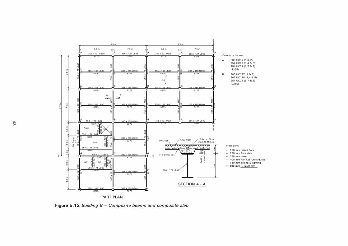
P137v0
2d1
0.doc
43
Printed 0
8/1
1/0
4
CL
CL
A
A A
CL
15.0 m15.0 m
7.5
m7.5
m
22.5
m
3.0
m3.0
m3.0
m1.5
m4.5
m
203 x
133
203 x
133
203 x
133
Side
bra
cing
Toilets
Stairs
Void
Lift Lift
Voi
d
D
PART PLAN
Column schedule
A
B
305 UC97 (1 & 2)254 UC89 (3,4 & 5)
203 x
133
UB25 S
275
UB25 S
275
UB25 S
275
UB25 S
275
356 x 171 UB67S275
(S355)
(S355)
254 UC71 (6,7 & 8)
305 UC137 (1 & 2)305 UC118 (3,4 & 5)254 UC73 (6,7 & 8)
B B
356 x
171 U
B57
S355
7.5 m7.5 m7.5 m7.5 m
356 x
171 U
B57
S355
356 x 127 UB39S275
356 x 127 UB39S275
356 x 127 UB39S275
356 x 127 UB39S275
305 x 165 UB40S275
305 x 165 UB40S275
305 x 165 UB40S275
356 x
171 U
B57
S355
356 x
171 U
B57
S355
B
305 x 165 UB40S275
305 x 165 UB40S275
305 x 165 UB40S275
356 x
171 U
B57
S355
356 x
171 U
B57
S355
B
305 x 165 UB40S275
305 x 165 UB40S275
305 x 165 UB40S275
356 x
171 U
B57
S355
356 x
171 U
B57
S355
305 x 165 UB40S275
305 x 165 UB40S275
305 x 165 UB40S275
A A
356 x 127 UB39S275
356 x 127 UB39S275
A A A A
A ABB
A
A
356 x
171 U
B57
S355
356 x
171 U
B57
S355
356 x 171 UB67S275
375 x 171 UB45S355
CL
130
358
60
Dec
king
1.2
mm
thi
ck
A193 mesh 19 dia. x 100 lgstuds @ 150 crs
305 x 165 UB40S275
305 x 165 UB40S275
305 x 165 UB40S275
305 x 165 UB40S275
305 x 165 UB40S275
356 x 171 UB67S275
356 x 171 UB45S355
305 x 165 UB40S275
356 x
171 U
B51
S275
356 x
171 U
B51
S275
356 x
171 U
B51
S275
356 x
171 U
B51
S275
356 x
171 U
B51
S275
356 x
171 U
B51
S275
Slab
356 x 171 UB57
LWC slab
T12 @ 300 ctrs
Floor zone
+ 130 mm floor slab= 150 mm raised floor
+ 358 mm beam
+ 150 mm ceiling & lighting≈=1188 mm 1200 mm
+ 400 mm Fan Coil Units/ducts
SECTION A - A
Figure 5.12 Building B – Composite beams and composite slab

P137v0
2d1
0.doc
44
Printed 0
8/1
1/0
4
CL
CL
A
A A
A A
CL
15.0 m15.0 m
7.5
m7.5
m
22.5
m
3.0
m3.0
m3.0
m1.5
m4.5
m
203 x
133
203 x
133
203 x
133
Side
bra
cing
Toilets
Wall bracing
Stairs
Void
Lift Lift
Voi
d
B B B B3.75 3.75 3.75 3.75 3.75 3.75 3.75 3.75
C C B B
D
A
B
Column schedule
A
B
305 UC97 (1 & 2)254 UC89 (3,4 & 5)203 UC60 (6,7 & 8)
356 UC153 (1 & 2)356 UC129 (3,4 & 5)305 UC97 (6,7 & 8)
C
305 UC97 (6,7 & 8)
356 UC177 (1 & 2)356 UC153 (3,4 & 5)
D305 UC97 (3,4 & 5)305 UC97 (6,7 & 8)
Floor zone
305 UC137 (1 & 2)
≈
130LWC slab
Dec
king
1.2
mm
thk
SECTION A-A
+ 130 mm floor slab
60
= 150 mm raised floor
457 x 191 UB74S355
457 x 191 UB74S355
457 x 191 UB74S355
457 x 191 UB74S35576.1 x 3.2 m
m thick
RHS S275
76.1 x 3.2 mm thick
RHS S275
76.1
x 3
.2 m
m th
ick
RHS
S275
76.1
x 3
.2 m
m th
ick
RHS
S275
305 X 305 UC118S355
203 x
133
UB25 S
275
UB25 S
275
UB25 S
275
UB25 S
275
356 x 171 UB67S275
305 x
305 U
C97 S
355
305 x
305 U
C97 S
355
305 X 305 UC97S355
(S355)
(S355)
(S355)
(S355)
2 No. 19Ø X 100 lg studs @ 300 ctrs
305 X 305 UC97S355
305 X 305 UC97S355
305 x 165 UB40S275
305 x 165 UB40S275
305 x 165 UB40S275
356 x 171 UB67S275
356 x 171 UB45S355
356 x 171 UB45S355
457 x 191 UB74S355
457 x 191 UB74S355
668
+ 668 mm beam
=1098 mm 1100 mm
600600 24 No. holes 400 dia. @ 600 ctrs
15.0 m (79.7 Kg/m)
356 x
171 U
B51
S275
356 x
171 U
B51
S275
356 x
171 U
B51
S275
356 x
171 U
B51
S275
356 x
171 U
B51
S275
356 x
171 U
B51
S275
457 x
152 U
B67/5
33 x
210 U
B92
Cel
lula
r be
am 6
68 m
m d
eep
S355
457 x
152 U
B67/5
33 x
210 U
B92
Cel
lula
r be
am 6
68 m
m d
eep
S355
457 x
152 U
B67/5
33 x
210 U
B92
Cel
lula
r be
am 6
68 m
m d
eep
S355
457 x
152 U
B67/5
33 x
210 U
B92
Cel
lula
r be
am 6
68 m
m d
eep
S355
457 x
152 U
B67/5
33 x
210 U
B92
Cel
lula
r be
am 6
68 m
m d
eep
S355
457 x
152 U
B67/5
33 x
210 U
B92
Cel
lula
r be
am 6
68 m
m d
eep
S355
457 x
152 U
B67/5
33 x
210 U
B92
Cel
lula
r be
am 6
68 m
m d
eep
S355
457 x
152 U
B67/5
33 x
210 U
B92
Cel
lula
r be
am 6
68 m
m d
eep
S355
+ 150 mm ceiling & lighting
Slab
457 x 152 UB67
533 x 210 UB92
2 layers ofA193 mesh
400
Circ
ular
ope
ning
PART PLAN
Figure 5.13 Building B – Cellular beams (fabricated from hot-rolled sections - long-span secondary beams) and composite slab

P137v0
2d1
0.doc
45
Printed 0
8/1
1/0
4
Column schedule
A
B
305 UC97 (1 & 2)254 UC89 (3,4 & 5)203 UC60 (6,7 & 8)
356 UC153 (1 & 2)356 UC129 (3,4 & 5)305 UC97 (6,7 & 8)
C
305 UC97 (6,7 & 8)
356 UC177 (1 & 2)356 UC153 (3,4 & 5)
D305 UC97 (3,4 & 5)305 UC97 (6,7 & 8)
Floor zone
305 UC137 (1 & 2)
SECTION A-A
+ 130 mm floor slab= 150 mm raised floor
(S355)
(S355)
(S355)
(S355)
CL
CL
A
A A
CL
15.0 m15.0 m
7.5
m7.5
m
22.5
m
3.0
m3.0
m3.0
m1.5
m4.5
m
203 x
133
203 x
133
203 x
133
Side
bra
cing
Toilets
Stairs
Void
Lift Lift
Voi
d
D
PART PLAN
203 x
133
UB25 S
275
UB25 S
275
UB25 S
275
UB25 S
275
356 x 171 UB67S275
7.5 m7.5 m7.5 m7.5 m
356 x 127 UB39S275
356 x 127 UB39S275
356 x 127 UB39S275
305 x 165 UB40S275
305 x 165 UB40S275
305 x 165 UB40S275
305 x 165 UB40S275
305 x 165 UB40S275
305 x 165 UB40S275
305 x 165 UB40S275
305 x 165 UB40S275
305 x 165 UB40S275
305 x 165 UB40S275
305 x 165 UB40S275
305 x 165 UB40S275
A A
A
A356 x 171 UB67
S275
375 x 171 UB45S355
CL
B
B
356 x 127 UB39S275
356 x 127 UB39S275
356 x 127 UB39S275
BBB
BC305 x 165 UB40
S275
305 x 165 UB40S275
305 x 165 UB40S275
305 x 165 UB40S275
305 x 165 UB40S275
B
356 x
171 U
B57
S355
356 x
171 U
B57
S355
130LWC slab
20
15
770
200
400
+ 770 mm beam
356 x
171 U
B51
S275
356 x
171 U
B51
S275
356 x
171 U
B51
S275
356 x
171 U
B51
S275
356 x 171 UB67S275
356 x 171 UB45S355
305 X 165 UB40S275
356 x
171 U
B51
S275
356 x
171 U
B51
S275
15.0 m
15
250 20
Slab
+ 150 mm ceiling & lighting=1200 mm
900 9001200 1200 12005 No. holes 400 dia.@ 600 ctrs
5 No. holes 400 dia.@ 600 ctrs
5 No. holes 400 dia.@ 600 ctrs
5 No. holes 400 dia.@ 600 ctrs
2 layers ofA193 mesh
19Ø X 100 lg studs @ 150 ctrs
Decking1.2 mm thk
Fabr
icat
ed c
ellu
lar
beam
770 m
m d
eep
@ 1
50 k
g/m
S355
Fabr
icat
ed c
ellu
lar
beam
770 m
m d
eep
@ 1
50 k
g/m
S355
Fabr
icat
ed c
ellu
lar
beam
770 m
m d
eep
@ 1
50 k
g/m
S355
Fabr
icat
ed c
ellu
lar
beam
770 m
m d
eep
@ 1
50 k
g/m
S355
Figure 5.14 Building B –Cellular beams (fabricated from plates - long-span primary beams)

P137v0
2d1
0.doc
46
Printed 0
8/1
1/0
4
Column schedule
A
B
305 UC97 (1 & 2)254 UC89 (3,4 & 5)203 UC60 (6,7 & 8)
356 UC153 (1 & 2)356 UC129 (3,4 & 5)305 UC97 (6,7 & 8)
C
305 UC97 (6,7 & 8)
356 UC177 (1 & 2)356 UC153 (3,4 & 5)
D305 UC97 (3,4 & 5)305 UC97 (6,7 & 8)
Floor zone
305 UC137 (1 & 2)
SECTION A-A
+ 130 mm floor slab= 150 mm raised floor
130LWC slab
20
(S355)
(S355)
(S355)
(S355)
CL
CL
A
A A
CL
15.0 m15.0 m
7.5
m7.5
m
22.5
m
3.0
m3.0
m3.0
m1.5
m4.5
m
203 x
133
203 x
133
203 x
133
Side
bra
cing
Toilets
Stairs
Void
Lift Lift
Voi
d
D
PART PLAN
203 x
133
UB25 S
275
UB25 S
275
UB25 S
275
UB25 S
275
356 x 171 UB67S275
7.5 m7.5 m7.5 m7.5 m
356 x 127 UB39S275
356 x 127 UB39S275
356 x 127 UB39S275
305 x 165 UB40S275
305 x 165 UB40S275
305 x 165 UB40S275
305 x 165 UB40S275
305 x 165 UB40S275
305 x 165 UB40S275
305 x 165 UB40S275
305 x 165 UB40S275
305 x 165 UB40S275
305 x 165 UB40S275
305 x 165 UB40S275
305 x 165 UB40S275
A A
A
A356 x 171 UB67
S275
375 x 171 UB45S355
CL
B
B
356 x 127 UB39S275
356 x 127 UB39S275
356 x 127 UB39S275
BBB
BC305 x 165 UB40
S275
305 x 165 UB40S275
305 x 165 UB40S275
305 x 165 UB40S275
305 x 165 UB40S275
B
356 x
171 U
B57
S355
356 x
171 U
B57
S355
15.0 m (weight 143 kg/m)
3.75 m
300
3.75 m 3.75 m 3.75 m
+ 770 mm beam 25250
770
15
356 x
171 U
B51
S275
356 x
171 U
B51
S275
356 x
171 U
B51
S275
356 x
171 U
B51
S275
356 x
171 U
B51
S275
356 x
171 U
B51
S275
305 X 165 UC40S275
356 x 171 UB67S275
356 x 171 UB45S355
19Ø X 100 lg studs @ 150 ctrs
Slab
+ 150 mm ceiling & lighting
400 dia. holes1000 mm x 300 mm deepduct
1000 mm x 300 mm deepduct
=1200 mm
2 layers ofA193 mesh
200
Decking1.2 mm thk
Tap
ered
fab
ricat
ed g
irder
770 m
m d
eep
@ 1
48 k
g/m
Tap
ered
fab
ricat
ed g
irder
770 m
m d
eep
@ 1
48 k
g/m
Tap
ered
fab
ricat
ed g
irder
770 m
m d
eep
@ 1
48 k
g/m
Tap
ered
fab
ricat
ed g
irder
770 m
m d
eep
@ 1
48 k
g/m
Figure 5.15 Building B – Tapered fabricated girder and composite slab (long span primary beams)

P137v0
2d1
0.doc
47
Printed 0
8/1
1/0
4
CL
CL
A
A A
CL
15.0 m15.0 m
7.5
m7.5
m
22.5
m
3.0
m3.0
m3.0
m1.5
m4.5
m
203 x
133
203 x
133
203 x
133
Side
bra
cing
Toilets
Stairs
Void
Lift Lift
Voi
d
D
PART PLAN
203 x
133
UB25 S
275
UB25 S
275
UB25 S
275
UB25 S
275
356 x 171 UB67S275
7.5 m7.5 m7.5 m7.5 m
356 x 127 UB39S275
305 x 165 UB40S275
305 x 165 UB40S275
305 x 165 UB40S275
305 x 165 UB40S275
305 x 165 UB40S275
305 x 165 UB40S275
A A
A
A356 x 171 UB67
S275
375 x 171 UB45S355
CL
B
B
356 x 127 UB39S275
356 x 127 UB39S275
356 x 127 UB39S275
BBB
BC305 x 165 UB40
S275
305 x 165 UB40S275
305 x 165 UB40S275
305 x 165 UB40S275
305 x 165 UB40S275
B
356 x
171 U
B57
S355
356 x
171 U
B57
S355
Column schedule
A
B
305 UC97 (1 & 2)254 UC89 (3,4 & 5)203 UC60 (6,7 & 8)
C
D305 UC97 (3,4 & 5)305 UC97 (6,7 & 8)
305 UC137 (1 & 2)
(S355)
(S355)
(S355)
(S355)
Floor zone
+ 130 mm floor slab= 150 mm raised floor
19Ø X 100 lg studs @ 150 ctrs
130LWC slab
SECTION A-A
60
Dec
king
1.2
mm
thk
920
463
457 x
191 U
B 8
9 S
355
Hau
nche
d be
am
457 x
191 U
B 8
9 S
355
Hau
nche
d be
am
457 x
191 U
B 8
9 S
355
Hau
nche
d be
am
457 x
191 U
B 8
9 S
355
Hau
nche
d be
am
356 x 127 UB39S275
356 x 127 UB39S275
+ 920 mm beam + haunch
356 x 171 UB67S275
356 x 171 UB45S355
305 X 165 UC40S275
305 x 165 UB40S275
305 x 165 UB40S275
305 x 165 UB40S275
305 x 165 UB40S275
305 x 165 UB40S275
305 x 165 UB40S275
305 UC198 (1 & 2)305 UC198 (3,4 & 5)305 UC158 (6,7 & 8)
305 UC240 (1 & 2)305 UC240 (3,4 & 5)305 UC198 (6,7 & 8)
356 x
171 U
B51
S275
356 x
171 U
B51
S275
356 x
171 U
B51
S275
356 x
171 U
B51
S275
356 x
171 U
B51
S275
356 x
171 U
B51
S275
+ 50 mm ceiling below haunch
Slab
=1250 mm
2 layers ofA193 mesh
Figure 5.16 Building B – Haunched composite beams and composite slab (long span primary beams)
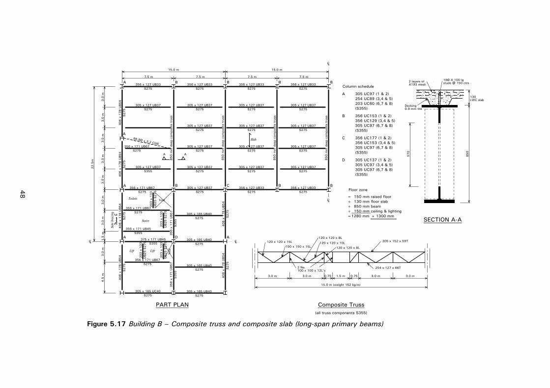
P137v0
2d1
0.doc
48
Printed 0
8/1
1/0
4
Column schedule
A
B
305 UC97 (1 & 2)254 UC89 (3,4 & 5)203 UC60 (6,7 & 8)
356 UC153 (1 & 2)356 UC129 (3,4 & 5)305 UC97 (6,7 & 8)
C
305 UC97 (6,7 & 8)
356 UC177 (1 & 2)356 UC153 (3,4 & 5)
D305 UC97 (3,4 & 5)305 UC97 (6,7 & 8)
Floor zone
305 UC137 (1 & 2)
SECTION A-A
+ 130 mm floor slab= 150 mm raised floor
(S355)
(S355)
(S355)
(S355)
CL
CL
A
A A
CL
15.0 m15.0 m
22.5
m
3.0
m3.0
m3.0
m1.5
m4.5
m
203 x
133
203 x
133
203 x
133
Side
bra
cing
Toilets
Stairs
Void
Lift Lift
Voi
d
D
PART PLAN
203 x
133
UB25 S
275
UB25 S
275
UB25 S
275
UB25 S
275
356 x 171 UB67S275
7.5 m7.5 m7.5 m7.5 m
A
A
375 x 171 UB45S355
CL
B
B
BBB
BC
305 x 165 UB40S275
305 x 165 UB40S275
305 x 165 UB40S275
305 x 165 UB40S275
B
356 x
171 U
B57
S355
356 x
171 U
B57
S355
305 x 127 UB37S355
A A
3.0
m3.0
m3.0
m3.0
m3.0
m
Composite Truss
3.0 m 3.0 m 3.0 m 3.0 m1.5 m 0.750.75
120 x 120 x 15L
2 No.100 x 100 x 12L's
305 x 152 x 59T
254 x 127 x 66T
150 x 150 x 15L
120 x 120 x 8L
120 x 120 x 10L
120 x 120 x 8L
+ 850 mm beam
19Ø X 100 lg studs @ 150 ctrs
850
130LWC slab
570
356 x 127 UB33S275
356 x 127 UB33S275
356 x 127 UB33S275
356 x 127 UB33S275
356 x 127 UB33S275
356 x 127 UB33S275
305 x 127 UB37S275
305 x 127 UB37S275
305 x 127 UB37S275
305 x 127 UB37S275
305 x 127 UB37S275
305 x 127 UB37S275
305 x 127 UB37S275
305 x 127 UB37S275
305 x 127 UB37S275
305 x 127 UB37S275
305 x 127 UB37S275
305 x 127 UB37S275
305 x 127 UB37S275
305 x 127 UB37S275
850 m
m d
eep
com
posi
te t
russ
850 m
m d
eep
com
posi
te t
russ
850 m
m d
eep
com
posi
te t
russ
850 m
m d
eep
com
posi
te t
russ
356 x 171 UB67S275
88.9Ø x 3.2 CHS
406 x
178 U
B54
S275
406 x
178 U
B54
S275
406 x
178 U
B54
S275
406 x
178 U
B54
S275
406 x
178 U
B54
S275
406 x
178 U
B54
S275
356 x 171 UB67S275
356 x 171 UB45S355
305 x 165 UC40S275
15.0 m (weight 162 kg/m)
≈=1280 mm 1300 mm
356 x 171 UB67S275
Slab
+ 150 mm ceiling & lighting
2 layers ofA193 mesh
Decking 0.9 mm thk
(all truss components S355)
Figure 5.17 Building B – Composite truss and composite slab (long-span primary beams)

P137v0
2d1
0.doc
49
Printed 0
8/1
1/0
4
Stairs
Void
Lift & ServiceVoids
Part Plan
A A
LC
LC300 thk slab
7.5 m 7.5 m 7.5 m 7.5 m
7.5 m
7.5 m
3.0 m
3.0 m
3.0 m
1.5 m
4.5 m
300 thk. R.C.core wall
600 x 600column
800 x 300edge column
300
22.5 m
30.0 m
Floor zone= 150 mm raised floor+ 300 mm concrete slab+ 400 mm Fan Coil Units/ducts + 150 mm ceiling & lighting 1000 mm
SECTION A - A
PART PLAN
Figure 5.18 Building B – Reinforced concrete flat slab

P137v0
2d1
0.doc
50
Printed 0
8/1
1/0
4
Column schedule
B
6.0
m6.0
m
CL
15.0 m
7.5 m7.5 m7.5 m7.5 m
B
PART PLAN
CL
9.0
m9.0
m1.7
m
22.7
mA
A
A B B
B B
B
B
Void
Stairs
A
BA B
CL
15.0 m
Lifts
CL
A 500 Ø
B 600 Ø
500 x
500 r
ib
150 s
lab
A
250300
275275
750 x 500 deep beam
250 x 500 deep edge beam
250 x 500 deep edge beam
750x 500 deep beam
550 x
500 d
eep
edge
bea
m
Void
A
550 x
500 d
eep
edge
bea
m
1.7
m
T8 - 300
4 x T16
4 x T254 No 12.9 mm dia.Tendons
DETAIL 1
500
550
150
25002500 2500
500
SECTION A - A
Detail 1Floor zone
= 150 mm raised floor
+ 150 mm ceiling & lighting=1200 mm
+ 400 mm services+ 500 mm beam and slab
Figure 5.19 Building B – Post-tensioned ribbed slab (with modified column positions)

P137v02d10.doc 51 Printed 08/11/04
6 DESIGN OF NON-FRAME COMPONENTS
The following aspects of the design of the non-structural components are reviewed, as they have an influence on the relative economy of the different structural options.
6.1 Fire protection Fire resistance is normally achieved by applying fire protection materials to the steelwork. The required thickness of fire protection applied to the members is a function of the:
• Fire resistance period.
• Section factor of the member (exposed perimeter/cross-sectional area).
• Type of fire protection.
• Loading conditions and utilisation factors in the design of the member.
Thicknesses for fire protection may be obtained from the ASFP/SCI publication Fire protection for structural steel in buildings[29]. This publication follows the principles for fire resistant design given in BS 5950-8:2002[30].
For this study, the columns in both Building A and Building B are protected using a board system to create a rectangular profile. Board protection is also used for the beams and bracing members in Building A. In Building B, the floor beams are protected using an on-site applied intumescent coating, except for the cellular (primary) beam option. In this scheme, the cellular beam is fabricated from plates and the thickness of intumescent coating is optimised and is applied as a single layer in an off-site process. This can lead to a saving in construction time on-site.
Cementitious spray protection is provided for the composite truss, although it is recognised that the popularity of cementitious sprayed protection has diminished because of the disruption that the relatively messy operation can cause to internal finishes and to cladding installation.
The rationalisation of board protection systems is limited by the thicknesses of the boards that are manufactured. Therefore, the thicknesses are considered in increments (typically 5 mm for boards). Thicknesses of 15 to 25 mm are typical for 60 minutes fire resistance (Building A) and 20 to 25 mm for 90 minutes fire resistance (Building B).
ASB(FE) sections in Slimdek® do not require fire protection for 60 minutes fire resistance because of the partial concrete encasement, but they are provided with an on-site intumescent coating protection to the soffit for 90 minutes fire resistance.
Where I-section edge beams are used in Slimflor®/Slimdek® schemes and they can be contained within the floor construction depth, it makes sense to maintain the uninterrupted soffit line, and so partially encase the beam in the slab on one

P137v02d10.doc 52 Printed 08/11/04
side. For this specific case, no additional board protection has been provided for 60 minutes resistance, but an intumescent coating is provided to the bottom flange and external face for 90 minutes fire resistance required in Building B. Where RHS Slimflor® edge beams are used in Building B, they are provided with an intumescent coating on the underside and external face.
Some relaxation in the fire resistance may be possible if a fire engineering approach is used, based on the results of the fire tests at BRE Cardington[31]. A relaxation would also be possible if the building is protected by sprinklers.
The costs in the study do not include those for fire-resisting glazing to the atrium walls in Building B. Using a fire safety engineering approach may provide alternative solutions for the fire design of the atrium. The detailed approach would include consideration of means of escape and use of sprinklers, etc. In developing a fire safety strategy for the building, this could result in cost savings in fire protection measures.
6.2 Cladding The brick external cladding for Building A is supported on stainless steel support angles attached to the side of the slab or the edge beam. The blockwork is placed directly on the slab. In order to provide lateral support to the perforated walls, two wind posts are used in the 7.5 m wide panels and one in the 6 m wide panels. The wind posts are attached to the top and underside of the slab or edge beams. The following additional allowances are made for these components:
Brick support: 125×110×8 mm (14.8 kg/m) stainless steel angle
Wind posts: 100×60×5 mm (11.7 kg/m) Rectangular Hollow Section (RHS)
Both these quantities are included in the weight of ‘additional steelwork’ in Table 5.1.
The highly glazed façade system in Building B is assumed to be designed by a specialist sub-contractor. Stricter deflection limits are introduced for the edge beams in order to prevent damage to the glazing.
In both cases the depth of construction, and hence the floor-to-floor height, influences the cost of the cladding. This is particularly important for Building B.
6.3 Foundations The foundation material for Building A is considered to be sand, with a safe bearing pressure of 200 kN/m2. The depth and width of the footing, and the amount of reinforcement can be determined from the column loads.
The foundations for Building B are in stiff over-consolidated clay, with an undrained shear strength of Cu = 70+7z, where z is the depth into the clay. This material is considered suitable for piles, but not for footings. Single large diameter under-reamed piles are used, rather than multiple small-diameter piles. The pile capacity is achieved partly by end bearing and partly by skin friction. All piles are assumed to be founded at 14 m below ground level and their

P137v02d10.doc 53 Printed 08/11/04
diameter is varied to suit the applied loads. The piles are reinforced to approximately 0.3% of their cross-section area.
The comparative foundation loads are given in Table 6.1, which reflects the different self-weight of the various options. The schedule of pad footing and pile sizes for the two buildings is presented in Table 6.2 and Table 6.3. The variable cost of the footings also includes the excavation and formwork.
The ground floor slab is a reinforced concrete slab of 150 mm thickness with a thickening at internal core walls and at the edges. The slab is supported on a granular fill, and is waterproofed by ‘bituthene’ or an equivalent layer directly underneath. Additional reinforced concrete construction is provided for the lift recesses and basement areas. A general allowance is made for these items, which are common to all structural options.
Table 6.1 Summary of approximate characteristic column loads (in kN) at ground level for Buildings A and B
Building A Building B Form of Construction
External Internal External Internal
Slim floor – p.c. slabs 1120 1480 3600 5610
Slimdek® 1120 1480 2300* 3500*
Composite beams and slab 1050 1350 2650 3800
R.C. flat slab 1420 2250 3500 6400
Long-span composite beams 1600 – 4620 –
P.C. concrete beams 2850 – 6500 –
Post-tensioned ribbed slab – – 5500 –
*based on 6 × 7.5 grid
Table 6.2 Summary of approximate pad footing sizes for Building A
Form of Construction
Internal Column (m)
External Column (m)
Corner Column (m)
Slim floor – p.c. slabs
2.7 × 2.7 × 1.1 2.4 × 2.4 × 1.0 1.9 × 1.9 × 1.0
Slimdek® 2.7 × 2.7 × 1.1 2.4 × 2.4 × 1.0 1.9 × 1.9 × 1.0
Composite beams and slab
2.6 × 2.6 × 1.0 2.3 × 2.3 × 1.0 1.9 × 1.9 × 1.0
R.C. flat slab 3.5 × 3.5 × 1.4 3.0 × 2.6 × 1.2 2.3 × 2.3 × 1.0
Long-span composite slabs
– 2.9 × 2.9 × 1.1 1.7 × 1.7 × 1.0
P.C. concrete beams
– 3.8 × 3.8 × 1.3 2.3 × 2.3 × 1.1
N.B. Reinforcement is based on 30 kg/m2 of footing area. A 2.0 m wide × 1.5 m deep strip footing is provided for the shear walls in the concrete schemes. Pad sizes are based on column loads in Table 6.1 and 200 kN/m2 bearing pressure.

P137v02d10.doc 54 Printed 08/11/04
Table 6.3 Summary of approximate pile sizes for Building B
Pile Type 1 Pile Type 2 Form of Construction
No. Shaft diameter
(m)
Under-ream
diameter (m)
No. Shaft diameter
(m)
Under-ream
diameter (m)
Slim floor – p.c. slabs
24 1.05 2.75 32 0.75 2.0
Slimdek® 24 0.9 2.0 32 0.75 2.0
Composite beams and slab
24 0.9 2.0 32 0.75 2.0
R.C. flat slab 24 1.05 3.0 32 0.9 2.5
Post-tensioned ribbed slab
28 1.2 3.6 12 1.05 2.4
Long-span composite beams
6 1.05 2.5 36 0.75 2.5
Pre-cast double T beam
10 1.2 3.0 32 1.2 3.0
N.B. Piles are assumed to be founded at 14 m below ground level. Reinforcement is based on 25 kg/m3 concrete volume. Smaller piles are used beneath core areas.
6.4 Mechanical services Mechanical services for air-conditioning are provided only in Building B and have not been designed in detail, but the different schemes offer varying degrees of ease of installation of services. Clearly, an uninterrupted flat soffit will enable horizontal services to be distributed more easily than in some of the schemes with downstand beams.
The space requirements, and hence the floor zone height, are presented in Section 4.3. An objective view has been taken in the costs as to how easily these services can be installed. Circular ducts can be more cost-effective than rectangular ducts, although rectangular ducts are often used to minimise the depth below downstand beams. The use of circular ducts proved to be cost effective for the cellular beam scheme. In the Slimdek® schemes, partial integration of the fan-coil units and smaller pipes is considered.
6.5 Other common items The ground floor slab is a reinforced concrete slab of 150 mm thickness. It is water proofed by ‘bituthene’ or an equivalent layer beneath the slab, which is directly supported on a granular fill. Additional reinforced concrete construction is provided for the lift recesses and basement areas. A general allowance is made for these items, which are common to all structural options.

P137v02d10.doc 55 Printed 08/11/04
7 CONSTRUCTION PROGRAMMING
7.1 Common assumptions In determining the construction programmes for the two building forms, the following common assumptions have been made:
• The basis of programming and plant resources of each option is consistent, so as not to favour any form of structure.
• Key interfaces with preceding and following trades have been maintained. Important milestones are indicated.
• All trade items and sequences are common for all options.
• Pre-ordering of plant (including lifts) and cladding is critical to the construction programmes.
• Decking and shear stud teams are resourced to achieve the same erection cycle as for the steel frames. Fixing of edge trims and openings is included in the cycle.
• A concrete pump is used for in-situ concrete.
• The steel columns are erected in 2-storey lengths.
• Pre-cast stairs are included in all options.
• Programmes for all options include for normal Q.A. checks.
7.2 Additional assumptions for Building A Additional assumptions particular to the construction programme for Building A are as follows:
• The frame and precast slabs are erected by one mobile crane.
• The in-situ concrete options involve completion of the ground floor slab first, whereas the steel frame options do not.
• The roof plant rooms are common to all schemes. Plant is lifted by mobile crane once the structure is complete.
7.3 Additional assumptions for Building B Additional assumptions particular to the construction programme for Building B are as follows:
• Two tower cranes are installed at opposite ends of the building.
• For all options it is assumed that the basement is constructed first, followed by completion of the ground floor slab.
• RC flat slab and post-tensioned ribbed slab options use table-forms and prefabricated formers.
• Plant items are lifted by tower crane.
• Glazing units are lifted by tower crane, and are not installed until major works are completed above, for safety reasons.

P137v02d10.doc 56 Printed 08/11/04
7.4 Construction rates The following rates of principal construction activities were adopted as being realistic for the building schemes considered.
Steel erection (per gang):
• Columns 25 lengths per day
• Beams 45 per day
• Bracings 30 members per day
Decking placement:
• Sheets (6 m × 0.9 m) 40 per day
Shear studs:
• Through-deck welding 50 per 2 man team per day
Pre-cast concrete units or beams:
• 6 m long 35-40 per day
• 10 m + long 20-30 per day
In-situ pumped concrete (per gang):
• On steel decking 1000 m2 per day
• On other formwork 250 m2 per day
Fire protection to steel members (per man):
• Board 30 m2 per day
• Cementitious spray (20 mm thick) 40 m2 per day
• Intumescent coating (sprayed on-site) 0.75 to 1.5 lin metres/hour/coat
Formwork tables 500 to 750 m2 per day Reinforcement fixing 0.3 to 0.7 t per 4 man gang /day
7.5 Construction programmes – Building A The construction programmes for the various options are summarised in Table 7.1, and they are presented in graphical form in Figure A.1 in Appendix A. Detailed programmes for the Slimdek® and reinforced concrete slab schemes are also provided in this Appendix.
Table 7.1 shows that the overall construction times on site for the steel schemes and for the concrete schemes are similar, at between 40 and 43 weeks. The scheme with the shortest construction time is that using Slimdek® (unpropped), at 40 weeks. There is a difference between the procurement times for the steel scheme (20-21 weeks) and the concrete scheme (10-12 weeks). The frame construction times are relatively short: 8 weeks for the concrete options and between 6 and 8 weeks for the steel options. All concrete frame options begin 2 weeks later than the steel options, owing to the need to construct the ground bearing slab first.

P137v02d10.doc 57 Printed 08/11/04
7.6 Construction programmes – Building B The overall construction programmes are summarised in Table 7.1, and are also shown graphically in Figure A.2 in Appendix A. Detailed programmes for the cellular beam (primary beams fabricated from plates) scheme and the post-tensioned ribbed slab scheme are also provided in this Appendix.
The overall construction time on site for the steel schemes are similar, at 66 or 67 weeks. The construction time on site for the concrete options are longer, at 76 weeks. The time for the erection of the frame ranges from 13 weeks in the steel options to 19 weeks in the reinforced concrete options. The long-span steel options may be slightly faster to construct because of the reduced piece-count and, hence, the lower use of crane hook time than the short-span options. There is also a difference between the procurement times for the steel schemes (18 weeks) and the concrete schemes (7 weeks). The construction of the basement areas is considered to take 4 weeks, assuming that the excavation can be made without major temporary works.
The non-frame items are broadly similar for all options.
Table 7.1 Construction times for the various options
Structural Form
Building A
Procurement time
(Weeks)
Overall construction time on site
(Weeks)
Frame construction
time (Weeks)
Slimflor® + precast slabs 20 42 7
Slimdek® (deep deck (propped)) 21 42 7
Slimdek® (deep deck (unpropped)) 21 40 6
Composite beams + composite slabs 20 42 7
Composite beams with web openings 21 41 6
Cellular beams + composite slabs (with on-site intumescent coating)
21 41 6
Reinforced concrete flat slabs 10 43 8
Precast concrete – hollow core units 12 43 8
Precast – double tee units 12 43 8
Building B
Slimdek® (deep deck (unpropped)) 18 67 13
Slimdek® (deep deck (propped)) 18 67 13
Composite beams + composite slabs 18 67 13
Cellular secondary beams +composite slabs (with on-site intumescent coating)
18 66 13
Fabricated cellular primary beams + composite slab (with off-site intumescent coating)
18 66 13
Tapered fabricated girder 18 66 13
Haunched composite beams 18 66 13
Composite trusses 18 66 13
Reinforced concrete flat slabs 7 76 18
Post-tensioned ribbed slab 7 76 19
Note: Basement construction is assumed to add 4 weeks to the construction times given for Building B.

P137v02d10.doc 58 Printed 08/11/04
8 BUILDING COSTS
8.1 Introduction Making general cost comparisons of different structural systems is notoriously difficult, because of the large number of factors that have to be taken into account. Whilst the buildings that have been used in the study are intended to be representative of current commercial building designs, they have been selected primarily to draw out the differences among the structural systems. Any particular development will ultimately require its own cost appraisal.
The study is based on the most efficient design for each of the structural forms included. The regular shape of the buildings means that costs have been optimised. As such, the final costs shown may be slightly less than those experienced on actual completed buildings, which tend to have various complexities (leading to higher costs). Nevertheless, the comparisons between the options should remain valid.
The study considers the differences in the labour and material content of the various options, the different floor-to-floor heights and their effect on the cost of the vertical elements, plus the differences arising from variation in the speed of construction. In addition, it should be recognised that there are non-quantified benefits that add value to the building in some of the systems in terms of:
• Increased column-free space, which provides flexibility in terms of use and space planning.
• Ease of future adaptation and change of use.
• Less disruption during the construction process.
The methodology of the previous study[2] has been maintained. Each of the structural options has been considered in detail in the context of the designs for Buildings A and B. Measured quantities have been prepared and provided on an itemised basis for the foundations, frame and upper floors. Unit quantities have been prepared for all other elements and priced by applying composite unit rates that cover labour, plant and materials. The cost of preliminaries has been assessed and shown separately.
8.2 General basis of pricing Wherever possible, the tender prices used to compile the study have been extracted from actual projects that have been competitively tendered but, where necessary, prices have also been obtained from specialist sub-contractors and suppliers. The price levels reflect those prevailing in the last quarter of the calendar year 2003. A schedule of the key rates used for the structural frame and floors in the study is provided in Table 8.2.
Building A is representative of a speculative office building in a regional city in the UK, and has been priced in Greater Manchester. Building B is representative of a prestige building in London, and has been priced as central London. The design and price level of both buildings represent typical developer’s standard specifications for the building type and locality.

P137v02d10.doc 59 Printed 19/11/04
The results can be adjusted using the regional variation factors shown in Section 8.4.
8.3 Market conditions The UK construction industry has experienced unprecedented market conditions after the recession of the early 1990’s. Between 1992 (the date of prices for the previous study) and 2003, tender prices have risen steadily above inflation, leading to a cumulative increase of costs of over 80% (on average). However, over this period, differing regional market conditions have seen prices rise by 95% in the South East and 75% in the North.
During periods of high activity, premiums are paid to secure materials/components in short supply and rates above the nationally agreed wage norm are required to attract labour. There is now a strong incentive to manufacture off-site in factory conditions in locations of skilled labour. The Egan Report Re-thinking Construction[1] called for a radical re-examination of construction processes and procurement.
Steel sub-contractors have benefited from buoyant market conditions in the commercial sector over most of this period but steelwork price rises have, until recently, been very restrained compared to most trades. Competition amongst fabricators and sub-contractors remains keen and price rises of erected steelwork have been limited to about 35% since 1992 and 15% since 1994. By comparison, prices for in situ concrete have risen by about 70% (partly influenced by the effects of the Aggregates Levy[32], introduced by the Government on 1st April 2002) and prices for brickwork and blockwork by about 80% (largely due to labour shortages). With formwork prices rising even more (owing to a shortage of formwork carpenters) and reinforcement prices rising substantially, it is not surprising that the study has shown an increased difference between the costs of reinforced concrete schemes and steel schemes since 1992.
Overall, costs have also been influenced by an increase in the cost of main contractors’ site management and overheads, which have risen steadily from 7.5%, at a low level in 1992, to an average of 14% in 2003. The effect of recent price rises in cost of materials is presented in Appendix B.
8.4 Regional variations The cost comparisons presented in this study reflect price levels in Manchester for Building A, and central London for Building B. Table 8.1 provides adjustment factors that may be applied to provide indicative costs for each of the building types, built within another region.

P137v02d10.doc 60 Printed 19/11/04
Table 8.1 Regional adjustments to total building cost
Adjustment to cost tables %
Building A Building B
Outer London + 16 – 7
Central London + 23 0
East Anglia – 4 – 16
East Midlands – 1 – 19
North East – 2 – 20
North West 0 - 19
Northern Ireland -15 -30
Scotland – 1 – 20
South East + 11 – 11
South West 0 – 19
Wales – 1 – 20
West Midlands 0 – 19
Yorkshire and Humberside – 4 – 22
8.5 Preliminaries Generally, the cost of the main contractor’s preliminaries, comprising site management and on-site facilities, have been assessed at 13% for Building A and 15% for Building B, the higher figure for Building B representing additional plant costs and the higher costs of working in central London. However, these figures have been adjusted for time-related items that will be affected by the different construction periods of each option.
8.6 Time-related savings Savings relating to the speed of construction may be quantified by the three factors given below:
8.6.1 Reduced cost of preliminaries The majority of the main contractor’s preliminaries are time-related and will be affected by the contract period. Therefore, an adjustment has been made for the steel options using the reinforced concrete flat slab as a baseline. It has been assumed that 85% of the preliminaries cost is time-related.
8.6.2 Reduced cost of borrowing Finance costs can be significant, particularly when development is undertaken using borrowed money. Even when schemes are self-financed, there is still an ‘opportunity cost’ of not investing the outlay for the building. The finance costs will be affected by the prevailing interest rate and the period the money needs to be borrowed, which is, in turn, affected by the speed of construction. For comparative purposes, finance costs have been taken as 6% based on representative cost of borrowing, and reductions have been made to the finance costs for each scheme according to how short its contract period is in relation to the scheme with the longest construction period (normally RC flat slab).

P137v02d10.doc 61 Printed 19/11/04
8.6.3 Early rental Provided a tenant can be found promptly, the early completion of a building would advance the return in terms of rental income, so offsetting the cost of borrowing; and possibly leading to an early sale of the building. However, for the purposes of this study, return on early rental is not included because an increasing number of developments are now only undertaken once a ‘pre-let’ has been established, and only the benefits arising from reduced borrowing have been considered.
8.7 Steel construction The key rates for the structural steelwork used in the steel schemes are given in Table 8.2, and rates for the fire protection and other structural items in the floors are given in Table 8.3. The majority of the rates have been derived from recently tendered projects, and reflect the current active market conditions. Clearly, these rates for steel fabrication are subject to fluctuation, depending on the complexity of the project and the prevailing market for steel fabrication and construction. The different steel options utilise members with varying degrees of complexity of fabrication, which is reflected in the rates applied in this study.
The rates for steel fabrication include design, connections, transport and erection, but assume that the steel is not painted. The rates used for the various steel options were obtained on the basis of recently tendered projects or discussions with steel fabricators, where relevant.
The rates applied to the other steel-related components (fire protection, steel decking, etc) have also been derived from recently tendered projects. When applying the rates for the fire protection, adjustments have been made to take account of the complexity involved in certain steel options.
Table 8.2 Schedule of key rates for structural steelwork
Item Unit Building A rate Building B rate
Structural Steelwork
Universal beams (S275) Tonne £950 £1,030
Universal beams (S355) Tonne £1,000 £1,100
Universal columns (S355) Tonne £975 £1,050
Cellular beams Tonne £1,300 £1,400
Tapered girders (S355) Tonne – £1,550
Haunched beams (S355) Tonne – £1,600
Composite truss (S355) Tonne – £1,400
Composite beam with openings (S355) Tonne £1,500 –
Asymmetric Slimflor® beams (S355) Tonne £1,075 £1,120
Ties; ‘T’ sections (S275) Tonne £1,000 £1,100
Beam flange plates 15 mm thick (S355) Tonne £1,250 £1,400
Wall bracing; flat (S275) Tonne £1,050 –
Wall bracing; tubular (S275) Tonne £1,550 –
Wall bracing; tubular (S355) Tonne – £1,650
Wind posts; tubular (S275) Tonne £1,250 –
NB: Rates based on fourth quarter 2003 Rates for Building A assume construction in the North West region of the UK (Manchester) Rates for Building B assume construction in central London

P137v02d10.doc 62 Printed 08/11/04
Table 8.3 Schedule of key rates for the fire protection and other items for the structural steel frame and floors
Item Unit Building A rate Building B rate
Fire protection:
Resin-bonded rock fibre board m2 £9.50 -
Glass fibre reinforced gypsum board m2 £16.00 £20.00
Cement-based vermiculite spray m2 - £12.70
Intumescent coating for 60 mins fire resistance (on-site)
m2 £10.50 -
Intumescent coating for 90 mins fire resistance (on-site)
m2 - £23.00
Intumescent coating for 90 mins fire resistance (off-site)
m2 - £32.00
Other structural items for steel framed options:
19 mm diameter × 100 mm long shear studs
Each £1.30 £1.40
A142 mesh reinforcement m2 £2.00 -
A193 mesh reinforcement m2 £2.50 £3.00
Normal weight concrete slab – pumped m2 £97.00 £115.00
Light weight concrete slab – pumped m2 - £130.00
Shallow profiled steel decking 0.9 mm thick
m2 £12.00 -
Shallow profiled steel decking 1.2 mm thick
m2 - £13.50
SD225 steel deep decking (unpropped) m2 £26.00 £25.00
SD225 steel deep decking (propped) m2 £29.00 £29.00
Reinforcement bar (T12) Tonne - £760.00
Reinforcement bar (T16) Tonne £575.00 £730.00
Reinforcement bar (T20) Tonne £550.00 £700.00
NB: Rates based on fourth quarter 2003 Rates for Building A assume construction in the North West region of the UK (Manchester) Rates for Building B assume construction in central London
8.8 Concrete construction The key rates for the structural components used in the concrete schemes are included in Table 8.4. The itemised rates for the various concrete components, including foundations, ground floor, basement, upper floor and roof, have been compiled from recently tendered projects. The rates for the associated work items (excavation, reinforcement, formwork, etc) have been derived similarly from recently tendered projects and published sources.

P137v02d10.doc 63 Printed 08/11/04
Table 8.4 Schedule of key rates for the structural frame and floors for the concrete schemes
Item Unit Building A rate Building B rate
Concrete floor slabs
Reinforced concrete flat slab – 300 mm thick
m2 £81.20 £100.00
Attached reinforced concrete beams 200 × 400 mm
m £48.80 £70.20
Isolated reinforced concrete edge beams 500 × 825 mm
m £165.60 -
Isolated reinforced concrete cranked beam 200 × 500 mm
m £75.10 -
Reinforced post-tensioned concrete slab 150 mm thick
m2 - £125.30
Attached reinforced concrete beams 500 × 250 mm
m - £70.00
Attached reinforced concrete beams 500 × 500 mm
m - £160.00
Attached reinforced concrete beams 750 × 500 mm
m - £230.00
Reinforcement interface between slabs and columns
Each £240.00 £310.00
Precast concrete floor units
Precast double tee unit 1200 mm wide × 500 mm deep
m2 £69.00 -
Precast concrete floor slabs 200 mm thick
m2 £36.00 -
Precast concrete floor slabs 400 mm thick
m2 £51.00 -
Concrete columns and walls
400 × 400 mm, reinforcement – 270 kg/m3
m £91.30 -
600 × 300 mm, reinforcement – 245 kg/m3
m £90.80 -
800 × 300 mm, reinforcement – 170 kg/m3
m - £141.00
450 × 450 mm, reinforcement – 280 kg/m3
m - £154.00
525 × 525 mm, reinforcement – 190 kg/m3
m - £192.00
Reinforced concrete shear wall - 250 mm thick
m2 £99.10 -
Reinforced concrete shear wall - 300 mm thick
m2 - £137.00
NB: Rates based on fourth quarter 2003 Rates for Building A assume construction in the North West region of the UK (Manchester) Rates for Building B assume construction in central London

P137v02d10.doc 64 Printed 08/11/04
8.9 Other elements The composite unit rates used for the other elements have been compiled from Davis Langdon’s cost database. These are based on the specification and details stated earlier in Section 3, and reflect a typical developer’s standard of specification.
A contingency and design reserve of 7.5% has also been added in order to reflect the typical level of total cost for the generic offices represented by Buildings A and B.
A base mechanical services cost of £229/m2 was assumed for a building of this configuration, based on a Fan Coil air-water system. This cost also includes the apportioned cost of the central plant, which is about 40% of the total.
The cost of the air distribution system in Building B is affected by the complexity of the integration of the structure and services. Various factors have been applied to the base costs of the mechanical services in the schemes.
These differences are affected by the shape of the ducts (circular ducts being cheaper and more efficient than rectangular ducts) and by the total length of the ducts. Circular ducts could have been used in more of the systems, but floor depth would have increased. Hence, there is a ‘trade-off’ between services and cladding cost.
No allowance has been made for external works, drainage and external services, and non-construction costs, such as furniture, equipment, professional fees and VAT.
8.10 Elemental breakdown of costs The elemental costs have been calculated for each of the structural options for Building A and Building B, and these are presented in Table 8.5 and Table 8.6. A summation of the elemental costs, including preliminaries and contingency, provides the total cost. The net cost is then deduced by including the time-related saving in finance cost, using the slowest option as a ‘benchmark’ datum.
The main variable elements are the:
• Sub-structure.
• Upper floors and frame.
• External walls.
• Internal walls.
• Mechanical services (in Building B).
• Preliminaries and contingency.
The remaining items are effectively constant for all the options.
8.11 Comparison of building costs Comparisons of total and net costs are presented graphically in Figure 8.1 and Figure 8.2. All costs are per square metre of gross floor area, at price levels

P137v02d10.doc 65 Printed 19/11/04
current in the last quarter of 2003, and exclude the cost of external works, professional fees and VAT. The comparison of costs is also given in tabular form in Table 8.7. In that table, the cost of the structure is presented, which is defined as that for the frame and upper floors (excluding the roof, stairs, foundations and walls). The structure cost and the total cost do not include the time-related adjustment. Indices are given for the total and for the net costs, using a value of 100 for the cheapest option in each case.
8.11.1 Summary of costs for Building A For Building A, the cheapest option is the composite beam and slab scheme. The next cheapest are the Slimdek® schemes, which are similar in price and only 1% more expensive. The cheapest long-span option, which is the cellular beams (long-span secondary beams) with a composite slab, is just over 3% more expensive than the cheapest short-span scheme. The three concrete frame options are the most expensive, at about 5 to 7.4% more expensive than the composite beam and slab scheme.
The cost of the structure only for Building A varies between £71 per m2 (composite beam and slab) and £122 per m2 (in-situ frame with precast double Tee units) and represents between 7.7% and 12.2% of the total building cost, including preliminaries and contingencies.
As noted in Section 7.5, the construction period for the various options in Building A varies only between 40 weeks (Slimdek® unpropped) and 43/44 weeks (reinforced concrete schemes). Consequently, time-related savings are relatively small. The net building costs differ only slightly from the total building costs, as the similarity between the indices shows, but the steel options gain relative to the concrete options.
8.11.2 Summary of costs for Building B For Building B, the cheapest cost in terms of structure only is the composite beam and slab scheme, but the reduced floor-to-floor height enables the Slimdek® (unpropped) scheme to achieve the lowest total building cost. However, for 7 out of the 10 schemes, the total cost does not exceed the lowest by more than 2%, which indicates that they have similar economic merit. Only the composite truss scheme (+5.4%) and the reinforced concrete slab schemes (+6.7% and +6.8%) are significantly higher in total cost than the unpropped Slimdek® scheme. The cheapest long-span option is the cellular (secondary) beam, which is just 1.2% more expensive than the cheapest short-span scheme.
In terms of the cost of the structure only, the 8 steel schemes vary between £83 and £108 per m2, which is between 5.4% and 7% of the total building cost (including preliminaries and contingencies). By contrast, the costs of the structure for the concrete schemes are £144 m2 (reinforced concrete flat slab) and £170 per m2 (post-tensioned ribbed slab), which are 8.8% and 10.4% of the total building cost.
The margin between the cost of the reinforced concrete scheme and the steel schemes in Building B widens further once the time-related preliminaries and ‘extra (saving) in finance costs’ are taken into account. As noted in Section 7.6, the construction period for the steel schemes varies only between 66 and 67 weeks, but the reinforced concrete schemes require a 76 and 77 weeks’ construction period. This is reflected in the divergence of the total and net cost indices for the concrete schemes.

Table 8.5 Elemental cost per m2 of gross internal floor area for Building A
Description Slimflor® Beams + Precast
Slabs with downstand edge beams
Slimdek® (ASB, Deep
Deck (Propped))
with downstand edge beams
Slimdek® (ASB, Deep
Deck (Unpropped))
with integral edge
beams
Composite Beams + Composite
Slab
Long-span Composite Beams with
Web Openings
Cellular Beams + Composite Slab (with
on-site intumescent
coatings)
Reinforced Concrete Flat Slab
Insitu Concrete
Frame with Precast
Concrete floor (hollow core) units
Insitu Concrete
Frame with Precast
Concrete (double tee)
units
£/m2 £/m2 £/m2 £/m2 £/m2 £/m2 £/m2 £/m2 £/m2
1. Substructure 27 26 26 25 26 26 37 34 34
2. Upper floors and frame 90 86 90 71 96 91 118 101 120
3. Pitched roof 20 20 20 20 20 20 20 20 20
4. Stairs 17 18 18 19 20 20 18 19 19
5. External walls 64 67 67 70 76 77 67 71 73
6. Window and external doors 99 99 99 99 99 99 99 99 99
7. Internal walls, partitions and doors 32 32 32 33 34 35 32 33 33
8. Wall finishes 16 16 16 16 16 16 16 16 16
9. Floor finishes 63 63 63 63 63 63 63 63 63
10. Ceiling finishes 25 25 25 25 25 25 25 25 25
11. Fittings 10 10 10 10 10 10 10 10 10
12. Sanitary fittings and disposal 44 44 44 44 44 44 44 44 44
13. Mechanical services 97 97 97 97 97 97 97 97 97
14. Electrical services 85 85 85 85 85 85 85 85 85
15. Lift installation 42 42 42 42 42 42 42 42 42
16. Builders work – services 33 33 33 33 33 33 33 33 33
Sub Total 764 761 765 751 785 782 804 791 812
17. Preliminaries (13%) 103 103 99 103 101 101 107 105 105
Sub Total 867 864 864 854 886 883 911 896 917
18. Contingency (7.5%) 65 64 64 64 66 66 68 67 68
19. Total building cost per m2 of gfa 932 928 928 918 952 949 979 963 985
A. Construction period in weeks 42 42 40 42 41 41 44 43 43
B. Extra (saving) in finance costs @ 6% p.a. -2 -2 -3 -2 -2 -2 0 -1 -1
C. Net building cost per m2 of gfa 930 926 925 916 950 947 979 962 984
66

Table 8.6 Elemental cost per m2 of gross internal floor area for Building B
Description Slimdek® (ASB, deep
deck (unpropped))
with downstand edge beams
Slimdek® (ASB, deep
deck (propped)) with RHS Slimflor®
edge beams
Composite Beams + Composite
Slab
Cellular (secondary) Beams (with
on-site intumescent
coatings)
Fabricated Cellular
(primary) Beams (with
off-site intumescent
coatings)
Tapered Fabricated
Girder (primary beams)
Haunched Composite
Beams
Composite Trusses (primary beams)
Reinforced Concrete Flat Slab
Post-Tensioned Ribbed slab
£/m2 £/m2 £/m2 £/m2 £/m2 £/m2 £/m2 £/m2 £/m2 £/m2
1. Substructure 40 41 41 37 37 37 37 37 48 48
2. Upper floors and frame 100 108 83 105 103 104 101 106 144 170
3. Roof 34 34 34 34 34 34 34 34 34 34
4. Stairs 24 24 25 25 25 25 25 26 25 24
5. External walls 295 295 310 303 310 310 314 343 310 288
6. Window and external doors 4 4 4 4 4 4 4 4 4 4
7. Internal walls, partitions and doors 92 92 95 95 95 95 95 109 92 88
8. Wall finishes 16 16 16 16 16 16 16 16 16 16
9. Floor finishes 85 85 85 85 85 85 85 85 85 85
10. Ceiling finishes 46 46 46 46 46 46 46 46 46 46
11. Fittings 4 4 4 4 4 4 4 4 4 4
12. Sanitary fittings and disposal 46 46 46 46 46 46 46 46 46 46
13. Mechanical services 229 229 231 233 233 235 235 235 235 235
14. Electrical services 97 97 97 99 99 100 100 100 97 100
15. Lift installation 58 58 58 58 58 58 58 58 58 58
16. Builders work – services 78 78 78 78 78 78 78 78 78 78
Sub Total 1,248 1,257 1,253 1,268 1,274 1,278 1,279 1,328 1,323 1,324
17. Preliminaries (15%) 178 178 178 176 176 176 176 176 198 200
Sub Total 1,426 1,435 1,431 1,444 1,450 1,454 1,455 1,504 1,521 1,524
18. Contingency (7.5%) 107 107 107 108 108 109 109 112 114 114
19. Total building cost per m2 of gfa 1,533 1,542 1,538 1,552 1,558 1,563 1,564 1,616 1,635 1,638
A. Construction period in weeks 67 67 67 66 66 66 66 66 76 77
B. Extra (saving) in finance costs @ 6% p.a. -8 -9 -8 -9 -10 -10 -10 -10 0 0
C. Net building cost per m2 of gfa 1,525 1,533 1,530 1,543 1,548 1,553 1,554 1,606 1,635 1,638
67

880
900
920
940
960
980
1000
Cost (£/m² GFA)
Slimf lor beamswith precast
concrete slabsand
downstandedge beams
Slimdek (ASB,deep deck(propped )
anddownstand
beams)
Slimdek (ASBdeep deck
(unpropped)and
downstandbeams)
Compositebeam and slab
Long-spancomposite
beams (withweb openings)
Cellular beams(long spansecondary
beams)
Reinforcedconcrete f lat
slab
Insitu concreteframe with
precastconcrete
(hollow core)f loors
Insitu concreteframe with
precastconcrete
(double-tee)f loors
Total building cost
Net building cost
Figure 8.1 Comparison of total and net building costs per m2 of gross floor area for Building A
68

1,460
1,480
1,500
1,520
1,540
1,560
1,580
1,600
1,620
1,640
Cost (£/m² GFA)
Slimdek (ASBdeep deck
(unpropped )and
downstandedge beams)
Slimdek (ASBdeep deck
(propped) andRHS beams)
Compositebeam and
slab
Cellularbeams (long
spansecondary
beams)
Fabricatedcellular
beams (longspan primary
beams)
Taperedfabricated
beams
Haunchedcomposite
beams
Lattice girder(long spansecondary
beams)
Reinforcedconcrete flat
slab
Posttensionedribbed slab
Total building cost
Net building cost
Figure 8.2 Comparison of total and net building costs per m2 of gross floor area for Building B
69

Table 8.7 Summary of structure costs (£/m2 gross internal floor area)
Building A Building B
Scheme Structure Cost
Total Cost
Total Cost Index
Net Cost
Net Cost Index
Structure Cost
Total Cost
Total Cost Index
Net Cost
Net Cost Index
Composite beam and slab £71 £918 100.0 £916 100.0 £83 £1538 100.3 £1530 100.3
Slimdek® - deep deck (unpropped) £90 £928 101.1 £925 101.0 £100 £1533 100.0 £1525 100.0
Slimdek® - deep deck (propped) £86 £928 101.1 £926 101.1 £108 £1542 100.6 £1533 100.5
Slimflor® – PC units £90 £932 101.5 £930 101.5 - – - – -
Cellular beam (on-site intumescent coatings) £91 £949 103.4 £947 103.4 £105 £1552 101.2 £1543 101.2
Cellular beam (off-site intumescent coatings) - - - - - £103 £1558 101.6 £1548 101.5
Composite beam with web openings £96 £952 103.7 £950 103.7 - – - – -
Pre-cast concrete (hollow core units) £101 £963 104.9 £962 105.0 - – - – -
RC flat slab £118 £979 106.6 £979 106.9 £144 £1635 106.7 £1635 107.2
Precast concrete (double tee units) £120 £985 107.3 £984 107.4 - – - – -
Tapered beams - - - - - £104 £1563 102.0 £1553 101.8
Haunched beams - - - - - £101 £1564 102.0 £1554 101.9
Composite trusses - - - - - £106 £1616 105.4 £1606 105.3
Post-tensioned ribbed slab - - - - - £170 £1638 106.8 £1638 107.4
NB: Structure cost includes ‘floors and frame’ only
70

P137v02d10.doc 71 Printed 19/11/04
9 CONCLUSIONS
The study of comparative structure and building costs reported in this publication has taken into account not only the structure cost of the floors and frame, but also the variable costs of the foundations and cladding, and other common items. The two buildings examined are broadly typical of a range of commercial buildings, and therefore the conclusions may be considered to be relevant to modern construction in this important sector. (The results probably apply equally to a wider range of building forms, such as hospitals, education and retail buildings.) Building A is of modest size with no air-conditioning, whereas Building B is a large prestige building with air-conditioning.
The structural options that were evaluated included steel, composite, reinforced concrete and precast concrete systems, in two basic span configurations. The building configurations permitted the use of an internal line of columns, or alternatively, long-span beams with no internal columns.
The following conclusions are drawn from the study:
• The cheapest option in terms of structural costs alone for both buildings is the composite beam and slab. However, it is important to recognise the influence of the variable costs due to external cladding and internal walls, etc. When these are included, the Slimdek® (unpropped) scheme becomes the cheapest for Building B, but composite beam and slab scheme remains the cheapest for Building A.
• In both buildings, the structure cost (excluding roof, stairs, foundations and walls) is only between 5 and 13% of the total building cost.
• All the steel options gained relative to the concrete options as a result of time-related savings due to speed of construction, leading to lower net costs (by between 0.5 and 1.0%). These gains were more significant in Building B.
• Based on net costs, the reinforced concrete options are (on average) 6.5% more expensive than the cheapest option in Building A, and 7.3% more than the cheapest in Building B.
• The cost premium for the cheapest long-span steel systems is small relative to the short-span systems, when servicing and cladding costs are included. In Building A, the premium is 3.5%, and in Building B it reduces to only 1.2%. This shows that the long-span steel systems have broadly equal economic merit, but the small premium for these systems can be balanced against the benefit of column-free space offered by the short-span systems.
• The cellular beam options are particularly economic in the highly serviced building. The savings are partly due to the cheaper use of circular ducts in the air distribution system. There is no significant cost difference between the hot rolled section and fabricated section options, although a saving in construction time is possible with off-site application of intumescent coatings in Building B.
• The construction period for the steel options is less than that for the concrete options for both buildings. In Building A, the fastest scheme is the Slimdek® (unpropped) scheme (40 weeks) and the fastest concrete scheme (RC frame with hollow core units) is 43 weeks. In Building B, the

P137v02d10.doc 72 Printed 08/11/04
long-span steel systems have the shortest construction time, at 66 weeks, and the short-span schemes take an extra week. The fastest concrete scheme is the RC flat slab, at 76 weeks.
The main conclusion of the study is that the steel schemes are faster on site and cheaper than concrete alternatives for the two generic buildings considered and that systems involving service integration gain significantly when an ‘overall’ approach to costs is adopted.

P137v02d10.doc 73 Printed 08/11/04
10 REFERENCES
1. Rethinking Construction: The report of the Construction Task Force on the scope for improving the quality and efficiency of UK construction. (Egan Report). Report by Sir John Egan The Stationery Office (TSO), 1988
2. LAWSON, R.M. Comparative structure cost of modern commercial buildings (P137) The Steel Construction Institute, 1993
3. McKENNA, P.D. and LAWSON, R.M. Design of steel framed buildings for service integration (P166) The Steel Construction Institute, 1998
4. MITCHELL, S., HEYWOOD, M. and HAWKINS, G. Services co-ordination with structural beams. Guidance for a defect-free interface (IEP2) Co-Construct publication (BSRIA and The Steel Construction Institute), 2003
5. LAWSON, R.M., MULLET, D.L and RACKHAM, J.W. Design of asymmetric Slimflor beams using deep composite decking (P175) The Steel Construction Institute, 1997
6. MULLET, D.L. Composite Construction - Slimdek - Design of RHS Slimflor Edge Beams (P169) The Steel Construction Institute, 1999
7. BS 5950-1:2000 Structural use of steelwork in Code of practice for design. Rolled and welded sections (incl Corrigendum No. 1) British Standards Institution, 2001
8. BS 5950-3.1:1990 Structural use of steelwork in building Design in composite construction. Code of practice for design of simple and continuous composite beams British Standards Institution, 1990
9. Building Regulations 2000: Approved Document A Structure The Stationery Office, 2004
10. BS 8110-1:1997 The structural use of concrete Code of practice for design and construction British Standards Institution, 1997
11. BROWN, D.G., KING, C.M., RACKHAM, J.W. and WAY, A. Design of multi-storey braced frames (P334) The Steel Construction Institute, 2004
12. MULLET, D.L. Slim floor design and construction (P110) The Steel Construction Institute, 1991
13. HICKS, S.J. and LAWSON, R.M. Design of composite beams using precast concrete slabs (P287) The Steel Construction Institute, 2003

P137v02d10.doc 74 Printed 08/11/04
14. Slimdek Manual Corus Construction Centre, 2001
15. LAWSON, R.M. Design of composite slabs and beams with steel decking (P055) The Steel Construction Institute, 1992.
16. COUCHMAN, G.H., MULLET, D.L and RACKHAM, J.W. Composite slabs and beams using steel decking: Best practice for design and construction (P300) MCRMA and The Steel Construction Institute, 2000
17. WARD, J.K. Design of composite and non-composite cellular beams (P100) The Steel Construction Institute, 1990
18. WYATT, T.A. Design guide on vibrations (P076) The Steel Construction Institute, 1990
19. LAWSON, R.M. Design of openings in the webs of composite beams (P068) CIRIA and The Steel Construction Institute, 1987
20. OWENS, G.W. Design of fabricated composite beams in buildings (P059) The Steel Construction Institute, 1989
21. LAWSON, R.M. and RACKHAM, J. Design of haunched composite beams in buildings (P060) The Steel Construction Institute, 1989
22. NEAL, S. and JOHNSON, R. Design of composite trusses (P083) The Steel Construction Institute, 1992
23. BRETT, P. and RUSHTON, J. Parallel beam approach – a design guide (P074) The Steel Construction Institute, 1990
24. LAWSON, R.M. and McCONNEL, R.E. Design of stub girders (P118) The Steel Construction Institute, 1993
25. Building Regulations 2000: Approved Document B Fire safety The Stationery Office, 2004
26. Post-Tensioned Concrete Floors – Design Handbook Concrete Society, Technical Report 43, 1994
27. BS EN 10025:1993 Hot rolled products of non-alloy structural steels. Technical delivery conditions British Standards Institution, 1993
28. McKENNA, P.D. and LAWSON, R.M. Service integration in Slimdek (P273) The Steel Construction Institute, 2000
29. Fire Protection for structural steel in buildings (3rd Edition) ASFP/SCI/FTSG, 2002

P137v02d10.doc 75 Printed 08/11/04
30. BS 5950-8: 2003 The structural use of steelwork in building Code of Practice for fire resistant design British Standards Institution, 2003
31. NEWMAN, G.M., ROBINSON, J.T. and BAILEY, C.G. Fire Safe Design: A new approach to multi-storey steel frames buildings (P288) The Steel Construction Institute, 2001
32. Aggregates Levy Refer to H M Customs and Excise website, See www.hmce.gov.uk and search under Environmental Taxes.

P137v02d10.doc 76 Printed 08/11/04

P137v02d10.doc 77 Printed 08/11/04
APPENDIX A DETAILED CONSTRUCTION PROGRAMMES
The following figures present a summary of the construction programmes for all the schemes in Buildings A and B, and detailed construction programmes for two short-span schemes (reinforced concrete flat slab and Slimdek®) and two long span schemes (cellular beam and post-tensioned ribbed slab). The programmes were prepared by MACE, and are referred to in Section 7 of this publication.
A.1 Construction programme summaries Figure A.1 and Figure A.2 present a summary of the construction programmes for Buildings A and B respectively. Site work starts on week 1, and the number of weeks for the construction period on site is given at the end of the programme line for each scheme in the figures. The erection of the frame or structure is shown as a separate (shorter) bar in the figures.

Figure A.1 Construction programme summary – Building A
78

Figure A.2 Construction programme summary – Building B
79

A.2 Detailed construction programmes The following figures present typical detailed construction programmes.
Figure A.3 Construction programme for the Slimdek® (propped) scheme for Building A
80

Figure A.4 Construction programme for the reinforced concrete flat slab scheme for Building A
81
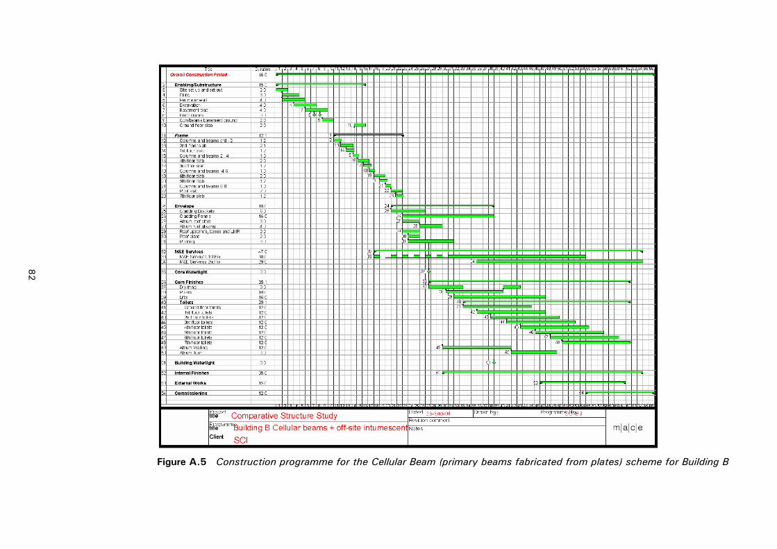
Figure A.5 Construction programme for the Cellular Beam (primary beams fabricated from plates) scheme for Building B
82
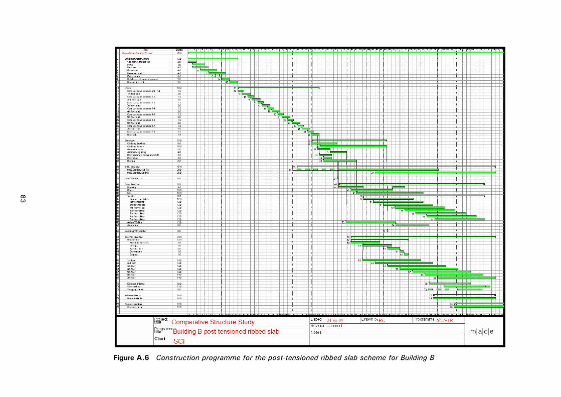
Figure A.6 Construction programme for the post-tensioned ribbed slab scheme for Building B
83

84

P137v02d10.doc 85 Printed 08/11/04
APPENDIX B REVIEW AT AUGUST 2004
Since the beginning of 2004, the increase in global demand for steel has led to significant price increases for all steel products; reinforcing bars as well as structural steel sections. The impact of these increases on building costs is worth considering in the context of the present study.
In the light of these increases, some typical options reported in the study have been re-costed at prices prevailing at August 2004.
In Building A, the schemes comprise:
• Slimdek® (unpropped).
• Composite beam and composite slab.
• Reinforced flat slab.
• In-situ concrete frame with hollow core units.
In Building B, the schemes comprise:
• Slimdek® (unpropped).
• Cellular beams (long-span secondary beams).
• Reinforced flat slab.
• Post-tensioned ribbed slab.
These schemes were chosen because they are the most economic steel and concrete short-span and long-span options. No revision was made to the structural designs or specification of the buildings.
The average cost increase (total and net costs) for Building A was 5.3% for the steel schemes and 4.0% for the concrete schemes. Comparable values for Building B were 2.9% (steel schemes) and 2.5% (concrete schemes). It can therefore be assumed that the overall competitive position of the steel schemes relative to the concrete schemes is virtually unchanged.