comparision of hydraulic gradient and...
TRANSCRIPT

SAJCCE 1:1 (2015) 91-103 October 2015 ISSN: 2394-2258 Available at http://scientificadvances.co.in DOI: http://dx.doi.org/10.18642/sajcce_7100121544
*Corresponding author. E-mail address: [email protected]; [email protected] (Farzin Salmasi).
Copyright 2015 Scientific Advances Publishers Received September 25, 2015
COMPARISION OF HYDRAULIC GRADIENT AND UPLIFT PRESSURE IN THREE TYPES OF DAMS:
HOMOGENEOUS, HETEROGENEOUS EARTHFILL DAMS AND CONCRETE GRAVITY DAM
Farzin Salmasi and Behnam Mansuri
Department of Water Engineering, Faculty of Agriculture, University of Tabriz, Tabriz, Iran
___________________________________________________________________
Abstract
This study focuses on the hydraulic gradient and uplift pressure in three types of dams, i.e., homogeneous, heterogeneous earth dams, and concrete gravity dam. For this purpose, three type of dam with the same boundary conditions. Seepage, hydraulic gradient, and uplift pressure, are computing by numerical simulation, using Seep/w software. Results show that hydraulic gradient for two types of dams, i.e., concrete gravity and homogeneous earth dams, are near together and are less than 0.5. Hydraulic gradient became more than 2.5 in beginning and ending of clay core of heterogeneous earth dam. Implementation of filter material in such zones will be necessary to prevent dam foundation from piping/undermining phenomenon. Value of uplift pressure for earth dams are more than for concrete gravity dam.
Keywords: earth dam, hydraulic gradient, seepage, Seep/w, uplift pressure.
___________________________________________________________________
F. Salmasi and B. Mansuri / SAJCCE 1:1 (2015) 91-103 92
1. Introduction
Among the various failures of earth dams, failure resulting from a quick condition, and piping in foundation soils due to high seepage pressures is highly dangerous. If piping is not halted, it may result in a catastrophic collapse of the structure. Seepage through the earth dams and its foundation is controlled by two approaches, which are generally used in combination (Peter [13]). The first approach involves reduction of the quantity of seepage, which may be achieved by providing antiseepage elements of passive protection, e.g., sheet pile (steel, wooden), cutoff wall, slurry trench, clay sealing, upstream impervious blanket, grout curtain, concrete wall, diaphragm wall, etc. The second approach involves providing a safe outlet for seepage water, which still enters the earth dams or the foundation. This may be achieved by providing antiseepage elements of active protection such as filters, drains, sand drains, stone columns, ditches, and relief wells (Sherard et al. [19]; Peter [13]).
About 30% of dams had failed due to the seepage failure, viz piping, and sloughing (Middlebrooks [12]). Recent comprehensive reviews by Foster et al. [7, 8] and Fell et al. [5] show that internal erosion and piping are the main causes of failure and accidents affecting embankment dams; and the proportion of their failures by piping increased from 43% before 1950 to 54% after 1950. The sloughing of the downstream face of a homogeneous earth dam occurs under the steady-state seepage condition due to the softening and weakening of the soil mass when the top flow line or phreatic line intersects it. Regardless of flatness of the downstream slope and impermeability of soil, the phreatic line intersects the downstream face to a height of roughly one-third the depth of water (Justin et al. [11]). It is usual practice to use a modified homogeneous section in which an internal drainage system in the form of a horizontal blanket drain or a rock toe or a combination of the two is provided. The drainage system keeps the phreatic line well within the body of the dam (Chahar [3]).
COMPARISION OF HYDRAULIC GRADIENT … / SAJCCE 1:1 (2015) 91-103 93
Horizontal filtered drainage blankets are widely used for dams of moderate height. Lion Lake dike (6.5m high), Pishkun dikes (13m high), Stubblefield dam (14.5m high), Dickinson dam (15m high), etc. are examples of small homogeneous dams built by USBR (2003). Also, USBR constructed the 50m high Vega dam, which is one of the highest with a homogeneous section and a horizontal downstream drain. Design criteria of filtered drainage can be found in many references (Terzaghi and Peck [20]; Vaughan and Soares [23]; Sherard et al. [17, 18]; Sherard and Dunnigan [16]; Honjo and Veneziano [9]; Sharma [15]).
Concrete cut off walls are one of main methods of seepage control and are divided to the following categories according to the material type used in construction (Shahbazian Ahari et al. [14]):
● Slurry trench cut off wall.
● Bentonite-cement cut off wall.
● Concrete cut off wall.
● Plastic concrete cut off wall.
The plastic concrete is an appropriate kind of material due to its high deformability (ICOLD [10]).
In Zoorasna et al. [24] study, seepage and stress-strain analysis used to investigate the mechanical performance of cut off wall-core connecting systems in earth dams. Karkheh storage dam in Iran was used as the case study and six different connecting systems were modelled. Total flow, maximum hydraulic gradient, shear stress, shear strains, and percent of plastic points were determined in connection zone.
Explicit equations have been obtained in the Chahar [3] work for calculating the downstream slope cover and the length of the downstream horizontal drain in homogeneous isotropic and anisotropic earth dams. Similar equations have also been obtained for maximum downstream slope cover and minimum and maximum effective length of the filtered drainage. These equations are nonlinear and representative graphs have been plotted for them covering all the practical ranges of the dam geometry.
F. Salmasi and B. Mansuri / SAJCCE 1:1 (2015) 91-103 94
In the present study, different horizontal drain lengths and cut off wall systems are used to investigate the effect on seepage and uplift pressure in a proposed inhomogeneous earth dam. Cut off location varies from dam heel to dam toe. Numerical simulation carries out using Seep/w software in steady-state conditions.
2. Materials and Methods
Seep/w is formulated on the basis that the flow of water through both saturated and unsaturated soil follows Darcy’s law which states that (Anonymous [1]):
,iq k−= (1)
where =q the specific discharge,
=k the hydraulic conductivity, and
=i the gradient of total hydraulic head.
Darcy’s law was originally derived for saturated soil, but later research has shown that it can also be applied to the flow of water through unsaturated soil. The only difference is that under conditions of unsaturated flow, the hydraulic conductivity is no longer a constant, but varies with changes in water content and indirectly varies with changes in pore-water pressure
The general governing differential equation for two-dimensional seepage can be expressed as
( ) ( ) ,tyh
yxh
x yx ∂θ∂=+
∂∂
∂∂+
∂∂
∂∂ Qkk (2)
where xk and yk are the coefficients of hydraulic conductivity in the x
and y direction, respectively (meter per second), h is the total head (meters) and =Q the applied boundary flux (cubic meter per second per
unit area), θ is the volumetric water content, and =t time.
COMPARISION OF HYDRAULIC GRADIENT … / SAJCCE 1:1 (2015) 91-103 95
Equation (2) states that the difference between the flow (flux) entering and leaving an elemental volume at a point in time is equal to the change in storage of the soil systems. More fundamentally, it states that the sum of the rates of change of flows in the x- and y-directions plus the external applied flux is equal to the rate of change of the volumetric water content with respect to time.
Under steady-state conditions, the flux entering and leaving an elemental volume is the same at all times. The right side of the equation consequently vanishes and the equation reduces to
( ) ( ) .0=+∂∂
∂∂+
∂∂
∂∂ Qy
hyx
hx yx kk (3)
3. Numerical Simulation
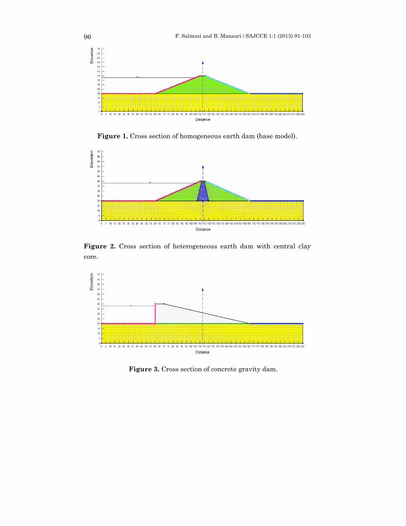
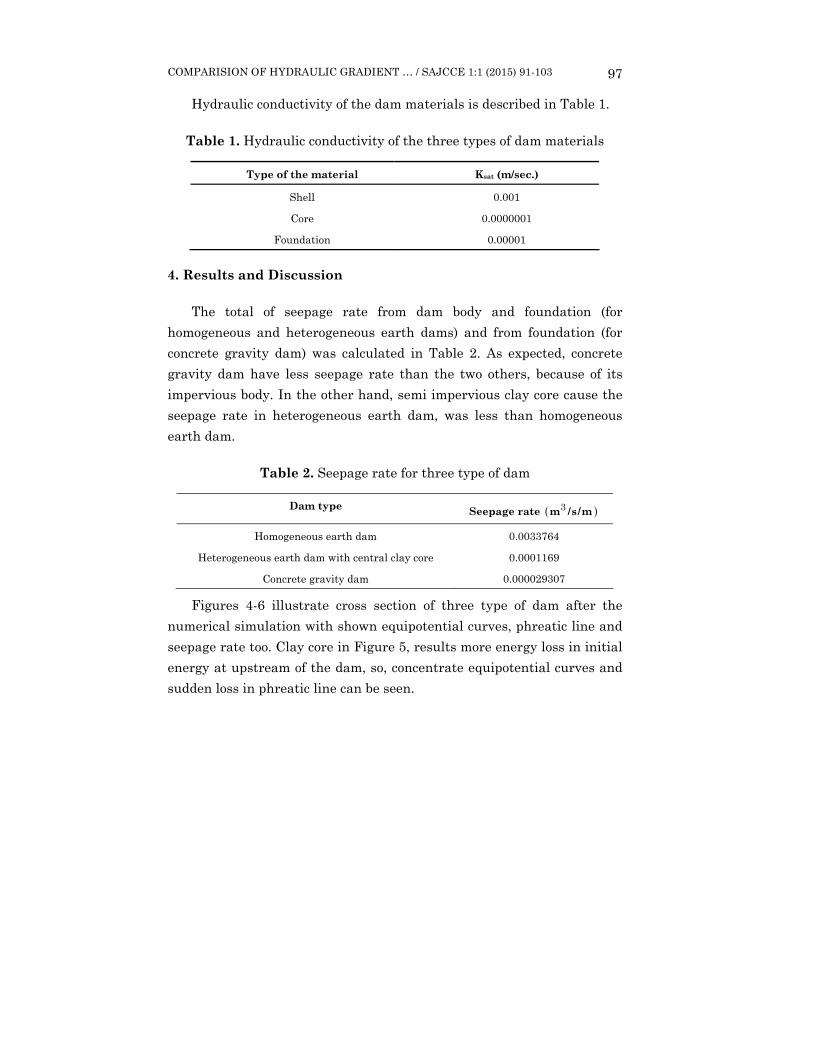
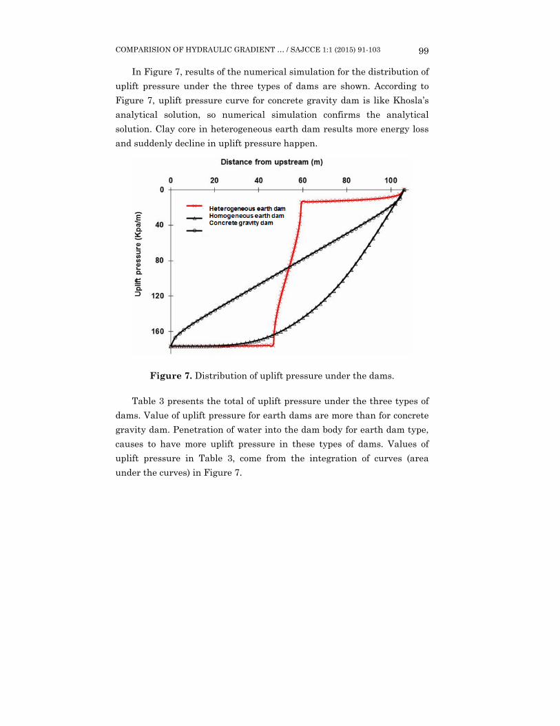
In this study, three types of dams, i.e., homogeneous, heterogeneous earth dams, and concrete gravity dam were modelled by finite elements using Seep/w software (Figures 1-3).
The upstream and downstream slope of homogeneous dam have inclination 1V:2.5H and the upstream and downstream slope for dam core (heterogeneous type) have inclination of 1V:0.25H.
Boundary conditions are the same for these three types of dams. Water level (total head) in upstream of dam is 38 meter, water level in downstream is assumed equal to 20 meters. Also, the foundation’s floor and its right and left walls and the downstream slope of the dam are impermeable (zero flow). Node at the toe of dams is atmospheric pressure (zero pressure).
Simulation of two dimensional (2D) of dams are in steady state condition. In Figures 1-3, cross section of dams’ model has 225m length and 20m depth. Several simulations demonstrated that the value of seepage discharge and its hydraulic gradients has a little variation with longer and deeper models. As can be seen in Figure 2, there are smaller elements in the core of dam for more accuracy.
F. Salmasi and B. Mansuri / SAJCCE 1:1 (2015) 91-103 96
Figure 1. Cross section of homogeneous earth dam (base model).
Figure 2. Cross section of heterogeneous earth dam with central clay core.
Figure 3. Cross section of concrete gravity dam.
COMPARISION OF HYDRAULIC GRADIENT … / SAJCCE 1:1 (2015) 91-103 97
Hydraulic conductivity of the dam materials is described in Table 1.
Table 1. Hydraulic conductivity of the three types of dam materials
Type of the material Ksat (m/sec.)
Shell 0.001
Core 0.0000001
Foundation 0.00001
4. Results and Discussion
The total of seepage rate from dam body and foundation (for homogeneous and heterogeneous earth dams) and from foundation (for concrete gravity dam) was calculated in Table 2. As expected, concrete gravity dam have less seepage rate than the two others, because of its impervious body. In the other hand, semi impervious clay core cause the seepage rate in heterogeneous earth dam, was less than homogeneous earth dam.
Table 2. Seepage rate for three type of dam
Dam type Seepage rate ( )m/s/m3
Homogeneous earth dam 0.0033764
Heterogeneous earth dam with central clay core 0.0001169
Concrete gravity dam 0.000029307
Figures 4-6 illustrate cross section of three type of dam after the numerical simulation with shown equipotential curves, phreatic line and seepage rate too. Clay core in Figure 5, results more energy loss in initial energy at upstream of the dam, so, concentrate equipotential curves and sudden loss in phreatic line can be seen.

F. Salmasi and B. Mansuri / SAJCCE 1:1 (2015) 91-103 98
Figure 4. Cross section of homogeneous earth dam earth after the numerical simulation.
Figure 5. Cross section of heterogeneous earth dam earth after the numerical simulation.
Figure 6. Cross section of concrete gravity dam earth after the numerical simulation.
COMPARISION OF HYDRAULIC GRADIENT … / SAJCCE 1:1 (2015) 91-103 99
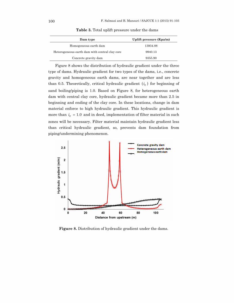
In Figure 7, results of the numerical simulation for the distribution of uplift pressure under the three types of dams are shown. According to Figure 7, uplift pressure curve for concrete gravity dam is like Khosla’s analytical solution, so numerical simulation confirms the analytical solution. Clay core in heterogeneous earth dam results more energy loss and suddenly decline in uplift pressure happen.
Figure 7. Distribution of uplift pressure under the dams.
Table 3 presents the total of uplift pressure under the three types of dams. Value of uplift pressure for earth dams are more than for concrete gravity dam. Penetration of water into the dam body for earth dam type, causes to have more uplift pressure in these types of dams. Values of uplift pressure in Table 3, come from the integration of curves (area under the curves) in Figure 7.
F. Salmasi and B. Mansuri / SAJCCE 1:1 (2015) 91-103 100
Table 3. Total uplift pressure under the dams
Dam type Uplift pressure (Kpa/m)
Homogeneous earth dam 13934.88
Heterogeneous earth dam with central clay core 9940.13
Concrete gravity dam 9355.90
Figure 8 shows the distribution of hydraulic gradient under the three type of dams. Hydraulic gradient for two types of the dams, i.e., concrete gravity and homogeneous earth dams, are near together and are less than 0.5. Theoretically, critical hydraulic gradient ( )ci for beginning of
sand boiling/piping is 1.0. Based on Figure 8, for heterogeneous earth dam with central clay core, hydraulic gradient became more than 2.5 in beginning and ending of the clay core. In these locations, change in dam material enforce to high hydraulic gradient. This hydraulic gradient is more than 0.1=ci and in deed, implementation of filter material in such
zones will be necessary. Filter material maintain hydraulic gradient less than critical hydraulic gradient, so, prevents dam foundation from piping/undermining phenomenon.
Figure 8. Distribution of hydraulic gradient under the dams.

COMPARISION OF HYDRAULIC GRADIENT … / SAJCCE 1:1 (2015) 91-103 101
5. Conclusion
By numerical modelling of in three types of dams, i.e., homogeneous, heterogeneous earth dams, and concrete gravity dam using Seep/w software, hydraulic gradient, and uplift pressure under dam foundations were investigated. Based on the study, the following conclusions are drawn:
− Numerical simulation confirms analytical solution of Khosla.
− Hydraulic gradient for two types of dams, i.e., concrete gravity and homogeneous earth dams, are near together and are less than 0.5.
− Hydraulic gradient became more than 2.5 in beginning and ending of clay core of heterogeneous earth dam. Implementation of filter material in such zones will be necessary to prevent dam foundation from piping/undermining phenomenon.
− Value of uplift pressure for earth dams are more than for concrete gravity dam. Penetration of water into dam body for earth dam type causes to have more uplift pressure in these types of dams.
Notation
The following symbols are used in this paper:
=h potential head in porous media of dam;
=i the gradient of total hydraulic head;
=xk horizontal hydraulic conductivity of shell material;
=yk vertical hydraulic conductivity of shell material;
=q the specific discharge;
=Q applied boundary flux;
=t time;
=θ volumetric water content.

F. Salmasi and B. Mansuri / SAJCCE 1:1 (2015) 91-103 102
References
[1] Anonymous, Seepage Modeling with SEEP/W 2007, An Engineering Methodology, Third Edition, 2008, pp. 263.
[2] H. R. Cedergren, Seepage, Drainage and Flow Nets, Second Edition, John Wiley and Sons, Inc., New York, 1977.
[3] B. R. Chahar, Determination of length of a horizontal drain in homogeneous earth dams, Journal of Irrigation and Drainage Engineering, ASCE 130(6) (2004), 530-536.
[4] A. K. Chugh, Flow nets for zoned anisotropic media by the boundary element method, Computers and Structures 29(2) (1988), 207-220.
[5] R. Fell, C. F. Wan, J. Cyganiewicz and M. Foster, Time for development of internal erosion and piping in embankment dams, J. Geotech, Geoenviron. Eng. 129(4) (2003), 307-314.
[6] W. D. Liam Finn, Finite element analysis of seepage through dams, J. Soil Mech. Found. Div. 93(6) (1967), 41-48.
[7] M. Foster, R. Fell and M. Spannagle, The statistics of embankment embankment dam failures and accidents, Can. Geotech. J. 37(5) (2000a), 1000-1024.
[8] M. Foster, R. Fell and M. Spannagle, A method for assessing the relative likelihood of failure of embankment dams by piping, Can. Geotech. J. 37(5) (2000b) 1025-1061.
[9] Y. Honjo and D. Veneziano, Improved filter criterion for cohesion less soils, J. Geotech. Eng. 115(1) (1989) 75-94.
[10] ICOLD, Filling Materials for Watertight Cut off Walls, Bull. No. 51, 1985.
[11] J. D. Justin, J. Hinds and W. P. Creager, Engineering for Dams: Earth, Rock Fill, Steel and Timber Dams, Vol. III, Wiley, New York, 1944.
[12] T. A. Middlebrooks, Earth dam practice in the United States, Trans. Am. Soc. Civ. Eng. 118 (1953), 697-722.
[13] P. Peter, Canal and river levees, Developments in Geotechnical Engineering, Vol. 29, Elsevier Scientific, Amsterdam, The Netherlands, 540, 1982.
[14] R. Shahbazian Ahari, A. A. Mirghassemi and M. Pakzad, Investigation of the Interaction between Dam, Foundation and the Concrete Cut off Wall, Proc. of 4th Conf. on Dam Engrg. Iran, (2000), 452-459.
[15] H. D. Sharma, Embankment Dams, Oxford & IBH, New Delhi, 1991.
[16] J. L. Sherard and L. P. Dunnigan, Filter and leakage control in embankment dams, Proc., Symp. Seepage and Leakage from Dams and Impoundments, ASCE, New York, 1985, pp. 1-30.
[17] J. L. Sherard, L. P. Dunnigan and J. R. Talbot, Basic properties of sand and gravel filters, J. Geotech. Eng. 110(6) (1984a), 684-700.
[18] J. L. Sherard, L. P. Dunnigan and J. R. Talbot, Filters for silts and clays, J. Geotech. Eng. 110(6) (1984b), 701-718.
COMPARISION OF HYDRAULIC GRADIENT … / SAJCCE 1:1 (2015) 91-103 103
[19] J. L. Sherard, S. F. Gizienski and W. A. Clevenger, Earth and Earth-rock Dams, Wiley, New York, 725, 1963.
[20] K. Terzaghi and R. B. Peck, Theoretical Soil Mechanics, Wiley, New York, 1967.
[21] United States Bureau of Reclamation, USBR, Design of Small Dams, Oxford & IBH, New Delhi, 2003.
[22] A. Uromeihy and G. Barzegari, Evaluation and treatment of seepage problems at Chapar-Abad Dam, Iran, Journal of Engineering Geology (91) (2007), 219-228.
[23] P. R. Vaughan and H. F. Soares, Design of filters for clay cores of dams, J. Geotech. Eng. Div., Am. Soc. Civ. Eng. 108(1) (1982), 17-31.
[24] Z. Zoorasna, A. Hamidi and A. Ghanbari, Mechanical and hydraulic behavior of cut off-core connecting systems in earth dams, EJGE, Bund. K. (2008), 1-12.
g