comparison of slab design between bs 8110 and
TRANSCRIPT
COMPARISON OF SLAB DESIGN BETWEEN BS 8110 AND EUROCODE 2 BY USING MICROSOFT EXCEL
KAMARUL AR1FFIN BIN MOHD MARPAL
A thesis submitted in fulfillment of the requirements for the award of the degree of Bachelor of Civil Engineering
Faculty of Civil Engineering and Earth Resources Universiti Malaysia Pahang
1
DECEMBER 2010
ABSTRACT
This project is to develop a program that able to analyze and design of
reinforced concrete slabs using the application of spreadsheet Microsoft Excel. The
analysis and design of slabs is in accordance with BS' 8110 Part 1: 1997 and
Eurocode 2 - Design of concrete structures. Thus, this research focuses on the
application of those design codes in the form of spreadsheets from Microsoft Excel
for the purpose of analyzing and designing of reinforced concrete slab. Basically, the
procedures in designing this element require numerous calculations in order to reach
the most desired and economical design. Spreadsheet in Microsoft Excel has the
capability of solving problems related to equations and formulas in a short time
which makes design calculations and procedures easier. Besides that, Microsoft
Excel is easily available and also presented in a user-friendly manner. A software has
been developed with design procedures based on BS 8110 and Eurocode 2, which is
the design of concrete slabs. Necessary checking such as deflection and crack control
is also calculated by the software which helps to improve the accuracy of the design.
The calculation done by the software was compared to manual calculation to ensure
the reliability of this software. Results and conclusions show that this software
fulfills the research objectives which are to develop software to aid designers in the
designing using BS 8110 and Eurocode 2.
VII

ABSTRAK
Kajian yang dilakukan mi adalah untuk menyediakan satu program yang
mampu menganalisis dan mereka bentuk papak konkrit bertetulang secara tepat dan
cepat dengan menggunakan aplikasi program Microsoft Excel. Analisis dan reka
bentuk papak adalah berpandukan kepada BS 8110 Part 1: 1997 dan Eurocode 2 -
Design of concrete structures. Oleh demikian, kajian jul memberi fokus kepada
perlaksanaan kod-kod tersebut dalam bentuk spreadsheet perisian Microsoft Excel
bagi tujuan menganalisis dan merekabentuk struktur papak konkrit bertetulang. Pada
asasnya, prosedur untuk merekabentuk struktur tersebut memerlukan pengiraan
berkali-kali bagi mencapai rekabentuk yang ekonomi dan diingini. Spreadsheet
dalam Microsoft Excel dapat menyelesaikan masalah berkaitan dengan pengiraan
persamaan dan formula dalam masa yang singkat, membuatkan rekabentuk prosedur
dapat diselesaikan dengan lebih mudah. Selain itu, Microsoft Excel juga mudah
diperolehi dan digunakan. Satu perisian telah dibangunkan berpandukan prosedur
rekabentuk dalam BS 8110 dan Eurocode 2, iaitu rekabentuk papak. Pemeriksaan
yang perlu dalam rekabentuk seperti keretakan dan pesongan juga akan dikira oleh
perisian mi, justeru membantu meningkatkan ketepatan rekabentuk. Kiraan yang
dibuat oleh perisian mi telah dibandingkan dengan pengiraan manual bagi
memastikan ketepatamiya. Keputusan dan kesimpulan pada akhir kajian dalam
membangunkan perisian mi memenuhi objektif kajian, iaitu untuk membangunkan
perisian rekabentuk bagi membantu parajurutera dalam merekabentuk menggunakan
BS 8110 dan Eurocode 2.
VIII
ix
TABLES OF CONTENT
CHAPTER ITEM PAGE
TITLE i
STATUS VALIDATION
DECLARATION
DEDICATION v
ACKNOWLEDGEMENT vi
ABSTRACT vii
ABSTRAK viii
TABLE OF CONTENTS ix
LIST OF TABLES xiii
LIST OF FIGURES xiv
INTRODUCTION 1
1.1 Introduction 1
1.2 Problem Statements 2
1.3 Research Objective 3
1.4 Scope of Research 3
2 LITERATURE REVIEW 4
2.1 Introduction 4
2.2 British Standard 5
2.2.1 Codes of Practices 6
2.2.2 Types of slab 6
2.2.3 One way slab 6
2.2.3.1 One way simply supported slab 7
2.2.3.2 One way continuous slab 8
2.2.4 Two way slab 8
2.2.4.1 Two way simply supported slab 9
xi
Moments and Shear Forces
2.3.11 Material Properties 27
2.3.11.1 Concrete 27
2.3.11.2 Reinforcing Steel 27
2.3.12 Structural Analysis 28
2.3.12.1 Analysis of One Way and Two 29
Way Slab
2.3.12.2 Design for Shear 31
2.3.12.3 Spacing and Quantity of 32
Reinforcement
2.3.12.4 Deflection and Crack Control 33
2.3.12.5 Bond and Anchorage 35
3 METHODOLOGY 37
3.1 Introduction 37
3.2 Tools and equipment 38
3.3 Limit of Study 38
3.4 Design Using Microsoft Excel 39
3.5 Flow Chart Establishment 39
3.5.3 Flow Charts for Slab Design using BS 8110 39
3.5.4 Flow Charts for Slab Design using Eurocode 2 42
4 RESULT AND DISCUSSION 45
4.1 Introduction 45
4.2 Challenges 45
4.3 Software Development 46
4.4 Data Erroneous 47
4.5 Manual Calculation and Excel Comparison 47
4.6 User Manual 48
4.7 Computerized Design Procedures 51
4.8 Slab Design Using BS81 10 52
4.8.1 Analysis of Actions and Slab Type 52
Determination
XII
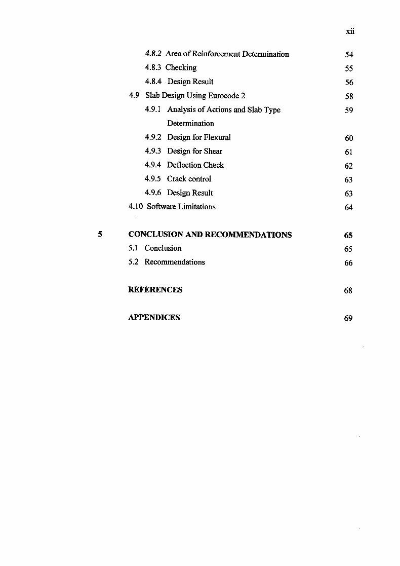
4.8.2 Area of Reinforcement Determination 54
4.8.3 Checking 55
4.8.4 Design Result 56
4.9 Slab Design Using Eurocode 2 58
4.9.1 Analysis of Actions and Slab Type 59
Determination
4.9.2 Design for Flexural 60
4.9.3 Design for Shear 61
4.9.4 Deflection Check 62
4.9.5 Crack control 63
4.9.6 Design Result 63
4.10 Software Limitations 64
5 CONCLUSION AND RECOMMENDATIONS 65
5.1 Conclusion 65
5.2 Recommendations 66
REFERENCES 68
APPENDICES 69
xlii
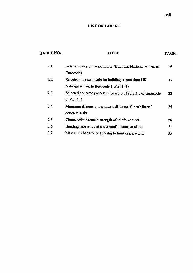
LIST OF TABLES
TABLE NO. TITLE PAGE•
2.1 Indicative design working life (from UK National Annex to 16
Eurocode)
2.2 Selected imposed loads for buildings (from draft UK 17
National Annex to Eurocode 1, Part 1=1)
2.3 Selected concrete properties based on Table 3.1 of Eurocode 22
2, Part 1-1
2.4 Minimum dimensions and axis distances for reinforced 25
concrete slabs
2.5 Characteristic tensile strength of reinforcement 28
2.6 Bending moment and shear coefficients for slabs 31
2.7 Maximum bar size or spacing to limit crack width 35
xiv
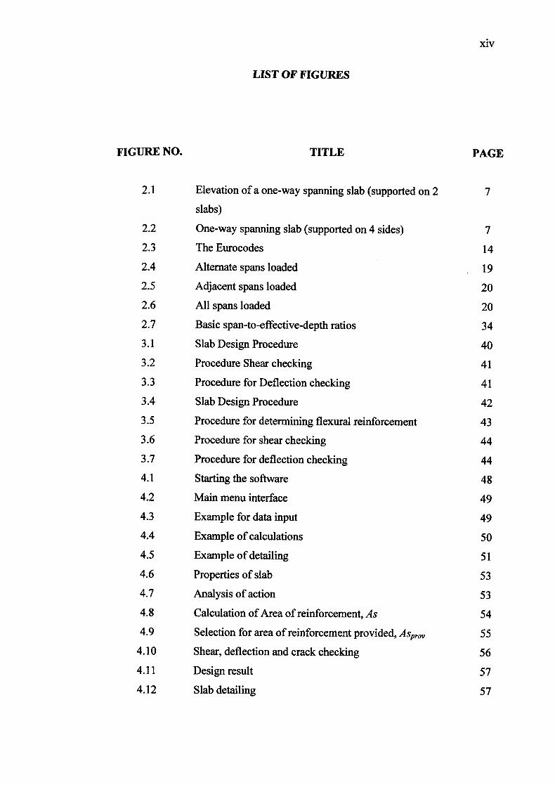
LIST OF FIGURES
FIGURE NO. TITLE PAGE
2.1 Elevation of a one-way spanning slab (supported on 2 7
slabs)
2.2 One-way spanning slab (supported on 4 sides) 7
2.3 The Eurocodes 14
2.4 Alternate spans loaded 19
2.5 Adjacent spans loaded 20
2.6 All spans loaded 20
2.7 Basic span-to-effective-depth ratios 34
3.1 Slab Design Procedure 40
3.2 Procedure Shear checking 41
3.3 Procedure for Deflection checking 41
3.4 Slab Design Procedure 42
3.5 Procedure for determining flexural reinforcement 43
3.6 Procedure for shear checking 44
3.7 Procedure for deflection checking 44
4.1 Starting the software 48
4.2 Main menu interface 49
4.3 Example for data input 49
4.4 Example of calculations 50
4.5 Example of detailing 51
4.6 Properties of slab 53
4.7 Analysis of action 53
4.8 Calculation of Area of reinforcement, As 54
4.9 Selection for area of reinforcement provided, ASprov 55
4.10 Shear, deflection and crack checking 56
4.11 Design result 57
4.12 Slab detailing 57

xv
4.13 Design specification and detail 58
4.14 Properties of slab 59
4.15 Flexural design of slabs 60
4.16 Selection for area of reinforcement provided, ASprov 61
4.17 Shear analysis for slab 62
4.18 Deflection checking 62
4.19 Crack control 63
4.20 Design result 64

CHAPTER 1
INTRODUCTION
1.1 Introduction
Design is the process which made by engineer to determine the type, size and
material used through a meticulous calculation until detail drawing produced. Design
is involve at all element of building such as slab, beam, column, foundation, roof and
many more. Slab design will consider all aspect like bending moment, shear force,
cracking and area of reinforcement.
Reinforced slab is a flat element that used in floors, roofs and walls of
buildings and as the decks of bridges. The floor system of a structure can take many
forms such as in situ solid slabs, ribbed slabs or precast units. Slabs may span in one
direction or in two directions and they may be supported on monolithic concrete
beams, steel beams, walls or directly by the structure's columns.

2
Usually in Malaysia, the design of structures will be guided by using British
Standard, (BS 8110). BS 8110 is a British Standard for the design and construction
of reinforced and prestressed concrete structures. It is based on limit state design
principles. Although used for most civil engineering and building structures, bridges
and water-retaining structures are covered by separate standards (BS 5400 and BS
8007).
The Eurocodes are a new set of European structural design codes for building
and civil engineering works. Nowadays, Eurocode are being introduced and applied
for design concrete structures still not yet widely use in Malaysia. The Eurocodes are
intended to be mandatory for European public works and likely to become the de-
facto standard for the private sector - both in Europe and world-wide.
1.2 Problem Statement
There are several problem have contributed to the needs of this research and
the development of this software. The problems are:
i. Manual and countless calculations could lead to numerous mistakes and
delay in design.
ii. Little knowledge and attention of the construction community about the
newly developed Eurocodes.
iii. Learning to use the new Eurocode 2 will require time and effort. Therefore
using programming methods on the new design elements will help
designers on the transition to the adaptation of the new code.
3
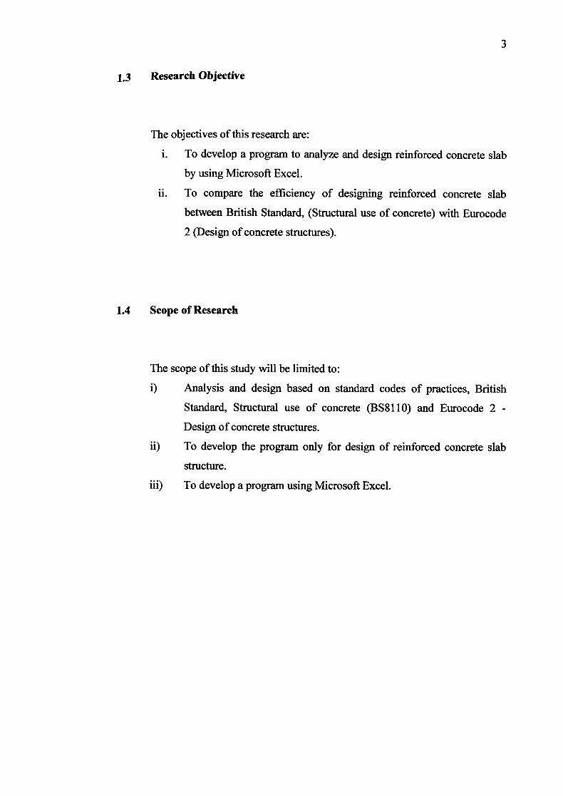
13 Research Objective
The objectives of this research are:
i. To develop a program to analyze and design reinforced concrete slab
by using Microsoft Excel.
ii. To compare the efficiency of designing reinforced concrete slab
between British Standard, (Structural use of concrete) with Eurocode
2 (Design of concrete structures).
1.4 Scope of Research
The scope of this study will be limited to:
i) Analysis and design based on standard codes of practices, British
Standard, Structural use of concrete (BS81 10) and Eurocode 2 -
Design of concrete structures.
ii) To develop the program only for design of reinforced concrete slab
structure.
iii) To develop a program using Microsoft Excel.
CHAPTER 2
LITERATURE REVIEW
2.1 Introduction
This chapter discusses on the history and development of British Standard
(BS 8110: Part 1:1997) and Eurocode 2- Design of concrete structures. The
introduction and application of this code is a significant event in civil engineering, so
this chapter will look closely on British Standard and Eurocode 2 and also its
applications. The scope of this research is designing principles for slab design, so
further details on design procedures of slabs will be discussed in this section.
The procedures and process of design based on Eurocode 2 does not change
in adaptation. This section will point out the main outline in design procedures.
Learning to use new codes will require time and effort, so the development of this
research is hoped to ease the transition to using Eurocode 2 as the new design
standards. Other than that, the principles and aims will also be discussed in this
section.
5
2.2 British Standard
British Standards are the standards produced by BSI Group which is
incorporated under a Royal Charter (and which is formally designated as the
National Standards Body (NSB) for the UK). The BSI Group produces British
Standards under the authority of the Charter, which lays down as one of the BSI's
objectives to set up standards of quality for goods and services, and prepare and
promote the general adoption of British Standards and schedules in connection
therewith and from time to time to revise, alter and amend such standards and
schedules as experience and circumstances require.
BSI Group began in 1901 as the Engineering Standards Committee, to
standardise the number and type of steel sections, in order to make British
manufacturers more efficient and competitive. BSI Group currently has over 27,000
active standards. Products are commonly specified as meeting a particular British
Standard, and in general this can be done without any certification or independent
testing. The standard simply provides a shorthand way of claiming that certain
specifications are met, while encouraging manufacturers to adhere to a common
method for such a specification.
BS 8110 is a British Standard for the design and construction of reinforced
and prestressed concrete structures. It is based on limit state design principles.
Although used for most civil engineering and building structures, bridges and water-
retaining structures are covered by separate standards (BS 5400 and BS 8007). In
2010, BS 8110 was superseded by EN 1992 (Eurocode 2) although parts of the
standard have been retained in the National Annex of the Eurocode.
2.2.1 Codes of Practices
Practical codes of practice are a document on best practices has been
experienced before by experienced engineer and researcher. In this study the
design referring to BS 811 0:Part 1:1997.
2.2.2 Types of slab
Slab consists of two types which are one way slab and two way slabs.
One way slab have two types namely simply supported slab and one way
continuous slab. While two way slabs also consists two types namely simply
supported two way slab and constrained slab. Slab types can be decided
through side ratio calculation through BS8 110 reference such as:
Ly / Lx <2.0 (two way)
Ly / Lx > 2.0 (one-way)
with Ly was longer side and Lx was shorter side.
2.2.3 One way slab
Slab is called one-way if the main reinforcement designs within one
direction only. This situation happens if slab is supported only on two sides
only. If slab were supported at all four sides, slab will become one way if
long span ratio (Ly) to short span (Lx) is exceeding 2. Because of slab string
one-way then reinforcement in span direction is main reinforcement, while
reinforcement in direction perpendicular by span known as second
reinforcement which functions as binding main reinforcement and help stress
distribution because of temperature changes and concrete shrinkage.

7
2.23.1 One way simply supported slab
In a one-way spanning slab, the main reinforcement is
designed to span in one direction only. This can only happen when the
slab is supported only on its two sides as shown in Figure 2.1 below;
I I I I I I I I
I I I I I I I I I I I I
Figure 2.1: Elevation of a one-way spanning slab (supported on 2 slabs)
For slabs supported on four sides as shown in Figure 2.2
below, it is considered as a one-way spanning slab if the ratio L / L
is greater than 2. L is the longer side and L the shorter side.
L
P11
I I
I I ------------------------------I-.-I I
_________________________________
L
Figure 2.2: One-way spanning slab (supported on 4 sides)
8
For these types of slabs, the main reinforcement is in the
direction of span because the slab is spanning in one direction.
Reinforcement, which is perpendicular to the direction of span, is also
known as distribution bars. They act as ties to the main reinforcement
and help to distribute any stress caused by any change in temperature
and shrinkage of concrete. The analysis and design of simply
supported one-way spanning slab is similar to the analysis and design
of simply supported beams.
2.2.3.2 One way continuous slab
For one way continuous slab, moment and shear force can be
determine from Table 3.13: BS 8110, if following terms filled.
i. Area of each bay exceeding 30 m2
ii. Imposed load is less than 1.25 times dead load
iii. Imposed load not exceeding 5.0 kN/m2
2.2.4 Two way slab
Main reinforcement for two way slabs designs in both directions.
This situation happen when slab were supported at all four span sides and
ratio long per short span less or equivalent to two. Bending moment and shear
force for two way slab depends on ratio ly / lx and extension between his slab
and supporter whether easily supported or constrained.
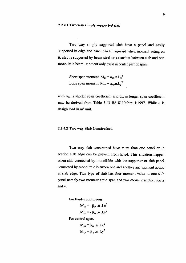
2.2.4.1 Two way simply supported slab
Two way simply supported slab have a panel and easily
supported in edge and panel can lift upward when moment acting on
it, slab is supported by beam steel or extension between slab and non
monolithic beam. Moment only exist in center part of span.
Short span moment,
Long span moment, Msy =
with asx is shorter span coefficient and is longer span coefficient
may be derived from Table 3.13 BS 8110:Part 1:1997. While n is
design load in m2 unit.
2.2.4.2 Two way Slab Constrained
Two way slab constrained have more than one panel or in
section slab edge can be prevent from lifted. This situation happen
when slab connected by monolithic with the supporter or slab panel
connected by monolithic between one and another and moment acting
at slab edge. This type of slab has four moment value at one slab
panel namely two moment amid span and two moment at direction x
and y.
For border continuous,
Msx = — Psx.n .Lx2
Msy = - .n
For central span,
= .n .Lx2
Msy = .n
10
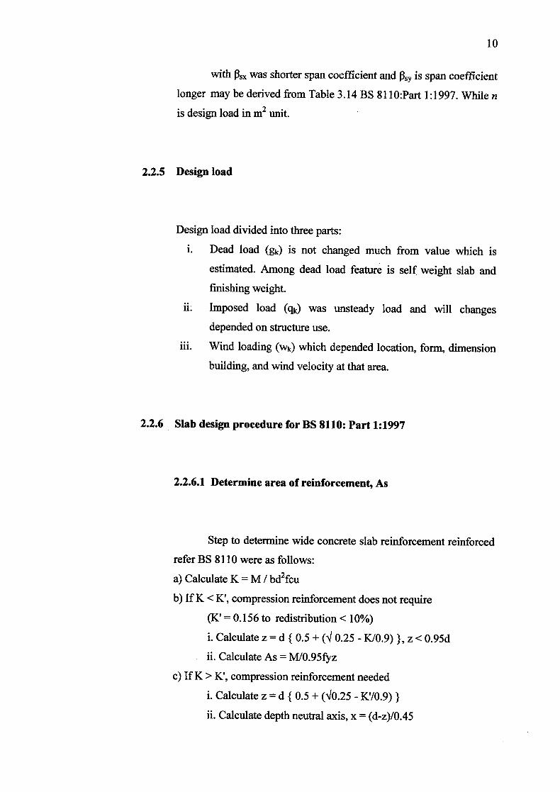
with Psx was shorter span coefficient and P,y is span coefficient
longer may be derived from Table 3.14 BS 811 O:Part 1:1997. While n
is design load in m2 unit.
2.2.5 Design load
Design load divided into three parts:
L Dead load (ga) is not changed much from value which is
estimated. Among dead load feature is self weight slab and
finishing weight.
ii. Imposed load (q) was unsteady load and will changes
depended on structure use.
iii. Wind loading (Wk) which depended location, form, dimension
building, and wind velocity at that area.
2.2.6 Slab design procedure for BS 8110: Part 1:1997
2.2.6.1 Determine area of reinforcement, As
Step to determine wide concrete slab reinforcement reinforced
refer BS 8110 were as follows:
a) Calculate K = M / bd2fcu
b) If K < K', compression reinforcement does not require
(K' = 0.156 to redistribution < 10%)
i. Calculate z = d 10.5 + ('J 0.25 - KI0.9) }, z < 0.95d
ii. Calculate As = MI0.95fyz
c) If K> K', compression reinforcement needed
i. Calculate z d 1 0.5 + (V0.25 - K'/0.9) }
ii. Calculate depth neutral axis, x = (d-z)/0.45
11
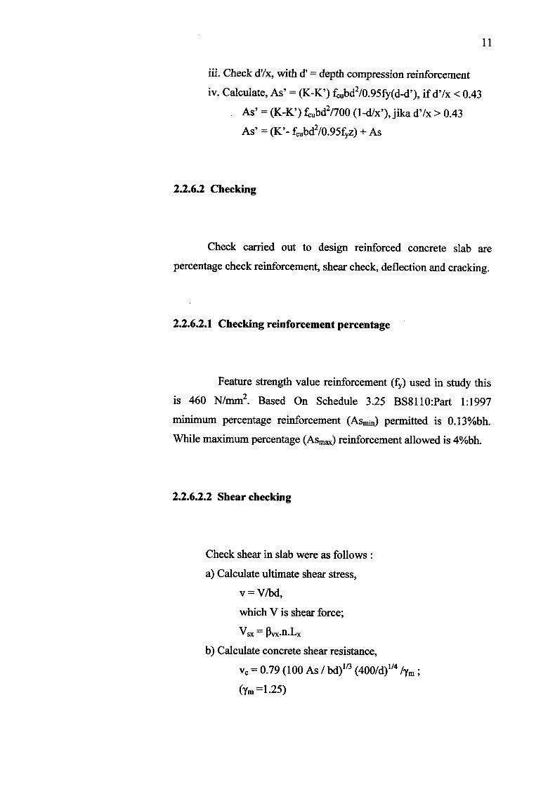
iii. Check d'/x, with d' = depth compression reinforcement
iv. Calculate, As' = (K-K') fbd2/0.95fy(d-d'), if d'/x <0.43
As' = (K-K') fbd2/70O (1-dlx'),jika d'Ix> 0.43
As' (K'- fbd2/0.95fz) + As
2.2.6.2 Checking
Check carried out to design reinforced concrete slab are
percentage check reinforcement, shear check, deflection and cracking.
2.2.6.2.1 Checking reinforcement percentage
Feature strength value reinforcement (fr) used in study this
is 460 N/mm2. Based On Schedule 3.25 BS8110:Part 1:1997
minimum percentage reinforcement (ASmjn) permitted is 0.13%bh.
While maximum percentage (ASm) reinforcement allowed is 40/obh.
2.2.6.2.2 Shear checking
Check shear in slab were as follows:
a) Calculate ultimate shear stress,
v = V/bd,
which V is shear force;
Vsx =
b) Calculate concrete shear resistance,
v = 0.79 (100 As / bd) 1 "3 (400/d)"4 /7m (Tm 1.25)
12
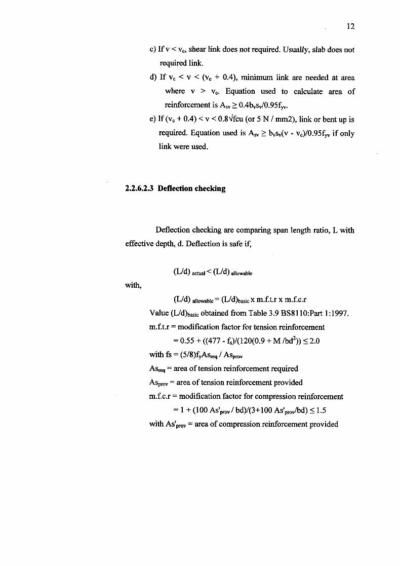
c) If v < v, shear link does not required. Usually, slab does not
required link.
d) If. v <v < (v + 0.4), minimum link are needed at area
where v > v. Equation used to calculate area of
reinforcement is As, ^: 0.4bs/0.95f.
e) If (v + 0.4) <v < 0.8Vfcu (or 5 N / mm2), link or bent up is
required. Equation used is As, ^: bs(v - v)/0.95f if only
link were used.
2.2.6.2.3 Deflection checking
Deflection checking are comparing span length ratio, L with
effective depth, d. Deflection is safe if,
(L/d) actual < (Lid) allowable
with,
(L/d) allowable = (L/d)bj x m.f.t.r x m.f.c.r
Value (L/d)bic obtained from Table 3.9 BS811 O:Part 1:1997.
m.f.t.r = modification factor for tension reinforcement
= 0.55 + ((477 - f)/(120(0.9 + M ibd2)) S 2.0
with fs = (5/8)fyASreq / ASprov
Asreq = area of tension reinforcement required
ASprov = area of tension reinforcement provided
m.f.c.r = modification factor for compression reinforcement
= 1 + (100 As'pmv/ bd)/(3+100 AS'prov/bd) S 1.5
With AS'prov = area of compression reinforcement provided
13
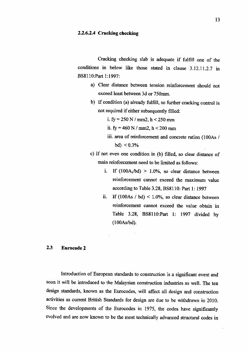
2.2.6.2.4 Cracking checking
Cracking checking slab is adequate if fulfill one of the
conditions in below like those stated in clause 3.12.11.2.7 in
BS811O:Part 1:1997:
a) Clear distance between tension reinforcement should not
exceed least between 3d or 750mm.
b) If condition (a) already fulfill, so further cracking control is
not required if either subsequently filled:
i.fy250N/mm2,h<250mm
ii. fy = 460N/mm2, h<200mm
iii. area of reinforcement and concrete ration (lOOAs /
bd) <0.3%
c) If not even one condition in (b) filled, so clear distance of
main reinforcement need to be limited as follows:
i. If (100A/bd) > 1.0%, so clear distance between
reinforcement cannot exceed the maximum value
according to Table 3.28, BS8 110: Part 1: 1997
ii. If (lOOAs / bd) < 1.0%, so clear distance between
reinforcement cannot exceed the value obtain in
Table 3.28, BS8110:Part 1: 1997 divided by
(1 OOAsfbd).
23 Eurocode 2
Introduction of European standards to construction is a significant event and
soon it will be introduced to the Malaysian construction industries as well. The ten
design standards, known as the Eurocodes, will affect all design and construction
activities as current British Standards for design are due to be withdrawn in 2010.
Since the developments of the Eurocodes in 1975, the codes have significantly
evolved and are now known to be the most technically advanced structural codes in

14
the world. These ten Eurocodes covers all the main structural materials (see Figure
2.3). These codes produced by the European Committee for Standardization (CEN),
will replace existing national standards in 28 countries.
Eurocode 2 is one of 10 Eurocodes that will form into a uniform process of
design. Eurocode 2 and EC2 are both abbreviations for BS EN 1992, Eurocode 2:
Design of concrete structures. Although there is a transition period, eventually
Eurocode 2 will replace all national codes dealing with the design of structural
concrete (such as BS8 110, BS 5400 in the UK).
BE EN 1 G4!: flIctUii sfty, tit( iSOMICeability and 4kribflfty
I11 1:] Antii1urQs (Atli" gju*rj
BE FN E EN 1&Eiwo,
BE EN 14 Ei 4 -.Campt. Design and dtfling
BE (N 19%, E1hI6 : Mn! BE EN iw4 9AWnUn
BE EN 1t'1, Fwecl. GotwiicL _________j and sIsmk
design
Figure 2.3: The Eurocodes
2.3.1 Principles of Eurocode 2
EN 1992 Eurocode 2: Design of concrete structures is of fundamental
importance to civil engineers given the predominance of concrete in civil
engineering construction. Ultimately Eurocode 2 will become the one design
code for all concrete structures. It will bring reinforced concrete design up-to-
date. The general basis for design of structures in reinforced and prestressed
concrete made with normal and lightweight concrete together with specific
rules given are mainly aimed at building structures as explained in the first
15
section of the first part of Eurocode 2. The new code will thus be a more
comprehensive document than its predecessor.
The scope of design in Eurocodes is similar to many current national
codes in Europe. The main chapters of the code deal with:
Basis of design
• Materials
• Durability
• Structural analysis
• Ultimate limit state
• Serviceability limit state
• Detailing of reinforcement
• Detailing of members
• Additional rules for precast elements and structures
• Lightweight aggregate concrete
• Plain concrete
It has been known that the design process will not change as a result
of using Eurocode 2. But there is a change of emphasis as Eurocode 2 is laid
out to deal with phenomena such as flexure, shear and deflection rather than
beams, slabs, column and foundation which are dealt with in BS81 10.
2.3.2 Aims and Purposes of Eurocode 2
Officially, the Eurocodes are intended to serve as reference
documents to act as a means of compliance of building and civil engineering
works. It also acts as a framework for drawing up harmonized technical
specifications for construction products. The aims and benefits of the