competitive concrete foundations for offshore wind turbines
TRANSCRIPT
COMPETITIVE CONCRETE FOUNDATIONS FOR
OFFSHORE WIND TURBINES
W Brook-Hart, PA Jackson, M Meyts, P Sayer
Gifford, Gifford, Gifford, Bierrum International
Key words: Offshore, wind energy, renewable energy, foundations, slipform, concrete, prestress
Abstract:
This paper presents aspects of a research project to develop competitive engineering solutions for concrete gravity base foundations. The project was funded by the UK Department of Trade and Industry / UK Dept for Business, Enterprise & Regulatory Reform’s Technology Programme (Collaborative Research and Development for Low Carbon Energy Technologies).
The need for much greater use of renewable energy is driving a substantial increase in the numbers of offshore wind farms in European waters, and in particular the UK is planning for up to 33GW of installed capacity by 2020, equivalent to over 6000 wind turbines of 5MW capacity.
The authors have developed a competitive design for concrete gravity base foundations, which can have important technical advantages for large turbines in greater water depths, as well as increasing the range of suppliers and contractors able to contribute to offshore developments.
The paper provides an overview of the production process, which provides a competitive solution for construction, transportation and installation. It focuses on the particular aspects of design and construction necessary to achieve a durable, reliable and sustainable solution for the offshore marine environment.
The use of prestressing is enabled by dense concrete with cement-replacing additives, the choice of prestressing system including passive anchors embedded within the concrete mass and the use of resilient grout to inject the prestress ducts. This enables a high degree of durability and fatigue resistance.
The structural concept has been developed to enable industrial production methods to obtain high Quality Control and high production rates. These include prefabricated formwork, slipform and templates to ensure the tight tolerances required for erection of the steel tower at the offshore location.
1. INTRODUCTION
1.1 Context
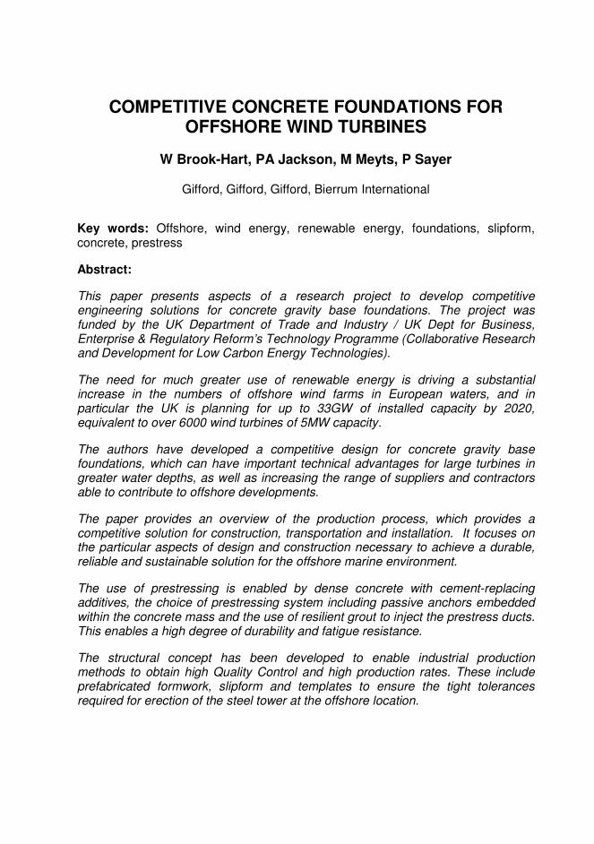
The Energy Policy for Europe sets a target of 20% of total energy consumption being supplied by renewable energy by 2020 to mitigate climate change and improve the security and cost of energy. A major part of this is to be provided by offshore wind farms and UK Government policy is to achieve up to 33GW of offshore wind capacity by 2020. This compares with about 0.5GW presently installed and it will thus require a great increase in the the capacity of the construction industry to supply and install offshore foundations for offshore wind farms. The trend is towards the use of larger turbines (3 to 5MW or more), installed in deeper water (20m or more), with greater wave exposure. This will require both innovation and adaptation of existing proven technologies and procurement methods, to build the foundations cost-effectively and reliably in a formidably challenging offshore environment.
Figure 1. Offshore Wind Turbine on Concrete Gravity Base Foundation
1.2 Competitive concrete foundations
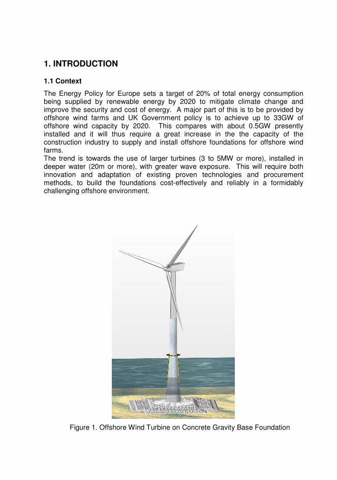
This paper presents aspects of a research project to develop competitive engineering solutions for concrete gravity base foundations. The project was funded by the UK Department of Trade and Industry / UK Dept for Business, Enterprise & Regulatory Reform’s Technology Programme (Collaborative Research and Development for Low Carbon Energy Technologies), and has been undertaken by a consortium including offshore wind farm developers, marine civil and structural engineers, naval architects, offshore specialists, concrete contractors and academic researchers. A previous study by Gifford for the Concrete Centre[1,2] established a number of potential advantages of concrete gravity base foundations for offshore wind turbines. The purpose of this collaborative study has been to address each stage of construction, transport, installation and eventual complete removal of the foundations, to achieve a well-integrated and sustainable approach, increasing reliability and controlling costs. Some features of the proposed approach are summarised below. Onshore construction The concrete gravity base foundations are to be built in an onshore construction yard, for efficient repetitive year-round production of concrete foundation base units, with close access to sheltered navigable water. Concrete is to be slipformed for speed of production, enabling conventional construction onshore by mainstream civil engineering contractors. The use of pre-stressed concrete will provide a structurally efficient design, with good fatigue resistance and excellent durability in the marine environment. Transport and installation A major challenge to offshore installation has been the practicality of handling the large concrete structures, and the availability and cost of vessels to do so. This study has created an innovative solution for transport and installation using dedicated Transport and Installation Barges (TIBs), along with conventional offshore support vessels. This offers a relatively inexpensive alternative to offshore crane vessels and jack-up platforms.
Figure 2. Transport and Installation Barge Carrying Concrete Foundation
2. CONCRETE GRAVITY BASE UNIT DESIGN
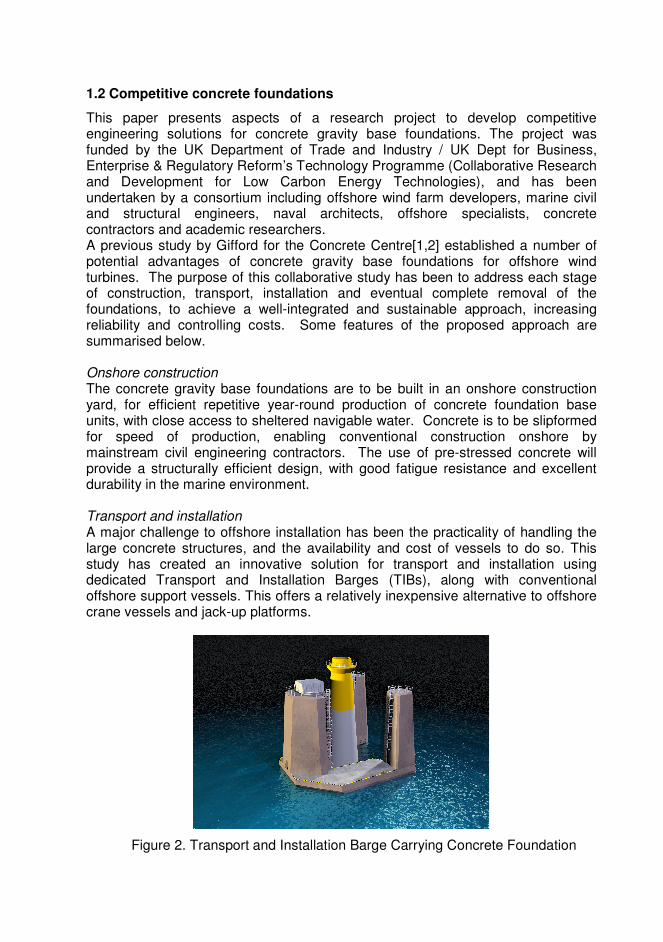
The concrete gravity base unit is a single structure of prestressed concrete. It comprises a hollow conical stem and a circular raft footing with continuous reinforcement of passive and prestressed steel. The dimension of the stem is chosen to provide the required anchoring for the tower of the turbine, with a circular layout of anchor bolts designed to resist the loads at the base of the tower from dead weight, wind, turbine vibrations etc. The stem has vertical prestress over its whole height from its top at the level of the anchor bolts to its connection to the raft footing. This prestress transfers the overturning bending moments to the raft. The dimension of the raft footing is determined by the overturning moment at the foot of the stem, and the allowable bearing pressures on the seabed. It is therefore site-specific: for deeper water, greater wind loads, more severe sea states and weaker seabed, a greater diameter is needed. However, the basic design of a circular raft stiffened by prestressed concrete radial ribs transferring the overturning moment from the foot of the stem to the seabed, remains the same for all applications.
Figure 3. Concrete Gravity Base Unit
The design has been analysed for a range of water depths, sea states and wind regimes. These have confirmed the robustness of the design, while highlighting the need for proper preparation of the seabed (for level, flatness) as well as implementation of scour protection around the footing after construction. Accidental events such as ship impact have been analysed. The concrete of the stem is robust to the impact of a ship, with little consequence on the long-term strength of the concrete. The design has been verified for fatigue loadings on the anchor bolts, on the concrete components and their reinforcement. An important parameter in the design of the base unit is its interface with the design of the Transport and Installation Barge (TIB). Following investigation of various configurations, the system of connections between the base of the TIB and the top of the raft footing was found to provide the best solution while maintaining facility of operation during placement.
3. CONCRETE DESIGN
Reinforced and prestressed concrete have successful track records in the marine environment. The longevity of the structure requires passive resistance to corrosion, infiltration of water and chemical deterioration. These are addressed by design of concrete materials, choice of injection grout for the prestress ducts, adequate cover for the passive reinforcement and attention to the methodology of construction to ensure that weak points are not introduced into the structure, which may initiate points of failure. Specific measures to enhance longevity of the concrete gravity base unit include the use of cement replacements such as Fly Ash or Granulated Ground Blast Furnace Slag. These enhance the durability of the concrete by improving the chloride resistance as well as facilitating construction under the favoured slipform process recommended for construction of the stem. A typical concrete mix for the slipformed stem will have a higher percentage of sand than standard to give a creamier mix that allows the slipform process to achieve a good finish and reduce the drag on the shutter. Concrete trials would be carried out prior to the operation starting, ideally by trying a small three metre high slipform section of equal wall thickness to that of the stem. This will give a good indication of setting times as well as strength and finish. The key to slipforming successfully is to have a consistent mix that behaves in a predictable way. The concrete is placed in layers, perhaps 200mm deep, around the perimeter of the slipform shutter. In order to move the shutter upwards all the concrete has to be in a similar setting condition. If one area is too green then it will slump out of the bottom of the shutter as the shutter moves upwards. The concrete mix must also be able to adjust its setting times in a known manner: this can be achieved by the addition of accelerators and retarders. The retarding effect is useful when the installation of rebar and prestressing ducts becomes congested and more time is needed to fix them before the shutter needs to move. However the amount of retarder must then be reduced gradually so that there is not a jump in the setting times of different layers. Similarly, if accelerators are used to speed up the setting times due to cold weather, this must be added in

increments to successive layers to avoid a situation where one layer is setting before the one below. If this happens there is a danger that the layer that has set will stick to the shutter. When the shutter subsequently moves it will probably tear of the concrete surface. The various mixes must be tested beforehand to give an indication of their performance. They should have a range of known properties so that as work proceeds the correct mix can be employed for a given set of circumstances. The integrity of the structures depends on the integrity of the prestressing tendons which are protected by grout. Well-publicised problems with grouted post-tensioning in bridges led to a ban on the system by the UK Highways Agency for several years. This prompted extensive work initially by the Concrete Society and later in a Brite Euram project led by Gifford[3]. Major changes to past practice have included use of watertight plastic ducts, development of proprietary pre bagged grout and new tests to determine the grout properties. All these advances would be used for these structures. For the long vertical tendons used, the bleed and segregation properties of the grout are particularly important since, with a 100m vertical duct, 1% bleed could result in a metre of strand in pure water. The vertical cylinder test developed in the Brite Euram project and adopted in a modified form in the EN, enables the properties of grout to be tested to ensure they are adequate including in this respect.
4. ONSHORE CONSTRUCTION
The concrete gravity base foundation design consists of two main elements, namely the base and the stem. The next generation of wind farms will typically require 50 to 100 foundation units. Construction will therefore require a purpose made production facility to build the units efficiently, repetitively and to high quality. The design of the facility will include a landing to receive materials (aggregates, sand, cement and reinforcement) as well as a launching ramp or load-out quay.
FFigure 4. Building Yard and Load Out Quay
The facility will include concrete batching plant, craneage and reinforcement fabrication yards. The units to be constructed will be phased so that there may be
up to six being constructed at one time. Each one will be at a different stage of completion in order to achieve the most efficient use of resources. A yard will be set up to prefabricate the reinforcement cages as much as possible. These sections can then be lifted over and placed on the construction slab ready for the start of the construction. As part of the reinforcement fix, the prestressing ducts will be tied into the cage and the ends and joints securely sealed. The shutters to form the ribs will be designed with speed and re-use in mind. A steel shutter is likely. The sections will be made up into large units and lifted into place around the reinforcement. Large steel units will be quicker to strip and reset. A complete set of ribs for one base will be set and cast using pumped concrete. After striking the formwork from the ribs, the infill panels will be completed in between the ribs to form a complete base. The base prestressing can commence once the concrete has cured and achieved sufficient strength. It is envisaged that this can take place whilst the slipform shutter for the stem is being erected on the base. The prestressing for the bases is in the horizontal plane. A system for supporting the tendons during the feeding in operations will have to be employed. After stressing the ducts are pumped full of grout. This has to cure before the base can be lifted. The slip form process for the stem consists of the sliding shutter connected to a three deck rig climbing on 20mm jackrods. The jackrods are positioned in the middle of the wall and are recovered at the end of the slipform. Concrete will be transported to the top deck via a winch arrangement up the middle of the stem and out at the top deck where it will be transported by wheelbarrow to the shutter. Reinforcement will be fixed from the second deck having been taken up by hoist to the top deck and evenly distributed around the perimeter. When it is required for fixing it will be handed down to the deck below. The prestress in the stem will be vertical only and will be installed by including ducts in the slipform and placing the tendons into the ducts post slipform. It is important to use a duct system that is not prone to damage or leakage. The ducts will be placed in position as the slipform creeps upwards with sections being joined on as work proceeds. Any mistakes here will result in the duct being blocked and probably having to be abandoned. After the stressing process has been completed the ducts are grouted. When each unit is cast it will be raised up and loaded on a series of wheeled transporters and taken to the launch position. The cycle time for each unit’s construction controls the need for the number of units in production at any time. As one process finishes, the same process needs to commence on the next unit. The number of building bays available to the project must be matched to the anticipated production. Six bays will be the likely number to allow the base and stem to be constructed, cured, stressed and moved whilst keeping all the trades employed, to produce one unit per week. The facility can be scaled up for higher production rates.
5. CONCLUSION
The study has produced an integrated design solution for construction, transportation, installation, operation and eventual complete removal of concrete gravity base foundations for offshore wind turbines. It combines efficient repetitive year-round onshore production and seasonal offshore delivery of units. The onshore construction process, with use of slipformed concrete for speed of production, enables conventional construction onshore by mainstream civil engineering contractors. The use of pre-stressed concrete results in a structurally efficient design with good fatigue resistance and durability in the marine environment. The delivery of the gravity base units to the wind farm using the innovative and relatively low-cost Transport and Installation Barge (TIB) avoids reliance on offshore heavy lift vessels or jack-ups for foundation installation. The relatively quick placement of the foundations on the seabed minimises the weather window needed for installation.
Development of a competitive concrete gravity base alternative to steel foundations will bring more resources to the supply chain, which will be essential to achieving the UK government’s target of up to 33GW capacity of offshore wind energy by 2020.
REFERENCES
[1] Tricklebank A. Halberstadt P. & Magee B. 2007. Concrete towers for Onshore
and Offshore Wind Farms – Conceptual Studies. London. Concrete Centre. [2] Tricklebank A. 2006. Concrete towers – an emerging competitor. London.
British Wind Energy Association Offshore Wind Conference. [3] Tilly GP Improved quality assurance & methods of grouting post-tensioned tendons Final Project report Brite/Euram contract BRPR-CT950099-BE95-1675 December 1999.