computational aerodynamic analysis of three- dimensional ... · computational aerodynamic analysis...
TRANSCRIPT
National Aeronautics and Space Administration
www.nasa.gov
Computational Aerodynamic Analysis of Three-dimensional Ice Shapes on a NACA 23012 Airfoil
GaRam Jun (University of Michigan)Daniel Oliden (Arizona State University)
Mark Potapczuk (NASA Glenn Research Center)Jen-Ching Tsao (Ohio Aerospace Institute)
6th AIAA Atmospheric and Space Environments ConferenceAtlanta, GA June 16-20, 2014
https://ntrs.nasa.gov/search.jsp?R=20150000895 2018-06-13T11:01:24+00:00Z

National Aeronautics and Space Administration
www.nasa.gov
Overview
• Background• Motivation
– Ice Accretion Shapes– Workflow
• Approach– Grid Generation– CFD
• Results• Future Work

National Aeronautics and Space Administration
www.nasa.gov
Background
-4 -2 0 2 4 6 8 100
0.01
0.02
0.03
0.04
0.05
0.06
0.07
0.08
0.09
0.1
Runback
Glaze
Clean
Angle of Attack, deg
Dra
g C
oeffi
cien
t, C
d
-4 0 4 8 12 16 200
0.2
0.4
0.6
0.8
1
1.2
1.4
1.6
Angle of Attack, deg
Lift
Coe
ffici
ent,
Cl
Runback
Glaze
Rime
Clean
Rime

National Aeronautics and Space Administration
www.nasa.gov
Background• To-date CFD analysis has been performed on, 2D cross-
sections, 3D extrusions of 2D cross-sections, and 3D ice shapes generated by ice accretion codes

National Aeronautics and Space Administration
www.nasa.gov
Motivation
• Complex 3D ice shape geometry data can now be collected– In-situ laser scans of ice accretion shapes– CAT scans have also been performed– Complete ice shape documentation, including surface
roughness elements
• How good is good enough?– What level of ice shape detail must be simulated by ice
accretion codes?– Detailed analysis of the aerodynamics and heat transfer
mechanisms at the ice-liquid-air interface can shed light on the parameters of importance

National Aeronautics and Space Administration
www.nasa.gov
Ice Accretion Shapes
• Types of ice accretion– Rime

National Aeronautics and Space Administration
www.nasa.gov
Ice Accretion Shapes
• Types of ice accretion– Glaze

National Aeronautics and Space Administration
www.nasa.gov
Workflow
Ice Shape Scanned in IRT
Ice Shape Processed with Geomagic
Ice Shape Grid Built in Pointwise
Aerodynamic Analysis with NCC
Plotting and Visualization with Tecplot

National Aeronautics and Space Administration
www.nasa.gov
Approach (Grid Generation)
Geomagic
Commercial software used to create watertight surface from scanned point cloud data
Lee, S., Broeren, A. P., Addy, H. E., Jr., Sills, R., and Pifer, E. M., “Development of 3-D Ice Accretion Measurement Method,” NASA/TM-2012-217702, AIAA Paper-2012-2938, 2012

National Aeronautics and Space Administration
www.nasa.gov
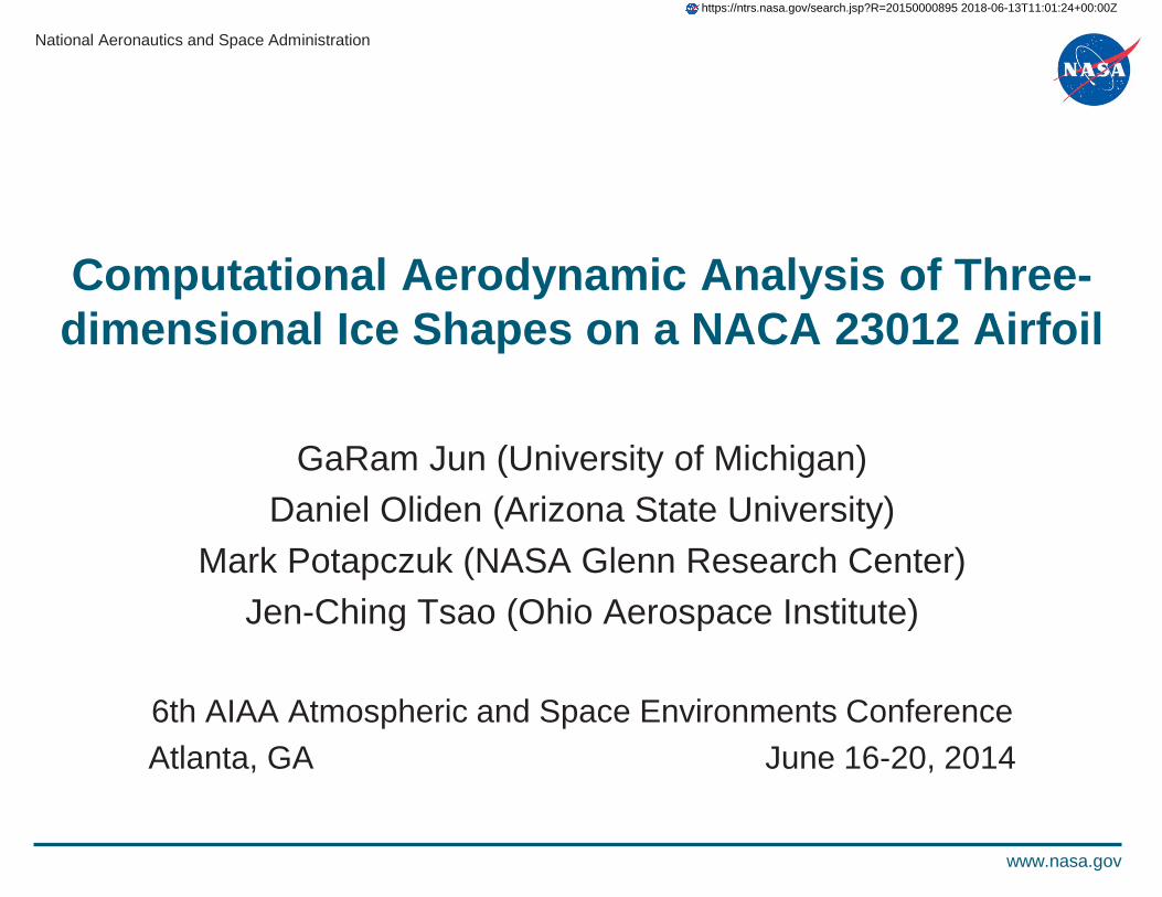
Pointwise
Commercial software used to import ice shape geometry data and create grid for CFD analysis
1. Import Geometry• Database• Surface Grid
Approach (Grid Generation)
National Aeronautics and Space Administration
www.nasa.gov
Approach (Grid Generation)Pointwise
1. Import Geometry2. Create Surface Grid - Rime
National Aeronautics and Space Administration
www.nasa.gov
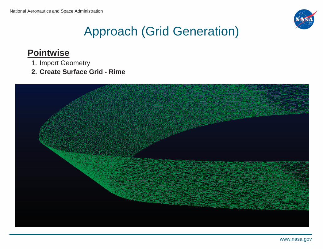
Approach (Grid Generation)Pointwise
1. Import Geometry2. Create Surface Grid - Horn
National Aeronautics and Space Administration
www.nasa.gov
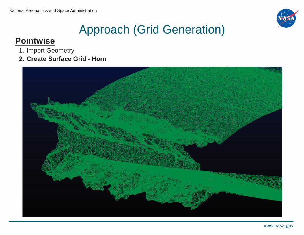
Approach (Grid Generation)Pointwise
1. Import Geometry2. Create Surface Grid3. Create Volume Grid - Rime
National Aeronautics and Space Administration
www.nasa.gov
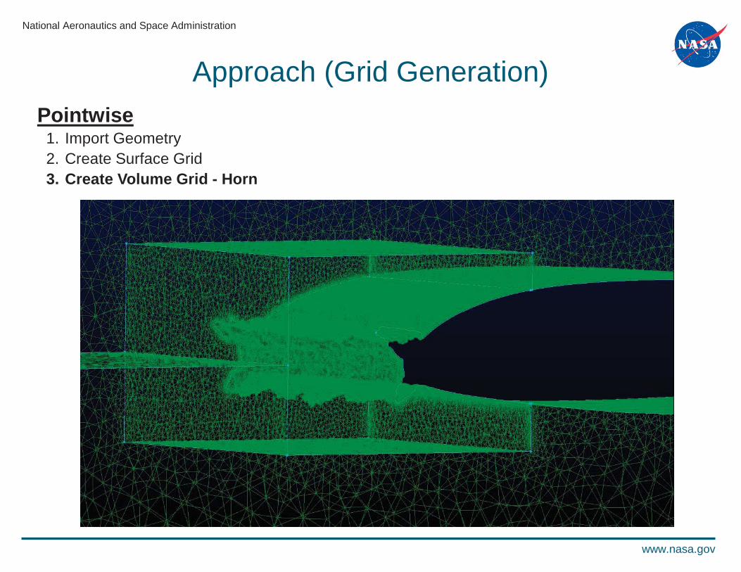
Approach (Grid Generation)Pointwise
1. Import Geometry2. Create Surface Grid3. Create Volume Grid - Horn
National Aeronautics and Space Administration
www.nasa.gov
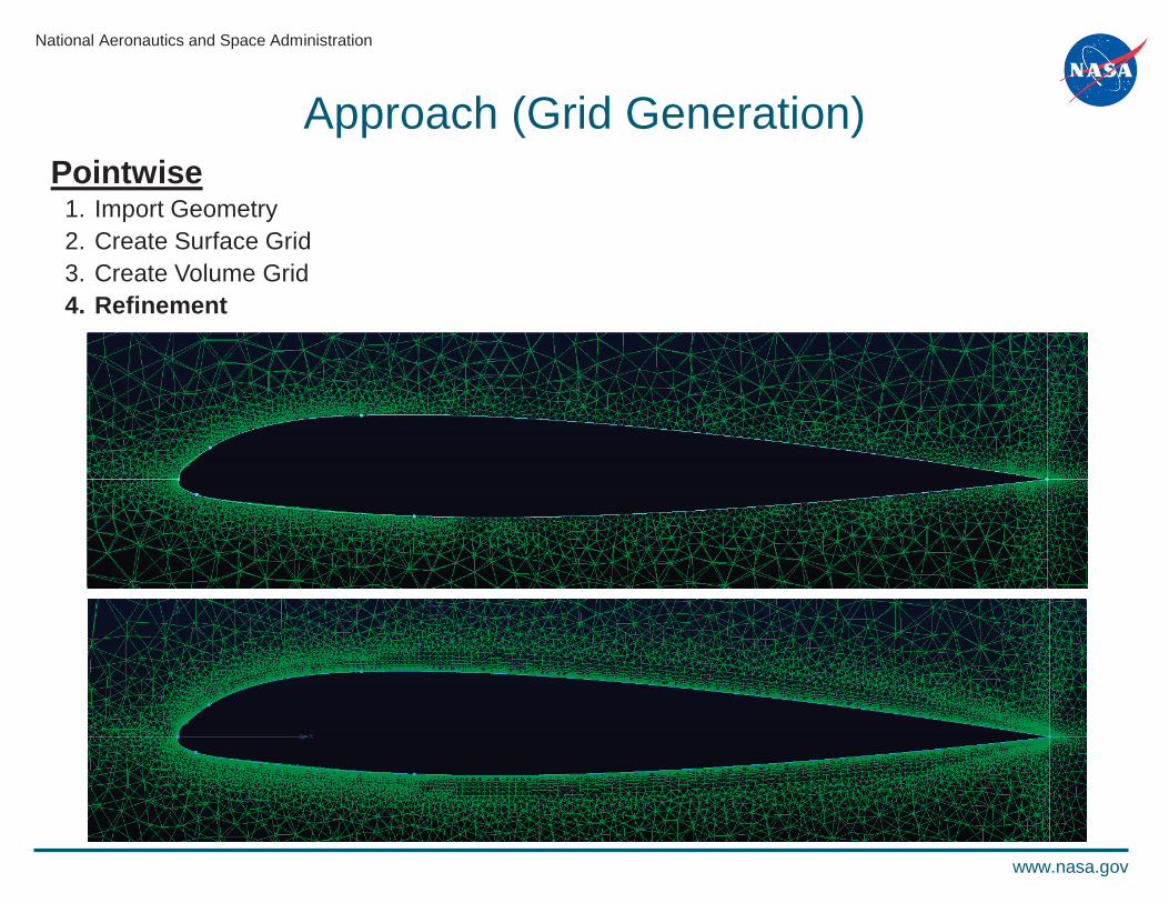
Approach (Grid Generation)Pointwise
1. Import Geometry2. Create Surface Grid3. Create Volume Grid4. Refinement
National Aeronautics and Space Administration
www.nasa.gov
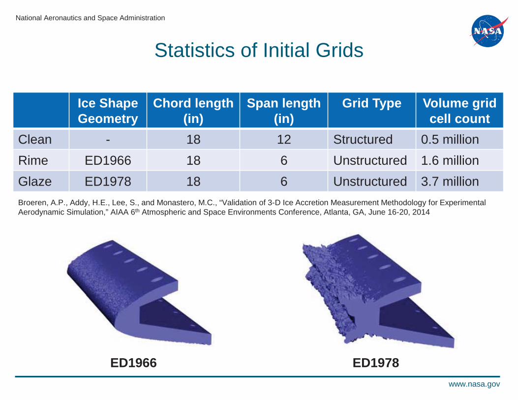
Statistics of Initial Grids
Ice Shape Geometry
Chord length(in)
Span length(in)
Grid Type Volume gridcell count
Clean - 18 12 Structured 0.5 millionRime ED1966 18 6 Unstructured 1.6 millionGlaze ED1978 18 6 Unstructured 3.7 million
ED1966 ED1978
Broeren, A.P., Addy, H.E., Lee, S., and Monastero, M.C., “Validation of 3-D Ice Accretion Measurement Methodology for Experimental Aerodynamic Simulation,” AIAA 6th Atmospheric and Space Environments Conference, Atlanta, GA, June 16-20, 2014

National Aeronautics and Space Administration
www.nasa.gov
National Combustion Code (NCC)
• Solver – Finite-volume– Explicit, four-stage Runge-Kutta integration algorithm– RANS, URANS
• Turbulence – model– higher order, non-linear method– Partially Resolved Numerical Simulation (PRNS)
• Parallel Computing– Parallel Virtual Machine (PVM)– Message Passing Interface (MPI)
Liu, N.-S. and Shih, T.-H., “Turbulent Modeling for Very Large-Eddy Simulation,” AIAA Journal, Vol. 44, No. 4, April 2006

National Aeronautics and Space Administration
www.nasa.gov
Domain Conditions
• Boundary Conditions– Velocity Inlet– Pressure Outlet– No-slip Airfoil Wall– Periodic Side Walls
• Freestream ConditionsM = 0.10, 0.18Re = 1.0x10⁶, 1.8x10⁶
P = 98,595 [Pa]T = 294.3 [K]
= 0° to 10°

National Aeronautics and Space Administration
www.nasa.gov
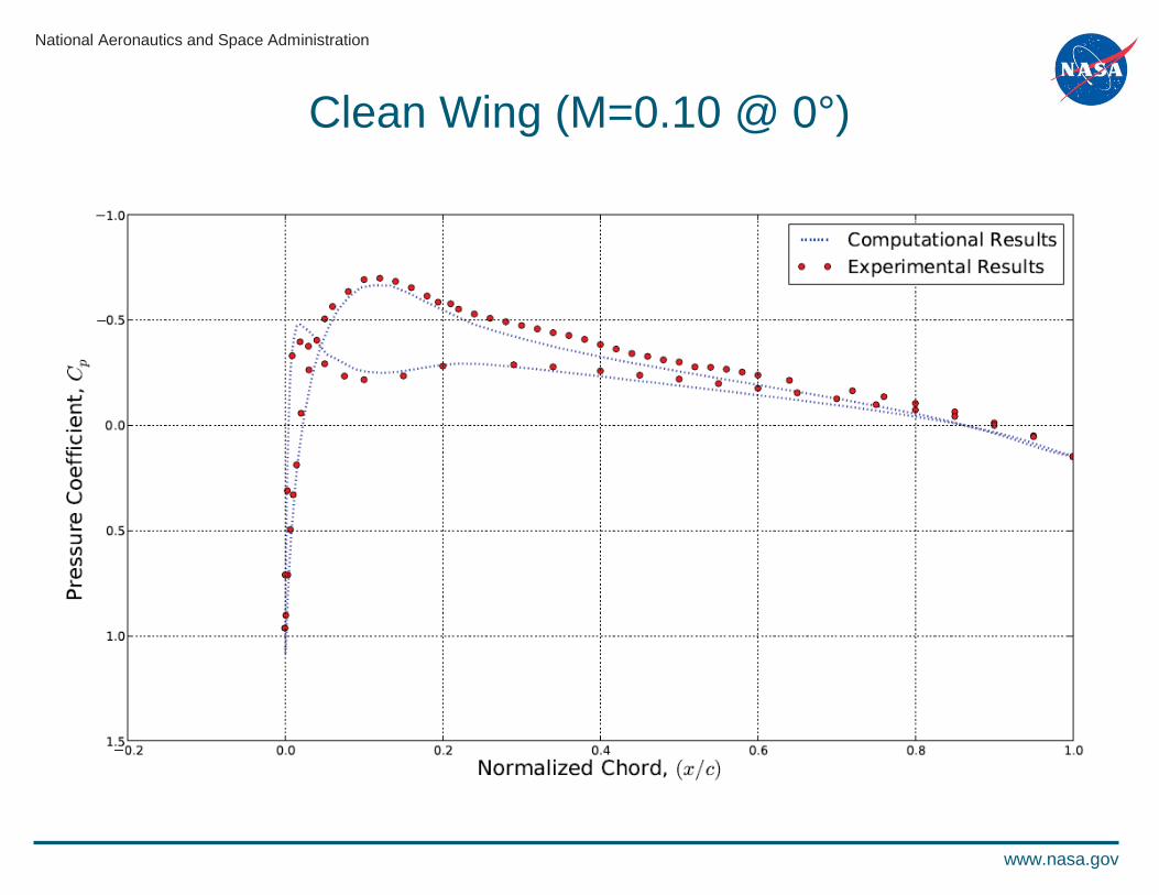
Clean Wing (M=0.10 @ 0°)
National Aeronautics and Space Administration
www.nasa.gov
Clean Wing (M=0.10 @ 0°)

National Aeronautics and Space Administration
www.nasa.gov
Clean Wing (M=0.10 @ 0°)Other CFD Solvers

National Aeronautics and Space Administration
www.nasa.gov
Clean Wing (M=0.10 @ 0°)Other CFD Solvers

National Aeronautics and Space Administration
www.nasa.gov
Clean Wing CL Curve (M=0.10)

National Aeronautics and Space Administration
www.nasa.gov
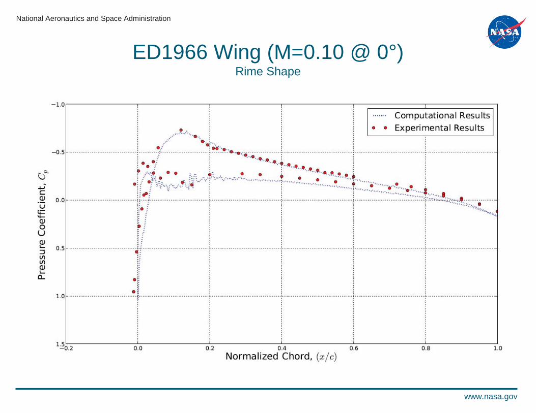
ED1966 Wing (M=0.10 @ 0°)Rime Shape
National Aeronautics and Space Administration
www.nasa.gov
ED1966 Wing (M=0.10 @ 0°)Rime Shape

National Aeronautics and Space Administration
www.nasa.gov
ED1966 Wing Lift Coefficient ResultsRime Shape
Re = 1.0x10⁶, M = 0.1 Re = 1.8x10⁶, M = 0.18
• Results suggest that viscous effects play a role for the rime ice case, consistent with expectations
• Results from a single instantaneous pressure profile, used in the computation, need to be replaced with time averaged and spatially integrated results

National Aeronautics and Space Administration
www.nasa.gov
ED1978 Wing (M=0.18 @ 0°)Glaze shape

National Aeronautics and Space Administration
www.nasa.gov
ED1978 Wing (M=0.18 @ 0°)Glaze Shape

National Aeronautics and Space Administration
www.nasa.gov
Future Work• Detailed examination of solutions
– Both ice shapes (ED1966 and ED1978)Variations in flow field results across the spanTime averaging of unsteady resultsSpatial integration across the spanGrid resolution studiesTurbulence models
– Glaze ice shape (ED1978)Investigate cause of pressure fluctuations near leading edge
• Parametric study of mesh quality– Establish minimum amount of grid points along airfoil surface
• Perform detailed analysis of ice surface roughness region• Develop post-processing modules for NCC to calculate
standard external aerodynamic parameters
National Aeronautics and Space Administration
www.nasa.gov
Thank You!
Questions?