computer architecture (p175b125) assoc.prof. stasys maciulevičius computer dept....
TRANSCRIPT


©S.Maciulevičius 22009-2013
Virtual memory
Modern computers can simultaneously run several programs (in parallel or pseudoparallel mode)
Each such program (process) has a separate code and data area
The mechanism that provides for more processes run simultaneously, sharing the memory correctly and correct addresing of information, transforming logical addresses to physical addresses is called Virtual
Memory

©S.Maciulevičius 32009-2013
Virtual memory
Moreover, the virtual memory ensure that the necessary for process information (program code and data) at the appropriate time would be loaded in the main memory, protects the process memory space from other processes
Virtual memory in physical point of view - the main memory plus part of the external memory, together with the tools for address transforming and information interchanging between these levels
Virtual memory in logical point of view - extended memory space with contiguous addressing

©S.Maciulevičius 42009-2013
Virtual memory
There are two main principles used in realization of virtual memory:
1) Segmentation - an application's virtual address space is divided into variable-length segments. A virtual address consists of a segment number and an offset within the segment. Task may have several segments – code (program), data, stack.
2) Paging – an application's virtual address space is divided into fixed sized pages; a page is a block of contiguous virtual memory addresses, usually at least 4Kbytes in size. The pages do not have to be contiguous in memory

©S.Maciulevičius 52009-2013
Main and external memory
CPU reg.
Swap insegment
(page)
Cache
Main memory
External memory
Swap outsegment
(page)

©S.Maciulevičius 62009-2013
Segmented virtual memory
Op. system
1’st process
2’nd process
3’rd process
4’th process
5’th process
Op. system
2’nd process
3’rd process
4’th process
5’th process
Op. system
2’nd process
3’rd process
5’th process
Op. system
2’nd process
3’rd process
6’th process
5’th process

©S.Maciulevičius 72009-2013
Segmenting
Segment No. Byte address
31 24 23 0
Segm.No. 32-bit base
0 20000H 1 4F000H 2 8000H … ….
Memory
2 segm
0 segm.
1 segm.
8000
Segment table
4F000
20000248

©S.Maciulevičius 82009-2013
Simple mechanism of segmentation
Stack length
Data length
Program length
MUX
Stack base
Data base
Program base
MUX
Page faultCompa-rator
Offset
Segment
Sum-mator Physical
address

©S.Maciulevičius 92009-2013
Segmentation principles in IA-32
Selector Effective address
15 0 31 0
Descriptor table
Segment descriptor +Base address
Linear (physical) address31 0

©S.Maciulevičius 102009-2013
Segmentation mechanism in IA-32
In IA-32 architecture segmentation is supported by folowing tools:• mechanism for calculation of physical address• segment descriptor tables:
• local descriptor table (LDT)• global descriptor table (GDT)• interrupt descriptor table (IDT)
• privilegy system
Each table has assigned to it the processor register, which holds:• 16-bit limit (size of table)• 32-bit base address (table location in memory)

©S.Maciulevičius 112009-2013
Address spaces in IA-32
IA-32 architecture has three such address spaces:• logical address space; logical (or virtual) address
consists of two integers: a 16-bit segment selector and a 32-bit offset; space size is 214 selectors 4 GB = 64 TB
• linear address space; linear address appears on the output of segmentation unit, as result of logical address translation;
• physical address space; physical address appears on the output of paging unit; in case when paging is not used, physical address equals to linear address; this address (BE7-BE0 bits and A31-A3) goas to main memory

©S.Maciulevičius 122009-2013
Simple mechanism of paging
Page table
Logical page number Byte offset
Page frame number Byte offset
Protection bits

©S.Maciulevičius 132009-2013
Segmentation with paging in IA-32
Selector Effective address (offset)
15 0 31 0
Segmentation unit
Physical address31 0
Descriptor’s index
Paging unit
(optional)
14
32
32
32
Linear address

©S.Maciulevičius 142009-2013
Segmentation mechanism in IA-32

©S.Maciulevičius 152009-2013
Paging in IA-32
Page table
Directory Page No. Byte offset
Linear address
Page directory
PDE
PTE
Page (4 KB)
Target10
10 12
CR3 (PDBR)Control register(Page Directory Phys. Base Address)

©S.Maciulevičius 162009-2013
Address translation
Transformation of virtual address to physical is address translation.
The problem - the extra step – access to page table. How to speed up the memory access?
1. To store whole page table in processor - is unrealistic because the page table takes a lot of place - megabytes. For example, if the page size is 4 KB, a 4 GB of memory takes 4 GB / 4 KB = 1024 K pages!
2. To store part of page table in special cache in
processor. Each entry in this cache ensure fast access even to 1000 words

©S.Maciulevičius 172009-2013
Translation lookaside buffer (TLB)
Page
table
Logical page number Byte offset
Page frame number Byte offset
TLB
ORPage not in main memory
Effective address from CPU
Miss
Load TLB
Hit
Page swap with hard disc
Physical address to main memory

©S.Maciulevičius 182009-2013
TLB and cache
Physical address
Tag
Byte No.
Hit
Hit
Hit
Data line
Logical page number Byte offset
Cache
Effective address
=?
=?
Byte
TLB
Index Index

©S.Maciulevičius 192009-2013
Memory management unit
A memory management unit (MMU) is a computer hardware component responsible for handling accesses to memory requested by the CPU
Its functions include:• translation of virtual addresses to physical addresses
(i.e., virtual memory management)• memory protection• cache control• bus arbitration, and, in simpler computer architectures
(especially 8-bit systems)• bank switching

©S.Maciulevičius 202009-2013
AMD K7 microarchitecture

©S.Maciulevičius 212009-2013
Parity checking
A parity checking refers to the use of parity bits to check that data has been writted and readed accurately
The parity bit is added to every data unit (typically byte)
The parity bit for each unit is set so that: unit has either an odd number or unit has an even number of set bits

©S.Maciulevičius 222009-2013
Parity checking
k = b0 b1 … b7 ork = 1 b0 b1 … b7
0 1 0 1 0 1 1 0 k
Data bus
Error
Data bus
Usually k=n/8
n
k
k
n
Address bus
1 1
Data
AR bytes DR
generating parity bits / checking
n
m Parity bits

©S.Maciulevičius 232009-2013
Error-checking and correcting
Hamming code: a error-correcting code, can detect up to two simultaneous bit errors, and correct single-bit errors
Code length usually is k=log2n + 1;
With additional parity - k=log2n + 2Data bus
Error
n
k
k
n
Address bus
1 1
Data
AR bytes DR
Generating of Hamming
code
km ECC bits
Hamming check Error
Correc-tion
k
nn

©S.Maciulevičius 242009-2013
Hamming codeBit Binary Contr. Data
12 1 1 0 0 D8 11 1 0 1 1 D7 10 1 0 1 0 D6 9 1 0 0 1 D5 8 1 0 0 0 K8 7 0 1 1 1 D4 6 0 1 1 0 D3 5 0 1 0 1 D2 4 0 1 0 0 K4 3 0 0 1 1 D1 2 0 0 1 0 K2 1 0 0 0 1 K1
Hamming code detects up to two simultaneous bit errors, and corrects single-bit errors

©S.Maciulevičius 252009-2013
Generating of Hamming code
K1 = D1 D2 D4 D5 D7K2 = D1 D3 D4 D6 D7K4 = D2 D3 D4 D8K8 = D5 D6 D7 D8
Let data byte is 00111001, bit D1 – at right. Then:K1 = 1 0 1 1 0 = 1K2 = 1 0 1 1 0 = 1K4 = 0 0 1 0 = 1K8 = 1 1 0 0 = 0
Data byte is saved im memory with control bits:
001101001111

©S.Maciulevičius 262009-2013
Error correction
Let error occus, e.g., instead:001101001111
we have001101101111
Calculate Hamming code:K1 = 1 0 1 1 0 = 1K2 = 1 1 1 1 0 = 0K4 = 0 1 1 0 = 0K8 = 1 1 0 0 = 0
Use sum mod2: K8 K4 K2 K1
0 1 1 1 0 0 0 1 0 1 1 0 – this is number of fault bit

©S.Maciulevičius 272009-2013
Error correction: redundancy
Single error correction
Single error correction,
double error detection
Data bits
ECC bits
Redun-dancy, %
ECC bits Redundancy, %
8 4 50,00 5 62,50
16 5 31,25 6 37,50
32 6 18,75 7 21,88
64 7 10,4 8 12,50
128 8 6,25 9 7,03
256 9 3,52 10 3,91

©S.Maciulevičius 282009-2013
External memory
As long-term storage in computers are used:
hard drives CD-ROM, CDs (optical compact discs) DVDs flash memory floppy disks (outdated) strimmers.
©S.Maciulevičius 292009-2013
External memory

©S.Maciulevičius 302009-2013
External memory
Access modes: direct access sequential access
Parameters: capacity access time data transfer spped relative price

©S.Maciulevičius 312009-2013
First HD
IBM announced the IBM 350 storage unit as a component of the RAMAC 305 computer system on September 13, 1956
Assembled with covers, the 350 was 60 inches long, 68 inches high and 29 inches deep
It was configured with 50 magnetic disks containing 50,000 sectors, each of which held 100 alphanumeric characters, for a capacity of 5 million characters

©S.Maciulevičius 322009-2013
First HD
• 50 platters• 1 head

©S.Maciulevičius 332009-2013
First HD
Disks rotated at 1,200 rpm ; tracks (20 to the inch) were recorded at up to 100 bits per inch, and typical head-to-disk spacing was 800 microinches
The execution of a "seek" instruction positioned a read-write head to the track that contained the desired sector and selected the sector for a later read or write operation
Seek time averaged about 600 milliseconds

©S.Maciulevičius 342009-2013
Hard disk drive

©S.Maciulevičius 352009-2013
Hard disk drive
Platters vary in size and hard disk drives come in two form factors, 5.25in or 3.5in
Typically two or three or more platters are stacked on top of each other with a common spindle
Tthe head flies a fraction of a millimetre above the disk. On early hard disk drives this distance was around 0.2mm. In modern-day drives this has been reduced to 0.07mm or less
There's a read/write head for each side of each platter, mounted on arms

©S.Maciulevičius 362009-2013
Hard disk drive
The disk controller controls the drive's servo-motors and translates the fluctuating voltages from the head into digital data for the CPU
More often than not, the next set of data to be read is sequentially located on the disk. For this reason, hard drives contain between 256KB and 8MB of cache buffer in which to store all the information in a sector or cylinder in case it's needed. This is very effective in speeding up both throughput and access times

©S.Maciulevičius 372009-2013
Technical specifications
Capacity: Amount of data which can be stored on a hard drive
Transfer rate: Quantity of data which can be read or written from the disk per unit of time. It is expressed in bits per second (Mb/s)
Rotational speed: The speed at which the platters turn, expressed in rotations per minute (rpm for short). Hard drive speeds are on the order of 7200 to 15000 rpm. The faster a drive rotates, the higher its transfer rate. On the other hand, a hard drive which rotates quickly tends to be louder and heats up more easily

©S.Maciulevičius 382009-2013
Technical specifications Latency (also called rotational delay): The length
of time that passes between the moment when the disk finds the track and the moment it finds the data
Average access time: Average amount of time it takes the read head to find the right track and access the data. In other words, it represents the average length of time it takes the disk to provide data after having received the order to do so. It must be as short as possible
Radial density: number of tracks per inch (tpi). Linear density: number of bits per inch (bpi) on a given track. Surface density: ratio between the linear density and radial density
(expressed in bits per square inch).

©S.Maciulevičius 392009-2013
Technical specifications
Cache memory: Amound of memory located on the hard drive. Cache memory is used to store the drive's most frequently-accessed data, in order to improve overall performance
Interface: the connections used by the hard drive. The main hard drive interfaces are IDE/ATA, SATA, SCSI

©S.Maciulevičius 402009-2013
Information on disk

©S.Maciulevičius 412009-2013
Information on disk
The data is organised in concentric circles called "tracks"
The tracks are separated into areas called sectors, containing data (generally at least 512 octets per sector)
The term cylinder refers to all data found on the same track of different platters
The term clusters (also called allocation units) refers to minimum area that a file can take up on the hard drive

©S.Maciulevičius 422009-2013
Hard disk
Formatted and unformatted disk capacity
Capacity = Number_of_cylinders Number_of_surfaces
Number_of_sectors/cilinder sector_size
Modern disk capacity is at least 500 GB, advanced disks even reach 4 TB

©S.Maciulevičius 432009-2013
Hard disk
Access time depends on the following parameters:
cylinder seek time delay on the rotation transfer time
Information transmission time depends on: recording density and disk rotational speed

©S.Maciulevičius 442009-2013
Old disk - MD Maxtor 33073H3 Capacity 30 GB
Integrated interface ATA-5 / Ultra ATA/100
Buffer size/ type 2 MB SDRAM
Surfaces / Heads 3
Platters 2
Arreal density 14.7 Gb / sq. in. max
Track density 34 000 tpi
Linear density 354 - 431 kb/colyje
Bytes per sector/ Block 512
Sectors in track 373 - 746
Sectors in disk 60 032 448
©S.Maciulevičius 452009-2013
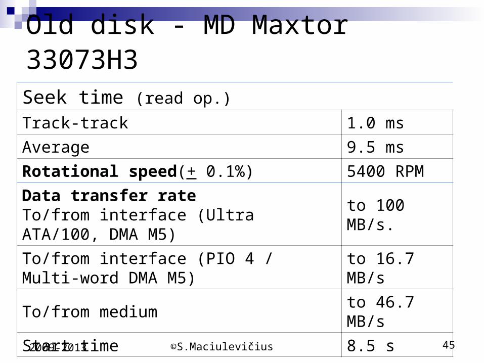
Old disk - MD Maxtor 33073H3
Seek time (read op.)
Track-track 1.0 ms
Average 9.5 ms
Rotational speed(+ 0.1%) 5400 RPM
Data transfer rate To/from interface (Ultra ATA/100, DMA M5)
to 100 MB/s.
To/from interface (PIO 4 / Multi-word DMA M5)
to 16.7 MB/s
To/from medium to 46.7 MB/s
Start time 8.5 s

©S.Maciulevičius 462009-2013
Recording methods
Traditional recording method –horizontal recording:
N S N S S N S N N S S N N S
Now a new recording method is in use – vertical (perpendicular) recording. The bits are in a vertical arrangement instead of horizontal in order to take up less space. By 2010, perpendicular densities are expected to exceed 500 Gb/sq. in.
N
S
S
N
S
N
N
S
S
N
S
N
S
N
N
S
S
N
N
S

©S.Maciulevičius 472009-2013
Disk density
Disk Density is measured and is also called areal density
Now how is this density calculated? For the most part the density we measure in Bit per Inch (BPI) and track per inch (TPI)
When we multiply the TPI and BPI we get areal density
RAMAC had an areal density of 2,000 bit/in²

©S.Maciulevičius 482009-2013
Disk density - 2008
In 2012 the highest areal density was around 625Gb/inch2. HDD areal densities measuring data-storage capacities are
projected to climb to a maximum 1800Gb/inch2 per platter by 2016, up from 744Gb/inch2 in 2011, as shown in the figure below
This means that from 2011 to 2016, the five-year compound annual growth rate (CAGR) for HDD areal densities will be equivalent to 19%
For this year, HDD areal densities are estimated to reach 780Gb/inch2 per platter, and then rise to 900Gb/inch2 next year.

©S.Maciulevičius 492009-2013
Disk density

©S.Maciulevičius 502009-2013
Disk capacity

©S.Maciulevičius 512009-2013
Flash memory
Flash memory refers to a particular type of EEPROM (Electronically Erasable Programmable Read Only Memory). It is a memory chip that maintains stored information without requiring a power source
Flash memory differs from EEPROM in that EEPROM erases its content one byte at a time. This makes it slow to update. Flash memory can erase its data in entire blocks, making it a preferable technology for applications that require frequent updating of large amounts of data

©S.Maciulevičius 522009-2013
Flash memory
Flash memory combines several useful features:
high packing density (the cell is 30% smaller than the DRAM)
maintaining stored information without requiring a
power supply erasing and recording information using electrical
signals low energy consumption high reliability and low price

©S.Maciulevičius 532009-2013
Flash memory
Flash memory is used primarily as: rarely rewritten (eg, BIOS) memory compact exchangeable memory in computers (USB
keys) compact exchangeable memory in PDAs, digital
cameras, digital audio players etc.
E.g., Kingston DataTraveler 200 is 32GB-128GB capacity
(DataTraveler 300 – 256GB), has 20MB/sec read, 10MB/sec write speed
DataTraveler Vault has 256-AES hardware-based encryption, 2GB-32GB capacity

©S.Maciulevičius 542009-2013
Solid state memory
Solid state memory or a solid state drive (SSD) is a device that uses no moving parts to store data
The first ferrite memory SSD devices, or auxiliary memory units as they were called at the time, emerged during the era of vacuum tube computers
In the 1970s and 1980s, SSDs were implemented in semiconductor memory for early supercomputers of IBM, Amdahl and Cray; however, the high price of the SSDs made them quite seldom used
RAM "disks" were popular as boot media in the 1980s when hard drives were expensive, floppy drives were slow

©S.Maciulevičius 552009-2013
Solid state memory
2004: Texas Memory Systems' RamSan-325 can carry out 250,000 I/O operations a second.
Available in capacities of 128, 96, 64, and 32 gigabytes, RamSan-325 accelerates I/O intensive applications by delivering random data at sustained rates exceeding 1.5 Gbps
Non-volatile product has high availability architecture with redundant and hot swappable power supplies, redundant batteries
However, build using 512Mb of DDR RAMs, device was quite expensiv – 16 GB device costs $36.000

©S.Maciulevičius 562009-2013
Solid state memory Now fash memory is media for building solid state
memory devices These devices can range up to 512GB (or even
more) Flash memory used as a hard drive has many
advantages over a traditional hard drive It is silent, much smaller than a traditional hard
drive, and highly portable with a much faster access time
However, the advantages of a traditional hard drive are price and capacity

©S.Maciulevičius 572009-2013
SSD
Most SSD manufacturers use non-volatile flash memory to create more compact devices for the consumer market
These flash memory-based SSDs, also known as flash drives, do not require batteries. They are often packaged in standard disk drive form factors (1.8-, 2.5-, and 3.5-inch)
In addition, non-volatility allows flash SSDs to retain memory even during sudden power outages, ensuring data persistence
Flash memory SSDs are slower than DRAM SSDs and some designs are slower than even traditional HDDs on large files, but flash SSDs have no moving parts and thus seek times and other delays inherent in conventional electro-mechanical disks are negligible

©S.Maciulevičius 582009-2013
SSD prices – some facts In March 2007 SanDisk announced it was offering its 32GB
2.5" SATA SSD to oems for $350. In July 2008 OCZ said its fast Core series 2.5" SSDs were available with an price of $169 for 32GB
October 2009: Active Media Products launched its Aviator 312 line of bus powered fast USB 3.0 external SSDs with R/W speeds upto 240MB/s and 160MB/s respectively. Capacity options include:- 16GB ($89), 32GB ($119) and 64GB ($209)
2013: Kingston SSDNow V300 Series SV300S37A/120G 2.5" 120GB SATA III Internal SSD - $102.99
SanDisk Extreme SDSSDX-480G-G25 2.5" 480GB SATA III SSD - $369.99

©S.Maciulevičius 592009-2013
SSD and HD

©S.Maciulevičius 602009-2013
Hybrid hard drive
Certain technology meets half-way between hard drive and solid-state drive, such as the hybrid drive, and ReadyBoost
A hybrid drive, sometimes called hybrid hard drive, uses a small SSD as a cache. The SSD is often flash memory
ReadyBoost is a part of the Microsoft Windows Vista operating system that uses compatible flash memory as a drive for a disk cache
A random disk read from the cache is generally 80 to 100 times faster than random disk read from a traditional hard drive

Hybrid hard drive
Controller
Flash memory
Hard diskInte
rface
Cach
e c
on
troller
Hybrid drive
2009-2013 S.Maciulevičius 61

©S.Maciulevičius 622009-2013
Solid State Hybrid Drives

©S.Maciulevičius 632009-2013
Adaptive Memory™ technology
Adaptive Memory™ technology from Seagate selectively tackles data that is frequently read and time–consuming to fetch. Seagate SSHD drives can then copy this data into the flash
Adaptive Memory technology makes such efficient use of the drive’s solid state memory that only 4GB to 8GB of flash capacity is actually needed. This reduces costs so much that it’s now practical to employ enterprise-class SLC NAND flash memory, the fastest and most reliable type of flash memory on the market

©S.Maciulevičius 642009-2013
Intel Smart Response Technology
Smart Response Technology (SRT) is a proprietary caching mechanism introduced in 2011 by Intel for their Z68 chipset (for the Sandy Bridge–series processors), which allows a SATA solid-state drive (SSD) to function as cache for a (conventional, magnetic) hard disk drive
This provides the advantage of having a hard disk drive (or a RAID volume) for maximum storage capacity while delivering an SSD-like overall system performance experience

©S.Maciulevičius 652009-2013
Intel Smart Response Technology
Time To Run Cold Boot Unigine Fallout 3 Photoshop Elements)
No SSD Cache 28 sec 40 sec 13 sec 19 sec
SSD Cache - Pass 1 23 sec 35 sec 13 sec 19 sec
SSD Cache - Pass 2 18 sec 24 sec 8 sec 19 sec
SSD Cache - Pass 3 16 sec 24 sec 7 sec 18 sec
SSD Cache - Pass 4 15 sec 24 sec 7 sec 18 sec