concept for continuous inter-planetary...
TRANSCRIPT

CONCEPT FOR CONTINUOUS INTER-PLANETARY COMMUNICATIONS Stevan M. Davidovich, Lockheed Martin, Western Development Laboratories
Joel Whittington, Harris Corporation Sunnyvale, California 94089
Abstract
A concept for inter-planetary communications is proposed. The concept employs three polar orbiting satellites around the sun and a combination of geosynchronous and polar orbiting satellites around planets of interest in the solar system. The key aspect of this concept is that it assures a continuous communication connection between two objects within the solar system, be it a spacecraft or a planet. The orbital aspects of this concept are described, estimates of the propagation delays are provided and a protocol for exchanging and maintaining solar time is discussed. In addition, a RF communications link budget assessment is made and the expected performance presented. Performance areas where design trades need to be performed and a few enabling technologies are briefly discussed.
Nomenclature
a = Semi-major axis, km A = Antenna aperture area, meters2
BPS = Bits per second D = Aperture Diameter, meters d = Distance, meters or kilometers
. = Orbital inclination e = Orbital eccentricity EIRP =Effective Isotropic Radiated Power, dBW E,/N0 =Bit Energy per Noise power density, dB f =Frequency, hertz G = Antenna gain in dB k = Boltzman' s constant, 1.38 X 10"23 JoulefKelvin ~ = Implementation losses L, = Path Loss P = Power, watts r = radius distance of planet or orbit R =Data rate, BPS T =Noise Temperature, °Kelvin
= Time of periapsis passage ~ =Gravitational constants, km3/sec2
A. =Wavelength given by elf. T] = Antenna aperture efficiency !:N =Orbital velocity, km/sec
Introduction
Satellite communications was born in the late 1950s with the successful launch of SPUTNIK. Since
Copyright © 1999 by the Space Studies Institute. All rights reserved
213
then, satellites have become a major component in today' s world communication infrastructure. Similarly, satellites are an essential part of space exploration.
Inter-planetary exploration, be it Lunar habitation, asteroid mining, Mars colonization or planetary science/mapping missions of the solar system, will increase demands for inter-planetary communications. The movement of people and material throughout the solar system will create the economic necessity for an information highway to move data throughout the solar system in support of inter-planetary exploration and exploitation. The communication capabilities of this solar system information highway need to be designed to offer; 1) continuous data, 2) reliable communications, 3) high bandwidth and 4) accommodate data, voice and video.
As with most uncharted endeavors, it makes sense to leverage off of existing technology and explore enabling technologies that seem to offer the most promise. Today, the performance of satellite communication systems is very well known and a plethora of information exists on their analysis and design. This knowledge can be leveraged to build a new class of satellites for the solar system information highway.
This type of communication infrastructure would greatly assist future space missions in the solar system. This paper will focus on the capability to provide continuous communication services in direct support of serious exploration of the solar system. Our reasoning is based upon our current perception of what is happening on Earth. On earth, the demand for communications has lead to the development and continuous expansion of the information highway. This expansion has included the transportation services industry where today any truck, ship or airplane has the ability to have access to wireless voice communication and position determination services with either the US GPS system or it's Russian variant.
Today, space missions rely on their own communications systems to transmit and receive data from earth. NASA operates the Deep Space Network (DSN) that helps provide transmission of data between Earth and the various satellite control complexes, but the space vehicle is still required to have enough power to transmit to Earth, and always encounters outages

caused by solar or planetary obstructions. The recent failure of Galileo's high gain antenna to deploy has greatly limited the amount of data that will be available to Earth scientists over the life of the satellite mission.
Large propagation delays, due to the size of the solar system, cannot be avoided. This clearly precludes real-time interactive voice or video sessions outside the earth to lunar regions. Yet, the need for continuous, uninterrupted services of data, voice and video is important. Anyone monitoring the health and status of a space vehicle desires the ability to have continuous monitoring of spacecraft systems and positions allows for quicker response to react to onboard anomalies. The recording of a spacecraft's state just prior to a major mishap would be of significant help during an accident investigation since the concept of retrieving a flight data recorder (as used in the aviation industry today) is not feasible in space exploration. As more humans venture into the solar system, these "safety of flight" issues become "safety of life" issues. This means that service interruptions caused by planetary and solar interference need to be minimized if not totally eliminated.
Secondary reasons to develop and deploy a solar system information highway involves economic benefits upon spacecraft designers and spacecraft operators. By providing communication satellites throughout the solar system, satellite weight can be reduced since the spacecraft only needs to find it's nearest relay. The wireless industry has demonstrated its viability by providing customers with low-power phones that interconnects them to anyone around world. Mobile phones are currently interconnected to terrestrial base stations and in the near future spacebased networks such as Globalstar or Iridium.
The Concept
The concept proposes the use of geosynchronous satellites in planetary orbits to form planetary communication networks to support planetary operations. We have tremendous civilian and military experience in the design, development, deployment and operation of geosynchronous communication satellites around Earth. This experience can easily be applied to setting up similar geosynchronous communication constellations around other bodies in our solar system to provide planetary communications. These planetary constellations would be interconnected to a network of three polar orbiting satellites operating in the solar polar plane as shown in Figure 1. These polar orbiting satellites would form the hub of an interplanetary communication network. In addition, various types of polar orbiting satellites
214
could be introduced around a planet to provide polar cap coverage.
Figure 1 • Solar Polar Constellation
The three solar polar planes are evenly separated by 120 degrees and have a semi-major axis distance and eccentricity such that they could be easily launched from Earth and maintain a constant distance from the Earth. If needed, the relay satellite orbit could be adjusted at either solar pole, which occurs once every six months, with a small velocity vector change to allow it to be captured in Earth orbit for retrieval or maintenance. This is a key aspect of the constellation as will be explained later. It would take eight months to fully deploy the solar polar orbiting constellation.
The satellites would be interconnected .with satellite cross-links and would find the shortest paths back to earth. These cross-links could use existing technologies and be either RF, optical or a combination of both. This paper assumes current RF satellite communication technologies. Bandwidth could easily be increased as new technologies are developed.
As already mentioned, the polar orbiting satellites would pass by Earth every six months. This allows for possible maintenance, repair or retrieval operations. With a fully deployed constellation of three satellite relays, there would be six earth flybys per year or a flyby every two months. In the event of a major malfunction, replenishment satellites could be prepositioned in backup planes and activated if needed.
Orbital Characteristics
Newton's laws of motion lead Newton to accurately assert that orbital motions are defined as ellipses. Five independent parameters are needed to completely describe the size, shape and orientation of an orbit. A sixth parameter is needed to predict the
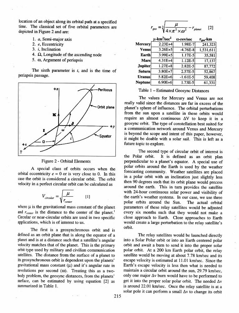
location of an object along its orbital path at a specified time. The classical set of five orbital parameters are depicted in Figure 2 and are:
1. a, Semi-major axis 2. e, Eccentricity 3. i , Inclination 4. n, Longitude of the ascending node 5. w, Argument of periapsis
The sixth parameter is t, and is the time of periapsis passage.
Figure 2 - Orbital Elements
A special class of orbits occurs when the orbital eccentricity e = 0 or is very close to 0. In this case the orbit is considered a circular orbit. The orbit velocity in a perfect circular orbit can be calculated as
V"''""' = ~ Jl I II reenter
where f.t is the gravitational mass constant of the planet and r eenter is the distance to the center of the planet. 1
Circular or near-circular orbits are used in two specific applications, which is of interest to us.
The first is a geosynchronous orbit and is defined as an orbit plane that is along the equator of a planet and is at a distance such that a satellite's angular velocity matches that of the planet. This is the primary orbit type used by military and civilian communication satellites. The distance from the surface of a planet to its geosynchronous orbit is dependent upon the planets' gravitational mass constant (J.t) and it's angular rate in revolutions per second (ro) . Treating this as a twobody problem, the geosync distances, from the planets ' surface, can be estimated by using equation [2] as summarized in Table 1.
215
s Mercury
Venu Earth Mars
Jupiter Saturn Uranus
Neptune
2.23E+4 3.26E+5 3.99E+5 4.31E+4 1.27E+8 3.80E+7 5.82E+6 6.90E+6
1.98E-7 241 ,323 -4.76E-8 1,531,611 1.17E-5 35,581 1.12E-5 17,137 2.82E-5 87,772 2.57E-5 52,867
-1.61E-5 59,408 1.73E-5 61 ,331
Table 1 - Estimated Geosync Distances
The values for Mercury and Venus are not really valid since the distances are far in excess of the planet's sphere of influence. The orbital perturbations from the sun upon a satellite in these orbits would require an almost continuous L\ V to keep it in a geosync orbit. The type of constellation best suited for a communication network around Venus and Mercury is beyond the scope and intent of this paper, however, it might be doable with a solar sail. This is left as a future topic to explore.
The second type of circular orbit of interest is the Polar orbit. It is defined as an orbit plan perpendicular to a planet's equator. A special use of polar orbits around the Earth is used by the weather forecasting community. Weather satellites are placed in a polar orbit with an inclination just slightly less then 90 degrees such that its orbit plane would precess around the earth. This in tum provides the satellite with 24-hour continuous solar power and visibility of the earth's weather systems. In our case, we use three polar orbits around the Sun. The actual orbital parameters of these relay satellites would be adjusted every six months such that they would not make a close approach to Earth. Close approaches to Earth1 would create a large perturbation to the relay satellite's orbit.
The relay satellites would be launched directly into a Solar Polar orbit or into an Earth centered polar orbit and await a bum to send it into the proper solar polar orbit. At a 200 km Earth polar orbit, the relay satellite would be moving at about 7.78 km/sec and its escape velocity is estimated at 11 .01 km/sec. Since the Earth's escape velocity is less then what is needed to maintain a circular orbit around the sun, 29.79 km/sec, only one major L\v bum would have to be performed to get it into the proper solar polar orbit. The needed L\v is around 22.01 krnlsec. Once the relay satellite is at a solar pole it can perform a small L\v to change its orbit

plane to maintain an adequate distance from Earth. In the event that the relay satellite needs to be retrieved, then it could perform a 11v at one of the solar poles and be placed on an intercept course to earth to arrive in six months.
Inter-Planetary Distances
Planetary motions are well understood and have been for several centuries. Table I is an estimate of the range of distances between planets in our solar system. The largest distances between planets are in the upper right area and the smallest in the lower left of the table.
The estimated distances in Table 2 were calculated with two simplifying assumptions. First, distance corrections due to orbit inclination were ignored because they were so small. For planets from Mars to Neptune the errors were in the hundredths of a percent. For Venus it was .175% and for Mercury it was .746%. Secondly, due to the numerical approach used, distances calculated were based upon orbit segment that divided a planets orbit into 3600 segments or 1110 of a degree. This assumption produced distance errors in the thousandths of a percent for all of the planets except Mercury, which had the largest error of ±0.0367%.
Propagation Delays
Using the estimated distances in Table 2, one can estimate the range of propagation delays between planets. A simplified model of propagation delays considers only two types of delay. These are: I) free
space delay (which is distance d times the speed of light c) and 2) planetary delay. The sum of these delays yields an estimate of total delay.
TotDly = Planetldly + Planet2dly + (d x c) [3]
A large contribution to propagation delay is a result of free space delay. The distances in the solar system make real-time interactive sessions impractical in certain situations. Table 3 summarizes the range of propagation delays that could be expected throughout the solar system based on distances in Table 2.
Delays in the relay satellites do exist but are so small and constant that they can be ignored. Relay delay is simply a result of the repeater/router functions. Based upon current switch and router technology these delays range from .2 to 20 milliseconds.
Planetary delays can be treated as a constant and are estimated as the average delay between a geosync satellite network and it's terminal location. This delay includes: I) terminal processing delays, 2) satellite processing delays, if satellites are used in a planetary network, and 3) atmospheric delays or transit delays if data is being directed to an adjacent moon. Clearly, for planets such as Jupiter, its moons would be considered the planet's terminal location and delays would be calCulated accordingly.
Satellite processing delays are very low and can be estimated at 15 ms. Ground terminal delays have typically been much more significant due to multiplexer, switching, encrypting, routing and decoding functions. These ground terminal delays can be as high as 450 ms.
Maximum Inter-Planetary Distances (km) Sun Mercury Venus Earth Mars Jupiter Saturn Uranus Neptune
1.09E+8 2.49E+8 8.16E+8 1.50E+9 3.03E+9 4.
2.95E+8 1.55E+9 3.08E+9
1.61E+9 3.14E+9
1.47E+8 1.65E+9 3.18E+9
2.07E+8 1.71E+9 3.24E+9
3.77E+9
1.30E+9
2.67E+9 2.58E+9
4.42E+9 4.34E+9
Table 2 - Range of Distances throughout the Solar System
216
Maximum one way Inter-Planetary free-space Delay (seconds) Sun Mercury Venus Earth Mars Jupiter Saturn Uranus Neptune
Venus
Earth 491 10,623 15,638 Mars 689 10,947 15,962
2,471 12,837 17,852 4,494 4,261 3,987 20,137 9,126 8,894 8,619 8,295
14,980 14,747 14,473 14,148 12,258
Minimum one way Inter-Planetary free-space Delay (seconds)
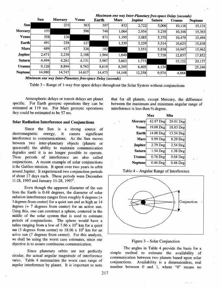
Table 3 - Range of 1-way free space delays throughout the Solar System without conjunctions
Atmospheric delays or transit delays are planet specific. For Earth geosync operations they can be estimated at 119 ms. For Mars geosync operations they could be estimated to be 57 ms.
Solar Radiation Interference and Conjunctions
Since the Sun is a strong source of electromagnetic energy, it causes significant interference to communications. As the Sun moves between two inter-planetary objects (planets or spacecraft) the ability to maintain communication degrades until it is no longer possible to operate. These periods of interference are also called conjunctions. A recent example of solar conjunctions is the Galileo mission. It spent over two years in orbit around Jupiter. It experienced two conjunction periods of about 17 days each. These periods were December 11-28, 1995 and January 11-28, 19972
•
Even though the apparent diameter of the sun from the Earth is 0.48 degrees, the diameter of solar radiation interference ranges from roughly 6 degrees ( + 3 degrees from center) for a quiet sun and as high as 14 degrees ( + 7 degrees from center) for an active sun. Using this, one can construct a sphere, centered in the middle of the solar system that is used to estimate . periods of conjunctions. The sphere would have a radius ranging from a low of 7.86 x 10⁶ km for a quiet sun (3 degrees from center) to 18.06 x 10⁶ km for an active sun (7 degrees from center). For this analysis, we shall be using the worst case estimates, since our objective is to assure continuous communication.
Since planetary orbits are not perfectly circular, the actUal angular magnitude of interference varies. Table 4 summarizes the worst case range of angular interference by planet. It is important to note
217
that for all planets, except Mercury, the difference between the maximum and minimum angular range of interference is less then 1f2 degree.
Mercury
Venus
Earth
Mars
Jupiter
Saturn
Uranus
Neptune
Max Min
42.87 Deg 29.01 Deg
19.08 Deg 18.83 Deg
14.00 Deg 13.54 Deg
9.99 Deg 8.29 Deg
2.79 Deg 2.54 Deg
1.54 Deg 1.38 Deg
0.76 Deg 0.68 Deg
0.46 Deg 0.46 Deg
Table 4 -Angular Range of Interference
Figure 3 - Solar Conjunction
The angles in Table 4 provide the basis for a simple method to estimate the availability of communication between two planets based upon solar conjunctions. Availability is a dimensionless, real number between 0 and 1, where "0" means no

availability and "1" means constant availability. As is observed in Figure 3, the planet nearest to the sun causes the largest conjunction.
Since the solar system is in constant motion with angular velocities that are not changing that fast, the availability can be estimated by subtracting the fraction of the orbit that is in conjunction from 1.
A .1
b .1.
1 ConjuctionAngle [
4] vaz a z zty = - _ _..::. ___ --=:.____
360
In addition, the sun acts a white noise jammer of ground surface terminals when the Sun is aligned with the downlink terminal beam. This alignment happens twice a year around the equinoxes for geosync satellites. During this period, around the equinox, the ground terminal's receiving system is saturated with the sun's radio signal for short periods each day. We will call this Geosync jamming. The period of disruption is also based upon solar activity. Worst case outages for a quiet sun can be as long as 23 minutes and for an active sun it can be as high as 55 minutes. Assuming 10 hours a year of outages due to this type of conjunction yields an availability contribution of 0.998859 defined as A8. An overall availability, A0 ,
can be derived using the model of series systems3 as follows :
[5]
By applying the above relationship to the angles listed in Table 3, we can estimate the availability ranges due to solar conjunctions. The results, A"' are summarized in Table 4.
Planetary Interference (Conjunctions)
Planetary interference is based on planets that travel through the communication path. While this
Mercury Venus Earth Mars
effect is small, it is relevant since our objective is to achieve continuous connections. These planetary conjunctions can be grouped into two sets: l) conjunctions caused by a planet's satellite moons and 2) conjunctions caused by other planets.
Detailed calculations of planetary conjunctions is beyond the intended scope of this concept paper, but they must be considered as part of the analysis in setting up a planet's satellite constellation even though their significance is small. For example, the Earth's viewing availability without an impact from a moon conjunction is .9999979882. Mars viewing availability without an impact from a Phoebes conjunction is .9999996265.
Polar Orbiting Satellite Relay Conjunctions
Since the solar polar orbiting satellite relay is perpendicular to the primary planetary orbit planes, the availability calculations use the ratio of surface area of a sphere instead of the ratio of a circle as done above. This is reasonable since all of the solar polar orbiting satellites are at approximately 1 AU with an inclination of 90 degrees. The spherical surface is thus 2.81 x 10¹⁷
km2. Using the worst case conjunction range of± 7
degrees, this results in 1.05 x 10¹⁵ km2 of surface area that is not visibte. This yields a visibility availability of .99627 for each solar polar orbiting satellite when viewed by Earth.
For Mars to Neptune, the availability is reduced when the solar polar orbiting satellite is in the planet's line of sight with the sun. This is the same type of interference effect as with geosync orbiting satellites during periods of equinox. This is listed in Table 6.
Maximum Solar Conjunction Availability Saturn Uranus Neptune
Uranus ~-~-4-----4----4-----+----4~----
Neptune L-----L---~----J_---~---~L_ ___ J_ ___ __
Minimum Solar Conjunction Availability
Table 5- Range of Solar Conjunction Availability's with Geosync jamming
218

Mars 0.99543
Jupiter 0.99333
Saturn 0.99261
Uranus 0.99223
Neptune 0.99280
Table 6- Outer Planet Relay Availability's
The availability for Venus is lower since it is closer to the sun and estimated at .99314. For Mercury, it is even lower ranging from .96540 to .98407. This is due to Mercury's orbit that has a wide range of angular conjunction as noted in Table 3. Note: in all cases the availability is higher for the relay satellites. This is because of its polar orbit that provides broader view angles, as is evident in the availability numbers.
Using the reliability model of redundant systems, we can estimate the new availabilities. This is defined as :
ACompo.1ite = 1- (1- ABasic )x (1- ARelay) [6]
where Asasic is the existing planet availability, A Relay is the relay satellite availability and Acomposire is the new estimated visibility availability.
Mercury
Venus
Mars
Jupiter
Saturn
Uranus
Neptune
Aaasic Acomposite
0.87992 0.99585
0.94592 0.99963
0.96002 0.99982
0.97115 0.99981
0.99111 0.99993
0.99460 0.99996
0.99676 0.99998
Table 7 - Availability comparison with 1 relay
While the presence of one solar polar orbiting satellite relay significantly improves visibility its availability's is still not 1. Since most of the conjunctions occur within a 20-degree band along the solar systems' orbital plane, the question exists on how to position a constellation of relay satellites such that there is always one satellite above the conjunction band. We propose three satellites, separated by about 120 degrees. As noted in Figure 4, this configuration will always assure that at least one relay satellite is not in a conjunction - thereby providing continuous communications access.
Satellite Reliability - Availability
Even though proper positioning of the solar polar orbiting satellites can achieve a theoretical
219
availability of 1, the fact is that satellites do fail and the impact that these failures have on overall availability needs to be understood. Current experience indicates that the life span of a relay satellite can be assumed to be five years.
. ~ ~. v .... v '-·'
,~ / .,
\ / \/ ', 1/ ' /\ /\, I \ I \ ~d· \ I \
\ a 6~ I ~7 lrt Ill I ~\ z a J.a 2 D :J 0., :J ~ .J. D .
\ / \7 "'\ l \
/ ~ / \ 7 '
~ ,...
/ ...
./ .. . .. ,/ L_ "~ .
Figure4 - Relay Satellite Phase Alignment
The reason for understanding the impact deals with what type of satellite backup plans should be developed. For example, is it cost effective to place hot spares in orbit and activate them when an operational satellite fails, or is better to store the backup satellites on the ground, thereby extending their life and launch them when a failure occurs. This concept paper does not intend to perform this analysis but only to point out that the economic aspects of this infrastructure cannot be considered complete without addressing reliability and sparing issues.
Solar Time Exchange and Synchronization
One key aspect of this satellite relay concept is the critical need for satellite relays to maintain time in a manner that time accuracy is good to about ! 1 millisecond. Maintaining time is critical in the calculations· of which route to take based upon continuously changing propagation delays. Data transmitted throughout the solar system via the satellite relays would need to be time stamped to determine the age of the data being transmitted.
When time is being synchronized among the satellites, a hierarchy needs to exist. We suggest that Earth be established as the Master clock source. The three solar polar orbiting satellites would be slaved to the Earth Master source. Planetary satellites would be slaved to the Solar Polar orbiting satellites. There are various departures that could be used in the event of a problem, but as a normal mode of maintaining time, the described hierarchy works.
Errors are introduced by posttlon and clock drift errors. If the intent is to maintain relay clocks to millisecond accuracy, then one has to know what are

the contributors to errors so as to control them. This paper did not intend to calculate time errors associated with position errors, but we did estimate the worst case velocity error that occurs. We calculated the worst case velocity error to cause an error of ± 2.4 1.1s. This worst case error is the result of a Mercury orbit with a relay satellite processing delay of 15 ms.
While many protocols exist, a simple one suggested for this application is an exchange of time stamped messages between a requesting and a replying relay satellite. The time requestor would send a time request message that contains requestor ID, requestor local time and position. The time replying relay would append its own ID, local time and position. Once the requestor receives the time stamped message, it calculates the send and receive times, correcting for Doppler shifts, position errors, etc. With corrections, the send and receive times should be equal and if not the requestor would split the difference, update its local clock and request another time stamped message.
Communication Perfonnance Assessment
We have presented a satellite constellation, which from an orbital mechanics perspective offers the potential for continuous data connectivity to far reaches of our solar system. We have determined the minimum and maximum distances between the planets and calculated the worst case satellite to planet propagation delays. The purpose of this portion of the analysis is to identify and quantify key communication design parameters and assess system performance.
Since the earth already has a substantiate infrastructure suitable to transfer video, voice and data, we tum our attention to the communications subsystem of the proposed satellites that would orbit the sun. These satellites could communicate with the existing earth infrastructure and would act as satellite-tosatellite relays, also known as satellite cross-links, to
relay signals to their intended receiver located in deep space. The destination could be personnel transports in route to Neptune, for example, or a satellite cross-link in orbit around Neptune. This is depicted in Figure 5. For the purpose of this analysis, the satellite cross-links are assumed to have the same characteristics in both directions.
Design trades for a satellite communication subsystem hinge on the relationship between power, bandwidth and weight constrai~ts. Key factors in the design trade include the planned operating frequency, selection of the antenna type, choice of modulation format, and the required system performance.
Probably the most telling performance parameter to quantify data quality is the bit error rate (BER). For this analysis, we target a delivered BER of at least 1.0E-6. This is assumed to be the minimum acceptable data quality needed to support voice, video and data.
Another key design factor is the selection of frequency. In this paper we follow the lead of the international community, which has allocated bandwidth in the 60 GHz region for satellite-to-satellite communications. Benefits of this frequency choice include smaller antenna size, greater antenna directivity, bandwidth availability, and inherent security against ground interception of satellite-tosatellite transmissions due to greater atmospheric attenuation.4
Phased array and parabolic antenna designs are both viable options to consider for satellite cross-links. It has been shown that for data rates above 10 KBPS, the paraboloid is both lighter and requires less transmit power than the phased array5
• For this reason, we assume a parabolic antenna throughout the analysis.
For several reasons, the modulation format quaternary phase shift keying (QPSK) was selected fQr
~--··----·---.. ...... _
/''•""• G
............. ~/ '--·-·-·--·---·--"""
Worst Case Cross-Link
Figure 5 - Worst Case Satellite Cross-Link
220

this analysis. Constant envelope modulation techniques such as phase sbift keying (PSK) are less susceptible to degradation caused by non-linearities induced by power amplifiers and other devices. The most compelling reason however, is the bandwidth efficiency of 2 bit/s/Hz for QPSK versus 1 bit/s/Hz for binary PSK. Although higher bandwidth efficiency can be obtained with M-ary PSK (M>4), the power requirements for these methods are prohibitive.
The figure of merit that best quantifies the performance of a digital communication system is the BER. The BER is usually plotted against the ratio of bit energy to noise power spectral density, Et,/N0 • The bit energy of a signal, s(t), is simply
where 't is the bit period, No = kT, k is Boltzmann's constant (1.38e-23 J/K) and Tis the noise temperature in Kelvin.
Figure 6 contains the probability of bit errors, Pbe, for uncoded QPSK modulation given b/
P. ~QtE, be N
0
[8]
1 00 _;..2
where Q(k) = ~ f e-2 dlt [9] ...;21! k
For a BER of 1.0E-6 it can be seen that a minimum Et/No of 10.7 dB is required.
With these design decisions made, and the minimum E.,!N0 identified, we continue with the analysis. The relationship of Et!No to receive power and data rate is given by
Eb = P. *-~--No No R,
[10]
where R 1
, the transmission data rate, is 1/'t.
The receive power, Pn is given by Eq. [11]. Assuming a transmitter with power P, and antenna gain of G, (as defined by Eq. [13]) transmits a signal through a vacuum medium to a receiver with antenna gain Gn then the received power is given by
~ = P,G,G, r L s Li
[11]
where Ls is defined in Eq. 12 to be the path loss associated with traveling distance d meters through the
221
vacuum medium at frequency f (Hz) and Li is the sum of implementation losses6
•
Theoretical QPSK Modem Performance
.I -~
~ - - ..1.. - - ..;, - !_ -· -~ -
' ' 1---"-T--...;-1.00E-<l1
11 .. 00EOOE: -- ~ ~; = ~ -: . ~ ~:-- -!~ ~- ~- ~:- ~~-~ I, "'N · ··· r ··· ··· - r ··
~ ! I 1.00E-o4 ... ! .. . " .. ' : I
j ::: . , .: .. : I
:::: .. ·· I ·· ···r I . ,_. ,, ':' ' ·:··.· .. ··· ' ''' I 1.00E-<l9
1.00E·10 .. +-,-!-f'--l--f-+- t-- l- + -+-+-1- - !-;
0 1 2 3 4 5 6 7 8 9 10 11 12 13 14 15
EbiNo (dB)
Figure 6 - Theoretical QPSK Modem Performance
L s = (41fdj Y c )
[12]
For an antenna operating at frequency, f hertz, the antenna gain is given by
4Jt4. f 2 G =T7--c2 [13]
where 11 is the antenna aperture efficiency (11< 1), A is the aperture area in square meters and c is the speed of light in rn/s.7 Typical values of 11 for paraboloids range from 0.5 to 0.6 and 11 is taken to be 0.6 for this analysis. Since atmospheric losses are not of concern, we make the simplifying assumption that the transmit and receive antennas operate at the same frequency and are identical, hence G = G1 = G,. For a circular aperture A= 1tD2/4, the gain given by Eq. 13 becomes
G = 17( 1!Df y c )
[14]
Plugging Equations 12 and 14 into Equation 15 results in the following simplified expression
P, = P,G,G, =:~*(7!17D2/)2 [15] LsLi Li 4dc
where all parameters are as previously defined. The sum of all transmitter and receiver losses Li, which include antenna-pointing losses, tracking losses, waveguide losses, and cross polarization losses are
Antenna Efficiency e =
Antenna Diameter D =
Distanced=
Frequency f =
Speed of light c =
Boltzmann's constant k =
System Temperature Tsys =
Li=
Transmission Data Rate Rt =
Transmitter Power Pt =
Mars
Worst Case
0.6
6
2.49E+11
2.00E+10
3.00E+08
1.38E-23
30
2.51
2.10E+04
20
Mars Neptune Neptune
Best Case Worst Case Best Case
0.6 0.6 0.6
6 8 8
2.49E+11 4.54E+12 4.54E+12
6.00E+10 6.00E+10 1.00E+11
3.00E+08 3.00E+08 3.00E+08
1.38E-23 1.38E-23 1.38E-23
30 30 30
2.51 2.51 2.51
2.10E+04 2.10E+04 2.10E+04
20 20 20
Meters
Meter
Hertz m/s
J/K
Kelvin
BPS
watts
Table 8 - Summary of Physical Design Parameters
Pr =
No=
Pr/No =
Eb/No =
@ l.OE-6 BER = Req. Eb/No
Th reshold Margin
Coding Gain
Desi&r;n Mar&jn
Rc=
Information da ta rate, Rc*Rt =
Mars
Worst Case
-157.84
-213.83
55.99
12.76
10.70
2.06
7.00
9.06
0.48
1.00E+04
Mars
Best Case
-148.30
-213.83
65 .53
22.31
10.70
11.61
7.00
18.61
0.48
1.00E+04
Neptune
Worst Case
-168.52
-213 .83
45 .31
2.09
10.70
-8.61
7.00
-1.61
0.48
1.00E+04
Neptune
Best Case
-164.09
-213.83
49.74
6.52
10.70
-4.18
7.00
2.82
0.48
1.00E+04
DBW
dBW-Hz dB dB
dB dB
dB
dB
bps
bps
Table 9: Link Budget
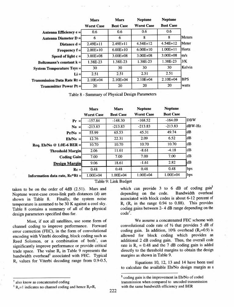
taken to be on the order of 4dB (2.51). Mars and Neptune worst-case cross-link path distances (d) are shown in Table 8. Finally, the system noise temperature is assumed to be 30 K against a cool sky. Table 8 contains a summary of all of the physical design parameters specified thus far.
Most, if not all satellites, use some form of
channel coding to improve performance. Forward error correction (FEC), in the form of convolutional encoding with Viterbi decoding, block coding such as Reed Solomon, or a combination of both t, can significantly improve performance or provide critical trade space. The value Rc in Table 9 represents the bandwidth overhead* associated with FEC. Typical
Rc values for Viterbi decoding range from 0.9-0.5,
t also know as concatenated coding * Rc= I indicates no channel coding and hence Ri=R1
222
which can provide 3 to 6 dB of coding gain§
depending on the code. Bandwidth overhead associated with block codes is about 6-12 percent of Ri (Rc in the range 0.94 to 0.88). This provides coding gains between 2- 4 dB range depending on the code7
•
We assume a concatenated FEC scheme with convolutional code rate of '12 that provides 5 dB of coding gain. In addition, 10% overhead (Rc=0.9) is allowed for block coding which provides an additional 2 dB coding gain. Thus, the overall code rate is Rc = 0.48 and the 7 dB coding gain is added directly to the threshold margins to obtain the design margins as shown in Table 9.
Equations 10, 12, 13 and 14 have been used to calculate the available Eb/No design margin as a
~ coding gain is the improvement in Eb/No of coded transmission when compared to uncoded transmission with the same bandwidth efficiency and BER

function of data rate. Table 9 contains the results of the link budget calculations based on the physical values from Table 8. It was noted that at 20 GHz, the worst case Neptune cross-link design margin was -11.16 dB. To improve performance without increasing weight, we recommend increasing the operating frequency using emergent 100 GHz technologies. Therefore, calculations at 100 GHz have been included. At 100 GHz the receive Eb/No becomes -1.61 dB at l.OE4 bps as shown in Table 9.
Figure 7 shows that the information throughput, Rj, is between 3.0E3 bps and 3.0E5 bps at a BER of 1.0E-6 for a reasonable design margin of 3 dB. A summary of key system parameters is provided in Table 10 as a reference.
50 H·-·rrrmtn--r- rrmm- r·rnnnr-rrnnm·-r··,,,,,,r- -r-r nntrrllnr I 11111111 I 11 111111 I 11111111 I 11111111 I 11111111 I 11111111 I 1 1 11111
40
30
20
10
0
-10
-20
-30 JJUW~JJ UW~JJUW~J JUW~JJUW~JJ_ 1111 I 1111111 I 111 11111 I 1 1111111 I 11 11 11 11 I 111 111 11 I 11111111 I IIIII --.lit ti ll I 11 111111 I 111111 11 I 1 1111111 I 11111111 I 11 111111 I 1 1111111 I I I IIIII
I>"' I'":J <? I>" <I' ~ ,.l ... ~ ... ~ .... ... ~ .... ... ~ .... lnfol'll\llaon Throughput (bps)
Figure 7: Estimated Information Throughput
Mars
Worst Case
Mars
Best Case
Neptune
Worst Case
Neptune
Best Case 13.01 13.01 13.01 13.01 59.77 69.31 71.81 76.24 -2.00 -2.00 -2.00 -2.00 70.78 80.32 82.82 87.25 59.77 69.31 71.81 76.24 -2.00 -2.00 -2.00 -2.00
Pt= Tx Antenna Gain =
Tx Loss=
EIRP=
Rx Antenna Gain =
RxLoss =
Path Loss=
Pr=
-286.39 -295.93 -32l.l5 -325.58
dBW dB dB dBW dB dB dB dBW -155.84 -146.30 -166.52 -162.08
Table 10: Summary of Key Parameters
Enabling Technologies of Interest
Although there are many new technologies with application to space exploration, here are a few of special interest to the authors.
One of the most promising and exciting areas of research in recent years arouse out physics and the study of biological sensory systems. Stochastic Resonance (SR) is a phenomenon witnessed in certain bistate nonlinear dynamic systems in which an increase in input noise combines with a weak periodic input signal to improve the coherence (i.e., SNR) of the output signal. 8
•9
·10 Recently, research has proven that
SR phenomenon extends to weak aperiodic (information bearing) input signals as well. 11 As of late, scientists are studying SR in the context of information theory 12 with results that encourage the application of SR to areas in communications including current wireless technologies (Code Division Multiple Access) and encryption technologies. It is fascinating to note the counter intuitive nature of SR and its stark contrast to the conventional knowledge and treatment
223
of noise in today's communication systems, which are linear by design.
Another ingenious idea called the Inflatable Antenna Experiment is being conducted by NASA and will fly aboard STS-77 this May. 13 With significant weight reduction, compact transport form and large antenna size, inflatable antennas could significantly improve spacecraft design and performance.
Currently, satellite communications are based on the electromagnetic radiation of signals in the RF region. Future communications will no doubt utilize laser beams to transfer information nearly error-free in the gigabit per second range. The advantage of laser cross-links is its resistance to interference in the microwave region. Disadvantages include the need for more stringent pointing accuracy and increased sensitivity to intense receive power levels that could destroy unprotected optical sensors.
The current explosion in network technology offers additiona~ areas of interest. A TM switching and routing features is very applicable to a satellite based

relay system. The methods used in the wireless communication industry to transfer calls between cells are also applicable to the proposed satellite relay concept.
System Design Trade Space
Seeing that many design trades need to be performed before this concept could be realized, we have grouped the trades into three areas consisting of communication architecture, physical constraints, and of course life cycle costs/business case.
Additional studies and trades need to be done to address the overall communication system architecture. Topics such as bandwidth demand, switching and routing strategy, use of packet technologies, signaling methods, switch control , bandwidth management, and error control need to be assessed to optimize system functionality and performance. One key consideration is to strive for a scaleable system design that allows for growth without system redesign.
Physical design constraints create contention for spacecraft power, weight and performance. We have focused · on the performance between interplanetary relay satellites; however, design challenges for cross-links between the three solar polar relays have not been addressed. In addition, refinement to calculations on the size of the solar sphere of interference is also needed. This paper treated the solar sphere of interference as a constant, but in fact the sphere changes over time due to solar activity. Further study on weather to treat the solar interference sphere as static or dynamic needs to be performed.
Finally, design life issues have a strong impact on overall life cycle costs. The business case, or cost effectiveness of this communication infrastructure is very significant. Design life is driven by the sparing concept, be it a hot spare on orbit or cold spare on ground. In addition, provisions for technology infusion, launch costs, replenishment costs and ground station costs all need to be considered to establish and accurate life cycle cost estimate. Like it or not, reality necessitates the development of a business model.
Conclusion
Future exploration and exploitation of our solar system requires a solar system information highway. A concept was presented for an infrastructure that provides continuous communication between various inter-planetary objects (planets or spacecraft). Such a system could be designed and deployed using today' s technologies, but the economic
business case still needs to be developed to reveal which technologies (current or future) provide the best overall utility and cost performance. The backbone of the concept is the deployment of three polar orbiting satellites around the Sun that are cross-linked to minimize planetary and solar radiation interference.
Since Mars is our nearest neighbor, it is a likely candidate for early exploration. The solar system information highway described within could initially be deployed to support Mars exploration. Mars exploration would require three geosynchronous satellites and optional polar or Molyain satellites to provide Martin polar cap coverage could be deployed. When the time comes to go beyond Mars, the concept is scalable to support solar system wide communication needs into the foreseeable future.
References
1 Bate, Mueller and White, Fundamentals of Astrodynamics, Dover Publications, 1971 , 0-486-60061-0 2 http://www.jps.nasa.gov/galileo/faghga.html 3 Military Handbook-338, Volume 1, 15 October 1984 4 W. C. Cummings et al., "Fundamental Performance Characteristics That Influence EHF MILSATCOM Systems," IEEE Trans. Com., vol. COM 27, no.l 0, Oct 79 5 R. C. Johnson, Antenna Engineering Handbook, Third Edition, McGraw-Hill, New York, 1993 6 B. Sklar, Digital Communications Fundamentals and Applications, Prentice Hall , New Jersey, 1988 7 T. T. Ha, Digital Satellite Communications, Second Edition, McGraw-Hill, New York, 1990 8 R. Benzi, A. Sutera and A. Vulpiani "The mechanism of Stochastic Resonance," J. Phys. A: Math. Gen.14L453 (1981) 9 Frank Moss et al., "Stochastic Resonance Tutorial And Update," Int. J. Bifurcation and Chaos, Vol. 4, No.6 (1994) 1383-1397 10 F. Moss, K Wiesnfeld, " The Benefits Of Background Noise," Scientific America, Aug. 1995 11 J.J. Collins, C.C. Chow and T.T. Imhoff "Aperiodic , stochastic resonance in excitable systems," Phys. Rev. E52 R3321 (1995) 12 Xavier Godivier and Francois Chapeau-Blondeau," Stochastic Resonance In The Information Capacity Of A Nonlinear Dynamic System, Int. J. Bifurcation and Chaos, Vol. 8, No. 3 (1998) 581-589 13 Aerospace Technology Innovation, Volume 4, Number 2 May/June 1996
224