concept validation study for fuselage wake- … · hoegskola, mtu aero engines, politechnika...
TRANSCRIPT
1
Abstract
The present paper provides an overview together with intermediate results of the work-in-progress research performed in the EC-funded Horizon 2020 collaborative project CENTRELINE (“ConcEpt validatioN sTudy foR fusElage wake-filLIng propulsioN integration”), aiming at demonstrating the proof of concept for a ground-breaking approach to synergistic propulsion-airframe integration, the so-called Propulsive Fuselage Concept (PFC). The concept features a turbo-electrically driven propulsive device integrated in the very aft-section of the fuselage, dedicated to the purpose of fuselage wake-filling. Currently at TRL 1-2, CENTRELINE’s target is to mature the technological key features of the PFC to TRL 3-4. The core of the targeted proof-of-concept is formed by two experimental test campaigns supported by high-fidelity 3D numerical simulation and integrated multidisciplinary design optimisation techniques for aerodynamics, aero-structures as well as the energy and propulsion system.
1 Introduction
Challenged by aviation’s long-term sustainability goals stipulated by the European Commission [1] and the Advisory Council for Aviation Research and innovation in Europe (ACARE) [2], the exploration of breakthrough technological advancements is crucial. Great potential for significant contributions to achieving these goal settings is expected from
novel propulsion systems and their more synergistic integration with the airframe. In order to elude the weight and drag penalties of high propulsive efficiencies that occur under conventional systems integration paradigms, a particularly promising approach is linked to the idea of distributing the propulsive thrust along main components of the airframe. The benefits expected from such distributed propulsion are versatile, including enhanced structural load alleviation, improved propulsor noise shielding, increased high-lift capability through vectored thrust and/or super-circulation, improved reliability due to intrinsic redundancy, as well as the elimination of aircraft control surfaces and/or enhanced control authority. The strongest impact in terms of overall vehicular propulsive efficiency improvements through propulsive thrust distribution in large commercial aircraft application may be realised through the localised ingestion and re-energisation of the viscosity induced low momentum wake flow of a wetted body via Boundary Layer Ingestion (BLI), also known as wake-filling propulsion integration.
1.1. Fuselage wake-filling propulsion integration
Instead of a locally separated compensation of the viscous momentum deficit by excess momentum in the propulsive jet of podded power plants, wake-filling propulsion integration aims at eliminating the effects of viscous drag in the aircraft's wake flow. This immediately allows to
CONCEPT VALIDATION STUDY FOR FUSELAGE WAKE-FILLING PROPULSION INTEGRATION
Arne Seitz1, Fabian Peter1, Julian Bijewitz1, Anaïs Habermann1, Zdobyslaw Goraj2,
Mariusz Kowalski2, Alejandro Castillo Pardo3, Cesare Hall3, Frank Meller4, Rasmus Merkler5, Olivier Petit6, Sebastian Samuelsson6, Biagio Della Corte7, Martjin van Sluis7,
Guido Wortmann8 and Martin Dietz9 1Bauhaus Luftfahrt e.V., 2Warsaw University of Technology, 3University of Cambridge,
4Airbus Innovations, 5MTU Aero Engines, 6Chalmers University of Technology, 7Technical University of Delft, 8Siemens AG, 9ARTTIC
Keywords: Propulsive Fuselage, Wake-Filling, Boundary Layer Ingestion, Propulsion Integration

SEITZ ET AL.
2
reduce propulsive jet velocities, and thereby the kinetic energy loss in the vehicular wake. For large commercial aircraft in cruise, the share of viscous and form drag typically ranges between 60–70% of the total drag. Approximately half of this share may be attributed to the fuselage body, making it the most interesting airframe component to be utilised for the purpose of wake-filling propulsion integration. The principle of wake-filling through BLI has been subject to theoretical treatise over several decades (e.g. Smith et al. (1947) [3], Goldschmied (1954) [4], Smith (1993) [5] and Drela (2009) [6]), and various concepts on how to utilise the potential benefits have been proposed. For fuselage wake-filling propulsion a number of low-TRL paper studies exist, including NASA's “FuseFan” concept [7], the Bauhaus Luftfahrt “Claire Liner” [8], the MIT “D8” concept [9], the EADS/AGI “VoltAir” [10], the Boeing “SUGAR Freeze” [11] and the NASA “STARC-ABL” [12]. A first patent with explicit reference to fuselage wake-filling propulsion integration was filed in 1941 [13]. Initial experimental studies related to fuselage BLI and wake-filling were conducted for the boundary layer controlled airship body concept proposed by F.R. Goldschmied in 1957 [14]. Very recently, low-speed wind tunnel experiments were performed on a generic streamline body by ONERA [15]. First experiments have also been performed at MIT for the D8 configuration [16]. Examples of existing aircraft utilising aft-fuselage propulsion integration, however not explicitly designed to maximise wake-filling, include the Douglas XB-42 (1944), the RFB Fantrainer (1978), the LearAvia LearFan 2100 (1981), and, the Grob GF 200 (1991). A most straightforward way to realise fuselage wake-filling is by full annular BLI through a single propulsor that concentrically encircles the very aft-section of the fuselage. This so-called "Propulsive Fuselage Concept" (PFC) (cf. Fig. 1), offers the full fuselage wake-filling potential together with less complex propulsor inflow-distortion patterns, i.e. only radial in ideal cruise condition, compared to a series of small
propulsors circumferentially arranged around the fuselage aft-section.
Fig 1. Artist view rendering of Propulsive Fuselage Concept
The first multidisciplinary design study of a PFC systems layout for large transport category aircraft was performed as part of the recently completed, EC-funded FP7 DisPURSAL project. Here, the PFC technology was conceptualised and assessed under realistic systems design and benchmarking rules for a new aircraft product family in 2035+. Applied to the medium-to-long range, wide-body market segment, a nominal 9% fuel burn reduction (engineering target within a best-nominal-worst interval) on a 4800nm design stage length was predicted relative to an equally advanced twin-engine reference aircraft [17].
1.2. The CENTRELINE Project
As part of its Horizon 2020 Framework Programme, the European Union currently funds a project dedicated to performing the proof-of-concept and initial experimental validation of the promising Propulsive Fuselage Concept – the "ConcEpt validatioN sTudy foR fusElage wake-filLIng propulsioN integration", in short "CENTRELINE" (Grant Agreement No. 723242). Coordinated by Bauhaus Luftfahrt, the consortium of this 3-year project is formed by a strong partnership between industry, research and academia, involving partners from Airbus Defence and Space, Chalmers Tekniska Hoegskola, MTU Aero Engines, Politechnika Warszawska, Siemens, Delft University of Technology, the University of Cambridge and ARTTIC. The Consortium is accompanied by a Technical Advisory Board (TAB) of senior experts from relevant industrial stakeholders of the CENTRELINE technology and reputable

3
CONCEPT VALIDATION STUDYFOR FUSELAGE WAKE-FILLING PROPULSION INTEGRATION
research organisations including the German Aerospace Center DLR and ONERA, the French Research Lab. The CENTRELINE project investigates a twin-engine, turbo-electric PFC systems layout with the aft-fuselage BLI propulsor being powered through generator offtakes from advanced geared turbofan (GTF) power plants podded under the wing (cf. Fig. 2 below). In this arrangement, the aft-fuselage propulsor is solely dedicated to the wake-filling purpose while all residual thrust required for the aircraft to operate is delivered from the wing-mounted GTF engines.
Fig. 2. Evolution of the CENTRELINE technology
concept for fuselage wake-filling propulsion integration (bottom) from the concept formulated during the EC FP7
L-0 project DisPURSAL [18] (top) In comparison to the mechanical drive train concept focused on in the previous DisPURSAL project (cf. [18]), the electric drive approach greatly simplifies the aero-structural integration of the aft-fuselage propulsor. It facilitates the BLI propulsive device to be installed at the very aft-end of the fuselage body, thereby maximising the wake-filling effect attainable from BLI while
minimising losses due to shear flow on the fuselage aft cone. Due to the electric motor drive of the fuselage propulsor, internal flow path losses associated with the S-duct intake and in-flow distortion of the core engine are avoided. Aft-fuselage internal thermal shielding requirements are relieved, as well as internal and external noise and vibrations are reduced. Reduced rotor burst criticality enhances technical safety and reliability. The shortfall of the third gas turbine engine - required for a mechanical fuselage fan drive - reduces overall system maintenance costs. The CENTRELINE project aims at maximising the benefits of aft-fuselage wake-filling under realistic systems design and operating conditions. CENTRELINE will perform the proof of concept and initial experimental validation for the PFC aircraft technology. Targeting a potential technology Entry-into-Service (EIS) of the PFC technology in the year 2035, the high-level objectives of CENTRELINE are as follows:
1) Technology Readiness Level (TRL) 3-4 for the Propulsive Fuselage Concept at the end of the project.
2) 11% CO2 reduction against an advanced conventional reference aircraft equipped with aerodynamic, structural, power plant and systems technologies suitable for a potential EIS year 2035 (the “R2035”).
3) 11% reduction of NOx emissions against the R2035.
Building upon the PFC Technology Roadmap defined in DisPURSAL [19], a more detailed technology roadmap will be developed in CENTRELINE, indicating how to achieve TRL 6 in 2030.
2. Propulsive Fuselage – Proof-of-Concept Methodology
Pursuing the Propulsive Fuselage Concept proof, the CENTRELINE project addresses the main challenges for propulsive fuselage aircraft design (cf. [19]): the obtainment of a thorough understanding of
the aerodynamic effects of fuselage wake-filling propulsion integration;

SEITZ ET AL.
4
a synergistic aerostructural design integration of the BLI propulsor;
the layout and design of the fuselage fan turbo-electric drive train; and,
the multi-disciplinary systems design integration and optimisation at aircraft level.
These challenges are tackled through a set of problem-tailored methods including high end & high fidelity simulation techniques
for the overall aircraft and the fuselage fan aerodynamics, key structural elements as well as the components of the turbo electric drive train;
low speed wind tunnel and BLI fan rig testing; multi-disciplinary aircraft pre-design
integration and optimization techniques; and, a rigorous concept assessment and
benchmarking approach.
2.1. Aero-numerical Simulation
The aerodynamic design analysis work is performed using different levels of problem-tailored numerical simulation methods. For purposes of aerodynamic design space exploration together with basic fuselage and aft-tip nacelle aero-shaping optimisation, a combination of viscous/inviscid Euler coupling and axi-symmetric RANS codes, namely MTFLOW (Multielement Through-FLOW) [20] and ANSYS Fluent® software, is employed. Here, MTFLOW is used for rapid iterations during initial aero-shape refinement, while key aerodynamic design characteristics and performance parameters are derived from the Fluent® simulations. The results of the design space exploratory work are coupled with the overall aircraft design and sizing based on fast-responding semi-empirical methods, developed in-house at Bauhaus Luftfahrt. The more detailed aero-numerical assessment of the overall PFC configuration at on- and off-design conditions is based on comprehensive 3D Reynolds-averaged Navier–Stokes (RANS) simulations (cf. [21, 22]). For turbulence modelling the best suitable approach is identified from a variety of eligible models including the k-epsilon, k-ω realizable, k-ω SST and Spalart-Allmaras methods. New variations to the turbulence models that take into account the
transition being used to evaluate their efficiency in modelling flows where the boundary layer is subjected to a pressure gradient. Based on the 3D meshing various y+ values are being considered in order to gauge the boundary layer behaviour. Also, an unsteady RANS computational approach is considered in order to identify any large-scale vortices in the system, especially the non-uniform inflow developed at high angle of attack conditions. During the overall configuration numerical investigation, the fuselage propulsor is represented through actuator disc theory. The Computational Fluid Dynamics (CFD) modelling setup is validated through stereoscopic Particle Image Velocimetry (PIV) and pressure measurements obtained from the overall configuration wind tunnel test campaign. For the detailed aerodynamic design and performance analysis of the BLI fuselage propulsor, advanced high-fidelity 3D numerical simulations are performed. CENTRELINE deploys the GPU-accelerated CFD code Turbostream [23]. Turbostream, is a 3D, unsteady, RANS solver, which is used in the high-performance computing cluster Wilkes at the University of Cambridge to run full-annulus unsteady CFD simulations of the complete fan system coupled with the non-uniform inlet flow field from the airframe.
2.2. Power Plant System Design and Performance Synthesis
The PFC main power plants are sized and operationally optimised for the additional electric generator off-takes serving the fuselage fan drive. For the preliminary definition of these specialised turbo engines as well as the advanced year 2035 GTF-type reference power plants, the Bauhaus Luftfahrt in-house developed Aircraft Propulsion System Simulation (APSS) framework (cf. [24-27]) was used. The detailed design and performance synthesis for the PFC power plants is performed using GESTPAN, the Chalmers in-house developed solver and simulation tool. Similar to APSS, GESTPAN offers comprehensive simulation capability for advanced engine architectures and allows predictions for engines subject to

5
CONCEPT VALIDATION STUDYFOR FUSELAGE WAKE-FILLING PROPULSION INTEGRATION
extensive power off-take [28]. The tool has robust numerics for off-design [28], allows advanced power plant simulation [29]. Power plant conceptual design, in particular the prediction of weight and component dimensions is performed using a dedicated software called WEICO, developed primarily in the FP6 projects VITAL and NEWAC [30, 31].
2.3. Electric Machinery Design and Simulation
For the turbo-electric drive train, electro-magnetic and mechanical simulations of the electric fuselage fan drive train together with thermal simulations of the associated motor cooling system, are performed by Siemens,. Therefore, Siemens utilizes in-house high-end finite element methods for mechanical, magnetic and thermodynamic computation. The predefined model structure in this setup allows for seamless exchange of models between multiple tools that assess different disciplines. In that way, a “digital twin” model is created that is able to predict the impact of modifications from a mechanical, magnetic and thermal point of view without the need of translating the modified model for each tool.
2.4. Structural Analysis
For the investigation of aero-structural design and integration aspects, state-of-the-art commercial Finite Element Analysis (FEA) numerical methods, ANSYS Fluent® and ABACUS®, are used as evaluation basis for design refinement, eventually targeting component weight estimation. The structural analysis is performed for the most critical load cases defined by CS-25 certification rules. Stress analyses consider internal forces as well as external forces and moments acting on considered structural components (e.g. wing, fuselage and fuselage fan nacelle). This captures surface pressure forces to the aerodynamic loading, propulsion point loads, as well as inertial and gyroscopic load effects. The FEA stress analysis is capable of incorporating non-isotropic material properties as well as heat transfer implications of fuselage fan drive system on
composite structures, i. e. Carbon Fiber Reinforced Polymers (CFRP).
2.5. Overall Configuration Aero-Validation Testing
The core of CENTRELINE’s proof-of-concept for fuselage wake-filling propulsion integration is constituted by two experimental test campaigns aiming at obtaining a fundamental understanding of governing flow physics of both, the overall aircraft configuration and the fuselage BLI propulsor. For the overall configuration aero-validation testing, a wind tunnel model is being developed to be tested tested in the Open Jet Facility (OJF) as well as in the Low Turbulence Wind Tunnel at Delft University of Technology. The wind tunnel model design is based on the initial PFC design specified in the early phase of the CENTRELINE project. The PFC design is scaled down to model dimensions based on an equivalent power coefficient for the full scale aircraft and the wind tunnel model, a Reynolds number and Mach number range that is acceptable for extrapolation to full scale, as well as the measurement ranges of available testing equipment (external balance, rotating shaft balance, pitot probes, PIV). The configuration of the model is modular in order to increase design flexibility during wind tunnel test campaign as illustrated in Fig. 3.
Fig. 3. Configuration of the modular wind tunnel model
The modular model allows the experimental investigation of multiple fuselage aft-sections including the conventional reference geometry for benchmarking purposes as well as different

SEITZ ET AL.
6
PFC designs. The model accommodates a high power pneumatic drive (air motor) and a propulsor that is fixed to a rotating shaft balance. The rotating shaft balance allows the determination of the separate propeller in-plane and out-of-plane forces and moments, which is essential for an accurate thrust/drag bookkeeping. The empennage is modular to allow tail-on and tail off simulations and to quantify the effects of the propulsive fuselage on the static stability characteristics. The wings of the model are stubbed in order to increase the feasible Reynolds numbers during testing, as well as removable to allow quantification of the wing wake-flow effects on fuselage propulsor inflow conditions and overall configuration aerodynamic performance. During the test campaign scheduled to begin Q4 2018, the thrust vector, torque and in-plane forces of the propulsor will be measured separately from the overall forces and moments acting on the fuselage/fan combination using the rotating shaft balance. The PIV measurements will be complemented by surface pressure probes and hot-wire measurements. In order to emulate a realistic relative scale of the fuselage boundary layer, use will be made of boundary layer control in the form of added transition devices where needed, or additional fuselage sections to increase the length and the boundary layer thickness. The wind tunnel results will be post-processed and interpreted by experts to gain a fundamental understanding of the aerodynamic phenomena associated with the overall propulsive fuselage concept. The performance potential of the configuration will be quantified based on the test results. Due to limitations in the Reynolds and Mach number, the wind tunnel test data obtained cannot directly be applied in the analysis of full-scale aircraft behaviour. For this reason, the data set will be analysed in detail to arrive at predictions for full-scale. Existing correction techniques will be applied based on a combination of empirical and computational tools. The flow conditions measured near the fuselage propulsive device will serve as input for detailed simulation and testing of the BLI fan.
2.6. Fuselage Fan Aero-Validation Rig Testing
In order to verify the BLI fan aerodynamics of the PFC, CENTRELINE uses the low-speed BLI Fan Rig facility in the Whittle Laboratory at the University of Cambridge. A basic illustration of the rig is given in Fig. 4.
Fig. 4. Meridional view of the BLI fan rig rig [32]
The advantages of this facility are that the fan can be run with any pattern and intensity of inlet stagnation pressure distortion representative of the flow field from the aircraft airframe entering the fan inlet. Full-annulus area traverses with a 5-hole pressure probe are possible at 5 traverse planes giving complete information on the 3D steady velocity and pressure fields (up to 20,000 measurement points per traverse). Unsteady pressure measurements with up to 18 probes measuring simultaneously are also available for examining the rotor unsteady aerodynamic behaviour. The fan stator and inlet distortion gauze are manufactured from 3D printing facilities within the laboratory and can be changed. The rotor is machined from aluminium on a 5-axis machine, also available in the Whittle Laboratory. The existing low speed BLI fan rig at the Whittle Laboratory, presented in Fig. 4, is currently being modified to match the CENTRELINE configuration. This includes the design and manufacturing of new hub and casing geometry as well as machining of a new set of aluminium rotor blades and 3D printing the stator vanes. The ingested velocity profile from the CENTRELINE airframe will be prescribed using 3D-printed variable porosity distortion gauzes, as detailed in [32]. A baseline fan rotor and stator designed for uniform clean flow will be initially tested. This will then be modified based on the inlet flow-field for the CENTRELINE aircraft design
1 2 3 4 5
Five-hole probe area traverse planes
Distortion gauze
Rotor Stator Throttled exhaust to atmosphere
Flow straightener

7
CONCEPT VALIDATION STUDYFOR FUSELAGE WAKE-FILLING PROPULSION INTEGRATION
operating at cruise. Despite full scale Mach numbers will not be matched on this low-speed rig, the stage hub-to-tip radius ratio and velocity triangles will be representative. Each test in CENTRELINE will include steady area traverses at stations 1-5 in Fig. 4 above. These measurements are time consuming, but accurate to <1% for pressure and velocity. Angle measurements are accurate to <1 degree within the bounds of the calibration map. The rig probes are complemented by rig operating point measurements including rotational speed, ambient conditions, mass flow and inlet duct pressures. The test results will be processed similarly to the approach presented in Reference [32], to confirm the correct inflow has been reproduced, to compare the flow redistribution with the design intent and CFD results, to examine the aerodynamic performance of the fan rotor in distortion and the aerodynamic losses in the fan stator. The key performance measures will be rotor and stage efficiency for clean inflow and the distorted conditions tested. Stability margin will also be determined.
2.7. Integrated Aircraft Sizing Methodology
In order to provide robust design and performance guidelines and to facilitate a quick ramp-up of the detailed numerical and experimental activities in the project, a BHL in-house developed aircraft conceptual design framework [33] was employed. Over the course of the previous DisPURSAL project this methodological setup was extended to allow for the appropriate incorporation of the physical effects associated with the integration of the boundary layer ingesting aft fuselage-installed power plant [18, 34, 35]. After the initial phase of the project a transition to a more sophisticated synthesis framework was successfully conducted using the Common Parametric Aircraft Configuration Schema (CPACS) [36] as the standard for aircraft design data exchange. Over the course of the project, the multi-disciplinary PFC aircraft design and simulation framework is now continuously being extended and refined based on the results and findings obtained from CENTRELINE’s detailed design and analysis tasks.
2.8. PFC Multidisciplinary Evaluation and Benchmarking
In order to critically evaluate the top-level properties of the integrated PFC aircraft design, a multi-disciplinary concept assessment will be performed in the final phase of the project. The assessment will include concept benchmarking with regards to SRIA environmental targets including CO2, NOx and noise, as well as aircraft operating economics by means of Cash Operating Costs (COC), both against the technological competitor aircraft, i.e. advanced conventional R2035, as well as the SRIA reference representing the year 2000 state-of-art. Noise will be assessed using a source based method establishing the overall noise emission estimates against certification procedures [37, 38]. NOx emissions will be derived from the fuel burn saving potential of the PFC as well as project common assumptions on year 2035 combustor technology. Therefore, the employed engine performance and conceptual design codes, GESTPAN and WEICO, are closely integrated with the noise and NOx assessment methodology. The analysis of COC will be performed using a model based on the method published by the Association of European Airlines (AEA) [39] that was refined and customised [40-42]. For the evaluation of fleet introduction scenarios and the estimation of long-term, fleet-level fuel burn impact of the CENTRELINE technology the methods of [43, 44] will be considered.
3. CENTRELINE Technology Application Case
In order to facilitate critical assessment and benchmarking of the PFC technology in CENTRELINE, a realistic application scenario including advanced reference aircraft and propulsion systems for an aspired EIS year 2035 is defined.
3.1. Technology Benchmarking Approach
The establishment of a reference aircraft for an EIS 2035 (R2035) serves the purpose of enabling a fair and sound comparison basis for the

SEITZ ET AL.
8
integration and later assessment of the PFC technology. Additionally, it is important to compare to a year 2000 platform (R2000) in order to judge the relation to the goals defined by the European Strategic Research and Innovation Agenda (SRIA) [2]. The aircraft design synthesis originates from a suitable R2000 design. The incorporation of realistically advanced technologies for an evolved conventional aircraft for the year 2035 yields the R2035 which, in turn, serves as the basis for the introduction of the PFC design. PFC technology evaluation is then performed through comparison of the PFC and R2035 aircraft designs, as well as a SRIA environmental benchmarking exercise against the R2000 aircraft as visualized in Fig. 5.
Fig. 5. PFC technology benchmarking approach
3.2. Aircraft Top-Level Requirements
To maximize the positive impact of the CENTRELINE PFC technology at aircraft fleet level, existing forecasts of market and route development were analyzed in order to identify a most influential aircraft market segment with regards to reductions in fuel consumption. Similar to preceding analyses performed in the DisPURSAL project, the medium to long-range wide-body aircraft segment was determined to be particularly impactful. The correspondingly derived set of Top Level Aircraft Requirements (TLARs) is shown in Tab. 1.
Tab. 1. Top Level Requirements and key properties for
the CENTRELINE R2035 reference aircraft
Basic aircraft top level requirements
Technology freeze / Entry-into-Service
2030 / 2035
Design range 6500 nm
Design payload 340 PAX in 2-class arrangement
Airport compatibility limits (ICAO Annex 14)
Code E (52 m < x < 65 m)
Take-off Field Length (MTOW, SL, ISA)
≤ 2900 m
Second segment climb 340 PAX, DEN, ISA+30°C
Landing Field Length (MLW, ISA)
≤ 2400 m
Approach speed (MLW, SL, ISA)
≤ 145 KCAS
ETOPS Capability 240 mins
Design Service Goal 50000 Cycles
3.3. Year 2000 and 2035 Reference Aircraft Definitions
Given its reasonable similarity with the CENTRELINE TLARs, the Airbus A330-300 aircraft featuring Rolls Royce Trent 700 Series power plants was selected as a basis for the R2000 aircraft model. The aircraft model was validated against payload-range data given in the Aircraft Characteristics – Airport and Maintenance Planning document [45] of the A330. In order to accommodate the required number of passengers, an appropriate stretch version of the A330-300 fuselage was defined for the R2000 aircraft. Therefore, additional weights emanating from necessary structural reinforcements of main airframe components were considered, as well as the increased thrust requirements and aerodynamic performance implications due to the increased aircraft gross weight rating. In order to develop the R2035 from the R2000 aircraft, a comprehensive technology scenario was devised, including advanced multi-disciplinary technological developments considered realistic for aircraft product integration by 2035. Examples of the incorporated technologies are listed below:
SRIA Baseline Aircraft (R2000)
CENTRELINE Reference Aircraft
(R2035)
CENTRELINE Propulsive FuselageAircraftDesign (PFC)
AdvancedConventionalTechnologies
Propulsive Fuselage
Technology
PFC Technology Evaluation
PFC SRIA Benchmarking

9
CONCEPT VALIDATION STUDYFOR FUSELAGE WAKE-FILLING PROPULSION INTEGRATION
Aerodynamics: Riblets covering 70% of fuselage, wing, empennage and nacelle wetted area; advanced composite design enabling maneuver and gust load alleviation and active flutter suppression. Structures: Fuselage geodesic design based advanced composite materials and bonding; wing including 90% advanced composite materials and bonding technologies, additive manufacturing and adaptive dropped hinge flaps; empennage including advanced composite materials and bonding technologies. Systems: All-electric subsystems architecture; fly-by-light control system; furnishings including advanced lightweight material and additive manufacturing. The aircraft level design and performance impact of these technologies was incorporated in the aircraft sizing process through parametric delta assessments in the multi-disciplinary models. The sizing of the R2035 aircraft components considers a product family design including stretch and shrink versions of the baseline aircraft by +/– 15% payload capacity. Basic properties of the R2035 baseline aircraft are given in Tab. 2.
Tab. 2. Key properties of R2035 reference aircraft
R2035 Property Value
Wing span 65 m
Operating Empty Weight 120.2 t
Maximum Take-off Weight 222.9 t
Maximum Wing Loading 644 kg/m²
Design block fuel vs. year 2000 baseline (R2000)
–27%
Compared to the R2000, the R2035 features a larger cabin cross section with a 9-abreast (2-5-2) economy seating arrangement. The maximum wing loading for the R2035 baseline family member is reduced relative to the R2000, in order to offer sufficient margin for stretch potential within the R2035 aircraft family design. The R2035 aircraft is equipped with Geared Turbofans featuring Ultra-High Bypass Ratio (UHBR) > 16, sized to serve the aircraft family design. Power plant thermodynamic cycle parameters and component design properties were selected appropriately to reflect advanced
aerodynamics, materials and manufacturing technologies for an EIS 2035.
4. Initial PFC Aircraft Design
In order to set a consistent basis for the more detailed design and analysis activities, in CENTRELINE, an initial PFC aircraft design was specified through qualitative configurational down-selection and a subsequent preliminary multidisciplinary design loop for the selected PFC aircraft layout.
4.1. Down-selection of PFC Aircraft Layout
In order to identify a most suitable aircraft layout for the PFC proof-of-concept from a number of candidate options, combined sets of decisive quantitative metrics and multi-disciplinary qualitative rating criteria was deployed in a well-structured down-selection process. The considered down-selection candidates were compiled from input of the project consortium. The captured design space included alternative approaches to the aero-structural integration of the aft-fuselage BLI propulsive device as well as different empennage integration options. Key element of the down-selection process was a concept rating workshop involving all project partners as well as the CENTRELINE TAB members. During the workshop, the PFC aircraft configurational candidates were assessed against the turbo-electrically retrofitted PFC design from the previous DisPURSAL project. A total of 35 evaluation criteria grouped in the five main categories, aircraft aerodynamic design, PFC system design integration, weights, noise and aircraft operability & certifiability were taken into account. All concept ratings were discussed comprehensively by the workshop participants and the rating decisions were taken consensually, thereby, ensuring maximum transparency in conceptual decision making. In result, a PFC aircraft configuration comprising T-Tail arrangement with the ducted BLI fan integrated behind the vertical fin was selected as a most suitable basis for the further detailed studies in CENTRELINE.

SEITZ ET AL.
10
4.2. Design Space Exploration and Aircraft Pre-Sizing
In order to gauge the quality of alternative PFC designs during the phase of initial design space exploration the Power Saving Coefficient (PSC) proposed by Smith [5] was employed:
(1)
where PRef refers to the power required to operate the aircraft in the conventional, non-wake-filling case, and, PPFC represents the wake-filling PFC power requirements. The powers compared by the PSC metric in both cases refer to the total Low Pressure Turbine (LPT) power output required in cruise. For the initial PFC evaluation, a simple component based thrust / drag book-keeping scheme as presented by Bijewitz et al. [34] was employed in order to match the results from preliminary CFD simulations on the initial CENTRELINE PFC 2D aero-shaping. Therefore, the drag data for the fuselage + fuselage fan nacelle (in the following referred to the "bare PFC") and the isolated fuselage, as well as the fuselage fan (FF) disc power absorption in the PFC case were extracted from the CFD results. Subtracting the total drag of the bare PFC body from the fuselage fan axial disc force yields the bare PFC net axial force. The net thrust required from the main power plants is reduced by the change in axial force between the R2035 reference fuselage drag and net axial force acting on the bare PFC body. Incorporation of the Fuselage Fan (FF) aerodynamic efficiency and the Turbo-Electric Power Train (TEPT) efficiency, i.e. the product of generator, FF drive motor and Power Management And Distribution (PMAD) system efficiencies, yields the main power plant LPT power offtake required to drive the PFC fuselage fan. In order to allow for parametric design studies, a simple flow profile scaling method was used for fuselage flow field and drag estimation. The method is based on the assumption that a large majority of the fuselage drag is manifested in the fuselage wake-flow momentum deficit and that the cumulative fuselage drag is mainly proportional to upstream wetted surface area. Calibrated to the results of the initial CFD results,
the method allowed for a quick estimation of fuselage drag characteristics as well as fuselage fan inflow conditions including local boundary layer and momentum thickness, and, mass flow averaged free stream pressure recovery for various permutations of the fuselage body shaping. The underlying flow profile for the profile scaling was extracted from the axisymmetric CFD simulations of the initial CENTRELINE PFC aero-shaping (cf. Section 4.3). Here, a fuselage flow profile close to the FF intake was adopted. The skin friction and form drag of all residual aircraft components, including the wing, empennage and nacelles were estimated using textbook methods as described in [33]. Power plant system design synthesis was performed using APSS. For aircraft sizing typical design heuristics for take-off masses, wing, power plant and empennage sizing were adopted [33]. The entire aircraft sizing model was calibrated using the properties of the R2035 reference aircraft. In Fig. 6, the result of a parametric study of important PFC design parameters is presented. For the study 1000 latin hypercube sampled PFC designs were evaluated against the PSC metric, targeting maximum power savings. The varied parameters include the FF design pressure ratio, its relative axial position along the fuselage and its air intake duct height, as well as a parameter that describes the relative drag increase of the bare PFC due to FF operation. The abscissa shows the fuselage fan shaft power as an indicator for the overall TEPT mass included in the PSC assessment.
Fig. 6. PFC pre-sizing studies:
Analysis of power saving potentials
0 5 10 15 20 25 30-0.25
-0.2
-0.15
-0.1
-0.05
0
0.05
0.1
0.15
Fuselage Fan Cruise Shaft Power [MW]
Airc
raft
Cru
ise
Pow
er S
avin
g C
oeff
icie
nt (
PS
C Cru
ise)
[-]
1000 Latin Hypercube Sampled Designs:
Fuselage Fan (FF):
Design Pressure Ratio: 1.2 … 1.44
Intake Duct Height: 0.4m … 1.0m
Rel. Axial Position at Fuselage: 0.84 … 0.96
Fuselage + FF Nacelle:
∆Drag FF Disk On/Off: +0% … +20%
Target Design:
FF Design FPR: 1.4
FF Intake Duct Height: 0.56m
FF Rel. Axial Position: 94%
∆Drag FF Disk On/Off: 0%
Study Settings:
Transport Task: 340Pax@6500nmi
Cruise at M0.82, FL350, ISA+10K
Turbo-electric Power Train:
Efficiency: ~88%
Power/Weight: ~2kW/kg
∆FF Efficiency vs. Podded Fans: -1%
11
CONCEPT VALIDATION STUDYFOR FUSELAGE WAKE-FILLING PROPULSION INTEGRATION
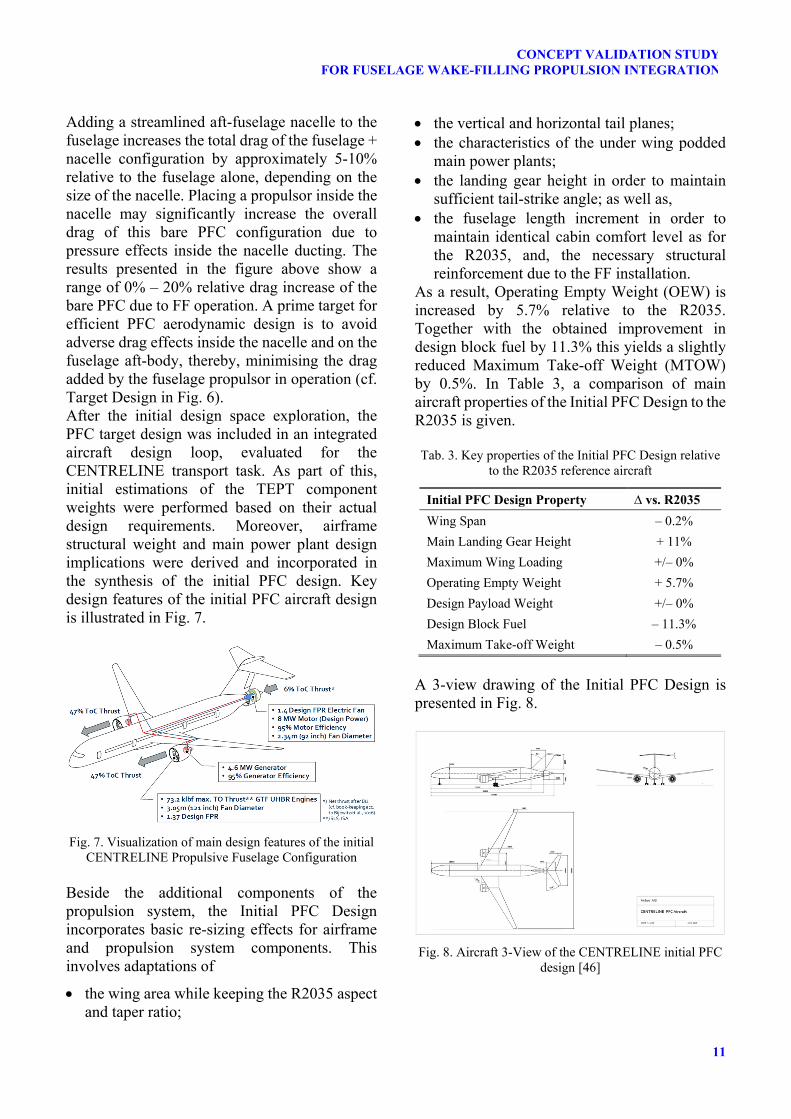
Adding a streamlined aft-fuselage nacelle to the fuselage increases the total drag of the fuselage + nacelle configuration by approximately 5-10% relative to the fuselage alone, depending on the size of the nacelle. Placing a propulsor inside the nacelle may significantly increase the overall drag of this bare PFC configuration due to pressure effects inside the nacelle ducting. The results presented in the figure above show a range of 0% – 20% relative drag increase of the bare PFC due to FF operation. A prime target for efficient PFC aerodynamic design is to avoid adverse drag effects inside the nacelle and on the fuselage aft-body, thereby, minimising the drag added by the fuselage propulsor in operation (cf. Target Design in Fig. 6). After the initial design space exploration, the PFC target design was included in an integrated aircraft design loop, evaluated for the CENTRELINE transport task. As part of this, initial estimations of the TEPT component weights were performed based on their actual design requirements. Moreover, airframe structural weight and main power plant design implications were derived and incorporated in the synthesis of the initial PFC design. Key design features of the initial PFC aircraft design is illustrated in Fig. 7.
Fig. 7. Visualization of main design features of the initial
CENTRELINE Propulsive Fuselage Configuration Beside the additional components of the propulsion system, the Initial PFC Design incorporates basic re-sizing effects for airframe and propulsion system components. This involves adaptations of
the wing area while keeping the R2035 aspect and taper ratio;
the vertical and horizontal tail planes; the characteristics of the under wing podded
main power plants; the landing gear height in order to maintain
sufficient tail-strike angle; as well as, the fuselage length increment in order to
maintain identical cabin comfort level as for the R2035, and, the necessary structural reinforcement due to the FF installation.
As a result, Operating Empty Weight (OEW) is increased by 5.7% relative to the R2035. Together with the obtained improvement in design block fuel by 11.3% this yields a slightly reduced Maximum Take-off Weight (MTOW) by 0.5%. In Table 3, a comparison of main aircraft properties of the Initial PFC Design to the R2035 is given. Tab. 3. Key properties of the Initial PFC Design relative
to the R2035 reference aircraft
Initial PFC Design Property ∆ vs. R2035
Wing Span – 0.2%
Main Landing Gear Height + 11%
Maximum Wing Loading +/– 0%
Operating Empty Weight + 5.7%
Design Payload Weight +/– 0%
Design Block Fuel – 11.3%
Maximum Take-off Weight – 0.5%
A 3-view drawing of the Initial PFC Design is presented in Fig. 8.
Fig. 8. Aircraft 3-View of the CENTRELINE initial PFC
design [46]
SEITZ ET AL.
12
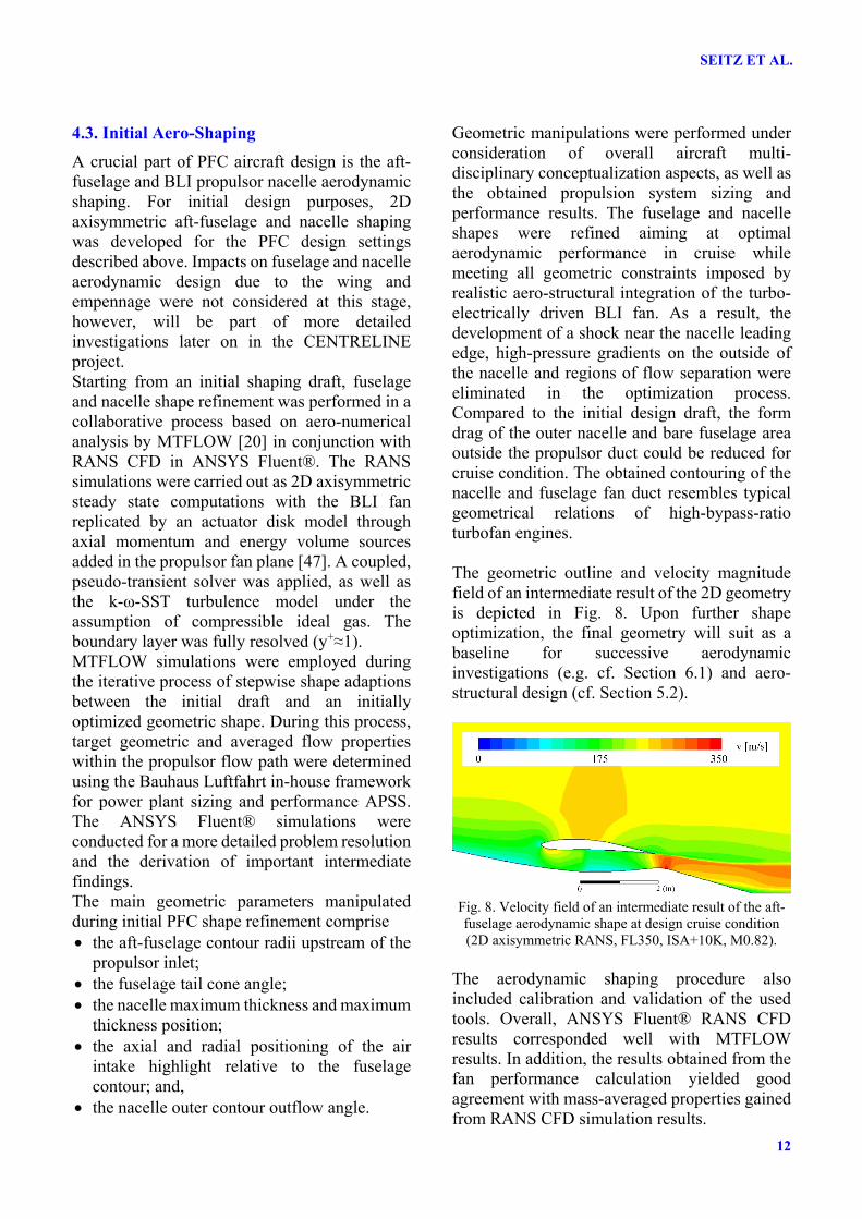
4.3. Initial Aero-Shaping
A crucial part of PFC aircraft design is the aft-fuselage and BLI propulsor nacelle aerodynamic shaping. For initial design purposes, 2D axisymmetric aft-fuselage and nacelle shaping was developed for the PFC design settings described above. Impacts on fuselage and nacelle aerodynamic design due to the wing and empennage were not considered at this stage, however, will be part of more detailed investigations later on in the CENTRELINE project. Starting from an initial shaping draft, fuselage and nacelle shape refinement was performed in a collaborative process based on aero-numerical analysis by MTFLOW [20] in conjunction with RANS CFD in ANSYS Fluent®. The RANS simulations were carried out as 2D axisymmetric steady state computations with the BLI fan replicated by an actuator disk model through axial momentum and energy volume sources added in the propulsor fan plane [47]. A coupled, pseudo-transient solver was applied, as well as the k-ω-SST turbulence model under the assumption of compressible ideal gas. The boundary layer was fully resolved (y+≈1). MTFLOW simulations were employed during the iterative process of stepwise shape adaptions between the initial draft and an initially optimized geometric shape. During this process, target geometric and averaged flow properties within the propulsor flow path were determined using the Bauhaus Luftfahrt in-house framework for power plant sizing and performance APSS. The ANSYS Fluent® simulations were conducted for a more detailed problem resolution and the derivation of important intermediate findings. The main geometric parameters manipulated during initial PFC shape refinement comprise the aft-fuselage contour radii upstream of the
propulsor inlet; the fuselage tail cone angle; the nacelle maximum thickness and maximum
thickness position; the axial and radial positioning of the air
intake highlight relative to the fuselage contour; and,
the nacelle outer contour outflow angle.
Geometric manipulations were performed under consideration of overall aircraft multi-disciplinary conceptualization aspects, as well as the obtained propulsion system sizing and performance results. The fuselage and nacelle shapes were refined aiming at optimal aerodynamic performance in cruise while meeting all geometric constraints imposed by realistic aero-structural integration of the turbo-electrically driven BLI fan. As a result, the development of a shock near the nacelle leading edge, high-pressure gradients on the outside of the nacelle and regions of flow separation were eliminated in the optimization process. Compared to the initial design draft, the form drag of the outer nacelle and bare fuselage area outside the propulsor duct could be reduced for cruise condition. The obtained contouring of the nacelle and fuselage fan duct resembles typical geometrical relations of high-bypass-ratio turbofan engines. The geometric outline and velocity magnitude field of an intermediate result of the 2D geometry is depicted in Fig. 8. Upon further shape optimization, the final geometry will suit as a baseline for successive aerodynamic investigations (e.g. cf. Section 6.1) and aero-structural design (cf. Section 5.2).
Fig. 8. Velocity field of an intermediate result of the aft-fuselage aerodynamic shape at design cruise condition (2D axisymmetric RANS, FL350, ISA+10K, M0.82).
The aerodynamic shaping procedure also included calibration and validation of the used tools. Overall, ANSYS Fluent® RANS CFD results corresponded well with MTFLOW results. In addition, the results obtained from the fan performance calculation yielded good agreement with mass-averaged properties gained from RANS CFD simulation results.

13
CONCEPT VALIDATION STUDYFOR FUSELAGE WAKE-FILLING PROPULSION INTEGRATION
5. Propulsive Fuselage Aircraft Multidisciplinary Design
Starting from the initial PFC aircraft design, the multi-partner, multi-disciplinary collaborative aircraft design and analysis process was initialised. Beside the aerodynamics and systems design aspects, this includes the aero-structural integration for the PFC aircraft.
5.1. Collaborative Workflow Framework
As a basis for an efficient, collaborative, distributed, multidisciplinary analysis and design process, a highly effective set of tools, infrastructure and processes needs to be composed. Therefore, basic requirements, common conventions, processes and infrastructure were derived based on the project organizational structure and the type of planned activities. The areas of data security, semantically correct data integration, consistency and traceability of results have been identified as of central importance. Here, the Horizon-2020 project Aircraft 3rd Generation MDO for Innovative Collaboration of Heterogeneous Teams of Experts (AGILE) [48] was considered as the state of the art in multidisciplinary aircraft design cooperation. A secure git server was set up for data exchange between the project partners. Versioning and branching guidelines have been developed to facilitate data traceability and consistency (see Fig. 9). The nomenclature of the versioning is structured by the digits, consisting of achieved milestones, major revisions and integrated data sets.
Fig. 9. Git branching and tagging systematics [49]
A consistent set of suitable formats for data exchange was defined. Accordingly, the exchange of aircraft and system parameters is done using the Extensible Markup Language
(XML). As a base format, the Common Parametric Aircraft Configuration Scheme (CPACS) published and managed by the German Aerospace Centre (DLR) is applied. For the aspects of the PFC configuration not included in this schema, a simple and flexible meta-model was designed to create custom XML parameter blocks [49].
5.2. Aero-Structural Design
Beside the aerodynamics and systems design aspects, a key element of the PFC proof-of-concept is the aero-structural integration of the BLI propulsive device. Therefore, in CENTRELINE, the most relevant aero-structural pre-design aspects for a PFC aircraft are tackled: A first task is dedicated to the aero-structural integration of the fuselage fan nacelle with the empennage and the aft-fuselage body. In a second task, the best and balanced aero-structural integration of the fuselage-wing junction is studied in order to minimise both structural weight penalties as well as adverse inflow conditions for the fuselage wake-filling propulsor in the wing wake. The first aero-structural concept for the fuselage–empennage integration is shown in Fig. 10 –loads from the empennage are transferred to the fuselage directly, omitting the fan nacelle. An important advantage of this solution consists in a lighter nacelle structure. The overall systems design, however, needs to take into account the additional impact of the vertical tail wake flow on the BLI fan.
Fig. 10. Initial proposal for the for the fuselage –
empennage aero-structural integration
Partner Branch
Master Branch
…
Integration Branch
……
Partner Branch
Timeline
1.0.0
1.0.1
1.1.0 2.0.0
1.0.2
MS 1 MS 2
1.2.1
SEITZ ET AL.
14
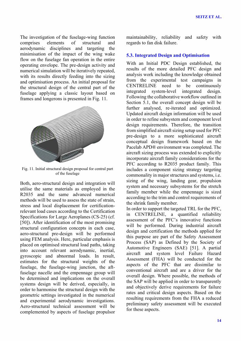
The investigation of the fuselage-wing function comprises elements of structural and aerodynamic disciplines and targeting the minimisation of the impact of the wing wake flow on the fuselage fan operation in the entire operating envelope. The pre-design activity and numerical simulation will be iteratively repeated, with its results directly feeding into the sizing and optimisation process. An initial proposal for the structural design of the central part of the fuselage applying a classic layout based on frames and longerons is presented in Fig. 11.
Fig. 11. Initial structural design proposal for central part
of the fuselage Both, aero-structural design and integration will utilise the same materials as employed in the R2035 and the same advanced numerical methods will be used to assess the state of strain, stress and local displacement for certification-relevant load cases according to the Certification Specifications for Large Aeroplanes (CS-25) (cf. [50]). After identification of the most promising structural configuration concepts in each case, aero-structural pre-design will be performed using FEM analysis. Here, particular emphasis is placed on optimised structural load paths, taking into account relevant aerodynamic, inertial, gyroscopic and abnormal loads. In result, estimates for the structural weights of the fuselage, the fuselage-wing junction, the aft-fuselage nacelle and the empennage group will be determined and implications on the overall systems design will be derived, especially, in order to harmonise the structural design with the geometric settings investigated in the numerical and experimental aerodynamic investigations. Aero-structural technical assessment will be complemented by aspects of fuselage propulsor
maintainability, reliability and safety with regards to fan disk failure.
5.3. Integrated Design and Optimisation
With an Initial PDC Design established, the results of the more detailed PFC design and analysis work including the knowledge obtained from the experimental test campaigns in CENTRELINE need to be continuously integrated system-level integrated design. Following the collaborative workflow outlined in Section 5.1, the overall concept design will be further analysed, re-iterated and optimized. Updated aircraft design information will be used in order to refine subsystem and component level design requirements. Therefore, the transition from simplified aircraft sizing setup used for PFC pre-design to a more sophisticated aircraft conceptual design framework based on the Pacelab APD® environment was completed. The aircraft sizing process was extended to explicitly incorporate aircraft family considerations for the PFC according to R2035 product family. This includes a component sizing strategy targeting commonality in major structures and systems, i.e. sizing of the wing, landing gear, propulsion system and necessary subsystems for the stretch family member while the empennage is sized according to the trim and control requirements of the shrink family member. In order to support the targeted TRL for the PFC, in CENTRELINE, a quantified reliability assessment of the PFC’s innovative functions will be performed. During industrial aircraft design and certification the methods applied for this purpose are part of the Safety Assessment Process (SAP) as Defined by the Society of Automotive Engineers (SAE) [51]. A partial aircraft and system level Failure Hazard Assessment (FHA) will be conducted for the aspects of the PFC that are dissimilar to conventional aircraft and are a driver for the overall design. Where possible, the methods of the SAP will be applied in order to transparently and objectively derive requirements for failure rates and critical design aspects. Based on the resulting requirements from the FHA a reduced preliminary safety assessment will be executed for these aspects.
15
CONCEPT VALIDATION STUDYFOR FUSELAGE WAKE-FILLING PROPULSION INTEGRATION
6. Aerodynamic Test Campaigns
The core of the aerodynamic work is formed by overall configuration wind tunnel and BLI fan rig testing campaigns.
6.1. Overall Configuration Wind Tunnel Testing
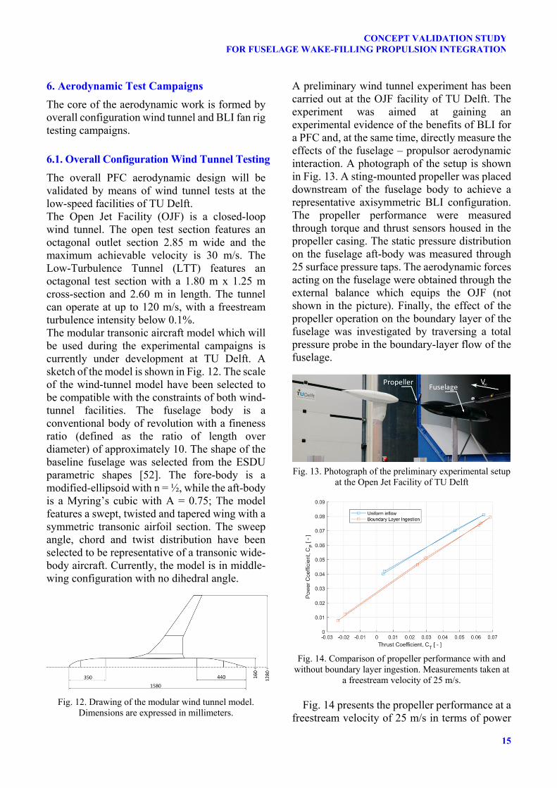
The overall PFC aerodynamic design will be validated by means of wind tunnel tests at the low-speed facilities of TU Delft. The Open Jet Facility (OJF) is a closed-loop wind tunnel. The open test section features an octagonal outlet section 2.85 m wide and the maximum achievable velocity is 30 m/s. The Low-Turbulence Tunnel (LTT) features an octagonal test section with a 1.80 m x 1.25 m cross-section and 2.60 m in length. The tunnel can operate at up to 120 m/s, with a freestream turbulence intensity below 0.1%. The modular transonic aircraft model which will be used during the experimental campaigns is currently under development at TU Delft. A sketch of the model is shown in Fig. 12. The scale of the wind-tunnel model have been selected to be compatible with the constraints of both wind-tunnel facilities. The fuselage body is a conventional body of revolution with a fineness ratio (defined as the ratio of length over diameter) of approximately 10. The shape of the baseline fuselage was selected from the ESDU parametric shapes [52]. The fore-body is a modified-ellipsoid with n = ½, while the aft-body is a Myring’s cubic with A = 0.75; The model features a swept, twisted and tapered wing with a symmetric transonic airfoil section. The sweep angle, chord and twist distribution have been selected to be representative of a transonic wide-body aircraft. Currently, the model is in middle-wing configuration with no dihedral angle.
Fig. 12. Drawing of the modular wind tunnel model.
Dimensions are expressed in millimeters.
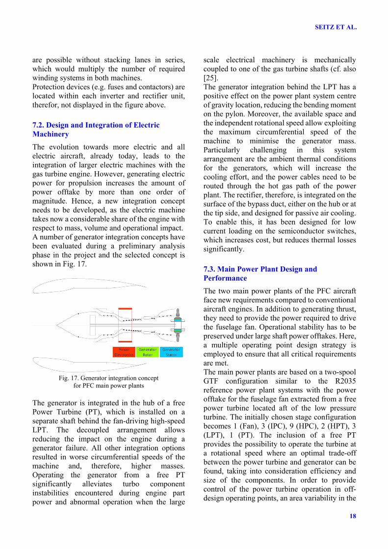
A preliminary wind tunnel experiment has been carried out at the OJF facility of TU Delft. The experiment was aimed at gaining an experimental evidence of the benefits of BLI for a PFC and, at the same time, directly measure the effects of the fuselage – propulsor aerodynamic interaction. A photograph of the setup is shown in Fig. 13. A sting-mounted propeller was placed downstream of the fuselage body to achieve a representative axisymmetric BLI configuration. The propeller performance were measured through torque and thrust sensors housed in the propeller casing. The static pressure distribution on the fuselage aft-body was measured through 25 surface pressure taps. The aerodynamic forces acting on the fuselage were obtained through the external balance which equips the OJF (not shown in the picture). Finally, the effect of the propeller operation on the boundary layer of the fuselage was investigated by traversing a total pressure probe in the boundary-layer flow of the fuselage.
Fig. 13. Photograph of the preliminary experimental setup
at the Open Jet Facility of TU Delft
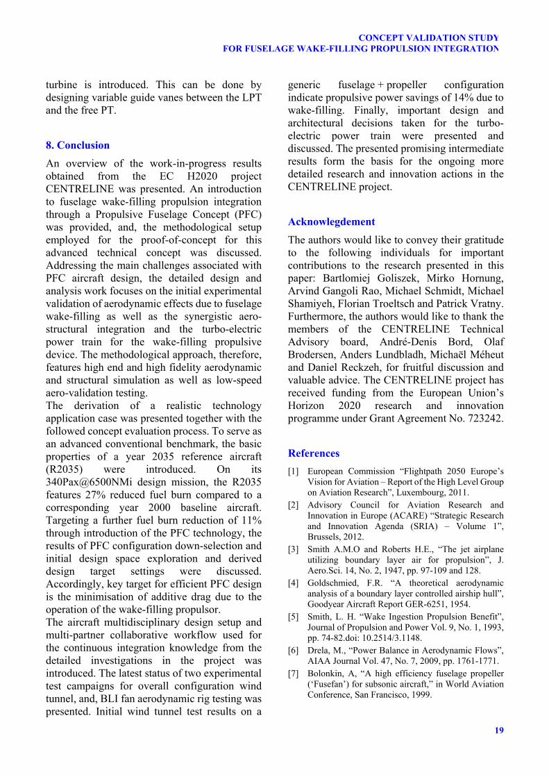
Fig. 14. Comparison of propeller performance with and
without boundary layer ingestion. Measurements taken at a freestream velocity of 25 m/s.
Fig. 14 presents the propeller performance at a
freestream velocity of 25 m/s in terms of power

SEITZ ET AL.
16
coefficient (CP) against thrust coefficient (CT). The plot compares the performance of the BLI propeller with those of the isolated propeller. The comparison shows that a power reduction of approximately 14% is achieved with BLI in representative cruise conditions.
6.2. BLI Fan Rig Testing
To study the BLI fan aerodynamics of the PFC, a detailed aerodynamic test campaign is carried out. It consists on the numerical and experimental investigation of the effect of BLI on the aerodynamic behaviour of the PFC fuselage fan performed on the low-speed BLI Fan Rig facility at the University of Cambridge. In order to gain a deeper understanding of the physics of BLI and the associated change in performance, different configurations are generated and analysed. A rig scale baseline fan system optimised for clean uniform flow constitutes the first configuration. It is designed/evaluated using steady, single-passage, GPU-accelerated CFD simulations. To be representative of a hypothetical PFC operating at the equivalent clean flow conditions as the CENTRELINE PFC, the hub-to-tip radii ratio and mean radius velocity triangles are replicated. The latter is attained matching the mean flow and stage loading coefficients. Upon the completion of the baseline design, axisymmetric, but radially non-uniform inlet boundary conditions are prescribed to analyse the effect of BLI on the propulsor. Fig. 15 presents a meridional profile sketch of this configuration subjected to non-uniform inlet conditions. Fine (I) and coarse (II) mesh regions are indicated along with the main features of the model.
Fig. 15. Meridional profile sketch of the computational
domain for the BLI rig configuration
The change in flow structures is assessed and the loss in aerodynamic performance is quantified at the same mean flow coefficient. Out of this study, a better understanding of the design philosophy required to restore the performance of the system is gained. The application of the formulated design philosophy to the first configuration results in a rig scale BLI optimised fan system. The annulus geometry is kept unchanged from the previous configuration and fan and stator blades are designed to match the prescribed velocity triangles, and therefore the desired performance. Once the fundamental understanding of the impact of BLI on the velocity triangles of the system has been gained, compressibility effects associated with BLI are studied. This is carried out by scaling the first two configurations up to full scale. The resulting configurations are dimensionally and operationally matched to the CENTRELINE PFC. The change in shockwave structure consequence of BLI is assessed, and further design rules drawn. The configurations analysed until this point have been characterised by a straight intake with axial inflow. The effect of the CENTRELINE PFC intake curvature and the associated radial velocity components is evaluated in a fifth full scale configuration. The change in flow structures is studied, and the necessary changes in blade design obtained. The progressive incorporation of compressibility and radial velocity components into the analysis enables the decoupling of the fundamental BLI velocity triangle study from these secondary effects. Additionally, it quantifies the deviation of the results obtained with the rig scale configurations from the CENTRELINE PFC configuration. The latter is particularly important as the rig scale configurations accurately replicate the experimental setup to be run during the experimental campaign. Full-annulus, unsteady CFD simulations are run to further assess the effect of non-axisymmetric distorted inflow on the performance of the PFC at cruise design conditions. These results are complemented by the experimental measurements and the necessity of a non-

17
CONCEPT VALIDATION STUDYFOR FUSELAGE WAKE-FILLING PROPULSION INTEGRATION
axisymmetric stator row matched to the incoming flow is evaluated [53]. In the last place full-annulus, unsteady CFD simulations and experimental tests are used to analyse the BLI aerodynamics of the PFC and quantify the loss in performance at relevant off design conditions.
7. Fuselage Fan Turbo-electric Powertrain
The PFC turbo-electric powertrain includes all components necessary to transport mechanical power from the two podded gas turbine engines to the fuselage fan. Beside the main power plants, the powertrain is divided in two subsystems that are of particular interest in this project: the power generation system, which includes
the podded gas turbine engine, the multi-megawatt generator, the power electronics and the cooling system; and,
the fuselage fan drive system, which includes the fuselage fan motor, the power electronics and the cooling system.
The power transmission as a third system is investigated in reduced detail as the key issues and possible showstoppers for this technology are expected in the two subsystems itemised above.
7.1. Systems Architectural Exploration
The powertrain architecture is already roughly defined by the PFC aircraft configuration. It contains one generator in each podded engine and one motor to drive the fuselage fan. An energy buffer (e.g. batteries) for in-flight propulsive power is not considered in this project. An important architectural design decision is associated with the electric power transmission type, which could be either Direct Current (DC) or Alternating Current (AC). An AC grid enables power transmission without power electronic devices, which reduces losses and system mass. On the other hand, failures during synchronizing electric machines to an AC grid can be catastrophic for the aircraft and there is only little experience on the system stability in such small AC grids. Compared to DC transmissions, AC grids require larger cables to transport reactive
power and the electric machines need to be sized bigger in order to deliver this power. Hence, a DC power transmission is chosen as the reference system. Another configuration parameter to be determined is the parallelization of the powertrain into multiple lanes. When properly designed, the electric machines allow for operation with the winding system partially inoperative. When the winding system is divided into multiple, independent winding systems, the powertrain can be divided into multiple, independent lanes. Fig. 16 shows the chosen powertrain architecture for the turbo-electric PFC in CENTRELINE with four independent lanes for each engine.
Fig. 16. Basic turbo-electric drive train architecture
The left side in Fig. 16 shows two turbines, which represent the podded engines as a power source. Each generator (GEN) is designed to provide four winding systems. Each lane has its own rectifier and inverter units. The fuselage fan motor (MOT) is designed to feature eight independent winding systems. Preliminary investigations performed by Siemens have shown that this architecture allows to reduce the failure rate for partial loss of power (2 lanes inoperative) well below 1e-9 per flight hour. Scaling effects of the power electronic hardware are negligible at this power level. Basic investigations of possible inverter topologies and standard semiconductor switches show that DC voltages from two to four kilovolts
SEITZ ET AL.
18
are possible without stacking lanes in series, which would multiply the number of required winding systems in both machines. Protection devices (e.g. fuses and contactors) are located within each inverter and rectifier unit, therefor, not displayed in the figure above.
7.2. Design and Integration of Electric Machinery
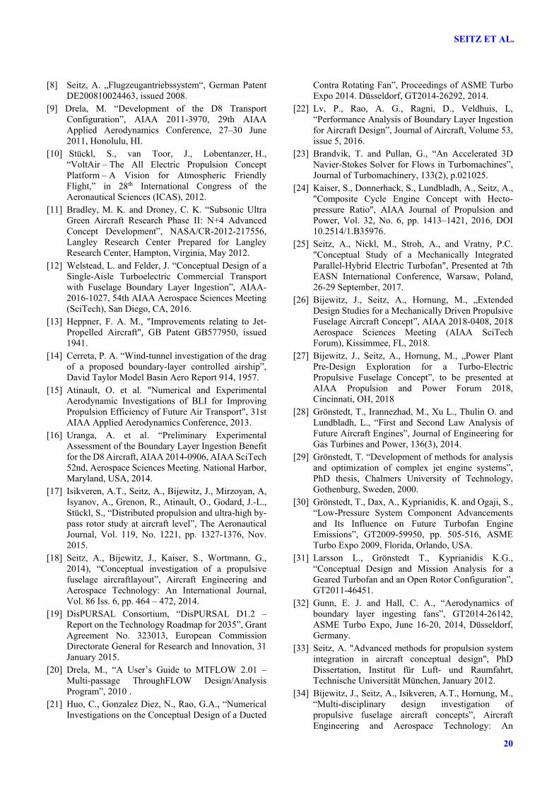
The evolution towards more electric and all electric aircraft, already today, leads to the integration of larger electric machines with the gas turbine engine. However, generating electric power for propulsion increases the amount of power offtake by more than one order of magnitude. Hence, a new integration concept needs to be developed, as the electric machine takes now a considerable share of the engine with respect to mass, volume and operational impact. A number of generator integration concepts have been evaluated during a preliminary analysis phase in the project and the selected concept is shown in Fig. 17.
Fig. 17. Generator integration concept
for PFC main power plants The generator is integrated in the hub of a free Power Turbine (PT), which is installed on a separate shaft behind the fan-driving high-speed LPT. The decoupled arrangement allows reducing the impact on the engine during a generator failure. All other integration options resulted in worse circumferential speeds of the machine and, therefore, higher masses. Operating the generator from a free PT significantly alleviates turbo component instabilities encountered during engine part power and abnormal operation when the large
scale electrical machinery is mechanically coupled to one of the gas turbine shafts (cf. also [25]. The generator integration behind the LPT has a positive effect on the power plant system centre of gravity location, reducing the bending moment on the pylon. Moreover, the available space and the independent rotational speed allow exploiting the maximum circumferential speed of the machine to minimise the generator mass. Particularly challenging in this system arrangement are the ambient thermal conditions for the generators, which will increase the cooling effort, and the power cables need to be routed through the hot gas path of the power plant. The rectifier, therefore, is integrated on the surface of the bypass duct, either on the hub or at the tip side, and designed for passive air cooling. To enable this, it has been designed for low current loading on the semiconductor switches, which increases cost, but reduces thermal losses significantly.
7.3. Main Power Plant Design and Performance
The two main power plants of the PFC aircraft face new requirements compared to conventional aircraft engines. In addition to generating thrust, they need to provide the power required to drive the fuselage fan. Operational stability has to be preserved under large shaft power offtakes. Here, a multiple operating point design strategy is employed to ensure that all critical requirements are met. The main power plants are based on a two-spool GTF configuration similar to the R2035 reference power plant systems with the power offtake for the fuselage fan extracted from a free power turbine located aft of the low pressure turbine. The initially chosen stage configuration becomes 1 (Fan), 3 (IPC), 9 (HPC), 2 (HPT), 3 (LPT), 1 (PT). The inclusion of a free PT provides the possibility to operate the turbine at a rotational speed where an optimal trade-off between the power turbine and generator can be found, taking into consideration efficiency and size of the components. In order to provide control of the power turbine operation in off-design operating points, an area variability in the
19
CONCEPT VALIDATION STUDYFOR FUSELAGE WAKE-FILLING PROPULSION INTEGRATION
turbine is introduced. This can be done by designing variable guide vanes between the LPT and the free PT.
8. Conclusion
An overview of the work-in-progress results obtained from the EC H2020 project CENTRELINE was presented. An introduction to fuselage wake-filling propulsion integration through a Propulsive Fuselage Concept (PFC) was provided, and, the methodological setup employed for the proof-of-concept for this advanced technical concept was discussed. Addressing the main challenges associated with PFC aircraft design, the detailed design and analysis work focuses on the initial experimental validation of aerodynamic effects due to fuselage wake-filling as well as the synergistic aero-structural integration and the turbo-electric power train for the wake-filling propulsive device. The methodological approach, therefore, features high end and high fidelity aerodynamic and structural simulation as well as low-speed aero-validation testing. The derivation of a realistic technology application case was presented together with the followed concept evaluation process. To serve as an advanced conventional benchmark, the basic properties of a year 2035 reference aircraft (R2035) were introduced. On its 340Pax@6500NMi design mission, the R2035 features 27% reduced fuel burn compared to a corresponding year 2000 baseline aircraft. Targeting a further fuel burn reduction of 11% through introduction of the PFC technology, the results of PFC configuration down-selection and initial design space exploration and derived design target settings were discussed. Accordingly, key target for efficient PFC design is the minimisation of additive drag due to the operation of the wake-filling propulsor. The aircraft multidisciplinary design setup and multi-partner collaborative workflow used for the continuous integration knowledge from the detailed investigations in the project was introduced. The latest status of two experimental test campaigns for overall configuration wind tunnel, and, BLI fan aerodynamic rig testing was presented. Initial wind tunnel test results on a
generic fuselage + propeller configuration indicate propulsive power savings of 14% due to wake-filling. Finally, important design and architectural decisions taken for the turbo-electric power train were presented and discussed. The presented promising intermediate results form the basis for the ongoing more detailed research and innovation actions in the CENTRELINE project.
Acknowlegdement
The authors would like to convey their gratitude to the following individuals for important contributions to the research presented in this paper: Bartlomiej Goliszek, Mirko Hornung, Arvind Gangoli Rao, Michael Schmidt, Michael Shamiyeh, Florian Troeltsch and Patrick Vratny. Furthermore, the authors would like to thank the members of the CENTRELINE Technical Advisory board, André-Denis Bord, Olaf Brodersen, Anders Lundbladh, Michaël Méheut and Daniel Reckzeh, for fruitful discussion and valuable advice. The CENTRELINE project has received funding from the European Union’s Horizon 2020 research and innovation programme under Grant Agreement No. 723242.
References
[1] European Commission “Flightpath 2050 Europe’s Vision for Aviation – Report of the High Level Group on Aviation Research”, Luxembourg, 2011.
[2] Advisory Council for Aviation Research and Innovation in Europe (ACARE) “Strategic Research and Innovation Agenda (SRIA) – Volume 1”, Brussels, 2012.
[3] Smith A.M.O and Roberts H.E., “The jet airplane utilizing boundary layer air for propulsion”, J. Aero.Sci. 14, No. 2, 1947, pp. 97-109 and 128.
[4] Goldschmied, F.R. “A theoretical aerodynamic analysis of a boundary layer controlled airship hull”, Goodyear Aircraft Report GER-6251, 1954.
[5] Smith, L. H. “Wake Ingestion Propulsion Benefit”, Journal of Propulsion and Power Vol. 9, No. 1, 1993, pp. 74-82.doi: 10.2514/3.1148.
[6] Drela, M., “Power Balance in Aerodynamic Flows”, AIAA Journal Vol. 47, No. 7, 2009, pp. 1761-1771.
[7] Bolonkin, A, “A high efficiency fuselage propeller (‘Fusefan’) for subsonic aircraft,” in World Aviation Conference, San Francisco, 1999.
SEITZ ET AL.
20
[8] Seitz, A. „Flugzeugantriebssystem“, German Patent DE200810024463, issued 2008.
[9] Drela, M. “Development of the D8 Transport Configuration”, AIAA 2011-3970, 29th AIAA Applied Aerodynamics Conference, 27–30 June 2011, Honolulu, HI.
[10] Stückl, S., van Toor, J., Lobentanzer, H., “VoltAir – The All Electric Propulsion Concept Platform – A Vision for Atmospheric Friendly Flight,” in 28th International Congress of the Aeronautical Sciences (ICAS), 2012.
[11] Bradley, M. K. and Droney, C. K. “Subsonic Ultra Green Aircraft Research Phase II: N+4 Advanced Concept Development”, NASA/CR-2012-217556, Langley Research Center Prepared for Langley Research Center, Hampton, Virginia, May 2012.
[12] Welstead, L. and Felder, J. “Conceptual Design of a Single-Aisle Turboelectric Commercial Transport with Fuselage Boundary Layer Ingestion”, AIAA-2016-1027, 54th AIAA Aerospace Sciences Meeting (SciTech), San Diego, CA, 2016.
[13] Heppner, F. A. M., "Improvements relating to Jet-Propelled Aircraft", GB Patent GB577950, issued 1941.
[14] Cerreta, P. A. “Wind-tunnel investigation of the drag of a proposed boundary-layer controlled airship”, David Taylor Model Basin Aero Report 914, 1957.
[15] Atinault, O. et al. "Numerical and Experimental Aerodynamic Investigations of BLI for Improving Propulsion Efficiency of Future Air Transport", 31st AIAA Applied Aerodynamics Conference, 2013.
[16] Uranga, A. et al. “Preliminary Experimental Assessment of the Boundary Layer Ingestion Benefit for the D8 Aircraft, AIAA 2014-0906, AIAA SciTech 52nd, Aerospace Sciences Meeting. National Harbor, Maryland, USA, 2014.
[17] Isikveren, A.T., Seitz, A., Bijewitz, J., Mirzoyan, A, Isyanov, A., Grenon, R., Atinault, O., Godard, J.-L., Stückl, S., “Distributed propulsion and ultra-high by-pass rotor study at aircraft level”, The Aeronautical Journal, Vol. 119, No. 1221, pp. 1327-1376, Nov. 2015.
[18] Seitz, A., Bijewitz, J., Kaiser, S., Wortmann, G., 2014), “Conceptual investigation of a propulsive fuselage aircraftlayout”, Aircraft Engineering and Aerospace Technology: An International Journal, Vol. 86 Iss. 6, pp. 464 – 472, 2014.
[19] DisPURSAL Consortium, “DisPURSAL D1.2 – Report on the Technology Roadmap for 2035”, Grant Agreement No. 323013, European Commission Directorate General for Research and Innovation, 31 January 2015.
[20] Drela, M., “A User’s Guide to MTFLOW 2.01 – Multi-passage ThroughFLOW Design/Analysis Program”, 2010 .
[21] Huo, C., Gonzalez Diez, N., Rao, G.A., “Numerical Investigations on the Conceptual Design of a Ducted
Contra Rotating Fan”, Proceedings of ASME Turbo Expo 2014. Düsseldorf, GT2014-26292, 2014.
[22] Lv, P., Rao, A. G., Ragni, D., Veldhuis, L, “Performance Analysis of Boundary Layer Ingestion for Aircraft Design”, Journal of Aircraft, Volume 53, issue 5, 2016.
[23] Brandvik, T. and Pullan, G., “An Accelerated 3D Navier-Stokes Solver for Flows in Turbomachines”, Journal of Turbomachinery, 133(2), p.021025.
[24] Kaiser, S., Donnerhack, S., Lundbladh, A., Seitz, A., "Composite Cycle Engine Concept with Hecto-pressure Ratio", AIAA Journal of Propulsion and Power, Vol. 32, No. 6, pp. 1413–1421, 2016, DOI 10.2514/1.B35976.
[25] Seitz, A., Nickl, M., Stroh, A., and Vratny, P.C. "Conceptual Study of a Mechanically Integrated Parallel-Hybrid Electric Turbofan", Presented at 7th EASN International Conference, Warsaw, Poland, 26-29 September, 2017.
[26] Bijewitz, J., Seitz, A., Hornung, M., „Extended Design Studies for a Mechanically Driven Propulsive Fuselage Aircraft Concept”, AIAA 2018-0408, 2018 Aerospace Sciences Meeting (AIAA SciTech Forum), Kissimmee, FL, 2018.
[27] Bijewitz, J., Seitz, A., Hornung, M., „Power Plant Pre-Design Exploration for a Turbo-Electric Propulsive Fuselage Concept”, to be presented at AIAA Propulsion and Power Forum 2018, Cincinnati, OH, 2018
[28] Grönstedt, T., Irannezhad, M., Xu L., Thulin O. and Lundbladh, L., “First and Second Law Analysis of Future Aircraft Engines”, Journal of Engineering for Gas Turbines and Power, 136(3), 2014.
[29] Grönstedt, T. “Development of methods for analysis and optimization of complex jet engine systems”, PhD thesis, Chalmers University of Technology, Gothenburg, Sweden, 2000.
[30] Grönstedt, T., Dax, A., Kyprianidis, K. and Ogaji, S., “Low-Pressure System Component Advancements and Its Influence on Future Turbofan Engine Emissions”, GT2009-59950, pp. 505-516, ASME Turbo Expo 2009, Florida, Orlando, USA.
[31] Larsson L., Grönstedt T., Kyprianidis K.G., “Conceptual Design and Mission Analysis for a Geared Turbofan and an Open Rotor Configuration”, GT2011-46451.
[32] Gunn, E. J. and Hall, C. A., “Aerodynamics of boundary layer ingesting fans”, GT2014-26142, ASME Turbo Expo, June 16-20, 2014, Düsseldorf, Germany.
[33] Seitz, A. "Advanced methods for propulsion system integration in aircraft conceptual design", PhD Dissertation, Institut für Luft- und Raumfahrt, Technische Universität München, January 2012.
[34] Bijewitz, J., Seitz, A., Isikveren, A.T., Hornung, M., “Multi-disciplinary design investigation of propulsive fuselage aircraft concepts”, Aircraft Engineering and Aerospace Technology: An

21
CONCEPT VALIDATION STUDYFOR FUSELAGE WAKE-FILLING PROPULSION INTEGRATION
International Journal, Vol. 88 Iss. 2 pp. 257-267, 2016.
[35] Seitz, A., Isikveren, A.T., Bijewitz, J., Mirzoyan, A., Isyanov, A., Godard, J.-L. and Stückl, S. “Summary of Distributed Propulsion and Ultra-high By-pass Rotor Study at Aircraft Level”, Paper ID paper: 3E-1, in ‘Aviation in Europe – Innovation for Growth.', Proceedings from the Seventh European Aeronautics Days, London, 20-22 October 2015, 2017.
[36] German Aerospace Center (DLR), “CPACS - Common Parametric Aircraft Configuration Schema”, 2018. [Online]. Available: http://www.cpacs.de/. [assessed: Feb 2018].
[37] Ali, F., Ellbrant, L., Elmdahl, D., Grönstedt, T., “A Noise Assessment Framework for Subsonic Aircraft and Engines”, GT2016-58012.
[38] Grönstedt, T., Xisto, C., Sethi, V., Rolt, A., Rosa, N. G., Seitz, A., Yakinthos,K., Donnerhack, S., Newton, P., Tantot, N., Schmitz, O., Lundbladh, A., “Ultra Low Emissions Technology Innovations for Mid-Century Aircraft Turbine Engines”, GT2016-56123, ASME Turbo Expo 2016, Seoul, South Korea.
[39] Association of European Airlines "Operating Economy of AEA Airlines", 2007.
[40] Schmidt, M., Plötner, K. O., Öttl, G., Isikveren, A.T., Hornung, M., “Scenario-based life-cycle cost assessment of future air transport concepts”, International Journal of Aviation Management, Vol. 2, Nos. 3/4, 2015.
[41] Plötner, K. O., Schmidt, M., Baranowski, D., Isikveren, A.T., Hornung, M., “Operating Cost Estimation for Electric-Powered Transport Aircraft”, Aviation Technology, Integration, and Operations Conference, 2013, Los Angeles, USA, AIAA 2013-4281.
[42] Plötner, K. O., Wesseler, P., Phleps, P. “Identification of key aircraft and operational parameters affecting airport charges”, International Journal of Aviation Management, Vol. 2, Nos. 1/2, 2013, pp 91-115.
[43] Oguntona, O., Cui, A., Plötner, K. O., Hornung, M., “Fleet Development Planning of Airlines: Incorporating the Aircraft Operating Economics Factor”, 30th International Congress of the Aeronautical Sciences (ICAS), 2016.
[44] Randt, N. P., Jessberger, C., Ploetner, K. O., “Estimating the Fuel Saving Potential of Commercial Aircraft in Future Fleet-Development Scenarios”, AIAA Aviation Conference, Dallas, USA, 2015.
[45] Airbus S.A.S., “A330 – Aircraft Characteristics, Airport and Maintenance Planning”, Revision No. 24, January 2017.
[46] Meller F. and Kocvara F., “D1.02 Specification of Propulsive Fuselage Aircraft Layout and Design Features”, CENTRELINE Public Report, April 2018.
[47] Stokkermans, T.C.A., van Arnhem, N., Sinnige, T., Veldhuis, L.L.M., “Validation and Comparison of RANS Propeller Modeling Methods for Tip-Mounted
Applications”, AIAA SciTech Forum, Aerospace Sciences Meeting, Kissimmee, Florida, USA, 2018.
[48] Ciampa, P. D., Nagel, B., “The AGILE Paradigm: the next generation of collaborative MDO,“ in 18th AIAA/ISSMO Multidisciplinary Analysis and Optimization Conference, Denver, Colorado, 2017.
[49] Shamiyeh, M., “D2.01 Definition of Multidisciplinary Interfacing Strategy”, CENTRELINE Public Project Report D2.01, April 2018.
[50] Goraj, Z., Goliszek, B., Kowalski , M., Seitz, A., Peter, F., Kocvara, F., “Strategy and Implementation of a Parametric CAD Model for R2035 Aircraft Structure and External Configuration”, Proc. 31 ICAS Congress, Belo Horizonte, Brazil, 09-14 September 2018.
[51] SAE ARP 4761 “Guidelines and Methods for Conducting the Safety Assessment Process on Civil Airborne Systems and Equipment”, Society of Automotive Engineers, 1996.
[52] Chappell, P. D., Clarke, A. J. and Porter, R., “Geometrical characteristics of typical bodies.”, IHS ESDU 77028, 1977.
[53] Gunn, E. J. and Hall, C. A, “Non-axisymmetric Stator Design of Boundary Layer Ingeting Fans”, GT2017-63082, ASME Turbo Expo, June 16-30, 2017, Charlotte, North Carolina, USA.
Contact Author Email Address
Copyright Statement
The authors confirm that they, and/or their company or organization, hold copyright on all of the original material included in this paper. The authors also confirm that they have obtained permission, from the copyright holder of any third party material included in this paper, to publish it as part of their paper. The authors confirm that they give permission, or have obtained permission from the copyright holder of this paper, for the publication and distribution of this paper as part of the ICAS proceedings or as individual off-prints from the proceedings.