conceptual engineering report final · pdf file6. suspension bridge design features ... the...
TRANSCRIPT

DETROIT RIVER INTERNATIONAL CROSSING
BRIDGE CONCEPTUAL ENGINEERING REPORT
NOVEMBER 2007
REV 1 – FEBRUARY 2008 PREPARED BY:
PARSONS
A BORDER TRANSPORTATION PARTNERSHIP

Detroit River International Crossing Bridge Conceptual Engineering Report
February 2008
Conceptual Engineering Report_Final_080211.doc
(This page is intentionally blank)
Detroit River International Crossing Bridge Conceptual Engineering Report
February 2008
Conceptual Engineering Report_Final_080211.doc Page i
Table of Contents 1. EXECUTIVE SUMMARY.................................................................................................................. 1
1.1. INTRODUCTION............................................................................................................................. 1 1.2. DESIGN CRITERIA ......................................................................................................................... 1 1.3. COST ESTIMATE & SCHEDULE....................................................................................................... 1 1.4. CONCEPTUAL ENGINEERING KEY FINDINGS .................................................................................. 2
2. INTRODUCTION............................................................................................................................... 3 2.1. PROJECT BACKGROUND................................................................................................................ 3
3. REPORT SCOPE................................................................................................................................ 3 3.1. CROSSING LOCATIONS .................................................................................................................. 4 3.2. BRIDGE ALTERNATIVES ................................................................................................................. 4
4. DESIGN PARAMETERS AND APPROACH ................................................................................... 5 4.1. GEOMETRIC DEVELOPMENT.......................................................................................................... 5 4.2. DESIGN LOADS AND FORCES ......................................................................................................... 6 4.3. ANALYSIS...................................................................................................................................... 7 4.4. MATERIALS ................................................................................................................................... 8 4.5. DESIGN CRITERIA ......................................................................................................................... 8
5. DESCRIPTION OF ALTERNATIVES ............................................................................................. 8 5.1. ALIGNMENT X-10(B) – SUSPENSION BRIDGE ALTERNATIVE (OPTION 7).......................................... 8 5.2. ALIGNMENT X-10(B) – CABLE-STAYED BRIDGE ALTERNATIVE (OPTION 4) ..................................... 9 5.3. ALIGNMENT X-11(C) – SUSPENSION BRIDGE ALTERNATIVE (OPTION 10) ....................................... 9 5.4. ALIGNMENT X-11(C) – CABLE-STAYED BRIDGE ALTERNATIVE (OPTION 9) ..................................... 9
6. SUSPENSION BRIDGE DESIGN FEATURES............................................................................. 10 6.1. TOWERS...................................................................................................................................... 10 6.2. ANCHORAGES ............................................................................................................................. 10 6.3. DECK SYSTEM / STIFFENING ELEMENT ........................................................................................ 10 6.4. MAIN CABLES AND SUSPENDERS.................................................................................................. 10
7. CABLE-STAYED DESIGN FEATURES........................................................................................ 10 7.1. FOUNDATIONS ............................................................................................................................ 10 7.2. PYLONS ...................................................................................................................................... 10 7.3. ANCHOR PIERS ........................................................................................................................... 11 7.4. DECK SYSTEM............................................................................................................................. 11 7.5. STAY CABLES .............................................................................................................................. 11
8. PROPOSED CONSTRUCTION METHODS.................................................................................. 11 8.1. SUSPENSION BRIDGE ALTERNATIVES............................................................................................ 11
8.1.1. Tower Foundations..................................................................................................... 11 8.1.2. Towers ........................................................................................................................ 11 8.1.3. Anchorage Foundations.............................................................................................. 12 8.1.4. Anchorages................................................................................................................. 12 8.1.5. Suspension System ..................................................................................................... 12 8.1.6. Orthotropic Box Girder Fabrication ........................................................................... 12 8.1.7. Orthotropic Box Girder Erection................................................................................ 13 8.1.8. Deck Finishes ............................................................................................................. 13
8.2. CABLE STAYED ALTERNATIVES .................................................................................................... 13 8.2.1. Pylon Foundations ...................................................................................................... 13 8.2.2. Pylons ......................................................................................................................... 13
8.2.3. Anchor Piers................................................................................................................13 8.2.4. Cable System ..............................................................................................................14 8.2.5. Concrete Box Girder ...................................................................................................14 8.2.6. Orthotropic Box Girder Fabrication............................................................................14 8.2.7. Orthotropic Box Girder Erection.................................................................................14 8.2.8. Deck Finishes..............................................................................................................14
9. QUANTITY AND COST ESTIMATES............................................................................................14 9.1. COST ESTIMATE BASIS AND ASSUMPTIONS....................................................................................14 9.2. INITIAL CONSTRUCTION COST......................................................................................................15 9.3. LIFE CYCLE COST .......................................................................................................................15 9.4. RISKS AND RISK ASSESSMENT.......................................................................................................15
10. CONSIDERATIONS FOR SUBSEQUENT DEVELOPMENT......................................................16 10.1. NEW MATERIALS .........................................................................................................................16 10.2. SUBSURFACE INVESTIGATIONS .....................................................................................................16 10.3. FOUNDATION TYPES....................................................................................................................16 10.4. AERODYNAMIC STABILITY INVESTIGATIONS...................................................................................16 10.5. INSPECTION ACCESS....................................................................................................................16 10.6. DURABILITY ................................................................................................................................16 10.7. STRUCTURAL MONITORING..........................................................................................................17 10.8. SECURITY/HARDENING ................................................................................................................17
APPENDIX A: DRAWINGS
APPENDIX B: CONSTRUCTION SCHEDULES
APPENDIX C: DETAILED COST ESTIMATES
Table of Figures FIGURE 1: AREA OF CONTINUED ANALYSIS ................................................................................................3 FIGURE 2: CROSSING ALIGNMENTS .............................................................................................................4 FIGURE 3: NAVIGATION ENVELOPE.............................................................................................................5 FIGURE 4: PROPOSED BRIDGE CROSS SECTION ...........................................................................................5 FIGURE 5: FUTURE DESIGN ALLOWANCE CROSS SECTION..........................................................................6

Detroit River International Crossing Bridge Conceptual Engineering Report
February 2008
Conceptual Engineering Report_Final_080211.doc 1
1. Executive Summary
1.1. Introduction This report documents the development of the four bridge options advanced through the Conceptual Engineering (CE) phase (Table 1). These bridge options represent components of the Practical Alternatives for crossings X-10(B) and X-11(C) (Figure 2). A third horizontal alignment, X-10(A), was developed in the Type Study phase to avoid the area around a known sinkhole from historical brine mining in Canada if necessary. The Type Study demonstrated that Crossing X-10(A) is not preferred from a bridge engineering perspective, therefore advancing conceptual engineering of bridge options at X-10(A) was postponed until preliminary results are obtained from the geotechnical investigation program and any other relevant project EA/EIS studies. A final recommendation from the geotechnical investigation program is not expected until after this report is published. The scope of this Bridge Conceptual Engineering Report is to document the development process for the main bridge crossing the Detroit River, discuss the options developed, evaluate the technical merits of those options, and provide input into the evaluation of the Practical Alternatives. For the recommended project alternative, or Preferred Alternative, two bridge types, suspension and cable-stayed, will be advanced for further development in the Early Preliminary Engineering phase.
1.2. Design Criteria The main river crossing structure is subject to the design codes of both the U.S. and Canada and the project has been developed using the International System of Units (SI units). The design shall meet the requirements of the AASHTO LRFD Bridge Design Specifications, SI Units, 4th Edition, and the Canadian Highway Bridge Design Code, CAN/CSA S6-06 (S6). In general the more restrictive code shall govern. In the CE phase the predominant site constraints are the required navigation envelope and horizontal alignment that avoids major industries while connecting to the Toll and Inspection Plazas. The third major component is the bridge cross section. These are shown in Figures 4 and 5, for the initial configuration and a possible future configuration, respectively. The bridges are designed to clear span the Detroit River with a clearance of 40.54 m at the river’s edge. The proposed cross section consists of six lanes with shoulders and a 1 m flush median. A TL-5 barrier is proposed. The bridge is designed for future restriping to accommodate eight lanes with a median barrier. The design life, for statistical assessment of appropriate loads, shall be 75 years in accordance with AASHTO LRFD Bridge Design Specifications Article 1.2 – Definitions. The service life for assessing serviceability of all components shall be 120 years. For specific components where it is not practicable to achieve a 120 year life, these components shall be designed with the ability to be replaced.
Table 1. Conceptual Engineering Options.
Conceptual Engineering Option Elevation CE Option X-10(B)
Option 4
Option 7
X-11(C)
Option 9
Option 10
1.3. Cost Estimate & Schedule The basis of the cost estimating for this report is on a unit-price type estimate. The unit price values were derived from a combination of historical unit price information from other similar projects and project specific price information from potential suppliers. The unit prices for major items such as steel and concrete were verified with labor, equipment and material based estimates (contractor style estimate). This review focused on the large cost elements to assure that the complexities of this project, current market conditions, and the bi-national nature of the project had been properly accounted for in the unit price development. The quantities for each of the unit price items were developed based on the level of conceptual engineering performed for the structure options. The conceptual engineering focused on the development of the principal structure member sizes (primary load path definition) based on computer analysis of the structure under a limited number of loadings that were judged as the controlling load cases. Table 2 presents the construction cost estimates.
Detroit River International Crossing Bridge Conceptual Engineering Report
February 2008
Conceptual Engineering Report_Final_080211.doc 2
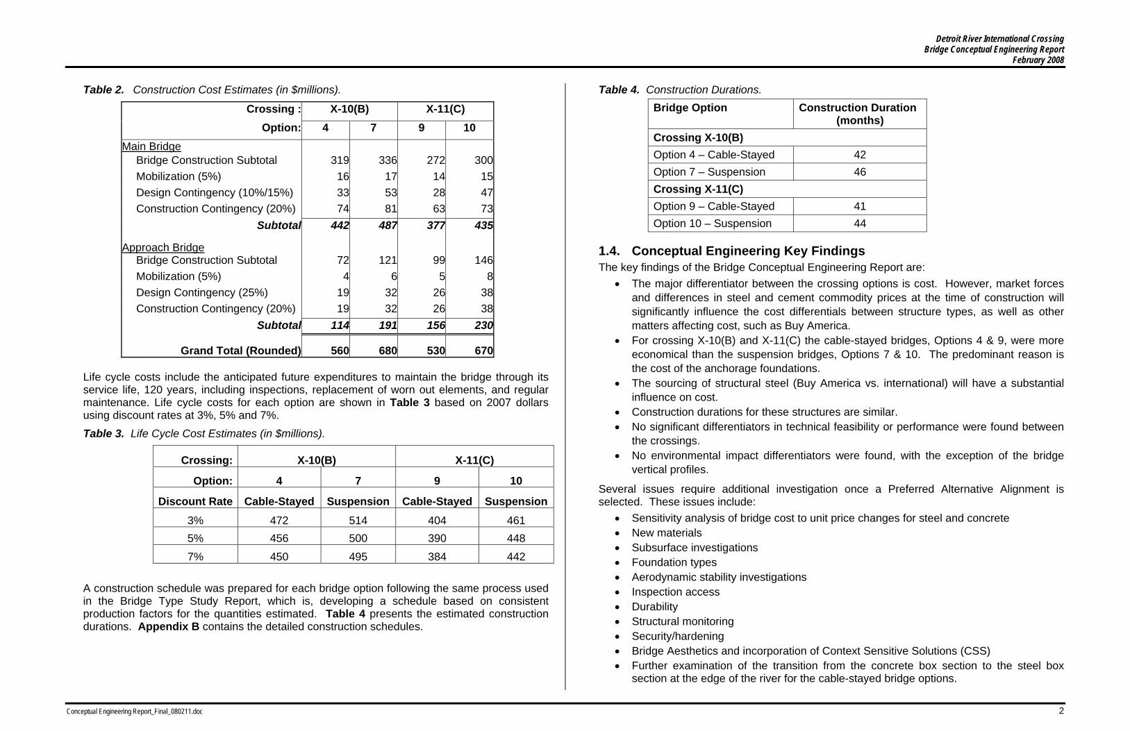
Table 2. Construction Cost Estimates (in $millions).
Crossing : X-10(B) X-11(C) Option: 4 7 9 10 Main Bridge Bridge Construction Subtotal 319 336 272 300 Mobilization (5%) 16 17 14 15 Design Contingency (10%/15%) 33 53 28 47 Construction Contingency (20%) 74 81 63 73 Subtotal 442 487 377 435
Approach Bridge Bridge Construction Subtotal 72 121 99 146 Mobilization (5%) 4 6 5 8 Design Contingency (25%) 19 32 26 38 Construction Contingency (20%) 19 32 26 38
Subtotal 114 191 156 230
Grand Total (Rounded) 560 680 530 670 Life cycle costs include the anticipated future expenditures to maintain the bridge through its service life, 120 years, including inspections, replacement of worn out elements, and regular maintenance. Life cycle costs for each option are shown in Table 3 based on 2007 dollars using discount rates at 3%, 5% and 7%. Table 3. Life Cycle Cost Estimates (in $millions).
Crossing: X-10(B) X-11(C)
Option: 4 7 9 10
Discount Rate Cable-Stayed Suspension Cable-Stayed Suspension3% 472 514 404 461 5% 456 500 390 448
7% 450 495 384 442
A construction schedule was prepared for each bridge option following the same process used in the Bridge Type Study Report, which is, developing a schedule based on consistent production factors for the quantities estimated. Table 4 presents the estimated construction durations. Appendix B contains the detailed construction schedules.
Table 4. Construction Durations. Bridge Option Construction Duration
(months) Crossing X-10(B) Option 4 – Cable-Stayed 42 Option 7 – Suspension 46 Crossing X-11(C) Option 9 – Cable-Stayed 41 Option 10 – Suspension 44
1.4. Conceptual Engineering Key Findings The key findings of the Bridge Conceptual Engineering Report are:
• The major differentiator between the crossing options is cost. However, market forces and differences in steel and cement commodity prices at the time of construction will significantly influence the cost differentials between structure types, as well as other matters affecting cost, such as Buy America.
• For crossing X-10(B) and X-11(C) the cable-stayed bridges, Options 4 & 9, were more economical than the suspension bridges, Options 7 & 10. The predominant reason is the cost of the anchorage foundations.
• The sourcing of structural steel (Buy America vs. international) will have a substantial influence on cost.
• Construction durations for these structures are similar. • No significant differentiators in technical feasibility or performance were found between
the crossings. • No environmental impact differentiators were found, with the exception of the bridge
vertical profiles.
Several issues require additional investigation once a Preferred Alternative Alignment is selected. These issues include:
• Sensitivity analysis of bridge cost to unit price changes for steel and concrete • New materials • Subsurface investigations • Foundation types • Aerodynamic stability investigations • Inspection access • Durability • Structural monitoring • Security/hardening • Bridge Aesthetics and incorporation of Context Sensitive Solutions (CSS) • Further examination of the transition from the concrete box section to the steel box
section at the edge of the river for the cable-stayed bridge options.

Detroit River International Crossing Bridge Conceptual Engineering Report
February 2008
Conceptual Engineering Report_Final_080211.doc 3
2. Introduction
2.1. Project Background The Border Transportation Partnership, consisting of the U.S. Federal Highway Administration, Transport Canada, Michigan Department of Transportation, and Ontario Ministry of Transportation, identified the need for a new or expanded crossing of the Detroit River in 2004. The planning process began with the identification of Illustrative Alternatives, consisting of the U.S. and Canadian approach roadways, toll/inspection plazas, and the international crossing structure. Through a comprehensive technical evaluation process, with input from the public, an Area of Continued Analysis (Figure 1) incorporating the two crossing corridors X-10 and X-11, was identified for the development of Practical Alternatives. The bridge options are being advanced through a two-step process; Phase 1 is the Bridge Type Study (TS phase); and, Phase 2 is the Bridge Conceptual Engineering (CE phase). This report documents the development of the four bridge options advanced through the CE phase (Table 5) as elements of the Practical Alternatives.
Figure 1: Area of Continued Analysis
Table 5. Conceptual Engineering Options.
Conceptual Engineering Option Elevation CE Option X-10(B)
Option 4
Option 7
X-11(C)
Option 9
Option 10
3. Report Scope The Bridge Type Study Report, dated January 2007 and revised July 2007, details the evaluation of 15 bridge types. Those bridge types were evaluated and screened down to the four recommended bridge types in Table 5. The scope of this Bridge Conceptual Engineering Report is to document the development process for the main bridge crossing the Detroit River, discuss the options developed, evaluate the technical merits of those options, and provide input into the evaluation of the Practical Alternatives. For the recommended project alternative, or Preferred Alternative, two bridge types, suspension and cable-stayed, will be advanced for further development in the Early Preliminary Engineering phase. The CE phase considers the entire crossing structure (i.e., main span and approach spans) but focuses on the main structure over the Detroit River. Other project components, such as the plazas, connecting roadways, and interchanges will be evaluated separately and are not addressed in this report.

Detroit River International Crossing Bridge Conceptual Engineering Report
February 2008
Conceptual Engineering Report_Final_080211.doc 4
In coordination with this technical process, a comprehensive Context Sensitive Solutions (CSS) process is being undertaken with the project stakeholders. The CSS process and results are detailed in the Conceptual Engineering Report. The goal of the Bridge Conceptual Engineering Report is to identify and evaluate the four bridge options advanced to this phase for consideration as elements of the Practical Alternatives. The Preferred Alternative will be selected based on a comprehensive evaluation of environmental, social, economic and technical considerations.
3.1. Crossing Locations Two crossing corridors were identified in the Illustrative Alternative phase, X-10 and X-11, which were associated with Plazas C3 and C4 in the U.S., and Plazas C2, C3, and C7 in Canada. At the beginning of the Practical Alternative phase these plaza locations were generalized into an “Area of Continued Analysis”, Figure 1 above, and revised plaza locations were identified in consultation with public stakeholders and agencies. After the refinement of the plaza locations in the U.S. and Canada the X-10 and X-11 river crossing corridors were reexamined. Based on the avoidance of major industries and cultural properties such as Brighton Beach Power Station, Mistersky Power Plant, and Fort Wayne, two horizontal alignments were developed, X-10(B) and X-11(C). A third horizontal alignment, X-10(A), was developed to avoid the area around a known sinkhole from historical brine mining in Canada if necessary. The X-10(A) alignment starts near the location of X-10(B) in the U.S. and lands in Canada south west of Brighton Beach Power Station. The three alignments are presented in Figure 2 below. Crossing X-10(A) is not preferred from a bridge engineering perspective, as detailed in the Bridge Type Study Report, therefore advancing conceptual engineering of bridge options at X-10(A) was postponed until preliminary results are obtained from the geotechnical investigation program and any other relevant project EA/EIS studies. A final recommendation from the geotechnical investigation program is not expected until after this report is published.
3.2. Bridge Alternatives In the vicinity of corridors X-10 and X-11 the Detroit River varies in width from 570 m to 790 m. Currently, major commercial shipping exists on the Detroit River as well as many shoreline industries in the project area receive delivery of goods and materials via ship. Therefore, it is necessary to provide a navigation envelope of adequate size so as not to restrict marine traffic. The options advanced from the TS phase to the CE phase include only bridges that span the entire river with a single clear span (i.e., both main towers are on the shore), based on strong objections to piers in the river from both U.S. and Canadian Lake Carriers Associations, river pilots, Transport Canada Marine Safety Division and the U.S. Coast Guard. Navigation requirements are addressed in Section 4.1. The alignments cross the river at skew angles of 25 degrees and 29 degrees for alignments X-10(B) and X-11(C), respectively (skew angle measured from a line perpendicular to the centerline of channel to centerline of bridge). The combination of skews and the requirement to clear span the river result in main span lengths 760 m or longer being considered during conceptual engineering for the Detroit River crossing. At this length the only practicable bridge types are cable-stayed and suspension bridges. Main span lengths are shown in Table 6.
Figure 2: Crossing Alignments
Table 6. Summary of Main Span Lengths and Bridge Types.
Alignment Option Main Span (m)
Bridge Type: Cable-Stayed (C) Suspension (S)
4 840 C X-10(B) 7 855 S 9 760 C X-11(C) 10 760 S
Note: Bridge option numbers have been carried forward from the Bridge Type Study Report.
Detroit River International Crossing Bridge Conceptual Engineering Report
February 2008
Conceptual Engineering Report_Final_080211.doc 5
4. Design Parameters and Approach
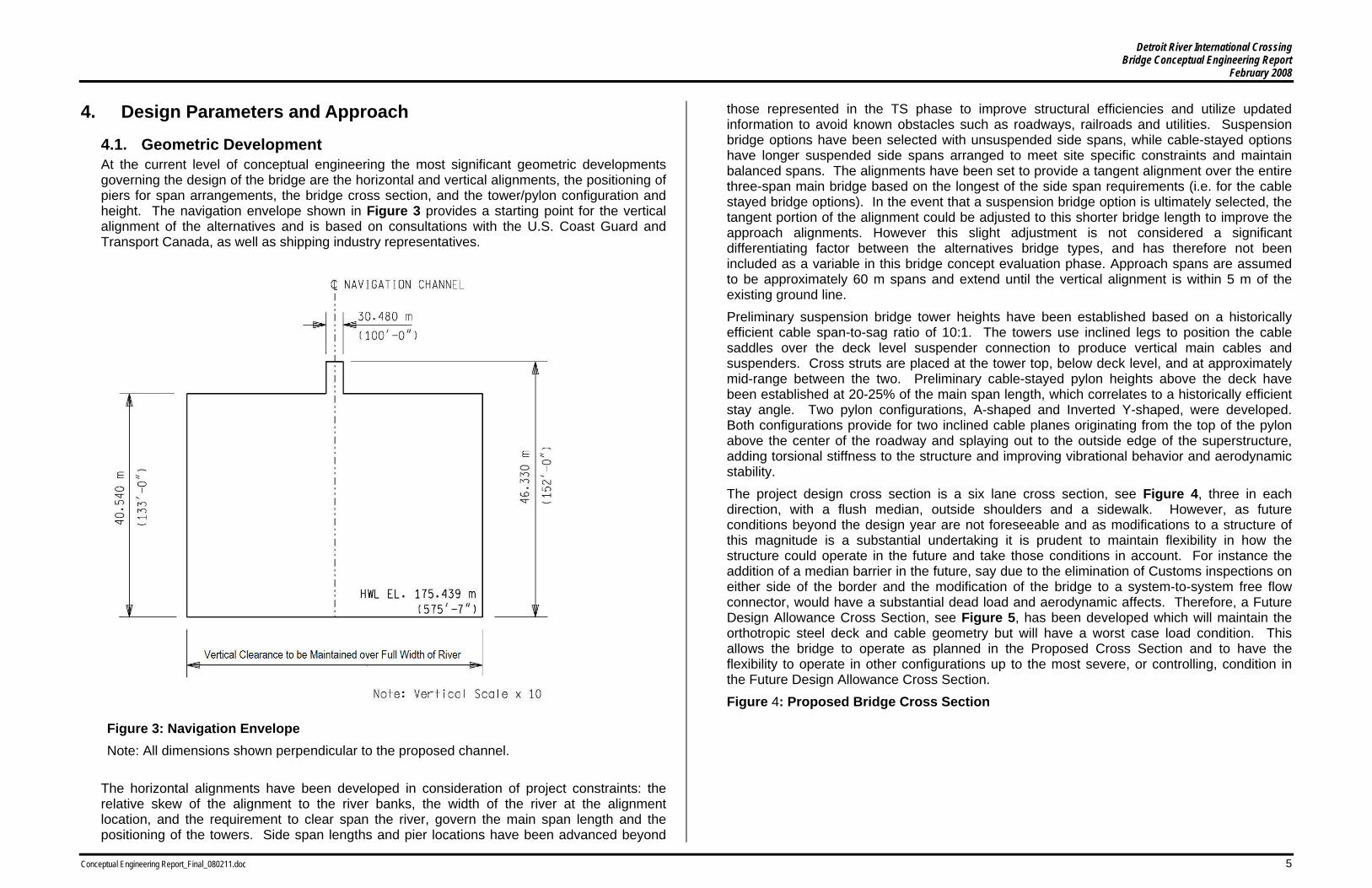
4.1. Geometric Development At the current level of conceptual engineering the most significant geometric developments governing the design of the bridge are the horizontal and vertical alignments, the positioning of piers for span arrangements, the bridge cross section, and the tower/pylon configuration and height. The navigation envelope shown in Figure 3 provides a starting point for the vertical alignment of the alternatives and is based on consultations with the U.S. Coast Guard and Transport Canada, as well as shipping industry representatives.
Figure 3: Navigation Envelope Note: All dimensions shown perpendicular to the proposed channel.
The horizontal alignments have been developed in consideration of project constraints: the relative skew of the alignment to the river banks, the width of the river at the alignment location, and the requirement to clear span the river, govern the main span length and the positioning of the towers. Side span lengths and pier locations have been advanced beyond
those represented in the TS phase to improve structural efficiencies and utilize updated information to avoid known obstacles such as roadways, railroads and utilities. Suspension bridge options have been selected with unsuspended side spans, while cable-stayed options have longer suspended side spans arranged to meet site specific constraints and maintain balanced spans. The alignments have been set to provide a tangent alignment over the entire three-span main bridge based on the longest of the side span requirements (i.e. for the cable stayed bridge options). In the event that a suspension bridge option is ultimately selected, the tangent portion of the alignment could be adjusted to this shorter bridge length to improve the approach alignments. However this slight adjustment is not considered a significant differentiating factor between the alternatives bridge types, and has therefore not been included as a variable in this bridge concept evaluation phase. Approach spans are assumed to be approximately 60 m spans and extend until the vertical alignment is within 5 m of the existing ground line. Preliminary suspension bridge tower heights have been established based on a historically efficient cable span-to-sag ratio of 10:1. The towers use inclined legs to position the cable saddles over the deck level suspender connection to produce vertical main cables and suspenders. Cross struts are placed at the tower top, below deck level, and at approximately mid-range between the two. Preliminary cable-stayed pylon heights above the deck have been established at 20-25% of the main span length, which correlates to a historically efficient stay angle. Two pylon configurations, A-shaped and Inverted Y-shaped, were developed. Both configurations provide for two inclined cable planes originating from the top of the pylon above the center of the roadway and splaying out to the outside edge of the superstructure, adding torsional stiffness to the structure and improving vibrational behavior and aerodynamic stability. The project design cross section is a six lane cross section, see Figure 4, three in each direction, with a flush median, outside shoulders and a sidewalk. However, as future conditions beyond the design year are not foreseeable and as modifications to a structure of this magnitude is a substantial undertaking it is prudent to maintain flexibility in how the structure could operate in the future and take those conditions in account. For instance the addition of a median barrier in the future, say due to the elimination of Customs inspections on either side of the border and the modification of the bridge to a system-to-system free flow connector, would have a substantial dead load and aerodynamic affects. Therefore, a Future Design Allowance Cross Section, see Figure 5, has been developed which will maintain the orthotropic steel deck and cable geometry but will have a worst case load condition. This allows the bridge to operate as planned in the Proposed Cross Section and to have the flexibility to operate in other configurations up to the most severe, or controlling, condition in the Future Design Allowance Cross Section. Figure 4: Proposed Bridge Cross Section

Detroit River International Crossing Bridge Conceptual Engineering Report
February 2008
Conceptual Engineering Report_Final_080211.doc 6
The bridge cross section was developed dependent on the roadway cross section and cable clearance. Actual cable-to-cable dimensions may vary for the cable-stayed options due to individual inclined cable geometry. The Future Design Allowance Cross Section, which represents the controlling condition, is used for the conceptual engineering phase of the project.
Figure 5: Future Design Allowance Cross Section
The suspension bridge superstructures consist of an orthotropic steel box girder in the main span with unsuspended concrete box girder approach spans. The cable-stayed superstructures also consist of an orthotropic steel box girder for the majority of the main span. Reinforced concrete box girders are utilized near the pylons and in the side spans. The cable-stayed orthotropic steel box girder is heavier and varying in section to accommodate the compressive loads imparted by the stays.
4.2. Design Loads and Forces Design loads and forces for the conceptual engineering analysis are based on the design codes of both the U.S. and Canada. Material densities/weights for common structural materials are shown in Table 7. The superstructure design was advanced as a steel orthotropic box girder in the main span of both bridge types and a concrete box girder in the cable-stayed side spans, and was analyzed for global loadings.
Table 7. Weights.
Material Density Reinforced Concrete 2400 kg/m3 (150 lb/ft3)
Structural Steel 7850 kg/m3 (490 lb/ft3) Stay Cable Strand
(greased and sheathed) 1.22 kg/m (0.82 lb/ft)
(15.2 mm ø Seven-Wire Strand)
HDPE Stay Pipe Varies (See Table 10)
The superimposed dead loads listed in Table 8 are applied to all structures. Table 8. Superimposed Dead Loads.
Superimposed Dead Load
Unit Weight
[Item] [kN/m] Overlay 35.5 Traffic Barrier – Median 11.0 Traffic Barriers –
Exterior 14.5
Traveler Rails 3.0 Lighting 0.5 Drainage 4.0 Paint 1.0 Utilities 4.0 Total 73.5
The current design code live loads do not apply to structures beyond 152 m (500 ft). As a result, applying AASHTO lane loadings would be overly conservative. Table 9 reflects loading applied to the recently completed Carquinez and Tacoma Narrows Bridges and is used during this conceptual engineering. AASHTO Table 3.6.1.1.2-1 Multiple Presence Factors shall be applied as appropriate. It is recommended that a detailed study be performed for development of final design to determine appropriate loading conditions. In addition to normal loading conditions, considerations should also be given to unique operational conditions such as multiple lane loadings for trucks, similar to what was done for the Blue Water Bridge.
Table 9. AASHTO Lane Loads Modified for Long Spans.
Loaded Length, L (m)
Uniform Load (kN/m/lane)
Concentrated Load at center of loaded
length (kN/lane) 0 < L ≤ 185 9.34 (HL-93) 115.7 (HL-93)

Detroit River International Crossing Bridge Conceptual Engineering Report
February 2008
Conceptual Engineering Report_Final_080211.doc 7
185 < L < 365 11.73 – L/77.25 145.5 – L/6.21
365 ≤ L 7.01 86.7
Earthquake loadings are not considered in the conceptual engineering phase. The low seismic zone indicates a low probability that seismic concerns will control the design other than specific components that are beyond the scope of this phase of the work. Furthermore, at this level of design, qualitative comparative statements between crossing locations (X-10(B) versus X-11(C)) concerning earthquake loading will not likely yield differentiating design characteristics or costs. Wind loads are anticipated to be the critical loading condition for design of specific elements of the cable-stayed options. However, due to the conceptual stage of development, only limited analysis was performed consisting of the static wind load evaluation of the tower/pylon in response to transverse winds. It is recommended that a preliminary level of wind tunnel analysis of the proposed structure and a determination of local climatology conditions should be performed in the next design phase. Force effects from temperature were determined using LRFD Section 3.12.2, Procedure A, with a standard design temperature of 15°C and the following AASHTO Cold Climate Temperature ranges:
Steel = -35°C / +50°C (-20°C to 65°C) & Concrete = -18°C / +27°C (-3°C to 42°C).
Other loading conditions such as Stream Flow / Scour, Vessel Collision, and Ice Accretion are not considered in this phase as none of the four alternatives under consideration have marine piers. However, Ice Accretion may be considered in future phases.
4.3. Analysis The four bridge options advanced through the conceptual engineering phase were analyzed using two-dimensional non-linear structural analysis computer software to determine preliminary member sizing based on the geometry, loads, forces, materials, and design criteria. The analysis consisted of a final static state analysis of the structure including dead loads, live load analysis and thermal loads. A detailed analysis of local effects in members, construction loading conditions, and dynamic effects of wind were not considered at this stage of conceptual design. The following Strength Limit State load combinations were considered for designing the box girders, towers/pylons, stay cables, and foundations:
Strength 1a – 1.0 [1.25 DC + 1.25 DW + 1.75 LL + 1.20 TU] & Strength 1b – 1.0 [0.90 DC + 0.90 DW + 1.75 LL – 1.20 TU], where
DC = Dead load of structural components and non-structural attachments,
DW = Dead load wearing surface and utilities,
LL = Vehicular live load, &
TU = Uniform temperature.
The STRENGTH III load combination in Table 3.4.1-1 of the AASHTO LRFD Bridge Design Specifications is considered in this study for wind loads. The following Service Limit State combination was considered for designing the suspension bridge suspenders, main cables, and anchorages only: Service V – 1.0 [1.0 DC + 1.0 DW + 1.0 LL + 1.0 TU]. The following live load loaded length scenarios were analyzed in the model: 1. Entire structure loaded 2. Main span only loaded 3. 50% of the main span loaded 4. Both side spans loaded The concrete and steel box girder superstructures were designed to withstand the demands from the Strength Limit States. Stay cable quantities were determined based on results from the Strength Limit States in conformance with the PTI Guide Specification Recommendations for Stay Cable Design, Testing and Installation, 4th Edition and Addendum 1 thereof. The self weight of the stay cables and stay pipe is included in the compressive loads applied to the pylon and deck superstructure. Stay sizes and stay pipe sizes and weights are included in Table 10. Steel frame anchorages in the top of the pylon were determined based on splitting and vertical forces as determined from the Strength Limit States. An assumed anchor detail at the deck level based on other cable-stayed bridge examples was used to determine rough quantities. Suspension system quantities were determined based on results from the Service Limit State. Suspenders were designed with a Factor of Safety = 4.0 against the catalogue breaking strength. Main cables were designed to a stress level of 690 MPa (100 ksi), with a void ratio of 19% to size cable bands and saddles. Cable Bands, Saddles, and Anchor Frame sizes and quantities were determined based on a comparative evaluation of similar structures. Strand Shoes have a minimum bend radius of 230 mm and Anchor Rods were designed to ASTM A434 Class BD Material at a stress level of 345 MPa (50 ksi) on the tensile stress area (approximately 0.5Fy). Tower/pylon cross sections were initially sized and reinforcement determined for the demands of the Strength Limit States. Reinforcement was refined on a percentage basis, based on engineering judgment and an evaluation of similar structures. Similarly, the effect of lateral loads on the cross section was based on demands from the Strength Limit States including wind, structural analysis of the tower/pylon capacity and engineering judgment considering an evaluation of similar existing structures. Drilled caissons for the towers/pylons and anchor piers were sized based on the above Strength Limit States. Suspension bridge anchorages have a Factor of Safety of 2.0 against overturning and sliding with at-rest soil pressures.

Detroit River International Crossing Bridge Conceptual Engineering Report
February 2008
Conceptual Engineering Report_Final_080211.doc 8
Table 10. Stay Sizes and Stay Pipe HDPE Tube Sizes & Weights.
Stay Size (number of
strands)
Outer Diameter
(mm)
Thickness (mm)
Stay Pipe Weight (kg/m)
12 125 4.9 1.88 19 140 5.4 2.32 31 160 6.2 3.04 37 180 5.6 3.12 55 200 6.2 3.84 61 225 7.0 4.84 73 250 7.8 5.99 91 280 8.7 7.47
4.4. Materials The following materials and properties were assumed for the analysis and conceptual design of the bridge structure components: Reinforcing – fy = 415 MPa (60 ksi) Concrete Box Girder Concrete – f’c = 45 MPa (6500 psi) Tower/Pylon Concrete – f’c = 45 MPa (6500 psi) Foundation/Anchorage Concrete – f’c = 28 MPa (4000 psi) Structural Steel – Fy = 345 MPa (50 ksi) Stay Cable Strand
15.2 mm ø Seven-Wire Strand (0.6 inch ø) Ultimate Strength, fpu = 1,860 MPa (270 ksi) Strand Area = 140 mm2 (0.217 in2)
4.5. Design Criteria The main river crossing structure is subject to the design codes of both the U.S. and Canada and the project has been developed using the International System of Units (SI units). The design shall meet the requirements of the AASHTO LRFD Bridge Design Specifications, SI Units, 4th Edition, and the Canadian Highway Bridge Design Code, CAN/CSA S6-06 (S6), and in general the more restrictive code shall govern. It should be noted that the Michigan Department of Transportation has discontinued producing or maintaining SI unit design guides, therefore, conversions will be made from U.S. Standard Units as needed. The following documents are used in the development of the Detroit River International Crossing Conceptual Design Phase:
AASHTO, A Policy on Geometric Design of Highways and Streets, 2004. AASHTO LRFD Bridge Design Specifications, SI Units, 4th Edition and all Interim Revisions.
AASHTO, Standard Specifications for Structural Supports for Highway Signs, Luminaires, and Traffic Signals, 4th Edition and all Interim Revisions. Canadian Highway Bridge Design Code, CAN/CSA S6-06. Geometric Design Standards for Ontario (GDSOH). MDOT – Bridge Design Guide http://mdotwas1.mdot.state.mi.us/public/design/bridgeguides/. MDOT – Bridge Design Manual http://mdotwas1.mdot.state.mi.us/public/design/englishbridgemanual/.
MDOT – Standard Plans http://mdotwas1.mdot.state.mi.us/public/design/englishstandardplans/index.htm.
PTI, Recommendations for Stay Cable Design, Testing and Installation, 4th Edition, 2001 and 2004 Addendum 1.
The design life, for statistical assessment of appropriate loads, shall be 75 years in accordance with AASHTO LRFD Bridge Design Specifications Article 1.2 – Definitions. The service life for assessing serviceability of all components shall be 120 years. For specific components where it is not practicable to achieve a 120 year life, these components shall be designed with the ability to be replaced. Examples of such components include, but are not limited to: stay cables, bearings, expansion joints, deck wearing surface, navigation lighting, and roadway lighting. The bridge components requiring replacement shall be identified and included in the life cycle bridge cost evaluation. The design shall provide multiple load paths and the structure shall be continuous to achieve redundancy. Non-redundant members shall be detailed to provide internal redundancy where practicable. The operational importance of the bridge shall be classified as “important”. For seismic design purposes the bridge shall be classified as “critical”.
5. Description of Alternatives
5.1. Alignment X-10(B) – Suspension Bridge Alternative (Option 7) The suspension bridge alternate at crossing X-10(B) consists of an 855 m suspended main span and 253 m (US) and 244 m (Canada) unsuspended backstay spans. The stiffening element consists of a 3.25 m deep orthotropic steel box girder. The girder is supported at 12 m intervals by wire rope suspenders connected to the main cables. The main cables are comprised of 37 strands of 412 wires each, for a total of 15,244 galvanized 5 mm diameter (No. 6) wires. The cables are cradled in cast-steel saddles at the anchor splay and tower tops and are secured to the anchor blocks via cast-steel strand shoes. The towers extend 141 m above their footings and are of reinforced concrete design with three post-tensioned struts connecting the legs below the roadway deck, at the tower top, and midway between. The Detroit tower is situated on land and adjacent to the river to clear the rail spur immediately south of, and servicing the LaFarge Concrete plant. The Windsor tower is sited on land within the Southwestern Sales property. The tower legs maintain a constant

Detroit River International Crossing Bridge Conceptual Engineering Report
February 2008
Conceptual Engineering Report_Final_080211.doc 9
width for economy in forming, but vary in depth to accommodate loads that increase near the tower base. The tower legs are hollow (single cell) in cross section, allowing for access and maintenance from footing level to the uppermost strut. The gravity anchorages at each end of the bridge resist the suspension cable pull through a combination of self weight, passive soil resistance and direct load transfer to bedrock. The Detroit anchorage is situated to the north of the service road adjacent to the LaFarge Concrete plant. The Windsor anchorage has been placed in an aggregate storage facility site owned by Southwestern Sales.
5.2. Alignment X-10(B) – Cable-Stayed Bridge Alternative (Option 4) The cable-stayed option at crossing X-10(B) consists of an 840 m main span with symmetric 320 m side spans. The side span deck and the ends of the main span deck consist of a 3.5 m cast-in-place concrete box girder, supported by stay cables and side span piers at 80 m spacing. The center 630 m of main span deck consists of a 3.5 m deep orthotropic steel box girder supported by the stay cables. The stay cable spacing in the side span is 12.5 m and in the mainspan 15 m. The heavier concrete box girder allows the side spans to be shorter than one half the main span length. They act as counterweights when the main span is loaded with traffic, thus eliminating uplift on the anchor piers. Since there is no need to span large distances in the side spans, a continuous beam with relatively short spans is provided, which results in the side span cables acting as anchoring back stay cables. The side spans can be constructed on falsework in advance of the main span construction and will therefore provide a significant contribution to the stability of the main span construction under the free-cantilever erection conditions. The stay cables are connected to the orthotropic steel box girder using a stay anchor weldment. The stay anchors terminate below deck level when connected to the concrete box girder. They react against a concrete block and are cast integrally with the concrete girder. At the pylon tops, stays terminate in structural steel reaction blocks cast into and integral with the pylon walls. Two pylon configurations have been developed: an A-frame shape, as well as an inverted Y configuration. Both pylon alternatives extend 250 m above their footings, with the stays terminating within the upper 67.5 m with a stay spacing of 2.5 m in the pylon head. The pylons are of reinforced concrete design with a single cross strut below deck level. The pylon legs vary in cross section in a linear fashion simplifying forming. A hollow center is maintained, allowing for access and maintenance from footing level to the uppermost stay. The Detroit pylon is situated on land and adjacent to the river to clear the rail spur immediately south of, and servicing the LaFarge Concrete plant. The Windsor pylon is sited on land within the Southwestern Sales property. Side span support piers consist of twin solid reinforced concrete columns with hammerhead pier caps.
5.3. Alignment X-11(C) – Suspension Bridge Alternative (Option 10) The suspension bridge alternate at crossing X-11(C) consists of a 760 m suspended main span and 190 m unsuspended backstay spans. The stiffening element consists of a 3.5 m
deep orthotropic steel box girder. The girder is supported at 12 m intervals by wire rope suspenders connected to the main cables. The main cables are comprised of 37 strands of 350 wires each, for a total of 12,950 galvanized 5 mm diameter (No. 6) wires. The cables are cradled in cast-steel saddles at the anchor splay and tower tops and are secured to the anchor blocks via cast-steel strand shoes. The towers extend 130 m above their footings and are of reinforced concrete design with two post-tensioned struts connecting the legs below the roadway deck and at the tower top. The Detroit tower and anchorage are situated on land in a largely undeveloped plot formerly owned by the Detroit Coke plant. The Windsor tower and anchorage are situated on land owned by Windsor Port Authority and leased to Sterling Marine Fuels. The Canadian side spans and approaches span over an active marine fueling facility and a separate risk assessment was undertaken to confirm the acceptability of this alignment. The tower legs maintain a constant width for economy in forming, but vary in depth to accommodate loads that increase near the tower base. The tower legs are hollow (single cell) in cross section, allowing for access and maintenance from footing level to the uppermost strut. The gravity anchorages at each end of the bridge resist the suspension cable pull through a combination of self weight, passive soil resistance and direct load transfer to bedrock.
5.4. Alignment X-11(C) – Cable-Stayed Bridge Alternative (Option 9) The cable-stayed option at crossing X-11(C) consists of a 760 m main span with 300 m side spans. The side span deck and the ends of the main span deck consist of a 3.25 m deep cast-in-place concrete box girder, supported by stay cables at 14 m intervals and anchor piers at 60 m spacing. The center 660 m of the main span deck consists of a 3.25 m deep orthotropic steel box girder supported by the stay cables spaced at 18 m. The heavier concrete box girder allows the side spans to be shorter than one half the main span length. They act as counterweights when the main span is loaded with traffic, thus eliminating uplift on the anchor piers. Since there is no need to span large distances in the side spans, a continuous beam with relatively short spans is provided, which results in the side span cables acting as anchoring back stay cables. The stay cables are connected to the orthotropic steel box girder above deck level using a fin-type stay anchor welded to the steel box girder. The stay anchors terminate below deck level when connected to the concrete box girder. They react against a concrete block and are cast integrally with the concrete girder. At the pylon tops, stays terminate in structural steel reaction blocks cast into and integral with the pylon walls. Two pylon configurations have been developed: an A-frame shape, as well as an inverted Y configuration. Both pylon alternatives extend 215 m above their footings, with the stays terminating within the upper 44 m. The pylons are of reinforced concrete design with a single post-tensioned cross strut below deck level. The pylon legs vary in cross section in a linear fashion simplifying forming. A hollow center is maintained, allowing for access and maintenance from footing level to the uppermost stay. The Detroit pylon is situated on land in a largely undeveloped plot formerly owned by the Detroit Coke plant. The Windsor pylon is situated on land leased to Sterling Marine Fuels. The Canadian side spans and approaches

Detroit River International Crossing Bridge Conceptual Engineering Report
February 2008
Conceptual Engineering Report_Final_080211.doc 10
span over an active marine fueling facility and a separate risk assessment was undertaken to confirm the acceptability of this alignment. The anchor piers consist of twin reinforced concrete columns on drilled shaft foundations and are spaced to avoid Jefferson Avenue on the Detroit side.
6. Suspension Bridge Design Features
6.1. Towers The suspension bridge towers are constructed of reinforced 45 MPa concrete. Mild steel reinforcement (415 MPa) is used throughout; though higher strength steel may be used to reduce rebar congestion during final design development. The tower legs are hollow box sections. Cross struts are hollow in cross section allowing access between tower legs. Cross struts are constructed of reinforced (415 MPa) and post-tensioned (1,860 MPa) concrete (45 MPa). Access along the tower legs is typically provided by an elevator within one tower leg and a combination of stairs and fixed ladders in the other leg. Lighting is typically provided within the towers to light the access structures. The tower legs rest atop solid pedestals, which in turn are fixed to a pile-supported footing. The footing is of mass concrete (28 MPa). The piles are 3.0 m (Option 7) and 2.5 m (Option 10) diameter drilled shafts, with 16 mm thick steel stay-in-place casings. Extensive rock sockets are not anticipated, though removal of any weathered rock at the rock-soil interface may be necessary.
6.2. Anchorages Both anchorages consist of a plinth to support the splay saddles at the front face of the anchorage where both cables enter the anchorage, a splay chamber for each cable where the cable strands diverge to their respective strand shoes/anchor rods, and a mass concrete anchor block. The anchorages are gravity-type anchorages and use mass concrete to resist the pull of the main cables. For this concept level of development, it is assumed that the anchorage will be a gravity type anchorage extending into rock. The anchorage foundation is assumed to be constructed as an open dredged caisson founded on bedrock similar to the nearby Ambassador Bridge. Longitudinal resistance to the cable pull is provided by a combination of direct transfer to bedrock and conservative assumptions of the passive soil resistance. The anchorages represent a significant portion of the cost of the suspension bridge alternatives. The limited geotechnical information available at this time and the relatively poor soil conditions for the alluvial soils overlying bedrock have resulted in the anchorage design being based on conservative assumptions. It is possible that with further geotechnical information in the vicinity of the anchorages, and by exploring more economical structural configurations and construction methods, a more economical anchorage may be developed. Considering the cost implications of this design element, it is recommended that refinement of the anchorage be a focus in the next phase of design.
6.3. Deck System / Stiffening Element The stiffening element is a steel orthotropic box girder. The box girder is 36.4 m wide and continuous from tower to tower. The steel skin is stiffened longitudinally with trapezoidal steel ribs welded to the steel skin. The trapezoidal ribs are hermetically sealed and pressure tested to preclude corrosion. Open (flat plate) stiffeners are used at the tips of the girder due to space constraints. The girder is also stiffened transversely with bulkheads at 6 m spacing. The bulkheads are provided with portals for access as well as chases to allow for utilities. The steel is anticipated to be 350 MPa, ASTM A709 bridge steel. Field splices of the steel skin are welded complete joint penetration welds. Field splices of the ribs may be either welded or bolted.
6.4. Main Cables and Suspenders The main cables are comprised of galvanized 5 mm diameter (No. 6) parallel steel wires (1620 MPa). The wires are constructed using air-spinning techniques to form 37 individual strands, which are then compacted and banded to form a circular cross section. Cast steel cable bands are clamped around the cable to maintain the shape of the cable and to receive the suspender ropes. The suspender ropes are fabricated of galvanized, high-strength wire rope that has been prestretched and socketed with cast steel terminations. The suspender ropes and box girder are designed such that the suspender ropes at an isolated location can be removed for inspection, maintenance or replacement without closing the bridge to traffic. Once the full weight of the bridge is hanging from the suspender ropes, the main cable wires are coated with a waterproofing paste, helically wound wrapping wire, and a three coat, highly elastic paint system for corrosion protection. The suspender ropes receive the same coating system as the main cable. Handropes are attached above the main cable to facilitate inspection and maintenance.
7. Cable-Stayed Design Features
7.1. Foundations Deep foundations are required to carry the very heavy loads from the pylons down into bedrock. Drilled large diameter concrete filled shafts are assumed. The drilled shafts extend through the upper fill, silty clay, granular soil layers, hardpan soils, and be founded into the underlying limestone bedrock formations. The competent rock layer is located approximately 30 m below the Detroit River HWL.
7.2. Pylons Two alternative pylon shapes were investigated. A-frame and inverted Y shaped pylons were chosen to limit second order effects and to increase the structural capacity to resist wind forces. These pylon shapes also provide additional bridge torsional rigidity. The cable-stayed bridge pylons are constructed of reinforced 45 MPa concrete. Mild steel reinforcement (415 MPa) is used throughout. The pylon legs are hollow box sections.

Detroit River International Crossing Bridge Conceptual Engineering Report
February 2008
Conceptual Engineering Report_Final_080211.doc 11
A cross strut located below the deck is hollow in cross section allowing access between pylon legs. Cross struts are constructed of reinforced (415 MPa) and post-tensioned (1,860 MPa) concrete (45 MPa). Access along the pylon legs is typically provided by an elevator within one pylon leg and a combination of stairs and fixed ladders in the other leg. Lighting is typically provided within the pylons to light the access structures. The pylon legs rest atop a drilled shaft supported footing. The footing is of mass concrete (28 MPa). The drilled shafts are 2.5 m (Option 4) or 3.0 m (Option 9) diameter drilled caissons, with 16 mm steel stay-in-place casings and 415 MPa reinforcing. Extensive rock sockets are not anticipated, though removal of any weathered rock at the rock-soil interface may be necessary.
7.3. Anchor Piers Since there is no need to span large distances in the side spans, a continuous beam with relatively short spans is provided which results in all the side span cables acting as anchoring back stays cables. In addition, the recommended side span superstructure is concrete to take advantage of the heavy mass to anchor the main span superstructure which minimizes the uplift in the anchor piers. The additional side span piers will also function to stiffen the structure for live load deflections for the main span, and will contribute to stiffening the structure during the erection stage in response to wind and erection loadings. The anchor piers are constructed of reinforced 45 MPa concrete. Mild steel reinforcement (415 MPa) is used throughout.
7.4. Deck System The deck system has been designed to minimize wind forces on the superstructure and to provide a high torsional rigidity. This cross section can also accommodate both steel and concrete construction. The center of the main span is a steel orthotropic box girder. The steel box girder is 35.2 m wide and continuous with the concrete box superstructure. The steel skin is stiffened and connected as described in Section 6.3. Outside of the center mainspan section, the deck system consists of a cast-in-place concrete box girder that is constructed of reinforced (415 MPa) and post-tensioned (1,860 MPa) concrete (45 MPa).
7.5. Stay Cables The stays consist of 7-wire prestressing strands (1,860 MPa) protected individually with grease or wax and polyethylene sheathing. Individual stays are made up of multiple strands encased in a high density polyethylene pipe. An outer helical bead is placed on the pipe to prevent rain and wind induced vibrations. The strands are anchored using wedges seated in an anchor head and each strand is stressed individually with a monostrand jack. Typically an additional reference strand is installed in select stays. These reference strands can be removed and inspected at a later date. It is possible to remove and replace individual strands at any point in the life of the structure.
8. Proposed Construction Methods
8.1. Suspension Bridge Alternatives
8.1.1. Tower Foundations The tower foundations consist primarily of drilled shafts and a footing. The footing in turn consists of a pile cap at the base of each tower leg and a tie beam connecting the two pile caps. Construction methods involve conventional techniques for drilled shafts of this size. Large diameter steel casings are drilled into the soil until they come to rest on competent rock – anticipated at approximately 30 m below existing grade. Once founded on rock, the soil inside the casing is excavated by auger. With the soil excavated, prefabricated reinforcing steel cages are lowered into the casing. Reinforcing extends beyond the casing top to provide continuity with the cast-in-place footing. Cast-in-place concrete pumped into the casing completes the pile. Of note are the limited site constraints at the Detroit tower at crossing X-10(B) due to the proximity of the existing rail spur to the north and the sheet pile sea wall to the south. It is also unknown at this time if the sheet pile sea wall utilizes tie backs that would need to be addressed if they interfere with the new piles. The footing (pile caps and tie beam) consist of regularly reinforced mass concrete. Both pile caps and the tie beam are cast in a single monolithic pour at each tower. The X-10(B) Detroit tower has an advantage for such work in that it is situated adjacent to the LaFarge concrete operation. With the exception of the large quantities necessary for the monolithic pour, the footing construction utilizes conventional techniques. The footing is currently shown to be entirely below grade, though this could be revisited to potentially reduce excavation costs.
8.1.2. Towers The towers consist of three main structural elements: The tower pedestals, tower legs, and cross struts. The tower pedestal sits atop and is reinforced to be integral with the footings. The pedestals consist of reinforced cast-in-place concrete and are solid in section. Conventional construction techniques are used. The tower legs are hollow in section and consist of reinforced cast-in-place concrete. The towers are typically constructed using jump form technology. Reinforcing can be prefabricated off-site as much as practicable and placed by crane. Concrete can be placed by pump truck for the initial stages, though with the increasing height of later stages, concrete is typically placed by bucket, delivered by tower crane. Reinforcing congestion, particularly where reinforcing and prestressing strands from the tower struts frame into the tower legs, can be overcome with proper detailing. As the tower legs extend higher, they may be subject to problematic wind conditions, particularly vortex shedding, which may require mitigating measures. As an example, on the recent Tacoma Narrows Bridge, a temporary steel strut was fastened between the tower legs to overcome wind vibrations.

Detroit River International Crossing Bridge Conceptual Engineering Report
February 2008
Conceptual Engineering Report_Final_080211.doc 12
Tower struts are hollow in cross section and are of reinforced and post-tensioned concrete. The struts are typically formed in several slabs/lifts using conventional means, though providing support can be achieved by various methods. The middle and upper struts are supported by temporary beams connected to the tower legs. The lower strut may be supported in a similar manner, or via shoring supported directly on the tower footing. Post-tensioning tendons extend through the strut walls and top and bottom slabs and are anchored to the outside face of the tower legs. Once the towers have topped out, in preparation for receiving the main cables and deck, they are pulled back towards the anchorage, such that the weight of the main span will pull the towers back to plumb. Pull back operations consist of anchoring strands to the tower tops and tensioning the strands with tackle secured to the anchorages.
8.1.3. Anchorage Foundations The anchorage foundations have been designed in a manner similar to the nearby Ambassador Bridge. The anchorage foundations consist of longitudinal shear walls constructed using open dredge caisson techniques. The method involves the construction of a steel cutting edge atop which reinforced concrete walls are constructed. The walls will be configured in such a manner to create a series of open cells through which the soil may be excavated by clamshell buckets. A combination of the removal of soil and increasing weight of the rising walls forces the cutting edge to slice through the soil. The process is continued until the cutting edge reaches bedrock. With access to bedrock, the surface can be cleaned, a shear key created, and a seal-slab poured. The caisson type foundation was selected due to the limited available soil information of soil properties. The method has been proven at the Ambassador Bridge and will perform as designed nearly independent of the surrounding soil. It is recommended that the next phase of the project include subsurface testing to determine soil properties for the selected crossing so the foundation type may be revisited with the goal of selecting the most cost effective foundation solution.
8.1.4. Anchorages Anchorage construction consists of mass concrete pours, wall construction and slab construction, all of which can be accomplished with conventional construction techniques for the respective methods. Heat generated during the mass concrete pours can often be mitigated through pour sequencing without the need of special features or operations. Incorporated into the anchorage are anchorage points for the suspension system as well as several construction aids. These include the anchor rods and anchor frames, splay saddles, catwalk strand anchors, and tower pull back strand anchors. An access chamber is maintained at the back of the anchor frames throughout construction and in-filled after erection of the superstructure.
8.1.5. Suspension System When the towers are complete and the anchorage construction advanced far enough to receive suspension system components, construction of the suspension system can begin. Anchor frames and grout tubes are installed in the anchorage as anchorage work progresses. Preparatory work also includes the installation of the tower and splay saddles
at the tower tops and anchorages, respectively. Anchor rods are installed within the grout tubes at the anchorage splay chambers and strand shoes affixed thereto. To provide access for cable spinning operations, a catwalk is erected from anchorage to anchorage and follows the free cable profile. The catwalk system is comprised of several support and hand strands, open mesh flooring and sides, frames at regular intervals, and several cross bridges between cables. A storm system is provided to stabilize the footwalk in high winds and provide for profile adjustment as necessary. Custom equipment will be required at both tower tops, the splay saddles and the strand shoes to adjust the strands. A reeling plant will transfer the cable wires from coils that are delivered to the site to reels for cable spinning. The spinning equipment includes counterweight towers, drive systems, reeling plant, haul ropes, spinning wheels and all related appurtenances. Once the catwalk and spinning equipment is in place, spinning operations begin. The main cables are constructed of galvanized high-strength steel wire, air-spun, into thirty-seven (37) strands in a hexagonal pattern formed on the point of the hex. The wire is delivered in coils from the manufacturing plant and reeled and spliced on large capacity reels for spinning operations. The wires are pulled across the span with a spinning wheel connected to haul lines suspended above the free cable profile. Each wire is looped around a semi-circular cast steel strand shoe connected to the anchor rods. Once spun, each strand is formed and bound with binding straps and individually adjusted. The hexagonal configuration of the strands of the finished cable are hydraulically compacted into a single circular bundle to receive the cast steel cable bands and later, after erection of the deck and appurtenances, coated in zinc-rich paste, wrapped and painted. The wrapping wires are installed to a predefined minimum tension using one or more production wrapping machines. The wire is delivered in coils and must be reeled onto bobbins in the field or in a local reeling plant. The mechanically powered wrapper places the wire in a helical pattern tightly against one another for the full length between each cable band. At the bands, the wire terminates in the caulking grooves. Intermittent wire splicing for the wrapping wire is accomplished with an electric resistance butt welder.
8.1.6. Orthotropic Box Girder Fabrication The box girder consists of a steel skin, longitudinal ribs (trapezoidal and flat plate), longitudinal bulkheads at the suspender lines and transverse bulkheads at and between each suspender location. Trapezoidal ribs are formed to tight tolerances using a brake press and are prepared with beveled edges for an 80% partial penetration groove weld to the steel skin. Because of the large quantity of 80% penetration weld, the criticality of its performance, and the inaccessibility of the backside of the weld, the process is tightly controlled with fully automatic welding gantries and proven through prototype trials prior to production. Ribs are welded to sections of the steel skin to create panels. The panels typically contain between 4 and 8 ribs. The panels are then joined in a pre-programmed sequence with the bulkheads to form a box girder segment. The segments are trial assembled on the ground to the same alignment as the final position on the bridge. In this trial assembled position the field joints are prepared for field welding

Detroit River International Crossing Bridge Conceptual Engineering Report
February 2008
Conceptual Engineering Report_Final_080211.doc 13
of the skin, bolt holes are reamed at the rib splices, geometric control points are applied to the steel, suspender pin holes are bored, and temporary construction aids are attached. The size of the segments is typically limited by transport methods and equipment used to hoist the segments into place. As an order of magnitude, it is noted that the Tacoma Narrows segments were typically on the order of 450 tonnes. While it is understood this project is intended to have a Buy-America clause limiting procurement to North American suppliers, the following discussion is provided regarding overseas procurement as related to steel fabrication, in particular. As a matter of reference, the ongoing San Francisco-Oakland Bay Bridge (SFOBB) contains an orthotropic steel girder originally intended to be procured from US suppliers. In the final analysis, however, a 400 million dollar cost savings was realized by procuring the fabricated steel from an overseas fabricator. As a matter of scale, it is noted that the SFOBB steel quantities are approximately 4 to 5 times those of the DRIC main span. While wire, wire rope and structural strands for the suspension system may be procured at competitive prices from any number of qualified suppliers around the globe, steel fabrication of the magnitude required for the superstructure will likely be more competitively priced from offshore fabricators. In fact, the Carquinez box girder and Tacoma Narrows truss were fabricated in Japan and South Korea, respectively, and transported across the Pacific Ocean as deck cargo. The cost impact of ocean access being from the Atlantic Ocean as opposed to the Pacific Ocean has not yet been analyzed, though many similar structures have been fabricated in European countries. As an alternative method, structures of this magnitude may be fabricated off-site into panels, transported to the site and the panels assembled on-site or at a nearby assembly yard. With this method, panels could be procured from any number of sources, though with certain challenges regarding fit-up, quality control, etc. Trial assembly would also take place at this on-site or nearby yard. This remains an option for this project. However, not-withstanding the discussion above, the Lions Gate Bridge reconstruction (Vancouver, British Columbia) was fabricated in Vancouver and stands as an example of a major structure having been fabricated in North America, near the bridge site.
8.1.7. Orthotropic Box Girder Erection After trial assembly, the segments are transported to the site, most likely by barge. They are hoisted into place by a pair of lifting gantries supported by, and spanning the two main cables. Lifting can be accomplished either by winches located at the tower bases with haul lines routed to the tower tops and down to the gantries, or by strand jacks mounted on the lifting gantries. In recent years, strand jacks have been the preferred option in similar situations. Once lifted into position, the weight of the segments is transferred to the permanent suspenders. Adjacent segments are connected with temporary deck-to-deck pin connections that allow the segments to rotate with respect to each other to accommodate the changing profile of the cable as additional segments are added. As the cable becomes near fully loaded, the segments are drawn into their final relative alignment with jacking frames attached to the bottom of the box girder in preparation for the field splices. The field splices consist of complete joint penetration welds of the steel skin and longitudinal
bulkheads and bolted splices for the ribs. When the splices are complete, temporary deck attachments are removed.
8.1.8. Deck Finishes With the deck complete, operations can begin to install the electrical/mechanical systems, roadway barriers, deck water proofing, wearing surfaces, etc. The roadway wearing surface typically consists of a two-lift, natural asphalt modified overlay, placed atop a two-layered, spray-applied acrylic membrane. Both are specialty items, requiring specialized equipment and planning. Advances have been made in recent years with the overlay that may allow forgoing the specialized equipment. Electrical systems have successfully been installed using galvanized rigid metal conduit, fiber reinforced epoxy conduit or, alternatively, cable trays for the main runs with conduit used in the branch lines. In detailing the support system, adequate attention to expansion capabilities is important.
8.2. Cable-Stayed Alternatives
8.2.1. Pylon Foundations As the construction methods for the suspension bridge tower foundations and the cable-stayed pylon foundations are similar, the reader is referred to Section 8.1.1, Tower Foundations, for construction methods of the cable-stayed pylon foundations.
8.2.2. Pylons The pylons consist of three main structural elements: the pylon legs, cross struts, and cable anchorages. The reader is referred to Section 8.1.2, Towers, for construction methods of the pylon legs and cross struts, as these would be similar between structure types. In addition to the discussion in Section 8.1.2, the inclination of the pylon legs would necessitate temporary steel struts between the tower legs. Also, temporary tie-downs may be necessary to overcome wind forces and vibrations during construction. The top portion of the pylon contains the anchorage zone for the stays. The resulting tensile forces from the cables in the anchorage zone can be resisted by prestressing the concrete around the anchorage or by using a steel anchor box inside the concrete pylon walls and attached through shear connectors or other means on the vertical faces. The steel anchorage box has the advantage of being fabricated in the shop in large sections containing all the supporting diaphragms and cable anchorage tubes in the correct alignment. The anchorage box sections can then be lifted into place atop the pylon, bolted together, and the remaining pylon concrete cast around the anchorage box. It is not necessary to pull back the pylons as described for the suspension towers in Section 8.1.2. The vertical position of the pylons is ensured by proper sequencing of the stay cable jacking operation.
8.2.3. Anchor Piers For the purpose of this study, the anchor pier foundations consist of drilled shafts and a footing under each pier. The construction methods involve conventional techniques for drilled shafts of this size as described above. The footing consists of regular cast-in-place
Detroit River International Crossing Bridge Conceptual Engineering Report
February 2008
Conceptual Engineering Report_Final_080211.doc 14
reinforced concrete and is currently shown to be entirely below grade. The pier construction involves solid cast-in-place reinforced concrete columns. Multiple construction lifts and splicing of column reinforcing will be required for the tall piers.
8.2.4. Cable System Due to the height of the pylon anchorage above the deck and the overall length and size of the cables, the conventional method of installing an entire full sized, shop-fabricated stay using a deck-mounted crane is likely not practicable. A more likely cable installation method for a bridge of this size is the iso-tensioning method where each strand is installed and tensioned one at a time to the same force as a reference strand. The individual strands are delivered to the site on reels and the first strand is pulled from the bridge deck to the pylon top using a winch, cut to length, tensioned to a predetermined force, and temporarily anchored. The remaining strands are then pulled along the strands that have already been tensioned and are supported by temporary stirrups attached to the tensioned strands. Each strand is tensioned when it reaches the top using a small mono-strand jack with a load cell and anchored using wedges seated in the anchor head.
8.2.5. Concrete Box Girder Outside of the center main span section, the deck system consists of a post-tensioned cast-in-place concrete box girder section cast on falsework. The construction of the side spans can be accomplished concurrent with the tower construction and can be completed in advance of the main span construction. An alternative to casting the entire concrete box girder on falsework would be to incrementally launch the concrete box girder. This erection method utilizes stationary formwork where box girder sections are cast, cured and post-tensioned. The section is then pushed out of the formwork along the bridge alignment to clear the formwork for the next section. This construction method should be further investigated in future engineering phases to gage its potential for cost savings. The construction of the concrete box girder can advance independently of the pylon construction, since the concrete box girder is cast and/or incrementally launched on falsework and therefore not initially hanging from the pylon.
8.2.6. Orthotropic Box Girder Fabrication Refer to Section 8.1.6, Orthotropic Box Girder, for the orthotropic box girder fabrication methods of the cable-stayed bridges.
8.2.7. Orthotropic Box Girder Erection The center main span consists of orthotropic box girders. After trial assembly in the fabrication yard, the segments are transported to the site, most likely by barge. They would be hoisted into place from the barge, by gantries or cranes located on the bridge deck. The steel segments are then erected in a cantilever type fashion from the edge of the completed concrete deck from both sides of the river toward the center. The first steel segment is spliced to the concrete box girder in a manner to ensure the proper transfer of loads by extending vertical interior webs of the concrete box girder into the steel deck by
means of steel webs, direct bearing of the steel against the concrete, external post-tensioning of the concrete and steel sections together, and pouring a closure joint. The field splices between the orthotropic girders consist of complete joint penetration welds of the steel skin and longitudinal bulkheads and bolted splices for the ribs. When the splices are complete, the weight of the segments is transferred to the stay cables by jacking the stay cable. Stay cables are progressively installed and stressed in the main and side spans to balance the weight of the main span segments as they are cantilevered toward the center span closure. The center span closure is made by jacking apart the two cantilevers and installing and field splicing the center span closure segment. A seven to ten day lifting cycle is anticipated to allow time for the complete joint penetration welding and stay stressing operations.
8.2.8. Deck Finishes The reader is referred to Section 8.1.8, Deck Finishes, for deck finishes of the cable-stayed bridges.
9. Quantity and Cost Estimates
9.1. Cost Estimate Basis and Assumptions The basis of cost estimates for the Bridge Conceptual Engineering Report is on a unit-price type estimate. The unit prices (for items such as cost per kilogram of structural steel or cubic meters of concrete) reflect the manner in which large construction projects are typically bid, and include all costs related to that particular item such as material costs, fabrication/labor costs, transportation costs, erection costs, testing/inspection/QA costs, etc. These costs therefore represent a rolled-up summary of a large number of cost items related to a particular element of construction, and therefore require some judgment in using historical unit price values to account for differences between projects. Unit price values were derived from a combination of historical unit price information from other similar projects and project specific price information from potential suppliers. The unit prices for major items such as steel and concrete were verified with labor, equipment and material based estimates (contractor style estimate). This review focused on the large cost elements to assure that the complexities of this project, current market conditions, and the bi-national nature of the project had been properly accounted for in the unit price development. All unit prices are presented in 2007 construction dollars and represent an assessment of current market conditions for historically volatile cost elements such as steel and concrete. The cost escalation to midpoint of construction is addressed as a separate adjustment to the final estimates, and should consider an assessment of any future trends in the variability of costs for volatile construction materials. The quantities for each of the unit price items were developed based on the level of conceptual engineering performed for the structure options. The conceptual engineering focused on the development of the principal structure member sizes (primary load path definition) based on computer analysis of the structure under a limited number of loadings that were judged as the controlling load cases.

Detroit River International Crossing Bridge Conceptual Engineering Report
February 2008
Conceptual Engineering Report_Final_080211.doc 15
9.2. Initial Construction Cost A summary of the conceptual engineering initial construction costs for the four bridge options is shown in Table 11 below. A detailed estimate for each bridge option is included in Appendix C. These cost estimates include the main bridge over the Detroit River and the associated bridge approach cost to touch-down point. Table 11. Construction Cost Estimates (in $millions)
Crossing: X-10(B) X-11(C) Option: 4 7 9 10
Main Bridge Bridge Construction Subtotal 319 336 272 300 Mobilization (5%) 16 17 14 15 Design Contingency (10%/15%) 33 53 28 47 Construction Contingency (20%) 74 81 63 73
Subtotal 442 487 377 435
Approach Bridge
Bridge Construction Subtotal 72 121 99 146 Mobilization (5%) 4 6 5 8 Design Contingency (25%) 19 32 26 38 Construction Contingency (20%) 19 32 26 38
Subtotal 114 191 156 230
Grand Total (Rounded) 560 680 530 670Note: Main Bridge costs are shown for the length of the various options as shown in Appendix A Drawings, and are not adjusted to a common length. Grand Total costs are for equivalent length overall bridges, abutment to abutment, including main bridge and approach bridges.
9.3. Life Cycle Cost In the previous section, a construction cost was presented that represents the estimated construction, or initial, cost in 2007 dollars. Given the different structure types being considered, it is appropriate to also consider the life-cycle costs involved for each alternative. Life cycle costs represent the anticipated future expenditures to maintain the bridge through its service life, 120 years. The future expenditures include such items as routine inspection costs, replacement of bridge elements that wear out and need to be replaced within the design life (such as deck overlay riding surface, bearings and joints), items that have a service life less than the overall design life and therefore must be replaced (such as lights, tower elevators, inspection gantries), and allowances for normal maintenance over time. These costs may be different for the various structural options and therefore a life cycle cost analysis is instructive to compare the alternatives on a future-needs basis.
It is common to present the future expenditures identified in the life cycle cost as the present worth values of the future expenditure, brought back to 2007 dollars using standard economic principles and a “Discount Rate” value. The discount rate represents a combination of inflation and interest rate (time value of money). The procedures of the Life Cycle Cost Analysis (LCCA) in this evaluation follow FHWA recommendations and those presented in NCHRP Report 483 - Bridge Life Cycle Cost Analysis. The life cycle cost analysis is evaluated with a range of discount rate values of 3%, 5% and 7% to demonstrate the sensitivity of the analysis. Current recommendations from the US Office of Management and Budget are to use a 3% real discount rate. A summary of the initial construction cost and the LCCA costs are shown in Table 12 below. These costs are presented in present value, i.e., 2007 dollars. Table 12. Life Cycle Cost Estimates (in $millions)
Crossing: X-10(B) X-11(C)
Option: 4 7 9 10
Discount Rate Cable-Stayed Suspension Cable-Stayed Suspension
3% 472 514 404 461
5% 456 500 390 448 7% 450 495 384 442
Note: Life Cycle Costs are for Main Bridge only and reflect the length of the various main bridge options as shown in Appendix A Drawings, and are not adjusted to a common length.
The detailed life cycle cost evaluations are included for each bridge option in Appendix C.
9.4. Risks and Risk Assessment The cost estimates presented above include a design contingency that recognizes the current level of design development. For the Detroit River Bridge this contingency is 10% to 15% of estimated construction cost for Cable-Stayed and Suspension options respectively, and for the approach bridges this contingency is 25% of estimated construction cost. The higher contingency for the Suspension Bridge options is due to the uncertainties and large proportion of the costs related to the anchorages. The higher contingency for the approach spans reflect a lower level of current design development for these spans. As the design approaches 100%, this contingency will be reduced to zero. The above cost estimates also include a 20% construction cost contingency that reflects a judgment of the possible variation in construction bid costs within the construction industry. This contingency reflects normal variations in construction costs due to the competitive aspects of the construction marketplace. Some level of construction cost contingency will need to be carried forward on all estimates, however as the design is completed the value may be reduced. In addition to the normal construction cost contingency noted above it should be noted that there are sometimes additional factors that may influence construction costs that are outside of normal construction variations. Examples of these types of factors include:

Detroit River International Crossing Bridge Conceptual Engineering Report
February 2008
Conceptual Engineering Report_Final_080211.doc 16
• Adjustment of material costs in response to global market factors, such as structural steel price adjustments in recent years due to high foreign demand for steel.
• Price control impacts on materials, such as the impact of a “Buy American” clause for structural steel. The pricing in the above estimates include the cost premium of $1.30 per Kg of structural steel, assuming ”Buy America” applies to the structural steel. This results in a premium cost ranging from $13 million to $16 million, based on the estimated steel quantities for the various bridge alternatives. A corresponding cost savings may therefore be realized if this requirement is removed.
These factors should be considered in any future cost updates for the project.
10. Considerations for Subsequent Development
10.1. New Materials There are new materials and coatings which should be considered for the final design. Among these are:
• High Performance Concrete (HPC)
• Self-Consolidating Concrete (SCC)
• High Performance Steel (HPS)
• Advanced protective rebar coatings
• Alternative rebar materials (FRP and stainless steel clad)
• Alternative paint systems.
10.2. Subsurface Investigations The design development to date has been based on limited geotechnical information, mainly consisting of general soil profiles and boring information from other projects. It is recommended that the next project development stage include a preliminary level of geotechnical investigation and analysis to better define subsurface conditions in order to better define the main foundations, in particular the suspension bridge anchorage. This program should include general site reconnaissance and field survey, as well as deep borings and rock cores extending into bearing stratum. This field investigation should be accompanied by a geotechnical investigation to recommend specific foundation capacities and installation procedures.
10.3. Foundation Types Conceptual Engineering showed that given the known soil conditions and depth to rock in the project area, foundation types and constructability have a significant impact on cost, particularly for the suspension bridge anchorages. In the next project development stage once the subsurface geotechnical work is complete, alternatives for foundation construction will be developed and evaluated.
10.4. Aerodynamic Stability Investigations Cable-stayed and suspension bridges are subject to dynamic response under wind loadings. The bridge concept evaluations to date have not performed any project specific aerodynamic evaluations, and have based the proposed designs on engineering judgment based on performance of other similar designs. Further development of the bridge concept should include project specific wind studies including the following:
• Site specific wind evaluation to establish wind speeds
• Evaluation of static drag for the proposed bridge deck
• Evaluation of static drag for the proposed towers Though not necessary during the early preliminary design phase, for completeness the following studies are needed for final design:
• Wind stability evaluation (wind tunnel testing) of the proposed bridge deck in its completed condition including potential response to vortex shedding, buffeting, and flutter
• Wind stability evaluations of the proposed bridge deck at critical construction stages including potential response to vortex shedding, buffeting, and flutter
• Wind stability analysis of the completed free-standing tower
• Wind stability analysis of the tower in intermediate erection stages.
10.5. Inspection Access In future stages of the project, it is recommended to consider a scoping exercise for consideration of maintenance and inspection access. Provisions for jacking of the superstructure at all locations that have bearings that will require future maintenance may be considered. All internal parts of the structure should be accessible for inspection. The interior of the box girder, towers/pylons, and anchorages should be provided with lighting and electrical outlets for use during inspections. Permanent moveable platforms may be considered for underbridge inspection and maintenance on spans where access by snooper or lift is either impractical or significantly affects the operation of the facility. Options for tower access should be developed.
10.6. Durability In future stages of the project, specific design goals for durability, service life of specific elements and appropriate maintenance schedules should be developed. This may include:
• Durability of concrete elements developed by a corrosion analysis that includes factors such as mix design, specific admixtures, concrete covers, rebar type and anticipated maintenance.
• Protective coating recommendations for structural steel including anticipated maintenance
• Cable protection strategies (suspension or stay cable) and anticipated maintenance
• Deck overlay systems and strategies.

Detroit River International Crossing Bridge Conceptual Engineering Report
February 2008
Conceptual Engineering Report_Final_080211.doc 17
10.7. Structural Monitoring Structural monitoring systems are a rapidly advancing technology that can provide owners with long term performance data of the structure to guide maintenance operations, or real-time performance evaluations that can provide safety assurances and incident management capabilities. As part of the ongoing development of the bridge concept, an overall strategy for monitoring systems can be developed. The specific technologies are probably better specified later in the development process to take advantage of the latest in state-of-the-art developments in communications and monitoring equipment.
10.8. Security/Hardening Today’s major bridge designs consider not only design for natural hazards, but also consider design and protection strategies for intentional acts to disrupt the performance of the structure. This is particularly important for a high-profile project such as the Detroit River International Crossing. Some of the factors that should be considered as the project develops include:
• Development of secure procedures for document control of the developing design documents, with the goal of limiting access to sensitive design information and reports.
• Development of specific goals for the structural design development, including redundancy requirements, hardening requirements, stand-off distances, and means of limiting access.
• Development of specific hazard loading and performance of specific hazard analysis for design.
• Development of secure access provisions while meeting the needs of inspection and maintenance.
• Development of any monitoring strategies.
• Development of incident management strategies.
10.9 Aesthetics and Context Sensitive Solutions (CSS) The bridge concepts presented in this Conceptual Bridge Engineering Report were developed with the primary goals of
• Development and confirmation of the viability of the structural concept
• Development of probable construction cost for the concept The Detroit River International Crossing Bridge represents a major structure and warrants consideration of the visual attributes and quality of the crossing. While the aesthetic development has not been a primary objective of the conceptual development, there has been an awareness of the magnitude and importance of the crossing and attention was given to providing a logical and well proportioned structure. Subsequent development of the design(s) should specifically address the visual quality and focus on the aesthetic development of the design. A series of Context Sensitive Design Workshops were conducted in parallel with the development of the bridge concepts and the
results of those workshops should be factored into the subsequent visual development of the bridge(s).

Detroit River International Crossing Bridge Conceptual Engineering Report
February 2008
Conceptual Engineering Report_Final_080211.doc
APPENDIX A – Drawings

PLAN
ELEVATION
1:2500
UNITED STATES \ NAVIGATION CHANNEL CANADA
DE
TR
OIT
RIV
ER
\ NAVIGATION CHANNEL
PYLON ELEVATION
US
HL
CA
NA
DIA
N H
L
\ PIER (TYP)
1. ALL DIMENSIONS ARE IN METERS.
GENERAL PLAN & ELEVATION
CROSSING X10(B) OPTION 4
500 10050 150 200
SCALE IN METERS
1:2500
GRADE 5.00% GRADE 5.00%
PT
= S
TA
. 10+
919.7
07
11+500 12+00011+000
PC
= S
TA
. 12+
439.3
42
12+500
348.00
30.000
\ UNITED STATES PYLON \ CANADIAN PYLON
\ PIER
STA.11+003.000
\ PIER
STA.11+083.000
\ PIER
STA.11+163.000
\ PIER
STA.12+163.000
\ PIER
STA.12+323.000
\ PIER
STA.12+243.000
\ PYLON
STA. 12+403.000
BEGIN BRIDGE
STA.10+923.000
7.000
(TYP)
2.500 @ \ PYLON (TYP)
4 SPA @
5.790 = 23.160
22 SPA. @ 12.470 = 274.340
15.000
(TYP, UNO)
22.500 22.500 22.50022.500
22 SPA. @ 12.470 = 274.340 4 SPA @
5.790 = 23.160
NOTES:
68.87%%d
\ US PYLON
STA. 11+243.000
\ CANADIAN PYLON
STA. 12+083.000
47.500 40.54011.000
(TYP)
HWL
EL. 175.439
320.000
CONCRETE BOX GIRDER DECK
840.000
320.000
CONCRETE BOX GIRDER DECK
\ PIER
STA.10+843.000
\ PIER
STA.12+483.000
UNITED STATES
ANCHOR PIER CANADIAN
ANCHOR PIER
820.000
ORTHOTROPIC STEEL BOX GIRDER DECK
10.000
CONCRETE BOX GIRDER DECK
10.000
CONCRETE BOX GIRDER DECK
350.00 * *
* MEASURED PERPENDICULAR TO \ NAVIGATION CHANNEL
FIL
E N
AM
E:
U.S. Department of Transportation
Administration
Federal Highway
Michigan Department of Transportation
E:\
Brid
ges\D
RIC
\dgn\x
10b_1a.d
gn
DETROIT RIVER INTERNATIONAL CROSSING
SCALE
11/1/2007
DATE
CH
EC
KE
D B
Y:
DA
TE
:
CO
RR
EC
TE
D B
Y: D
AT
E:
DR
AW
N B
Y: D
AT
E:
REVISIONS
NO. DESCRIPTION DATE BY
3:36:22 P
M11/1/2007
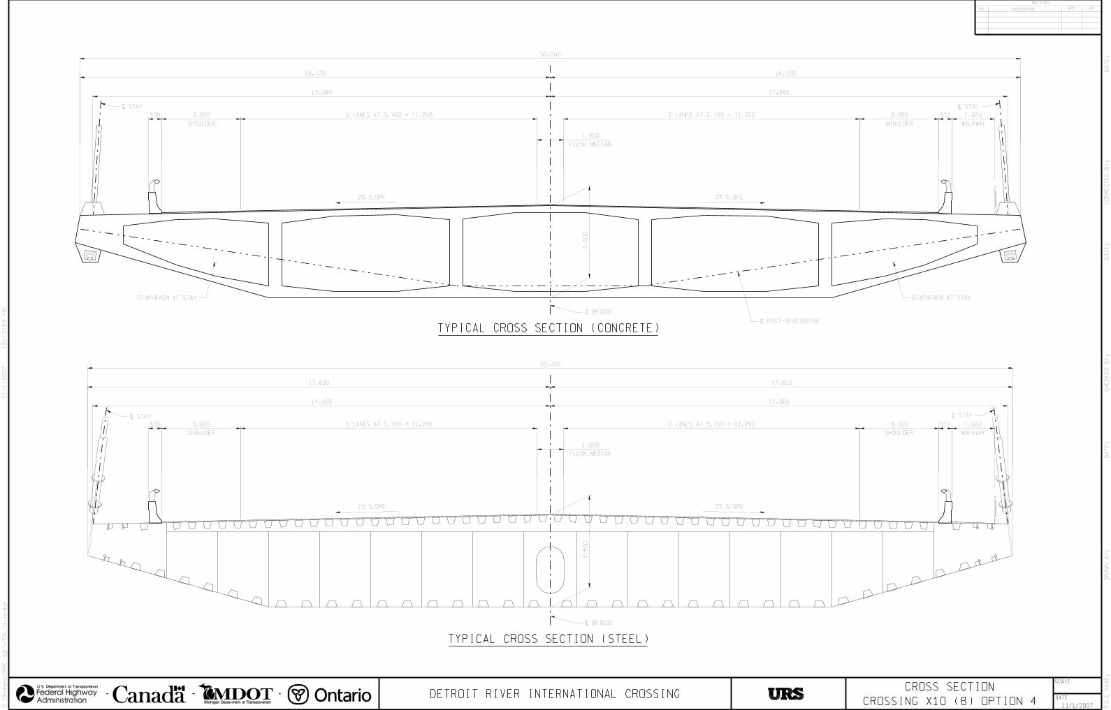
CROSS SECTION
CROSSING X10 (B) OPTION 4
FIL
E N
AM
E:
U.S. Department of Transportation
Administration
Federal Highway
Michigan Department of Transportation
E:\
Brid
ges\D
RIC
\dg
n\x
10
b_
1a_
xs.d
gn
DETROIT RIVER INTERNATIONAL CROSSING
SCALE
11/1/2007
DATE
CH
EC
KE
D B
Y:
DA
TE
:
CO
RR
EC
TE
D B
Y: D
AT
E:
DR
AW
N B
Y: D
AT
E:
REVISIONS
NO. DESCRIPTION DATE BY
12
:1
3:5
9 P
M11/1/2007
\ BRIDGE
\ STAY
\ BRIDGE
\ POST-TENSIONING
DIAPHRAGM AT STAYDIAPHRAGM AT STAY
510510
\ STAY
17.365
36.200
18.100 18.100
3 LANES AT 3.750 = 11.250 3 LANES AT 3.750 = 11.250 3.000
SHOULDER
1.600
WALKWAY
3.000
SHOULDER
3.5
00
2% SLOPE 2% SLOPE
TYPICAL CROSS SECTION (CONCRETE)
35.200
17.600 17.600
3 LANES AT 3.750 = 11.2503.000
SHOULDER
510 3 LANES AT 3.750 = 11.250
3.5
00
2% SLOPE 2% SLOPE
510
17.365
3.000
SHOULDER
1.600
WALKWAY
TYPICAL CROSS SECTION (STEEL)
17.365
17.365
\ STAY \ STAY
1.000
FLUSH MEDIAN
1.000
FLUSH MEDIAN

TOWER ELEVATIONS
CROSSING X10(B) OPTION 4
NOTES:
1. ALL DIMENSIONS ARE IN METERS.
FIL
E N
AM
E:
U.S. Department of Transportation
Administration
Federal Highway
Michigan Department of Transportation
E:\
Brid
ges\D
RIC
\dg
n\x
10
b_
1a_
tow
er.d
gn
DETROIT RIVER INTERNATIONAL CROSSING
SCALE
11/1/2007
DATE
CH
EC
KE
D B
Y:
DA
TE
:
CO
RR
EC
TE
D B
Y: D
AT
E:
DR
AW
N B
Y: D
AT
E:
REVISIONS
NO. DESCRIPTION DATE BY
12
:1
3:5
6 P
M11/1/2007
A - SHAPE PYLON ELEVATION Y - SHAPE PYLON ELEVATION
5.000
(TYP)
VARIES
6.000 TO 7.000
\ PYLON
6.000
\ PYLON
APPROX. EXIST.
GROUND LINE
E
E
B B
AA
5.000
(TYP)
E
E
C C
AA
21
0.0
00
13
9.0
00
39
.50
0
39
.50
02
10
.00
0
APPROX. EXIST.
GROUND LINE
D
D
D
D
2.5000 ! DRILLED
SHAFTS (TYP)
2.5000 ! DRILLED
SHAFTS (TYP)
F
F
6.0
00
61.000 57.000
6.0
00
SECTION A-A
SECTION B-B
SECTION C-C
.750
.750
.750
\ PYLON
\ PYLON
\ PYLONVA
RIE
S
7.0
00 T
O 1
1.0
00
VARIES
6.000 TO 7.000
VARIES
7.000 TO 8.100
VARIES
7.000 TO 7.600
VARIES
6.000 TO 13.100
67
.50
0
67
.50
0
26 S
PA
CE
S @
2.5
00
26 S
PA
CE
S @
2.5
00
2.5
00
2.5
00
\ PYLON
MAIN SPANAPPROACH SPAN
(STEEL ANCHORAGE FRAME NOT SHOWN)
(STEEL ANCHORAGE FRAME NOT SHOWN)
SECTION D-D
.750
SECTION E-E (STEEL ANCHORAGE FRAME NOT SHOWN)
5.000
6.0
00
6.000
SECTION F-F
7.5
00
7.5
00
21
.00
0
8.0
00
7.500 7.500
21.000
3.0
00
3.0
00 3.000 3.000

PLAN
263.100
ELEVATION
PLAN
GENERAL PLAN & ELEVATION
CROSSING X10 (B) OPTION 7
NOTE:
GRADE 5.00%
US HL
\ NA
VIG
AT
ION
AL
CH
AN
NE
L
DE
TR
OIT
RIV
ER
HWL EL. 175.439
\ US TOWER
L NAVIGATIONAL
CHANNEL
C \ CANADIAN TOWER
(TYP)
12.000
* MEASURED PERPENDICULAR TO
L NAVIGATION CHANNELC
\ PIER\ PIER
46.3
30
40.5
40
\ PIER
855.000
\ PIER
CA
BL
E P
.I.
\ T
OW
ER
\ T
OW
ER
4 SPACES = 253.000 4 SPACES = 244.000
L TOWERC
10
0.0
00
GROUND LINE
\ PIER \ PIER
ANCHORAGE
CA
BL
E P
.I.
\ MAIN CABLE
EL. 234.7
\ US TOWER
UNITED STATESCANADA
ANCHORAGE
\ CANADIAN TOWER
\ PIER \ PIER\ PIER \ PIER \ PIER \ PIER
ANCHORAGE
\ PIER 68.87̂
ST
A.
11
+2
44
.50
0
ST
A.
12
+0
99
.50
0
ST
A.
10
+9
91
.50
0
EL
. 2
00
.0
ST
A.
12
+3
43
.50
0
EL
. 2
00
.0
MAIN CABLE P.I. EL. 317.0
ANCHORAGE
STA.11+181.250
\ PIER
STA.11+118.000
\ PIER
STA.11+054.750
STA.11+244.500 STA.12+160.500
STA.12+241.500 STA.12+432.275
STA. 12+099.500
\ PIER
STA.12+302.500
11+000 11+500 12+000
365.000
363.000
GRADE 5.00%
350.000
US RIVER BANK
30.000
*
*
348.000 *
CANADIAN RIVER BANK
500 10050 150 200
SCALE IN METERS
1:2500
UNITS SHOWN IN METERS.
\ PIERSTA. 10+860.000
\ PIERSTA. 10+920.000
FIL
E N
AM
E:
U.S. Department of Transportation
Administration
Federal Highway
Michigan Department of Transportation
P:\
646294_D
RIC
_S
TU
DY
\CA
DD
\Practi
cal
Alt
ernati
ves\C
onceptu
al
Engin
eerin
g\C
E7-G
PE
.dgn
DETROIT RIVER INTERNATIONAL CROSSING
SCALE
1:2500
11/6/2007
DATE
CH
EC
KE
D B
Y:
DA
TE
:
CO
RR
EC
TE
D B
Y: D
AT
E:
DR
AW
N B
Y: D
AT
E:
REVISIONS
NO. DESCRIPTION DATE BY
9:3
1:1
5 A
M11/6/2007

1:50
TYPICAL CROSS SECTION
TYPE II RIB PL
SHOULDER
3 LANES AT 3 750 = 11 2503 LANES AT 3 750 = 11 2503 000
SHOULDER
\ BRIDGE
2%
510
1 000
FLUSH MEDIAN
2 040 510
17 300
1 600
WALKWAY
17 300
34 600
5 650
1 8
89
1 0
20
25 055 5 650
2%
2 032 MIN
CLEAR
3 2
50
DECK PL
BULKHEAD PL
TYPE I RIB PL
EDGE PL
SIDE PL
BOTTOM PL
BOX GIRDER SECTIONS
CROSSING X10 (B) OPTION 7
FIL
E N
AM
E:
U.S. Department of Transportation
Administration
Federal Highway
Michigan Department of Transportation
P:\
64
62
94
_D
RIC
_S
TU
DY
\CA
DD
\Practi
cal
Alt
ern
ati
ves\C
on
cep
tual
En
gin
eerin
g\C
E7
-secti
on
.dg
n
DETROIT RIVER INTERNATIONAL CROSSING
SCALE
1:2500
11/1/2007
DATE
CH
EC
KE
D B
Y: D
AT
E:
CO
RR
EC
TE
D B
Y: D
AT
E:
DR
AW
N B
Y: D
AT
E:
REVISIONS
NO. DESCRIPTION DATE BY
2:3
1:4
7 P
M11/1/2007

ELEVATION
EL. 317.0 CABLE P.I.
EL. 315.0 TOP OF TOWER
EL. 222.5 P.G.L.
EL. 179.0
EL. 174.0
EL. 167.5
4 500 (TYP)
21 335 21 335
10 740
17 900
9 900 9 900
27 700
10 000
16 790 16 790
L BRIDGEC
6 500
6 750
3 5
00
3 500 5 370 5 370 3 500
\ TOWER
17 900
9 9
00
27 7
00
9 9
00
3 5
00
3 000
(TYP)
\ TOWER
8 0
00
6 100300
300 300
300
1 000
1 0
00
80
08
00
9 3
00
LO
WE
R S
TR
UT
6 2
00 U
PP
ER
ST
RU
T
7 8
00
MID
DL
E S
TR
UT
\ SYM ABOUT
STRUT AND
TOWR
500 750\ TOWER
4 500
50
0
VA
RIE
S
SO
UT
H F
AC
E
150
15
0
1 2
00
EAST FACE
\ TOWER AND
SYMMETRICAL
SYMMETRICAL ABOUT
\ BRIDGE
TOWER
CROSSING X10 (B) OPTION 7
C
A A
B B
C
SECTION A-A
SECTION C-C
SECTION B-B
GROUND LEVEL
NOTE:
UNITS SHOWN IN METERS.
FIL
E N
AM
E:
U.S. Department of Transportation
Administration
Federal Highway
Michigan Department of Transportation
P:\
64
62
94
_D
RIC
_S
TU
DY
\CA
DD
\Practi
cal
Alt
ern
ati
ves\C
on
cep
tual
En
gin
eerin
g\C
E7
-T
ow
er.d
gn
DETROIT RIVER INTERNATIONAL CROSSING
SCALE
1:2500
11/6/2007
DATE
CH
EC
KE
D B
Y:
DA
TE
:
CO
RR
EC
TE
D B
Y: D
AT
E:
DR
AW
N B
Y: D
AT
E:
REVISIONS
NO. DESCRIPTION DATE BY
7:4
5:1
0 A
M11/6/2007
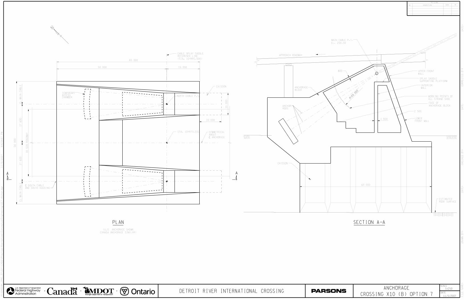
NORTH CABLE P.I.
STA. 10+973.331
SOUTH CABLE P.I.
ANCHORAGE ELEVATION
SECTION A-A
SECTION A-A
1:250
510
SCALE IN METERS
1:250
ANCHORAGE
CROSSING X10 (B) OPTION 7
65 000
CABLE SPLAY SADDLE
REFERENCE LINE
(STA. 10+991.500)
50 000
A
STA. 10+973.331
NORTH CABLE P.I.
15 000
SYMMETRICAL
ABOUT
\ ANCHORAGE
CL
MA
IN C
AB
LE
17
60
0
30 5
20 R
OA
DW
AY
17
60
0C
L M
AIN
CA
BL
E
56 0
00
PLAN
\ SOUTH CABLE
AND SOUTH HOUSING
A
ANCHOR
RODS
800
APPROACH ROADWAY
1 500
UPPER FRONT
WALL
WORKING POINTS OF
ALL STRAND SHOE
2 500
LOWER
FRONT WALL
SPLAY SADDLE
SUPPORTING PLATFORM
R=20
000
CAISSON
TEMPORARYACCESSCHAMBER
INTERIOR
WALL
FACE OF
ANCHORAGE BLOCK
ANCHORAGE
BLOCK
CAISSON
10 000
10
00
0
60 000
MAIN CABLE P.I.
EL. 200.00
(U.S. ANCHORAGE SHOWN
CANADA ANCHORAGE SIMILAR)
ESTIMATED
ROCK SURFACE
FIL
E N
AM
E:
U.S. Department of Transportation
Administration
Federal Highway
Michigan Department of Transportation
P:\
646294_D
RIC
_S
TU
DY
\CA
DD
\Practi
cal
Alt
ernati
ves\C
onceptu
al
Engin
eerin
g\C
E7-A
nchor.d
gn
DETROIT RIVER INTERNATIONAL CROSSING
SCALE
1:2500
11/5/2007
DATE
CH
EC
KE
D B
Y:
DA
TE
:
CO
RR
EC
TE
D B
Y: D
AT
E:
DR
AW
N B
Y: D
AT
E:
REVISIONS
NO. DESCRIPTION DATE BY
6:2
0:3
7 P
M11/5/2007
ANCHORAGE ELEVATION
SECTION A-A


1:50
TYPE II RIB PL
SHOULDER
3 LANES AT 3 750 = 11 2503 LANES AT 3 750 = 11 2503 000
SHOULDER
\ BRIDGE
2%
510
1 000
FLUSH MEDIAN
2 340 510
17 365
1 600
WALKWAY
740
35 200
6 070
2 0
80
22 800
2%
2 032 MIN
CLEAR
235
3 2
50
23517 365
6 070
TYPICAL CROSS SECTION (STEEL)
BOTTOM PL
SIDE PL
SIDE PL
BULKHEAD PL
DECK PL
BULKHEAD PL
TYPE I RIB PL
2% SLOPE 2% SLOPE
\ BRIDGE\ STAY @ DECK
\ STAY
\ STAY @ DECK
11 400 11 400
5 700 5 700
17 36517 365
300
225
225
2 2
50
6 7006 700
510 3 000
SHOULDER
3 LANES AT 3 750 = 11 250
36 200
3 LANES AT 3 750 = 11 250
1 000
FLUSH MEDIAN
510
SHOULDER
3 000 1 600
WALKWAY
\ STAY
TYPICAL CROSS SECTION (CONCRETE)
3 2
50
BOX GIRDER SECTIONS
CROSSING X11(C) OPTION 9 FIL
E N
AM
E:
U.S. Department of Transportation
Administration
Federal Highway
Michigan Department of Transportation
P:\
64
62
94
_D
RIC
_S
TU
DY
\CA
DD
\Practi
cal
Alt
ern
ati
ves\C
on
cep
tual
En
gin
eerin
g\C
E9
-secti
on
.dg
n
DETROIT RIVER INTERNATIONAL CROSSING
SCALE
1:2500
11/1/2007
DATE
CH
EC
KE
D B
Y: D
AT
E:
CO
RR
EC
TE
D B
Y: D
AT
E:
DR
AW
N B
Y: D
AT
E:
REVISIONS
NO. DESCRIPTION DATE BY
2:3
3:3
7 P
M11/1/2007

6.000
Y-SHAPE PYLON ELEVATION A-SHAPE PYLON ELEVATION
B B
AA
C C
44.0
00
AA
5.000
VA
RIE
S
(9.0
00-6
.900)
VARIES
(11.800-5.400)
(7.0
00-6
.000)
VA
RIE
S
44.0
00
17
1.0
00
5.000
2.0
00
2.0
00
SECTION A-A
\ PYLON
SECTION C-C
SECTION B-B
\ PYLON
VA
RIE
S
(6.9
00-6
.000)
6.000
D
D
GROUND LEVELGROUND LEVEL
SECTION D-D
10
8.5
00
62.5
00
B B
20
SP
A @
2.0
00
0.675
0.675
0.675
6.000
17
1.0
00
1.500 2.500
D
D
MAIN SPAN APPROACH SPAN
20 S
PA
@ 2
.000
42.0
00
42.0
00
\ PYLON
NOTE:
UNITS SHOWN IN METERS.
NOTE:
UNITS SHOWN IN METERS.
NOTE:
UNITS SHOWN IN METERS.
CH
EC
KE
D B
Y:
D
AT
E:
1:2500
11/5/2007
5.000
62 000
9 450
58 000
9 450
SECTION E-E
E E
3.0
00
6.0
00
17.900
3.500 5.370 5.370
27.7
00
3.5
00
3.5
00
9.9
00
9.9
00
3.000
(TYP)
8.0
00
(TYP)
3.500
\ TOWER
\ TOWER
SYMMETRICAL ABOUT
\ BRIDGE
PYLON
CROSSING X11(C) OPTION 9 FIL
E N
AM
E:
U.S. Department of Transportation
Administration
Federal Highway
Michigan Department of Transportation
P:\
64
62
94
_D
RIC
_S
TU
DY
\CA
DD
\Practi
cal
Alt
ern
ati
ves\C
on
cep
tual
En
gin
eerin
g\C
E9
-p
ylo
n.d
gn
DETROIT RIVER INTERNATIONAL CROSSING
SCALE
1:2500
11/5/2007
DATE
CH
EC
KE
D B
Y:
DA
TE
:
CO
RR
EC
TE
D B
Y: D
AT
E:
DR
AW
N B
Y: D
AT
E:
REVISIONS
NO. DESCRIPTION DATE BY
5:4
0:2
3 P
M11/5/2007

PLAN
ELEVATION
GENERAL PLAN & ELEVATION
CROSSING X11(C) OPTION 10
UNITED STATES CANADA
\ NAVIGATION CHANNEL
1:2500
US H
L
CA
NA
DIA
N H
L
1. ALL DIMENSIONS ARE IN METERS.
NOTES:
500 10050 150 200
SCALE IN METERS
1:2500
11+500 12+000 12+500
PC
= S
TA
. 12
+8
50
.84
7
PT
= S
TA
. 11
+3
76
.46
0
\ PIER
STA.11+423.000
\ PIER
STA.11+618.000
\ PIER
STA.11+488.000
\ PIER
STA.11+683.000
\ PIER
STA.12+638.000
\ PIER
STA.12+833.000
\ PIER
STA.12+573.000
\ PIER
STA.12+768.000
\ US TOWER
STA.11+748.000
\ US ANCHORAGE
STA.11+558.000
\ CANADIAN TOWER
STA. 12+508.000
\ CANADIAN ANCHORAGE
STA.12+698.000
61.16%%d
DE
TR
OIT
RIV
ER
\ PIER
STA.11+553.000
\ PIER
STA.12+703.000
\ CANADIAN TOWER\ UNITED STATES TOWER
\ NAVIGATION CHANNEL
\ PIER (TYP)
GRADE 5.00% GRADE 5.00%
30.000
CANADIAN
ANCHORAGE
UNITED STATES
ANCHORAGE
14.000 14.00061 SPACES @ 12.000 = 732.000
47.500 40.540
6.000
(TYP)
9.000
(TYP)
190.000
760.000
ORTHOTROPIC STEEL BOX GIRDER DECK
190.000
255.00 293.00
HWL
EL. 175.439
* MEASURED PERPENDICULAR TO \ NAVIGATION CHANNEL
* *
FIL
E N
AM
E:
U.S. Department of Transportation
Administration
Federal Highway
Michigan Department of Transportation
E:\
Brid
ges\D
RIC
\dg
n\x
11
c_
2a.d
gn
DETROIT RIVER INTERNATIONAL CROSSING
SCALE
11/1/2007
DATE
CH
EC
KE
D B
Y:
DA
TE
:
CO
RR
EC
TE
D B
Y: D
AT
E:
DR
AW
N B
Y: D
AT
E:
REVISIONS
NO. DESCRIPTION DATE BY
3:36:40 P
M11/1/2007

CROSS SECTION
CROSSING X11 (C) OPTION 10
FIL
E N
AM
E:
U.S. Department of Transportation
Administration
Federal Highway
Michigan Department of Transportation
E:\
Brid
ges\D
RIC
\dg
n\x
11
c_
2a_
xs.d
gn
DETROIT RIVER INTERNATIONAL CROSSING
SCALE
11/1/2007
DATE
CH
EC
KE
D B
Y:
DA
TE
:
CO
RR
EC
TE
D B
Y: D
AT
E:
DR
AW
N B
Y: D
AT
E:
REVISIONS
NO. DESCRIPTION DATE BY
2:40:09 P
M11/1/2007
\ BRIDGE
3 LANES AT 3.750 = 11.2503.000
SHOULDER
510 3 LANES AT 3.750 = 11.250
3.5
00
2% SLOPE 2% SLOPE
510
17.300
3.000
SHOULDER
1.600
WALKWAY
17.300
1.000
FLUSH MEDIAN
36.300
2.040
TYPICAL CROSS SECTION
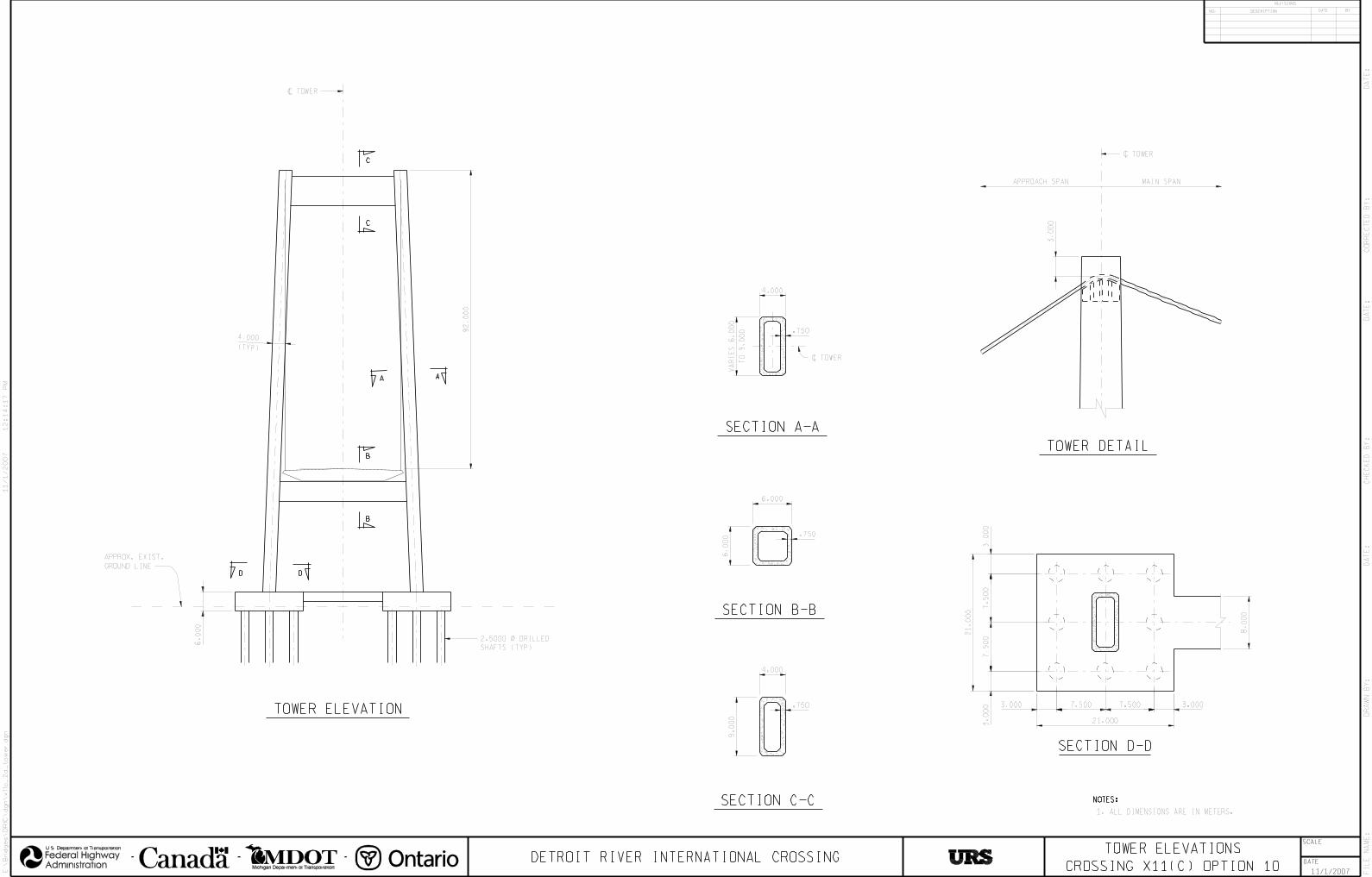
NOTES:
1. ALL DIMENSIONS ARE IN METERS.
TOWER ELEVATIONS
CROSSING X11(C) OPTION 10
FIL
E N
AM
E:
U.S. Department of Transportation
Administration
Federal Highway
Michigan Department of Transportation
E:\
Brid
ges\D
RIC
\dgn\x
11c_2a_to
wer.d
gn
DETROIT RIVER INTERNATIONAL CROSSING
SCALE
11/1/2007
DATE
CH
EC
KE
D B
Y:
DA
TE
:
CO
RR
EC
TE
D B
Y: D
AT
E:
DR
AW
N B
Y: D
AT
E:
REVISIONS
NO. DESCRIPTION DATE BY
12:14:17 P
M11/1/2007
\ TOWER
4.000
(TYP)
TOWER ELEVATION
A A
APPROX. EXIST.
GROUND LINE
B
B
C
C
D
2.5000 ! DRILLED
SHAFTS (TYP)
D
6.0
00
92
.00
0
SECTION A-A
.750
\ TOWER
APPROACH SPAN MAIN SPAN
\ TOWER
TOWER DETAIL
3.0
00
SECTION B-B
.750
SECTION C-C
.750
4.000
6.0
00
6.000
4.000
9.0
00
VA
RIE
S 6
.000
TO
9.0
00
SECTION D-D
21
.00
0
7.5
00
7.5
00
7.500 7.500
21.000
8.0
00
3.0
00
3.0
00 3.0003.000
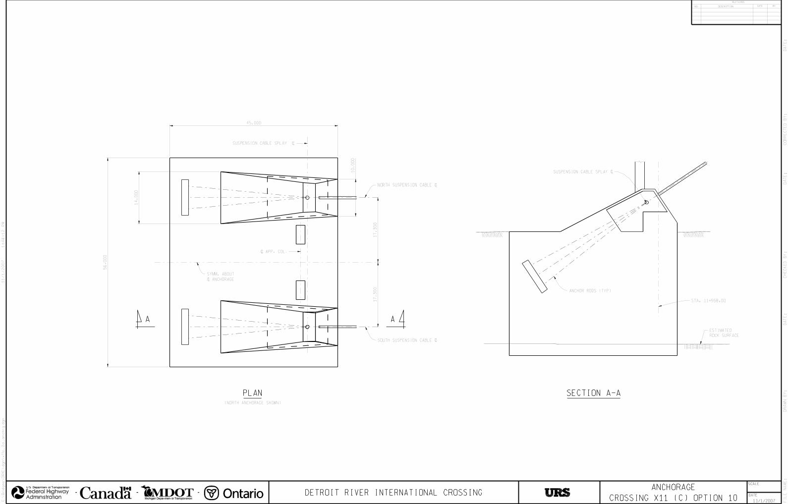
ANCHORAGE
CROSSING X11 (C) OPTION 10 FIL
E N
AM
E:
U.S. Department of Transportation
Administration
Federal Highway
Michigan Department of Transportation
E:\
Brid
ges\D
RIC
\dg
n\x
11
c_
2a_
an
ch
rg
.dg
n
DETROIT RIVER INTERNATIONAL CROSSING
SCALE
11/1/2007
DATE
CH
EC
KE
D B
Y:
DA
TE
:
CO
RR
EC
TE
D B
Y: D
AT
E:
DR
AW
N B
Y: D
AT
E:
REVISIONS
NO. DESCRIPTION DATE BY
1:4
8:1
2 P
M11/1/2007
45.000
56
.00
0
17
.30
01
7.3
00
14
.00
0
ESTIMATED
ROCK SURFACE
SUSPENSION CABLE SPLAY \
10
.00
0
NORTH SUSPENSION CABLE \
SOUTH SUSPENSION CABLE \
\ APP. COL.
SYMM. ABOUT
\ ANCHORAGE
STA. 11+558.00
ANCHOR RODS (TYP)
SUSPENSION CABLE SPLAY \
A
A
PLAN SECTION A-A
(NORTH ANCHORAGE SHOWN)

Detroit River International Crossing Bridge Conceptual Engineering Report
February 2008
Conceptual Engineering Report_Final_080211.doc
APPENDIX B – Construction Schedules
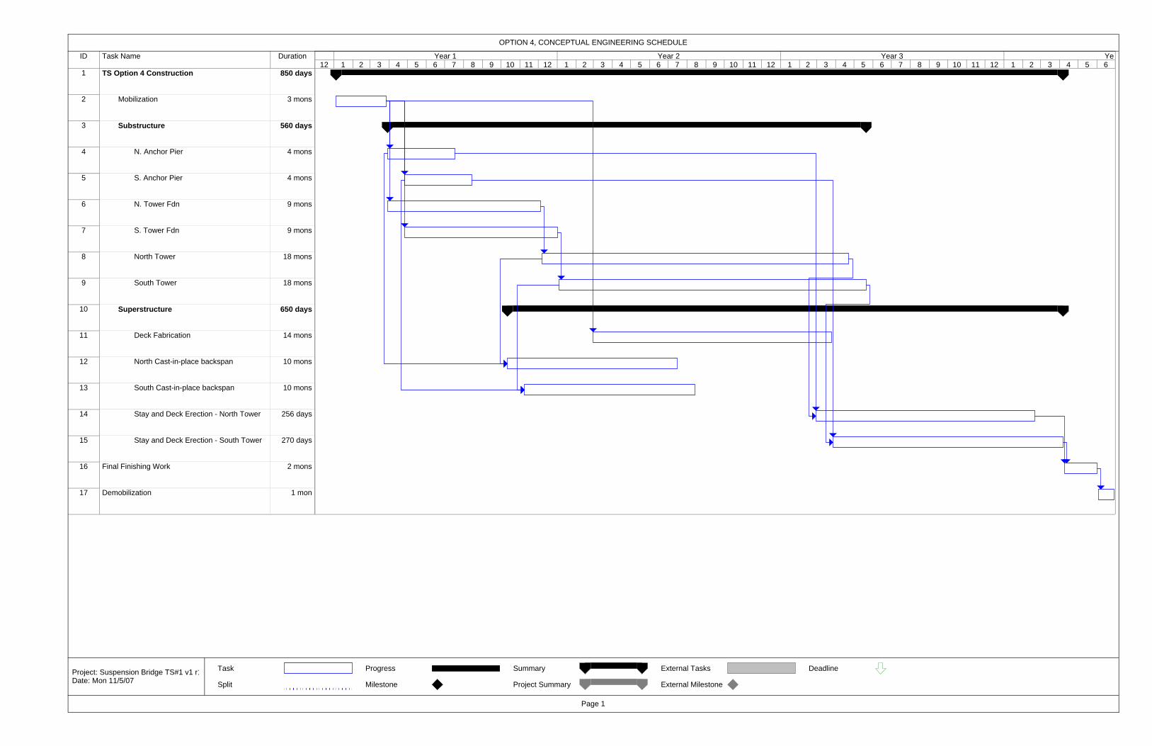
ID Task Name Duration
1 TS Option 4 Construction 850 days
2 Mobilization 3 mons
3 Substructure 560 days
4 N. Anchor Pier 4 mons
5 S. Anchor Pier 4 mons
6 N. Tower Fdn 9 mons
7 S. Tower Fdn 9 mons
8 North Tower 18 mons
9 South Tower 18 mons
10 Superstructure 650 days
11 Deck Fabrication 14 mons
12 North Cast-in-place backspan 10 mons
13 South Cast-in-place backspan 10 mons
14 Stay and Deck Erection - North Tower 256 days
15 Stay and Deck Erection - South Tower 270 days
16 Final Finishing Work 2 mons
17 Demobilization 1 mon
12 1 2 3 4 5 6 7 8 9 10 11 12 1 2 3 4 5 6 7 8 9 10 11 12 1 2 3 4 5 6 7 8 9 10 11 12 1 2 3 4 5 6Year 1 Year 2 Year 3 Ye
Task
Split
Progress
Milestone
Summary
Project Summary
External Tasks
External Milestone
Deadline
OPTION 4, CONCEPTUAL ENGINEERING SCHEDULE
Page 1
Project: Suspension Bridge TS#1 v1 r1Date: Mon 11/5/07

ID Task Name Duration
1 CE Option 7 Susp. Bridge Construction 980 days
2 Mobilization 3 mons
3 Substructure 520 days
4 N. Anchorage 18 mons
5 S. Anchorage 18 mons
6 N. Tower Fdn 10 mons
7 S. Tower Fdn 10 mons
8 North Tower 13 mons
9 South Tower 13 mons
10 Superstructure 540 days
11 Main Cable - In Place 380 days
12 Equipment Erection, Catwalk 3 mons
13 Cable Spinning & compacting 5 mons
14 Bands & Suspenders 3 mons
15 Cable Wrapping 3 mons
16 Remove Catwalk 1 mon
17 Deck 460 days
18 Fabrication 14 mons
19 Deck Erection 4 mons
20 Finishing Work 2 mons
21 Demobilization 1 mon
12 1 2 3 4 5 6 7 8 9 10 11 12 1 2 3 4 5 6 7 8 9 10 11 12 1 2 3 4 5 6 7 8 9 10 11 12 1 2 3 4 5 6 7 8 9 10 11Year 1 Year 2 Year 3 Year 4
Task
Split
Progress
Milestone
Summary
Project Summary
External Tasks
External Milestone
Deadline
OPTION 7, CONCEPTUAL ENGINEERING SCHEDULE
Page 1
Project: DRIC Susp. Bridge Const.Date: Mon 11/5/07

ID Task Name Duration
1 TS Option 9 Cable-Stayed Construction 810 days
2 Mobilization 3 mons
3 Substructure 560 days
4 N. Anchor Pier 4 mons
5 S. Anchor Pier 4 mons
6 N. Tower Fdn 9 mons
7 S. Tower Fdn 9 mons
8 North Tower 18 mons
9 South Tower 18 mons
10 Superstructure 610 days
11 Deck Fabrication 14 mons
12 North Cast-in-place backspan 9 mons
13 South Cast-in-place backspan 10 mons
14 Stay and Deck Erection - North Tower 220 days
15 Stay and Deck Erection - South Tower 230 days
16 Final Finishing Work 3 mons
17 Demobilization 1 mon
12 1 2 3 4 5 6 7 8 9 10 11 12 1 2 3 4 5 6 7 8 9 10 11 12 1 2 3 4 5 6 7 8 9 10 11 12 1 2 3 4 5 6Year 1 Year 2 Year 3 Ye
Task
Split
Progress
Milestone
Summary
Project Summary
External Tasks
External Milestone
Deadline
OPTION 9, CONCEPTUAL ENGINEERING SCHEDULE
Page 1
Project: Suspension Bridge TS#1 v1 r1Date: Mon 11/5/07

ID Task Name
1 CE Option 10 Susp. Bridge Construction
2 Mobilization
3 Substructure
4 N. Anchorage
5 S. Anchorage
6 N. Tower Fdn
7 S. Tower Fdn
8 North Tower
9 South Tower
10 Superstructure
11 Main Cable - In Place
12 Equipment Erection, Catwalk
13 Cable Spinning & compacting
14 Bands & Suspenders
15 Cable Wrapping
16 Remove Catwalk
17 Deck
18 Fabrication
19 Deck Erection
20 Finishing Work
21 Demobilization
12 1 2 3 4 5 6 7 8 9 10 11 12 1 2 3 4 5 6 7 8 9 10 11 12 1 2 3 4 5 6 7 8 9 10 11 12 1 2 3 4 5 6 7 8 9Year 1 Year 2 Year 3 Year 4
Task
Split
Progress
Milestone
Summary
Project Summary
External Tasks
External Milestone
Deadline
OPTION 10, CONCEPTUAL ENGINEERING SCHEDULE
Page 1
Project: DRIC Susp. Bridge Const.Date: Mon 11/5/07

Detroit River International Crossing Bridge Conceptual Engineering Report
February 2008
Conceptual Engineering Report_Final_080211.doc
APPENDIX C – Detailed Cost Estimates
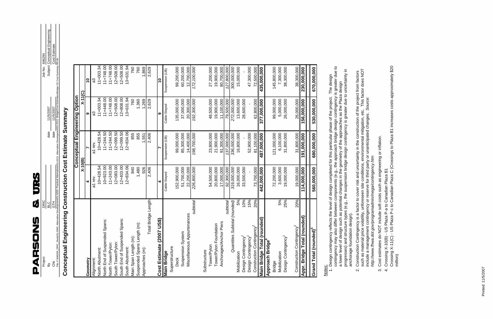
parsons
&P
roje
ctD
RIC
Job
No.
64
6294
By
BLC
date
11/5
/200
7S
ubje
ctC
once
ptua
l Eng
inee
ring
Chk
GTH
date
11/5
/200
7C
ost E
stim
ate
File
: F:\6
4629
4_D
RIC
_Stu
dy\0
1.00
00 A
ltern
ativ
e D
evel
opm
ent\0
1.02
00 P
ract
ical
Alte
rnat
ives
\01.
0210
Alte
rnat
ive
Dev
elop
men
t\01.
0211
Brid
ge\C
ost E
stim
ates
\Brid
ge C
E C
ost S
umm
ary
R6.
xls
Con
cept
ual E
ngin
eerin
g C
onst
ruct
ion
Cos
t Est
imat
e Su
mm
ary
47
910
Alig
nmen
t:a1
rev.
a1 re
v.a3
a3N
orth
Abu
tmen
t:10
+428
.54
10+4
28.5
411
+003
.34
11+0
03.3
4N
orth
End
of S
uspe
nded
Spa
ns:
10+9
23.0
011
+244
.50
11+4
48.0
011
+748
.00
Nor
th T
ower
/Pyl
on:
11+2
43.0
011
+244
.50
11+7
48.0
011
+748
.00
Sou
th T
ower
/Pyl
on:
12+0
83.0
012
+099
.50
12+5
08.0
012
+508
.00
Sou
th E
nd o
f Sus
pend
ed S
pans
:12
+403
.00
12+0
99.5
012
+808
.00
12+5
08.0
0S
outh
Abu
tmen
t:12
+834
.06
12+8
34.0
613
+631
.94
13+6
31.9
4M
ain
Spa
n Le
ngth
(m):
840
855
760
760
S
uspe
nded
Spa
ns L
engt
h (m
):1,
480
85
5
1,
360
76
0
App
roac
hes
(m):
926
1,55
1
1,26
9
1,86
9
To
tal B
ridge
Len
gth
2,40
6
2,40
6
2,62
9
2,62
9
Cos
t Est
imat
e (2
007
US$
)4
79
10M
ain
Brid
geC
able
-Sta
yed
Sus
pens
ion
(UB
)C
able
-Sta
yed
Sus
pens
ion
(UB
)
Sup
erst
ruct
ure
Dec
k15
2,90
0,00
0
99,0
00,0
00
13
5,00
0,00
0
99,2
00,0
00
Sus
pens
ion
Sys
tem
51,7
00,0
00
85
,300
,000
37,0
00,0
00
60
,200
,000
M
isce
llane
ous
App
urte
nanc
es22
,200
,000
14,4
00,0
00
20
,300
,000
12,7
00,0
00
subt
otal
226,
800,
000
19
8,70
0,00
0
192,
300,
000
17
2,10
0,00
0
Sub
stru
ctur
eTo
wer
/Pyl
on54
,500
,000
23,8
00,0
00
48
,500
,000
27,2
00,0
00
Tow
er/P
ylon
Fou
ndat
ion
20,8
00,0
00
21
,900
,000
19,9
00,0
00
19
,900
,000
A
ncho
rage
s/A
ncho
r Pie
rs17
,000
,000
91,3
00,0
00
11
,100
,000
80,7
00,0
00
subt
otal
92,3
00,0
00
137,
000,
000
79
,500
,000
12
7,80
0,00
0
Q
uant
ities
Sub
tota
l (ro
unde
d)31
9,00
0,00
0
336,
000,
000
27
2,00
0,00
0
300,
000,
000
Mob
iliza
tion
5%16
,000
,000
16,8
00,0
00
13
,600
,000
15,0
00,0
00
Des
ign
Con
tinge
ncy1
10%
33,5
00,0
00
-
28,6
00,0
00
-
D
esig
n C
ontin
genc
y115
%-
52,9
00,0
00
-
47,3
00,0
00
Con
stru
ctio
n C
ontin
genc
y220
%73
,700
,000
81,1
00,0
00
62
,800
,000
72,5
00,0
00
Mai
n B
ridge
Tot
al (r
ound
ed)
442,
000,
000
487,
000,
000
377,
000,
000
435,
000,
000
A
ppro
ach
Brid
ge4
Brid
ge72
,200
,000
121,
000,
000
99
,000
,000
145,
800,
000
Mob
iliza
tion
5%3,
600,
000
6,10
0,00
0
5,
000,
000
7,30
0,00
0
D
esig
n C
ontin
genc
y125
%19
,000
,000
31,8
00,0
00
26
,000
,000
38,3
00,0
00
Con
stru
ctio
n C
ontin
genc
y220
%19
,000
,000
31,8
00,0
00
26
,000
,000
38,3
00,0
00
App
r. B
ridge
Tot
al (r
ound
ed)
114,
000,
000
191,
000,
000
156,
000,
000
230,
000,
000
Gra
nd T
otal
(rou
nded
)556
0,00
0,00
0
68
0,00
0,00
0
53
0,00
0,00
0
67
0,00
0,00
0
Not
es:
1. 2. 3. 4.
Geo
met
ry
Con
cept
ual E
ngin
eerin
g O
ptio
n
Des
ign
cont
inge
ncy
refle
cts
the
leve
l of d
esig
n co
mpl
eted
for t
his
parti
cula
r pha
se o
f the
pro
ject
. Th
e de
sign
co
ntin
genc
y m
ay a
lso
diffe
r bet
wee
n co
mpo
nent
s (e
.g.,
the
appr
oach
brid
ge d
esig
n co
ntin
genc
y is
gre
ater
due
to
a lo
wer
leve
l of d
esig
n su
ch a
s po
tent
ial c
hang
es in
the
geom
etry
of t
he a
ppro
ache
s as
the
Pla
za d
esig
n pr
ogre
sses
) and
stru
ctur
e ty
pes
(e.g
., th
e su
spen
sion
brid
ge d
esig
n co
ntin
genc
y is
gre
ater
due
to u
ncer
tain
ty in
an
chor
age
foun
datio
n de
sign
).
Con
stru
ctio
n C
ontin
genc
y is
a fa
ctor
to c
over
risk
and
unc
erta
inty
in th
e co
nstru
ctio
n of
the
proj
ect f
rom
fact
ors
such
as
mat
eria
l pric
e vo
latil
ity, u
nfor
esee
n si
te c
ondi
tions
, env
ironm
enta
l miti
gatio
n, e
tc.
This
fact
or d
oes
NO
T in
clud
e a
man
agem
ent c
ontin
genc
y or
rese
rve
for t
hird
par
ty o
r una
ntic
ipat
ed c
hang
es.
Sou
rce:
ht
tp://
ww
w.fh
wa.
dot.g
ov/p
rogr
amad
min
/meg
a/co
ntin
genc
y.ht
m
X-10
(B)
X-11
(C)
Cro
ssin
g X
-11(
C) -
US
Pla
za P
-c to
Can
adia
n P
laza
C (C
ross
ings
to P
laza
B1
incr
ease
s co
sts
appr
oxim
atel
y $2
0 m
illio
n)
Cos
t est
imat
es d
o N
OT
incl
ude
soft
cost
s su
ch a
s en
gine
erin
g or
infla
tion.
Cro
ssin
g X
-10(
B) -
US
Pla
za P
-a to
Can
adia
n P
laza
B1
Prin
ted:
11/
5/20
07

Cal
cula
tion:
Una
ssig
ned
Pro
ject
DR
ICJo
b no
. by
date
5-N
ov-0
7S
ubje
ctC
once
ptua
l Eng
inee
ring
Cos
t Est
imat
ech
kda
teFi
le: F
:\646
294_
DR
IC_S
tudy
\01.
0000
Alte
rnat
ive
Dev
elop
men
t\01.
0200
Pra
ctic
al A
ltern
ativ
es\0
1.02
10 A
ltern
ativ
e D
evel
opm
ent\0
1.02
11 B
ridge
\Cos
t Est
imat
es\D
RIC
CE
Opt
ion
4 C
BLS
Est
imat
e R
6.xl
s
OPT
ION
:C
E O
ptio
n 4
CR
OSS
ING
: X-1
0(B
)G
eom
etry
Nor
th A
butm
ent:
STA
10+4
28.5
4M
ain
Spa
n Le
ngth
840
met
ers
Nor
th E
nd o
f Sus
pend
ed S
pans
:S
TA10
+923
.00
Sus
pend
ed S
pan
Leng
th14
80m
eter
sN
orth
Pyl
on:
STA
11+2
43.0
0U
S A
ppro
ach
Spa
n49
4m
eter
sS
outh
Pyl
on:
STA
12+0
83.0
0C
AN
App
roac
h S
pan
431
met
ers
Sou
th E
nd o
f Sus
pend
ed S
pans
:S
TA12
+403
.00
Orth
otro
pic
Dec
k Le
ngth
820
met
ers
Sou
th A
butm
ent:
STA
12+8
34.0
6C
oncr
ete
Dec
k Le
ngth
660
met
ers
Leng
th o
f Sus
pend
ed S
pans
1480
met
ers
Cab
le-to
-Cab
le W
idth
34.7
3m
eter
sIn
verte
d Y
Pyl
onLe
ngth
of A
ppro
ache
s92
6m
eter
sC
urb-
to-C
urb
Wid
th31
.52
met
ers
Item
Uni
t QTY
QTY
Mul
t.Q
TY T
otal
Uni
t Cos
tTo
tal
Tota
lSu
pers
truc
ture
Dec
k Orth
otro
pic
Box
Gird
er43
8.2
kg/m
228
,479
m2
12,4
79,7
15
kg
9.00
$
US
D/k
g11
2,30
0,00
0$
Con
cret
e B
ox G
irder
23.5
m3 /m
660
m15
,534
m3
2,00
0.00
$
U
SD
/m3
31,1
00,0
00$
B
ox G
irder
Rei
nfor
cing
130.
5
kg
/m3
15,5
34
m
32,
027,
498
kg2.
65$
U
SD
/kg
5,40
0,00
0$
Box
Gird
er P
rest
ress
ing
29.5
kg/m
315
,534
m3
458,
118
kg
9.00
$
US
D/k
g4,
100,
000
$
D
eck
Sub
tota
l15
2,90
0,00
0$
Stay
Sys
tem
Sta
y C
able
s1,
661,
054
kg
/pla
ne2
pl
ane
3,32
2,10
7
kg
13.2
0$
US
D/k
g43
,900
,000
$
Dec
k A
ncho
rage
s1,
178
kg/s
tay
216
stay
s25
4,54
5
kg11
.00
$
U
SD
/kg
2,80
0,00
0$
Dam
ping
Dev
ices
1
ea
/sta
y21
6
st
ays
216
ea23
,148
.15
$
U
SD
/ea
5,00
0,00
0$
Sta
y S
yste
m S
ubto
tal
51,7
00,0
00$
M
isc.
App
urte
nanc
esO
verla
y, B
arrie
rs, E
lect
.51
,400
m
2 /br
1
br51
,400
m2
161.
40$
U
SD
/m2
8,30
0,00
0$
Ligh
ting
, Dra
inag
e, e
tc.
51,4
00
m2 /b
r1
br
51,4
00
m
253
.80
$
U
SD
/m2
2,80
0,00
0$
Mis
cella
neou
s Ite
ms
51,4
00
m2 /b
r1
br
51,4
00
m
221
5.20
$
US
D/m
211
,100
,000
$
Mis
c. A
ppur
tena
nces
Sub
tota
l22
,200
,000
$
Supe
rstr
uctu
re S
ubto
tal
226,
800,
000
$
Su
bstr
uctu
rePy
lons Con
cret
e34
.8
m
3 /m49
9
m
for 2
17,3
42
m
32,
200.
00$
US
D/m
338
,200
,000
$
Rei
nfor
cing
Ste
el23
7.3
kg/m
317
,342
m3
4,11
5,43
0
kg
3.30
$
US
D/k
g13
,600
,000
$
Pre
stre
ssin
g S
teel
-
kg/m
317
,342
m3
-
kg
9.00
$
US
D/k
g-
$
Stru
ctur
al S
teel
1,38
9
kg
/sta
y21
6
st
ays
300,
000
kg
9.00
$
US
D/k
g2,
700,
000
$
P
ylon
s S
ubto
tal
54,5
00,0
00$
Py
lon
Foun
datio
nsFo
otin
g C
oncr
ete
7,45
2
m
3 /ea
2
ea14
,904
m3
588.
60$
U
SD
/m3
8,80
0,00
0$
Foot
ing
Rei
nfor
cing
90.0
kg/m
314
,904
m3
1,34
1,36
0
kg
2.65
$
US
D/k
g3,
600,
000
$
D
rille
d S
haft
Ste
el C
asin
g (1
6mm
)98
6.3
kg/m
896
m88
3,72
4
kg4.
40$
U
SD
/kg
3,90
0,00
0$
Dril
led
Sha
ft (1
6-2.
5m ø
/ py
lon)
32
shaf
ts28
m/s
haft
896
m5,
000.
00$
US
D/m
4,50
0,00
0$
Pyl
on F
ound
atio
ns S
ubto
tal
20,8
00,0
00$
A
ncho
r Pie
rsA
ncho
r Pie
r Con
cret
e88
9.8
m3 /e
a8
ea
7,11
8
m3
588.
60$
U
SD
/m3
4,20
0,00
0$
Anc
hor P
ier R
einf
orci
ng15
7.0
kg/m
37,
118
m
31,
117,
526
kg2.
65$
U
SD
/kg
3,00
0,00
0$
Foot
ing
Con
cret
e12
0.0
m3 /e
a8
ea
960
m3
588.
60$
U
SD
/m3
600,
000
$
Foot
ing
Rei
nfor
cing
90.0
kg/m
396
0
m
386
,400
kg2.
65$
U
SD
/kg
200,
000
$
Dril
led
Sha
ft S
teel
Cas
ing
(16m
m)
986.
3
kg
/m96
0
m
946,
886
kg
4.40
$
US
D/k
g4,
200,
000
$
D
rille
d S
haft
(4-2
.5m
ø /
pier
)32
sh
afts
30
m
/sha
ft96
0
m
5,00
0.00
$
U
SD
/m4,
800,
000
$
A
ncho
r Pie
rs S
ubto
tal
17,0
00,0
00$
Su
bstr
uctu
re S
ubto
tal
92,3
00,0
00$
Q
uant
ities
Sub
tota
l (ro
unde
d)31
9,00
0,00
0$
Mob
iliza
tion
5%16
,000
,000
$
Des
ign
Con
tinge
ncy
10%
33,5
00,0
00$
M
ain
Brid
ge T
otal
(rou
nded
)36
9,00
0,00
0$
App
roac
hes
Brid
ge29
,172
m
21
ea29
,172
m2
2,47
5.94
$
U
SD
/m2
72,2
00,0
00$
M
obili
zatio
n5%
3,60
0,00
0$
Des
ign
Con
tinge
ncy
25%
19,0
00,0
00$
A
ppro
ache
s To
tal (
roun
ded)
95,0
00,0
00$
B
ridge
Sub
tota
l46
4,00
0,00
0$
Con
stru
ctio
n C
ontin
genc
y20
%92
,800
,000
$
Brid
ge G
rand
Tot
al (r
ound
ed)
560,
000,
000
$
She
et: C
E O
ptio
n 4
Pag
e 1
of 1
Prin
ted:
11/
5/20
07 1
:25
PM
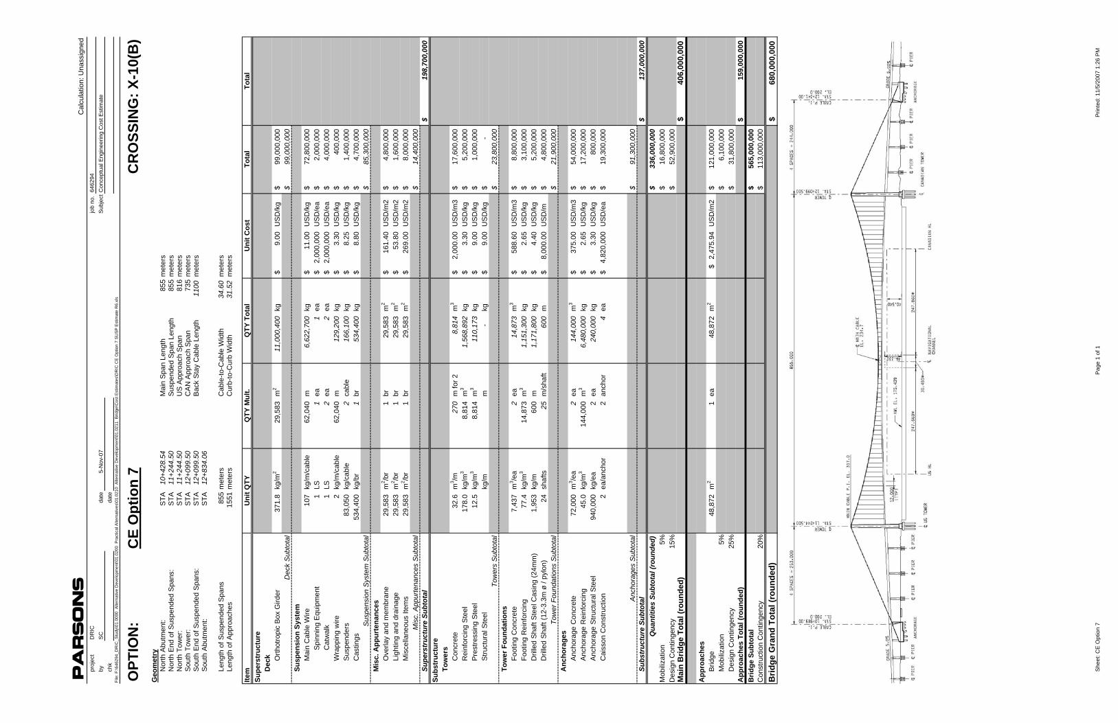
parsons
Cal
cula
tion:
Una
ssig
ned
proj
ect
DR
ICjo
b no
. 64
6294
byS
Cda
te5-
Nov
-07
Sub
ject
Con
cept
ual E
ngin
eerin
g C
ost E
stim
ate
chk
date
File
: F:\6
4629
4_D
RIC
_Stu
dy\0
1.00
00 A
ltern
ativ
e D
evel
opm
ent\0
1.02
00 P
ract
ical
Alte
rnat
ives
\01.
0210
Alte
rnat
ive
Dev
elop
men
t\01.
0211
Brid
ge\C
ost E
stim
ates
\DR
IC C
E O
ptio
n 7
SU
SP
Est
imat
e R
6.xl
s
OPT
ION
:C
E O
ptio
n 7
CR
OSS
ING
: X-1
0(B
)G
eom
etry
Nor
th A
butm
ent:
STA
10+4
28.5
4M
ain
Spa
n Le
ngth
855
met
ers
Nor
th E
nd o
f Sus
pend
ed S
pans
:S
TA11
+244
.50
Sus
pend
ed S
pan
Leng
th85
5m
eter
sN
orth
Tow
er:
ST A
11+2
44.5
0U
S A
ppro
ach
Spa
n81
6m
eter
sS
outh
Tow
er:
ST A
12+0
99.5
0C
AN
App
roac
h S
pan
735
met
ers
Sou
th E
nd o
f Sus
pend
ed S
pans
:S
T A12
+099
.50
Bac
k S
tay
Cab
le L
engt
h11
00m
eter
sS
outh
Abu
tmen
t:S
T A12
+834
.06
Leng
th o
f Sus
pend
ed S
pans
855
met
ers
Cab
le-to
-Cab
le W
idth
34.6
0m
eter
sLe
ngth
of A
ppro
ache
s15
51m
eter
sC
urb-
to-C
urb
Wid
th31
.52
met
ers
Item
Uni
t QTY
QTY
Mul
t.Q
TY T
otal
Uni
t Cos
tTo
tal
Tota
lSu
pers
truc
ture
Dec
k Orth
otro
pic
Box
Gird
er37
1.8
kg
/m2
29,5
83
m
211
,000
,400
kg9.
00$
US
D/k
g99
,000
,000
$
D
eck
Sub
tota
l99
,000
,000
$
Su
spen
sion
Sys
tem
Mai
n C
able
Wire
107
kg/m
/cab
le62
,040
m6,
622,
700
kg11
.00
$
U
SD
/kg
72,8
00,0
00$
Spi
nnin
g E
quip
men
t1
LS1
ea
1
ea2,
000,
000
$
US
D/e
a2,
000,
000
$
Cat
wal
k1
LS2
ea
2
ea2,
000,
000
$
US
D/e
a4,
000,
000
$
Wra
ppin
g w
ire2
kg/m
/cab
le62
,040
m12
9,20
0
kg3.
30$
US
D/k
g40
0,00
0$
Sus
pend
ers
83,0
50
kg/c
able
2
cabl
e16
6,10
0
kg8.
25$
US
D/k
g1,
400,
000
$
Cas
tings
534,
400
kg/b
r1
br
534,
400
kg
8.80
$
U
SD
/kg
4,70
0,00
0$
S
uspe
nsio
n S
yste
m S
ubto
tal
85,3
00,0
00$
Mis
c. A
ppur
tena
nces
Ove
rlay
and
mem
bran
e29
,583
m
2 /br
1
br29
,583
m2
161.
40$
U
SD
/m2
4,80
0,00
0$
Li
ghtin
g an
d dr
aina
ge29
,583
m
2 /br
1
br29
,583
m2
53.8
0$
US
D/m
21,
600,
000
$
Mis
cella
neou
s Ite
ms
29,5
83
m2 /b
r1
br
29,5
83
m
226
9.00
$
US
D/m
28,
000,
000
$
Mis
c. A
ppur
tena
nces
Sub
tota
l14
,400
,000
$
Su
pers
truc
ture
Sub
tota
l19
8,70
0,00
0$
Subs
truc
ture
Tow
ers
Con
cret
e32
.6
m
3 /m27
0
m
for 2
8,81
4
m3
2,00
0.00
$
U
SD
/m3
17,6
00,0
00$
Rei
nfor
cing
Ste
el17
8.0
kg
/m3
8,81
4
m3
1,56
8,89
2
kg
3.30
$
U
SD
/kg
5,20
0,00
0$
P
rest
ress
ing
Ste
el12
.5
kg
/m3
8,81
4
m3
110,
173
kg
9.00
$
U
SD
/kg
1,00
0,00
0$
S
truct
ural
Ste
elkg
/mm
-
kg
9.00
$
U
SD
/kg
-$
Tow
ers
Sub
tota
l23
,800
,000
$
To
wer
Fou
ndat
ions
Foot
ing
Con
cret
e7,
437
m
3 /ea
2
ea14
,873
m3
588.
60$
U
SD
/m3
8,80
0,00
0$
Fo
otin
g R
einf
orci
ng77
.4
kg
/m3
14,8
73
m
31,
151,
300
kg2.
65$
US
D/k
g3,
100,
000
$
Dril
led
Sha
ft S
teel
Cas
ing
(24m
m)
1,95
3
kg/m
600
m1,
171,
800
kg4.
40$
US
D/k
g5,
200,
000
$
Dril
led
Sha
ft (1
2-3.
3m ø
/ py
lon)
24
shaf
ts25
m/s
haft
600
m8,
000.
00$
US
D/m
4,80
0,00
0$
To
wer
Fou
ndat
ions
Sub
tota
l21
,900
,000
$
A
ncho
rage
sA
ncho
rage
Con
cret
e72
,000
m
3 /ea
2
ea14
4,00
0
m3
375.
00$
U
SD
/m3
54,0
00,0
00$
Anc
hora
ge R
einf
orci
ng45
.0
kg
/m3
144,
000
m3
6,48
0,00
0
kg
2.65
$
U
SD
/kg
17,2
00,0
00$
Anc
hora
ge S
truct
ural
Ste
el94
0,00
0
kg
/ea
2
ea24
0,00
0
kg3.
30$
US
D/k
g80
0,00
0$
Cai
sson
Con
stru
ctio
n2
ea/a
ncho
r2
an
chor
4
ea4,
820,
000
$
US
D/e
a19
,300
,000
$
Anc
hora
ges
Sub
tota
l91
,300
,000
$
Su
bstr
uctu
re S
ubto
tal
137,
000,
000
$
Q
uant
ities
Sub
tota
l (ro
unde
d)33
6,00
0,00
0$
M
obili
zatio
n5%
16,8
00,0
00$
Des
ign
Con
tinge
ncy
15%
52,9
00,0
00$
Mai
n B
ridge
Tot
al (r
ound
ed)
406,
000,
000
$
App
roac
hes
Brid
ge48
,872
m
21
ea
48,8
72
m
22,
475.
94$
U
SD
/m2
121,
000,
000
$
Mob
iliza
tion
5%6,
100,
000
$
Des
ign
Con
tinge
ncy
25%
31,8
00,0
00$
App
roac
hes
Tota
l (ro
unde
d)15
9,00
0,00
0$
B
ridge
Sub
tota
l56
5,00
0,00
0$
C
onst
ruct
ion
Con
tinge
ncy
20%
113,
000,
000
$
Brid
ge G
rand
Tot
al (r
ound
ed)
680,
000,
000
$
She
et: C
E O
ptio
n 7
Pag
e 1
of 1
Prin
ted:
11/
5/20
07 1
:26
PM

parsons
Cal
cula
tion:
Una
ssig
ned
Pro
ject
DR
ICJo
b no
. 64
6294
byG
THda
te5-
Nov
-07
Sub
ject
Con
cept
ual E
ngin
eerin
g C
ost E
stim
ate
chk
date
File
: F:\6
4629
4_D
RIC
_Stu
dy\0
1.00
00 A
ltern
ativ
e D
evel
opm
ent\0
1.02
00 P
ract
ical
Alte
rnat
ives
\01.
0210
Alte
rnat
ive
Dev
elop
men
t\01.
0211
Brid
ge\C
ost E
stim
ates
\DR
IC C
E O
ptio
n 9
CB
LS E
stim
ate
R6.
xls
OPT
ION
:C
E O
ptio
n 9
CR
OSS
ING
: X-1
1(C
)G
eom
etry
Nor
th A
butm
ent:
STA
11+0
03.3
4M
ain
Spa
n Le
ngth
760
met
ers
Nor
th E
nd o
f Sus
pend
ed S
pans
:S
TA11
+448
.00
Sus
pend
ed S
pan
Leng
th13
60m
eter
sN
orth
Pyl
on:
STA
11+7
48.0
0U
S A
ppro
ach
Spa
n44
5m
eter
sS
outh
Pyl
on:
STA
12+5
08.0
0C
AN
App
roac
h S
pan
824
met
ers
Sou
th E
nd o
f Sus
pend
ed S
pans
:S
TA12
+808
.00
Orth
otro
pic
Dec
k Le
ngth
660
met
ers
Sou
th A
butm
ent:
STA
13+6
31.9
4C
oncr
ete
Dec
k Le
ngth
700
met
ers
Leng
th o
f Sus
pend
ed S
pans
1360
met
ers
Cab
le-to
-Cab
le W
idth
34.7
3m
eter
sIn
verte
d Y
Pyl
onLe
ngth
of A
ppro
ache
s12
69m
eter
sC
urb-
to-C
urb
Wid
th31
.52
met
ers
Item
Uni
t QTY
QTY
Mul
t.Q
TY T
otal
Uni
t Cos
tTo
tal
Tota
lSu
pers
truc
ture
Dec
k Orth
otro
pic
Box
Gird
er43
9.4
kg/m
222
,922
m2
10,0
71,8
50
kg
9.00
$
US
D/k
g90
,600
,000
$
Con
cret
e B
ox G
irder
24.0
m3 /m
700
m16
,800
m3
2,00
0.00
$
U
SD
/m3
33,6
00,0
00$
B
ox G
irder
Rei
nfor
cing
130.
5
kg
/m3
16,8
00
m
32,
192,
400
kg2.
65$
U
SD
/kg
5,80
0,00
0$
Box
Gird
er P
rest
ress
ing
33.2
kg/m
316
,800
m3
558,
000
kg
9.00
$
US
D/k
g5,
000,
000
$
D
eck
Sub
tota
l13
5,00
0,00
0$
Stay
Sys
tem
Sta
y C
able
s1,
143,
087
kg
/pla
ne2
pl
ane
2,28
6,17
3
kg
13.2
0$
US
D/k
g30
,200
,000
$
Dec
k A
ncho
rage
s1,
517
kg/s
tay
168
stay
s25
4,84
2
kg11
.00
$
U
SD
/kg
2,80
0,00
0$
Dam
ping
Dev
ices
1
ea
/sta
y16
8
st
ays
168
ea23
,809
.52
$
U
SD
/ea
4,00
0,00
0$
Sta
y S
yste
m S
ubto
tal
37,0
00,0
00$
M
isc.
App
urte
nanc
esO
verla
y, B
arrie
rs, E
lect
.47
,233
m
2 /br
1
br47
,233
m2
161.
40$
U
SD
/m2
7,60
0,00
0$
Ligh
ting
, Dra
inag
e, e
tc.
47,2
33
m2 /b
r1
br
47,2
33
m
253
.80
$
U
SD
/m2
2,50
0,00
0$
Mis
cella
neou
s Ite
ms
47,2
33
m2 /b
r1
br
47,2
33
m
221
5.20
$
US
D/m
210
,200
,000
$
Mis
c. A
ppur
tena
nces
Sub
tota
l20
,300
,000
$
Supe
rstr
uctu
re S
ubto
tal
192,
300,
000
$
Su
bstr
uctu
rePy
lons Con
cret
e35
.6
m
3 /m43
0
m
for 2
15,3
00
m
32,
200.
00$
US
D/m
333
,700
,000
$
Rei
nfor
cing
Ste
el23
7.3
kg/m
315
,300
m3
3,63
1,00
0
kg
3.30
$
US
D/k
g12
,000
,000
$
Pre
stre
ssin
g S
teel
3.3
kg
/m3
15,3
00
m
349
,949
kg9.
00$
U
SD
/kg
400,
000
$
Stru
ctur
al S
teel
1,61
7
kg
/sta
y16
8
st
ays
271,
662
kg
9.00
$
US
D/k
g2,
400,
000
$
P
ylon
s S
ubto
tal
48,5
00,0
00$
Py
lon
Foun
datio
nsFo
otin
g C
oncr
ete
6,60
8
m
3 /ea
2
ea13
,215
m3
588.
60$
U
SD
/m3
7,80
0,00
0$
Foot
ing
Rei
nfor
cing
90.0
kg/m
313
,215
m3
1,18
9,35
0
kg
2.65
$
US
D/k
g3,
200,
000
$
D
rille
d S
haft
Ste
el C
asin
g (1
6mm
)1,
184
kg/m
672
m79
5,38
0
kg4.
40$
U
SD
/kg
3,50
0,00
0$
Dril
led
Sha
ft (1
2-3.
0m ø
/ py
lon)
24
shaf
ts28
m/s
haft
672
m8,
000.
00$
US
D/m
5,40
0,00
0$
Pyl
on F
ound
atio
ns S
ubto
tal
19,9
00,0
00$
A
ncho
r Pie
rsA
ncho
r Pie
r Con
cret
e30
0.0
m3 /e
a10
ea3,
000
m
358
8.60
$
US
D/m
31,
800,
000
$
A
ncho
r Pie
r Rei
nfor
cing
270.
0
kg
/m3
3,00
0
m3
810,
000
kg
2.65
$
US
D/k
g2,
100,
000
$
Fo
otin
g C
oncr
ete
180.
0
m
3 /ea
10
ea1,
800
m
358
8.60
$
US
D/m
31,
100,
000
$
Fo
otin
g R
einf
orci
ng11
7.6
kg/m
31,
800
m
321
1,70
0
kg2.
65$
U
SD
/kg
600,
000
$
Dril
led
Sha
ft S
teel
Cas
ing
(16m
m)
591.
8
kg
/m1,
200
m
710,
160
kg
4.40
$
US
D/k
g3,
100,
000
$
D
rille
d S
haft
(4-1
.5m
ø /
pier
)40
sh
afts
30
m
/sha
ft1,
200
m
2,00
0.00
$
U
SD
/m2,
400,
000
$
A
ncho
r Pie
rs S
ubto
tal
11,1
00,0
00$
Su
bstr
uctu
re S
ubto
tal
79,5
00,0
00$
Q
uant
ities
Sub
tota
l (ro
unde
d)27
2,00
0,00
0$
Mob
iliza
tion
5%13
,600
,000
$
Des
ign
Con
tinge
ncy
10%
28,6
00,0
00$
M
ain
Brid
ge T
otal
(rou
nded
)31
4,00
0,00
0$
App
roac
hes
Brid
ge39
,986
m
21
ea39
,986
m2
2,47
5.94
$
U
SD
/m2
99,0
00,0
00$
M
obili
zatio
n5%
5,00
0,00
0$
Des
ign
Con
tinge
ncy
25%
26,0
00,0
00$
A
ppro
ache
s To
tal (
roun
ded)
130,
000,
000
$
B
ridge
Sub
tota
l44
4,00
0,00
0$
Con
stru
ctio
n C
ontin
genc
y20
%88
,800
,000
$
Brid
ge G
rand
Tot
al (r
ound
ed)
530,
000,
000
$
She
et: C
E O
ptio
n 9
Pag
e 1
of 1
Prin
ted:
11/
5/20
07 1
:27
PM

Cal
cula
tion:
Una
ssig
ned
proj
ect
DR
ICjo
b no
. by
date
5-N
ov-0
7S
ubje
ctC
once
ptua
l Eng
inee
ring
Cos
t Est
imat
ech
kda
teFi
le: F
:\646
294_
DR
IC_S
tudy
\01.
0000
Alte
rnat
ive
Dev
elop
men
t\01.
0200
Pra
ctic
al A
ltern
ativ
es\0
1.02
10 A
ltern
ativ
e D
evel
opm
ent\0
1.02
11 B
ridge
\Cos
t Est
imat
es\D
RIC
CE
Opt
ion
10 S
US
P E
stim
ate
R6.
xls
OPT
ION
:C
E O
ptio
n 10
CR
OSS
ING
: X-1
1(C
)G
eom
etry
Nor
th A
butm
ent:
STA
11+0
03.3
1M
ain
Spa
n Le
ngth
760
met
ers
Nor
th E
nd o
f Sus
pend
ed S
pans
:S
TA11
+748
.00
Sus
pend
ed S
pan
Leng
th76
0m
eter
sN
orth
Tow
er:
ST A
11+7
48.0
0U
S A
ppro
ach
Spa
n74
5m
eter
sS
outh
Tow
er:
ST A
12+5
08.0
0C
AN
App
roac
h S
pan
1124
met
ers
Sou
th E
nd o
f Sus
pend
ed S
pans
:S
T A12
+508
.00
Bac
k S
tay
Cab
le L
engt
hN
/Am
eter
sS
outh
Abu
tmen
t:S
T A13
+631
.94
Leng
th o
f Sus
pend
ed S
pans
760
met
ers
Cab
le-to
-Cab
le W
idth
34.6
0m
eter
sLe
ngth
of A
ppro
ache
s18
69m
eter
sC
urb-
to-C
urb
Wid
th31
.52
met
ers
Item
Uni
t QTY
QTY
Mul
t.Q
TY T
otal
Uni
t Cos
tTo
tal
Tota
lSu
pers
truc
ture
Dec
k Orth
otro
pic
Box
Gird
er41
9.1
kg
/m2
26,2
96
m
211
,019
,613
kg9.
00$
US
D/k
g99
,200
,000
$
D
eck
Sub
tota
l99
,200
,000
$
Su
spen
sion
Sys
tem
Mai
n C
able
Wire
1,97
5
kg/m
/cab
le2,
469
m
4,87
6,25
7
kg
11.0
0$
US
D/k
g53
,600
,000
$
S
pinn
ing
Equ
ipm
ent
-
LS1
ea
-
ea
2,00
0,00
0$
U
SD
/ea
-$
Cat
wal
k-
LS
2
ea-
ea2,
000,
000
$
US
D/e
a-
$
W
rapp
ing
wire
-
kg/m
/cab
le2,
469
m
-
kg
3.30
$
U
SD
/kg
-$
Sus
pend
ers
96,8
40
kg/c
able
2
cabl
e19
3,68
0
kg8.
25$
US
D/k
g1,
600,
000
$
Cas
tings
568,
182
kg/b
r1
br
568,
182
kg
8.80
$
U
SD
/kg
5,00
0,00
0$
S
uspe
nsio
n S
yste
m S
ubto
tal
60,2
00,0
00$
Mis
c. A
ppur
tena
nces
Ove
rlay
and
mem
bran
e26
,296
m
2 /br
1
br26
,296
m2
161.
40$
U
SD
/m2
4,20
0,00
0$
Li
ghtin
g an
d dr
aina
ge26
,296
m
2 /br
1
br26
,296
m2
53.8
0$
US
D/m
21,
400,
000
$
Mis
cella
neou
s Ite
ms
26,2
96
m2 /b
r1
br
26,2
96
m
226
9.00
$
US
D/m
27,
100,
000
$
Mis
c. A
ppur
tena
nces
Sub
tota
l12
,700
,000
$
Su
pers
truc
ture
Sub
tota
l17
2,10
0,00
0$
Subs
truc
ture
Tow
ers
Con
cret
e40
.2
m
3 /m26
0
m
for 2
10,4
41
m
32,
000.
00$
US
D/m
320
,900
,000
$
R
einf
orci
ng S
teel
178.
0
kg/m
310
,441
m3
1,85
8,28
9
kg
3.30
$
U
SD
/kg
6,10
0,00
0$
P
rest
ress
ing
Ste
el2.
6
kg/m
310
,441
m3
27,0
96
kg
9.00
$
U
SD
/kg
200,
000
$
S
truct
ural
Ste
elkg
/mm
-
kg
9.00
$
U
SD
/kg
-$
Tow
ers
Sub
tota
l27
,200
,000
$
To
wer
Fou
ndat
ions
Foot
ing
Con
cret
e7,
171
m
3 /ea
2
ea14
,342
m3
588.
60$
U
SD
/m3
8,40
0,00
0$
Fo
otin
g R
einf
orci
ng90
.0
kg
/m3
14,3
42
m
31,
290,
780
kg2.
65$
US
D/k
g3,
400,
000
$
Dril
led
Sha
ft S
teel
Cas
ing
(16m
m)
924.
7
kg/m
896
m82
8,52
6
kg4.
40$
US
D/k
g3,
600,
000
$
Dril
led
Sha
ft (1
5-2.
5m ø
/ py
lon)
32
shaf
ts28
m/s
haft
896
m5,
000.
00$
US
D/m
4,50
0,00
0$
To
wer
Fou
ndat
ions
Sub
tota
l19
,900
,000
$
A
ncho
rage
sA
ncho
rage
Con
cret
e60
,000
m
3 /ea
2
ea12
0,00
0
m3
375.
00$
U
SD
/m3
45,0
00,0
00$
Anc
hora
ge R
einf
orci
ng45
.0
kg
/m3
120,
000
m3
5,40
0,00
0
kg
2.65
$
U
SD
/kg
14,3
00,0
00$
Anc
hora
ge S
truct
ural
Ste
el75
0,00
0
kg
/ea
2
ea1,
500,
000
kg3.
30$
US
D/k
g5,
000,
000
$
Cai
sson
Con
stru
ctio
n2
ea/a
ncho
r2
an
chor
s4
ea
4,10
0,00
0$
U
SD
/ea
16,4
00,0
00$
-$
-
$
A
ncho
rage
s S
ubto
tal
80,7
00,0
00$
Subs
truc
ture
Sub
tota
l12
7,80
0,00
0$
Qua
ntiti
es S
ubto
tal (
roun
ded)
300,
000,
000
$
Mob
iliza
tion
5%15
,000
,000
$
D
esig
n C
ontin
genc
y15
%47
,300
,000
$
M
ain
Brid
ge T
otal
(rou
nded
)36
2,00
0,00
0$
App
roac
hes
Brid
ge58
,899
m
21
ea
58,8
99
m
22,
475.
94$
U
SD
/m2
145,
800,
000
$
Mob
iliza
tion
5%7,
300,
000
$
Des
ign
Con
tinge
ncy
25%
38,3
00,0
00$
App
roac
hes
Tota
l (ro
unde
d)19
1,00
0,00
0$
B
ridge
Sub
tota
l55
3,00
0,00
0$
C
onst
ruct
ion
Con
tinge
ncy
20%
110,
600,
000
$
Brid
ge G
rand
Tot
al (r
ound
ed)
660,
000,
000
$
She
et: C
E O
ptio
n 10
Pag
e 1
of 1
Prin
ted:
11/
5/20
07 1
:06
PM

Conceptual Engineering Life-Cycle Cost Analysis Summary(Main bridge cost only)
4 7 9 10
Discount Rate Cable-Stayed Suspension Cable-Stayed Suspension
3% $472,000,000 $514,000,000 $404,000,000 $461,000,000
5% $456,000,000 $500,000,000 $390,000,000 $448,000,000
7% $450,000,000 $495,000,000 $384,000,000 $442,000,000
X10(B) X11(C)
Conceptual Engineering Option

TS Option 4 Cable Stayed Crossing: X10(B)
(yrs) Number of Net Present Net Present Net PresentItem Units Unit Cost Quantity Item Cost Frequency Occurences Cost Cost Cost
Discount Rate 3.00% 5.00% 7.00%Initial Construction $442,000,000 $442,000,000 $442,000,000Visual Inspection and Report LS $60,000.00 1 $60,000 2 59 $955,110 $583,516 $413,937In-Depth Inspection and report LS $300,000.00 1 $300,000 2 59 $4,775,548 $2,917,581 $2,069,687Replace Bearings EA $10,000.00 20 $200,000 25 4 $171,823 $82,996 $45,100Replace Expansion Joints m $80,000.00 63 $5,040,000 25 4 $4,329,933 $2,091,510 $1,136,517Rewrap Suspension Bridge Cables m $2,000.00 0 $0 75 1 $0 $0 $0Replace Stay Cables Kg $13.20 3,322,107 $43,851,812 75 1 $3,943,758 $1,030,095 $262,871Replace Suspension Bridge Suspenders Ea $25,000.00 0 $0 50 1 $0 $0 $0General Concrete/Struct. Steel Repairs LS $22,100,000.00 1 $22,100,000 50 1 $5,706,077 $2,041,926 $769,797 Overlay Sq. m $75.00 46,650 $3,498,720 15 7 $5,989,030 $3,223,452 $1,987,369Tower Access Maintanence LS $50,000.00 2 $100,000 25 4 $85,911 $41,498 $22,550Aviation Warning Lighting System LS $5,500.00 2 $11,000 20 5 $12,936 $6,603 $3,829Roadway/Aesthetic Lighting LS $500,000.00 1 $500,000 35 2 $253,309 $108,967 $51,507Drainage System LS $120,000.00 1 $120,000 25 4 $103,094 $49,798 $27,060Railings/Barriers m $300.00 2,960 $888,000 25 4 $762,893 $368,504 $200,244Paint Steel Sq. m $65.00 35,000 $2,275,000 20 5 $2,675,345 $1,365,574 $791,856
TOTAL LIFE CYCLE COST = $472,000,000 $456,000,000 $450,000,000Economic Life (yrs) 120 CABLE-STAYED DECK AREA = 46,650 m2 46,650 m2 46,650 m2
UNIT COST = $10117.99/m2 $9775.00/m2 $9646.38/m2UNIT COST = $940.47/sf $908.59/sf $896.64/sf
LIFE CYCLE ANALYSIS
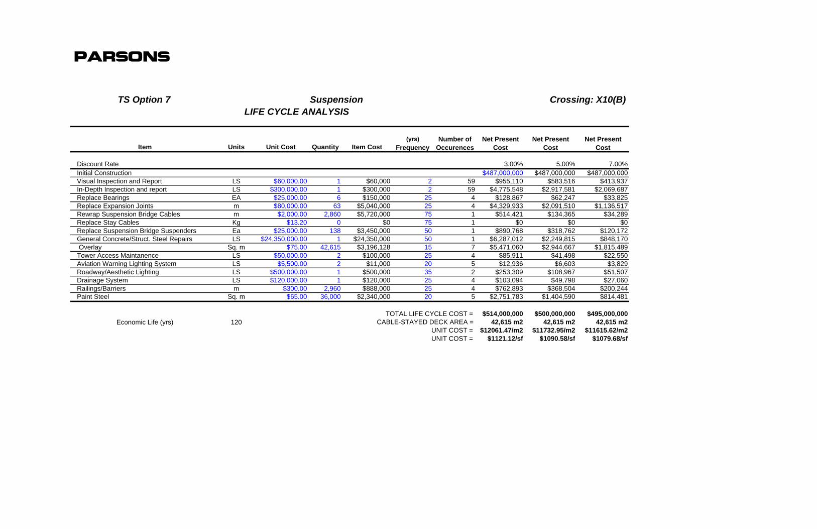
parsons
TS Option 7 Suspension Crossing: X10(B)
(yrs) Number of Net Present Net Present Net PresentItem Units Unit Cost Quantity Item Cost Frequency Occurences Cost Cost Cost
Discount Rate 3.00% 5.00% 7.00%Initial Construction $487,000,000 $487,000,000 $487,000,000Visual Inspection and Report LS $60,000.00 1 $60,000 2 59 $955,110 $583,516 $413,937In-Depth Inspection and report LS $300,000.00 1 $300,000 2 59 $4,775,548 $2,917,581 $2,069,687Replace Bearings EA $25,000.00 6 $150,000 25 4 $128,867 $62,247 $33,825Replace Expansion Joints m $80,000.00 63 $5,040,000 25 4 $4,329,933 $2,091,510 $1,136,517Rewrap Suspension Bridge Cables m $2,000.00 2,860 $5,720,000 75 1 $514,421 $134,365 $34,289Replace Stay Cables Kg $13.20 0 $0 75 1 $0 $0 $0Replace Suspension Bridge Suspenders Ea $25,000.00 138 $3,450,000 50 1 $890,768 $318,762 $120,172General Concrete/Struct. Steel Repairs LS $24,350,000.00 1 $24,350,000 50 1 $6,287,012 $2,249,815 $848,170 Overlay Sq. m $75.00 42,615 $3,196,128 15 7 $5,471,060 $2,944,667 $1,815,489Tower Access Maintanence LS $50,000.00 2 $100,000 25 4 $85,911 $41,498 $22,550Aviation Warning Lighting System LS $5,500.00 2 $11,000 20 5 $12,936 $6,603 $3,829Roadway/Aesthetic Lighting LS $500,000.00 1 $500,000 35 2 $253,309 $108,967 $51,507Drainage System LS $120,000.00 1 $120,000 25 4 $103,094 $49,798 $27,060Railings/Barriers m $300.00 2,960 $888,000 25 4 $762,893 $368,504 $200,244Paint Steel Sq. m $65.00 36,000 $2,340,000 20 5 $2,751,783 $1,404,590 $814,481
TOTAL LIFE CYCLE COST = $514,000,000 $500,000,000 $495,000,000Economic Life (yrs) 120 CABLE-STAYED DECK AREA = 42,615 m2 42,615 m2 42,615 m2
UNIT COST = $12061.47/m2 $11732.95/m2 $11615.62/m2UNIT COST = $1121.12/sf $1090.58/sf $1079.68/sf
LIFE CYCLE ANALYSIS

parsons
TS Option 9 Cable Stayed Crossing: X11(C)
(yrs) Number of Net Present Net Present Net PresentItem Units Unit Cost Quantity Item Cost Frequency Occurences Cost Cost Cost
Discount Rate 3.00% 5.00% 7.00%Initial Construction $377,000,000 $377,000,000 $377,000,000Visual Inspection and Report LS $60,000.00 1 $60,000 2 59 $955,110 $583,516 $413,937In-Depth Inspection and report LS $300,000.00 1 $300,000 2 59 $4,775,548 $2,917,581 $2,069,687Replace Bearings EA $10,000.00 24 $240,000 25 4 $206,187 $99,596 $54,120Replace Expansion Joints m $80,000.00 63 $5,040,000 25 4 $4,329,933 $2,091,510 $1,136,517Rewrap Suspension Bridge Cables m $2,000.00 0 $0 75 1 $0 $0 $0Replace Stay Cables Kg $13.20 2,286,173 $30,177,484 75 1 $2,713,974 $708,880 $180,900Replace Suspension Bridge Suspenders Ea $25,000.00 0 $0 50 1 $0 $0 $0General Concrete/Struct. Steel Repairs LS $18,850,000.00 1 $18,850,000 50 1 $4,866,948 $1,741,643 $656,591 Overlay Sq. m $75.00 42,867 $3,215,040 15 7 $5,503,433 $2,962,091 $1,826,231Tower Access Maintanence LS $50,000.00 2 $100,000 25 4 $85,911 $41,498 $22,550Aviation Warning Lighting System LS $5,500.00 2 $11,000 20 5 $12,936 $6,603 $3,829Roadway/Aesthetic Lighting LS $500,000.00 1 $500,000 35 2 $253,309 $108,967 $51,507Drainage System LS $120,000.00 1 $120,000 25 4 $103,094 $49,798 $27,060Railings/Barriers m $300.00 2,720 $816,000 25 4 $701,037 $338,625 $184,008Paint Steel Sq. m $65.00 33,500 $2,177,500 20 5 $2,560,687 $1,307,049 $757,920
TOTAL LIFE CYCLE COST = $404,000,000 $390,000,000 $384,000,000Economic Life (yrs) 120 CABLE-STAYED DECK AREA = 42,867 m2 42,867 m2 42,867 m2
UNIT COST = $9424.46/m2 $9097.87/m2 $8957.90/m2UNIT COST = $876.01/sf $845.65/sf $832.64/sf
LIFE CYCLE ANALYSIS
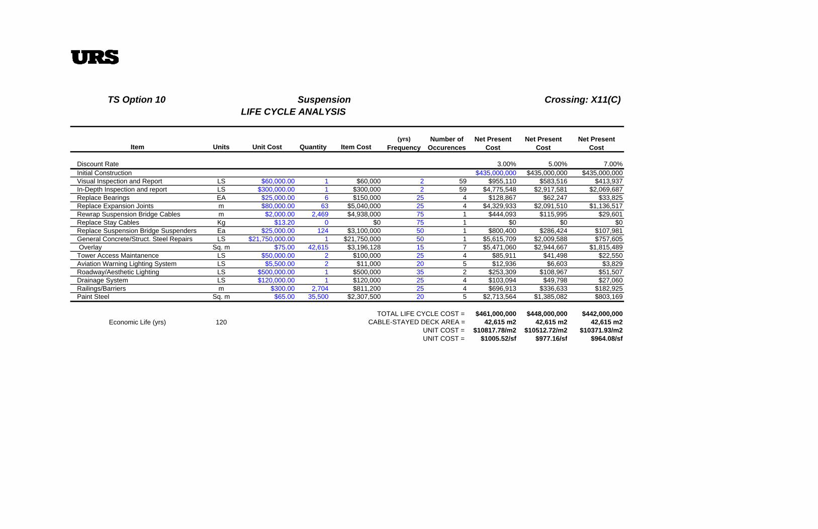
TS Option 10 Suspension Crossing: X11(C)
(yrs) Number of Net Present Net Present Net PresentItem Units Unit Cost Quantity Item Cost Frequency Occurences Cost Cost Cost
Discount Rate 3.00% 5.00% 7.00%Initial Construction $435,000,000 $435,000,000 $435,000,000Visual Inspection and Report LS $60,000.00 1 $60,000 2 59 $955,110 $583,516 $413,937In-Depth Inspection and report LS $300,000.00 1 $300,000 2 59 $4,775,548 $2,917,581 $2,069,687Replace Bearings EA $25,000.00 6 $150,000 25 4 $128,867 $62,247 $33,825Replace Expansion Joints m $80,000.00 63 $5,040,000 25 4 $4,329,933 $2,091,510 $1,136,517Rewrap Suspension Bridge Cables m $2,000.00 2,469 $4,938,000 75 1 $444,093 $115,995 $29,601Replace Stay Cables Kg $13.20 0 $0 75 1 $0 $0 $0Replace Suspension Bridge Suspenders Ea $25,000.00 124 $3,100,000 50 1 $800,400 $286,424 $107,981General Concrete/Struct. Steel Repairs LS $21,750,000.00 1 $21,750,000 50 1 $5,615,709 $2,009,588 $757,605 Overlay Sq. m $75.00 42,615 $3,196,128 15 7 $5,471,060 $2,944,667 $1,815,489Tower Access Maintanence LS $50,000.00 2 $100,000 25 4 $85,911 $41,498 $22,550Aviation Warning Lighting System LS $5,500.00 2 $11,000 20 5 $12,936 $6,603 $3,829Roadway/Aesthetic Lighting LS $500,000.00 1 $500,000 35 2 $253,309 $108,967 $51,507Drainage System LS $120,000.00 1 $120,000 25 4 $103,094 $49,798 $27,060Railings/Barriers m $300.00 2,704 $811,200 25 4 $696,913 $336,633 $182,925Paint Steel Sq. m $65.00 35,500 $2,307,500 20 5 $2,713,564 $1,385,082 $803,169
TOTAL LIFE CYCLE COST = $461,000,000 $448,000,000 $442,000,000Economic Life (yrs) 120 CABLE-STAYED DECK AREA = 42,615 m2 42,615 m2 42,615 m2
UNIT COST = $10817.78/m2 $10512.72/m2 $10371.93/m2UNIT COST = $1005.52/sf $977.16/sf $964.08/sf
LIFE CYCLE ANALYSIS