configuring circuit emulation over packet · configuring circuit emulation overpacket...
TRANSCRIPT

Configuring Circuit Emulation over Packet
This module describes the configuration of Circuit Emulation over Packet (CEoP) shared port adapters (SPAs)on the Cisco ASR 9000 Series Aggregation Services Routers.
Feature History for Configuring CEoP on Cisco ASR 9000 Series Router
ModificationRelease
• Support for Circuit Emulation Service overPacket SwitchedNetworkwas added in this SPA:
• Cisco 1-port ChannelizedOC3/STM-1 SPA(SPA-1CHOC3-CE-ATM)
Release 4.2.0
• Support for Circuit Emulation Service overPacket Switched Network was added in theseSPAs:
• Cisco 24-Port Channelized T1/E1 CircuitEmulation and Channelized ATM SPA(SPA-24CHT1-CE-ATM )
• Cisco 2-Port Channelized T3/E3 CircuitEmulation and Channelized ATM SPA(SPA-2CHT3-CE-ATM)
Release 4.3.0
• Configuring Circuit Emulation over Packet, on page 2• Prerequisites for Configuration, on page 2• Overview of Circuit Emulation over Packet Service, on page 3• Information About Configuring CEoP Channelized SONET/SDH, on page 4• Clock Distribution, on page 8• How to implement CEM, on page 10• Configuration Examples for CEM, on page 35
Configuring Circuit Emulation over Packet1
Configuring Circuit Emulation over PacketThis module describes the configuration of Circuit Emulation over Packet (CEoP) shared port adapters (SPAs)on the Cisco ASR 9000 Series Aggregation Services Routers.
Feature History for Configuring CEoP on Cisco ASR 9000 Series Router
ModificationRelease
• Support for Circuit Emulation Service overPacket SwitchedNetworkwas added in this SPA:
• Cisco 1-port ChannelizedOC3/STM-1 SPA(SPA-1CHOC3-CE-ATM)
Release 4.2.0
• Support for Circuit Emulation Service overPacket Switched Network was added in theseSPAs:
• Cisco 24-Port Channelized T1/E1 CircuitEmulation and Channelized ATM SPA(SPA-24CHT1-CE-ATM )
• Cisco 2-Port Channelized T3/E3 CircuitEmulation and Channelized ATM SPA(SPA-2CHT3-CE-ATM)
Release 4.3.0
Prerequisites for ConfigurationYou must be in a user group associated with a task group that includes the proper task IDs. The commandreference guides include the task IDs required for each command. If you suspect user group assignment ispreventing you from using a command, contact your AAA administrator for assistance.
Before configuring the Circuit Emulation over Packet (CEoP) service on your router, ensure that theseconditions are met:
• You must have one of these SPAs installed in your chassis:
• Cisco 2-Port Channelized T3/E3 Circuit Emulation and Channelized ATM SPA
• Cisco 24-Port Channelized T1/E1 Circuit Emulation and Channelized ATM SPA
• Cisco 1-port Channelized OC3/STM-1 Circuit Emulation and ATM SPA
• You should know how to apply and specify the SONET controller name and interface-path-id with thegeneralized notation rack/slot/module/port. The SONET controller name and interface-path-id are requiredwith the controller sonet command.
Configuring Circuit Emulation over Packet2
Configuring Circuit Emulation over PacketConfiguring Circuit Emulation over Packet
• You should know how to apply and specify the T3/E3 and T1/E1 controller name and interface-path-idwith the generalized notation rack/slot/module/port. The T3/E3, T1/E1 controller name andinterface-path-id are required with the controller {T3|E3|T1|E1} command.
Overview of Circuit Emulation over Packet ServiceCircuit Emulation over Packet (CEoP) is a way to carry TDM circuits over packet switched network. CircuitEmulation over Packet is an imitation of a physical connection. The goal of CEoP is to replace leased linesand legacy TDM networks. This feature allows network administrators to use their existing IP or MPLSnetwork to provide leased-line emulation services or to carry data streams or protocols that do not meet theformat requirements of other multiservice platform interfaces. CEoP puts TDMbits into packets, encapsulatesthem into an appropriate header and then sends that through PSN. The receiver side of CEoP restores theTDM bit stream from packets.
CEoP SPAs are half-height (HH) Shared Port Adapters (SPA) and the CEoP SPA family consists of24xT1/E1/J1, 2xT3/E3, and 1xOC3/STM1 unstructured and structured (NxDS0) quarter rate, half heightSPAs. The CEoP SPAs provide bit-transparent data transport that is completely protocol independent.
CEoP has two major modes:
• Unstructured mode is called SAToP (Structure Agnostic TDM over Packet) — SAToP does not lookwhat is inside the incoming data and considers it as a pure bit stream.
• Structured mode is named CESoPSN (Circuit Emulation Service over Packet Switched Network) —CESoPSN is aware of the structure of the incoming TDM bit stream at DS0 level.
CESoPSN and SAToP can use MPLS, UDP/IP, and L2TPv3 for the underlying transport mechanism.
The Cisco IOS XR Release 4.2.x supports only MPLS transport mechanism.Note
These SPAs are the first Cisco router interfaces designed to meet the emerging standards for Circuit EmulationServices over Packet Switched Network (CESoPSN) and Structure-Agnostic Transport over Packet (SAToP)transport.
In SAToP mode, these SPAs do not assume that data has any predefined format or structure. They simplyregard the data as an arbitrary bit stream. All data bits are simply transported to a defined destinationencapsulated in IP/MPLS packets. In CESoPSN mode the carrier has defined format. The SPAs support a fullrange of E1 and T1 framing. CESoPSN applications can save utilized bandwidth by selecting only validtimeslots for transmission. Some primary applications include:
• Transporting 2G and 3G network traffic over packet networks, for mobile operators. Mobile serviceproviders are implementing high-speed data networks with HSDPA to support new revenue-generatingservices. The SPA is uniquely positioned for multigenerational migration of mobile networks (2G and3G), simultaneously carrying TDM and ATM traffic over IP/MPLS networks. This technology providesa mechanism to enable IP/MPLS to the cell site, which can eventually be in place to transport the mobiletraffic over IP from end to end.
• T3/E3 circuit emulation for leased-line replacement.
• T1/E1 circuit emulation for leased-line replacement.
Configuring Circuit Emulation over Packet3
Configuring Circuit Emulation over PacketOverview of Circuit Emulation over Packet Service
• PBX to PBX connectivity over PSN.
• High density SS7 backhaul over IP/MPLS.
• Inter-MSC connectivity.
• Preencrypted data for government, defense, or other high-security applications.
• Proprietary synchronous or asynchronous data protocols used in transportation, utilities, and otherindustries.
• Leased-line emulation service offerings in metropolitan (metro) Ethernet or WAN service providerenvironments.
For more information on Circuit Emulation service concepts, configuration, and example, see the ImplementingPoint to Point Layer 2 Services module in the Cisco ASR 9000 Series Aggregation Services Router L2VPNand Ethernet Services Configuration Guide.
Information About Configuring CEoP Channelized SONET/SDHTo configure the Circuit Emulation over Packet Channelized SONET/SDH, youmust understand the followingconcepts:
Channelized SONET and SDH OverviewSynchronous Optical Network (SONET) is an American National Standards Institute (ANSI) specificationformat used in transporting digital telecommunications services over optical fiber.
Channelized SONET provides the ability to transport SONET frames across multiplexed T3/E3 and virtualtributary group (VTG) channels.
SONET uses Synchronous Transport Signal (STS) framing. An STS is the electrical equivalent to an opticalcarrier 1 (OC-1).
A channelized SONET interface is a composite of STS streams, which are maintained as independent frameswith unique payload pointers. The frames are multiplexed before transmission.
When a line is channelized, it is logically divided into smaller bandwidth channels called paths. These pathscarry the SONET payload. The sum of the bandwidth on all paths cannot exceed the line bandwidth.
When a line is not channelized, it is called clear channel, and the full bandwidth of the line is dedicated to asingle channel that carries broadband services.
The T3/E3 channels can be channelized into T1s, and the T1s can be channelized further into DS0 time slots.
Channelizing a SONET line consists of two primary processes:
• Configuring the controller
• Configuring the interface into channelized paths
You configure the controller first by setting the mode of the STS path.
When the mode is specified, the respective controller is created, and the remainder of the configuration isapplied on that controller. For example, mode T3 creates a T3 controller. The T3 controller can then be
Configuring Circuit Emulation over Packet4
Configuring Circuit Emulation over PacketInformation About Configuring CEoP Channelized SONET/SDH
configured to a serial channel, or it can be further channelized to carry T1s, and those T1s can be configuredto serial interfaces.
Depending on the support for your installed SPA, each STS path can be independently configured into T3s,E3s, or VTGs, and so on.
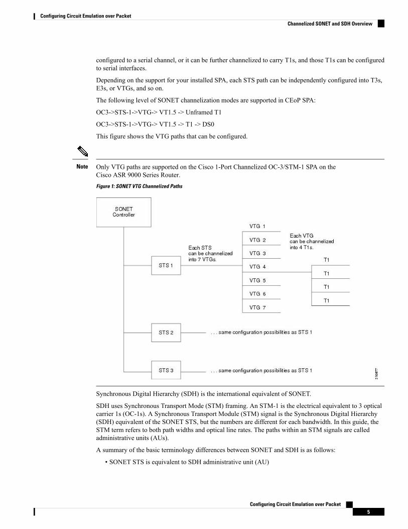
The following level of SONET channelization modes are supported in CEoP SPA:
OC3->STS-1->VTG-> VT1.5 -> Unframed T1
OC3->STS-1->VTG-> VT1.5 -> T1 -> DS0
This figure shows the VTG paths that can be configured.
Only VTG paths are supported on the Cisco 1-Port Channelized OC-3/STM-1 SPA on theCisco ASR 9000 Series Router.Figure 1: SONET VTG Channelized Paths
Note
Synchronous Digital Hierarchy (SDH) is the international equivalent of SONET.
SDH uses Synchronous Transport Mode (STM) framing. An STM-1 is the electrical equivalent to 3 opticalcarrier 1s (OC-1s). A Synchronous Transport Module (STM) signal is the Synchronous Digital Hierarchy(SDH) equivalent of the SONET STS, but the numbers are different for each bandwidth. In this guide, theSTM term refers to both path widths and optical line rates. The paths within an STM signals are calledadministrative units (AUs).
A summary of the basic terminology differences between SONET and SDH is as follows:
• SONET STS is equivalent to SDH administrative unit (AU)
Configuring Circuit Emulation over Packet5
Configuring Circuit Emulation over PacketChannelized SONET and SDH Overview
• SONET VT is equivalent to SDH tributary unit (TU)
• SDH basic building blocks are STM-1 (equivalent to STS-3) and STM-0 (equivalent to STS-1)
An administrative unit (AU) is the information structure that provides adaptation between the higher-orderpath layer and the multiplex section layer. It consists of an information payload (the higher-order virtualcontainer) and an administrative unit pointer, which indicates the offset of the payload frame start relative tothe multiplex section frame start.
An AU can be channelized into tributary units (TUs) and tributary unit groups (TUGs).
An administrative unit 3 (AU-3) consists of one STM-1.
An administrative unit group (AUG) consists of one or more administrative units occupying fixed, definedpositions in an STM payload.
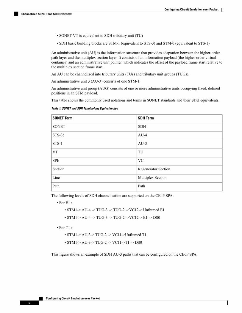
This table shows the commonly used notations and terms in SONET standards and their SDH equivalents.
Table 1: SONET and SDH Terminology Equivalencies
SDH TermSONET Term
SDHSONET
AU-4STS-3c
AU-3STS-1
TUVT
VCSPE
Regenerator SectionSection
Multiplex SectionLine
PathPath
The following levels of SDH channelization are supported on the CEoP SPA:
• For E1 :
• STM1-> AU-4 -> TUG-3 -> TUG-2 ->VC12-> Unframed E1
• STM1-> AU-4 -> TUG-3 -> TUG-2 ->VC12-> E1 -> DS0
• For T1 :
• STM1-> AU-3-> TUG-2 -> VC11->Unframed T1
• STM1-> AU-3-> TUG-2 -> VC11->T1 -> DS0
This figure shows an example of SDH AU-3 paths that can be configured on the CEoP SPA.
Configuring Circuit Emulation over Packet6
Configuring Circuit Emulation over PacketChannelized SONET and SDH Overview

Figure 2: SDH AU3 Paths
This figure shows the SDH AU4 paths that can be configured on the CEoP SPA.
Configuring Circuit Emulation over Packet7
Configuring Circuit Emulation over PacketChannelized SONET and SDH Overview
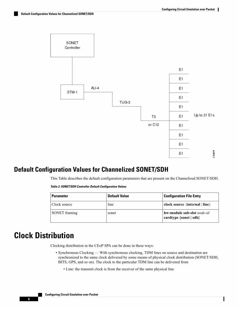
Default Configuration Values for Channelized SONET/SDHThis Table describes the default configuration parameters that are present on the Channelized SONET/SDH.
Table 2: SONET/SDH Controller Default Configuration Values
Configuration File EntryDefault ValueParameter
clock source {internal | line}lineClock source
hw-module sub-slot node-idcardtype {sonet | sdh}
sonetSONET framing
Clock DistributionClocking distribution in the CEoP SPA can be done in these ways:
• Synchronous Clocking —With synchronous clocking, TDM lines on source and destination aresynchronized to the same clock delivered by some means of physical clock distribution (SONET/SDH,BITS, GPS, and so on). The clock to the particular TDM line can be delivered from
• Line: the transmit clock is from the receiver of the same physical line
Configuring Circuit Emulation over Packet8
Configuring Circuit Emulation over PacketDefault Configuration Values for Channelized SONET/SDH

• Internal: the transmit clock is taken from line card and can be derived either from an internal freerunning oscillator or from another physical line
• Recovered: In-band pseudowire-based activeclock recovery on a CEM interface which is used todrive the transmit clock.
The number of recovered clocks that can be configured for CEoP SPA are:
• Cisco 24-Port Channelized T1/E1 Circuit Emulation and Channelized ATM SPA : 24 clocks for eachSPA.
• Cisco 2-Port Channelized T3/E3 Circuit Emulation and Channelized ATM SPA : 10 clocks for each SPAin the T1/E1 mode and 2 clocks for each SPA in the T3/E3 mode.
• Cisco 1-port Channelized OC3/STM-1 Circuit Emulation and Channelized ATM SPA : 10 clocks perSPA in the T1/E1 mode.
• Adaptive Clocking — Adaptive clocking is used when the routers do not have a common clock source.See this figure. The clock is derived based on packet arrival rates. Two major types of adaptive clockrecovery algorithms are:
• Based on dejitter buffer fill level
• Based on packet arrival rate
The clock quality depends on packet size, has less tolerance to packet loss/corruption and introduces unnecessarydelay in order to have sufficient number of packets in the buffer for clock recovery. The dejitter buffer sizedetermines the ability of the emulated circuit to tolerate network jitter. The dejitter buffer in CEoP softwareis configurable up to a maximum of 500 milliseconds.
The CEoP SPA hardware supports only the packet arrival rate algorithm.Note
Figure 3: Adaptive Clock Recovery
• Differential clocking — Differential clocking is used when the cell site and aggregation routers have acommon clock source but TDM lines are clocked by a different source. The TDM clocks are derivedfrom differential information in the RTP header of the packet with respect to the common clock.Differential clock recovery is based on time stamps received in RTP header. On the master side, thedifference of TDM clock and network clock is recorded into RTP header. On the slave side, thesetimestamps are read fromRTP header, the clock recovery is done and this clock is used for synchronization.See Figure 5.
The Cisco 1-port Channelized OC3/STM-1 CEoP SPA hardware can recover only a maximum of ten uniqueclocks in as many CEM interfaces. The CEM interfaces where clock recovery is configured must be on uniqueT1s.
Note
For information on CEM configuration and commands, see Implementing Point to Point Layer 2 Servicesmodule in theCisco ASR 9000 Series Aggregation Services Router L2VPN and Ethernet Services Configuration
Configuring Circuit Emulation over Packet9
Configuring Circuit Emulation over PacketClock Distribution

Guide and Cisco ASR 9000 Series Aggregation Services Router L2VPN and Ethernet Services CommandReference.
For a sample CEM interface configuration, refer Circuit Emulation Interface Configuration: Examples.
How to implement CEMThis section contains the following procedures:
Configuring SONET VT1.5-Mapped T1 Channels and Creating CEM InterfaceIn the case of Cisco 1-port Channelized OC3/STM-1 CEoP SPA, the STS stream can be channelized into theVT1.5 mapped T1 channel.
This task explains how to configure a SONET line into VT-mapped T1 Channels.
Before you begin
None.
Restrictions
Channelized SONET STS stream with VT1.5-T1 mapping is supported on the following SPA:
• Cisco 1-Port Channelized OC-3/STM-1 SPA
SUMMARY STEPS
1. configure2. hw-module subslot node-id cardtype {sonet| sdh}3. commit4. controller sonet interface-path-id5. sts number6. mode mode7. root8. controller t1 interface-path-id9. cem-group unframed10. controller t1 interface-path-id11. cem-group framed group-number timeslots range1-range212. no shutdown13. end or commit14. show runn interface cem interface-path-id
DETAILED STEPS
PurposeCommand or Action
Enters global configuration mode.configure
Example:
Step 1
Configuring Circuit Emulation over Packet10
Configuring Circuit Emulation over PacketHow to implement CEM

PurposeCommand or Action
RP/0/RSP0/CPU0:router# configure
Configures the controller for SONET framing.hw-module subslot node-id cardtype {sonet| sdh}Step 2
Example: SONET framing (sonet) is the default. Whenever there isa change in framing mode (sonet/sdh), the SPA will be
RP/0/RSP0/CPU0:router(config-sonet)# hw-modulesubslot 0/3/0 sonet
reloaded automatically. Reload will happen only when allthe CEM Interface, T1 Controller and Sonet Controllerconfigurations are removed completely. This is notapplicable when you configure the first time because T1controller and interface configurations would not exist.
This configuration is mandatory for CEoP SPA to worknormally in one of the framingmodes.When you configurefor the first time, it will not cause a SPA reload, if thecardtype is set to Sonet.
Use the commit command to save the configurationchanges to the running configuration file and remain withinthe configuration session.
commitStep 3
Enters controller configuration submode and specifies theSONET controller name and instance identifier with therack/slot/module/port/controllerName notation.
controller sonet interface-path-idStep 4
Configures the STS stream specified by number. The rangeis from1 to 3.
sts number
Example:
Step 5
RP/0/RSP0/CPU0:router(config-sonet)# sts 1
Sets the mode of interface at the STS level. The possiblemodes are:
mode mode
Example:
Step 6
• vt15-t1—SONET path carrying virtual tributary 1.5T1s (VT15 T1)RP/0/RSP0/CPU0:router(config-stsPath)# mode t1
Exits to global configuration mode. Go to step 7, if youwant to create an structure agnostic CEM interface. Go to
root
Example:
Step 7
step 9, if you want to create a structure aware CEMinterface.
RP/0/RSP0/CPU0:router(config-stsPath)# root
Enters T1 controller configuration submode and specifiesthe T1 controller name and interface-path-id with therack/slot/module/port/sts-num/vtg-num/T1-num notation.
controller t1 interface-path-id
Example:
RP/0/RSP0/CPU0:router(config)# controller t10/0/1/0/1/4/1
Step 8
Creates an structure agnostic CEM interface.cem-group unframed
Example:
Step 9
Configuring Circuit Emulation over Packet11
Configuring Circuit Emulation over PacketConfiguring SONET VT1.5-Mapped T1 Channels and Creating CEM Interface
PurposeCommand or Action
RP/0/RSP0/CPU0:router(config)# cem-group unframed
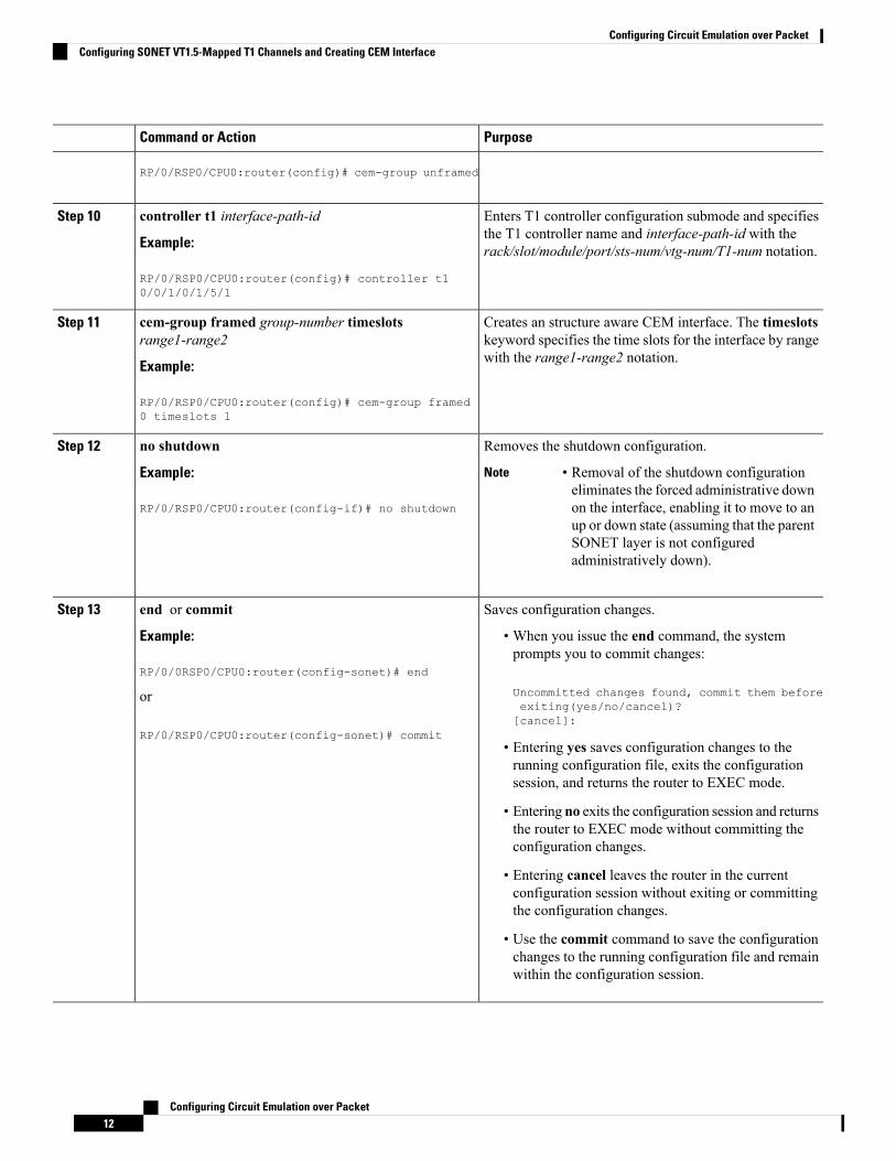
Enters T1 controller configuration submode and specifiesthe T1 controller name and interface-path-id with therack/slot/module/port/sts-num/vtg-num/T1-num notation.
controller t1 interface-path-id
Example:
RP/0/RSP0/CPU0:router(config)# controller t10/0/1/0/1/5/1
Step 10
Creates an structure aware CEM interface. The timeslotskeyword specifies the time slots for the interface by rangewith the range1-range2 notation.
cem-group framed group-number timeslotsrange1-range2
Example:
Step 11
RP/0/RSP0/CPU0:router(config)# cem-group framed0 timeslots 1
Removes the shutdown configuration.no shutdownStep 12
Example: • Removal of the shutdown configurationeliminates the forced administrative downon the interface, enabling it to move to anup or down state (assuming that the parentSONET layer is not configuredadministratively down).
Note
RP/0/RSP0/CPU0:router(config-if)# no shutdown
Saves configuration changes.end or commitStep 13
Example: • When you issue the end command, the systemprompts you to commit changes:
RP/0/0RSP0/CPU0:router(config-sonet)# end
Uncommitted changes found, commit them beforeorexiting(yes/no/cancel)?[cancel]:
RP/0/RSP0/CPU0:router(config-sonet)# commit• Entering yes saves configuration changes to therunning configuration file, exits the configurationsession, and returns the router to EXEC mode.
• Entering no exits the configuration session and returnsthe router to EXEC mode without committing theconfiguration changes.
• Entering cancel leaves the router in the currentconfiguration session without exiting or committingthe configuration changes.
• Use the commit command to save the configurationchanges to the running configuration file and remainwithin the configuration session.
Configuring Circuit Emulation over Packet12
Configuring Circuit Emulation over PacketConfiguring SONET VT1.5-Mapped T1 Channels and Creating CEM Interface
PurposeCommand or Action
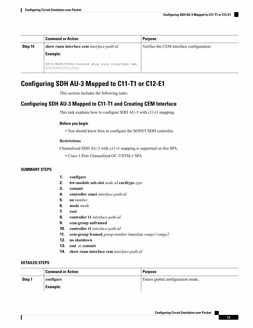
Verifies the CEM interface configuration.show runn interface cem interface-path-id
Example:
Step 14
RP/0/RSP0/CPU0:router# show runn interface cem0/0/2/0/1/1/1/1:1
Configuring SDH AU-3 Mapped to C11-T1 or C12-E1This section includes the following tasks:
Configuring SDH AU-3 Mapped to C11-T1 and Creating CEM InterfaceThis task explains how to configure SDH AU-3 with c11-t1 mapping.
Before you begin
• You should know how to configure the SONET/SDH controller.
Restrictions
Channelized SDH AU-3 with c11-t1 mapping is supported on this SPA:
• Cisco 1-Port Channelized OC-3/STM-1 SPA
SUMMARY STEPS
1. configure2. hw-module sub-slot node-id cardtype type3. commit4. controller sonet interface-path-id5. au number6. mode mode7. root8. controller t1 interface-path-id9. cem-group unframed10. controller t1 interface-path-id11. cem-group framed group-number timeslots range1-range212. no shutdown13. end or commit14. show runn interface cem interface-path-id
DETAILED STEPS
PurposeCommand or Action
Enters global configuration mode.configure
Example:
Step 1
Configuring Circuit Emulation over Packet13
Configuring Circuit Emulation over PacketConfiguring SDH AU-3 Mapped to C11-T1 or C12-E1
PurposeCommand or Action
RP/0/RSP0/CPU0:router# configure
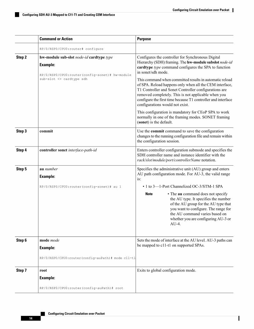
Configures the controller for Synchronous DigitalHierarchy (SDH) framing. Thehw-module subslot node-id
hw-module sub-slot node-id cardtype type
Example:
Step 2
cardtype type command configures the SPA to functionin sonet/sdh mode.
RP/0/RSP0/CPU0:router(config-sonet)# hw-modulesub-slot <> cardtype sdh This commandwhen committed results in automatic reload
of SPA. Reload happens only when all the CEM interface,T1 Controller and Sonet Controller configurations areremoved completely. This is not applicable when youconfigure the first time because T1 controller and interfaceconfigurations would not exist.
This configuration is mandatory for CEoP SPA to worknormally in one of the framing modes. SONET framing(sonet) is the default.
Use the commit command to save the configurationchanges to the running configuration file and remain withinthe configuration session.
commitStep 3
Enters controller configuration submode and specifies theSDH controller name and instance identifier with therack/slot/module/port/controllerName notation.
controller sonet interface-path-idStep 4
Specifies the administrative unit (AU) group and entersAU path configuration mode. For AU-3, the valid rangeis:
au number
Example:
RP/0/RSP0/CPU0:router(config-sonet)# au 1
Step 5
• 1 to 3—1-Port Channelized OC-3/STM-1 SPA
• The au command does not specifythe AU type. It specifies the numberof the AU group for the AU type thatyou want to configure. The range forthe AU command varies based onwhether you are configuring AU-3 orAU-4.
Note
Sets the mode of interface at the AU level. AU-3 paths canbe mapped to c11-t1 on supported SPAs.
mode mode
Example:
Step 6
RP/0/RSP0/CPU0:router(config-auPath)# mode c11-t1
Exits to global configuration mode.root
Example:
Step 7
RP/0/RSP0/CPU0:router(config-auPath)# root
Configuring Circuit Emulation over Packet14
Configuring Circuit Emulation over PacketConfiguring SDH AU-3 Mapped to C11-T1 and Creating CEM Interface
PurposeCommand or Action
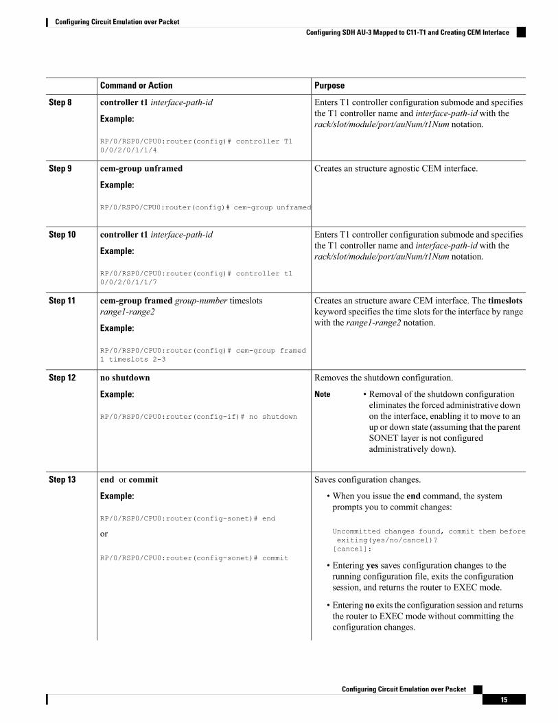
Enters T1 controller configuration submode and specifiesthe T1 controller name and interface-path-id with therack/slot/module/port/auNum/t1Num notation.
controller t1 interface-path-id
Example:
RP/0/RSP0/CPU0:router(config)# controller T10/0/2/0/1/1/4
Step 8
Creates an structure agnostic CEM interface.cem-group unframed
Example:
Step 9
RP/0/RSP0/CPU0:router(config)# cem-group unframed
Enters T1 controller configuration submode and specifiesthe T1 controller name and interface-path-id with therack/slot/module/port/auNum/t1Num notation.
controller t1 interface-path-id
Example:
RP/0/RSP0/CPU0:router(config)# controller t10/0/2/0/1/1/7
Step 10
Creates an structure aware CEM interface. The timeslotskeyword specifies the time slots for the interface by rangewith the range1-range2 notation.
cem-group framed group-number timeslotsrange1-range2
Example:
Step 11
RP/0/RSP0/CPU0:router(config)# cem-group framed1 timeslots 2-3
Removes the shutdown configuration.no shutdownStep 12
Example: • Removal of the shutdown configurationeliminates the forced administrative downon the interface, enabling it to move to anup or down state (assuming that the parentSONET layer is not configuredadministratively down).
Note
RP/0/RSP0/CPU0:router(config-if)# no shutdown
Saves configuration changes.end or commitStep 13
Example: • When you issue the end command, the systemprompts you to commit changes:
RP/0/RSP0/CPU0:router(config-sonet)# end
Uncommitted changes found, commit them beforeorexiting(yes/no/cancel)?[cancel]:
RP/0/RSP0/CPU0:router(config-sonet)# commit• Entering yes saves configuration changes to therunning configuration file, exits the configurationsession, and returns the router to EXEC mode.
• Entering no exits the configuration session and returnsthe router to EXEC mode without committing theconfiguration changes.
Configuring Circuit Emulation over Packet15
Configuring Circuit Emulation over PacketConfiguring SDH AU-3 Mapped to C11-T1 and Creating CEM Interface

PurposeCommand or Action
• Entering cancel leaves the router in the currentconfiguration session without exiting or committingthe configuration changes.
• Use the commit command to save the configurationchanges to the running configuration file and remainwithin the configuration session.
Verifies the CEM interface configuration.show runn interface cem interface-path-id
Example:
Step 14
RP/0/RSP0/CPU0:router# show runn interface cem0/0/2/0/1/1/1/1:1
Configuring SDH AU-3 Mapped to C12-E1 and Creating CEM InterfaceThis task explains how to configure SDH AU-3 with c12-e1 mapping.
Before you begin
• You should know how to configure the SONET/SDH controller.
Restrictions
Channelized SDH AU-3 with c12-e1 mapping is supported on this SPA:
• Cisco 1-Port Channelized OC-3/STM-1 SPA
SUMMARY STEPS
1. configure2. hw-module sub-slot node-id cardtype type3. commit4. controller sonet interface-path-id5. au number6. mode tug37. width number8. tug3 number9. mode mode10. root11. controller e1 interface-path-id12. cem-group unframed13. controller e1 interface-path-id14. cem-group framed group-number timeslots range1-range215. no shutdown16. end or commit
Configuring Circuit Emulation over Packet16
Configuring Circuit Emulation over PacketConfiguring SDH AU-3 Mapped to C12-E1 and Creating CEM Interface

DETAILED STEPS
PurposeCommand or Action
Enters global configuration mode.configure
Example:
Step 1
RP/0/RSP0/CPU0:router# configure
Configures the controller framing for Synchronous DigitalHierarchy (SDH) framing. Thehw-module subslot node-id
hw-module sub-slot node-id cardtype type
Example:
Step 2
cardtype type command configures the SPA to function
RP/0/RSP0/CPU0:router(config-sonet)# hw-modulesub-slot <> cardtype sdh
in sonet/sdhmode. This commandwhen committed resultsin automatic reload of SPA. Reload happens only whenall the CEM interface, E1 Controller and Sonet Controllerconfigurations are removed completely.
Use the commit command to save the configurationchanges to the running configuration file and remain withinthe configuration session.
commitStep 3
Enters controller configuration submode and specifies theSDH controller name and instance identifier with therack/slot/module/port/controllerName notation.
controller sonet interface-path-idStep 4
Specifies the administrative unit (AU) group and entersAU path configuration mode. For AU-3, the valid rangeis:
au number
Example:
RP/0/RSP0/CPU0:router(config-sonet)# au 1
Step 5
• 1 to 3—1-Port Channelized OC-3/STM-1 SPA
• The au command does not specifythe AU type. It specifies the numberof the AU group for the AU type thatyou want to configure. The range forthe AU command varies based onwhether you are configuring AU-3 orAU-4.
Note
Sets the mode of interface at the AU level. Currently onlyTUG3 is supported.
mode tug3
Example:
Step 6
RP/0/RSP0/CPU0:router(config-auPath)# mode tug3
Configures the number of the AU streams.width number
Example:
Step 7
RP/0/RSP0/CPU0:router(config-auPath)# width 3
Specifies the Tributary Unit Group (TUG) number andenters the config-tug3Path mode. The range is 1 to 3.
tug3 number
Example:
Step 8
Configuring Circuit Emulation over Packet17
Configuring Circuit Emulation over PacketConfiguring SDH AU-3 Mapped to C12-E1 and Creating CEM Interface
PurposeCommand or Action
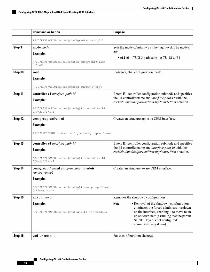
RP/0/RSP0/CPU0:router(config-auPath)#tug3 1
Sets the mode of interface at the tug3 level. The modesare:
mode mode
Example:
Step 9
• c12-e1—TUG-3 path carrying TU-12 to E1RP/0/RSP0/CPU0:router(config-tug3Path)# modec12-e1
Exits to global configuration mode.root
Example:
Step 10
RP/0/RSP0/CPU0:router(config-auPath)# root
Enters E1 controller configuration submode and specifiesthe E1 controller name and interface-path-id with therack/slot/module/port/auNum/tugNum/t1Num notation.
controller e1 interface-path-id
Example:
RP/0/RSP0/CPU0:router(config)# controller E10/0/2/0/1/1/1
Step 11
Creates an structure agnostic CEM interface.cem-group unframed
Example:
Step 12
RP/0/RSP0/CPU0:router(config)# cem-group unframed
Enters E1 controller configuration submode and specifiesthe E1 controller name and interface-path-id with therack/slot/module/port/auNum/tugNum/t1Num notation.
controller e1 interface-path-id
Example:
RP/0/RSP0/CPU0:router(config)# controller E10/0/2/0/1/1/7
Step 13
Creates an structure aware CEM interface.cem-group framed group-number timeslotsrange1-range2
Step 14
Example:
RP/0/RSP0/CPU0:router(config)# cem-group framed0 timeslots 1
Removes the shutdown configuration.no shutdownStep 15
Example: • Removal of the shutdown configurationeliminates the forced administrative downon the interface, enabling it to move to anup or down state (assuming that the parentSONET layer is not configuredadministratively down).
Note
RP/0/RSP0/CPU0:router(config-if)# no shutdown
Saves configuration changes.end or commitStep 16
Configuring Circuit Emulation over Packet18
Configuring Circuit Emulation over PacketConfiguring SDH AU-3 Mapped to C12-E1 and Creating CEM Interface

PurposeCommand or Action
Example: • When you issue the end command, the systemprompts you to commit changes:
RP/0/RSP0/CPU0:router(config-sonet)# end
Uncommitted changes found, commit them beforeorexiting(yes/no/cancel)?[cancel]:
RP/0/RSP0/CPU0:router(config-sonet)# commit• Entering yes saves configuration changes to therunning configuration file, exits the configurationsession, and returns the router to EXEC mode.
• Entering no exits the configuration session and returnsthe router to EXEC mode without committing theconfiguration changes.
• Entering cancel leaves the router in the currentconfiguration session without exiting or committingthe configuration changes.
• Use the commit command to save the configurationchanges to the running configuration file and remainwithin the configuration session.
Configuring the Cisco 24-Port Channelized T1/E1 Circuit Emulation andChannelized ATM SPA and Creating CEM Interface
This task explains how to configure the Cisco 24-Port Channelized T1/E1 Circuit Emulation and ChannelizedATM SPA.
SUMMARY STEPS
1. configure2. hw-module subslot node-id cardtype {t1| e1}3. controller t1|e1 interface-path-id4. cem-group unframed5. controller t1|e1 interface-path-id6. cem-group framed group-number timeslots range1-range27. no shutdown8. end or commit9. show runn interface cem interface-path-id
DETAILED STEPS
PurposeCommand or Action
Enters global configuration mode.configure
Example:
Step 1
Configuring Circuit Emulation over Packet19
Configuring Circuit Emulation over PacketConfiguring the Cisco 24-Port Channelized T1/E1 Circuit Emulation and Channelized ATM SPA and Creating CEM Interface

PurposeCommand or Action
RP/0/RSP0/CPU0:router# configure
The hw-module subslot node-id cardtype type commandconfigures the SPA to function in t1/e1 mode.
hw-module subslot node-id cardtype {t1| e1}
Example:
Step 2
Reload will happen only when all the CEM interface, T1Controller configurations are removed completely. This isRP/0/RSP0/CPU0:router(config-t1)# hw-module subslot
0/3/0 cardtype t1 not applicable when you configure the first time becauseT1 controller and interface configurations would not exist.
Enters T1 controller configuration submode and specifiesthe T1 controller name and interface-path-id with therack/slot/module/port/T1num notation.
controller t1|e1 interface-path-id
Example:
RP/0/RSP0/CPU0:router(config)# controller t10/0/1/0/1
Step 3
Creates an structure agnostic CEM interface.cem-group unframed
Example:
Step 4
RP/0/RSP0/CPU0:router(config-t1)# cem-groupunframed
Enters T1 controller configuration submode and specifiesthe T1 controller name and interface-path-id with therack/slot/module/port/T1num notation.
controller t1|e1 interface-path-id
Example:
RP/0/RSP0/CPU0:router(config)# controller t10/0/1/0/1
Step 5
Creates an structure aware CEM interface. The timeslotskeyword specifies the time slots for the interface by rangewith the range1-range2 notation.
cem-group framed group-number timeslots range1-range2
Example:
RP/0/RSP0/CPU0:router(config-t1)# cem-group framed0 timeslots 1
Step 6
Removes the shutdown configuration.no shutdownStep 7
Example: • Removal of the shutdown configurationeliminates the forced administrative downon the interface, enabling it to move to anup or down state.
Note
RP/0/RSP0/CPU0:router(config-if)# no shutdown
Saves configuration changes.end or commitStep 8
Example: • When you issue the end command, the system promptsyou to commit changes:
RP/0/RSP0/CPU0:router(config-t1)# end
Uncommitted changes found, commit them beforeorexiting(yes/no/cancel)?[cancel]:
RP/0/RSP0/CPU0:router(config-t1)# commit
Configuring Circuit Emulation over Packet20
Configuring Circuit Emulation over PacketConfiguring the Cisco 24-Port Channelized T1/E1 Circuit Emulation and Channelized ATM SPA and Creating CEM Interface

PurposeCommand or Action
• Entering yes saves configuration changes to therunning configuration file, exits the configurationsession, and returns the router to EXEC mode.
• Entering no exits the configuration session and returnsthe router to EXEC mode without committing theconfiguration changes.
• Entering cancel leaves the router in the currentconfiguration session without exiting or committingthe configuration changes.
• Use the commit command to save the configurationchanges to the running configuration file and remainwithin the configuration session.
Verifies the CEM interface configuration.show runn interface cem interface-path-id
Example:
Step 9
RP/0/RSP0/CPU0:router# show runn interface cem0/0/2/0/1:1
Configuring the Cisco 2-Port Channelized T3/E3 Circuit Emulation andChannelized ATM SPA and Creating CEM Interface
T3/E3 Channelization ModeThis task explains how to configure the Cisco 2-Port Channelized T3/E3 Circuit Emulation and ChannelizedATM SPA using T3 channelization.
The T3 channels can be channelized into T1s or E1s, and the T1s or E1s can be channelized further into DS0time slots, on the Cisco 2-Port Channelized T3/E3 Circuit Emulation and Channelized ATM SPA.
Note
SUMMARY STEPS
1. configure2. hw-module subslot node-id cardtype {t3| e3}3. commit4. controller {t3|e3} interface-path-id5. cem-group unframed6. no shutdown7. end or commit8. show runn interface cem interface-path-id
Configuring Circuit Emulation over Packet21
Configuring Circuit Emulation over PacketConfiguring the Cisco 2-Port Channelized T3/E3 Circuit Emulation and Channelized ATM SPA and Creating CEM Interface

DETAILED STEPS
PurposeCommand or Action
Enters global configuration mode.configure
Example:
Step 1
RP/0/RSP0/CPU0:router# configure
The hw-module subslot node-id cardtype type commandconfigures the SPA to function in t3/e3 mode.
hw-module subslot node-id cardtype {t3| e3}
Example:
Step 2
Whenever there is a change in framing mode (t3/e3), theSPA will be reloaded automatically. Reload will happenRP/0/RSP0/CPU0:router(config-t3)# hw-module subslot
0/3/0 cardtype t3 only when all the CEM Interface, T3 Controllerconfigurations are removed completely. This is notapplicable when you configure the first time because T3controller and interface configurations would not exist.
Use the commit command to save the configuration changesto the running configuration file and remain within theconfiguration session.
commitStep 3
Enters T3/E3 controller configuration submode and specifiesthe T3/E3 controller name and interface-path-id with therack/slot/module/port/T3Num notation.
controller {t3|e3} interface-path-id
Example:
RP/0/RSP0/CPU0:router(config)# controller t30/0/1/0/4
Step 4
Creates an structure agnostic CEM interface. Only theunframed CEM interface is supported in this mode.
cem-group unframed
Example:
Step 5
RP/0/RSP0/CPU0:router(config-t3)# cem-groupunframed
Removes the shutdown configuration.no shutdownStep 6
Example: Removal of the shutdown configuration eliminates theforced administrative down on the interface, enabling it tomove to an up or down state.RP/0/RSP0/CPU0:router(config-if)# no shutdown
Saves configuration changes.end or commitStep 7
Example: • When you issue the end command, the system promptsyou to commit changes:
RP/0/RSP0/CPU0:router(config-t3)# end
Uncommitted changes found, commit them beforeorexiting(yes/no/cancel)?[cancel]:
RP/0/RSP0/CPU0:router(config-t3)# commit• Entering yes saves configuration changes to therunning configuration file, exits the configurationsession, and returns the router to EXEC mode.
Configuring Circuit Emulation over Packet22
Configuring Circuit Emulation over PacketT3/E3 Channelization Mode
PurposeCommand or Action
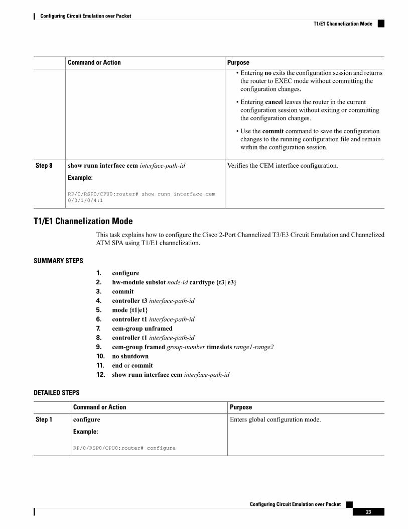
• Entering no exits the configuration session and returnsthe router to EXEC mode without committing theconfiguration changes.
• Entering cancel leaves the router in the currentconfiguration session without exiting or committingthe configuration changes.
• Use the commit command to save the configurationchanges to the running configuration file and remainwithin the configuration session.
Verifies the CEM interface configuration.show runn interface cem interface-path-id
Example:
Step 8
RP/0/RSP0/CPU0:router# show runn interface cem0/0/1/0/4:1
T1/E1 Channelization ModeThis task explains how to configure the Cisco 2-Port Channelized T3/E3 Circuit Emulation and ChannelizedATM SPA using T1/E1 channelization.
SUMMARY STEPS
1. configure2. hw-module subslot node-id cardtype {t3| e3}3. commit4. controller t3 interface-path-id5. mode {t1|e1}6. controller t1 interface-path-id7. cem-group unframed8. controller t1 interface-path-id9. cem-group framed group-number timeslots range1-range210. no shutdown11. end or commit12. show runn interface cem interface-path-id
DETAILED STEPS
PurposeCommand or Action
Enters global configuration mode.configure
Example:
Step 1
RP/0/RSP0/CPU0:router# configure
Configuring Circuit Emulation over Packet23
Configuring Circuit Emulation over PacketT1/E1 Channelization Mode
PurposeCommand or Action
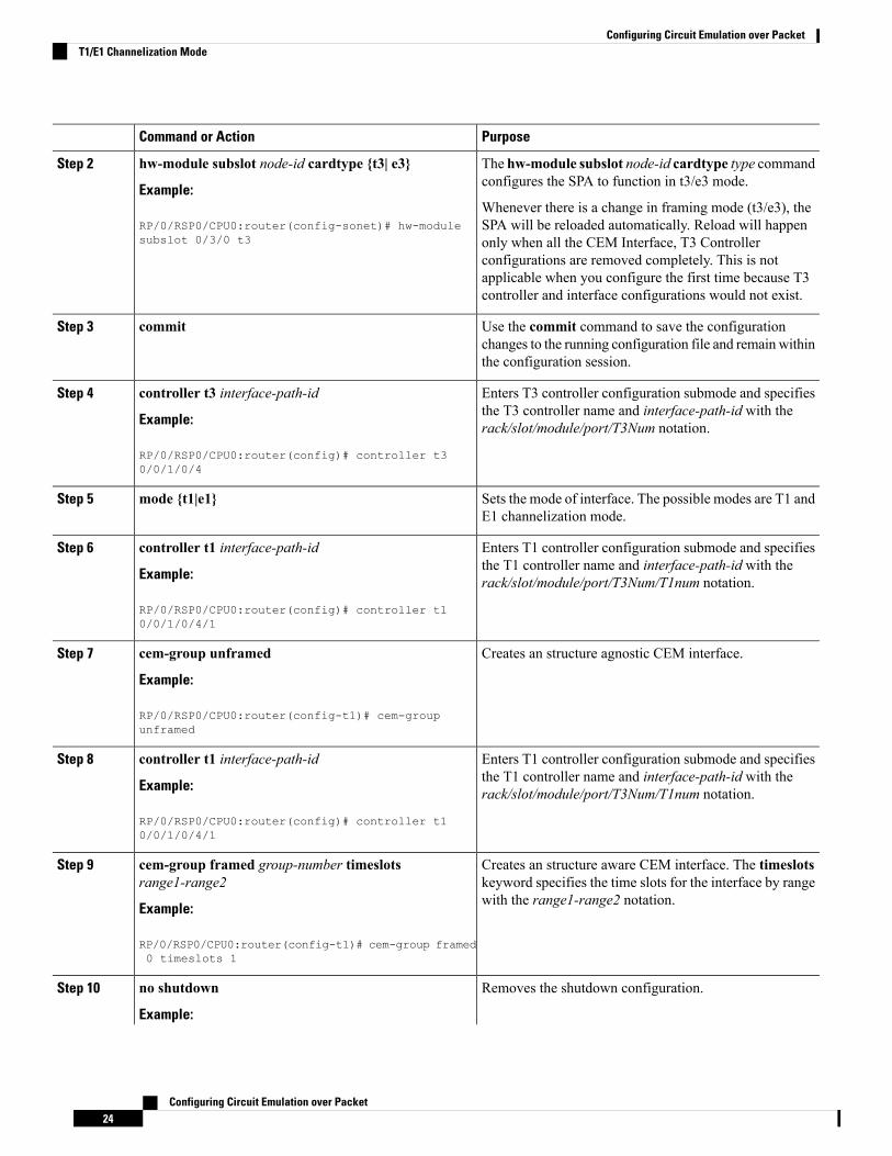
The hw-module subslot node-id cardtype type commandconfigures the SPA to function in t3/e3 mode.
hw-module subslot node-id cardtype {t3| e3}
Example:
Step 2
Whenever there is a change in framing mode (t3/e3), theSPA will be reloaded automatically. Reload will happenRP/0/RSP0/CPU0:router(config-sonet)# hw-module
subslot 0/3/0 t3 only when all the CEM Interface, T3 Controllerconfigurations are removed completely. This is notapplicable when you configure the first time because T3controller and interface configurations would not exist.
Use the commit command to save the configurationchanges to the running configuration file and remain withinthe configuration session.
commitStep 3
Enters T3 controller configuration submode and specifiesthe T3 controller name and interface-path-id with therack/slot/module/port/T3Num notation.
controller t3 interface-path-id
Example:
RP/0/RSP0/CPU0:router(config)# controller t30/0/1/0/4
Step 4
Sets the mode of interface. The possible modes are T1 andE1 channelization mode.
mode {t1|e1}Step 5
Enters T1 controller configuration submode and specifiesthe T1 controller name and interface-path-id with therack/slot/module/port/T3Num/T1num notation.
controller t1 interface-path-id
Example:
RP/0/RSP0/CPU0:router(config)# controller t10/0/1/0/4/1
Step 6
Creates an structure agnostic CEM interface.cem-group unframed
Example:
Step 7
RP/0/RSP0/CPU0:router(config-t1)# cem-groupunframed
Enters T1 controller configuration submode and specifiesthe T1 controller name and interface-path-id with therack/slot/module/port/T3Num/T1num notation.
controller t1 interface-path-id
Example:
RP/0/RSP0/CPU0:router(config)# controller t10/0/1/0/4/1
Step 8
Creates an structure aware CEM interface. The timeslotskeyword specifies the time slots for the interface by rangewith the range1-range2 notation.
cem-group framed group-number timeslotsrange1-range2
Example:
Step 9
RP/0/RSP0/CPU0:router(config-t1)# cem-group framed0 timeslots 1
Removes the shutdown configuration.no shutdownStep 10
Example:
Configuring Circuit Emulation over Packet24
Configuring Circuit Emulation over PacketT1/E1 Channelization Mode
PurposeCommand or Action
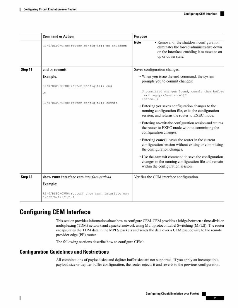
RP/0/RSP0/CPU0:router(config-if)# no shutdown• Removal of the shutdown configurationeliminates the forced administrative downon the interface, enabling it to move to anup or down state.
Note
Saves configuration changes.end or commitStep 11
Example: • When you issue the end command, the systemprompts you to commit changes:
RP/0/RSP0/CPU0:router(config-t1)# end
Uncommitted changes found, commit them beforeorexiting(yes/no/cancel)?[cancel]:
RP/0/RSP0/CPU0:router(config-t1)# commit• Entering yes saves configuration changes to therunning configuration file, exits the configurationsession, and returns the router to EXEC mode.
• Entering no exits the configuration session and returnsthe router to EXEC mode without committing theconfiguration changes.
• Entering cancel leaves the router in the currentconfiguration session without exiting or committingthe configuration changes.
• Use the commit command to save the configurationchanges to the running configuration file and remainwithin the configuration session.
Verifies the CEM interface configuration.show runn interface cem interface-path-id
Example:
Step 12
RP/0/RSP0/CPU0:router# show runn interface cem0/0/2/0/1/1/1/1:1
Configuring CEM InterfaceThis section provides information about how to configure CEM. CEMprovides a bridge between a time-divisionmultiplexing (TDM) network and a packet network using Multiprotocol Label Switching (MPLS). The routerencapsulates the TDM data in the MPLS packets and sends the data over a CEM pseudowire to the remoteprovider edge (PE) router.
The following sections describe how to configure CEM:
Configuration Guidelines and RestrictionsAll combinations of payload size and dejitter buffer size are not supported. If you apply an incompatiblepayload size or dejitter buffer configuration, the router rejects it and reverts to the previous configuration.
Configuring Circuit Emulation over Packet25
Configuring Circuit Emulation over PacketConfiguring CEM Interface

Configuring a Global CEM ClassThis task explains how to configure a global CEM class.
Any interface configuration would have higher precedence over configuration applied through attaching aCEM class. Also, CEM class attached to an interface would have higher precedence than CEM class attachedto the parent controller. For example, if the dummy pattern value of 0xcf is applied directly to an interfaceand then a CEM class which contains dummy pattern value of 0xaa is attached to the same interface, then thedummy pattern value would be 0xcf. The new configuration would not be applied until the dummy patternvalue applied directly to the interface is removed.
Note
SUMMARY STEPS
1. configure2. cem class class-name3. payload value4. dejitter value5. idle pattern value6. dummy mode7. dummy pattern value8. end or commit
DETAILED STEPS
PurposeCommand or Action
Enters global configuration mode.configure
Example:
Step 1
RP/0/RSP0/CPU0:router# configure
Creates a new CEM class.cem class class-name
Example:
Step 2
RP/0/RSP0/CPU0:router(config)# cem class Default
Enter the payload size for the CEM class.payload value
Example:
Step 3
RP/0/RSP0/CPU0:router(config-cem-class)# payload512
Enter the dejitter buffer size for the CEM class.dejitter value
Example:
Step 4
RP/0/RSP0/CPU0:router(config-cem-class)# dejitter10
Configuring Circuit Emulation over Packet26
Configuring Circuit Emulation over PacketConfiguring a Global CEM Class
PurposeCommand or Action
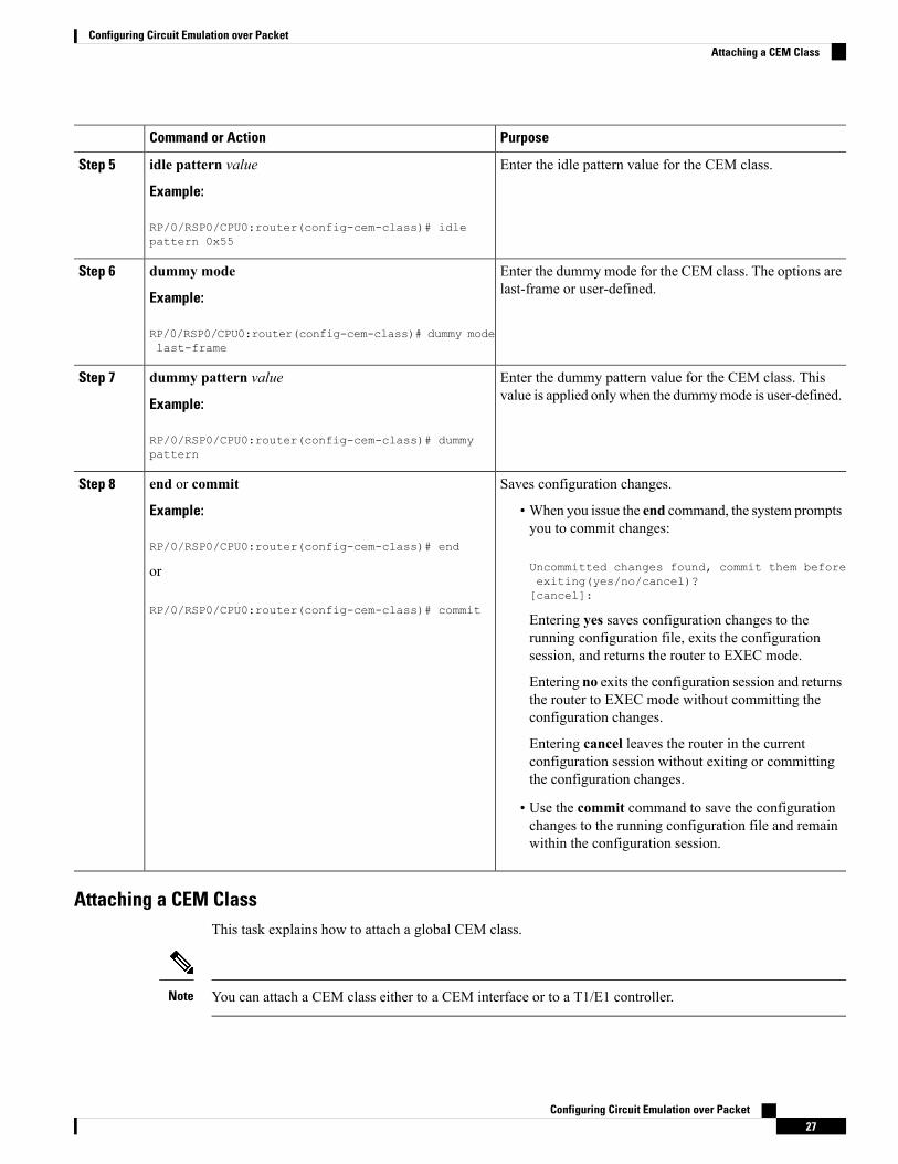
Enter the idle pattern value for the CEM class.idle pattern value
Example:
Step 5
RP/0/RSP0/CPU0:router(config-cem-class)# idlepattern 0x55
Enter the dummy mode for the CEM class. The options arelast-frame or user-defined.
dummy mode
Example:
Step 6
RP/0/RSP0/CPU0:router(config-cem-class)# dummy modelast-frame
Enter the dummy pattern value for the CEM class. Thisvalue is applied only when the dummymode is user-defined.
dummy pattern value
Example:
Step 7
RP/0/RSP0/CPU0:router(config-cem-class)# dummypattern
Saves configuration changes.end or commitStep 8
Example: • When you issue the end command, the system promptsyou to commit changes:
RP/0/RSP0/CPU0:router(config-cem-class)# end
Uncommitted changes found, commit them beforeorexiting(yes/no/cancel)?[cancel]:
RP/0/RSP0/CPU0:router(config-cem-class)# commitEntering yes saves configuration changes to therunning configuration file, exits the configurationsession, and returns the router to EXEC mode.
Entering no exits the configuration session and returnsthe router to EXEC mode without committing theconfiguration changes.
Entering cancel leaves the router in the currentconfiguration session without exiting or committingthe configuration changes.
• Use the commit command to save the configurationchanges to the running configuration file and remainwithin the configuration session.
Attaching a CEM ClassThis task explains how to attach a global CEM class.
You can attach a CEM class either to a CEM interface or to a T1/E1 controller.Note
Configuring Circuit Emulation over Packet27
Configuring Circuit Emulation over PacketAttaching a CEM Class

SUMMARY STEPS
1. configure2. interface cem interface-path-id3. (or)4. controller {t1|e1} interface-path-id5. cem class-attach class-name6. end or commit
DETAILED STEPS
PurposeCommand or Action
Enters global configuration mode.configure
Example:
Step 1
RP/0/RSP0/CPU0:router# configure
interface cem interface-path-idStep 2
(or)Step 3
Specifies the CEM interface or the T1/E1 controller.controller {t1|e1} interface-path-id
Example:
Step 4
RP/0/RSP0/CPU0:router(config)# controller t10/0/2/0/1/1
Attaches the CEM class to an interface or controller.cem class-attach class-name
Example:
Step 5
RP/0/RSP0/CPU0:router(config)# cem class-attachDefault
Saves configuration changes.end or commitStep 6
Example: • When you issue the end command, the system promptsyou to commit changes:
RP/0/RSP0/CPU0:router(config-cem-class)# end
Uncommitted changes found, commit them beforeorexiting(yes/no/cancel)?[cancel]:
RP/0/RSP0/CPU0:router(config-cem-class)# commit• Entering yes saves configuration changes to therunning configuration file, exits the configurationsession, and returns the router to EXEC mode.
• Entering no exits the configuration session and returnsthe router to EXEC mode without committing theconfiguration changes.
• Entering cancel leaves the router in the currentconfiguration session without exiting or committingthe configuration changes.
Configuring Circuit Emulation over Packet28
Configuring Circuit Emulation over PacketAttaching a CEM Class
PurposeCommand or Action
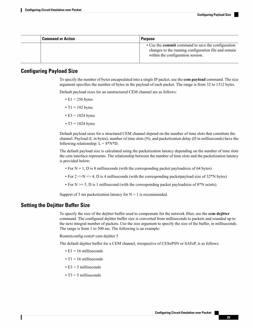
• Use the commit command to save the configurationchanges to the running configuration file and remainwithin the configuration session.
Configuring Payload SizeTo specify the number of bytes encapsulated into a single IP packet, use the cem payload command. The sizeargument specifies the number of bytes in the payload of each packet. The range is from 32 to 1312 bytes.
Default payload sizes for an unstructured CEM channel are as follows:
• E1 = 256 bytes
• T1 = 192 bytes
• E3 = 1024 bytes
• T3 = 1024 bytes
Default payload sizes for a structured CEM channel depend on the number of time slots that constitute thechannel. Payload (L in bytes), number of time slots (N), and packetization delay (D in milliseconds) have thefollowing relationship: L = 8*N*D.
The default payload size is calculated using the packetization latency depending on the number of time slotsthe cem interface represents. The relationship between the number of time slots and the packetization latencyis provided below:
• For N = 1, D is 8 milliseconds (with the corresponding packet payloadsize of 64 bytes)
• For 2 <=N <= 4, D is 4 milliseconds (with the corresponding packetpayload size of 32*N bytes)
• For N >= 5, D is 1 millisecond (with the corresponding packet payloadsize of 8*N octets).
Support of 5 ms packetization latency for N = 1 is recommended.
Setting the Dejitter Buffer SizeTo specify the size of the dejitter buffer used to compensate for the network filter, use the cem dejittercommand. The configured dejitter buffer size is converted from milliseconds to packets and rounded up tothe next integral number of packets. Use the size argument to specify the size of the buffer, in milliseconds.The range is from 1 to 500 ms. The following is an example:
Router(config-cem)# cem dejitter 5
The default dejitter buffer for a CEM channel, irrespective of CESoPSN or SAToP, is as follows:
• E1 = 16 milliseconds
• T1 = 16 milliseconds
• E3 = 5 milliseconds
• T3 = 5 milliseconds
Configuring Circuit Emulation over Packet29
Configuring Circuit Emulation over PacketConfiguring Payload Size
Refer the T1/E1 SAToP lines:Payload and jitter limits table, the T3/E3 SAToP lines:Payload and jitter limitstable, and the ICESoPSN DSo lines:Payload and jitter limits table for the relationship between payload anddejitter buffer on SAToP T1/E1, T3/E3, and CESoPSN lines. Configuration of payload and dejitter shouldbe in accordance with the minimum and maximum values as mentioned in the table.
The maximum and minimum dejitter buffer value, that is the range is fixed for a given payload value.
Note
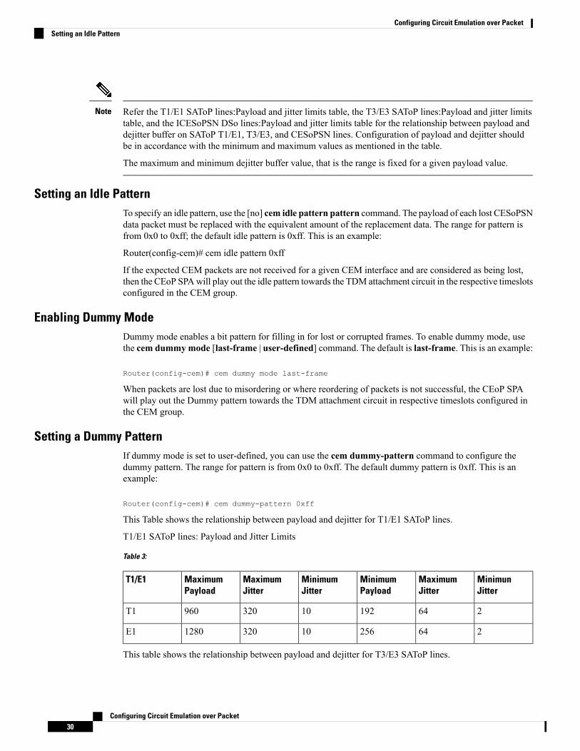
Setting an Idle PatternTo specify an idle pattern, use the [no] cem idle pattern pattern command. The payload of each lost CESoPSNdata packet must be replaced with the equivalent amount of the replacement data. The range for pattern isfrom 0x0 to 0xff; the default idle pattern is 0xff. This is an example:
Router(config-cem)# cem idle pattern 0xff
If the expected CEM packets are not received for a given CEM interface and are considered as being lost,then the CEoP SPAwill play out the idle pattern towards the TDM attachment circuit in the respective timeslotsconfigured in the CEM group.
Enabling Dummy ModeDummy mode enables a bit pattern for filling in for lost or corrupted frames. To enable dummy mode, usethe cem dummymode [last-frame | user-defined] command. The default is last-frame. This is an example:
Router(config-cem)# cem dummy mode last-frame
When packets are lost due to misordering or where reordering of packets is not successful, the CEoP SPAwill play out the Dummy pattern towards the TDM attachment circuit in respective timeslots configured inthe CEM group.
Setting a Dummy PatternIf dummy mode is set to user-defined, you can use the cem dummy-pattern command to configure thedummy pattern. The range for pattern is from 0x0 to 0xff. The default dummy pattern is 0xff. This is anexample:
Router(config-cem)# cem dummy-pattern 0xff
This Table shows the relationship between payload and dejitter for T1/E1 SAToP lines.
T1/E1 SAToP lines: Payload and Jitter Limits
Table 3:
MinimunJitter
MaximumJitter
MinimumPayload
MinimumJitter
MaximumJitter
MaximumPayload
T1/E1
26419210320960T1
264256103201280E1
This table shows the relationship between payload and dejitter for T3/E3 SAToP lines.
Configuring Circuit Emulation over Packet30
Configuring Circuit Emulation over PacketSetting an Idle Pattern

T3/E3 SAToP lines: Payload and Jitter Limits
Table 4:
MinimunJitter
MaximumJitter
MinimumPayload
MinimumJitter
MaximumJitter
MaximumPayload
T3/E3
28672281312T3
285122161312E3
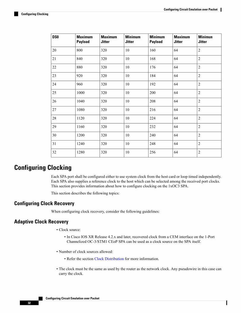
This table shows the relationship between payload and dejitter for DS0 lines.
CESoPSN DS0 Lines: Payload and Jitter Limits
Table 5:
MinimunJitter
MaximumJitter
MinimumPayload
MinimumJitter
MaximumJitter
MaximumPayload
DS0
82563210320401
41283210320802
412833103201203
26432103201604
26440103202005
26448103202406
26456103202807
26464103203208
26472103203609
264801032040010
264881032044011
264961032048012
2641041032052013
2641121032056014
2641201032060015
2641281032064016
2641361032068017
2641441032072018
2641521032076019
Configuring Circuit Emulation over Packet31
Configuring Circuit Emulation over PacketSetting a Dummy Pattern
MinimunJitter
MaximumJitter
MinimumPayload
MinimumJitter
MaximumJitter
MaximumPayload
DS0
2641601032080020
2641681032084021
2641761032088022
2641841032092023
2641921032096024
26420010320100025
26420810320104026
26421610320108027
26422410320112028
26423210320116029
26424010320120030
26424810320124031
26425610320128032
Configuring ClockingEach SPA port shall be configured either to use system clock from the host card or loop timed independently.Each SPA also supplies a reference clock to the host which can be selected among the received port clocks.This section provides information about how to configure clocking on the 1xOC3 SPA.
This section describes the following topics:
Configuring Clock RecoveryWhen configuring clock recovery, consider the following guidelines:
Adaptive Clock Recovery• Clock source:
• In Cisco IOS XR Release 4.2.x and later, recovered clock from a CEM interface on the 1-PortChannelized OC-3/STM1 CEoP SPA can be used as a clock source on the SPA itself.
• Number of clock sources allowed:
• Refer the section Clock Distribution for more information.
• The clock must be the same as used by the router as the network clock. Any pseudowire in this case cancarry the clock.
Configuring Circuit Emulation over Packet32
Configuring Circuit Emulation over PacketConfiguring Clocking
• The minimum bundle size of CEM pseudowires on the network that delivers robust clock recovery is 4DS0s.
• The minimum packet size of CEM pseudowires on the network that delivers robust clock recovery is 64bytes.
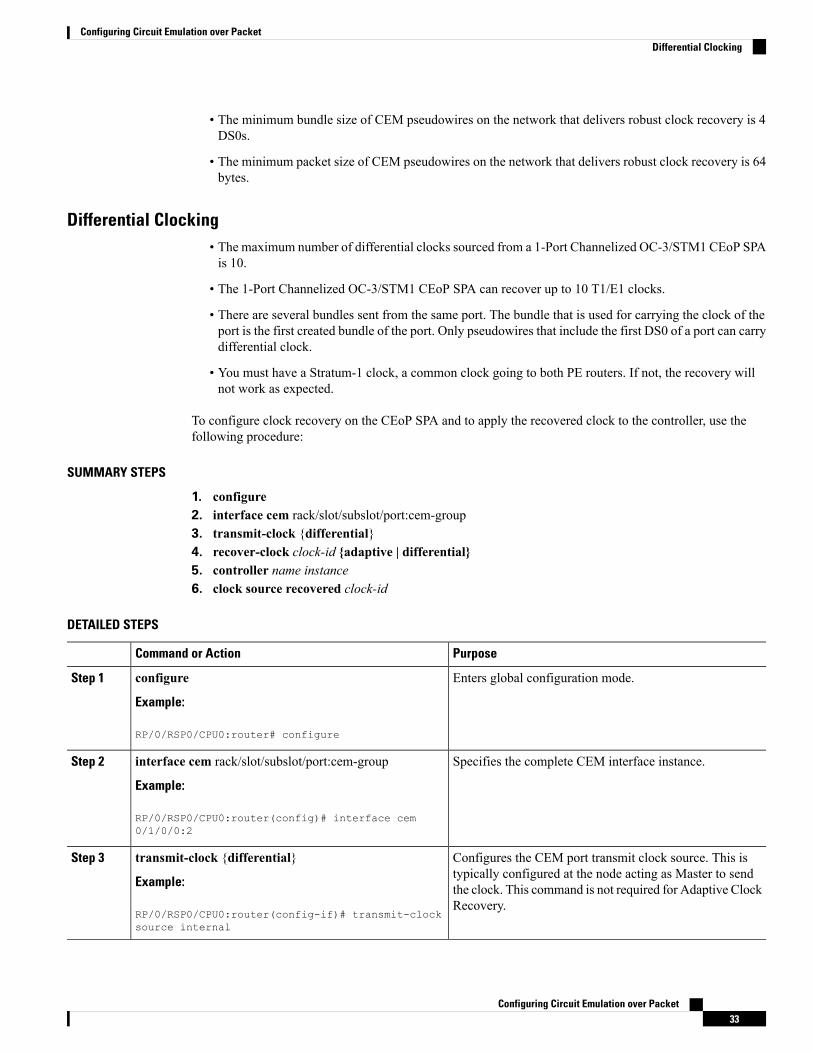
Differential Clocking• The maximum number of differential clocks sourced from a 1-Port Channelized OC-3/STM1 CEoP SPAis 10.
• The 1-Port Channelized OC-3/STM1 CEoP SPA can recover up to 10 T1/E1 clocks.
• There are several bundles sent from the same port. The bundle that is used for carrying the clock of theport is the first created bundle of the port. Only pseudowires that include the first DS0 of a port can carrydifferential clock.
• You must have a Stratum-1 clock, a common clock going to both PE routers. If not, the recovery willnot work as expected.
To configure clock recovery on the CEoP SPA and to apply the recovered clock to the controller, use thefollowing procedure:
SUMMARY STEPS
1. configure2. interface cem rack/slot/subslot/port:cem-group3. transmit-clock {differential}4. recover-clock clock-id {adaptive | differential}5. controller name instance6. clock source recovered clock-id
DETAILED STEPS
PurposeCommand or Action
Enters global configuration mode.configure
Example:
Step 1
RP/0/RSP0/CPU0:router# configure
Specifies the complete CEM interface instance.interface cem rack/slot/subslot/port:cem-group
Example:
Step 2
RP/0/RSP0/CPU0:router(config)# interface cem0/1/0/0:2
Configures the CEM port transmit clock source. This istypically configured at the node acting as Master to send
transmit-clock {differential}
Example:
Step 3
the clock. This command is not required for Adaptive ClockRecovery.
RP/0/RSP0/CPU0:router(config-if)# transmit-clocksource internal
Configuring Circuit Emulation over Packet33
Configuring Circuit Emulation over PacketDifferential Clocking

PurposeCommand or Action
Specifies the recovered clock number and the clock recoverytype. This is typically configured at the node acting as Slave
recover-clock clock-id {adaptive | differential}
Example:
Step 4
that recovers the clock from incoming CEM packets fromcore.
RP/0/RSP0/CPU0:router(config-if)# recover-clockclock-id <> adaptive
Enters controller configuration submode and specifies thecontroller name and instance identifier with therack/slot/module/port/name/instance1/instance2 notation.
controller name instance
Example:
RP/0/RSP0/CPU0:router(config)# controller t10/1/1/0/0/0
Step 5
Specifies the recovered clock number. This applies therecovered clock from a CEM interface on a T1/E1Controller.
clock source recovered clock-id
Example:
RP/0/RSP0/CPU0:router(config-t1)# clock sourcerecovered 3
Step 6
Verifying Clock recoveryTo verify clock recovery, use the show recovered-clock command.
Router# show recovered-clock sublsot 0/3/0Recovered clock status for subslot 0/3/0----------------------------------------Clock Mode Port CEM Status Frequency Offset(ppb)1 ADAPTIVE 0 1 HOLDOVER 0Router# show recovered-clockRecovered clock status for subslot 3/0----------------------------------------Clock Mode Port CEM Status Frequency Offset(ppb)1 ADAPTIVE 0 1 ACQUIRING -694
Show Commands for CEMYou can use the command show controller cem <forward interface instance> to verify the CEM parameterinformation. The following example provides a sample output for the command.
Ouput of show controller cem forward interface instance command
RP/0/RSP0/CPU0:Router# show controllers cem 0/4/1/0:0
Interface : CEM0/4/1/0:0Admin state : UpDriver link state : UpPort bandwidth(kbps) : 1984Dejitter buffer : 16Payload size : 248Dummy mode : last-frameDummy pattern : 0xffIdle pattern : 0xffSignalling : No CAS
Configuring Circuit Emulation over Packet34
Configuring Circuit Emulation over PacketVerifying Clock recovery
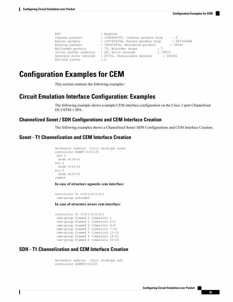
RTP : EnabledIngress packets : 1638960097, Ingress packets drop : 0Egress packets : 1207954294, Egress packets drop : 287140468Missing packets : 160475876, Reordered packets : 50092Malformed packets : 73, Misorder drops : 7Jitter buffer underrun : 28, Error seconds : 79673Severely error seconds : 25721, Unavailable seconds : 160361Failure counts : 2
Configuration Examples for CEMThis section contains the following examples:
Circuit Emulation Interface Configuration: ExamplesThe following example shows a sample CEM interface configuration on the Cisco 1-port ChannelizedOC3/STM-1 SPA.
Channelized Sonet / SDH Configurations and CEM Interface CreationThe following examples shows a Channelized Sonet/ SDH Configurations and CEM Interface Creation.
Sonet - T1 Channelization and CEM Interface Creation
hw-module subslot <loc> cardtype sonetcontroller SONET 0/0/1/0sts 1mode vt15-t1
sts 2mode vt15-t1
sts 3mode vt15-t1
commit
In case of structure agnostic cem interface:
controller T1 0/0/1/0/1/4/1cem-group unframed
In case of structure aware cem interface:
controller T1 0/0/1/0/1/5/1cem-group framed 0 timeslots 1cem-group framed 1 timeslots 2-3cem-group framed 2 timeslots 4-6cem-group framed 3 timeslots 7-10cem-group framed 4 timeslots 11-15cem-group framed 5 timeslots 16-21cem-group framed 6 timeslots 22-24
SDH - T1 Channelization and CEM Interface Creation
hw-module subslot <loc> cardtype sdhcontroller SONET0/0/2/0
Configuring Circuit Emulation over Packet35
Configuring Circuit Emulation over PacketConfiguration Examples for CEM

au 1mode c11-t1au 2mode c11-t1au 3mode c11-t1
commit
In case of structure agnostic cem interface:
controller T1 0/0/2/0/1/1/4cem-group unframed
In case of structure aware cem interface:
controller T1 0/0/2/0/1/7/1cem-group framed 0 timeslots 1cem-group framed 1 timeslots 2-3cem-group framed 2 timeslots 4-6cem-group framed 3 timeslots 7-10cem-group framed 4 timeslots 11-15cem-group framed 5 timeslots 16-21cem-group framed 6 timeslots 22-24
SDH - E1 Channelization and CEM Interface Creation
hw-module subslot <loc> cardtype sdhcontroller SONET 0/0/2/0au 1mode tug3width 3tug3 1mode c12-e1
tug3 2mode c12-e1
tug3 3mode c12-e1
commit
In case of structure agnostic cem interface:
controller E1 0/0/2/0/1/1/1/1cem-group unframed
In case of structure aware cem interface:
controller E1 0/0/2/0/1/1/7/1cem-group framed 0 timeslots 1cem-group framed 1 timeslots 2-3cem-group framed 2 timeslots 4-6cem-group framed 3 timeslots 7-10cem-group framed 4 timeslots 11-15cem-group framed 5 timeslots 16-21cem-group framed 6 timeslots 22-31
CEM Interface Configuration
RP/0/RSP0/CPU0:CEOP-01#show runn interface cem 0/0/2/0/1/1/1/1:1
interface CEM0/0/2/0/1/1/1/1:1
Configuring Circuit Emulation over Packet36
Configuring Circuit Emulation over PacketSDH - E1 Channelization and CEM Interface Creation

l2transport!CEM Interface Config Options :
RP/0/RSP0/CPU0:CEOP-01(config)#interface cem 0/0/2/0/1/1/1/1:1RP/0/RSP0/CPU0:CEOP-01(config-if)#cem ?class-attach Attach a CEM class to this interfaceclock Configure clocks on this CEM interfacedejitter Configure dejitter bufferdummy Configure dummy frame parametersidle Configure idle frame parameterspayload Configure payload size of CEM frames
SAToP CEM interface creation on T3 / E3 on Cisco 2-Port Channelized T3/E3 Circuit Emulation andChannelized ATM SPA
RP/0/0/CPU0:router(config)#controller t3 0/4/2/0RP/0/0/CPU0:router(config-t3)#cem-group ?unframed clear channel carrying CEM
RP/0/0/CPU0:router(config-t3)#cem-group unframedRP/0/0/CPU0:router(config-t3)#commitRP/0/0/CPU0:router(config-t3)#
SAToP CEM interface creation on T1 / E1 on Cisco 2-Port Channelized T3/E3 Circuit Emulation andChannelized ATM SPA
RP/0/0/CPU0:router(config)#controller t3 0/4/2/0RP/0/0/CPU0:router(config-t3)#mode ?atm clear channel carrying atme1 channelize into 21 E1sserial clear channel carrying hdlc like payloadt1 channelized into 28 T1s
RP/0/0/CPU0:router(config-t3)#mode e1RP/0/0/CPU0:router(config-t3)#commit
RP/0/0/CPU0:router(config)#controller e1 0/4/2/0/1RP/0/0/CPU0:router(config-e1)#cem-group ?framed Configure a framed CEM interface on T1/E1unframed Configure a unframed CEM interface on T1/E1
RP/0/0/CPU0:router(config-e1)#cem-group unframed ?<cr>
RP/0/0/CPU0:router(config-e1)#cem-group unframedRP/0/0/CPU0:router(config-e1)#commit
CESoPSN CEM interface creation on T1/E1 on Cisco 2-Port Channelized T3/E3 Circuit Emulationand Channelized ATM SPA
RP/0/0/CPU0:router(config)#controller t3 0/4/2/1RP/0/0/CPU0:router(config-t3)#mode ?atm clear channel carrying atme1 channelize into 21 E1sserial clear channel carrying hdlc like payloadt1 channelized into 28 T1s
RP/0/0/CPU0:router(config-t3)#mode t1RP/0/0/CPU0:router(config-t3)#commit
RP/0/0/CPU0:router(config)#controller t1 0/4/2/1/1RP/0/0/CPU0:router(config-t1)#cem-group ?
Configuring Circuit Emulation over Packet37
Configuring Circuit Emulation over PacketSAToP CEM interface creation on T3 / E3 on Cisco 2-Port Channelized T3/E3 Circuit Emulation and Channelized ATM SPA
framed Configure a framed CEM interface on T1/E1unframed Configure a unframed CEM interface on T1/E1
RP/0/0/CPU0:router(config-t1)#cem-group framed ?<0-23> CEM group number
RP/0/0/CPU0:router(config-t1)#cem-group framed 0 ?timeslots List of timeslots in the CEM group
RP/0/0/CPU0:router(config-t1)#cem-group framed 0 timeslots ?WORD timeslot string seprated by (:) or (-) from 1 to 24. (:) indicates individual
timeslot and (-) represent rangeRP/0/0/CPU0:router(config-t1)#cem-group framed 0 timeslots 1:23RP/0/0/CPU0:router(config-t1)#commit
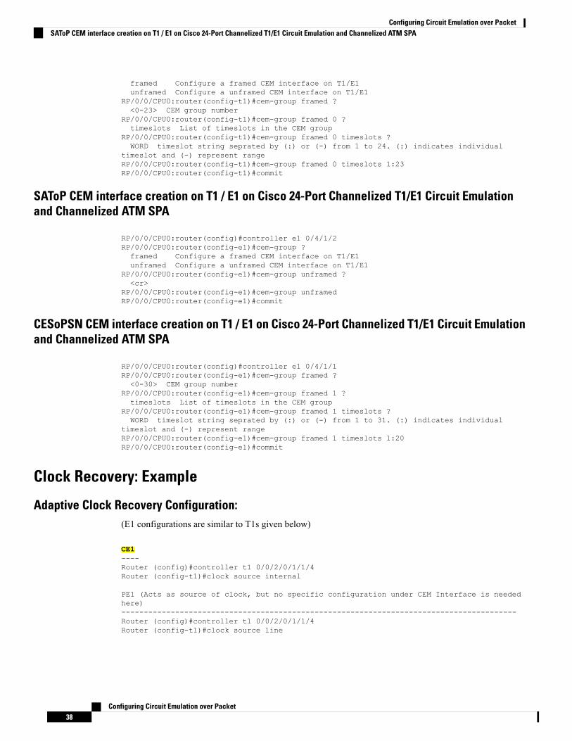
SAToP CEM interface creation on T1 / E1 on Cisco 24-Port Channelized T1/E1 Circuit Emulationand Channelized ATM SPA
RP/0/0/CPU0:router(config)#controller e1 0/4/1/2RP/0/0/CPU0:router(config-e1)#cem-group ?framed Configure a framed CEM interface on T1/E1unframed Configure a unframed CEM interface on T1/E1
RP/0/0/CPU0:router(config-e1)#cem-group unframed ?<cr>
RP/0/0/CPU0:router(config-e1)#cem-group unframedRP/0/0/CPU0:router(config-e1)#commit
CESoPSN CEM interface creation on T1 / E1 on Cisco 24-Port Channelized T1/E1 Circuit Emulationand Channelized ATM SPA
RP/0/0/CPU0:router(config)#controller e1 0/4/1/1RP/0/0/CPU0:router(config-e1)#cem-group framed ?<0-30> CEM group number
RP/0/0/CPU0:router(config-e1)#cem-group framed 1 ?timeslots List of timeslots in the CEM group
RP/0/0/CPU0:router(config-e1)#cem-group framed 1 timeslots ?WORD timeslot string seprated by (:) or (-) from 1 to 31. (:) indicates individual
timeslot and (-) represent rangeRP/0/0/CPU0:router(config-e1)#cem-group framed 1 timeslots 1:20RP/0/0/CPU0:router(config-e1)#commit
Clock Recovery: Example
Adaptive Clock Recovery Configuration:(E1 configurations are similar to T1s given below)
CE1----Router (config)#controller t1 0/0/2/0/1/1/4Router (config-t1)#clock source internal
PE1 (Acts as source of clock, but no specific configuration under CEM Interface is neededhere)----------------------------------------------------------------------------------------Router (config)#controller t1 0/0/2/0/1/1/4Router (config-t1)#clock source line
Configuring Circuit Emulation over Packet38
Configuring Circuit Emulation over PacketSAToP CEM interface creation on T1 / E1 on Cisco 24-Port Channelized T1/E1 Circuit Emulation and Channelized ATM SPA
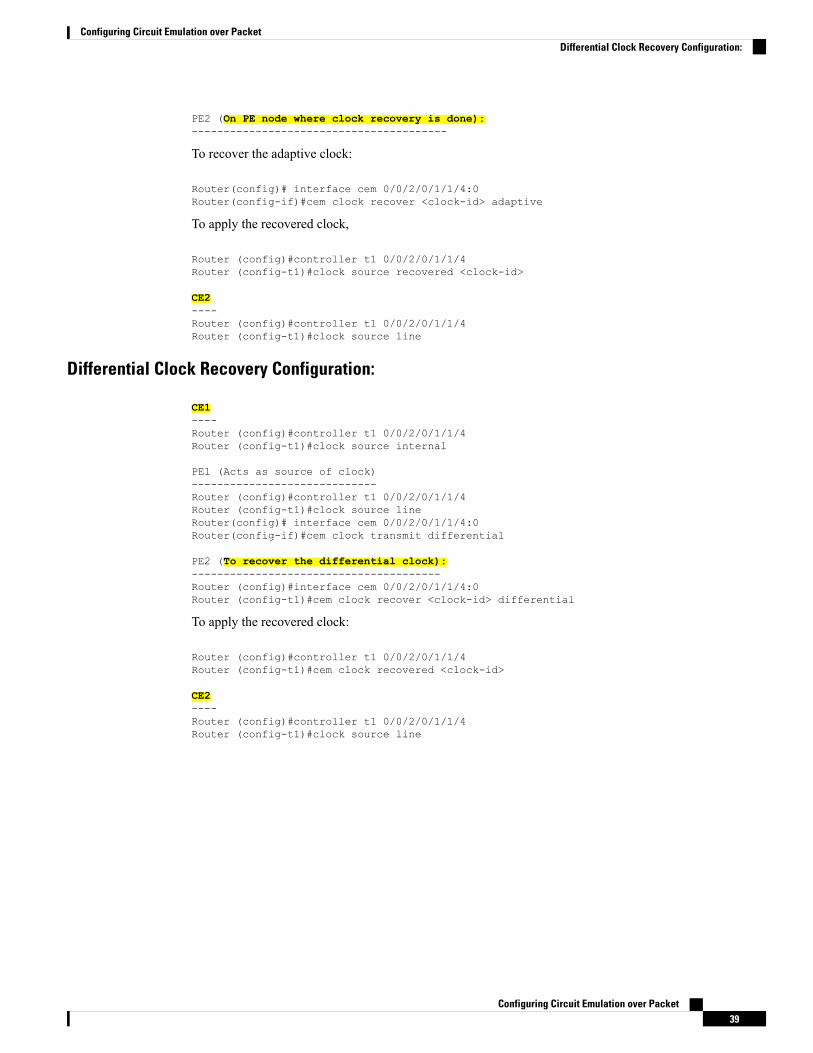
PE2 (On PE node where clock recovery is done):----------------------------------------
To recover the adaptive clock:
Router(config)# interface cem 0/0/2/0/1/1/4:0Router(config-if)#cem clock recover <clock-id> adaptive
To apply the recovered clock,
Router (config)#controller t1 0/0/2/0/1/1/4Router (config-t1)#clock source recovered <clock-id>
CE2----Router (config)#controller t1 0/0/2/0/1/1/4Router (config-t1)#clock source line
Differential Clock Recovery Configuration:
CE1----Router (config)#controller t1 0/0/2/0/1/1/4Router (config-t1)#clock source internal
PE1 (Acts as source of clock)-----------------------------Router (config)#controller t1 0/0/2/0/1/1/4Router (config-t1)#clock source lineRouter(config)# interface cem 0/0/2/0/1/1/4:0Router(config-if)#cem clock transmit differential
PE2 (To recover the differential clock):---------------------------------------Router (config)#interface cem 0/0/2/0/1/1/4:0Router (config-t1)#cem clock recover <clock-id> differential
To apply the recovered clock:
Router (config)#controller t1 0/0/2/0/1/1/4Router (config-t1)#cem clock recovered <clock-id>
CE2----Router (config)#controller t1 0/0/2/0/1/1/4Router (config-t1)#clock source line
Configuring Circuit Emulation over Packet39
Configuring Circuit Emulation over PacketDifferential Clock Recovery Configuration:

Configuring Circuit Emulation over Packet40
Configuring Circuit Emulation over PacketDifferential Clock Recovery Configuration: