connection guide - micro-epsilon
TRANSCRIPT

Connection Guide
IF2030/ENETIP
Interface module

Connection Guide IF2030/ENETIP
2
1 General
This document describes how to connect IF2030/ENETIP with an Allen-Bradley PLC.
IF2030/ENETIP is an interface module to enable integration of Micro-Epsilon sensors
(controller) equipped with either an RS422 or RS485 interface with EtherNet/IP networks,
including Rockwell Automation PLC environments. This guide refers to Studio 5000
Automation Engineering & Design Environment™ (V30.00.00),
mainly Logix Designer®
. Other versions may differ in the design
of the graphical user interface and their range of features.
2 System design
Please prepare the following equipment to connect an IF2030/ENETIP-compatible sensor
(controller) with an Allen-Bradley PLC environment:
Allen-Bradley Logix controller
Micro-Epsilon sensor (controller) with RS422 or RS485 interface, incl. corresponding
connection cable
IF2030/ENETIP interface module, incl. EDS file (download from the Micro-Epsilon
website or data storage device included in the scope of supply)
Computer with installed Rockwell software (Studio 5000)
2x Ethernet cables
Power supply PS2020 (optional)
The ►Operating Instructions contain information on the connectable Micro-Epsilon
sensors (controllers), relevant IF2030/ENETIP interfaces, and details including the
conversion for the output of distance values. The schematic below shows you how to
connect the previously mentioned components in order to project the PLC.

Connection Guide IF2030/ENETIP
3
3 Basic settings and configuration
3.1 Importing IF2030/ENETIP into the software
1. Establish communication with your PLC. Make sure the latter is properly connected to
your computer and running. Launch the Studio 5000 software. Therefore, either double-click
the corresponding Desktop icon or call up the software tool via the Start Menu of your
operating system.
2. Click New Project under the Create section at the top left of the displayed Splash
Screen. The New Project pop-up appears showing a list of possible controllers
(CompactLogix, GuardLogix, ControlLogix etc.). Select the CPU series you are using (in this
example “5069-L306ER”) in this device list. Enter a project name, browse to your desired
project location, and confirm by clicking the Next button.
Note: The specified name also signifies your PLC in the project (cf. labeling of first folder in
the Controller Organizer window).
3. Now you can choose a Revision of firmware and software (if you have multiple
installations). You may also define a Security Authority. Depending on your controller,
there might be further setting options (Chassis Type, Slot, etc.).
Unless otherwise indicated, simply leave everything at the defaults and click the Finish
button. You end up in the main view of Logix Designer®
.

Connection Guide IF2030/ENETIP
4
Note: The Logix Designer®
(previously RSLogix™ 5000) is the first component in the Studio
5000 environment. It is the product used to program Logix controllers for discrete, drive-
based process, batch, axes motion, and safety solutions.
4. To start the import procedure of the IF2030/ENETIP’s EDS file, navigate to Tools in the
Main Menu and click EDS Hardware Installation Tool.
Note: An Electronic Data Sheet (EDS) is an ASCII text file describing the features of the
EtherNet/IP device concerned and is used by software tools for configuration purposes. It
contains, among other things, identity information to allow a tool to recognize a unit.
5. Rockwell Automation’s EDS Wizard is started. Click the Next button and follow the single
steps in the registration dialog. Select the option Register an EDS file(s) and click
the Next button again.
6. Choose Register a single file, click the Browse button, and select the path for
the file ”IF2030ENETIP.eds“ in the open Dialog box. Confirm by clicking the Next button.
The wizard tests the file prior to the installation. Trigger this step by another click on Next.

Connection Guide IF2030/ENETIP
5
7. Now it will be possible to assign images to the nodes, but this is negligible. Click the
Next button to continue and end the installation. The EDS Wizard closes with a click on the
Finish button.
3.2 Configuring the IF2030/ENETIP module
8. After successful registration, IF2030/ENETIP can be
used in the PLC project. Switch to the Controller
Organizer window on the left side of the screen.
Right-click the Ethernet symbol to access a
Shortcut menu and select New Module.
Note: Alternatively you can follow the path File
New Component Module in the Main Menu to
add a new device to the EtherNet/IP network.

Connection Guide IF2030/ENETIP
6
9. The Select Module Type
window is opened. Search for
“IF2030” in the Filter Field
and select the interface module
from the Catalog Number list.
After that, click the Create
button.
Note: Of course you can also
scroll through the entire list or use
filters (via the Show/Hide
Filters button).
If IF2030/ENETIP does not appear in the list of registered devices, either its EDS file is not
registered or the installation failed.
10. When the Module Properties window does not open
automatically, you can do so by right-clicking
IF2030/ENETIP in the Controller Organizer window
and selecting the Properties item or simply double-
clicking the interface module.
Insert a name for the interface module and set its IP address
(cf. ►Section 4). Follow the dialog to complete the device
configuration.
Note: You can click the Change button if there is any
change you would like to make. For general purposes
however, there is no need to change the parameters from
the imported EDS file which can be used directly for
connection.

Connection Guide IF2030/ENETIP
7
11. Save the project. Either use the File menu or the symbol button in the Standard
Toolbar for this purpose.
3.3 Loading the configuration into the PLC
12. The PLC must finally execute the project. First of all, the project has to be downloaded to
your processor. In case you have several units available, extend the drop-down menu with a
click in the Main Menu on Communications and choose Who Active. Pick the processor
that should execute your project in the displayed Who Active window.
Trigger the download process, e.g. via:
Who Active window and Download button
Communications in the Main Menu and
Download item
symbol button in the Online Toolbar and
Download item
You will be asked to verify the download. Click Download to proceed.
Note: Several message boxes may appear depending on your configuration, especially
when the current content of the PLC (program and data) is overwritten. The software guides

Connection Guide IF2030/ENETIP
8
you through the download process. It is therefore important to follow the directions and
prompts. For instance, it might be necessary to switch the PLC’s mode from running to
programming in order to interrupt the current program and overwrite it with a new one.
Online editing and downloads are not possible in the Run mode!
13. After the project is downloaded, it can be placed online and executed in the processor.
The final message you will see is whether you wish to go online. Confirm this by clicking the
Yes button.
The Online state is indicated in green in the Online Toolbar. Now the processor scans
and updates IO according to your project, so that Logix Designer®
displays the CPU’s
program and data information.

Connection Guide IF2030/ENETIP
9
4 IP address / BOOTP default configuration
A BOOTP default configuration is mandatory within a Rockwell PLC network. This means
that your IF2030/ENETIP requires an operational IP address!
There are different ways to define a network IP address. This guide describes the path you
must take using the BOOTP-DHCP Tool (recommendation: from version v3.03.00) which is
part of the Rockwell software package. This standalone server assigns an IP address to
Ethernet devices. Setting additional Transport Control Protocol (TCP) parameters is also
possible.
Note: To operate an EtherNet/IP network, you must define an IP address, subnet mask, and
gateway. However, if you use DNS addressing or refer to the IF2030/ENETIP by a host name
in the message (MSG) commands, you must also define the host and domain name as well
as the addresses of the primary and secondary DNS servers.
1. Ensure that you have the hardware (MAC) address of IF2030/ENETIP. The workstation
that you use to set the IP address should only have one connection to the EtherNet/IP
network on which the interface module resides.
2. Start the BOOTP-DHCP Tool. Most likely you will find it in
the Start Menu under Programs Rockwell
Software BOOTP-DHCP Tool. You may be asked to
select the network interface if you are using several
network cards.
3. If you are using this tool for the first time, you must
specify the network settings. Therefore go to Tools
Network Settings. Enter your network parameters
and confirm with a click on the OK button.
Typical standard parameters are shown in the
screenshot alongside.

Connection Guide IF2030/ENETIP
10
In the background, IF2030/ENETIP will either broadcast its MAC address or a message
requesting the BOOTP or DHCP server to respond with an IP address.
4. The Request History
window is displayed with the
MAC addresses of all devices
that issue BOOTP or DHCP
requests. Select IF2030/ENETIP
and click the Add Relation
button or double-click the
device. The New Entry dialog
box appears.
5. Enter the IP Address. Hostname and Description are optional. Click the OK button
to confirm your data and establish a relation between MAC and IP address.
Hint: You can see whether your assignment was successful in the IP Address column.
6. To assign this configuration on the device, wait for IF2030/ENETIP to appear in the
Relation List panel. The latter happens when the interface card sends its next request,
as the server then responds with the configured IP address.
Now disable the BOOTP utility in IF2030/ENETIP. Select the interface module in the
Relation List panel and click the Disable BOOTP/DHCP button in the middle right of
the dialog box, so that the current IP configuration is not cleared on future power cycles.
This way, a static IP is generated.

Connection Guide IF2030/ENETIP
11
The device now uses the assigned configuration and does not issue BOOTP or DHCP
requests after power is cycled on the controller. Close the dialog box to continue with your
project configuration.

Connection Guide IF2030/ENETIP
12
5 Accessing input and output data
There are multiple different ways to configure the communication between IF2030/ENETIP
and the Allen-Bradley PLCs. This section focusses on the so-called message (MSG)
instructions.
1. Go to the Controller Organizer and double-
click the “MainRoutine“ which is normally found
under Task MainTask MainProgram. This
opens the empty routine in the Main Window.
2. Insert a new rung. Therefore, either
double-click the (End) entry or click /
drag-and-drop the symbol button in
the Language Element Toolbar
grouped under the Bit tab.
Note: The red color of rung 0 and the
circled “x” only indicate that this rung is
still incomplete. The software
automatically verifies your rungs to
support you in programming.
3. Add a new message instruction to the
newly created rung. This language element
is located in the Input/Output group.
Click the symbol button and drag it to
rung 0.
Hint: A green dot indicates the position
where you place your element.

Connection Guide IF2030/ENETIP
13
4. Double-click on the “?” of the new MSG element
that might be highlighted in blue when currently
selected. Type in the desired name (“m1” in our
example).
This results in an undefined tag. To define it, right-
click the tag and select New ‘m1’. The New
Parameter or Tag window appears with the
adopted name “m1” and an already predefined
MESSAGE data type. Click Create to confirm and
store the tag in the local tag database.
Note: Of course, you can right-click the “?” directly and select New Tag. Specify the
attributes for the tag according to your purposes.
5. To configure the message
instruction, click the symbol
button to the right of the tag’s name.
The Message Configuration
window appears.
Select CIP Generic as message
type from the drop-down list. In this
example, data should be read from
IF2030/ENETIP, so choose Get
Attribute Single as service
type.
Note: CIP Generic distinguishes two service codes:
Get Attribute Single reads a specified block of data from IF2030/ENETIP and
places the data in the tag indicated as Destination Element parameter.
Set Attribute Single writes from a tag in the PLC to a block of data in the
interface module. The Source Element parameter indicates which tag to use as
data source. This time, it is necessary to specify the Source Length parameter as
the size in bytes of the data to be transferred.
If not already done in advance, create the “baud” tag. Enter the name for the Destination
Element, click New Tag, and proceed as described in ►Step 4 except with the difference
that DINT should be chosen as data type.
Connection Guide IF2030/ENETIP
14
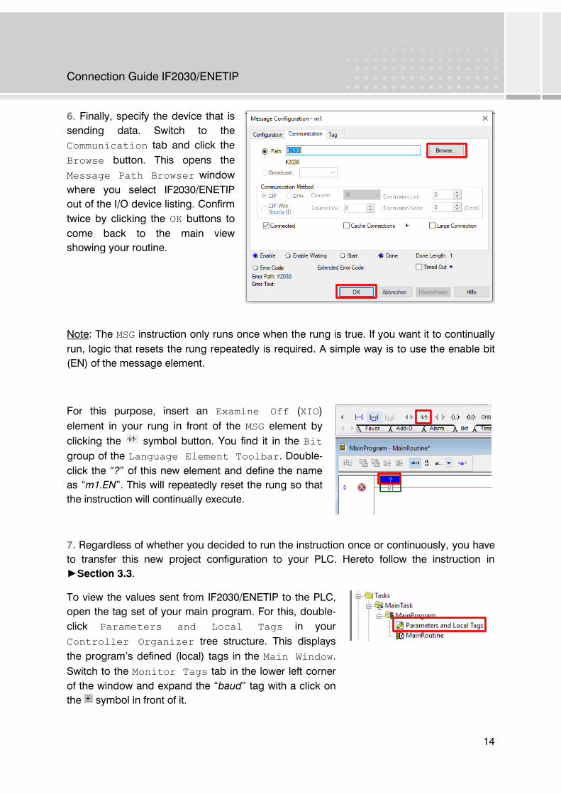
6. Finally, specify the device that is
sending data. Switch to the
Communication tab and click the
Browse button. This opens the
Message Path Browser window
where you select IF2030/ENETIP
out of the I/O device listing. Confirm
twice by clicking the OK buttons to
come back to the main view
showing your routine.
Note: The MSG instruction only runs once when the rung is true. If you want it to continually
run, logic that resets the rung repeatedly is required. A simple way is to use the enable bit
(EN) of the message element.
For this purpose, insert an Examine Off (XIO)
element in your rung in front of the MSG element by
clicking the symbol button. You find it in the Bit
group of the Language Element Toolbar. Double-
click the “?” of this new element and define the name
as “m1.EN”. This will repeatedly reset the rung so that
the instruction will continually execute.
7. Regardless of whether you decided to run the instruction once or continuously, you have
to transfer this new project configuration to your PLC. Hereto follow the instruction in
►Section 3.3.
To view the values sent from IF2030/ENETIP to the PLC,
open the tag set of your main program. For this, double-
click Parameters and Local Tags in your
Controller Organizer tree structure. This displays
the program’s defined (local) tags in the Main Window.
Switch to the Monitor Tags tab in the lower left corner
of the window and expand the “baud” tag with a click on
the symbol in front of it.
Connection Guide IF2030/ENETIP
15
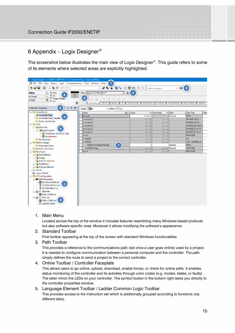
6 Appendix – Logix Designer®
The screenshot below illustrates the main view of Logix Designer®
. This guide refers to some
of its elements where selected areas are explicitly highlighted.
1. Main Menu
Located across the top of the window it includes features resembling many Windows-based products,
but also software-specific ones. Moreover it allows modifying the software’s appearance.
2. Standard Toolbar
First toolbar appearing at the top of the screen with standard Windows functionalities.
3. Path Toolbar
This provides a reference to the communications path (set once a user goes online) used by a project.
It is needed to configure communication between a personal computer and the controller. The path
simply defines the route to send a project to the correct controller.
4. Online Toolbar / Controller Faceplate
This allows users to go online, upload, download, enable forces, or check for online edits. It enables
status monitoring of the controller and its activities through color codes (e.g. modes, states, or faults).
The latter mimic the LEDs on your controller. The symbol button in the bottom right takes you directly to
the controller properties window.
5. Language Element Toolbar / Ladder Common Logic Toolbar
This provides access to the instruction set which is additionally grouped according to functions (via
different tabs).
1
4
6
d
c
a
b
7
2
3
5

Connection Guide IF2030/ENETIP
16
6. Controller Organizer
Organized like Windows Explorer, this graphical representation of the controller file’s contents gives
users access to different sections of a project, especially the tag databases and the programs which are
executed by the controller. A tag, in general, is a name or more precisely a text-based memory address.
Keep in mind that these objects (folders / tree items) change depending on the specific application.
a. Controller with controller-scoped tags
Global variables whose data can be used by every task or program within the controller
application. A double-click on the first folder brings the user to the controller properties.
b. Tasks
Contains tasks (continuous, periodic) the controller will be executing. Each task has one or
more programs (scheduled, unscheduled) and they will include routines containing the
executable code of a program. Most likely, the code is specified in Ladder Logic, but there are
other languages too. In other words: this section contains everything that allows you to run
certain programs.
c. Backplane modules
Whereas the chassis physically holds the modules which allow the system to interface field
devices and connects them, the backplane is the part of the chassis that sends the signals
between the modules. It operates as a mini network, similar to the control bus. The chassis has
slots referring to the available spaces which are labeled starting from 0.
d. Ethernet ports
7. Main Window showing IF2030/ENETIP input data
On the one hand it shows the programming environment for the language being used. So, routines can
be displayed for monitoring or editing. On the other hand (as in the screenshot) the tag database is
shown and can be edited. Take care of the data scope when you are monitoring or editing your tags (cf.
scope attribute at the top left of the window with selection box).

Connection Guide IF2030/ENETIP
17

Preliminary Version | X9751417.01-A012020DWI