operating instructions - micro-epsilon...micro-epsilon messtechnik gmbh & co. kg königbacher...
TRANSCRIPT

Operating Instructions
thicknessSENSOR
10/200 10/400
25/200 25/400

MICRO-EPSILON MESSTECHNIKGmbH & Co. KGKönigbacher Strasse 15
94496 Ortenburg / Germany
Phone +49 (0) 8542 / 168-0 Fax +49 (0) 8542 / 168-90email [email protected]
Sensor for thickness measurement

thicknessSENSOR
Contents
1. Safety ........................................................................................................................................ 51.1 Symbols Used ................................................................................................................................................. 51.2 Warnings .......................................................................................................................................................... 51.3 Notes on CE Marking ...................................................................................................................................... 51.4 Intended Use ................................................................................................................................................... 61.5 Foreseeable Misuse ......................................................................................................................................... 61.6 Proper Environment ......................................................................................................................................... 6
2. Laser Class ............................................................................................................................... 7
3. Functional Principle ................................................................................................................. 83.1 Base Frame ...................................................................................................................................................... 83.2 Sensors ........................................................................................................................................................... 93.3 Calibration Target ............................................................................................................................................. 93.4 Technical Data ............................................................................................................................................... 10
4. Delivery ................................................................................................................................... 114.1 Unpacking /Included in Delivery ................................................................................................................... 114.2 Storage .......................................................................................................................................................... 11
5. Mounting ................................................................................................................................. 125.1 General .......................................................................................................................................................... 125.2 Error Influences ............................................................................................................................................. 12
5.2.1 Ambient Light ............................................................................................................................... 125.2.2 Color Differences ......................................................................................................................... 125.2.3 Surface Roughness ..................................................................................................................... 125.2.4 Temperature Influences ............................................................................................................... 125.2.5 Movement Blurs ........................................................................................................................... 125.2.6 Optimizing the Measuring Accuracy ........................................................................................... 13
5.3 Mechanical Fastening, Dimensional Drawing ............................................................................................... 145.4 Control and Display Elements ....................................................................................................................... 185.5 Electrical Connections ................................................................................................................................... 18
5.5.1 Connection Possibilities ............................................................................................................... 185.5.2 Pin Assignment ............................................................................................................................. 195.5.3 Power Supply ............................................................................................................................... 195.5.4 Current Output .............................................................................................................................. 195.5.5 Voltage Output .............................................................................................................................. 205.5.6 Trigger, Master Function Inputs .................................................................................................... 205.5.7 Switching Outputs ........................................................................................................................ 205.5.8 Connector and Sensor Cable....................................................................................................... 21
6. Operation ................................................................................................................................ 226.1 Getting Ready for Operation ......................................................................................................................... 226.2 Operation Using Ethernet .............................................................................................................................. 22
6.2.1 Requirements ............................................................................................................................... 226.2.2 Access via Ethernet ...................................................................................................................... 236.2.3 Measured Value Display with Web Browser ................................................................................ 25
6.3 Home Menu ................................................................................................................................................... 266.4 Preferences Menu .......................................................................................................................................... 27
6.4.1 Language Selection...................................................................................................................... 276.4.2 Sensors ......................................................................................................................................... 276.4.3 Measuring Rate ............................................................................................................................ 286.4.4 Filter / Averaging / Error Handling Inside thicknessSENSOR ..................................................... 296.4.5 Zeroing / Mastering ...................................................................................................................... 316.4.6 Digital Interfaces ........................................................................................................................... 32
6.4.6.1 Selection of Digital Interfaces ..................................................................................... 326.4.6.2 Data Selection ............................................................................................................. 336.4.6.3 Ethernet Settings ......................................................................................................... 34
6.4.7 Analog Outputs............................................................................................................................. 356.4.7.1 Analog Output 1 and 2 ................................................................................................ 35
6.4.8 Digital Ports .................................................................................................................................. 376.4.8.1 Digital Input ................................................................................................................. 376.4.8.2 Digital Outputs ............................................................................................................. 37
6.4.9 Output Data Rate .......................................................................................................................... 386.4.10 Trigger Mode ................................................................................................................................ 396.4.11 Load/Save Settings ...................................................................................................................... 406.4.12 Manage Settings on PC ............................................................................................................... 416.4.13 Extras ............................................................................................................................................ 43
6.4.13.1 Language .................................................................................................................... 436.4.13.2 Factory Defaults .......................................................................................................... 436.4.13.3 Reset of Controller ...................................................................................................... 44
6.5 Measuring Menu ............................................................................................................................................ 456.6 Help/Info Menu .............................................................................................................................................. 47
7. Software Support with MEDAQLib ........................................................................................ 48
8. Liability for Material Defects .................................................................................................. 49
9. Service, Repair ...................................................................................................................... 49
10. Decommissioning, Disposal .................................................................................................. 49

thicknessSENSOR
Appendix
A 1 Accessories ............................................................................................................................ 50
A 2 Factory Defaults ..................................................................................................................... 51A 2.1 Home ............................................................................................................................................................. 51A 2.2 Sensors .......................................................................................................................................................... 51A 2.3 Measuring Rate .............................................................................................................................................. 51A 2.4 Filter / Averaging / Error Handling inside thicknessSENSOR ....................................................................... 51A 2.5 Zeroing/Mastering.......................................................................................................................................... 51A 2.6 Digital interfaces ............................................................................................................................................ 51A 2.7 Analog Outputs .............................................................................................................................................. 51A 2.8 Digital Ports .................................................................................................................................................... 52A 2.9 Output Data Rate ........................................................................................................................................... 52A 2.10 Trigger Mode .................................................................................................................................................. 52A 2.11 Load/Save Settings ........................................................................................................................................ 52A 2.12 Extras ............................................................................................................................................................. 52
A 3 Pin Assignment ...................................................................................................................... 53
A 4 ASCII Communication with the Sensor ................................................................................. 54A 4.1 General .......................................................................................................................................................... 54A 4.2 Data Protocol ................................................................................................................................................. 54A 4.3 Commands Overview .................................................................................................................................... 57A 4.4 Commands .................................................................................................................................................... 58
A 4.4.1 Controller Information ................................................................................................................... 58A 4.4.2 Search Sensor .............................................................................................................................. 58A 4.4.3 Sensor Information ....................................................................................................................... 58A 4.4.4 Read all Settings ........................................................................................................................... 58A 4.4.5 Language Setting ......................................................................................................................... 58A 4.4.6 Synchronization ............................................................................................................................ 59A 4.4.7 Boot the Controller ....................................................................................................................... 59A 4.4.8 Triggering ...................................................................................................................................... 59
A 4.4.8.1 Trigger SelectionA 4.4.8.2 Trigger LevelA 4.4.8.3 Number of Measured Values to be OutputA 4.4.8.4 Software Trigger Pulse
A 4.4.9 Ethernet ........................................................................................................................................ 60A 4.4.10 Setting the Measured Value Server .............................................................................................. 60A 4.4.11 Transmission Rate ........................................................................................................................ 60A 4.4.12 Save Parameters .......................................................................................................................... 60A 4.4.13 Load Parameters .......................................................................................................................... 60A 4.4.14 Factory defaults ............................................................................................................................ 60A 4.4.15 Measurement Mode ..................................................................................................................... 61A 4.4.16 Measuring Rate ............................................................................................................................ 61A 4.4.17 Measured Value Averaging Controller ......................................................................................... 61A 4.4.18 Measured Value Averaging Sensor .............................................................................................. 61A 4.4.19 Mastering / Zeroing ...................................................................................................................... 61A 4.4.20 Selection Digital Output................................................................................................................ 61A 4.4.21 Output Data Rate .......................................................................................................................... 62A 4.4.22 Scale Output Values ..................................................................................................................... 62A 4.4.23 Error Handling .............................................................................................................................. 62A 4.4.24 Data Selection for USB ................................................................................................................. 62A 4.4.25 Data Selection for Ethernet .......................................................................................................... 63A 4.4.26 Function Selection Multi-function Input........................................................................................ 63A 4.4.27 Activate Error Output, Switching Output 1 ................................................................................... 63A 4.4.28 Activate Error Output, Switching Output 2 ................................................................................... 63A 4.4.29 Limit Values................................................................................................................................... 64A 4.4.30 Data Selection ............................................................................................................................. 64A 4.4.31 Output Area .................................................................................................................................. 64A 4.4.32 Two-point Scaling ......................................................................................................................... 64A 4.4.33 Send Command to Connected Sensor........................................................................................ 65A 4.4.34 Laser off / Laser on ....................................................................................................................... 65A 4.4.35 Find thicknessSENSOR................................................................................................................ 65
A 4.5 Error Values via USB...................................................................................................................................... 65A 4.6 Error Values via Ethernet ............................................................................................................................... 65

Page 5
Safety
thicknessSENSOR
1. SafetyThe handling of the system assumes knowledge of the instruction manual.
1.1 Symbols Used
The following symbols are used in this instruction manual.
Indicates a hazardous situation which results in minor or mode-rate injuries if not avoided.
NOTICE Indicates a situation that may result in property damage if not avoided.
Indicates a user action.
i Indicates a tip for users.Measure Indicates hardware or a software button/menu.
1.2 Warnings
Avoid unnecessary laser radiation to be exposed to the human body.
Switch off the sensor for cleaning and maintenance.
Switch off the sensor for system maintenance and repair if the sensor is integrated into a system.
Caution - use of controls or adjustments or performance of procedures other than those specified may cause harm.
Connect the power supply and the display / output device in accordance with the safety regulations for electrical equipment.
> Risk of injury
> Damage to or destruction of the sensors, the controller
The power supply must not exceed the specified limits. > Risk of injury
> Damage to or destruction of the sensors, the controller
Avoid shocks and impacts to the sensors, the mechanics. > Damage to or destruction of the sensors, the controller
Do not clean the protective glass of the sensors with water. > Damage to the protective glass
1.3 Notes on CE Marking
The following apply to the thicknessSENSOR:
- EU Directive 2014/30/EU,
- EU Directive 2011/65/EU, “RoHS” Category 9
Products which carry the CE mark satisfy the requirements of the EU directives cited and the European harmonized standards (EN) listed therein. The EU Declaration of Conformi-ty is available to the responsible authorities according to EU Directive, article 10, at:
MICRO-EPSILON MESSTECHNIKGmbH & Co. KGKönigbacher Straße 1594496 Ortenburg / Germany
The sensor is designed for use in industrial environments and meets the requirements.
NOTICE

thicknessSENSOR
1.4 Intended Use
- The thicknessSENSOR is designed for use in industrial and laboratory applications. It is used for
� thickness measurement
� quality monitoring and dimensional inspection
� profile measurement
- The sensor must only be operated within the limits specified in the technical data.
- The sensor must be used in such a way that no persons are endangered or machines and other material goods are damaged in the event of malfunction or total failure of the controller.
- Take additional precautions for safety and damage prevention in case of safety-related applications.
1.5 Foreseeable Misuse
If the target/strip material flow has started, the calibration component holder may not be retracted. Collision of the target/strip material with the calibration component holder.
During the reference measurement, the target/strip material flow may not be started. Collision of the target/strip material with the calibration component holder.
1.6 Proper Environment
- Protection class: IP 65
- Operating temperature: 0 ... 50 °C (+32 ... +122 °F) (non-condensing)
- Storage temperature: -20 ... 70 °C (-4 ... +158 °F) (non-condensing)
- Humidity: 5 - 95 % (non-condensing)
- Ambient pressure: Atmospheric pressure
i The protection class is limited to water (no penetrating liquids, detergents or similar aggressive media). Use a protective housing in case of permanent exposure to water.
Optical inputs are excluded from protection class. Contamination leads to impairment or failure of the function.

Page 7
Laser Class
thicknessSENSOR
2. Laser ClassThe sensors of the thicknessSENSOR operate with a semiconductor laser with a wave-length of 670 nm (visible/red).
The sensors fall within Laser Class 2. The lasers are pulsed, the maximum optical power is ≤1 mW. The pulse frequency depends on the set measuring rate (0.25 ... 4 kHz). The pulse duration of the peaks is regulated depending on the measuring rate and the reflec-tivity of the measurement object and can be 0.3 ... 3999.6 μs.
i Observe the laser protection regulations.
When operating the sensors, the relevant regulations in accordance with DIN EN 60825-1 (VDE 0837, Part 1 dated 07/2015) and the accident prevention instructions on laser radiation (BGV B2 dated 01/1997) valid in Germany must be observed. Thereafter:
- With class 2 laser devices, the eye is not endangered by random, brief exposure to laser radiation, i.e. exposure times of up to 0.25 s.
- Class 2 laser devices may therefore be used without further protective measures if you do not intentionally look into the laser beam or in specularly reflected radiation for more than 0.25 s.
- Because the presence of the eyelid protective reflex should not normally be assumed, one should deliberately close the eyes or turn away immediately if the laser beam hits the eye.
Class 2 laser devices are not subject to notification and a laser protection officer is not required.
LASERSTRAHLUNGNICHT IN DEN STRAHL BLICKEN
LASER KLASSE 2nach DIN EN 60825-1: 2015-07
P 1mW; =670nm≤
LASER RADIATIONDO NOT STARE INTO THE BEAM
CLASS 2 LASER PRODUCTIEC 60825-1: 2015-07P 1mW; =670nm≤
THIS PRODUCT COMPLIES WITH FDAREGULATIONS 21CFR 1040.10 AND 1040.11
Fig. 1 Laser warning signsFig. 2 Laser warning symbol
LASERSTRAHLUNGNICHT IN DEN STRAHL BLICKEN
LASER KLASSE 2nach DIN EN 60825-1: 2015-07
P 1mW; =670nm≤
LASER RADIATIONDO NOT STARE INTO THE BEAM
CLASS 2 LASER PRODUCTIEC 60825-1: 2015-07P 1mW; =670nm≤
THIS PRODUCT COMPLIES WITH FDAREGULATIONS 21CFR 1040.10 AND 1040.11
LASERSTRAHLUNGNICHT IN DEN STRAHL BLICKEN
LASER KLASSE 2nach DIN EN 60825-1: 2015-07
P 1mW; =670nm≤
LASER RADIATIONDO NOT STARE INTO THE BEAM
CLASS 2 LASER PRODUCTIEC 60825-1: 2015-07P 1mW; =670nm≤
THIS PRODUCT COMPLIES WITH FDAREGULATIONS 21CFR 1040.10 AND 1040.11
optoNCDT
optoNCDT
Fig. 3 Laser warning signs on the sensor
i If both warning signs are hidden in the installed state, the user must ensure that additional warning signs are fitted at the point of installation.
The operation of the laser is indicated by an LED on the sensor, see Chap. 5.4.
The housing of the laser-optical sensors may only be opened by the manufacturer, see Chap. 8., see Chap. 9.
For repair and service purposes the sensors must always be sent to the manufacturer.
Do not look deliberate-ly into the laser beam. Close your eyes or immediately turn away if the laser beam hits the eye.

Page 8
Functional Principle
thicknessSENSOR
3. Functional Principle
3.1 Base Frame
The sensor is used for the non-contact thickness measurement of non-transparent strips and plates.
Target
Upper beam
Lower beam
Sensor 2
Sensor 1
Fig. 4 Schematic representation of the measuring machine
The measuring method of the unit is based on double-sided thickness measurement, consisting of two laser-optical sensors, which measure the target from opposite posi-tions. The thickness of the target is calculated in the integrated controller.
ControllerSensor 2
Sensor 1
SM
R 2
SM
R 1
Mea
sure
men
tob
ject
Inpu
t 2
Inpu
t 1
Fig. 5 Sensor arrangement for the thickness measurement
The thickness determination does not require any complex target support. The main advantage is that vibrations of the target do not result in inaccurate measurement. The positional tolerance of the target is determined from the working gap, the start of mea-suring range (SMR), see Fig. 5, and the measuring range (MR) of the laser sensors, see Fig. 6.
Wor
king
gap
M
R
Target
Positional tolerancetarget
Wor
king
gap
M
R
Target
Positional tolerancetarget
Wor
king
gap
MR
Target
Positional tolerancetarget
Target in the MR, measurement successful
Target outside of the MR, measurement unsuccessful
Target partly in the MR, measurement unsuccessful
No damage to the target/measuring machineFig. 6 Possible positions of the material to be measured and statements about the feasi-bility of thickness measurement

Page 9
Functional Principle
thicknessSENSOR
3.2 Sensors
The two laser sensors measure without contact the thickness of the strips as they pass between the two upper and lower belts of the measuring machine, see Fig. 4.
i An air purge at the sensors reduces dust accumulation, etc. on the glass panes for the laser and the receiver.
Laser beam output
Fig. 7 Lower belt with laser sensor
3.3 Calibration Target
For a reference measurement, a calibration target is used to detect deviations. The cal-ibration target is 3.0 mm thick, it is attached to the upper belt if required and protrudes into the measuring gap of the sensor. After the reference measurement, the calibration target must be removed again.
Calibration Target
Fig. 8 Calibration target on the upper belt
i Calibration measurement is recommended after temperature fluctuations, a me-chanical shock of the thicknessSENSOR or after changing the target material.
Do not look deliberate-ly into the laser beam. Close your eyes or immediately turn away if the laser beam hits the eye.

Page 10
Functional Principle
thicknessSENSOR
3.4 Technical Data
ModelthicknessSENSOR
10/200thicknessSENSOR
10/400thicknessSENSOR
25/200thicknessSENSOR
25/400
Measuring range 10 mm 10 mm 25 mm 25 mmWorking gap 46 mm 46 mm 71 mm 71 mmMeasuring width 200 mm 400 mm 200 mm 400 mmLinearity (combined) ±10 μm ±10 μm ±40 μm ±40 μmMeasuring rate 0.25 kHz / 0.5 kHz / 1 kHz / 2 kHz / 4 kHzLight source Semiconductor laser <1 mW, 670 nm (red)Permissible ambient light 10.000 lxLight spot diameter max. 140 x 160 μm (±10 %) max. 390 x 500 μm (±10 %) max.Protection class IP 65Laser safety class Class 2 according to DIN EN 60825-1: 2015-07Temperature stability ± 0.03 % FSO/°COperating temperature 0 ... +50 °C (+32 ... +122 °F) (non-condensing)Storage temperature -20 ... +70 °C (-4 ... +158 °F) (non-condensing)Control inputs/outputs 1 x trigger in / 1 x master / 2 x switching outputs
Measurement value output0 - 5 V, 0 - 10 V, ±5 V, ±10 V, 4 - 20 mA
EthernetVibration 2 g / 20 ... 500 Hz (according to IEC 60068-2-6)Shock 15 g / 6 ms / 3 axes (according to IEC 60068-2-29)Weight 3.3 kg 4.3 kg 3.5 kg 4.5 kg
DisplaysSensor 3x color LEDs for power and statusController Power i.o.
OperationWeb interface
Selectable averages / data reduction / setup management / limit values
Power supply 11 - 30 V DC, 24 V P< 5 W Controller Integrated signal processor, signal processing unit
Electromagneticcompatibility (EMC)
EN 61 000-6-3 / DIN EN 61326-1 (class B)EN 61 000-6-2 / DIN EN 61326-1
FSO = full scale output

Page 11
Delivery
thicknessSENSOR
4. Delivery
4.1 Unpacking /Included in Delivery
1 thicknessSENSOR
1 instruction manual
x inspection report(s) of the ILD sensors
Carefully remove the sensor parts from the packaging and ensure furthermore that the goods are forwarded in such a way that no damage can occur.
Check the delivery for completeness and shipping damage immediately after un-packing.
In case of damage or missing parts, please contact the manufacturer or supplier immediately.
Optional accessories are available in the appendix, see Chap. A 1.
4.2 Storage
- Storage temperature: -20 ... 70 °C (+32 ... +122 °F) (non-condensing)
- Relative humidity: 5 ... 95 % (-4 ... +158 °F) (non-condensing)

Page 12
Mounting
thicknessSENSOR
5. Mounting
5.1 General
The thicknessSENSOR achieves linearity in the micrometer range. For this reason, the mechanical components and sensors are matched to one another. Insofar as is con-structively possible, mechanical assemblies and individual parts which are not subject to adjustment have been used. Such parts/assemblies which have to be adjusted for functional reasons have been adjusted by Micro-Epsilon.
The commissioning does not require any adjustment work by the customer. The custom-er is responsible for providing a protective device to avoid a collision between the strip material (target) and the thicknessSENSOR.
5.2 Error Influences
5.2.1 Ambient Light
Thanks to their integrated optical interference filters, the laser-optical sensors offer outstanding performance in suppressing ambient light. However, ambient light distur-bances can occur with shiny measurement objects and at a reduced measuring rate. In these cases it is recommended to provide shielding against ambient light. This applies in particular to measurement work performed in the vicinity of welding devices.
5.2.2 Color Differences
Because of intensity compensation, color difference of targets affect the measuring result only slightly. However, such color differences are often combined with different penetra-tion depths of the laser light into the material. Different penetration depths then result in apparent changes of the measuring spot size. Therefore color changes in combination with penetration depth changes may lead to measurement uncertainties.
5.2.3 Surface Roughness
In case of traversing measurements, surface roughnesses of 5 μm and more lead to an apparent distance change (so-called surface noise). However, they can be dampened by selecting a higher average.
5.2.4 Temperature Influences
When the sensor is commissioned, a warm-up time of at least 20 minutes is required to achieve uniform temperature distribution in the sensor. If measurement is performed in the μm accuracy range, the effect of temperature fluctuations on the sensor holder must be considered. Due to the damping effect of the heat capacity of the sensor, sudden temperature changes are only measured with delay.
5.2.5 Movement Blurs
If the objects being measured are fast moving and the measuring rate is low, it is possi-ble that movement blurs may result. Therefore, always select a high measuring rate for high-speed operations to prevent errors.
Page 13
Mounting
thicknessSENSOR
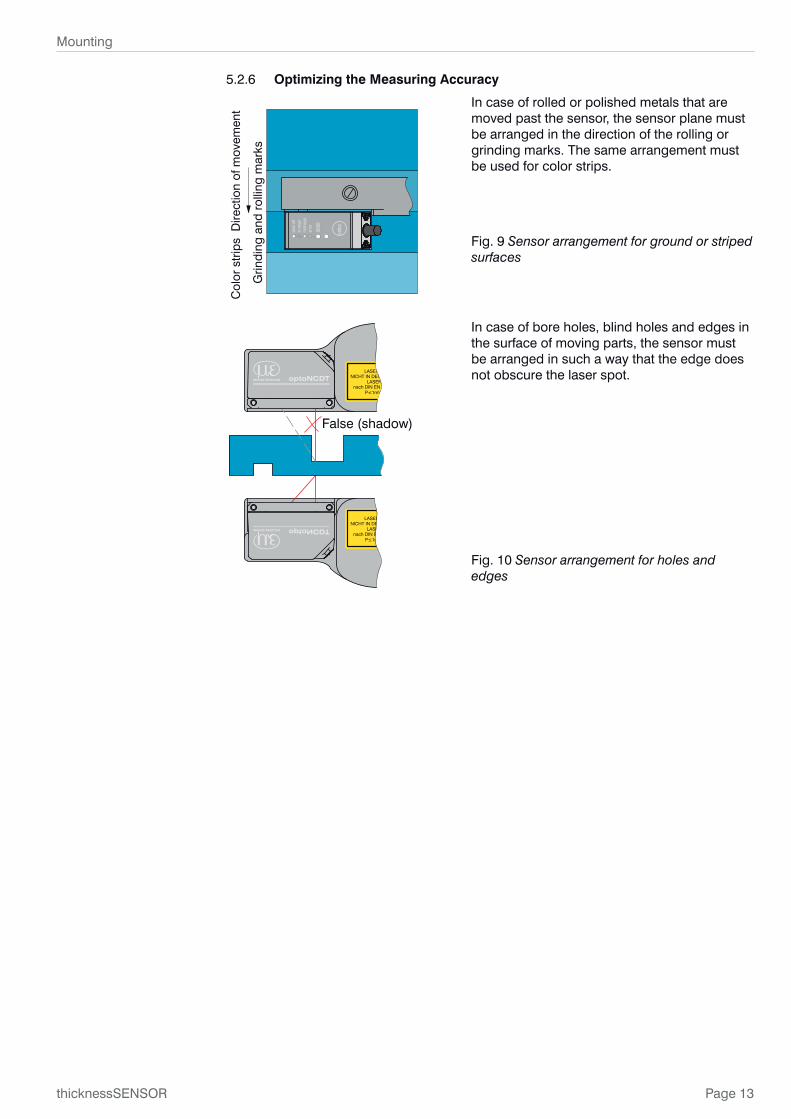
5.2.6 Optimizing the Measuring Accuracy
Col
or s
trip
s D
irect
ion
of m
ovem
ent
Grin
ding
and
rol
ling
mar
ks
llaassee
rr ooffff
iinn rraa
nnggee
mmiidd
rraanngg
eeeerr
rroorr
ssttaatt
eeoouu
ttppuutt
sseellee
cctt
In case of rolled or polished metals that are moved past the sensor, the sensor plane must be arranged in the direction of the rolling or grinding marks. The same arrangement must be used for color strips.
Fig. 9 Sensor arrangement for ground or striped surfaces
optoNCDT
≤
≤
optoNCDT
False (shadow)
In case of bore holes, blind holes and edges in the surface of moving parts, the sensor must be arranged in such a way that the edge does not obscure the laser spot.
Fig. 10 Sensor arrangement for holes and edges

Page 14
Mounting
thicknessSENSOR
5.3 Mechanical Fastening, Dimensional Drawing
140 (.1)
93 (3.7)(MR top) 75 (2.9)
(MR bottom) 65 (2.6)47 (1.9)
0
M6x1 - 6H(4x fastening thread)
0
135
(5.3
)
105
(4.1
)
45 (
1.8)
15 (
.6)
10 (.
4)
03
(.1)
38 (
1.5)
250
(.98
)
410
(16.
1)42
7 (1
6.8)
M6x1 - 6H(4x fastening thread)
0
25 (1)47 (1.9)
115 (4.5)
025 (
1)
115
(4.5
)
0
35 (1.4)
70 (2.8)
104 (4.1)
70 (
2.8)
55 (
2.2)
42 (
1.7)
20 (
.8) 0 0
25.5
(1)
(lase
rbe
am)
35(1
.4)
40 (
1.6)
70 (
2.8)
Fig. 11 Dimensional drawing thicknessSENSOR 10/200, dimensions in mm, not to scale

Page 15
Mounting
thicknessSENSOR
(MR top)75 (2.9)(MR bottom)65 (2.6)
93 (3.7)
47 (1.9)
00
0
25 (1)47(1.9)
115(4.5)
35 (1.4)
70 (2.8)
104 (4.1)
140 (.1)
M6x1 - 6H(4x fasteningthread)
M6x1 - 6H(4x fasteningthread)
(lase
r-be
am)
015
(.6
)
45 (
1.8)
105
(4.1
)
135
(5.3
)
627
(24.
7)10
(.
4)
610
(24)
115
(4.5
)
25 (
1)
0
38 (
1.5)0
3 (.
1)020
(.8
)42
(1.
7)55
(2.
2)70
(2.
8)
25.5
(1)
35 (
1.4)0
40 (
1.6)
70 (
2.8)
450
(17.
7)
Fig. 12 Dimensional drawing thicknessSENSOR 10/400, dimensions in mm, not to scale

Page 16
Mounting
thicknessSENSOR
165 (6.5)
118 (4.6)(MR top) 95 (3.7)
(MR bottom) 70 (2.8)
47 (1.9)
0
M6x1 - 6H(4x fastening thread)
M6x1 - 6H(4x fastening thread)
0
0
35 (1.4)
70 (2.8)
0 0
10 (.4)
0
37.5 (1.5)47 (1.9)
127.5 (5)
015
(.6
)
45 (
1.8)
105
(4.1
)
135
(5.3
)
104 (4.1)
70 (
2.8)
55 (
2.2)
42 (
1.7)
20 (
.8)
3 (.
1) 0
38 (
1.5)
250
(.98
)
410
(16.
1)42
7 (1
6.8)
25.5
(1)
35 (
1.4)
40 (
1.6)
70 (
2.8)
Lase
rbe
am
115
(4.5
)
25 (
1)
Fig. 13 Dimensional drawing thicknessSENSOR 25/200, dimensions in mm, not to scale

Page 17
Mounting
thicknessSENSOR
M6x1 - 6H(4x fasteningthread)
10 (.4)
(Las
er-
beam
)25
.5 (
1)35
(1.
4)40
(1.
6)70
(2.
8)0
115
(4.5
)
25 (
1)0
37.5 (1.5)
0
47 (1.9)
127.5 (5)
627
(24.
7)61
0 (2
4)
38 (
1.5)0
3 (.
1)
(MR top) 95
(MR bottom) 70
118
47
0
165
020
(.8
)42
(1.
7)55
(2.
2)70
(2.
8)
0
35 (1.4)
70 (2.8)
104 (4.1)
135
(5.3
)
105
(4.1
)
45 (
1.8)
15 (
.6) 0
M6x1 - 6H(4x fasteningthread)
450
(17.
7)
Fig. 14 Dimensional drawing thicknessSENSOR 25/400, dimensions in mm, not to scale

Page 18
Mounting
thicknessSENSOR
5.4 Control and Display Elements
LED State Meaning
LED state
LED output
green Target within the measuring range
yellow Target within the midrange
redError, e.g. target outside the measuring range, too low reflection
off Laser switched off
LED Output Meaning
green RS422 measured value output
yellow
RS422 and current output are switched off. The RS422 and the current output can be switched on. The web interface can be switched on.
red Measured value output current 4 ... 20 mA
off Sensor off, no supply
The Select key is disabled.
5.5 Electrical Connections
5.5.1 Connection Possibilities
Source Cable/Supply Terminal
PC
Dig I/O, Analog out
PS 2020
PS2020
Ethernet
SCD1420-x/THS
PC1420-x/THS
Fig. 15 Connection examples on ILD 1420
Different periphery devices can be connected to the 12-pin Analog Digital I/O 24 VDC connector, see Fig. 15. Power is supplied e.g. by the optionally available power supply PS 2020, see A 1.

Page 19
Mounting
thicknessSENSOR
5.5.2 Pin Assignment
Pin Color sensor cable, explanation Note
12
9
8
7
1
2
3
45
6
11
10
Solder side cable connector
9 red Operating voltage11 ... 30 VDC, typ. 24 VDC, P< 5 W
2 blue GND, supply Power supply ground
3 white Trigger input
4 green Master input
5 pink Switching output 1
6 yellow Switching output 2
7 black GND, switching outputs
8 gray Voltage output 1
10 violet Voltage output 2
11 gray-pink GND, analog
1 brown Current output 1
12 red-blue Current output 2
Housing, shield Connect to potential equalization
Fig. 16 Pin assignment of the 12-pin connector “Analog Digital I/O 24 VDC”
Please refer to the pin assignment diagram for further information, see Chap. A 3.
5.5.3 Power Supply
Nominal value: 24 V DC (11 ... 30 V, P < 5 W).
Switch on the power supply only after completing the wiring.
Connect the inputs “9” and “2” at the sensor with a 24V power supply.
Use the power supply unit for measurement devices only and not for drive units or simi-lar sources of pulse interference at the same time.
Sensor9
2
11 ... 30 VDC
thicknessSENSOR
MICRO-EPSILON recommends us-ing the optionally available power supply PS2020 for the sensor, see chapter A 1.
12-pin M12 ca-ble connector
Sensor cable
9 red +UB
2 blue GND
Fig. 17 Power supply connection
5.5.4 Current Output
The sensor provides a current output of 4 ... 20 mA.
i The current output may not be continuously operated in short-circuit operation with-out load resistor. Permanent short-circuit operation leads to thermal overload and thus to the automatic overload cut-off of the output.
Connect the output 1 or 12 (brown or red-blue) and 11 (gray-pink) at the sensor with a measurement device.
Sensor1/12
11
thicknessSENSOR
Iout12-pin M12 ca-ble connector
Sensor cable
1 or 12 brown or red-blue
I OUT1 IOUT2
11 gray-pink GND
Fig. 18 Wiring for current output
Page 20
Mounting
thicknessSENSOR
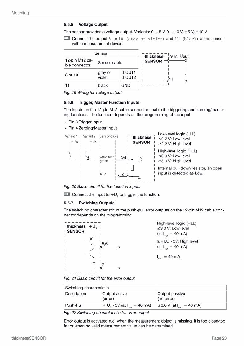
5.5.5 Voltage Output
The sensor provides a voltage output. Variants: 0 ... 5 V, 0 ... 10 V, ±5 V, ±10 V.
Connect the output 8 or 10 (gray or violet) and 11 (black) at the sensor with a measurement device.
Sensor8/10
11
thicknessSENSOR
Uout12-pin M12 ca-ble connector
Sensor cable
8 or 10 gray or violet
U OUT1 U OUT2
11 black GND
Fig. 19 Wiring for voltage output
5.5.6 Trigger, Master Function Inputs
The inputs on the 12-pin M12 cable connector enable the triggering and zeroing/master-ing functions. The function depends on the programming of the input.
- Pin 3 Trigger input - Pin 4 Zeroing/Master input
+UB+UB
Sensor cable
blue
Variant 1 Variant 2
white resp. green
3/4
2
thicknessSENSOR
Low-level logic (LLL) ≤0.7 V: Low level ≥2.2 V: High level
High-level logic (HLL) ≤3.0 V: Low level ≥8.0 V: High level
Internal pull-down resistor, an open input is detected as Low.
Fig. 20 Basic circuit for the function inputs
Connect the input to +UB to trigger the function.
5.5.7 Switching Outputs
The switching characteristic of the push-pull error outputs on the 12-pin M12 cable con-nector depends on the programming.
5/6
+UBthicknessSENSOR
7
High-level logic (HLL) ≤3.0 V: Low level (at Imax = 40 mA)
≥+UB - 3V: High level (at Imax = 40 mA)
Imax = 40 mA,
Fig. 21 Basic circuit for the error output
Switching characteristicDescription Output active
(error)Output passive (no error)
Push-Pull + UB - 3V (at Imax = 40 mA) ≤3.0 V (at Imax = 40 mA)
Fig. 22 Switching characteristic for error output
Error output is activated e.g. when the measurement object is missing, it is too close/too far or when no valid measurement value can be determined.

Page 21
Mounting
thicknessSENSOR
5.5.8 Connector and Sensor Cable
Never fall below the bending radius for the sensor cable of 30 mm (fixed) resp. 60 mm (dynamic).
i Unused open cable ends must be insulated or bluntly cut to protect against short circuits or sensor malfunctions.
Avoid excessive pull on the cables. If a cable of over 5m in length is used and it hangs vertically without being secured, make sure that some form of strain relief is provided close to the connector.
Connect the cable shield to the potential equalization (PE, protective earth conduc-tor) on the evaluator (switching cabinet, PC housing) and avoid ground loops.
Never lay signal leads next to or together with power cables or pulse-loaded cables (e.g. for drive units and solenoid valves) in a bundle or in cable ducts. Always use separate ducts.
Recommended strand cross-section for self-made connection cables: ≥ 0.14 mm².

Page 22
Operation
thicknessSENSOR
6. Operation
6.1 Getting Ready for Operation
Mount the thicknessSENSOR according to the installation instructions, see Chap. 5.3.
Connect the thicknessSENSOR to downstream display or monitoring units and to the power supply.
The laser diode in the sensors is activated by the controller.
Once the operating voltage has been switched on, the thicknessSENSOR runs through an initialization sequence. This is indicated by the momentary activation of all the LEDs. The initialization takes up to 10 seconds.
The thicknessSENSOR typically requires a start-up time of 20 min for reproducible mea-surements.
If the LED Output is off, this means that there is no operating voltage
If the LED State is off, this means that the laser light source has been switched off.
i The controller can only be operated via the web interface. The last setting applies.
6.2 Operation Using Ethernet
Dynamic web pages are generated in the thicknessSENSOR which contain the current settings of the thicknessSENSOR and the peripherals. Operation is only possible while there is an Ethernet connection to the thicknessSENSOR.
6.2.1 Requirements
You need a current web browser (e.g. Google Chrome or Mozilla Firefox) on a PC with a network connection. Decide whether the thicknessSENSOR should be connected to a network or directly to a PC.
The thicknessSENSOR is supplied as standard with a fixed IP address. If you do not want a static IP address, you can enable DHCP (Dynamic Host Configuration Protocol) for automatic IP addressing. The thicknessSENSOR is then assigned an IP address by your DHCP serve, see Chap. 6.2.2.
If you have configured your browser so that it accesses the Internet via a proxy server, please add the IP address of the thicknessSENSOR in the browser settings to the list of addresses which should not be routed via the proxy server.
Parameters Description
Address type Static IP address (standard) or dynamic IP address (DHCP)
IP addressStatic IP address of the controller (only active if DHCP has not been selected)
Subnet mask Subnet mask of the IP subnet
Gateway Gateway to other subnets
Fig. 23 Ethernet basic settings
“Javascript” must be enabled in the browser so that measurement results can be dis-played graphically.

Page 23
Operation
thicknessSENSOR
6.2.2 Access via Ethernet
Direct connection with PC, thicknessSENSOR with static IP address (factory setting)
Network
PC with static IP address PC with DHCP Controller with dynamic IP address, PC with DHCP
Connect the thicknessSENSOR (“Ethernet” socket) to the PC using a direct Ethernet connection (LAN). Use a LAN cable with a 7-pin M12 cable connector and an RJ-45 connector.
Connect the thicknessSENSOR to a switch using a direct Ethernet con-nection (LAN). Use a LAN cable with a 7-pin M12 cable connector and an RJ-45 connector.
The thicknessSENSOR needs a fixed IP address to establish a direct connection.
Start the program SensorFinder.
You will find this program on the supplied CD.
Click the Start Scan button. Select the required sensor from the list. To change IP address settings, click on the Change IP... button.
• Address type: static IP address • IP address: 169.254.168.150 1
• Gateway: 169.254.1.1 • Subnet mask: 255.255.0.0
Click on the Change button to transmit the changes to the thicknessSENSOR.
Click on the Start Browser button to connect the sensor to your standard browser. Alternatively, change the IP settings according to the settings on your PC (IP address ranges must match).
1) It is assumed that the PC LAN con-nection uses e.g. the following IP address: 169.254.168.1.
Wait until Windows has established a network connection (connection with limited connectivity).
Start the program SensorFinder.
You will find this program on the supplied CD.
Click the Start Scan button. Select the required sensor from the list.
Click on the Start Browser button to connect the sensor to your standard browser.
Enter the sensor in the DHCP server / notify the sensor to your IT Department.
The sensor is assigned an IP address by your DHCP server. You can query this IP address with the program SensorFinder.
Start the program SensorFinder.
You will find this program on the supplied CD.
Click the Start Scan button. Select the required sensor from the list.
Click on the Start Browser button to connect the sensor to your standard browser.
Interactive web pages for programming the thicknessSENSOR and peripherals are now shown in the web browser.
Fig. 24 SensorFinder auxiliary program for finding sensors and starting the web interface

Page 24
Operation
thicknessSENSOR
Parallel operation with web browser and ASCII commands is possible; the last setting applies. Do not forget to save.
Fig. 25 First interactive web page after calling the IP address
Use the upper navigation bar to access additional features (Preferences, Measuring and Help/Info).
All settings in the web page are implemented immediately after pressing the Apply button.
The appearance of the web pages can change depending on the functions and the peripherals. Each page contains parameter descriptions and tips on completing the web page.
Additional submenus can be accessed via the left-hand navigation column of the web pages, e.g. measuring rate or trigger mode.
i When programming has been completed, store all settings permanently in a set of parameters to ensure that these settings are available when the sensor is switched on the next time.
Fig. 26 Menu structure in the Preferences tab

Page 25
Operation
thicknessSENSOR
6.2.3 Measured Value Display with Web Browser
“Javascript” must be enabled in the browser so that measurement results can be displayed graphically.
Start the measured value display (Measuring) in the horizontal navigation bar.
1
2
3
4
5 6
7
8
9
10
Fig. 27 Display of the measurement and calculation results
1 Each curve can be deactivated and activated using the associated checkbox (checkmark). The Autozero function starts or stops a relative measurement for the thickness result.
2 Stop stops the diagram; data selection and zoom function are still possible. Save creates a CSV file (separation with semicolon) to store the last (approx. 50000) measured values. The file contains the accumulated measurement and calculation results including time information. The file is stored in the download area under Windows.
3 Averaging only affects the thickness result (thicknessSENSOR value); no avera-ging takes place in the laser sensors. The setting of the averaging can be carried out in parallel in the Preferences menu.
4 For scaling the measured value axis (y-axis) of the graphic, you can either select Auto (= autoscaling) or Manual (= manual setting).
Enable automatic scaling: Select Automatic from the drop-down menu.
Enable manual scaling: Select Manual from the drop-down menu.
The lowest and highest value of the scaling of the y-axis is automatically displayed. The y-axis can be scaled manually.
5 The master value is used to specify the thickness of a measurement object. Use the Set master value button to set the thickness result to zero, for example, if you want to make a differential measurement. The function is also used for a calibration measurement, see Chap. 3.3.
6 The current values of the two laser sensors and the calculated thickness value (thicknessSENSOR value) are displayed in the text boxes above the graphic.

Page 26
Operation
thicknessSENSOR
7 The zoom function scales the time axis during both the measurement and the offline analysis.
8 Mouseover function. When moving the mouse over the graphic in stopped state, curve points are marked with a circle symbol and the related values are displayed in a text box above the graphic.
9 Scaling of the x-axis can be defined by means of an input field below the time axis.
10 Scaling of the x-axis: When the measurement is running, you can use the left slider to enlarge (zoom) the total signal. If the diagram is stopped, you can also use the right slider. The zoom window can also be moved with the mouse in the center of the zoom window (arrow cross).
i By letting the diagram display run in a separate tab or browser window, you do not have to restart the display every time.
If the language is set to German, the measured values are stored with a comma as a decimal separator, otherwise with a period.
Only a limited number of recorded measurements can be stored (about 50,000). If more measured values are recorded, the oldest measured values are deleted.
i With high data rates, only a reduced number of measured values are displayed in the diagram!
6.3 Home Menu
Fig. 28 Start page screen
The Home menu is the first interactive web page after calling the IP address.
On the left side you can select the language from the Language selection drop-down menu, see Fig. 28. The language selection can also be made via the Preferenc-es > Extras > Language menu, see 6.4.1.
The upper navigation bar can be used to access additional features (Preferences, see Chap. 6.4, Measuring. and Help/Info, see Chap. 6.6.
NOTICE

Page 27
Operation
thicknessSENSOR
6.4 Preferences Menu
6.4.1 Language Selection
Go to the Preferences > Extras > Language menu.
This menu item allows you to change the language of the interactive web pages.
Language se-lection
System / English / German
Language of the interactive web pages
The language selection can also be made via the Home > Language selection menu, see Chap. 6.3.
6.4.2 Sensors
Go to the Preferences > Sensors menu.
Sensors Sensor 1 / Sensor 2
Connected sen-sor
ILD1420 SN xxxxxxxx Controller reads the serial numbers of the sensors used. A selection is not possible.
Search for con-nected sensors
Search sensors If no sensor is listed, it is possible to search for sensors.
Peak selec-tion
Available peaks Highest peak / first peak / last peak
Defines which signal is used in the array signal for the evalu-ation. Highest peak: Standard, peak with the highest intensity. First peak: Nearest peak to sensor. Last peak: Peak furthest away from sensor.
Submit peak
Selection of the measure-ment task
Available measurement tasks
Standard / changing surfaces / material with penetration
The selection of a measurement task loads a predefined sensor configuration that produces the best results for the selected material.
Submit measurement task
Laser Laser is ON. Switch off the laser Switches the laser light source on or off at the sensor on the software side.
Laser is OFF. Switch on the laser
Fig. 29 Preferences - Sensors screen
Standard Suitable for materials made of ceramic, metal or filled plas-tics
Changing surfaces Suitable for circuit boards (PCB) or hybrid materialsMaterial with penetration Suitable for plastics (POM, Teflon), materials with strong
penetration depth of the laserFig. 30 Overview of measurement task selection - Available measurement tasks
Fields with a gray background re-quire a selection.
Value
Dark bordered fields require the specification of a value.

Page 28
Operation
thicknessSENSOR
6.4.3 Measuring Rate
Go to the Preferences > Measuring rate menu.
The measuring rate indicates the number of measurements per second.
Select the required measurement frequency.
Measuring rate
0.5 kHz / 1.0 kHz / 2.0 kHz / 4 kHz
Use a high measuring rate for bright and mat measurement objects. Use a low measuring rate for dark or shiny measurement objects (e.g. black paint-ed surfaces) to improve the measurement result.
The measurement frequency is factory set to 2 kHz.
Fields with a gray background re-quire a selection.
Value
Dark bordered fields require the specification of a value.

Page 29
Operation
thicknessSENSOR
6.4.4 Filter / Averaging / Error Handling Inside thicknessSENSOR
Go to the Preferences > Filter / Averaging / Error handling inside thicknessSENSOR menu.
A number of filter types for measurement values are available. Filtering lowers the noise of the measurement signal which results in a better resolution. Filter width is used to specify the number of measurement values to which the filter applies.
Filter / Averaging / Error handling inside thickness-SENSOR
Measured value averaging
No averaging
Moving average for N values / Recursive average for N values / Medi-an filter for N values
Number of values for moving average
2 / 4 / 8 / 16 / 32 / 64 / 128 / 256 / 512
Number of values for recursive average
Number of values for median filter
Error handling in the case of no valid measured value
Error output, no measurement / Hold last valid value / Hold last valid value forever
If no valid measured value can be determined, an error value is output. If this impedes fur-ther processing, the last valid measured value can be kept for a number of measurement cycles, i.e. output repeatedly.
Moving average:
The selectable filter width N for successive measured values is used to calculate and issue the arithmetic average Mgl. Each new measured value is added, the first (oldest) measured value is removed from the averaging, see Chap. 6.4.2.
MW (k)k=1
N
NM =gl
MW = measured valueN = averaging numberk = continuous index (in the window)M gl = average or output value
Each new measured value is added, the first (oldest) measured value is removed from the averaging (from the window) again. In this way, short settling times for measured value jumps are achieved.
Example: N = 4
... 0, 1, 2, 2, 1, 3
2, 2, 1, 34
= M (n) gl
... 1, 2, 2, 1, 3, 4
2, 1, 3, 44
= M (n+1) gl
Measured values
Output value
i Moving average in the controller of the thicknessSENSOR allows only potentials of 2 for the averaging number N. The highest averaging number is 1024.Fields with a gray
background re-quire a selection.
Value
Dark bordered fields require the specification of a value.

Page 30
Operation
thicknessSENSOR
Application tips
- Smoothing of measured values
- The effect can be finely measured in com-parison to the recursive averaging.
- With uniform noise of the measured val-ues without spikes
- For a slightly rough surface, in which the roughness is to be eliminated.
- Also suitable for measured value jumps at relatively short settling times.
Signal without averaging Signal with averaging
Fig. 31 Moving average, N = 8
Recursive average
Formula:
MW + (N-1) x (n) M rek (n-1)
NM (n) = rek
MW = measured value
N = averaging value, N = 1 ... 32768
n = measured value index
M rek = average or output value
The weighted value of each new measured value MW(n) is added to (n-1) times the pre-vious average, see Chap. 6.4.2.
The recursive averaging enables very strong smoothing of the measured values, how-ever it needs very long settling times for measured value jumps. The recursive average shows low-pass behavior.
Application tips
- Allows very strong smoothing of the mea-sured values. Long settling times for mea-sured value jumps (low-pass behavior)
- Strong smoothing of noise without large spikes
- For static measurements, to smooth the signal noise particularly strongly
- For dynamic measurements on rough target surfaces to eliminate the roughness, e.g. paper roughness on paper webs
- For the elimination of structures, e.g. parts with uniform groove structures, knurled turned parts or coarse milled parts
- Not suitable for high-dynamic measure-ments
Signal without avera-ging Signal with averaging
Fig. 32 Recursive average, N = 8
Median:
The median is formed from a preselected filter width N for measurement values. The in-coming measured values are also sorted again after each measurement. Afterwards, the average value is output as the median. If an even number is selected as filter width N, the two average measurement values are added and divided by two, see Chap. 6.4.2.
3, 5, 7 or 9 readings are taken into account. This means that individual interference puls-es can be suppressed. However, the smoothing of the measured value curves is not very strong.

Page 31
Operation
thicknessSENSOR
Example: Median value from five measured values
... 1 2 4 5 1 3 5
... 0 1 2 4 5 1 3
Sorted measurement values: 1 3 4 5 5
Sorted measurement values: 1 2 3 4 5 Median = 3 (n)
Median = 4 (n+1)
Application tips
- Smoothing of the measured value curve is not very strong, used to eliminate outliers
- Suppresses individual interference pulses
- In short, strong signal peaks (spikes)
- Also suitable for edge jumps (only minor influence)
- For rough, dusty or dirty environment, to eliminate dirt or roughness
- Further averaging can be used after the median filterSignal without averaging
Signal with averaging
Fig. 33 Median, N = 7
Mea
sure
d va
lue
Mea
sure
d va
lue
Position value Position valueFig. 34 Original profile Fig. 35 Profile with median, N = 9
6.4.5 Zeroing / Mastering
Go to the Preferences > Zeroing / Mastering menu.
Zeroing / Master-ing
Mastering is ACTIVE Reset master value
Reset zero setting and mastering.
Mastering is INAC-TIVE
Set master value Activate zero setting and mastering. Value range for mastering: from -1024 to 1024 mm.
Master value in mm Value
Fields with a gray background re-quire a selection.
Value
Dark bordered fields require the specification of a value.

Page 32
Operation
thicknessSENSOR
6.4.6 Digital Interfaces
6.4.6.1 Selection of Digital Interfaces
Go to the Preferences > Digital interfaces > Digital interface se-lection menu.
Digital interfaces
Selection of digital inter-faces
Interface used for data output
Disabled No measured values are output via the digital interface.
Ethernet trans-mission of mea-sured values
Ethernet enables fast, non-real-time data transmission (pack-et-based data transfer). The measurement device can be configured via the web interface or by ASCII commands via a termi-nal program, see Chap. 6.4.6.3. Go to Ethernet settings, see Chap. 6.4.6.3.
Web diagram The recorded measured values are displayed in a diagram on the Measur-ing web page, see Chap. 6.5.
i The Ethernet interface is recommended for a measured value output with subse-quent analysis without direct process control. If a real-time measured value output is necessary for process control, the analog interfaces should be used.
Fields with a gray background re-quire a selection.
Value
Dark bordered fields require the specification of a value.

Page 33
Operation
thicknessSENSOR
6.4.6.2 Data Selection
Go to the Preferences > Digital interfaces > Data selection menu.
Fig. 36 Digital interfaces - Data selection screen
Here you can select data for transmission via digital interfaces.
From the sum of all available data those which are required for further processing can be selected. This data is then output one after the other in a defined sequence. You will find information about the data format, the output sequence and more details in the MEDAQLib instruction manual of MICRO-EPSILON, see Chap. 7.
i The display and storage of additional values is not possible in the web diagram.
Please use the thicknessSENSOR tool, which is available on request.

Page 34
Operation
thicknessSENSOR
6.4.6.3 Ethernet Settings
Go to the Preferences > Digital interfaces > Settings Ethernet menu.
Fig. 37 Ethernet settings screen
Ethernet settings
IP settings Address type Static IP address / DHCP
IP address Value Values for IP ad-dress / gateway / subnet mask. Only for static IP address
Subnet mask Value
Default gate-way
Value
Ethernet measured value transfer settings
Transmission type
Server/TCP The thickness-SENSOR pro-vides the mea-sured values as a server (trans-mission type: Server/TCP).
Port Value
The thicknessSENSOR provides the measured values as a server (transmission type: Server/TCP). A self-written program or a tool such as ICONNECT can be used as client. You will find the documentation of the data format in the MEDAQLib instruction manual of MICRO-EPSILON, see Chap. 7.
Fields with a gray background requi-re a selection.
Va-
lue
Dark bordered fields require the specification of a value.

Page 35
Operation
thicknessSENSOR
6.4.7 Analog Outputs
Go to the Preferences > Analog outputs menu.
6.4.7.1 Analog Output 1 and 2
Fig. 38 Preferences - Analog outputs screen
You can adjust the output signal, the output value, the output area and the scaling in this screen. After setting in the Filter / Averaging / Error handling in-side thicknessSENSOR > Measured value averaging menu, see Chap. 6.4.4, no averaging, you can select in the Analog outputs> Output signal menu between Fixed output value, Sensor 1 value and Sensor 2 value, see Fig. 39.
After setting in the Filter / Averaging / Error handling inside thick-nessSENSOR > Measured value averaging menu, see chapter 6.4.4, an averaging method or the median filter, you must set in the Analog output > Output signal menu the thicknessSENSOR: value, see Fig. 39.
Fig. 39 Analog output - Output signal drop-down menu
In the Preferences > Analog outputs > Analog output > Output area menu, you can select between analog output, current or voltage, see Fig. 40.

Page 36
Operation
thicknessSENSOR
Fig. 40 Analog output - Output area drop-down menu
In the Preferences > Analog outputs > Analog output > Scaling menu, you can select between Standard scaling and Two-point scaling, see Fig. 41.
Fig. 41 Analog output - Scaling drop-down menu
Analog output 1/2
Output sig-nal 1
Fixed output value Output value
Min to Max - value in V resp. mA
Data source can be a sensor signal, the result of the C-Box/2A of the thicknessSENSOR, or a fixed value within the output area.
Sensor 1/2: Measured value
Sensor 1/2: Intensity
Sensor 1/2: Shutter speed
Sensor 1/2: Reflectivity
thicknessSENSOR: Measured value
Output area Inactive / 0V ... 5V / 0V ... 10V / -5V ... 5V / -10V ... 10V / 4mA ... 20mA
Specification of the analog output, current or voltage with selectable value range.
Scaling Standard scaling Standard scaling outputs the entire measuring range of the sensor/controller.
Two-point scaling Two-point scaling requires the indication of the start and end of the range; value range: from -1024 to 1024 mm.
Two-point scaling (displace-ment and factor)
Start of range in mm Value
End of range in mm Value
1) Only one measuring value can be transferred.
Fields with a gray background re-quire a selection.
Value
Dark bordered fields require the specification of a value.

Page 37
Operation
thicknessSENSOR
6.4.8 Digital Ports
Go to the Preferences > Digital ports menu.
Under Digital input, see Chap. 6.4.8.1, you can configure the function input.
Under Digital outputs, see Chap. 6.4.8.2, you can configure the error out-puts.
6.4.8.1 Digital Input
The digital input can be used for mastering the thicknessSENSOR measured values.
Digital input Logic for digi-tal input
Low-level logic Selection of the logic for the digital input
≤0.7 V: Low level ≥2.2 V: High level
High-level logic ≤3.0 V: Low level ≥8.0 V: High level
6.4.8.2 Digital Outputs
Select the function of the error outputs.
Fields with a gray background re-quire a selection.
Value
Dark bordered fields require the specification of a value.

Page 38
Operation
thicknessSENSOR
Digital out-puts
Error out-put 1/2
Type Sensor 1/2: Error output 1/2 The value of the se-lected error output for the selected sensor is output.
Sensor 1/2: Measured value Outputs the range check result of mea-suring value / intensity value / shutter speed value / reflectivity value for the selected sensor. The allowed range is specified by the upper and lower limit input fields.
Sensor 1/2: Intensity
Sensor 1/2: Shutter speed
Sensor 1/2: Reflectivity
thicknessSENSOR: Measured value
Outputs the range check result for the thicknessSENSOR measuring value. The allowed range is spec-ified by the upper and lower limit input fields.
Low level The level is always low at the error output.
High level The level is always high at the error output.
Submit error output 1 / 2
6.4.9 Output Data Rate
Go to the Preferences > Output data rate menu.
Fig. 42 Preferences - Output data rate screen
The reduction of the output data rate causes only every nth measured value to be output. All other measured values are discarded. Any required averaging for n values must be set separately, see Chap. 6.4.4.
Fields with a gray background re-quire a selection.
Value
Dark bordered fields require the specification of a value.

Page 39
Operation
thicknessSENSOR
6.4.10 Trigger Mode
Go to the Preferences > Trigger mode menu.
Trigger mode Selected mode
No triggering
Level triggering There is a continuous measured value output as long as the selected level is applied. The data output is stopped afterwards. The trigger can be set to high level / low level.
Edge triggering The sensor outputs the previously set number of measured values or initiates a continuous measured value output after the trigger event. The trigger can be set to rising edge / falling edge.
Software triggering A measured value output is started as soon as a software command is triggered. The trigger moment is defined more inexactly. The sensor outputs the previously set number of measured values or initiates a continuous measured value output after the trigger event.
Fields with a gray background re-quire a selection.
Value
Dark bordered fields require the specification of a value.

Page 40
Operation
thicknessSENSOR
Selected mode
No triggering
Level triggering Measured value out-put at
High level
Active
logic
High-level logic (HLL)
Low level Low-level logic (LLL)
Edge triggering Rising edge High-level logic (HLL)
Falling edge Low-level logic (LLL)
Software trigge-ring
Number of measured values
Value
Active logic
The logic determines the level the trigger switches:
Low-level logic (LLL)≤0.7 V Low level≥2.2 V High level
High-level logic (HLL)≤0.7 V Low level≥8.0 V High level
Number of measured values
1...16382: Number of measured values to be output after a trigger event16383: Start of an infinitely measured value output after a trigger event
0: Stop of the trigger and ending an infinitely measured value output
i For all measuring tasks, level or edge triggering and external synchronization can-not be combined.
6.4.11 Load/Save Settings
Go to the Preferences > Load/save settings menu.
Fig. 43 Preferences - Load/save settings screen
All settings on the controller, e.g. connected sensors and calculation functions, can be permanently saved in user programs, so-called setups, in the controller.
i After the programming, all settings must be permanently stored under a setup no. (1 / 2 / 3 ... 8) in the controller, so that they are available again when the thickness-SENSOR is switched on the next time.
Fields with a gray background re-quire a selection.
Value
Dark bordered fields require the specification of a value.

Page 41
Operation
thicknessSENSOR
Load/save set-tings
Save to setup number
1 / 2 / 3 ... 8 Clicking this button saves the settings in the selected setup file.
Load from setup number
1/ 2 / 3 ... 8 Clicking this button loads the settings from the selected setup file.
Load All Settings All Settings
Interface settings only Interface settings include the network properties.
Measuring settings only Measuring settings only
6.4.12 Manage Settings on PC
Use this menu to save a backup copy of the settings to a PC or to restore saved settings to the controller.
i Save the controller settings before exporting or importing data, see Chap. 6.4.11.
Go to the Preferences > Load/save settings > Manage settings on PC menu.
Fig. 44 Preferences - Manage settings on PC screen
Fields with a gray background re-quire a selection.
Value
Dark bordered fields require the specification of a value.

Page 42
Operation
thicknessSENSOR
Export settings
If you want to save the settings, press the Export settings button, see Fig. 44.The Open thicknessSENSOR_Settings.txt Windows dialog box opens, see Fig. 45.
Fig. 45 Open thicknessSENSOR_Settings.txt Windows dialog box
Select Save file.
The file is saved under your downloads.
Save this download (your setup file) under any path you choose.All thicknessSENSOR settings are now saved in this file and can be loaded at any time again.
Import settings
If you want to load or import the settings, press the Choose settings file but-ton under Import settings, see Fig. 44.
The Choose file to upload Windows dialog box opens, see Fig. 46.
Select the appropriate parameter set file (*.txt) in the path you selected when export-ing and confirm with Open.
Fig. 46 Choose file to upload Windows dialog box
The thicknessSENSOR settings are read from the (*.txt) file and sent to the thickness-SENSOR.
Page 43
Operation
thicknessSENSOR
6.4.13 Extras
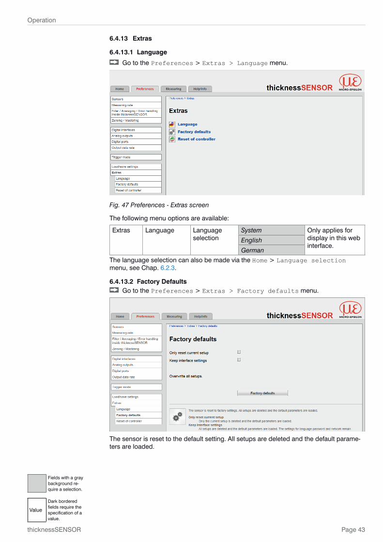
6.4.13.1 Language
Go to the Preferences > Extras > Language menu.
Fig. 47 Preferences - Extras screen
The following menu options are available:
Extras Language Language selection
System Only applies for display in this web interface.
English
German
The language selection can also be made via the Home > Language selection menu, see Chap. 6.2.3.
6.4.13.2 Factory Defaults Go to the Preferences > Extras > Factory defaults menu.
The sensor is reset to the default setting. All setups are deleted and the default parame-ters are loaded.
Fields with a gray background re-quire a selection.
Value
Dark bordered fields require the specification of a value.

Page 44
Operation
thicknessSENSOR
Make the following selection for factory defaults:
Intention Check-box
Meaning
Only reset current setup
Keep interface settings
Only the current setup is deleted and the default parameters are loaded.
Only reset current setup Keep interface settings
Current setup except interface set-tings is reset.
Only reset current setup Keep interface settings
All setups are deleted and the default parameters are loaded. The settings for language, password and Ethernet remain unchanged.
Overwrite all setups All setups are deleted and the inter-face parameters are reset.
Confirm the selection by pressing the Factory defaults button.
6.4.13.3 Reset of Controller
Go to the Preferences > Extras > Reset of controller menu.
Make the following selection for reset of controller:
Intention Check-box
Meaning
Also reset connected sensors Only the controller will be reset.
Also reset connected sensors Controller and all connected sensors will be reset.
Confirm the selection by pressing the Reset button.
The Reset button restarts the controller. The measurement is interrupted, unsaved changes are lost.

Page 45
Operation
thicknessSENSOR
6.5 Measuring Menu
Go to the Measuring menu.
1
2
3
4
5 6
7
8
9
10
Fig. 48 Measuring menu - Measuring program screen
The left window shows the following functions:1 Each curve can be deactivated and activated using the associated checkbox
(checkmark). The Autozero function starts or stops a relative measurement for the thickness result.
2 Stop stops the diagram; data selection and zoom function are still possible. Save creates a CSV file (separation with semicolon) to store the last approx. 50000 values. The file contains the accumulated measurement and calculation results including time information. The file is stored in the download area under Windows.
3 Shows which measured value averaging has been selected, see Chap. 6.4.4. You can also change the measured value averaging here and confirm with Submit. The averaging method is automatically updated in the Filter / Averaging / Error handling inside thicknessSENSOR menu, see Chap. 6.4.4.
4 For scaling the measured value axis (y-axis) of the graphic, you can either select Auto (= autoscaling) or Manual (= manual setting).
Enable automatic scaling: Select Automatic from the drop-down menu.
Enable manual scaling: Select Manual from the drop-down menu.
The lowest and highest value of the scaling of the y-axis is automatically displayed.
The y-axis can be scaled manually.5 The master value is used to specify the thickness of a measurement object. Use
the Set master value button to set the thickness result to the required value, for example, if you want to make a differential measurement. The function is also used for a calibration measurement, see Chap. 3.3.
6 The current values of the two laser sensors and the calculated thickness value (thicknessSENSOR value) are displayed in the text boxes above the graphic.

Page 46
Operation
thicknessSENSOR
7 The zoom function scales the time axis during both the measurement and the offline analysis.
8 Mouseover function. When moving the mouse over the graphic in stopped state, curve points are marked with a circle symbol and the related values are displayed in a text box above the graphic.
9 Scaling of the x-axis can be defined by means of an input field below the time axis.
10 Scaling of the x-axis: When the measurement is running, you can use the left slider to enlarge (zoom) the total signal. If the diagram is stopped, you can also use the right slider. The zoom window can also be moved with the mouse in the center of the zoom window (arrow cross).
If the language is set to German, the measured values are stored with a comma as a decimal separator, otherwise with a period.
i Only a limited number of recorded measurements can be stored (about 50000). If more measured values are recorded, the oldest measured values are deleted.

Page 47
Operation
thicknessSENSOR
6.6 Help/Info MenuThis page contains information about the serial and version numbers and the MAC ad-dress of controller and the attached sensors and an address block.
Fig. 49 Help/Info menu - Section 1 - Info controller
Fig. 50 Help/Info menu - Section 2 - Info sensor 1
Fig. 51 Help/Info menu - Section 3 - Info sensor 2
Fig. 52 Help/Info menu - Section 4 - Info GUI

Page 48
Software Support with MEDAQLib
thicknessSENSOR
7. Software Support with MEDAQLibMEDAQLib offers you a documented driver DLL. Therewith you embed the thickness-SENSOR, in combination with
- Ethernet card
- USB
into an existing or a customized PC software.
MEDAQLib
- contains a DLL, which can be imported into C, C++, VB, Delphi and many more programs,
- performs data conversions,
- works independent of the used interface type,
- is characterized by identical functions for the communication (commands),
- provides a consistent transmission format for all MICRO-EPSILON sensors.
For C/C++ programmers MEDAQLib contains an additional header file and a library file.
You will find the latest driver routine and documentation at:
www.micro-epsilon.de/download
www.micro-epsilon.de/link/software/medaqlib

Page 49
Liability for Material Defects
thicknessSENSOR
8. Liability for Material DefectsAll components of the device have been checked and tested for functionality at the facto-ry. However, if defects occur despite our careful quality control, MICRO-EPSILON or your dealer must be notified immediately.
The liability for material defects is 12 months from delivery. Within this period, defective parts, except for wearing parts, will be repaired or replaced free of charge, if the device is returned to MICRO-EPSILON with shipping costs prepaid. Any damage that is caused by improper handling, the use of force or by repairs or modifications by third parties is not covered by the liability for material defects. Repairs are carried out exclusively by MICRO-EPSILON.
Further claims can not be made. Claims arising from the purchase contract remain unaf-fected. In particular, MICRO-EPSILON shall not be liable for any consequential, special, indirect or incidental damage. In the interest of further development, MICRO-EPSILON reserves the right to make design changes without notification.
For translations into other languages, the German version shall prevail.
9. Service, Repair If the sensor, controller or sensor cable is defec-tive:
- If possible, save the current sensor settings in a parameter set, see Chap. 6.4.11 to reload them into the sensor/controller after the repair.
- Please send us the affected parts for repair or exchange.
If the cause of a fault cannot be clearly identified, please send the entire measuring system to:
MICRO-EPSILON MESSTECHNIK GmbH & Co. KG Königbacher Str. 15 94496 Ortenburg / Germany
Tel. +49 (0) 8542 / 168-0 Fax +49 (0) 8542 / 168-90 [email protected] www.micro-epsilon.com
10. Decommissioning, Disposal Remove the power supply and output cables from the thicknessSENSOR.
Incorrect disposal may cause harm to the environment.
Dispose of the device, its components and accessories, as well as the packaging materials in compliance with the applicable country-specific waste treatment and disposal regulations of the region of use.
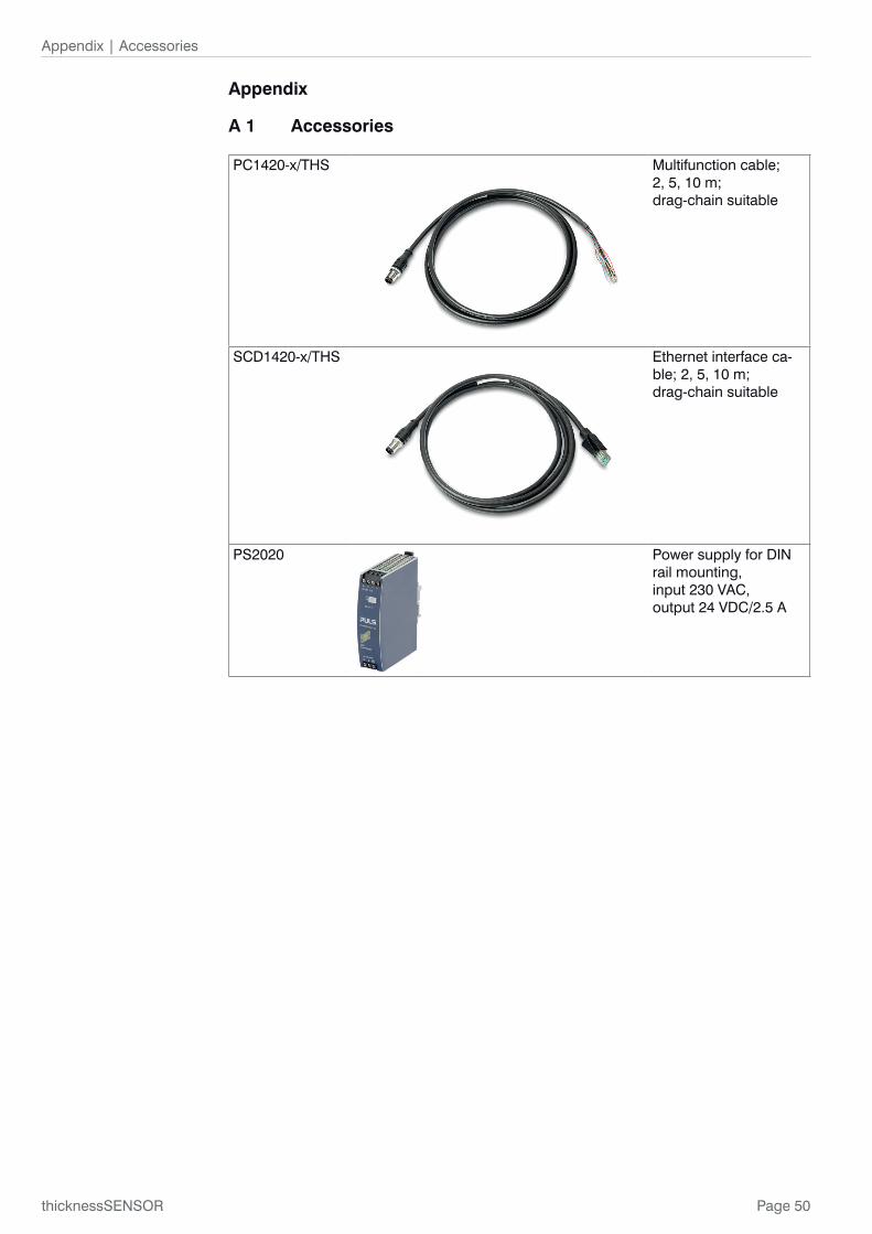
Page 50
Appendix | Accessories
thicknessSENSOR
Appendix
A 1 Accessories
PC1420-x/THS Multifunction cable; 2, 5, 10 m; drag-chain suitable
SCD1420-x/THS Ethernet interface ca-ble; 2, 5, 10 m; drag-chain suitable
PS2020 Power supply for DIN rail mounting, input 230 VAC, output 24 VDC/2.5 A

Page 51
Appendix | Factory Defaults
thicknessSENSOR
A 2 Factory Defaults
A 2.1 HomeLanguage selection: System
A 2.2 SensorsSensor 1
Available peaks: Highest peak
Available measurement tasks: Standard
Laser is on
Sensor 2
Available peaks: Highest peak
Available measurement tasks: Standard
Laser is on
A 2.3 Measuring RateMeasuring rate: 2.0 kHz
A 2.4 Filter / Averaging / Error Handling inside thicknessSENSORMeasured value averaging: No averaging
Error handling in the case of no valid measured value: Error output, no measurement
A 2.5 Zeroing/MasteringMastering is inactive. (No master value set.)
A 2.6 Digital interfacesSelection of digital interfaces
Interface used for data output: Ethernet transmission of measured values
Data selection
thicknessSENSOR: value: selected
Remaining data not selected
Ethernet settings
Address type: Static IP address
IP Address: 169.254.168.150
Subnet mask: 255.255.0.0
Default gateway: 169.254.1.1
Transmission type: SERVER/TCP
Port: 1024
A 2.7 Analog OutputsAnalog output 1
Output signal: thicknessSENSOR: value
Output area: 0 V...10 V
Scaling: Standard scaling
Analog output 2
Output signal: thicknessSENSOR: value
Output area: 0 V...10 V
Scaling: Standard scaling
Page 52
Appendix | Factory Defaults
thicknessSENSOR
A 2.8 Digital PortsDigital input
Logic for digital input: Low-level logic
Digital outputs
Error output 1 Type: Low level
Error output 2 Type: Low level
A 2.9 Output Data RateEvery 1-th measured value is output
Reducing applies to the following interfaces:
Analog: not selected
Ethernet data transfer: not selected
A 2.10 Trigger ModeSelected mode: No triggering
A 2.11 Load/Save SettingsSave to setup number: 1
Load from setup number: 1
Load: All Settings
A 2.12 ExtrasLanguage
Language selection: System
Factory defaults
Only reset current setup: not selected
Keep interface settings: not selected
Reset of controller
Also reset connected sensors: not selected

Page 53
Appendix | Pin Assignment
thicknessSENSOR
A 3 Pin Assignment
Eth
erne
tE
ther
net
SC
xx E
ther
net
Ana
log
Dig
ital I
/O
24V
Pow
er s
uppl
y
0V P
ower
sup
ply
Trig
ger
Inpu
t
24V
Mas
ter
Inpu
t
24V
Dig
ital O
utpu
t 1
24V
Dig
ital O
utpu
t 2
GN
D fü
r D
igita
l Out
puts
0-10
V A
nalo
g O
utpu
t 1
4-20
mA
Ana
log
Out
put 1
0-10
V A
nalo
g O
utpu
t 2
GN
D A
nalo
g O
utpu
ts
4-20
mA
Ana
log
Out
put 2
Shi
eld
thic
knes
sSE
NS
OR
4120
218
4120
219
4120
220
4120
221
RJ4
5
PC
cus
tom
er
9 2 4 3 5 6 7 8 1 10 11 12
Shi
eld
24V
/ 0.
5Acu
stom
erA
C
-
AC
+
13 14M
aste
r b
utto
n E
PLC
cus
tom
er
PC
xx M
ulti
func
tion
cabl
eR
ED
BLU
E
GR
EE
N
SH
IELD
WH
ITE
PIN
K
YE
LLO
W
BLA
CK
GR
AY
BR
OW
N
VIO
LET
GR
AY
-PIN
K
RE
D-B
LUE

Page 54
Appendix | ASCII Communication with the Sensor
thicknessSENSOR
A 4 ASCII Communication with the Sensor
A 4.1 GeneralThe ASCII commands can be sent to the thicknessSENSOR via the USB or Ethernet interfaces. All commands, inputs and error messages are in English. A command always consists of the command name and zero or more parameters, which are separated by spaces and are terminated with CR LF (corresponds to \r\n).
The echo is always active, i.e.:
- In the case of a command for setting parameters, first the command name, then OK or error and finally the prompt is returned as a response.
- In the case of a command for reading parameters, first the command name, then the parameter value and finally the prompt is returned as a response.
- In the case of a command with a multi-line response, first the command name and in the next lines the parameters are returned as a response.
A 4.2 Data ProtocolAll values to be output at the same time are grouped together for transmission to a frame. A maximum of 12 values/frame are possible. The measured values are transmitted via TCP/IP with 32 bits and USB with a maximum of 18 data bits.
Structure of a measured value frame:
- Sensor 1 Value
- Sensor 1 Intensity
- Sensor 1 Shutter
- Sensor 1 Reflectivity
- Sensor 2 Value
- Sensor 2 Intensity
- Sensor 2 Shutter
- Sensor 2 Reflectivity
- C-Box Value
- C-Box Counter
- C-Box Timestamp
- C-Box Digital
With the Ethernet transmission a header and then a sequence of data frames is transmit-ted with each package.
The header consists of:
- Preamble (32 bits): MEAS
- Order number (32 bits)
- Serial number (32 bits)
- Flags1 (32 bits), see Fig. 53
- Flags2 (32 bits), see Fig. 54, currently no function
- Bytes per frame (16 bits) / Number of frames in the package (16 bits)
- Frame counter (32 bits)
The data frames in the package are always complete (No frame can be distributed on several packages). Each frame consists of his selected measured values (up to 12). Each measured value has again 32 bits.

Page 55
Appendix | ASCII Communication with the Sensor
thicknessSENSOR
The valid value ranges for the thicknessSENSOR are as follows:
- Via USB:
� Sensor measured values and additional values depending on sensor, see also instruction manual of optoNCDT 1420, Chapter 7.5.1.
� C-Box measured values from 0 .. 131071, from 262073 … 262143 (18 bits) error values
� C-Box Counter from 0 .. 262143 (18 bits)
� C-Box Timestamp from 0 .. 262143 (18 bits)
� C-Box Digital from 0 .. 262143 (18 bits)
- Via TCP/IP (Ethernet):
� Sensor measured values and additional values depending on sensor, see also instruction manual of optoNCDT 1420, Chapter 7.5.1. However, an additional Hi Byte (0x00) is transmitted to comply with 32 bits.
� C-Box measured values from INT_MIN (-2147483648) to INT_MAX (2147483647)-11, INT_MAX-10 to INT_MAX are error values
� C-Box Counter from INT_MIN to INT_MAX
� C-Box Timestamp from INT_MIN to INT_MAX
� C-Box Digital from INT_MIN to INT_MAX
Flag 1 Bits Description Flag 1 Bits Description
0 Sensor 1 Value 11 Sensor 2 Intensity
1 unused 12 Sensor 2 Shutter
2 Sensor 2 Value 13 Sensor 2 Reflectivity
3 unused 14 C-Box Counter
4 C-Box Value 15 C-Box Timestamp
5 to 7 unused 16 C-Box Digital
8 Sensor 1 Intensity 17 to 30 unused
9 Sensor 1 Shutter 30 to 31 01 (fixed value, to distinguish from C-Box, where it is 00)10 Sensor 1 Reflectivity
Fig. 53 Description Flags 1 (Ethernet)
Flag bit Description
0 to 31 0
Fig. 54 Description Flags 2 (Ethernet)
Value Port Value range
Sensor 1 Value, Sensor 2 Value, C-Box Value
USB 0 ... 262072
Ethernet -INT_MAX ... INT_MAX -11 -2147483647 ... 2147483636
C-Box Counter, C-Box Timestamp, C-Box Digital
USB 0 ... 262143
Ethernet: -INT_MAX ... INT_MAX -2147483647 ... 2147483647
Fig. 55 Valid value ranges (raw)
Value Port Value range
Sensor 1 Value, Sensor 2 Value, C-Box Value
USB 262073 ... 262143
Ethernet: INT_MAX -10 ... INT_MAX 2147483637 ... 2147483647
Fig. 56 Error ranges (raw)

Page 56
Appendix | ASCII Communication with the Sensor
thicknessSENSOR
Value Port Calculation Unit
C-Box Value
USB [mm]
Digital * (C-Box Range Max - C-Box Range Min)
131072.0 Value = + C-Box Range Min
Ethernet Digital
1.0e+006 Value =
[mm]
C-Box Timestamp
USB Digital (Left shift by 8 bits)
1.0e+006 Value =
[s]
Ethernet Digital (unsigned int)
1.0e+006 Value =
[s]
C-Box-Counter
USB Digital without
Ethernet Digital (unsigned int) without
C-Box Digital
, see Fig. 57
Fig. 57 Calculation of the values
thicknessSENSOR Digital
Bits Description
0 Trigger IN (TRG IN) Pin header input
1 Multi-function input (MF IN) Pin header input
2 Laser ON (laser) Pin header input
3 Switching output S1 (OUT S1) Pin header output
4 Switching output S1 (OUT S2) Pin header output
5 Multi-function output Sensor1 output
6 Laser ON Sensor1 output
7 Switching input 1 Sensor1 input
8 Switching input 2 Sensor1 input
9 Multi-function output Sensor1 output
10 Laser ON Sensor2 output
11 Switching input 1 Sensor2 input
12 Switching input 2 Sensor2 input
13 to 15 (or 31) reserved (0)
Fig. 58 Description thicknessSENSOR Digital
During a restart or after a configuration change at the thicknessSENSOR, this initializes the sensors and the measuring restarts.

Page 57
Appendix | ASCII Communication with the Sensor
thicknessSENSOR
A 4.3 Commands Overview
Group Chapter Short description
A 4.4.1 Chap. A 4.4.1 Controller information
A 4.4.2 Chap. A 4.4.2 Search sensor
A 4.4.3 Chap. A 4.4.3 Sensor information
A 4.4.4 Chap. A 4.4.4 Read all settings
A 4.4.5 Chap. A 4.4.5 Language setting
A 4.4.6 Chap. A 4.4.6 Synchronization
A 4.4.7 Chap. A 4.4.7 Boot the controller
A 4.4.8 Chap. A 4.4.8 Triggering
A 4.4.8.1 Chap. A 4.4.8.1 Trigger selection
A 4.4.8.2 Chap. A 4.4.8.2 Trigger level
A 4.4.8.3 Chap. A 4.4.8.3 Number of measured values to be output
A 4.4.8.4 Chap. A 4.4.8.4 Software trigger pulse
A 4.4.9 Chap. A 4.4.9 Ethernet
A 4.4.10 Chap. A 4.4.10 Setting the measured value server
A 4.4.11 Chap. A 4.4.11 Transmission rate
A 4.4.12 Chap. A 4.4.12 Save parameters
A 4.4.13 Chap. A 4.4.13 Load parameters
A 4.4.14 Chap. A 4.4.14 Factory defaults
A 4.4.15 Chap. A 4.4.15 Measurement mode
A 4.4.16 Chap. A 4.4.16 Measuring rate
A 4.4.17 Chap. A 4.4.17 Measured value averaging controller
A 4.4.18 Chap. A 4.4.18 Measured value averaging sensor
A 4.4.19 Chap. A 4.4.19 Mastering / Zeroing
A 4.4.20 Chap. A 4.4.20 Selection digital output
A 4.4.21 Chap. A 4.4.21 Output data rate
A 4.4.22 Chap. A 4.4.22 Scale output values
A 4.4.23 Chap. A 4.4.23 Error handling
A 4.4.24 Chap. A 4.4.24 Data selection for USB
A 4.4.25 Chap. A 4.4.25 Data selection for Ethernet
A 4.4.26 Chap. A 4.4.26 Function selection multi-function input
A 4.4.27 Chap. A 4.4.27 Activate error output, switching output 1
A 4.4.28 Chap. A 4.4.28 Activate error output, switching output 2
A 4.4.29 Chap. A 4.4.29 Limit values
A 4.4.30 Chap. A 4.4.30 Data selection
A 4.4.31 Chap. A 4.4.31 Output area
A 4.4.32 Chap. A 4.4.32 Two-point scaling
A 4.4.33 Chap. A 4.4.33 Send command to connected sensor
A 4.4.34 Chap. A 4.4.34 Laser off / Laser on
A 4.4.35 Chap. A 4.4.35 Find thicknessSENSOR
A 4.5 Chap. A 4.5 Error values via USB
A 4.6 Chap. A 4.6 Error values via Ethernet

Page 58
Appendix | ASCII Communication with the Sensor
thicknessSENSOR
A 4.4 Commands
A 4.4.1 Controller InformationGETINFO
Querying the controller information. Output see example:
->GETINFOName: C-BoxSerial: 10000001Option: 000Article: 2420072MAC Address: 00-0C-12-01-06-08Version: xxx.xxx.xxx.xx->
A 4.4.2 Search SensorSCAN1
The controller searches for sensors connected to the Sensor 1 socket.
The SCAN2 command causes the controller to search for sensors connected to the Sensor 2 socket.
A 4.4.3 Sensor InformationGETINFO1
Provides information about the sensor connected to the Sensor 1 socket.
Example of a response if an ILD2300 is connected:
->GETINFO1
Name: ILD2300
Serial: 11020009
Option: 001
Article: 2418004
MAC Address: 00-0C-12-01-06-08
Version: 004.093.087.02
Measuring range: 20 mm
...
Imagetype: User
->If the sensor was not recognized by the thicknessSENSOR, the error E39 no sensor found is output.
The GETINFO2 command provides information about the sensor connected to the Sen-sor 2 socket.
A 4.4.4 Read all SettingsPRINT [ALL]
Print is used to output all query commands, for each line a response with command names in front.
- ALL: Provides further information
A 4.4.5 Language SettingLANGUAGE BROWSER|ENGLISH|GERMAN
Language of the displayed web pages.
- BROWSER means default language

Page 59
Appendix | ASCII Communication with the Sensor
thicknessSENSOR
A 4.4.6 SynchronizationSYNC NONE|INTERNAL|EXTERNAL [LLL | HLL]
- NONE: Sensors are not synchronized, the thicknessSENSOR runs with its own clock and takes just available sensor values.
- INTERNAL: thicknessSENSOR generates sync pulse
- EXTERNAL: External sync pulse is looped through to the sensors
� With an external triggering, you can switch between Low Level Logic (LLL) and High Level Logic (HLL).
� Low Level Logic (0 ... 0.7 to 2.8 ... 30)
� High Level Logic (0 ... 3 to 8 ... 30)
A 4.4.7 Boot the ControllerRESET [ALL]
The thicknessSENSOR is restarted.
- ALL: Also restart the sensors.
A 4.4.8 Triggering
A 4.4.8.1 Trigger SelectionTRIGGER NONE|EDGE|PULSE|SOFTWARE
Selection of the trigger mode
- NONE: No triggering
- EDGE: Flank triggering via TRG-IN (measured value output depends on TRIGGER-COUNT)
- PULSE: Gate triggering via TRG-IN (continuous measured value output as long as TRG-IN is active)
- SOFTWARE: Triggering via the TRIGGERSW command (measured value output de-pends on TRIGGERCOUNT)
Default = NONE
A 4.4.8.2 Trigger LevelTRIGGERLEVEL HIGH|LOW LLL|HLL
Sets the active logic level and the switching threshold for the trigger input.
- HIGH|LOW: active logic level
- LLL|HLL: switching threshold
� LLL = High Level Logic ==> LO = 0..0.7 Volt, HI = 8..30 Volt)
� HLL = High Level Logic ==> LO = 0..3 Volt, HI = 8..30 Volt)
Default = HIGH LLL
A 4.4.8.3 Number of Measured Values to be OutputTRIGGERCOUNT 0|1...16382|INFINITE|16383
Determines how many measured values are output after a trigger event.
- 1...16382: Number of measured values to be output after the trigger event
- INFINITE|16383: Start of continuous measured value output after a trigger event
0: Stops the continuous measured value output
Default = 1

Page 60
Appendix | ASCII Communication with the Sensor
thicknessSENSOR
A 4.4.8.4 Software Trigger PulseTRIGGERSW
Generation of a software trigger. If SOFTWARE is not selected in the trigger selection, the error message “E43 triggermode SOFTWARE disabled” is output.
If the command is sent again when the measured value output is active, the triggering is stopped and the measured value output is terminated.
A 4.4.9 EthernetIPCONFIG DHCP|STATIC [<IP address> [<Netmask> [<Gateway>]]]
Setting of the Ethernet interface.
- DHCP: IP address and gateway are automatically queried by DHCP. If no DHCP server is available, a link-local address is searched for after approx. 30 seconds.
- STATIC: Sets an IP address, the net mask and the gateway in the format xxx.xxx.xxx.xxx
If the IP address, net mask and/or gateway are not stated, their values remain un-changed.
A 4.4.10 Setting the Measured Value ServerMEASTRANSFER SERVER/TCP [<PORT>]
For measured value output via Ethernet: currently only TCP server is provided.
- The port is freely selectable between 1024 and 65535.
A 4.4.11 Transmission RateBAUDRATE <Baud rate>
Setting the interface baud rate to the PC. Possible variants: 115.200 (Default), 8.000.000, 4.000.000, 3.500.000, 3.000.000, 2.500.000, 2.000.000, 1.500.000, 921.600, 691.200, 460.800, 230.400, 9.600 Baud
A 4.4.12 Save ParametersSTORE 1|2|3|4|5|6|7|8
Save the current parameters under the specified number in the Flash. The data set which was saved last will be loaded when the thicknessSENSOR is restarted.
A 4.4.13 Load ParametersREAD ALL|DEVICE|MEAS 1|2|3|4|5|6|7|8
Read the parameters under the specified number from the Flash. The volume of data to be loaded must also be specified:
- ALL: All parameters are loaded.
- DEVICE: Only the basic device settings are loaded (interface parameters).
- MEAS: Only the measurement settings are loaded (all properties for the measure-ment).
A 4.4.14 Factory defaultsSETDEFAULT [ALL] [NODEVICE]
Sets the default values (reset to factory setting).
- ALL: All setups are deleted and the default parameters are loaded, otherwise only the current setup is deleted.
- NODEVICE: The IP address settings are temporarily retained.

Page 61
Appendix | ASCII Communication with the Sensor
thicknessSENSOR
A 4.4.15 Measurement ModeMEASMODE SENSOR1VALUE|SENSOR12THICK|SENSOR12STEP
Set measurement mode, possible are:
- SENSOR1VALUE: Measured value of sensor 1
- SENSOR12THICK: The measured values of sensor 1 and sensor 2 are subtracted from the measuring range and both results are added together. If the mastering is active, both values are subtracted from the internal mastering offset.
- SENSOR12STEP: Difference from measured value from sensor 1 minus measured value from sensor 2.
A 4.4.16 Measuring RateMEASRATE x.xxx
Measurement frequency in kHz with three decimal places.
Only measuring rates that support the sensors are permitted. If the synchronization is de-activated, values between 0.400 and 80.000 are permitted.
A 4.4.17 Measured Value Averaging ControllerAVERAGE NONE|MOVING|RECURSIVE|MEDIAN [<Averaging depth>]
Output averaging of the thicknessSENSOR. The average acts on the thicknessSENSOR measured value at all interfaces, also analog.
- MOVING: Moving average (averaging depth of 2, 4, 8, 16, 32, 64, 128, 256 and 512 possible).
- RECURSIVE: Recursive average (averaging depth of 2, 4, 8, ..., 32768 possible)
- MEDIAN: Median (averaging depth of 3, 5, 7 and 9 possible)
A 4.4.18 Measured Value Averaging SensorAVERAGE1 NONE|MOVING|RECURSIVE|MEDIAN [<Averaging depth>]
Averaging in the sensors. The average always acts on all distance and difference values to be output.
- MOVING: Moving average 1
- RECURSIVE: Recursive average 1
- MEDIAN: Median 1
The AVERAGE2 NONE|MOVING|RECURSIVE|MEDIAN [<Averaging depth>] com-mand sets the average of the sensor connected to the Sensor 2 socket.
A 4.4.19 Mastering / ZeroingMASTERMV NONE|MASTER <Master value>
Mastering of the thicknessSENSOR.
- NONE: Terminates the mastering
- MASTER: Setting the current measured value as master value
� Master value in millimeters (min: -1024.0 mm, max: 1024.0 mm)
� If the master value is 0, the mastering function has the same function as the zero setting.
A 4.4.20 Selection Digital OutputOUTPUT NONE|ETHERNET|HTTP|USB
Activates the data output at the desired interface.
- NONE: No measured value output
- ETHERNET: Output of measured values via Ethernet
- HTTP: Output of measured values via the thicknessSENSOR web page
- USB: Output of measured values via USB
1) Only those values which are also supported by the sensor are possible.

Page 62
Appendix | ASCII Communication with the Sensor
thicknessSENSOR
A 4.4.21 Output Data RateOUTREDUCE <Output reduction> ([ANALOG] [USB] [ETHERNET])|NONE
Reduces the measured value output for all available interfaces.
- 1: Output of every measured value
- 2 ... 1000: Output of each n-th measured value
A 4.4.22 Scale Output ValuesOUTSCALE_RS422_USB STANDARD|(TWOPOINT <Minimum measured value> <Maximum measured value>)
Sets the scaling of the C-BOXVALUE via USB.
The default scaling is for distance/level 0 to MR (Sensor1) and for thickness measure-ment 0 to MR (Sensor1) + MR (Sensor2) (MR = measuring range).
The minimum and maximum measured value must be indicated in millimeters. The avai-lable output area of the USB output is then spread between the minimum and maximum measured value. The minimum and maximum measured value must be between -1024.0 and 1024.0 mm with four decimal places. The max value must be greater than the min value.
A 4.4.23 Error HandlingOUTHOLD NONE|0|<Number>
Setting the behavior of the measured value output in case of error for the thicknessSEN-SOR measured value, not for the sensor values.
- NONE: No holding the last measured value, output of error value.
- 0: Infinite holding of the last measured value.
- Number: Holding the last measured value over a number of measuring cycles; then an error value (maximum 1024) is output.
A 4.4.24 Data Selection for USBOUT_USB NONE|([SENSOR1VALUE][SENSOR1INTENSITY][SENSOR1SHUTTER][SENSOR-1REFLECTIVITY][SENSOR2VALUE][SENSOR2INTENSITY][SENSOR2SHUTTER][SENSOR-2REFLECTIVITY][C-BOXVALUE][C-BOXCOUNTER][C-BOXTIMESTAMP][C-BOXDIGITAL])
Setting which values are to be output via USB.
- NONE: No output of a distance
- SENSOR1VALUE: Measured value of Sensor 1
- SENSOR1INTENSITY: Intensity of Sensor 1
- SENSOR1SHUTTER: Shutter speed of Sensor 1
- SENSOR1REFLECTIVITY: Reflectivity of Sensor 1
- SENSOR2INTENSITY: Intensity of Sensor 2
- SENSOR2VALUE: Measured value of Sensor 2
- SENSOR2SHUTTER: Shutter speed of Sensor 2
- SENSOR2REFLECTIVITY: Reflectivity of Sensor 2
- C-BOXVALUE: Calculated value of thicknessSENSOR
- C-BOXCOUNTER: Counter value of thicknessSENSOR
- C-BOXTIMESTAMP: Timestamp of thicknessSENSOR
- C-BOXDIGITAL: Digital inputs/outputs of thicknessSENSOR

Page 63
Appendix | ASCII Communication with the Sensor
thicknessSENSOR
A 4.4.25 Data Selection for EthernetOUT_ETH NONE|([SENSOR1VALUE][SENSOR1INTENSITY][SENSOR1SHUTTER][SENSOR-1REFLECTIVITY][SENSOR2VALUE][SENSOR2INTENSITY][SENSOR2SHUTTER][SENSOR-2REFLECTIVITY][C-BOXVALUE][C-BOXCOUNTER][C-BOXTIMESTAMP][C-BOXDIGITAL])
Setting which values are to be output via Ethernet.
- NONE: No output of a distance
- SENSOR1VALUE: Measured value of Sensor 1
- SENSOR1INTENSITY: Intensity of Sensor 1
- SENSOR1SHUTTER: Shutter speed of Sensor 1
- SENSOR1REFLECTIVITY: Reflectivity of Sensor 1
- SENSOR2VALUE: Measured value of Sensor 2
- SENSOR2INTENSITY: Intensity of Sensor 2
- SENSOR2SHUTTER: Shutter speed of Sensor 2
- SENSOR2REFLECTIVITY: Reflectivity of Sensor 2
- C-BOXVALUE: Calculated value of thicknessSENSOR
- C-BOXCOUNTER: Counter value of thicknessSENSOR
- C-BOXTIMESTAMP: Timestamp of thicknessSENSOR
- C-BOXDIGITAL: Digital inputs/outputs of thicknessSENSOR
A 4.4.26 Function Selection Multi-function InputMFIFUNC NONE|MASTER|SENSOR1|SENSOR2|SENSOR12 LLL|HLL
Function of the multi-function input, either mastering or output to one or both multi-func-tion outputs (sensor).
- NONE -> No function
- MASTER -> C-Box mastering
- SENSOR1 -> Multi-function output for sensor 1
- SENSOR2 -> Multi-function output for sensor 2
- SENSOR12 -> Multi-function output for sensor 1 and 2
- LLL -> Low Level Logic input
- HLL -> High Level Logic input
A 4.4.27 Activate Error Output, Switching Output 1ERROROUT1 SENSOR1ERROROUT1|SENSOR1ERROROUT2|SENSOR2ERROROUT1|SENSOR-2ERROROUT2|SENSOR1VALUE|SENSOR1INTENSITY|SENSOR1SHUTTER|SENSOR1RE-FLECTIVITY|SENSOR2VALUE|SENSOR2INTENSITY|SENSOR2SHUTTER|SENSOR2REFLEC-TIVITY|C-BOXVALUE|LOW|HIGH
Select the signal source for the switching output 1 (to the periphery).
The first four switch only one error output of the sensors.
The next nine monitor values from the thicknessSENSOR.
The last two switch the output to a level by command.
A 4.4.28 Activate Error Output, Switching Output 2ERROROUT2 SENSOR1ERROROUT1|SENSOR1ERROROUT2|SENSOR2ERROROUT1|SENSOR-2ERROROUT2|SENSOR1VALUE|SENSOR1INTENSITY|SENSOR1SHUTTER|SENSOR1RE-FLECTIVITY|SENSOR2VALUE|SENSOR2INTENSITY|SENSOR2SHUTTER|SENSOR2REFLEC-TIVITY|C-BOXVALUE|LOW|HIGH
Select the signal source for the switching output 2 (to the periphery).
The first four switch only one error output of the sensors.
The next nine monitor values from the sensors or the thicknessSENSOR.
The last two switch the output to a level by command.

Page 64
Appendix | ASCII Communication with the Sensor
thicknessSENSOR
A 4.4.29 Limit ValuesERRORLIMIT1 <Lower limit value><Upper limit value>
If a measured value or calculated value is to be monitored using ERROROUT1, the limits can be set here.
The minimum and maximum measured value is processed with four decimal places.
ERRORLIMIT2 <Lower limit value><Upper limit value>
If a measured value or calculated value is to be monitored using ERROROUT2, the limits can be set here.
The minimum and maximum measured value is processed with four decimal places.
A 4.4.30 Data Selection ANALOGOUT1 SENSOR1VALUE|SENSOR1INTENSITY|SENSOR1SHUTTER|SENSOR1REFLEC-TIVITY|SENSOR2VALUE|SENSOR2INTENSITY|SENSOR2SHUTTER|SENSOR2REFLECTIVI-TY|C-BOXVALUE|FIXED [Value]
Selection of the signal to be output via the analog output1.
For FIXED, the voltage/current value is indicated with four decimal places.
ANALOGOUT2 SENSOR1VALUE|SENSOR1INTENSITY|SENSOR1SHUTTER|SENSOR1REFLEC-TIVITY|SENSOR2VALUE|SENSOR2INTENSITY|SENSOR2SHUTTER|SENSOR2REFLECTIVI-TY|C-BOXVALUE|FIXED [Value]
Selection of the signal to be output via the analog output2.
For FIXED, the voltage/current value is indicated with four decimal places.
A 4.4.31 Output Area
ANALOGRANGE1 NONE|0-5V|0-10V|-5-5V|-10-10V|4-20mA
- NONE: No analog output (inactive)
- 0 - 5 V: The analog output1 outputs a voltage of 0 to 5 volts.
- 0 - 10 V: The analog output1 outputs a voltage of 0 to 10 volts.
- -5 - 5 V: The analog output1 outputs a voltage of -5 to 5 volts.
- -10 - 10 V: The analog output1 outputs a voltage of -10 to 10 volts.
- 4 - 20 mA: The analog output1 outputs a current of 4 to 20 mA.
ANALOGRANGE2 NONE|0-5V|0-10V|-5-5V|-10-10V|4-20mA
- NONE: No analog output (inactive)
- 0 - 5 V: The analog output2 outputs a voltage of 0 to 5 volts.
- 0 - 10 V: The analog output2 outputs a voltage of 0 to 10 volts.
- -5 - 5 V: The analog output2 outputs a voltage of -5 to 5 volts.
- -10 - 10 V: The analog output2 outputs a voltage of -10 to 10 volts.
- 4 - 20 mA: The analog output2 outputs a current of 4 to 20 mA.
A 4.4.32 Two-point Scaling
ANALOGSCALE1 STANDARD|(TWOPOINT <Minimum measured value> <Maximum mea-sured value>)
Setting the scaling of analog output1.
The standard scaling is for distances -MR/2 to MR/2, for thickness measurement 0 to 2 MR (MR = measuring range), for intensity 0 to 100 %.
If the minimum and maximum measured value is ‘0’, standard scaling is used.
The minimum and maximum measured value must be indicated in millimeters (distance/thickness) or % (intensity).
The available output area of the analog output is then spread between the minimum and maximum values. The minimum and maximum measured value must be between -1024.0 and 1024.0 mm with four decimal places.
The minimum and maximum measured value is processed with four decimal places.
ANALOGSCALE2 STANDARD|(TWOPOINT <Minimum measured value> <Maximum mea-sured value>)

Page 65
Appendix | ASCII Communication with the Sensor
thicknessSENSOR
Setting the scaling of analog output2.
The standard scaling is for distances -MR/2 to MR/2, for thickness measurement 0 to 2 MR (MR = measuring range), for intensity 0 to 100 %.
If the minimum and maximum measured value is ‘0’, standard scaling is used.
The minimum and maximum measured value must be indicated in millimeters (distance/thickness) or % (intensity).
The available output area of the analog output is then spread between the minimum and maximum values. The minimum and maximum measured value must be between -1024.0 and 1024.0 mm with four decimal places.
The minimum and maximum measured value is processed with four decimal places.
A 4.4.33 Send Command to Connected SensorTUNNEL1 <Command for Sensor 1>
The command is enclosed in quotation marks and is sent by the thicknessSENSOR with a <CRLF> to the sensor connected to the Sensor 1 socket. The response of the sensor is packaged and returned in quotation marks.
If no prompt is received, then the response is waited for up to 15000 ms and then an error is returned.
If no sensor has been detected in the thicknessSENSOR, an error message is returned immediately.
Example of a tunnel communication, the echo in the sensor is switched off:
Command: TUNNEL1 „LASERPOW“<CRLF>
Response: TUNNEL1 „LASERPOW FULL“<CRLF>->
Command: TUNNEL1 „LASERPOW FULL“<CRLF>
Response: TUNNEL1 „<CRLF>“<CRLF>->
Command: TUNNEL1 „GETINFO“<CRLF>
Response: TUNNEL1 „<CRLF><CRLF>Name:ILD2300<CRLF>Seri-al:1020004<CRLF>... “<CRLF>->
The TUNNEL2 command sends commands to the sensor connected to the Sensor 2 socket.
A 4.4.34 Laser off / Laser onLASERPOW1 OFF|ON
Line for laser on/off. When the laser is enabled by a jumper between Laser ON and GND, it can be switched via the LASERPOW1 OFF/ON command.
The LASERPOW2 command works in the same way and is addressed to the sensor con-nected to the Sensor 2 socket.
A 4.4.35 Find thicknessSENSORSearch the thicknessSENSOR by using the Sensorfinder, see chapter 6.2.2.
A 4.5 Error Values via USB
262073 USB scaling underflow
262074 USB scaling overflow
262075 Too much data for this baud rate
262079 Measure value cannot be calculated
262080 Measure value cannot be examined, global error
A 4.6 Error Values via Ethernet
7ffffff8 Measure value cannot be calculated
7ffffff7 Measure value cannot be examined, global error

MICRO-EPSILON MESSTECHNIK GmbH & Co. KG
Königbacher Str. 15 · 94496 Ortenburg / Germany
Tel. +49 (0) 8542 / 168-0 · Fax +49 (0) 8542 / 168-90
[email protected] · www.micro-epsilon.com
X9751370-A031038HDR
*X9751370-A03*
MICRO-EPSILON MESSTECHNIK