construction of langham place by raymond wong wai...
TRANSCRIPT

Langham PlaceConstruction of by Raymond Wong Wai Man
Project Backgroundand CoverageMong Kok is one of the mostdensely populated and ageddistricts in the metro area of HongKong. Some streets within the areahave a development history whichcan date back up to the end of the19th Century. Being a city underfast development, majority of theold streets and historic buildingswere demolished to give way fordevelopment under usual free-market environment. Except forsome mode rn commerc ia lbu i l d i ngs us ing as o f f i ce ,entertainment or retail purposes,majority of the remaining buildingsin the district were constructedafter the World War I I wi thaveraged age ranging from 30 to50 years. Due to the insufficiencyof space and urban facilities whichinherited from outdated cityplanning, the district is deterioratedin a very fast manner and createda lot of associated social problems.In view of this, through the Land

Development Corporation (reformedas the Urban Renewal Authority in2000), the government started toresume altogether about 150 blocksof old buildings within an areabounded by 7 streets. After thevocation of the land, the project wasdeveloped by a private developerunder carefully negotiated contract.The development was known as theLangham Place afterward.
The Langham Place project coversa total land area of about 12,000sq m, which is further sub-divided intotwo lots of land, separated by theShanghai Street in the middle. Thelarger lot (Site A) is an island site,bounded by the Argyle Street,Portland Street, Shanghai Street andShan Tung Street on the four sides,with an area of about 7950 sq m. SiteA accommodates a 59-storey officetower block, a 16-storey retail mall withshopping and entertainment facilities,and a 5-level basement uses as retailand carpark that stretches the entirearea of Site A.
The smaller site (Site B) isopened two sides to ShanghaiStreet and Reclamation Street, andwith the shorter ends abutted toexisting buildings, with an areaabout 4,300 sq m. This site consistsa 2-level basement while the upperstructure is a 42-storey hotel buildingwith 750 rooms. Except for anentrance foyer for the hotel, majorityof the area on the ground level isused as a public light bus terminus
that formed part of the groundtransportation relief strategies for theexisting congested neighborhood indowntown Mongkok. The totaldevelopment involved a gross floorarea (GFA) of about 167,400 sq m.
Connection provisions in thedevelopment have been provided inthe design in order to enhance theflow between the two sites. A 2-waytraffic vehicular tunnel is constructedto link up the two basements whichboth served for car parking purpose.This tunnel is required due to the sitelayout constraints that only avehicular entrance point at Site A isapproved by the government for thereason not to further congest therelatively narrow roadway in thearea in particular in view of theprovision of a new public light busterminus situated at Site B after thecompletion of the project.
The other linkage provisionbetween the two sites is theconstruct ion of two coveredpedestrian footbridges on Level 3and 4, which provide a convenientthroughway for users between thehotel block and the retail mall.
Construction HighlightsThe major construction works for theproject can be sub-divided into fivecore e lements , tha t i s , thefoundations, the construction of themain tower, the basement structureon site A, the retail mall structure,and the hotel block on site B.
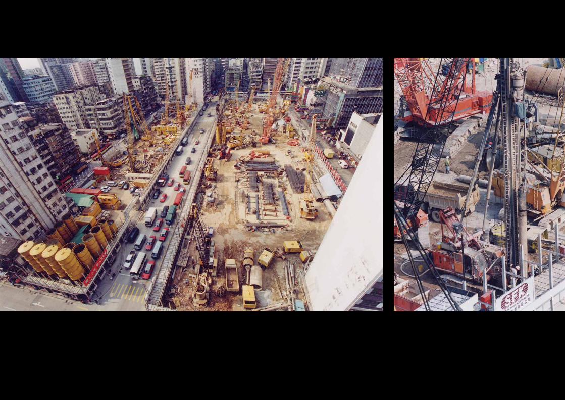
Foundation in generalThe foundation works were carriedout at the same time for the bothsites at the end of 1999. Thecontract involved the forming ofvarious cut-off systems in the formof sheet pile wall, diaphragm walland small diameter pipe-pile wall; aswell as the usual bored piles assupport for the upper structures.Majority of the bored piles were2.5m in d iameter formed byreversed circulation drilling processand seated on bedrock averaged45m below ground. To facilitate theconstruction of the basement atconvenient stages at a later time, asection of sheet pile wall were alsoprovided. This arrangement couldallow the construction of thefoundation raft and the basementportion of the main tower in anadvanced phase before the fullcommencement of the basementstructure under the retail podium.
The main towerThe tower founded on a 5m RC raftconstructed in a bottom-up manner.To facilitate the construction of theraft, a 42m x 42m cofferdam wasformed with diaphragm wall lined on3 sides and sheet pile wall on theother as cut-off provision, andlaterally supported by a complicatedstrut and bracing system with 7layers of lateral supporting frame.The support system also provideda work platform on which mobile
cranes and dumping trucks werestationed during the excavationprocess. The formation level of thecofferdam was about -28m.p.d. Themain structures located inside thecofferdam included the core wall,four composite columns and 6 otherminor columns in RC for the supporto f the upper s t ructure. Thebasement structure, constructed ofin-situ RC and traditional timberformwork, was done in a usualbottom-up manner with the wallsand floors cast in convenientsections.
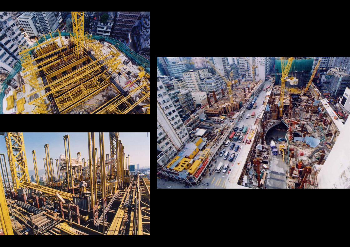
The core wall and the compositecolumns continued upwards fromthe basement until they reachedLevel 5 where a 5m-thick transferplate located. A falsework systemerected in tubular scaffold anduniversal steel beams was providedto facilitate the casting of the transferplate. Upon the completion of thetransfer plate, a set of jump form wasassembled for the forming of thecore wall for the upper structure.
Column configuration was in 4composite mega-columns plus 6 in-situ RC side columns for floorsbelow the transfer plate, which wasre-configured to 12 in-situ RCcolumns layout with shorter spanarrangement above the transferplate. The floor system is of usualmain/secondary beams design,which was constructed in RC usingt rad i t iona l t imber fo rm andconnected to the core wall with build-

in couplers. Headroom of the typicalfloors is 3.9m and the averagecoverage of typical floor is about1,000 sq m in size. A 4-day cyclewas adopted for the construction oftypical floor with the core wallconstructed using a hydraulic liftingslip form in an advanced phase andfloor slab in traditional timberformwork.
The core wall measured about15m x 32m on plan with 2m-splayedcorners. The maximum thickness ofwall is 1.2m for the lower floors(along the edge wall at the longaxles), and reduced to 600mm whenreaching the upper levels.
There are 2 outrigger systemsincorporated in the superstructure ofthe building as a stiffening design.They are located on Level 16 andLeve l 38 respec t i ve l y. Theoutriggers are in simple bracingf rame des ign, w i th inc l inedcomposite tie members stretchedfrom the 2 shorter axles at the cornerof the core wall and ties rigidly withthe external frame. Instead of a fully-braced belt truss system, a simpletruss in the form of an inverted “A”configuration is adopted as theexternal truss of the outrigger.
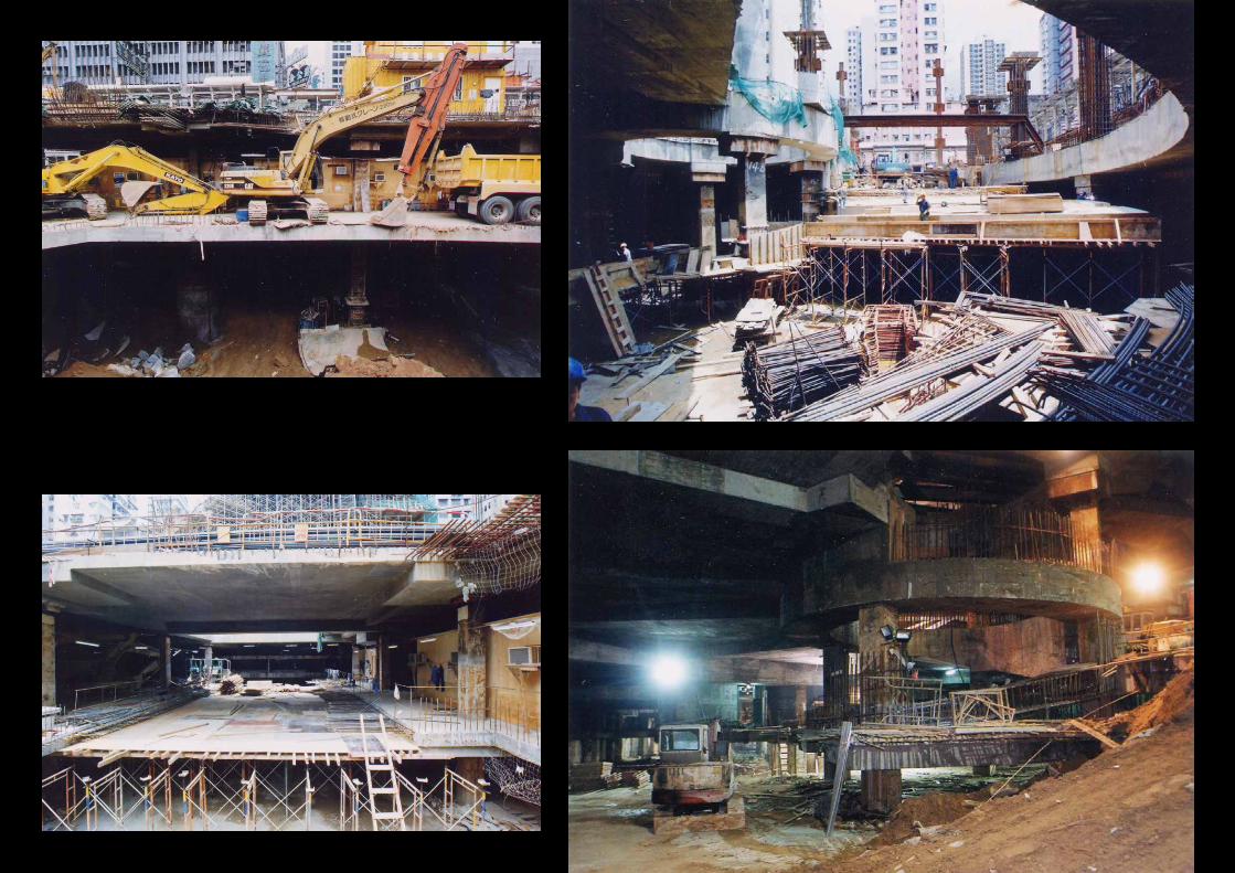
Basement Structure on Site AThe basement under the retail mallat Site A was constructed using atop-down approach. Total volume ofexcavation involved in the basementis about 170,000 cu m, in which
majority of the sub-soil is of made-ground with small amount of marinedeposits. The basement structureconsists of 5 levels, with the upper2 levels use mainly as retail, whilethe remaining as car parkingpurposes. The basement was joinedto the portion under the main towerwhich was constructed in a bottom-up manner in an advanced stageduring the progress of basementconstruction.
One very spectacular structure inthe basement is a 36m diametervehicular ramp which serves as anaccess for vehic les into thebasement carpark from an entranceat Shan Tung Street. The rampserved as an important provision forspoil disposal and material deliveryduring the peak period of basementexcavation and construct ion.Besides, the escalator voids locatedinside the basement was also madeuse of for similar purposes duringthe construction process.
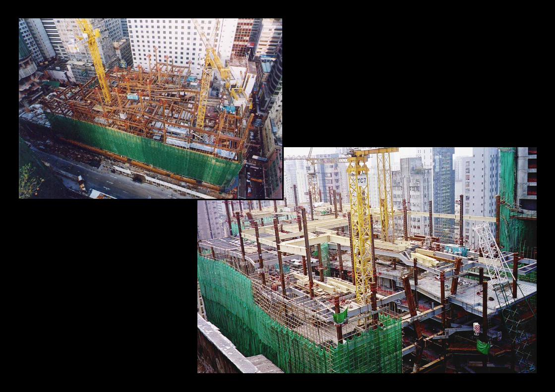
The Retail MallThe retail mall is a very complicatedstructure with the lower portion (fromground to Level 4, the main deck)constructed of in-situ RC, and theupper portion in a structural steelcomposite. In addition, there is agrand atrium located in between theoffice block and the mall structure,which provides an averaged 52mhigh unobstructed space above themain deck at Level 4 that forms the
highly impressive entrance to theretail mall.
The basic layout of the mallstructure roughly follows a 8.5m-gridsystem but with the out-setting andmulti-level design on each floor. Theactual layout exhibits a veryinteresting irregularity that makesthe spatial arrangement inside themall interior having an extremelynovelty look in the design.
The grand atrium is of no doubtan eye-catching structure whichprovides a covered void inside themall with 77,000 cu m of space. Thegrand atrium is a space trusssupported y 10 columns on twosides of the atrium and connectedby the metal roof to form a portalframe. The columns are made oftubular steel trusses in rectangularshape. The height of columnsranges from 51m to 63m from level4 to the roof truss. Space betweenthe columns is tied by truss cablesand tubular girders for the mountingof the glass wall at a later stage.
The steel roof curves slightlyupward to provide cover for theremaining portion of the retail malls t ruc ture . The s tee l roof isconstructed of 14 sets of maintrusses, with an average depth of3.5m each. The roof cover employeda 6-layered aluminum deckingsystem with basic insulation andwaterproofing membrane within.
Besides the grand atrium, thereare 2 other atrium provisions placed
inside the main structure of the mallin which two fast-track escalatorsystems were located. There is alsoa provision for a skating rink onLevel 12 with averaged 15mheadroom, and cladded on the sidesw i t h g l ass wa l l t o p rov i detransparency and natural lighting forthe area.
Hotel Block on Site BThe hotel block started its basementwork in August 2001. The basementadopted a rather tradition method toconstruct, that is, it was done in abottom up arrangement, with theexcavation carried out in layersstarting from the ground level, untilit reached the formation level wherethe pile caps were constructed. Theaveraged depth of excavation wasabout -14m from street level with themax imum depth a t -19m toaccommodate the lowest lift pit. Sidesuppor t was by the use o fdiaphragm wall with a section ofpipe-pile wall at the north end whereit abutted to existing buildings. Sixlayers of strut frame were providedas the lateral support system, witha 50m x 12m temporary platformerected on top as work station tofacilitate the excavation process.
In order to provide a 4-lane publiclight bus terminus at the ground levelof the site, the floor span on thelower levels of the hotel block ismaximized by the use of thinc o m p o s i t e c o l u m n s i n a n

approximate 9m and 15m spanlayout. The arrangement continuesupward until it reached Level 11where the 3.2m-thick transfer platelocates.
The structure above Level 11 isused as hotel guestrooms. Thestructure is comprised of twosections, one is the major core wallsystem which housed the lift shaftsand staircases; the other is the shearwall block for the typical guestrooms.The averaged 500mm-thick corewall system was constructed in anadvanced phase using a crane-liftedgang form, while the averaged300mm-thick shear walls wereconstructed using large-panel typesteel form. The 3.15m-clearancefloor system in this case employeda tradit ional t imber formworkpropped with standard tubularscaffold.
Special problems encounteredduring the construction processThe Langham Place pro jectencountered a lot of work difficultiesduring the construction due topractical reasons. Below show someof these examples.1. E x t r e m e l y c o n g e s t e d
environment surrounding the siteThe site (Site A and B) wasbounded by one main road with3-lane dual way traffic and 4 busyinner roadways with averagedwidth below 12m. The siteactivities such as the removal of
excavated spoil and the deliveryof materials during the basementand superstructure construction,in particular created numerousdisturbances that very carefulplanning and coordination for thetraffic arrangement was required.
2. Large work f rontage andcoverageThe entire project excluding thefoundation works took 36 monthsto complete. The peak periodarrived about 15 months after thecontract commencement in
August 2001. During this period,the excavation work for thesubstructure was basicallyc o m p l e t e d , w h i l e t h econstruction of the main towerbegan to reach its typical cycle.At the same time on the retailma l l por t ion , the pod iumstructure in RC was completedthat followed by the erection ofthe upper structure in structuralsteel. The basement constructedin top-down arrangement wascarried out in parallel to the other
major works. At a result, therewere more than 600 workersworking in the site and with acash flow of US$16 million permonth during the climax period.
3. Beside the general engineeringand technical concerns in theinstallation of the steel framebuilding, there was also theproblem of working at highaltitude especially for the retailmall structure. This was furtherworsened by the existence of anumber of long-span and high-

headroom atrium spaces whichinvo lved very heavy pre-assembled components andother temporary supportingfalsework.
4. Difficult site layout planning tomeet the construction operationThe large work frontage anddynamicity of the constructionoperations within a congestedsite demands very accuratesupport in the s i te layoutprovision and planning. Sitefacilities and equipment were nota major concern in the project.How to locate the requiredservices was often a problem inparticular where the work frontwas difficult to access, located ata high altitude, or situated atenclosed work area such aswithin the top-down basement orinside an atrium space within theenclosed structure on the upperlevel.
5. Delicate finishing worksThe pro jec t invo lved theconstruction of a Grade A officetower and a h igh-qua l i t yshopping complex in which veryexpensive and delicate finishingworks were involved. Thefinishing works were of a widevariety of nature includinggeneral finishes glass work,stone work, woodwork andpavior works. Some were ofinterior design nature whereextremely high workmanship and
touching-up requirements weredemanded especially in the hotelblock. Some were exterior worksincluding inclined or overhanginginstallation such as the deck andcladding panel for the curvy roofof the retail mall. These workswere often very expensive andfragile, having safety concernwhen installed, sometime alsorequiring necessary site layoutplanning support to facilitatework.In order to obtain the best result,
the contractor of the project has tomaintain a very strong team on site totake care of the work under a shortterm and intermediate term basis. Therole of the team was responsible totake care of matters such as, workscoord ina t ion , p lann ing andschedul ing, temporary workprovisions, construction safety andother logistic support, as well as tomaintain a comprehensive temporarytraffic management network withrelevant parties and authorities toensure the thorough running of thenearby public traffic during the peakperiod of construction.
A t t he same t ime , someinnovative provisions or specialequipment were also introduced toimprove the efficacy of work. Theseincluded the use of an advancedClimb Form for the construction ofthe core wall of the office tower,which is a self-cl imbing pre-fabricated system formwork. The
system comprised of steel panelformwork, a supporting steel frameand a synchronized hydraulicjacking system. The formwork alsoreduced the lifting work load of thetower crane and expedited theformwork releasing process afterconcreting. In addition, the formworkcan cater for curved structure by theuse of the rigid steel frame. Theformwork also produced a goodvertical alignment by monitoring thesteel formwork position on thesupporting frame. Erection of theformwork was done relatively easyby moving the large panels sidewardon hanging rollers and rails.
Other provisions such as the useof a climbing work screen ontemporary guide rail to protectexterior work activities at highlevel, the use of floor-to-floormaterial hoist with a 4m x 6mplatform and a hoisting capacity of2 tons driven by hydraulic action. Inorder to provide a convenient andfast vertical transportation forworkers and materials to reach theupper working floors, a series ofjump-lifts were installed. The liftsmade use of the permanent lift shaftwhile it is still under construction.The constructed portion of the liftshaft would then be capped and therailing and lift car would be installedas if they were for permanentinstallation. A temporary lift machineroom and the cathead would beinstalled under the cap and served
the power for the jump lift. As theupper section of the lift shaft beingcompleted, the lift machine roomand the cathead will be elevated andthe jump lift can serve more floors.However, the installation requiredthe inspection by the government(E&M Services Department) andsome advanced works may beinvolved.
Milestone project to trigger thereform of an aged districtAs a congested and aged districtlocated in the busiest downtownarea of the Kowloon Peninsula ofHong Kong, besides a significantamount of scattered commercialdevelopment, Mong Kok alsoaccommodated large amount oflow-income inhabitants living in theaveraged 30 years of age andpoorly maintained residentialbuildings. Many of these buildingsare of mixed used, with shops,snack bars, restaurants, cybergame centres, or even low-classdancing clubs at the lower floor,and usual residential flats on theupper. Due to the existing statutoryconstraint and the complicatedo w n e r s h i p s i t u a t i o n , t h egovernment can do noth ingeffectively to improve the urbanenvironment in the district.
Having the clearance of 1.2hectare of land full of aged andshabby buildings, and replacing itwith a newly designed modern

functional centre of commercialnature, the social system of MongKok has undergone an interestingtransform. The new facility, asobserved after 8 months after itscompletion, shows the followingsignificance.1. With the adding in of a huge outlet
point with large number of newattractions in the already verybusy district Mong Kok, LanghamPlace becomes a new focus andg a t h e r i n g p l a c e f o r t h eneighbourhood, visitors or peoplewho are looking for food andentertainment.
2. With the relocation of the previouspublic light bus terminuses whichstationed on the road sides intothe public transportation centre inS i te B (ho te l b lock ) , t hesurrounding streets are muchmore in order both for pedestrianand traffic.
3. With the reform and upgrading ofthe overall urban environment inthe area, the property value of thenearby buildings has increaseddrastically. This will naturallyerase the existence of low-valuecommercial activities and attractinvestors and business operatorswho are able to afford the highproperty price or rent.
4. Inside the office tower and retailmall of Langham Place it housedlarge number of high-class retailshops, restaurant, snack barsand the al ike. This further
enhance the situation serving asa visitor focus centre that evenprovide very good motivation forthe nearby buildings in weakercond i t i on t o re ins ta te o rredevelop themselves.
5. The positive prospect of thisdevelopment set a sample casefor similar urban renewal projectswhich are scattered in other ageddistrict around the metro area ofHong Kong.
Conclusive RemarkBeside the input of large amountof investment and the significantuse of effective means to manageand carry out the construction ofthe Langham Place, the projectalso processes strong urban andsocial meaning that set a goodprecedence for similar projects ofwhich they are quite universalworldwide in big cities with hugepopulation and the coexistence ofnew and old city environment. InHong Kong, some other district likethe Kwun Tong town centre onEast Kowloon, Causeway Bay andWanchai district on the Hong KongIsland side, situations are verys im i la r. And o f course , thedevelopment process including thearrival of an agreed procurementscheme and the land requisitionnegotiation, will be very lengthyand generate countless conflictsbetween different interests. We arewaiting to see what come next.