construction regs
TRANSCRIPT

8/11/2019 Construction Regs
http://slidepdf.com/reader/full/construction-regs 1/21
EUROPEAN HOVERCRAFT FEDERATION
RACING HOVERCRAFT
CONSTRUCTION REQUIREMENTS
(up to 500 kg Unladen Weight)
January 2008

8/11/2019 Construction Regs
http://slidepdf.com/reader/full/construction-regs 2/21
Whilst every effort is made to ensure the accuracy of the
information contained in these requirements, the European
Hovercraft Federation cannot accept responsibility for any
injury or damage sustained resulting from this information
First issue - 1992
Re-issued - 1994Re-issued - 1996Re-issued - 1998
Re-issued - July 1999Re-issued – Jan 2000This is sue Jan 2008
Publication Reference - EHF 002
European Hovercraft Federation
For further information regarding this publication please contact the Secretary
Jonas Cnattigius
Kanholmsviksvägen 22130 40 Djuhamn
8/11/2019 Construction Regs
http://slidepdf.com/reader/full/construction-regs 3/21
CONTENTS
1.0 Introduction 1.1 General
1.2 Purpose of these Requirements1.3 Application1.4 Interpretation1.5 Operation of the Requirements
1.6 Appeals1.7 Method of Compliance1.8 Craft Design General Requirements
2.0 Structure and Main Machinery 2.1 General
2.2 Strength and Stiffness of Structure2.3 Crashworthyness2.4 Buoyancy and Stability2.5 Main Machinery, Mounting and Transmissions
3.0 Rotating Assemblies 3.1 Design and Operation3.2 Fans
3.3 Propellers3.4 Overspeed Conditions3.5 Positive Locking of Fastenings3.6 Guarding of Rotating Assemblies
3.7 Transmissions
4.0 Systems and Controls 4.1 General4.2 Aerodynamic Control Surface Systems
4.3 Engine, Transmission and Associated Controls4.4 Fuel Systems4.5 Electrical Systems
5.0 Fire Safety
5.1 General5.2 Fuel Tanks5.3 Hot Parts5.4 Fire Extinguishing Systems
6.0 Skirt Design and Attachments
6.1 Stability6.2 Construction and Materials6.3 Damage
7.0 Handling, Performance and Operational Safety 7.1 General
7.2 Demonstration of Characteristics7.3 Arrangements for Operational Safety7.4 External and Internal Noise Levels
8/11/2019 Construction Regs
http://slidepdf.com/reader/full/construction-regs 4/21
CONTENTS
8.0 Craft Certification 8.1 General
8.2 Certificates and Log Books8.3 Registration
Appendix - A Typical Design Limits and Margins
Appendix - B Thrust Systems
8/11/2019 Construction Regs
http://slidepdf.com/reader/full/construction-regs 5/21
European Hovercraft FederationRacing Hovercraft Construction Requirements
Page 5
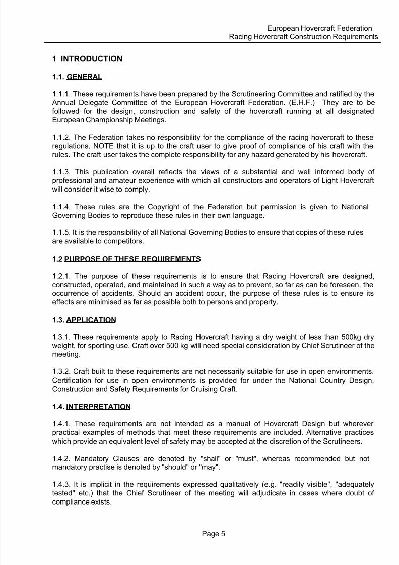
1 INTRODUCTION
1.1. GENERAL
1.1.1. These requirements have been prepared by the Scrutineering Committee and ratified by the Annual Delegate Committee of the European Hovercraft Federation. (E.H.F.) They are to be
followed for the design, construction and safety of the hovercraft running at all designatedEuropean Championship Meetings.
1.1.2. The Federation takes no responsibility for the compliance of the racing hovercraft to theseregulations. NOTE that it is up to the craft user to give proof of compliance of his craft with therules. The craft user takes the complete responsibility for any hazard generated by his hovercraft.
1.1.3. This publication overall reflects the views of a substantial and well informed body of
professional and amateur experience with which all constructors and operators of Light Hovercraftwill consider it wise to comply.
1.1.4. These rules are the Copyright of the Federation but permission is given to NationalGoverning Bodies to reproduce these rules in their own language.
1.1.5. It is the responsibility of all National Governing Bodies to ensure that copies of these rules
are available to competitors.
1.2 PURPOSE OF THESE REQUIREMENTS
1.2.1. The purpose of these requirements is to ensure that Racing Hovercraft are designed,
constructed, operated, and maintained in such a way as to prevent, so far as can be foreseen, the
occurrence of accidents. Should an accident occur, the purpose of these rules is to ensure itseffects are minimised as far as possible both to persons and property.
1.3. APPLICATION
1.3.1. These requirements apply to Racing Hovercraft having a dry weight of less than 500kg dryweight, for sporting use. Craft over 500 kg will need special consideration by Chief Scrutineer of themeeting.
1.3.2. Craft built to these requirements are not necessarily suitable for use in open environments.Certification for use in open environments is provided for under the National Country Design,
Construction and Safety Requirements for Cruising Craft.
1.4. INTERPRETATION
1.4.1. These requirements are not intended as a manual of Hovercraft Design but wherever
practical examples of methods that meet these requirements are included. Alternative practices
which provide an equivalent level of safety may be accepted at the discretion of the Scrutineers.
1.4.2. Mandatory Clauses are denoted by "shall" or "must", whereas recommended but notmandatory practise is denoted by "should" or "may".
1.4.3. It is implicit in the requirements expressed qualitatively (e.g. "readily visible", "adequately
tested" etc.) that the Chief Scrutineer of the meeting will adjudicate in cases where doubt ofcompliance exists.

8/11/2019 Construction Regs
http://slidepdf.com/reader/full/construction-regs 6/21
European Hovercraft FederationRacing Hovercraft Construction Requirements
Page 6
1.5. OPERATION OF THE REQUIREMENTS
1.5.1. These rules are brought into operation by the body of National Hoverclubs affiliated to the
E.H.F. Scrutineers. They are responsible for inspection of craft in order to issue a log book orcertificate, and for subsequent inspection at National Hoverclub organised events, or at the request
of an owner.
1.5.2. Where a craft owner operates his craft alone (outside organised events) it is his ownresponsibility to inspect his craft for compliance with these rules. Failure to maintain compliance
invalidates the Log Book or Certificate for the period of non-compliance.
1.5.3. The E.H.F. reserves the right to amend any regulation herein in the light of practicalapplication. Amendments to these rules will come in to force immediately following sanction by theE.H.F. council, and the new issue of these official E.H.F. set of rules.
1.5.4. The E.H.F. may grant special exemption from these rules to "Historic Craft", for purposes tobe defined, and in conditions to be defined by the Scrutineering Committee for each case.
1.6. APPEALS
1.6.1. In the case of an operator disagreeing with the ruling of a Scrutineer or the Chief Scrutineerof the meeting as adjudicator, he or she may appeal as follows:
a) Submit a complaint in writing to the Chief Scrutineer of the meeting and the EHF Secretarywithin one week of the incident.
b) Lodge a deposit defined in fees list with the E.H.F. (no action will be taken unless this deposit is
lodged, and cleared through a bank if paid by cheque).
1.6.2. The appeal will be considered by a Scrutineering Committee of the E.H.F. at its next
scheduled meeting, or one specially convened. Both complainant and Scrutineer will be expected
to attend this meeting. The Committee will judge the case, taking whatever additional technical orlegal advice is considered necessary.
1.6.3. A final appeal can be made to the Governing Board of the E.H.F. who’s decision will be final.
1.6.4. In the case that legal or other professional advice need be taken, the cost of suchadvice will be required to be paid by the complainant, whatever the outcome of the dispute.
1.7. METHOD OF COMPLIANCE
1.7.1. Compliance with these requirements shall be established by calculation, testing, or otherevidence to the satisfaction of the Scrutineer. An example of "other evidence" may be a certificateof compliance from a E.H.F. approved component manufacturer.
1.7.2. Where an applicant proposes to use a proprietary component in a manner other than that
provided for in its manufacturers certificate, then compliance shall be demonstrated to the E.H.F. orits agents.
8/11/2019 Construction Regs
http://slidepdf.com/reader/full/construction-regs 7/21
European Hovercraft FederationRacing Hovercraft Construction Requirements
Page 7
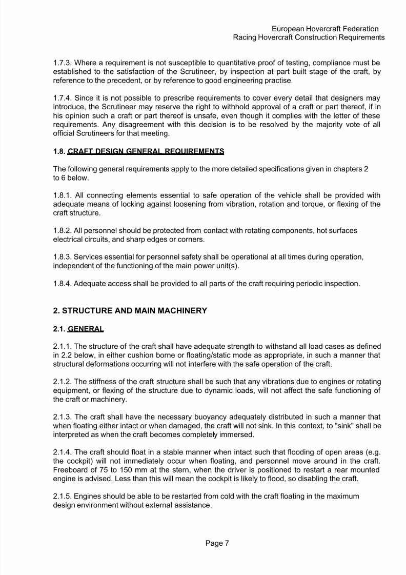
1.7.3. Where a requirement is not susceptible to quantitative proof of testing, compliance must beestablished to the satisfaction of the Scrutineer, by inspection at part built stage of the craft, by
reference to the precedent, or by reference to good engineering practise.
1.7.4. Since it is not possible to prescribe requirements to cover every detail that designers mayintroduce, the Scrutineer may reserve the right to withhold approval of a craft or part thereof, if in
his opinion such a craft or part thereof is unsafe, even though it complies with the letter of theserequirements. Any disagreement with this decision is to be resolved by the majority vote of allofficial Scrutineers for that meeting.
1.8. CRAFT DESIGN GENERAL REQUIREMENTS
The following general requirements apply to the more detailed specifications given in chapters 2
to 6 below.
1.8.1. All connecting elements essential to safe operation of the vehicle shall be provided with
adequate means of locking against loosening from vibration, rotation and torque, or flexing of thecraft structure.
1.8.2. All personnel should be protected from contact with rotating components, hot surfaceselectrical circuits, and sharp edges or corners.
1.8.3. Services essential for personnel safety shall be operational at all times during operation,
independent of the functioning of the main power unit(s).
1.8.4. Adequate access shall be provided to all parts of the craft requiring periodic inspection.
2. STRUCTURE AND MAIN MACHINERY
2.1. GENERAL
2.1.1. The structure of the craft shall have adequate strength to withstand all load cases as definedin 2.2 below, in either cushion borne or floating/static mode as appropriate, in such a manner that
structural deformations occurring will not interfere with the safe operation of the craft.
2.1.2. The stiffness of the craft structure shall be such that any vibrations due to engines or rotating
equipment, or flexing of the structure due to dynamic loads, will not affect the safe functioning of
the craft or machinery.
2.1.3. The craft shall have the necessary buoyancy adequately distributed in such a manner that
when floating either intact or when damaged, the craft will not sink. In this context, to "sink" shall beinterpreted as when the craft becomes completely immersed.
2.1.4. The craft should float in a stable manner when intact such that flooding of open areas (e.g.
the cockpit) will not immediately occur when floating, and personnel move around in the craft.
Freeboard of 75 to 150 mm at the stern, when the driver is positioned to restart a rear mountedengine is advised. Less than this will mean the cockpit is likely to flood, so disabling the craft.
2.1.5. Engines should be able to be restarted from cold with the craft floating in the maximum
design environment without external assistance.

8/11/2019 Construction Regs
http://slidepdf.com/reader/full/construction-regs 8/21
European Hovercraft FederationRacing Hovercraft Construction Requirements
Page 8
2.2. STRENGTH AND STIFFNESS OF STRUCTURE
2.2.1. The structure of the craft should have adequate strength to withstand loads encountered
under all conditions of operation. Load cases which should be considered by the designer are:
1) Manoeuvring: forces applied to controls and machinery frame.2) Floating: forces applied to the hull.3) Water impact: forces applied to the front or side planing surfaces of the hull.4) Transition: forces due to craft dropping over a step.5) Wind loads: forces applied to the structure.
6) Impact: forces due to skid stop over land.7) Parking: forces due to three point random support on the craft bottom.8) Towing: forces due to towing equal to twice craft weight.9) Machinery: forces on machinery mounts due to mass, torque and dynamic loads.
10) Collision: forces due to collision with an immovable object.
2.2.2. COMPLIANCE with 2.2.1. may be proved by inspection and possibly trials carried out by a
E.H.F. Scrutineer.
2.2.3. Inflatable structures forming a part or whole of the hovercraft primary structure shall
conform to Standard of the country where the craft is built.
2.3. CRASH WORTHYNESS
2.3.1. All major components and items of equipment shall be attached to the craft primarystructure with arrangements sufficient to withstand inertia forces of magnitude 5g (5 * component
weight) in any direction.
2.3.2. Machinery and frame mountings shall be fail safe by mounting design, or by secondaryrestraint.
2.3.3. A roll bar of adequate strength shall be built into all craft. This may take the form of structuralmembers primarily designed for other purposes(engines mounts etc...) if they will maintainadequate clearance for the occupants when the craft is inverted.
2.3.4. Interior surfaces and edges of structural members within the cockpit and cabin areas shall bedesigned to minimise injury to occupants in the event of a collision, by protection with
deformable or crushable padding. Guarding shall be provided to prevent limbs being trapped in
engine frames, structural members or exhaust systems.
2.3.5. The exterior periphery and underside of the craft shall be constructed so that any sharpedges or corners are protected by crushable material.
2.3.6. No components such as handling points, towing eyes, exhaust pipes, etc..., shall overhangthe hull structure, with the exception of aerodynamic control services.
2.3.7. Removable items such as batteries, fuel tanks, fire extinguishers, etc, shall remain securely
in position even if the craft is inverted.

8/11/2019 Construction Regs
http://slidepdf.com/reader/full/construction-regs 9/21
European Hovercraft FederationRacing Hovercraft Construction Requirements
Page 9
2.4. BUOYANCY AND STABILITY
2.4.1. Craft intended to be operated over water should be capable of floating in a reasonable
attitude in the event of loss of cushion lift, with the crew aboard, either to allow the craft to berestarted, or until the crew can be rescued if the craft becomes flooded.
2.4.2. The units of buoyancy shall be so located in the craft as to provide adequate stability when
the craft is water borne.
2.4.3. Consideration shall be given to the provision of adequate boyancy and stability of the craft.
Boyancy located in lower part of the hull is likely to sustain dammage when crafts plow in or crash.
2.4.4. Buoyancy sufficient to keep the craft afloat when swamped with water shall be provided by
non absorbent foam, inspectable air bags, or multi cellular inspectable boxes.
2.4.5. Temporary additional external buoyancy may have to be added onto the hull for meetings on
rivers or at the coast.
2.4.6. Designers are advised to add a design margin to the weight used to design the buoyancy,
and to be careful to account for the fact that the effective buoyancy of foam filled compartments isreduced by the weight of the foam that is added to the craft. It is further advised that retrieval of a
craft with a flooded cockpit using a tow rope is much easier and safer if it floats level. Buoyancyshould be placed in such a manner therefore, that the propulsion system, or any other majorcomponents above the line of the top of the craft hull are supported in air. This will generally require
about 2/3 of the total craft buoyancy to be sited in the rear half of the craft length.
2.4.7. Special note should be taken of designs having internal air ducting to segmented skirts. Any
ducting areas extending below the waterline need to be designed to allow water to be removedwhen hovering up.
2.4.8. INTACT STABILITY. The intact floating stability of the craft should be such that when floatingin calm water, the crew are able to move about the craft within reasonable limits, and to restart the
engine(s) without flooding the cockpit. The placing of buoyancy as in 2.4.6. above should thereforetake account of the weight of the driver in the pull starting position.
2.4.9. DAMAGED STABILITY. The craft shall not sink in the case of the cockpit being flooded due
to an accident. The flooded craft shall retain sufficient residual buoyancy to allow the crew to hold
onto it while floating in the water supported by their lifejackets.
2.4.10. HULL OUTER SURFACE CONFIGURATION. The outer surface of the hull shall be soconfigured as to provide a planing surface with a dihedral angle of 10 o to 35o in the case that the
skirt should totally collapse on one side, front, or rear of the craft, at maximum operating speed in
still air over land or water. The planing surface(s) shall be present over a depth not less than that
defined by the skirt outer and inner hull attachment points.
2.5. MAIN MACHINERY, MOUNTING AND TRANSMISSIONS
2.5.1. All components of machinery and transmissions shall be constructed, arranged within thecraft, and protected as necessary to ensure their safe functioning at all times. considered. In anysuch case, the system shall fail safe, and not endanger the crew.

8/11/2019 Construction Regs
http://slidepdf.com/reader/full/construction-regs 10/21
European Hovercraft FederationRacing Hovercraft Construction Requirements
Page 10
2.5.3. Mountings and connections between main machinery and primary structure and betweenmain machinery and rotating assemblies shall be positively locked. Such mountings andconnections shall be designed in order that failure of 25 % of the mountings or connections will not
lead to any subsequent failure, or endanger the safe operation of the craft.
2.5.4. Pipe work and hoses on water cooled engines shall be designed and installed in such a wayas to minimise the possibility of failure which may result in injury to the driver or bystander.
3. ROTATING ASSEMBLIES
3.1. DESIGN AND OPERATION
3.1.1. All rotating assemblies shall be designed and operated such as to preclude as far as possiblefailure during normal operating life of the assembly.
3.2. FANS
3.2.1. A number of proprietary fans are available and suitable for use on Light Hovercraft. Therotating speed of these fans is to be limited following the guide lines given in appendix B. EHF
approves the HCGB method of testing blades. Any blade approved by the HCGB will be allowed inEHF.
3.2.2. Propulsion systems designed for tip speeds in excess of 140 m/s are likely to produce noiselevels in excess of 87 dBA at 25m distance. A maximum design tip speed of 120 m/s isrecommended to be used for this reason where practical.
3.2.3. FAN SPEEDS FOR GIVEN DIAMETERS. A table given in Appendix B indicates fan r.p.m. for
the limiting tip speeds, based on the recommended limits of 120 m/s for normal operation, 140 m/sfor design maximum, and 170 m/s which is the absolute limit for Moulting Z and Nylon blade fansand Breeze a plus blades.
3.3. PROPELLERS
3.3.1. Wherever possible it is recommended that reliable commercial units (with a test certificate)are used. If it is essential to home produce a propeller or fan, the material should be very carefullyselected, and if possible tested for tensile strength. Wooden blades shall be laminated. It is very
important to provide adequate blade cross section in the region of the blade root. Glass Fibre isunreliable for propellers - even when laid up under carefully controlled conditions - and should be
avoided. On no account shall cast materials (aluminium, resin, etc...) be used. If accuratematerials and stressing data is not provided, then maximum permissible tip speed shall be 140
m/sec for normal operation.
3.3.2. Every prototype propeller should comply with the "prototype propulsions guide lines" given in Appendix B.
3.4. OVERSPEED CONDITIONS
3.4.1. The normal operating rotational speed for craft with more than one fan unit driven from asingle engine must allow for the overspeed of the remaining unit(s) resulting from a single failure in
the transmission system. The limiting stress in rotating assemblies shall not exceed 0.66 x the
material design stress for the overspend conditions as follows:

8/11/2019 Construction Regs
http://slidepdf.com/reader/full/construction-regs 11/21
European Hovercraft FederationRacing Hovercraft Construction Requirements
Page 11
Failure Overspeed
1 from 2 30%
1 from 3 15%
2 from 3 50%
Overspeed Conditions
3.5. POSITIVE LOCKING OF FASTENINGS
3.5.1. Inspectable positive locking devices (wire, split pins, nylon nuts) will be employed in the
rotating assembly and its mounting structure, where loosening might cause a dangerous
misalignment. Adhesive (Loctite or Casio ML or equivalent) will not normally be deemedadequate.
3.6. GUARDING OF ROTATING ASSEMBLIES
3.6.1. All rotating assemblies shall be guarded in such a way that under all operating conditions nopart of a person or his clothing may enter the space swept by the rotating assembly, or force theguards or the duct structure into that space whether the person be:
(a) in collision with...or (b) manhandling....
or (c) operating......the hovercraft.
3.6.2. A fail-safe device shall be fitted to all transmission shafts transmitting more than 15 kW per
shaft, in order to prevent shaft "flailing" in consequence of bearing or bearing housing failure.
Suitable flail guard devices include a suitably sized metal strap over pedestal bearing housings orsuitably sized plates with a clearance hole around the shaft to act as temporary plain bearing, and
limit shaft movement. Such flail guards should be securely attached to a substantial part of thetransmission mounting frame in order that the shaft movement will not cause failure in the guard
itself.
3.6.3. MINIMUM GUARDED AREA.
Fans and propellers must have guards at the intake, around the periphery and at the dischargeside of the unit, to the following standards:
1. The INLET SIDE of all fans or propellers must be guarded to the standard of 3.6.4. and 3.6.5.
below.
2. The PERIPHERY of the volume swept by the fan or propeller must be surrounded by a guardextending at least 125 mm(5 inches) forward and 250 mm(10 inches) aft of the swept volume, to
avoid fingers gripping the edge of the guard from contacting the blades.
3. Special care shall be taken to provide adequate guarding at the exit area from a fan or propeller.
There shall be no open areas greater than 300 mm diameter(12 inches) at a position
250mm aft of the fan or propeller swept volume. Guarding may be provided in the form of rudder(s),elevator(s), duct support framework, fan centre bodies or flow straightener vanes, or wire mesh
conforming to the strength requirements of 3.6.5. below.4. All rotating shafts, transmission belts, chains or gears shall be guarded by containment inside a
closed space (engine compartment, fan centre body, engine or component solid cover) or by wire
mesh guarding to the requirements of 3.6.5. below.

8/11/2019 Construction Regs
http://slidepdf.com/reader/full/construction-regs 12/21
European Hovercraft FederationRacing Hovercraft Construction Requirements
Page 12
5. No guard shall extend beyond the edge of the main hull structure. Local extensions to the hullshall not be considered part of the craft main hull.
6. Quick release (Insuloid etc.) guard clips shall be mounted at intervals of no more than 300 mm
around the periphery of each guard.
3.6.4. GUARD MATERIAL AND CONFIGURATION.
Guarding may be provided in the form of wire mesh, wire rod, tubular metal framing, and solid wallducting. Where wire mesh is used to make a guard, the following mess sizes shall be the maximum
acceptable:
Distance from
Device Swept Volume
Maximum Mesh
Dimension
125 - 150 mm (6 in) 12 mm (0.5 in)
< 800 mm (32 in) 50 mm (2.0 in)
> 800 mm (32 in) 300 mm (12.0 in)
Minimum MeshSizes
3.6.5.GUARD OVERALL STRENGTH AND RIGIDITY
No guard or structure shall deflect into the swept volume of the rotating device when a force of50daN (50kg) is applied over an area of 1 cm at any point of the guard. This is to prevent failure of
the rotor, or injury to a third party in the case of a man falling onto the guard and taking the impact
on one hand.
3.6.6. CONTAINMENT OF FAILED BLADES
1. All fan and propeller guarding shall be designed to contain so far as is possible, failed blades or
blade pieces caused by collision or ingestion of foreign objects.
2. FANS - Polypropylene blade materials tend to break into many pieces while Nylon or Delrinblades tend to fail at the blade root or into larger pieces. Minimum thickness of G.R.P. ducting over
an area 100 mm forward and aft of the centreline of the rotor swept volume shall be 4 layers2
of 450 g/m chopped strand mat for maximum tip speed of 140 m/s. Where tip speed is > 140 m/s2
duct reinforcement shall be added to by 2 x 450 g/m layers chopped strand mat (CSM). The
addition of stronger materials such as woven rovings, Kevlar or wire mesh within the laminate ishighly recommended.
3. DUCTED PROPELLERS - Where propellers are guarded by a duct system with mesh guardingat the inlet, the duct shall have metal plate or heavy gauge wire mesh reinforcement over an area
100 mm both forward and aft of the propeller swept volume. The reinforced duct shall be of
sufficient strength to contain a blade component in the manner and condition of item 4. below. Theduct outlet may require mesh guarding to contain a blade component as in item 4. below.
4. PROPELLERS WITH MESH GUARDS - Where guarded by wire and tube mesh cage(s), the
propellers shall be guarded by mesh to the sizes as in 3.6.4. above. The guard shall be of
sufficient strength to contain a blade component comprising the outer two thirds of a single blade,o
ejected in any direction from directly ahead to 45 aft from the propeller swept disc at a rotationalspeed corresponding to the application of maximum engine power, plus a margin of 10 % of enginepower.

8/11/2019 Construction Regs
http://slidepdf.com/reader/full/construction-regs 13/21
European Hovercraft FederationRacing Hovercraft Construction Requirements
Page 13
5. FAILURE CONDITIONS - It should be noted that the requirements in items 1. to 4. above do NOTrequire that the guarding shall remain undamaged in failure conditions. The requirement is forcontainment of rotating components. Gross deformation of the guard structure is acceptable, thoughthe designer should bear in mind that in such a case the craft is likely to be disabled. In addition to the
guard fixings, it is required that four failsafe tethers should be attaced evenly around the periphery ofthe upper two/thirds of the guard. The tethers should allow a maximum of 20 mm travel of the guardfrom the duct.
3.7. TRANSMISSIONS
3.7.1. Machinery transmissions shall fulfil the requirements of chapter 2 above.
3.7.2. Transmission shafts of capacity greater than 15 KW shall be protected by flail guardssufficient to contain a failed shaft rotating as specified in 3.6.2. above, in addition to bearing
failures.
3.7.3. Transmission shaft linkages and support bearing mountings shall be positively locked to the
requirements of 3.5. above.
3.7.4. All transmission rotating components shall be guarded to the level of section 3.6. againstcontact with personnel.
4. SYSTEMS AND CONTROLS
4.1. GENERAL
4.1.1. This chapter specifically covers the following:
-Aerodynamic control surface systems-Engine, Transmission and associated controls-Fuel systems
-Electrical systems.
4.1.2. All systems and controls shall be designed to be safe in operation and where possible fail-
safe when released by the operator. Any systems and controls installed in a racing hovercraft whichare not specifically referred to here should be designed and constructed to this same principle.
Acceptance of such systems will be at the discretion of the National HoverclubScrutineering Committee.
4.1.3. The designer should keep in mind the environment in which the controls and systems willoperate. Where systems are likely to be sensitive to dampness, salt water, sand ingress,vibration, and relative movement of craft substructures, they should be rejected or designed for
protection against such effects.
4.2 AERODYNAMIC CONTROL SURFACES AND OPERATING SYSTEMS
4.2.1. Aerodynamic control surfaces may be of two types:
a) FIXED SURFACES providing aerodynamic stabilising forces while in operation, which are fixedor able to be moved (trimmed) when the craft is stopped such as fixed elevators, fins or fan
straightener vanes.

8/11/2019 Construction Regs
http://slidepdf.com/reader/full/construction-regs 14/21
European Hovercraft FederationRacing Hovercraft Construction Requirements
Page 14
b) MOVING SURFACES providing aerodynamic control forces, such as rudders, controllableelevators, or elevons.
4.2.2. Fixed surfaces shall be attached to the craft structure with arrangements sufficient tomaintain them securely in position under the maximum design airspeed over the device, at the
position of maximum control force generation.
4.2.3. Moving surfaces shall be attached to the craft structure with hinging arrangementssufficient to maintain them securely in position under the maximum design airspeed over thedevice, at the position of maximum control force generation.
4.3. ENGINE, TRANSMISSION AND PRIMARY CONTROLS
4.3.1. Craft with one main power plant shall have a throttle control which has a spring return to theengine idle position.
4.3.2. Craft with separate lift and propulsion power plant shall have spring return throttle(s) onpropulsion engine(s) to engine idle position.
4.3.3. All primary controls shall be capable of operation by the driver when in the normal driving
position, with sufficient ease, and smoothness of operation, to permit the proper performance of
their function.
4.3.4. Full movement of every control shall be possible when the driver is in place while wearing
appropriate protective clothing and safety equipment.
4.3.5. Manually operated control systems should be desighned with adequate saftey margin againstthe loads shown in the table below, applied with the maximum lever arm possible .
CONTROL LOAD
FOOT 600 N
STICK LEVER 500 N Fore and Aft and 300 N Lateral
WHEEL 500 N Fore and Aft and 200 N / meter Torqu e(200• D) D= Wheel Diameter
HANDELBAR 500 N Fore and Aft250 N in rotat ion
4.4. FUEL SYSTEMS
4.4.1. All tanks, containers, pipelines, structure and equipment shall be designed to comply with thestrength requirements of the vehicle as described in Chapter 2, and the fire safetyrequirements of Chapter 5.
4.4.2. Fuel tanks shall be fuel tight against the operating conditions of the craft whilst providing forfuel expansion due to temperature changes, prevent siphoning of fuel through vents, and
minimise entry of water through fillers. Fuel tanks shall be capable of drainage to completely empty
condition.
4.4.3. Fuel tanks and supply lines shall be so located that, in the event of a leak occurring, theescaping fuel is prevented, so far as possible, from making contact with any of the hot parts (e.g.
engine, exhaust pipe etc.), or electrical circuits of the craft.
8/11/2019 Construction Regs
http://slidepdf.com/reader/full/construction-regs 15/21
European Hovercraft FederationRacing Hovercraft Construction Requirements
Page 15
4.5. ELECTRICAL SYSTEMS
4.5.1. Electrical systems shall be so designed that their normal operation will not create a fire
hazard, and also that additional hazards will not be created in the event of a fire in a designated firezone.
4.5.2. It shall be possible for the driver of the craft to switch off engines and power to all electricalsystems while in the normal driving position. Switches must be of the positive-off type. Theelectrical cut off switch(es) shall be marked by an 80 mm red equilateral triangle, bounded by a
white border 10 mm wide, within triangle dimensions.
4.5.3. Battery power supplies should in addition have a separate circuit breaker in a clearly
accessible position outside any fire zone, and marked by an 80 mm sided RED equilateral triangle
bounded with a white border 10 mm wide, within the triangle dimensions, or an internationallightning strike sign.
4.5.4. Engines shall have a pull-out type lanyard ignition kill switch, the lanyard of which shall be
attached to the driver at all times during operation, so that in the case of an accident where thedriver is thrown out, the craft will be stopped. The operation of this lanyard switch will be regularlychecked by Scrutineers or Marshals as part of a pre-race checkout.
4.5.5. Engines shall have adequate Radio Frequency (RFC) / (EMC) suppression fitted, as requiredby common law in the E.E.C. It should be noted that RFC suppression relates particularly to ignition
systems, including spark plug leads and caps, and coils/condensers. Suppressed plug caps areavailable, as are low emission leads, or RFC chokes for leads, in most car parts stores.
A simple check of the effectiveness of RF suppression is to turn on a transistor radio in proximity to
the craft. If there is substantial interference, then the craft RF suppression is not adequate.
5. FIRE SAFETY
5.1. GENERAL
5.1.1. The design of craft shall be such as to minimise the risk of fire occurring.
5.1.2. Engine exhausts shall be designed so that no appreciable amount of gas can enter the aircushion system of a no-flow bag skirt. The exhaust outlet must be clear of the lift fan intake suctionon a no-flow bag skirt.
5.1.3. Craft designed with a substantially or totally enclosed cockpit shall be separated from the
engine or engines by flame resistant on non flammable bulkheads. Metal or metal clad bulkheadsare recommended.
5.2. FUEL TANKS
5.2.1. Fuel Tanks and supply lines will be constructed and mounted so that any vibration or
distortion of the craft structure during operation will not damage the tank, or cause leaks in thesupply line(s).
5.2.2. Gravity feed fuel tanks shall be fitted with a cut-off tap which can be easily operated by the
driver.
5.2.3. Fuel tanks with feed from the base of the tank shall be fitted with a cut-off tap, easilyoperable by the driver, so that if the fuel line fails, the tank can be stopped from draining out.
5.2.4. Fuel containment systems shall be so designed that liquid fuel cannot leak and directly

8/11/2019 Construction Regs
http://slidepdf.com/reader/full/construction-regs 16/21
European Hovercraft FederationRacing Hovercraft Construction Requirements
Page 16
contact any hot parts, or electrical components when the craft is inverted, or in any attitude suchthat fuel may leak from the vent or breather systems.
5.2.5. Fuel lines of PVC or other plastics which degrade over time shall be replaced annually.
5.3. HOT PARTS
5.3.1. The parts of a craft within 50 mm from hot parts, for example engine exhaust pipes orsilencers, shall be of non-flammable or fire inhibiting material.
5.3.2. Hot parts shall have an adequate supply of cooling water or air to maintain a steady designtemperature during all normal operations.
5.3.3. Exposed hot exhaust pipes or silencers shall be protected by a stand-off wire mesh guard orthermal lagging if mounted in locations close to the driver or normal craft manhandling points.
6. SKIRT DESIGN AND ATTACHMENT
6.1. STABILITY
The skirt system as fitted to the craft should be such as to ensure adequate stability when hovering
under all possible operating conditions. Adequate stability is defined as follows :
6.1.1. For the craft trimmed level in a static hovering condition, the skirt shall provide sufficientrighting moments in the conditions of maximum design speed, and maximum design environmentof wind and waves or hard surface, so as to prevent plough-in during application of a moment equal
to transfer of 10 % payload fore and aft or cross the beam of the craft the maximum distance
feasible for the craft design.
6.1.2. The righting moment generated by the skirt system in pitch and roll shall steadily increase ata linear or greater rate with rotation, to the point that the hull contacts ground or water.
6.1.3. The skirt system shall be intrinsically stable in heave (vertical motions) at any power setting.
6.2. CONSTRUCTION AND MATERIALS
6.2.1. Skirt material should be coated, woven material with high resistance to ripping in any
direction.
6.2.2. Attachments of the skirt to the hull shall be of sufficient strength that no damage is caused to
the hull attachment if the skirt material is ripped or snagged with sufficient force to break the skirtconnecting device.
6.2.3. Attention should be paid to the configuration of seams on a bag or loop so that rips will be
stopped by the seams, rather than guided by them.
6.3. DAMAGE
6.3.1. The craft should maintain stability sufficient to prevent capsize in the event that any part of
the skirt should collapse and be dragged back by the water surface during operation at maximum
operational speed in any direction.

8/11/2019 Construction Regs
http://slidepdf.com/reader/full/construction-regs 17/21
European Hovercraft FederationRacing Hovercraft Construction Requirements
Page 17
6.3.2. The skirt should be designed so that damage to any part or area of the skirt will not causeother parts or areas of the skirt to fail as a direct consequence.
7. HANDLING, PERFORMANCE AND OPERATIONAL SAFETY
7.1. GENERAL
7.1.1. The general principles of operational safety for a racing light hovercraft shall be that in the
event of an accident, the driver shall be provided with reasonable means of escape and survival.
7.2. DEMONSTRATION OF CHARACTERISTICS
7.2.1. The National Governing Body organising the event reserve the right to call for a trial
demonstration of craft characteristics of buoyancy, freeboard, stability, adequate control,emergency stopping, and safe performance.
7.3. ARRANGEMENTS FOR OPERATIONAL SAFETY
7.3.1. Crash Helmets to Drivers National Standard or better, MUST be worn by the driver
whenever the craft is operated.
7.3.2. A buoyancy aid to Drivers National Standard or a life jacket (with at least inherent buoyancy
to the National Standard specification) must be worn when a craft is operated over water.
7.3.3. The driver must wear suitable protective clothing covering arms, legs and torso and hands.
7.3.4. The driver should have adequate all round vision directly, or by other means.
7.3.5. All craft shall be fitted with handling points adequate for manhandling of the craft itself, and
for grasping by personnel overboard. The handling points shall be handles designed for grasping,not cleats.
7.3.6. Handles shall be a minimum of two on either side.
7.3.7. Craft should be fitted with a towing eye and permanently attached towing rope at the bow ofsufficient strength to pull the waterlogged craft ashore. The fitted rope shall be at least 5 meters
long (7 to 10 meters if possible), with a floating loop at the free end, the other end securely fixed to
the craft. The rope breaking strength is not to be less than 2000 N.
7.4. EXTERNAL AND INTERNAL NOISE LEVEL
7.4.1. The external noise level is measured at a distance of 25 meters and a height of 1.2 m aboveflat, open grass land. The limit is set by the racing comitee and is stated in the racing regulations (
§ 17.0 A)
It may be noted that background noise in most outdoor environments generally only varies within
3 dBA, and noise meters are generally accurate to within 0.5 dBA. Craft registering greater thanthe limit during a meeting check carried out by a National Hoverclub designated official willtherefore be deemed excessively noisy and forced to undergo a static noise test or be stopped fromfurther racing until a further check proves the craft to be within the regulation, at the discretion of
the Meeting Organiser.

8/11/2019 Construction Regs
http://slidepdf.com/reader/full/construction-regs 18/21
European Hovercraft FederationRacing Hovercraft Construction Requirements
Page 18
7.4.2. The internal noise level at the driver's normal head position should not be greater than 105
dBA. Levels higher than this can cause permanent hearing loss. It is recommended that the noiselevel at driver's head be kept below 100 dBA if at all possible, for comfort reasons.
7.4.3. Craft exceeding a static noise level set by the competition regulations (§ 17.0 B) may at therace directors discretion be banned from further operation, unless further checks show remedialaction has been taken. Static noise measurements will be made at a distance of 25 meters from thecraft with the instrument set 1.2 meters above the ground. The craft will be opperated in a fixedposition with all engines at maximum revs. Measurements will be taken at various angels arroundthe craft.
8. CRAFT CERTIFICATION
8.1. GENERAL
8.1.1. A Light Hovercraft for racing use may be certified by the issue of a Log Book or Certificate ofCompliance, following inspection by a National Hoverclub Scrutineer, the execution of such trials as
are considered necessary, and provision of such appropriate design documentation as may berequested by the certification Scrutineer.
8.1.2. Where special materials or methods are to be used in the craft design or construction, priorconsultation with the Scrutineering committee, through the chairman, is strongly recommended, toensure that such will be acceptable.
8.2. CERTIFICATES AND LOG BOOKS
8.2.1. Issue of a Log Book or Certificate of compliance constitutes a declaration by the NationalHoverclub that it is satisfied that the design and construction of the craft concerned, at the time of
inspection, gives rise to an acceptance level of safety for the purpose of issuing a Log Book orCertificate.
8.2.2. The operator of a craft which has a Log Book or Certificate may be required to carry out themaintenance schedule approved for the craft by the National Hoverclub.
8.2.3. Scrutineers are authorised to prevent further operation and withdraw the Log Book orCertificate if in their opinion the craft is no longer safe.
8.3. REGISTRATION
8.3.1. The craft registration number shall be clearly displayed on the craft hull using numerals not
less than 50 mm in height.
8.3.2. The craft shall clearly display a Racing Number designated by the National Hoverclub andissued to the craft driver in letters not less than 250 mm high and 25 mm thick in positions such that
the number is visible from either side. The recommended position is on the sides of the thrust duct
or ducts.

8/11/2019 Construction Regs
http://slidepdf.com/reader/full/construction-regs 19/21
European Hovercraft FederationRacing Hovercraft Construction Requirements
Page 19
APPENDIX A -- TYPICAL DESIGN LIMITS AND MARGINS
A.1. GENERAL
A.1.1. Design of a hovercraft will involve estimating the weights of various components in order todetermine the loads applied to the structure, and then estimating the local pressures at support
points, or the buoyancy distribution of the floating craft.
A.1.2. It is important to remember to apply a factor of 1.1 to all major masses during the design
process. When estimating buoyancy it is advisable to use water density of 1.0 g/cc (fresh water),and be careful not to overestimate the buoyancy volume of the craft, as freeboard is also definedby the buoyancy.
A.1.3. When considering the craft standing on three points, the local pressure applied by this case
will probably determine the required floor thickness. A rule of thumb which may be applied for craftwithin these rules, of typical hull geometry currently used would be minimum thickness 6 mm for
plywood bottom, 3 mm for GRP and approximately 1.5 mm (16 SWG) for aluminium. Suchthickness will avoid punching holes in the bottom. It should be noted that the use of dish typelanding pads, landing strakes, or runners (stiffeners or GRP D rope) will both stiffen the floor paneland help further prevent punching damage.
A.1.4. If the craft floor is a sandwich construction with buoyancy foam between two panels then thelower panel should be as in the previous paragraph. The two panels should be connected with
webs sufficient to transfer the load from the driver or passenger's feet, since otherwise the foam willcrush, and the mechanical connection be lost.
A.2. MATERIAL STRESSES
A.2.1. Typical properties of materials which may be used for hovercraft design values are as follow:
Material Tensile Stress(daN/mm)
Shear Stress(daN/mm)
Aluminium GP30 11.0 17.5
GRP (csm) 3.5 17.0
Plywood 1.4 11.7
A.2.2. These values are for guidance only. They are appropriate design values for non fatigue type
stresses. Where there is vibration and so fatigue, then the material strength above should bedivided by 2.2 to give a design value for steel and aluminium, and divided by 4.0 for GRP orplywood. National Standards Office give detailed specifications for all these materials, and
designers will find comprehensive data in National Standards Office documents. Further advice on
application to specific designs may be given by National Country Scrutineers on request.

8/11/2019 Construction Regs
http://slidepdf.com/reader/full/construction-regs 20/21
European Hovercraft FederationRacing Hovercraft Construction Requirements
Page 20
APPENDIX B -- THRUST SYSTEMS
B.1. GENERAL
B.1.1. For the purposes of Scrutineering it is irrelevant what the propulsion system is called as long
as it is safely constructed. So in conjunction with existing guide lines on plastic fans, it is agreed tocollate the required information to homologate laminated wooden propulsors.
B.2. HOMOLOGATED PLASTIC FANS
B.2.1. A number of proprietary fans are available and suitable for use on Light Hovercraft. The use
of these fans is to be limited to a combination of rotational speed and diameter giving blade tipspeed less than the following:
Type of Fan Blade Max Tip Speed
Multiwing Type 2 (Polypropylene Blades) 137 m/s
Multiwing Type 3 (Polypropylene Blades) 137 m/s
Multiwing Type 6 (Polypropylene Blades) 137 m/s
London Fan Co. ("Breeza") (Black) 168 m/s
Multiwing Type 2 (Glass filled Nylon Blades) 168 m/s
Multiwing Type 3 (Glass filled Nylon Blades) 168 m/s
Multiwing Type 4Z (Glass filled Nylon Blades) 168 m/s
Multiwing Type 5Z (Glass filled Nylon Blades) 168 m/s
Multiwing Type 7X (Glass filled Nylon Blades) 168 m/s
Centrifugal Fans note 1) 85 m/s
Hasconwing Type L,M,B (Glass filled Nylon Blades) 168 m/s
Hasconwing Type L,M,B (Polypropylene Blades) 168 m/s
Trueflow (Polypropylene Blades) 137 m/s
Typical Fan Speeds
Note 1: Centrifugal fans should not be run at speeds exceeding manufacturers recommended design value,but in any case should not exceed the values above.
Note 2: The use of "Truflo" axial fans with pressed steel hubs and nylon blades is expressly forbidden uponRacing Craft, as from 01.03.87. The use of Truflo fan blades with other than pressed steel hubs may beconsidered by the Scrutineering Committee by application through the Chairman.
(*) Centrifugal fans should not be run at speeds exceeding manufacturers recommended designvalue, but in any case should not exceed the values above.
B.2.2. The duct shall comply to rotating assemblies protection rules.
B.2.3. The guard shall comply to rotating assemblies protection rules.
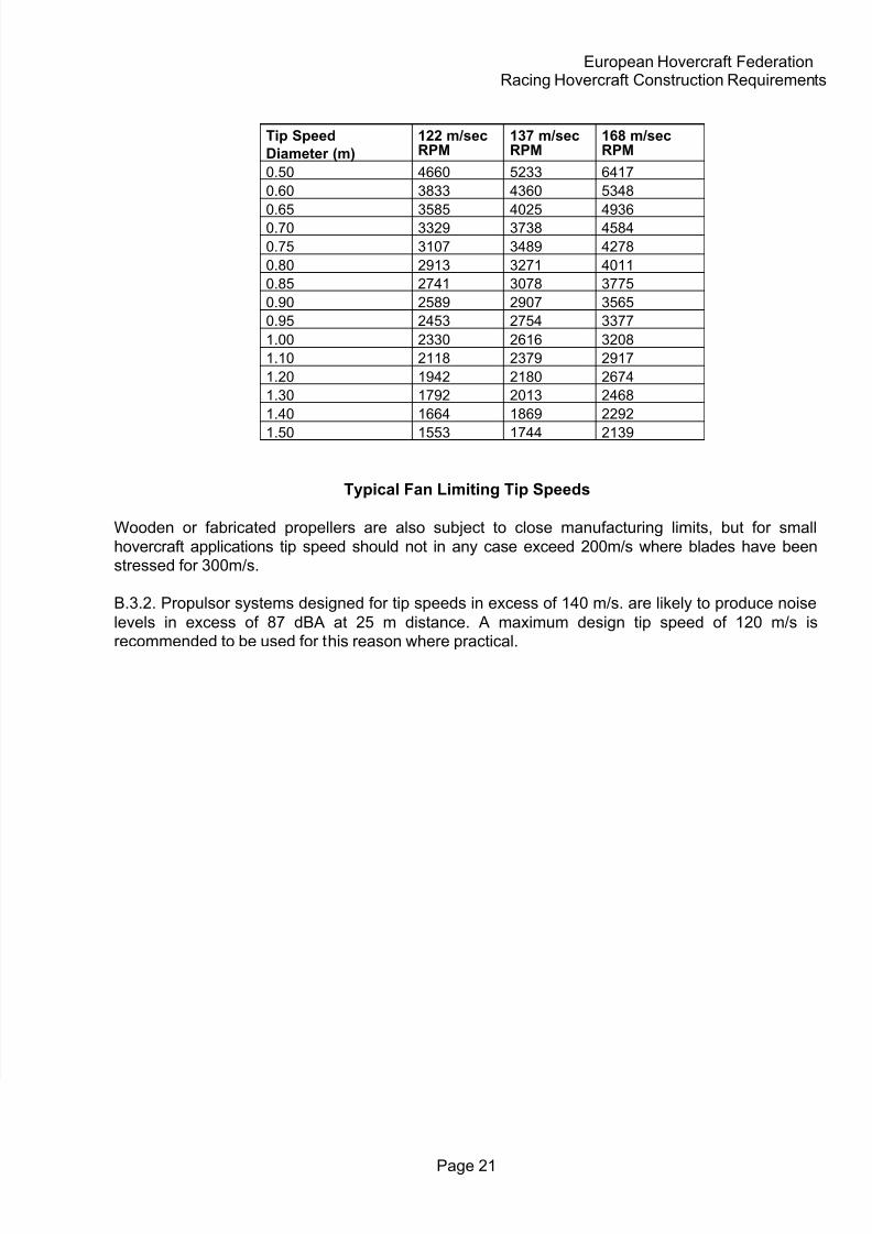
B.3. FAN SPEEDS FOR GIVEN DIAMETERS
B.3.1. The table below indicates fan r.p.m. N for the limiting tip speeds U, based on therecommended limits of 120 m/s for normal operation, 140 m/s for design maximum, and 170 m/s
which is the absolute limit for Multiwing Z and Nylon blade fans and Breeza plus blades.
8/11/2019 Construction Regs
http://slidepdf.com/reader/full/construction-regs 21/21
European Hovercraft FederationRacing Hovercraft Construction Requirements
Tip Speed
Diameter (m)
122 m/secRPM
137 m/secRPM
168 m/secRPM
0.50 4660 5233 6417
0.60 3833 4360 5348
0.65 3585 4025 49360.70 3329 3738 4584
0.75 3107 3489 4278
0.80 2913 3271 4011
0.85 2741 3078 3775
0.90 2589 2907 3565
0.95 2453 2754 3377
1.00 2330 2616 3208
1.10 2118 2379 2917
1.20 1942 2180 2674
1.30 1792 2013 2468
1.40 1664 1869 2292
1.50 1553 1744 2139
Typical Fan Limiting Tip Speeds
Wooden or fabricated propellers are also subject to close manufacturing limits, but for small
hovercraft applications tip speed should not in any case exceed 200m/s where blades have beenstressed for 300m/s.
B.3.2. Propulsor systems designed for tip speeds in excess of 140 m/s. are likely to produce noise
levels in excess of 87 dBA at 25 m distance. A maximum design tip speed of 120 m/s is
recommended to be used for this reason where practical.