containex plus line technical description
TRANSCRIPT

CONTAINEX PLUS Line
Technical Description

2 (23) / 2021/06
Content
Abbreviations ................................................................................................................. 4
General ..................................................................................................................... 4
Dimensions and weights .............................................................................................. 4
Assumed load .............................................................................................................. 5
1.2.1 Snow loads ........................................................................................................................... 5
1.2.2 Wind loads ............................................................................................................................ 5
1.2.3 Floor payloads ...................................................................................................................... 5
1.2.4 Basic principles of the static calculations ............................................................................. 6
Insulation ...................................................................................................................... 6
Container design ..................................................................................................... 7
Frame construction....................................................................................................... 7
Floor structure .............................................................................................................. 7
Roof structure ............................................................................................................... 8
Wall panels .............................................................................................................. 9
Doors ........................................................................................................................... 9
3.1.1 External door "Thermo65" .................................................................................................... 9
3.1.2 Steel doors .......................................................................................................................... 10
Window ...................................................................................................................... 10
Glazing ....................................................................................................................... 11
Partition walls ............................................................................................................. 12
Fire resistance ....................................................................................................... 13
Electrical installations .......................................................................................... 13
Technical data ............................................................................................................ 13
Heating and air conditioning ....................................................................................... 16
Design options ...................................................................................................... 16
Water installations ................................................................................................ 17
Paint ....................................................................................................................... 17
Certifications ......................................................................................................... 17
Miscellaneous ....................................................................................................... 18
Layout possibilities ..................................................................................................... 18
Transport .................................................................................................................... 19
Handling ..................................................................................................................... 19
Installation / Assembly / Statics / Maintenance ........................................................... 20

3 (23) / 2021/06
Support points ................................................................................................... 21
Support points BP / SP 10', 16' and 20' ....................................................................... 21
Support points BP / SP 24' ......................................................................................... 21
Support points corridor cabin GP 16' and 24'.............................................................. 22
Support points 3P20 and 4P20 ................................................................................... 22
Support points internal staircase cabin TP20.............................................................. 23

4 (23) / 2021/06
Abbreviations
The following abbreviations are used in the document:
Portable cabin PLUS Line BP
Sanitary cabin PLUS Line SP
Corridor cabin PLUS Line GP
Portable cabin PLUS Line 20'x10'* 3P20
Sanitary cabin PLUS Line 20ʹ x10ʹ* 4P20
Internal staircase cabin PLUS Line 20ʹx10ʹ TP20
* only available in a modular building in combination with an internal staircase cabin TP20
Polyisocyanurate PIR
Polyurethane PU
Internal height RIH
External cabin height CAH
Toughened safety glass ESG
Laminated safety glass VSG
General
Dimensions and weights
Type external
[mm]
internal
[mm]
Weight
[kg]
Length Width Height Length Width Height (approx.
specifications)
10ʹ 2,989 2,435 3,100 2,749 2,195 2,550 1,500
16ʹ 4,885 2,435 3,100 4,645 2,195 2,550 2,400
20ʹ 6,055 2,435 3,100 5,815 2,195 2,550 2,900
24ʹ 7,335 2,435 3,100 7,095 2,195 2,550 3,500
20ʹx10ʹ 6,055 2,989 3,100 5,815 2,749 2,550 3,500

5 (23) / 2021/06
Assumed load
1.2.1 Snow loads
Characteristic snow load on the floor
sk = 2,50 kN/m² (250 kg/m²) Shape parameters µ=0,8 ( s = µ1 * sk = 2,0 (kN/m² (200 kg/m²))
1.2.2 Wind loads
Wind load vref = 27,5 m/s, (100 km/h) terrain category III
At wind speeds of more than than 27.5 m/s (100 km/h) additional securing of the cabins must be
carried out (anchoring, screwing, etc.). Such measurements are to be calculated by approved
specialists taking into consideration local standards and conditions.
1.2.3 Floor payloads
1.2.3.1 Payloads for BP / SP 10', 16' and 20'
Ground floor: max. load capacity 4,0 kN/m² (400 kg/m²)
Top floors: max. load capacity 3,0 kN/m² (300 kg/m²)
1.2.3.2 Payloads for BP / SP 24'
Ground floor: max. load capacity 4,0 kN/m² (400 kg/m²)
1.2.3.3 Payloads for corridor cabin GP16' and GP24'
Ground floor: max. load capacity 5,0 kN/m² (500 kg/m²)
Top floors: max. load capacity 5,0 kN/m² (500 kg/m²)
1.2.3.4 Payloads for internal staircase cabin TP20
Ground floor: max. load capacity 5,0 kN/m² (500 kg/m²)
Top floors: max. load capacity 5,0 kN/m² (500 kg/m²)
1.2.3.5 Payloads for 3P20 and 4P20
Ground floor: max. load capacity 3,0 kN/m² (300 kg/m²)
Top floors: max. load capacity 3,0 kN/m² (300 kg/m²)
6 (23) / 2021/06
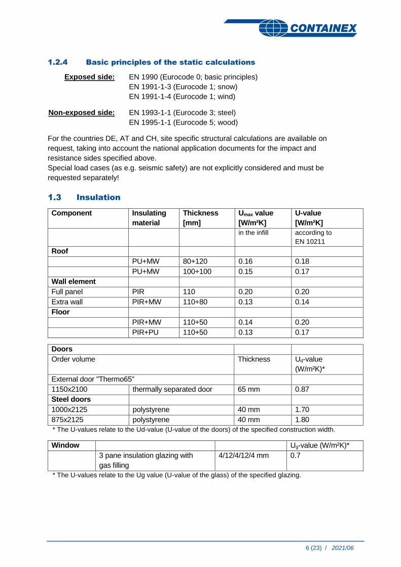
1.2.4 Basic principles of the static calculations
Exposed side:
EN 1990 (Eurocode 0; basic principles)
EN 1991-1-3 (Eurocode 1; snow)
EN 1991-1-4 (Eurocode 1; wind)
Non-exposed side:
EN 1993-1-1 (Eurocode 3; steel)
EN 1995-1-1 (Eurocode 5; wood)
For the countries DE, AT and CH, site specific structural calculations are available on
request, taking into account the national application documents for the impact and
resistance sides specified above.
Special load cases (as e.g. seismic safety) are not explicitly considered and must be
requested separately!
Insulation
Component Insulating
material
Thickness
[mm]
Umax value
[W/m²K]
U-value
[W/m²K]
in the infill according to
EN 10211
Roof
PU+MW 80+120 0.16 0.18
PU+MW 100+100 0.15 0.17
Wall element
Full panel PIR 110 0.20 0.20
Extra wall PIR+MW 110+80 0.13 0.14
Floor
PIR+MW 110+50 0.14 0.20
PIR+PU 110+50 0.13 0.17
Doors
Order volume Thickness Ud-value
(W/m²K)*
External door "Thermo65"
1150x2100 thermally separated door 65 mm 0.87
Steel doors
1000x2125 polystyrene 40 mm 1.70
875x2125 polystyrene 40 mm 1.80
* The U-values relate to the Ud-value (U-value of the doors) of the specified construction width.
Window Ug-value (W/m²K)*
3 pane insulation glazing with
gas filling
4/12/4/12/4 mm 0.7
* The U-values relate to the Ug value (U-value of the glass) of the specified glazing.

7 (23) / 2021/06
Container design
Frame construction
Floor frame:
Welded steel frame construction made of edged and rolled sections, 4 welded frame corners,
edged and welded cross beams, profile height of floor frame: 180 mm, no forklift pockets
available
Roof frame:
Welded steel frame construction made of edged and rolled sections, 4 welded frame corners,
edged and welded roof cross beams, profile height of roof frame: 250 mm
Corner column:
Made of edged and welded steel profiles, edge length 170 mm, screwed tightly to the floor and
roof frame
Rainwater drainage:
Insulated rainwater drainage pipes DN 75 inside the corner columns, unrestricted drainage of
the rainwater each on the front facing inwards at the lower frame corners
Floor structure
Insulation:
Insulating material:
110mm PIR + 50mm MW
PIR, fire performance B-s2, d0 according to EN 13501-1
Fire behaviour MW: fire behaviour A1 (not flammable) according
to EN 13501-1
110mm PIR + 50mm PU
PIR, fire performance B-s2, d0 according to EN 13501-1
Fire behaviour PU: D-s2, d0 according to EN 13501-1
Floor panel: Plywood panel - thickness21 mm
Е1 in accordance with EN 636:2012
Fire behaviour D-s2, d0 or Dfl-s1 according to EN 13501-1
8 (23) / 2021/06
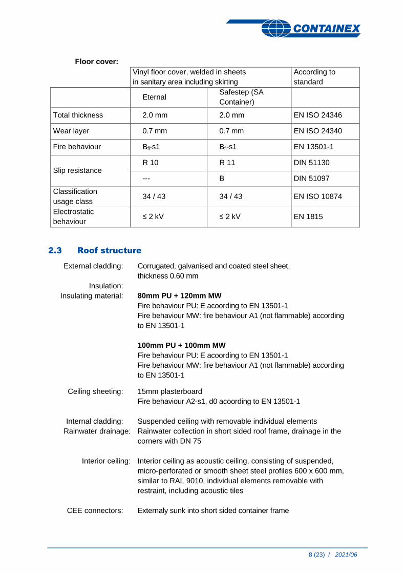
Floor cover:
Vinyl floor cover, welded in sheets
in sanitary area including skirting
According to
standard
Eternal Safestep (SA
Container)
Total thickness 2.0 mm 2.0 mm EN ISO 24346
Wear layer 0.7 mm 0.7 mm EN ISO 24340
Fire behaviour Bfl-s1 Bfl-s1 EN 13501-1
Slip resistance R 10 R 11 DIN 51130
--- B DIN 51097
Classification
usage class 34 / 43 34 / 43 EN ISO 10874
Electrostatic
behaviour ≤ 2 kV ≤ 2 kV EN 1815
Roof structure
External cladding: Corrugated, galvanised and coated steel sheet,
thickness 0.60 mm
Insulation:
Insulating material:
80mm PU + 120mm MW
Fire behaviour PU: E acoording to EN 13501-1
Fire behaviour MW: fire behaviour A1 (not flammable) according
to EN 13501-1
100mm PU + 100mm MW
Fire behaviour PU: E acoording to EN 13501-1
Fire behaviour MW: fire behaviour A1 (not flammable) according
to EN 13501-1
Ceiling sheeting: 15mm plasterboard
Fire behaviour A2-s1, d0 acoording to EN 13501-1
Internal cladding: Suspended ceiling with removable individual elements
Rainwater drainage: Rainwater collection in short sided roof frame, drainage in the
corners with DN 75
Interior ceiling: Interior ceiling as acoustic ceiling, consisting of suspended,
micro-perforated or smooth sheet steel profiles 600 x 600 mm,
similar to RAL 9010, individual elements removable with
restraint, including acoustic tiles
CEE connectors: Externaly sunk into short sided container frame

9 (23) / 2021/06
Wall panels
Panels: wall thickness 110 mm
Available items: - full panel *
- double panels / rest panels
* doors / windows only in full panel
External cladding: corrugated, galvanised and coated steel sheet, thickness 0,60 mm
Insulating
material:
PIR
Fire performance B-s2, d0 according to EN 13501-1
Insulation
thickness:
110 mm
Internal cladding:
galvanised steel sheet
Thickness 0.50 mm, colour: RAL 9010
Extra wall: wall thickness 90 mm
Available items: - on the short side and on the long side
Insulating
material:
MW
Fire behaviour MW: fire behaviour A1 (not flammable) according to
EN 13501-1
Insulation
thickness:
80 mm
Internal cladding:
galvanised steel sheet
9.5 mm plasterboard, fire behaviour A2-s1, d0 according to EN
13501-1
internal colour: RAL 9010
Doors
3.1.1 External door "Thermo65"
General: - right or left hand hinged
- outward opening
- including door closer
Door leaf: - all-over foam filling, thermally separated
- 4-sided double sealing levels
Frame: - thermally separated aluminium frame
- 3-sided sealing level
- including thermally separated aluminium-plastic threshold

10 (23) / 2021/06
Belts: - 3 two-part roller belts, 3-dimensionally adjustable, with protective caps,
pin-secured
Nominal dimension Clear opening
External
door:
1,150 x 2,100 mm 1,000 x 2,005 mm
Optional: - emergency exit according to EN 179
- panic bolt according to EN 1125
- 3-pane insulation glazing: W x H = 150 x ,1,603 mm
(external VSG clear / middle Float sandblasted / internal ESG clear)
3.1.2 Steel doors
Stop: - right or left hand hinged
Door leaf: - door leaf made of galvanised and laminated steel sheet on both sides
Frame: - steel frame with triangular wrap-around sealing
Belts: - 2 two-part door hinges
Dimensions: Nominal dimension Clear opening
Steel doors: 875 x 2,125 mm 811 x 2,065 mm
1,000 x 2,125 mm 936 x 2,065 mm
Optional: - emergency exit according to EN 179
- panic bolt according to EN 1125
- door closer
- insulated glazing:
border frame: plastic white
W x H = 238 x 1,108 mm ( ESG )
550 x 1,108 mm ( ESG )
550 x 450 mm ( ESG )
Windows
Specification: - frame with 3-pane insulated glazing (ESG) including gas filling and fitted
roller shutters
- externally with aluminium clips in cabin colour
- interiour colour: RAL 9010
- insulated roller shutter box with blind fastener
- aluminium slats, foamed, colour similar to RAL 9006
- one hand tilt & turn mechanism
ATTENTION: The built-in insulation glass is only suitable for use at altitudes up to 1,100 m
above sea level. Above 1,100 m sea level windows with a pressure compensating valve
need to be used.

11 (23) / 2021/06
Window options: Parapet height External dimension Clearance
Office window 1,030 mm 945 x 1,200 mm 820 x 1,080 mm
Sanitary window
(privacy glass)
1,525 mm 644 x 706 mm 520 x 580 mm
Double wing window
with floating mullion
(without centre bar)
1,030 mm 1,745 x 1,200 mm 1,560 x 1,015 mm
Optional: - VSG glazing
- venetian blinds (for office windows and double wing windows) with remote control
Glazing
Specification: Thermally separated aluminium frame with 3-pane insulated glazing
(ESG) including gas filling
- external paint: container colour
- interiour colour: RAL 9010
ATTENTION: The built-in insulation glass is only suitable for use at
altitudes up to 1,100 m above sea level. Above 1,100 m sea level
windows with a pressure compensating valve need to be used.
2070
1000LD 1000LD
2070 2070 2070 1600
Optional: - VSG glazing
- emergency exit according to EN 179
- panic bolt according to EN 1125
- venetian blinds with remote control

12 (23) / 2021/06
Partition walls
Available items: full panels on the front and long side, door elements (doors see point 3.1.2) on the front and long side
Total thickness: 80 mm or 120 mm
Insulating
material:
MW
fire behaviour MW: Fire behaviour A1 (not flammable) according to EN 13501-1
Insulation
thickness:
60 mm (for overall thickness 80 mm) or 100 mm (for overall thickness 120 mm)
internal cladding: double-sided plasterboard - sheet steel
9.5 mm plasterboard, fire behaviour A2-s1, d0 according to EN 13501-1
sheet steel decor: similar to RAL 9010

13 (23) / 2021/06
Fire resistance
Standard equipment: fire resistance class of the components in accordance with EN 13501-2
Supporting structure: R30
Roof construction REI30
Wall panels: EI30
Verification: Classification report according to EN13501-2, accredited institute IBS Linz
Electrical installations
Specification: concealed cabling
Protection class IP20
Plug insert according to country standards (VDE, ÖVE, NIN)
Country specific design / variations possible
Technical data
Basis VDE (= ÖVE, NIN) CH
Connection: recessed CEE external plug and socket connections
Voltage: 230 V / 3-poles / 32 A (3x6 mm²)
400 V / 5-poles / 32 A (5x6 mm²)
Frequency: 50 Hz
Protection: residual current operated device 40 A / 0.03 A, 2-poles (230 V) Type A X**
residual current operated device 40 A / 0,03 A, 4-poles (400 V) Type A X**
Distribution
box*: cavity distribution box, double row
Cable: type: H07ZZ-F & H07Z1-K (1x6mm²)
halogen-free mix, fire behaviour CCA– s1b, d1, a1
Electrical
circuits***:
light: circuit breaker 10 A , 2-poles , 3x1,5 mm² , Ik<10 kA
heating: circuit breaker 13 A , 2-poles , Ik<10 kA
3x 2,5mm²
socket circuit breaker 13 A ,
2-poles , Ik<10 kA
circuit breaker 10 A ,
2-poles , Ik<10 kA
3x2,5 mm²
Socket: twin wall sockets
single socket
* mounting on ceiling
** thermally protected with fuse at the same rated current
*** LC-release switch characteristic C
Optional: - spur
14 (23) / 2021/06
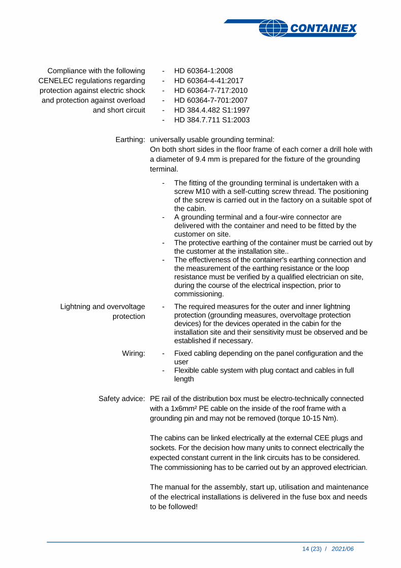
Compliance with the following
CENELEC regulations regarding
protection against electric shock
and protection against overload
and short circuit
- HD 60364-1:2008
- HD 60364-4-41:2017
- HD 60364-7-717:2010
- HD 60364-7-701:2007
- HD 384.4.482 S1:1997
- HD 384.7.711 S1:2003
Earthing: universally usable grounding terminal:
On both short sides in the floor frame of each corner a drill hole with
a diameter of 9.4 mm is prepared for the fixture of the grounding
terminal.
- The fitting of the grounding terminal is undertaken with a screw M10 with a self-cutting screw thread. The positioning of the screw is carried out in the factory on a suitable spot of the cabin.
- A grounding terminal and a four-wire connector are delivered with the container and need to be fitted by the customer on site.
- The protective earthing of the container must be carried out by the customer at the installation site..
- The effectiveness of the container's earthing connection and the measurement of the earthing resistance or the loop resistance must be verified by a qualified electrician on site, during the course of the electrical inspection, prior to commissioning.
Lightning and overvoltage
protection
- The required measures for the outer and inner lightning protection (grounding measures, overvoltage protection devices) for the devices operated in the cabin for the installation site and their sensitivity must be observed and be established if necessary.
Wiring: - Fixed cabling depending on the panel configuration and the user
- Flexible cable system with plug contact and cables in full length
Safety advice: PE rail of the distribution box must be electro-technically connected
with a 1x6mm² PE cable on the inside of the roof frame with a
grounding pin and may not be removed (torque 10-15 Nm).
The cabins can be linked electrically at the external CEE plugs and
sockets. For the decision how many units to connect electrically the
expected constant current in the link circuits has to be considered.
The commissioning has to be carried out by an approved electrician.
The manual for the assembly, start up, utilisation and maintenance
of the electrical installations is delivered in the fuse box and needs
to be followed!

15 (23) / 2021/06
Before connecting the cabin to the supplying low voltage grid all
appliances (consumer loads) need to be switched off and earthing
needs to be ensured (earthing feed cable and earthing connecting
lines between the cabins need to checked on potential equity and
low Ohm level).
Attention: The supply- and connection cables are made for an
operating voltage of max. 32 Ampere. These aren't secured with a
overcurrent protection device. The connection of the cabins to the
external electrical power supply may be only undertaken by a
certified specialist company.
Before using the cabin (modular building) for the first time the
efectiveness of the protection measures for the fault protection
need to be checked by an authorised specialist company.
Attention: The commissioning of boilers and/or under table units is
only permitted if they are filled!
Cleaning with a high-pressure cleaner is FORBIDDEN..
The electrical equipment of the cabin may not be cleaned by a
direct water jet under any circumstances.
If the containers are delivered into areas with increased lightning activity further measurements have to be taken under account to prevent overvoltage depending on the country specific rules.
When cabins are placed near the ocean it is necessary to consider the special atmospheric conditions (salt content and humidity of the air) when the intervals for the periodic inspections by the operator are defined.
In case machines or appliances with high starting current peaks are used (according to the manual of the respective appliances) adequate RCD/MCB must be used.
The electrical fittings in the cabin are designed for minimal vibration exposure. If the exposure is higher, appropriate measures (and plug/screw contact checks) must be taken depending on the national technical regulations.
If the cabins are used in areas with earthquake risks, the national regulations must be applied and the equipment must be adapted accordingly.
The choice of the external linking cables of the cabins has to suit the country's national technical regulations.
The cabins have to be secured against thermal overload with a type gL fuse or gG with max. IN = 32A.

16 (23) / 2021/06
Heating and air conditioning
Individual heating through frost monitors, electric convectors or fan heaters with thermostat
control and safety switch for overheating. Mechanical ventilation options available with
electrical ventilators.
Regular ventilation of the rooms must be provided. A relative humidity of 60 % should not
be exceeded in order to avoid condensation.
Output:
Description: hygrostatic controlled
ventilator 170 m³/h
(depending on number of cabins) convector heater 1 2 kW
convector heater 0.5 kW
fan heater 2 kW
All safety distances and instructions issued by the supplier for the equipment must be adhered
to!
The appropriate manuals and instructions are sent with the cabins.
Design options
General equipment
- cable bushing in the panel - telephone duct in the panel
- cable bushing in the panel fastening - motion and presence detector
- cable channel on panel - ventilation unit VL-100
Sanitary fixtures
- sanitary fixtures accessible to disabled persons
- sanitary connection sunk into the panel
- Shower - intermediate panel
- boiler: 50 l / 80 l / 150 l - soap dispenser
- pressure reduction valve - Stop & Go fitting for wash hand basin
- wet room electrics (optional) - continuous-flow water heater (for pressureless fittings)
- ceramic hand wash basin - urinal
- electrical hand dryer - water installations (water inlet and outlet)
- mirror - WC cabin
- paper towel dispenser

17 (23) / 2021/06
Water installations
Supply: supply using ½“, ¾“ or 1“ pipe, sideways through cabin wall concealed cabling
Internal: PP-R pipework (according to EN ISO 15874)
Operating pressure: max. permitted operating / connection pressure 4 bar
Warm water preparation:
by using electric boilers, depending on the cabin type (50, 80 or 150 liters)
ATTENTION: The boilers with 50/80/150 litres capacity are suitable for a max.
operating pressure of 6 bar. A higher water pressure is reduced
with an appropriate pressure reducing valve!
Discharge: The waste water is collected via PVC pipes, DN 50 or DN 110 (external diameter 50 or 110mm) and discharged sideways through the cabin wall. The customer must drain any sewage into an approved sewage network in accordance with local regulations for water and faecal drains.
NOTE: Should the cabin not be used at temperatures below +3°C, the entire piping system must be emptied including the boiler (risk of frost!). If residual water is left over (eg. drainage water, etc.) an anti-freeze agent must be used to prevent damage from water freezing. The shut-off valve on the water conduit must always stay open.
Paint
Paint system with high weather and aging durability, suitable for city
and industry atmosphere.
Wall panels: 25 µm coating thickness
Frame: 75-120 µm coating thickness
The painting of above mentioned parts is carried out with different
types of production.. These achieve shades similar to RAL. We do not
accept liability for colour variations in comparison with the RAL tones..
Certifications
CE marking in accordance with EN 1090 EXC 2

18 (23) / 2021/06
Miscellaneous
Layout possibilities
ground floor
valid for 10ʹ – 16ʹ – 20ʹ – 24ʹ - TP20 – 3P20 – 4P20
No restriction on the open room sizes!
Attention: BP/SP 24' ground floor
version without additional central
support - it is not possible to add
storeys at a later date!
Note: 3P20 and 4P20 are designed
without additional central supports
2- storey
valid for 10ʹ – 16ʹ – 20ʹ - TP20 - 3P20 - 4P20
No restriction on the open room sizes!
Minimum requirement 2x1x2 (reduced
wind loads: 22.5 m/s)
The block 2x1x2 can be expanded as
required
Note: 3P20 and 4P20 are designed
without additional central supports
3- storey
valid for 10ʹ – 16ʹ – 20ʹ - TP20 - 3P20 - 4P20
No restriction on the open room sizes!
Minimum requirement single row 3x1x3
(reduced wind loads: 22.5 m/s)
Minimum requirement double row
3x2x3 (reduced wind loads: 22.5 m/s)
These blocks can be expanded as
required
Note: 3P20 and 4P20 are designed
without additional central supports

19 (23) / 2021/06
Transport
Containers must be transported on suitable trucks. The local laws for load securing must be
adhered to.
The containers are not suitable for rail transport. The containers must be transported empty.
Open container sides must be closed with appropriate covers before transport.
Handling
The following handling regulations for the cabins must be observed:
The 10', 16', 20' and 20'x10' containers can be lifted by crane. The ropes/chains need to be fastened to the upper cabin corners. The angle between the rope/chain and the horizontal line must be a minimum of 60° (picture 1). The necessary rope length for a 20' container is at least 6.055 m.
The 24' containers can also be lifted by crane. The ropes must be attached to the eyebolts/crane eyes screwed on at the top (not the cabin corners!). The angle between the lifting rope and the horizontal line must be a minimum of 60°.
Due to the construction and design, handling with a spreader is not possible!
The cabins may not be handled when loaded.
min. required rope length:
10‘: 2,989 mm
16‘: 4,880 mm
20‘:6,055 mm

20 (23) / 2021/06
Installation / Assembly / Statics / Maintenance
General:
Each individual cabin must be placed on foundations provided on site with the respective number
of support points (see item 11 support points). The dimensions of the foundation has to be
adapted to local circumstances, norms and frost line, under consideration of the local soil
condition and the maximum possible loads. The levelness of the foundation is a precondition for
a smooth assembly and the failure-free standing of the entire construction. Should the load points
not be horizontally aligned, these must be highlighted in the width of the profile.
The design of the foundations must ensure a free flow of rain water.
During set up or placement of the cabin (constructions), maximum permitted loads and regional
conditions (e.g. snow loads) must be taken into account. Packaging and transport covers must
be disposed of or stored by the customer.
Possible combinations of several cabins:
Individual cabins can be placed side by side, one behind the other or one on top of the other,
taking into account the configuration options (see item 10.1) and the max. payloads.
The cabins must be stacked exactly on top of each other. The special CTX stacking cones must
be used. The container roof is not suitable for storage of goods and materials.
The CONTAINEX assembly instructions and the service notes must be adhered to and can be
sent upon request.
Handling and installation instructions are enclosed in the cabin and must be observed.
Before starting the work, a risk analysis must be carried out in accordance with the local
requirements and the applicable provisions on site. Necessary measures must be implemented
by the assembly personnel. Particularly when working on the cabin roof, safeguards must be put
in place to stop anyone from falling.
Sanitary fittings:
After connecting to the water supply the entire water circulation should be checked once more for
water tightness (possible loosening during transport).
Containex denies any warranty for damages, which may result from placement contrary to the
principles. Liability for consequential damages is excluded on principle.
Regulatory and legal requirements regarding storage, installation and use of cabins must be
observed by the customer.
he suitability of the cabin (modularsystem) and any supplied accessories (e.g. stairs, air
conditioning etc.) for the planned application must be checked by the customer.
Subject to technical alterations!

21 (23) / 2021/06
Support points
Each individual cabin must be placed on foundations provided on site with the respective
number of support points. The smallest foundation size is 20 x 20 cm, but dimensions of the
foundation have to be adapted to local circumstances, norms and frost line, under consideration
of the local soil condition and the maximum possible loads. The customer must carry out the
relevant measures.
Support points BP / SP 10', 16' and 20'
…minimum required container contact points
Support points BP / SP 24'
…minimum required container contact points

22 (23) / 2021/06
Support points corridor cabin GP 16' and 24'
…minimum required container contact points
Support points 3P20 and 4P20
…minimum required container contact points

23 (23) / 2021/06
Support points internal staircase cabin TP20
…minimum required container contact points
…support points depending on the type of stairs
or strip foundation version
…minimum required container contact points Note: Foundation loads are disclosed on a project-specific basis. Additional support points may be required depending on the installation variant. Further technical information upon request - subject to technical alterations.