control - auburn university samuel ginn college of …troppel/courses/1110 2012c intro… · ·...
TRANSCRIPT
6 • 1
Control
Inventor’s Guide
05/0
8
ControlTable Of Contents:
Introduction to the Control Subsystem 6.2
Concepts to Understand 6.15
Subsystem Interactions 6.20

6 • 2
Control
Inventor’s Guide
05/0
8
Transmitter
RF receiver module
The Control Subsystem provides the link between the robot and the human operator. Commands are entered through the joysticks and buttons on the RF Transmitter, and sent through the air via FM radio waves to the RF Receiver module mounted on the robot.
In addition to providing the control link, the transmitter can be used to alter robot control options, such as drive configuration and joystick trims and scaling.
Introduction to the Control Subsystem
There are also a number of advanced Transmitter options as well. These options provide functions most users will not need. For more information on these advanced configuration settings, refer to Appendices D and E.
6 • 3
Control
Inventor’s Guide
05/0
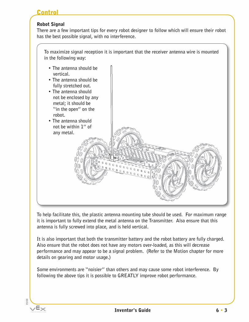
8Robot SignalThere are a few important tips for every robot designer to follow which will ensure their robot has the best possible signal, with no interference.
To help facilitate this, the plastic antenna mounting tube should be used. For maximum range it is important to fully extend the metal antenna on the Transmitter. Also ensure that this antenna is fully screwed into place, and is held vertical.
It is also important that both the transmitter battery and the robot battery are fully charged. Also ensure that the robot does not have any motors over-loaded, as this will decrease performance and may appear to be a signal problem. (Refer to the Motion chapter for more details on gearing and motor usage.)
Some environments are “noisier” than others and may cause some robot interference. By following the above tips it is possible to GREATLY improve robot performance.
To maximize signal reception it is important that the receiver antenna wire is mounted in the following way:
• The antenna should be vertical.
• The antenna should be fully stretched out.
• The antenna should not be enclosed by any metal; it should be “in the open” on the robot.
• The antenna should not be within 1” of any metal.

6 • 4
Control
Inventor’s Guide
05/0
8
Basic Transmitter OperationThe Transmitter joysticks can be configured to work in two basic configurations. To check or switch between configurations, follow these instructions:
1. Turn on the Transmitter by sliding the power switch up to the ON position.
2. Enter the menu on the transmitter by holding down both the Mode and Select buttons at the same time next to the LCD until the menu is displayed on the LCD screen.
3. Enter the Driving Mode Adjustment menu by pressing the Mode button until DRIVE is displayed on the left side of the LCD screen (it’s the last menu). You will pass over the following advanced menus: CONFIG, REVERSE, SCALE, EDITPT., TRIM, and PMIX.
For more information on these advanced menus, refer to Appendix E.
4. The current driving mode is displayed. This will be either “23” or “12”. Push up or down toward either the + or – on the data input button on the right side of the LCD to switch between these two modes. The two modes are explained on the following pages.
Control Subsystem

6 • 5
Control
Inventor’s Guide
05/0
8Control Subsystem, continued
This control configuration uses the vertical axes of both sticks to control the two drive motors independently. The name “23 mode” comes from the fact that the vertical axis of the right stick is “Control Channel 2”, and the vertical axis of the left stick is “Control Channel 3”, hence axes 2 and 3 (“23”) are being used to drive.
In this configuration, the left stick controls the motor attached to Motor Port 3, and the right stick controls the motor attached to Motor Port 2.
WARNING:When powering on a robot, ensure that it is positioned in such a way that it will not damage itself or its surroundings upon startup. It is possible that the receiver could accidentally pick up other radio waves which will cause the robot to behave erratically and unexpectedly. Use Caution!
Forward
Left stick Right stick
Reverse
Turn Left
Turn Right
Tank-style control (“23” mode – default)
Note: Make sure there are no jumper clips on Analog/Digital Ports 13, 14, 15, or 16 on the Microcontroller, otherwise your robot will behave differently from what is listed here. For details on how to use these jumpers to configure advanced control features, visit the Logic Subsystem chapter.

6 • 6
Control
Inventor’s Guide
05/0
8
This control configuration uses only the right joystick to control both forward/reverse motion and turning motion. The name “12 mode” comes from the fact that the hori-zontal axis of the right stick is “Control Channel 1”, and the vertical axis is “Control Channel 2”, hence axes 1 and 2 (“12”) are being used to drive.
In this configuration, the right stick controls both throttle, direction and turning.
Forward
Reverse
Turn Left
Turn Right
Left stick Right stick
Arcade-style control (“12” mode)
Note: Make sure there are no jumper clips on Analog/Digital Ports 13, 14, 15, or 16 on the Microcontroller, otherwise your robot will behave differently from what is listed here. For details on how to use these jumpers to configure advanced control features, visit the Logic Subsystem chapter.
Control Subsystem, continued
6 • 7
Control
Inventor’s Guide
05/0
8Control Subsystem, continued
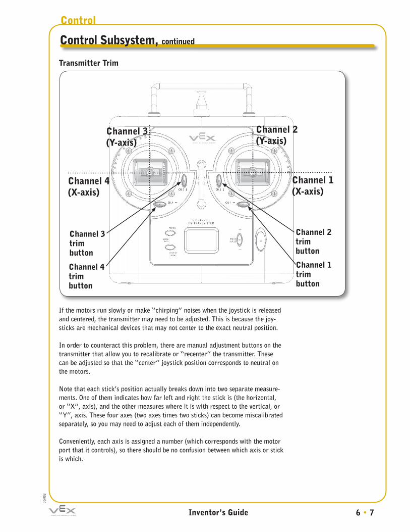
Transmitter Trim
If the motors run slowly or make “chirping” noises when the joystick is released and centered, the transmitter may need to be adjusted. This is because the joy-sticks are mechanical devices that may not center to the exact neutral position.
In order to counteract this problem, there are manual adjustment buttons on the transmitter that allow you to recalibrate or “recenter” the transmitter. These can be adjusted so that the “center” joystick position corresponds to neutral on the motors.
Note that each stick’s position actually breaks down into two separate measure-ments. One of them indicates how far left and right the stick is (the horizontal, or “X”, axis), and the other measures where it is with respect to the vertical, or “Y”, axis. These four axes (two axes times two sticks) can become miscalibrated separately, so you may need to adjust each of them independently.
Conveniently, each axis is assigned a number (which corresponds with the motor port that it controls), so there should be no confusion between which axis or stick is which.
Channel 4 (X-axis)
Channel 1 (X-axis)
Channel 3 (Y-axis)
Channel 2 (Y-axis)
Channel 2trimbutton
Channel 1trimbutton
Channel 3trimbutton
Channel 4trimbutton
6 • 8
Control
Inventor’s Guide
05/0
8
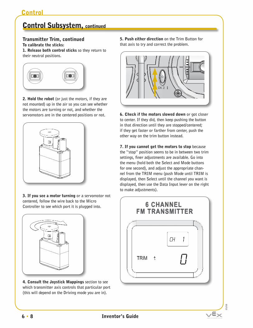
Transmitter Trim, continuedTo calibrate the sticks:1. Release both control sticks so they return to their neutral positions.
2. Hold the robot (or just the motors, if they are not mounted) up in the air so you can see whether the motors are turning or not, and whether the servomotors are in the centered positions or not.
3. If you see a motor turning or a servomotor not centered, follow the wire back to the Micro Controller to see which port it is plugged into.
4. Consult the Joystick Mappings section to see which transmitter axis controls that particular port (this will depend on the Driving mode you are in).
5. Push either direction on the Trim Button for that axis to try and correct the problem.
6. Check if the motors slowed down or got closer to center. If they did, then keep pushing the button in that direction until they are stopped/centered; if they get faster or farther from center, push the other way on the trim button instead.
7. If you cannot get the motors to stop because the “stop” position seems to be in between two trim settings, finer adjustments are available. Go into the menu (hold both the Select and Mode buttons for one second), and adjust the appropriate chan-nel from the TRIM menu (push Mode until TRIM is displayed, then Select until the channel you want is displayed, then use the Data Input lever on the right to make adjustments).
Control Subsystem, continued
6 • 9
Control
Inventor’s Guide
05/0
8
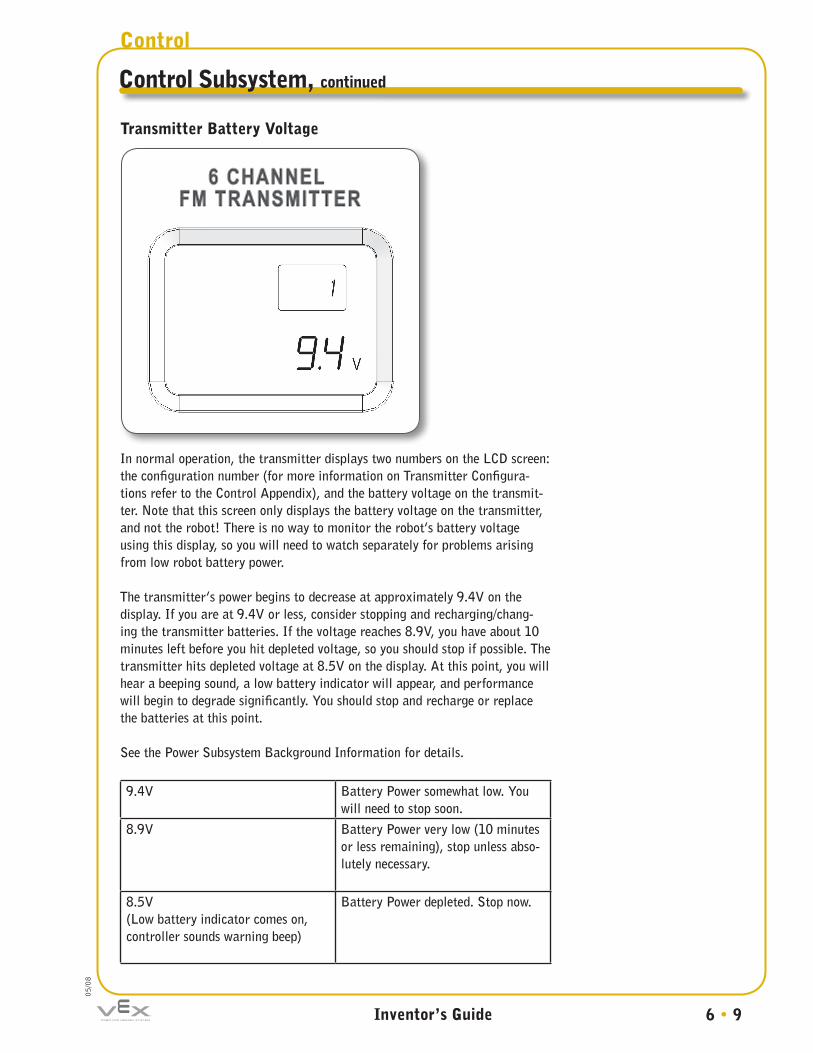
Transmitter Battery Voltage
In normal operation, the transmitter displays two numbers on the LCD screen: the configuration number (for more information on Transmitter Configura-tions refer to the Control Appendix), and the battery voltage on the transmit-ter. Note that this screen only displays the battery voltage on the transmitter, and not the robot! There is no way to monitor the robot’s battery voltage using this display, so you will need to watch separately for problems arising from low robot battery power.
The transmitter’s power begins to decrease at approximately 9.4V on the display. If you are at 9.4V or less, consider stopping and recharging/chang-ing the transmitter batteries. If the voltage reaches 8.9V, you have about 10 minutes left before you hit depleted voltage, so you should stop if possible. The transmitter hits depleted voltage at 8.5V on the display. At this point, you will hear a beeping sound, a low battery indicator will appear, and performance will begin to degrade significantly. You should stop and recharge or replace the batteries at this point.
See the Power Subsystem Background Information for details.
9.4V Battery Power somewhat low. You will need to stop soon.
8.9V Battery Power very low (10 minutes or less remaining), stop unless abso-lutely necessary.
8.5V(Low battery indicator comes on, controller sounds warning beep)
Battery Power depleted. Stop now.
Control Subsystem, continued

6 • 10
Control
Inventor’s Guide
05/0
8
Stick Mode Stick Mode configuration is accessed differently from the other menus. To access this mode, you must hold down Mode and Select while turning the transmitter on, rather than pressing them once it is already on.
The only option you can change in the Stick Mode, is between “2” and “1”. 2 is the default, and you should leave it this way unless you have a specific reason for changing it. Setting the Stick Mode to 1 will swap axes 2 and 3, so the vertical axis of the left stick becomes channel 2, and the vertical axis of the right stick becomes channel 3. Unless you have a good reason to change this, you should leave the Stick Mode on 2.
Tether PortSometimes for diagnostic purposes, it may be useful to plug the transmitter directly into the Microcontroller, and bypass the need for the RF Receiver. This would help you determine, for instance, whether radio interference is at fault for your robot behaving strangely, or if some other factor is to blame.
In order to use the tether feature, you will need to purchase a cable. Any tele-phone handset extension cable will work (the coiled cable that goes from the handset to the base of a corded phone, not the cable that goes from the phone to the wall).
Control Subsystem, continued

6 • 11
Control
Inventor’s Guide
05/0
8
Tether Port, continued To use the tether feature:1. Hook up one end of the cable to the back of your Radio Transmitter, in the port marked “Tether Port”. You will need to lift up the rubber cover to gain access to the port.
2. Plug the other end directly into the Rx1 port of your Microcontroller.
(Note: The RX2 port allows two drivers to control a single robot. More information on this is given in the appendices.)
3. Turn the Transmitter on by pushing the power switch on the Transmitter to the ON position. The Transmitter must have properly working batteries.
4. Turn the Microcontroller on by flipping the power switch on the Microcontroller to the ON position. The Microcontroller must have properly working batteries.
5. Test your robot. The controls should operate exactly as they would remotely over radio, but without the possibility of radio interference or other similar issues.
Control Subsystem, continued
6 • 12
Control
Inventor’s Guide
05/0
8
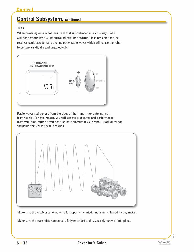
Tips When powering on a robot, ensure that it is positioned in such a way that it will not damage itself or its surroundings upon startup. It is possible that the receiver could accidentally pick up other radio waves which will cause the robot to behave erratically and unexpectedly.
Radio waves radiate out from the sides of the transmitter antenna, not from the tip. For this reason, you will get the best range and performance from your transmitter if you don’t point it directly at your robot. Both antennas should be vertical for best reception.
Control Subsystem, continued
Make sure the receiver antenna wire is properly mounted, and is not shielded by any metal.
Make sure the transmitter antenna is fully extended and is securely screwed into place.

6 • 13
Control
Inventor’s Guide
05/0
8
Tips, continued If you accidentally change a setting on your transmitter that you did not intend to change, you can reset the controls to the factory default setting through the CONFIG menu.
1. Turn the transmitter on by pushing the power switch into the ON position.
2. Hold down the Mode and Select buttons for two seconds until the menu appears. CONFIG should be selected by default.
3. If you wish to reset the data for a different robot configuration, press the “+” button on the Data Input button until the configuration number you want is displayed. If you are not using multiple configurations (see the Transmitter Appendix), then ignore this step.
4. Press the Select button. The letters CL (for “clear”) should appear.
5. Push up or down toward the “+” or “–” on the Data Input button and hold for 2 seconds to reset the controls to default settings for the selected config number. The Transmitter will beep when the configuration is reset.
Control Subsystem, continued

6 • 14
Control
Inventor’s Guide
05/0
8
Tips, continued
Remember that the transmitter does not monitor robot battery voltage, only its own transmitter battery. Watch the robot to see if it seems to be low on power.
If more than one robot is operating in the same area, be sure that the ro-bots are operating on different frequencies or that one of the robots is operat-ing via a tether, otherwise their commands will interfere with each other (see Frequency Crystals in Background Information in this chapter).
If you own more than one set of frequency crystals, be sure that the frequency module in your transmitter matches the crystal in your RF receiver module (see Frequency Crystals in this chapter).
Control Subsystem, continued
The FCC Wants You to KnowThis equipment has been tested and found to comply with the limits for radio controlled devices, pursuant to Part 15 and Part 95 of the FCC Rules. These limits are designed to provide reasonable protection against harmful interference. This equipment generates, uses, and can radiate radio frequency energy and, if not installed and used in accordance with the instructions, may cause harmful interference to radio communications. However, there is no guarantee that interference will not occur in a particular installation. If this equipment does cause harmful interference to radio or television reception, which can be determined by turning the equipment off and on, the user is encouraged to try to correct the interference by one or more of the following measures: •Reorientorrelocatethereceivingantenna. •Increasetheseparationbetweentheequipmentandreceiver. •Consultyourlocalelectronicsstoreoranexperiencedradio/TVtechnicianforhelp. •Ifyoucannoteliminatetheinterference,theFCCrequiresthatyoustopusing your R/C transmitter.Warning:ChangesormodificationsnotexpresslyapprovedbyInnovationFirstmaycauseinterferenceandvoidtheuser’sauthoritytooperatetheequipment.OnlyuseauthorizedcrystalsdesignedforusewiththeVEXRobotics Design System RF Receiver and Transmitter.

6 • 15
Control
Inventor’s Guide
05/0
8
When electrons accelerate, they radiate an electromagnetic signal that moves at the speed of light. By accelerating and decelerating electrons in a controlled pattern, a wave pattern can be generated in the radiated electromagnetic field. These are called electromagnetic waves. Electromagnetic waves move at the speed of light, and are therefore very good at carrying information quickly from one place to another.
Electromagnetic Waves
eee
eeee
Concepts to Understand
Electromagnetic Waves

6 • 16
Control
Inventor’s Guide
05/0
8
The VEX Radio Transmitter uses an electromagnetic wave with a certain frequency to transmit data to the RF receiver module. Frequency modulation (FM) is a way of encoding information in wave patterns such as these.
Waves have several basic properties, including amplitude and frequency. In frequency modulation, the frequency of the basic wave, known as a carrier wave, is modified by combining it with another signal known as the modulating wave. This produces a final wave that looks irregular, but is really carrying the data from the signal wave on top of the carrier wave.
FM is less susceptible to interference than other radio transmission methods, such as amplitude modulation (AM) or direct transmission of the signal wave.
carriersignal
output
Concepts to Understand, continued
Frequency-Modulated Signals

6 • 17
Control
Inventor’s Guide
05/0
8
Since every FM signal has a set carrier wave frequency, different carrier waves can be used to carry different signals at the same time without causing interference. The air around you is filled with a multitude of different FM wave frequencies being sent from many sources, and they don’t interfere with each other, because their carrier waves all have different frequencies.
To prevent chaos, there are a limited number of frequencies that can be used for radio control. In the US, the Federal Communications Commission (FCC) is responsible for distributing these frequencies among the various industries that want to use RC. Ground vehicles operating by FM radio control have been assigned the 75MHz band and must transmit their control information using a carrier frequency that is between 75MHz and 76Mhz.
Exact frequencies (which have names like 75.410MHz) are often hard to remember, or inconvenient to talk about. The frequencies that are used to transmit data in the 75MHz band are therefore also assigned channel numbers. A channel is like a nickname for a certain frequency. The carrier frequency 75.410MHz, for instance, can also be called Channel 61 for convenience.
Be careful with the term channel, however, because the term is also used to refer to “control channels,” which are used to number the inputs on the transmitter (each joystick has two control channels, for instance: one for the x-axis and one for the y-axis). You will need to infer from usage context whether “channel” is being used to refer to a “radio frequency channel” (frequency) or a “control channel” (axis).
Concepts to Understand, continued
Radio Frequencies
Radio Channels

6 • 18
Control
Inventor’s Guide
05/0
8
When more than one Transmitter is running in the same area (e.g. during a competition), there is potential for trouble. How can the robot determine which transmitter is sending which signal?
If all VEX Radio Transmitters and RF Receivers were to operate on the same frequency, then there would be no way for the robot to discriminate between signals. However, the VEX Radio Transmitter and Receivers are designed to be able to use a number of different FM carrier frequencies (see Radio Frequencies above). As long as each transmitter-receiver pair uses a different frequency, the robots won’t get confused.
The Radio Transmitter and RF Receiver have set frequencies according to a special radio frequency crystal that is installed in them. A transmitter frequency crystal and RF receiver crystal set comes pre-installed in both the Transmitter and Receiver, but they are modular, and can be removed and replaced only with a VEX approved transmitter frequency crystal and matching RF receiver crystal. In order to compete in an environment with multiple robots or to use multiple transmitters, you will need to ensure that all transmitter frequency crystals and RF receiver crystal pairs are unique.
Concepts to Understand, continued
receiver crystal transmitter frequency module
Frequency Crystals
CH.61
CH.61

6 • 19
Control
Inventor’s Guide
05/0
8
Remember, crystals come in pairs! The transmitter frequency crystal determines what frequency the transmitter will use to send commands, and the RF receiver crystal tells it what frequency to listen on. If the crystals in the transmitter and the receiver don’t match, they will not be able to communicate. Always use crystals of the same frequency on both the transmitter and receiver for a given robot.
TX/RX = Ch. 61 (75.410MHz )TX/RX = Ch. 89 (75.970MHz )Additional Crystal Kit #1 = Ch. 65, 69, 81, 85 (75.490,
75.570, 75.810, 75.890MHz)Additional Crystal Kit #2 = Ch. 63, 67, 83, 87 (75.450,
75.530, 75.850, 75.930MHz)
Crystals available for use with the VEX Robotics Design System
The joysticks on the radio control transmitter are actually part of a variable resistor component in the transmitter circuit. Pushing the sticks in one direction or another changes the electrical resistance of a potentiometer inside the transmitter, which in turn causes a change in voltage. The transmitter will then send a different signal to the receiver based on this voltage. For instance, the transmitter may expect the sticks to provide a resistance that produces a voltage of 2.5V when centered.
Miscalibration occurs when the joystick circuit does not generate the expected voltage for a given position of the sticks. For any number of reasons, from manufacturing tolerances to battery voltage drop, the sticks may start providing a different number while centered, say 3.7V.
The transmitter will have no idea what is causing the 3.7V, so it will assume that it is because the stick is in the position that would normally produce a 3.7V reading. It will send a signal to the receiver indicating that the stick is in the 3.7V position. Clearly, this is not correct, and this miscommunication will cause the robot to behave oddly, because it will be responding to commands that aren’t actually being given on the stick. “Trim Setting Adjustment” instructions (pages 6-8) will correct this condition.
Concepts to Understand, continued
Frequency Crystals, continued
Joystick Mechanism
Inventors should only use VEX authorized RF receiver crystals and transmitter frequency crystals.

6 • 20
Control
Inventor’s Guide
05/0
8
Subsystem Interactions
How does the Control Subsystem interact with…
…the Structure Subsystem?
…the Motion Subsystem?
…the Sensor Subsystem?
…the Power Subsystem?
… the Logic Subsystem?
• Unlike radio-controlled cars, the VEX robot does not directly tie the Control Subsystem into the Motion Subsystem. The commands generated by the operator using the Transmitter are sent to the radio receiver on the robot, but from there, the commands are given to the Microcontroller, which takes this and other information into account when deciding which command to give to the Motion components.
• The Control and Sensor Subsystems complement each other to achieve better control of the robot. The Control Subsystem provides human control over the robot, but the human operator does not always have perfect control, or the perfect point of view to see the robot’s position. The Sensor Subsystem gives the robot the ability to make its own informed decisions, and can be a substantial aid to the human operator.
• The Sensor Subsystem and the Control Subsystem both provide inputs which are processed identically in the VEX Microcontroller.
• The Microcontroller module controls the flow of commands from the human operator to the robot. The Microcontroller ultimately decides whether to pass joystick commands on to the motors, to modify them, or to override them, based on its programmed behavior and other information available to it (from sensors, for instance).
• The RF Receiver module is connected to the VEX Microcontroller through the 9” RJ-10 cable that runs from the back of the Receiver into the back of the Microcontroller. Up to two receivers can be supported simultaneously.
• If desired, the Transmitter can be hooked directly into the VEX Microcontroller using a tether cable, bypassing the RF Receiver.
• The specific way that the robot will respond to joystick movement is determined by a combination of Radio Transmitter and Microcontroller settings. See the Control Appendix for a full listing of control layouts.
• Broadcasting radio waves takes a significant amount of electrical power. The 8 AA batteries (or 9.6V battery pack) installed in the VEX Transmitter provide the Transmitter with all the power it needs to operate its internal circuitry and send out radio waves carrying commands to the receiver.
• The RF Receiver mounted onboard the robot, on the other hand, draws its power from the Power Subsystem indirectly, through the Microcontroller (which is part of the Logic Subsystem).
• The Structure Subsystem will generally provide a place to store/protect the RF Receiver module on the robot.
• The Structure Subsystem can shield radio signals and interfere with the Control Subsystem. It is important to correctly mount the antenna to minimize this interference.