control device with direct drive and indirect … · instrucciones at-m-kl ... conmutadores...
TRANSCRIPT

Commutatori lineari fuori tensione per trasformatori in olio
Edi/Rev 01/16
S.r.l.
CONTROL DEVICE WITH DIRECT DRIVE AND INDIRECT TRANSMISSION
WARNING: Do not operate while the transformer is energized
INSTRUCCIONES AT-M-KL COM MANDO DIRECTO Y MANDO DE TRANSMISION
ADVERTENCIAS: Hay que manobriar fuera de tension
Conmutadores lineares, para instalarse en aceite y maniobras fuera de tension

2
ESPA
ÑOL
ENGL
ISH
INDEX
1. cover
2. summary
3. general warnings
3. general
4. for end user
5. for transformer manufacturer
6. storage
6. drying process
ÍNDICE
1. portada
2. índice
7. advertencias
8. informaciones generales
8. para el usuario final
9. para el constructor del transformador
10. conservación
10. procedimiento del secado

3
ENGL
ISH
MAIN CHARATERISTIC this is an off-circuit tap changers. It means all switching manoeuvre must be performed after disconnecting transformer by the electrical net opening the sectionalising switches, both HV and LV side, so transformer becomes off-circuit.
DIMENSION All dimension reported in case of drawings attached are in millimetres (mm)
TRANSFORMER OILAll our tap changers are suitable to work in oil immersed transformers according to standard IEC 60296. In case user need to use specific oil (silicon, synthetic or vegetal) it is necessary consulted CAPT technical office who verify the functionality of tap in all the mechanicals, electrical and chemical characteristics.
INSULATION MATERIALThe insulating materials used are bakelite (paper laminates and phenoplastic resin) of “E” thermal class.
GASKETGasket supply in our tap changers and in our transmission drive handles are type NBR and they are suitable for oil transformer, indicate for temperature in oil between -25°C and +100°C and for temperature on air between -25°C and +40°C, according to IEC 60214-1/2. On request, we can supply tap changer with special rubber for low temperature till -60°C and for high temperature till +200°. These gaskets are suitable for oil transformer and they can be in HNBR, VITON, in Silicon rubber. They can be used in arctic or tropical conditions.
DRYING TREATMENTDifferent drying treatment can be process by customer: oven, in a vacuum autoclave, vapour-phase or other. In this process is normally included tap changer too. The maximum temperature suggested by CAPT for our tap changers is 100°C-120°C for a time or 24÷36h.
DRYING TREATMENT IN CASE OF BEVEL GEAR AND DRIVE HANDLEIt is better to leave out from drying treatment the drive handle and bevel gear.In case it is impossible to leave them out, we suggest to strictly respect the temperature recommended when you need drive handle with micro switch for electrical lock or electrical position transmitter.
WHEN CONTACT CAPTIn the following cases please contact CAPT:• For temperature condition higher/lower then suggest• For temperature condition higher/lower then suggest• For hard temperature conditions, with possibility of snow or sand storming, or in potential seismic area.
GENERAL WARNINGS

4
ENGL
ISH
INTERNATIONAL STANDARD: IEC60214-1 e IEC60214-2For all matters not specifically declared remains valid the updated international standard IEC60214-1 & IEC60214-2.
OVERLOADSCAPT Tap Changers do not restrict the transformer emergency loading according to IEC 60076-7.
To perform the switching operation, the operator must proceed as follows. The first one and indispensable operation is to disconnect transformer by the electrical net opening the sectionalising switches, both HV and LV side, so transformer becomes off-circuit. After that is necessary to open the padlock (where applied), lift the blocking knob on the drive and turn the drive clockwise or anticlockwise according to the position change required up to reach the new position. Then put inside the blocking knob so that the final part comes in the correspondent hole, at the end replace if necessary the padlock.N. B. ALL SWITCHING MANOEUVRE MUST BE PERFORMED OFF-CIRCUIT.
SERIES TYPE kV A N° positions
ATdirect drive
AT/ ATC/ ATS24-36-52-72,5 120÷600
2÷9
ATSP / ATST / ATCT 2
MMT/ MC/ MS
24-36-52-72,5 120÷6002÷15
MSP / MST / MTCT 2
KKL/ KLD 24-36-52-72,5
800-15002÷15
KL1020 /KLST / KLCT 24 2
GENERALOCTC “Off Circuit Tap Changers” series “AT-M-KL” are rectilinear type TAP CHANGERS, oil filled installation, inside transformer tank, horizontally or vertically assembled.They are composed of a fixed Bakelite bar support, insulated material, where are assembled the fixed contacts and a sliding Bakelite bar support, insulated material, where are assembled the sliding (moving) contacts.They can be three-phase, single-phase, two-phase, simple, double or triple, with a unique drive.DIRECT DRIVE:They are supplied with a pad-lockable manual drive handle (1.12.120, 1.12.130, 1.12.212, 1.12.212BE), to install on the cover or on upper part of transformer tank wall.INDIRECT TRANSMISSION:All the manual commands are equipped with mechanical/manual locking mechanism with padlock (1.12.101, 1.12.104, 1.12.201, 1.12.202, 1.12.202-2, 1.12.202BE, 1.12.208, 1.12.209, 1.12.210, 1.12.401, 1.12.402, 1.12.408, 1.12.409, 1.12.501, 1.12.502) which are installed on the side of the transformer’s tank. Some of these commands are also equipped with one or more micro-switches to consent the electrical locking of the bus-couplers of the transformers and for the remote control of all the positions.
CONNECTIONS, CONTROL BOX STARTING SERVICE, OPERATIONS AND FOLLOWING INTERVENTIONSON ELECTRICAL COMPONENTS HAS TO BE MADE ONLY FROM QUALIFIED AND AUTHORIZED PEOPLE.OFF CIRCUIT TAP CHANGER MUST BE OPERATED ONLY WHEN TRANSFORMER IS DE-ENERGIZED.
Rated voltages, currents and standard number of positions:
OPERATION FOR END USER

5
ENGL
ISH
ELECTRICAL CONNECTIONS OF THE CONTROL DEVICE (INDIRECT TRANSMISSION)When the control device with the indirect transmission is equipped with, not only the mechanic locking mechanism, but also with micro-switches, the terminal board must be connected by following the procedures shown in the enclosed drawings of the instruction booklet. It is absolutely necessary to connect the locking mechanism, specially if the hand-wheel makes more then 1 rotation to change a single position. If they are available, connect the micro-switches for the remote control of the positions and manoeuvres.
MAINTENANCEDuring the maintenance of the transformer or at least once a year is recommended (although not a requirement), especially if the switch remained in the same position, with the transformer de-energised, to carry at least 10 operations across the range of taps. Such operation is recommended for a longer life of the switch. In this way, you avoid the formation of a thin film in correspondence of the active part of the fixed and moving contacts, due to oxidation and impurities dispersed in the oil. It also protects against the formation of “pyrolitic” carbon formation that can occur when the contacts remain on a position for long periods with a consequent increase of the contact resistance. Before and after this self-cleaning of the contacts may be useful to check the efficiency of the switch by means of a resistance measurement (mΩ) of the phases.
EXTRACTION OF THE TRANSFORMER FROM THE TANK
DIRECT DRIVE:It is not necessary to remove the tap changer from the cover but only lowering the oil level below the top level of the tank.In case of tap changer drive assembled on top of tank wall, lowering the oil level below the level of drive.
INDIRECT TRANSMISSION:It is not necessary to disconnect the tap changer, but you only need to lower the oil-level to below the line of the indirect transmission gear connection or of the control box mounted on the lid, or affixed on either the top or the bottom section of the transformer’s tank side.
• Tap changer is not a finish product;• It is submitted to successive handling and drying process;• Perform a correct installation;• Keep in dried and clean environment;• Handle with care;• Bakelite, and polyamide components are delicate and fragile materials;• Before and after drying process lubricate the contacts with dielectric oil;• Immediately after drying process do not operate the tap changer when it is yet hot;• It is also indispensable check the tap changer screws, bolts and nuts, including the elastic pins
of tap changer;• Connecting cables between windings and tap changer must not force or press on tap changer, not
even during fixing (screwing) procedure after drying oven treatment.• Tap changer assembling must be done following a correct procedure, checking intermediate and
gear support connection do not cause any abnormal force or pressure on tap changer.
FOR TRANSFORMER MANUFACTURE
WARNING

6
ENGL
ISH
TECHNICAL INFORMATIONIn case of any doubt concerning assembling or operational question, please contact CAPT Technical office.
TO PRESERVE TAP CHANGERWhen tap changer has been removed from packaging and envelope is necessary keep it in a dry and clean environment, without dusty and pollution. For better preserve the contact surface, especially in case of a long period of stock, we suggest to lubricate fixed and sliding contacts with transformer dielectric oil.
ASSEMBLINGTap changer assembling procedure, drive and fittings are explained on attached drawings.- During assembling operations check that surfaces where OR & seals are inserted must be flat and clean,
without dusty or corrugated.- Be very careful when the shaft must be drilled to insert the elastic/cylindrical pins. Avoid any slot and
check the correct drill diameter.- Arrange tap changer and drive control in the middle position before to lock the gear shafts with pins to
divide the clearance in both operation directions. (i. e. when tap changer has 5 positions, in pos. 3). (Fig. B/C pag. 11)
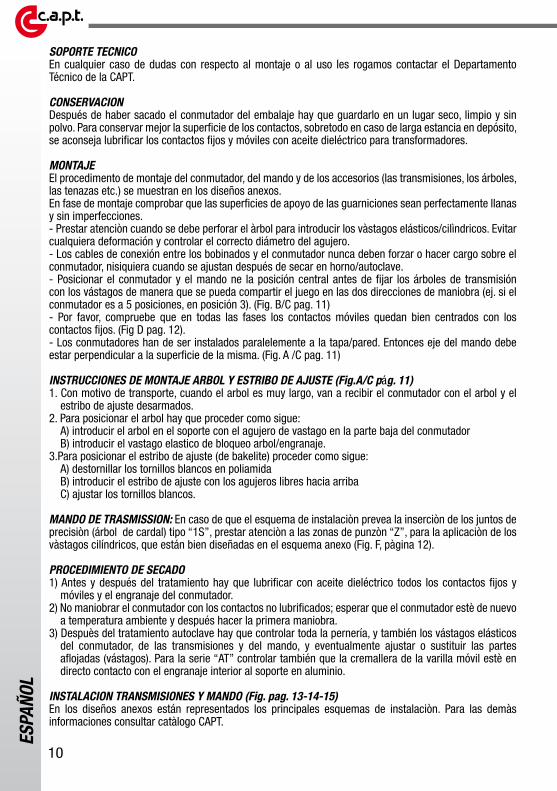
- Please check very carefully that in all phases, the moving contacts are well centered between the fixed contacts (Fig. D pag. 12).
- The tap changers have to be installed parallel with the tank wall/cover from which they exit. Therefore the driveshaft has to be perfectly perpendicular (Fig. A /C pag. 11).
SHAFT AND CLAMP MOUNTING INSTRUCTIONS (Fig. A/C pag. 11)1. For transport reason, when shaft is very long, you receive this tap changer with shaft and clamp
dissassembled.2. To position the shaft you have to procede as follows:
A) Insert the shaft inside support with pin hole in the below side of tap changer.B) Insert the elastic pin to block shaft/gear.
3. To position the clamp proceding as follows:A) Unscrew the white bolts and nuts in polyammideB) Insert the clamp with free holes in the top sideC) Screw the white bolts and nuts.
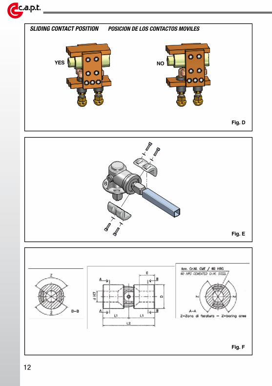
INDIRECT TRANSMISSION:In the case the assembly diagram instructions call for the use of universal type “1S” joints, pay great attention to the drilled sections “Z” where the cylinder pins are inserted. These pins are highlighted in the enclosed diagram (see fig. F page 12)
DRYING PROCESS1) Before and after the treatment is necessary to lubricate all fixing and moving contacts and the gear of tap changer with dielectric oil.2) Do not manoeuvre the tap changer when contacts are not lubricated, especially if the temperature of tap changer is hotter than ambient temperature. 3) After treatment is indispensable check the tap changer screws, bolts and nuts, including the elastic pins of tap changer, bevel gears and drive and if necessary screw the loosened parts or replace (pins). For series “at” check also that the rack of bakelite moving rod touch the gear inside the aluminium support. In case is necessary unscrew a bit the bolt and push the brass cylinder.
ASSEMBLY OF CONTROL DEVICE WITH INDIRECT TRANSMISSION (Fig. pag. 13-14-15)In the enclosed design-instruction booklet the main assembly phases are shown.Consult the CAPT catalogue for further information.

7
ESPA
ÑOL
CARACTERISTICAS PRINCIPALES Este es un conmutador fuera de tensión . Esto signifíca que NO DEBE maniobrarse cuando el transformador está en presencia de tensión.
DIMENSIONES Las dimensiones indicadas en caso de disegño anexo son todas en mm.
ACEITE MINERAL PARA TRANSFORMADORESTodos los conmutadores fuera de tensión de nuestra producción se consideran conformes a funcionar en aceite para transformadores según las normas IEC 60296.Para otros aceites o líquidos aislantes como el aceite silicónico aceites sintéticos y aceites vegetales deben consultar el departamento técnico de CAPT para comprobar que las carácteristicas del conmutador sean conformes al intento.
MATERIAL DE AISLAMIENTOEl material aislante utilizado es Bakelite (láminas de papel en pura celulosa con resinas fenólicas) en clase térmica “E”.
GUARNICIONESLas guarniciones estandard incluidas por CAPT para todos los mandos son del tipo NBR para el aceite de los transformadores y para temperaturas del líquido aislante comprendidas entre 25°C y +100°C y para temperaturas del aire comprendidas entre 25°C y +40°C, según las normas IEC 60214-1/2. Se pueden pedir guarniciones de varios tipos con mesclas que pueden soportar temperaturs màs bajas hasta -55°C y màs altas hasta +200°C.Estas guarniciones, siempre para aceite para transformadores y/o para aceites especiales , pueden ser del tipo HNBR, VITON, en GOMA SILICONICA, etcetera y pueden soportar las condiciones ambientales más extremas como clima tropical y clima ártico.
TEMPERATURA DE SECADOEn el proceso de secado de la parte activa del transformador, por parte de los constructores, se utilizan varios metodos: tratamientos en horno al vacío en autoclave, vapour-phase y otros. En este proceso usualmente se incluye el conmutador también. La temperatura máxima que CAPT recomienda para sus conmutadores es de 100120°C durante un periodo máximo de 24÷36h.
PROCESO DE SECADO CON TRANSMISIONES O MANDOSEs mejor relizar este proceso con el conmutador montado pero sin transmisiones y mandos. En el caso de que esto sea imposible es importante no superar los valores de tratamiento ya referidos. Cuando los mandos son completos de micro-interruptores para el bloqueo eléctrico de los seccionadores del transformador y/o para la transmisión a distancia de las posiciones o de otros componentes eléctricos se prefiere efectuar el proceso de secado del conmutador sin los mandos mismos;
CONTACTAR LA CAPTLes rogamos que contacten nuestros técnicos en los siguientes casos:• En caso de temperaturas o tiempos de secado superiores a los indicados en le precedente parrafo;• Para climas particolares, posibles tempestades de viento o arena; zona sísmicas; condiciones
ambientales extremas.
ADVERTENCIAS

8
ESPA
ÑOL
NORMA DE REFERENCIA: IEC60214-1 y IEC60214-2Por lo que se rifiere a lo no especificado quedan en vigencia las normas internacionales IEC60214-1 e IEC60214-2.
SOBRECARGASLos conmutadores CAPT pueden soportar todas las sobrecargas previstas por la norma IEC 60076-7.
Para maniobrar dentro de las diferentes posiciones, el operador tiene que proceder según lo indicado por abajo. La primera e indispensable operación es desconectar el transformador de la red abriendo los seccionadores sea por el lado AT sea por el lado BT, poniendolo así fuera de tensión.Después hay que quitar el candado(si hay uno), levantar el pomo de bloqueo mecánico que está encima del mando y dar vuelta al mando mismo hacia la nueva posición hasta el punto final. Volver a poner el pomo de bloqueo mecánico, introduciendo el perno en el agujero correspondiente a la nueva posición y, eventualmente, volver a poner el candado.
SERIE TIPO kV A N° posiciones
ATmando directo
AT/ ATC/ ATS24-36-52-72,5 120÷600
2÷9
ATSP / ATST / ATCT 2
MMT/ MC/ MS
24-36-52-72,5 120÷6002÷15
MSP / MST / MTCT 2
KKL/ KLD 24-36-52-72,5
800-15002÷15
KL1020 /KLST / KLCT 24 2
INFORMACIONES GENERALES
Los conmutadores de las tomas de corriente de la serie “AT-M-KL” son conmutadores lineares, para instalarse en aceite, al interior de la caja del trasformador, en posiciòn horizontal o vertical. Estan compuestos por un soporte (varilla) fijo en material aislante (Bakelite) en que se instalan los contactos fijos y por una parte móvil (varilla) aislante (Bakelite) en que se instalan los contactos móviles. Pueden ser trifásicos, monofásicos o bifásicos, simples, dobles o triples, con un único comando.MANDO DIRECTO: Pueden ser trifásicos, monofásicos o bifásicos, simples, dobles o triples, con un único comando. Todos los comandos manuales son predispuestos para el bloqueo mecánico con candado (1.12.120, 1.12.130, 1.12.212, 1.12.212BE) instalado directamente sobre la tapa.
MANDO DE TRASMISSION: Todos os comandos manuais são destinados ao bloqueio mecânico com cadeado (1.12.101, 1.12.104, 1.12.201, 1.12.202, 1.12.202-2, 1.12.202BE, 1.12.208, 1.12.209, 1.12.210, 1.12.401, 1.12.402, 1.12.408, 1.12.409, 1.12.501, 1.12.502) e estão instalados na parede da caixa do transformador. Alguns destes comandos dispõem também de um ou mais micro-interruptores para o bloqueio eléctrico dos seccionadores do transformador e para a transmissão remota das posições.
LAS CONEXIONES, LA PUESTA EN MARCHA DEL CUADRO DE MANDO, LAS MANIOBRAS Y LAS EVENTUALES SUCESIVAS INTERVENCIONES EN LA PARTE ELECTRICA NECESITAN EL TRABAJO DE PERSONAL PROFESIONAL Y AUTORIZADO.TODAS LAS MANIOBRAS DEBEN REALIZARSE SIEMPRE NO EN TENSION, CON EL TRANSFORMADOR DE-ENERGIZADO; NO SE DEBE TRABAJAR CON EL TRANSFORMADOR EN TENSION.
Clases de tensión, corrientes y n° de posiciones estandard:
OPERACIONES PARA EL USUARIO FINAL

9
ESPA
ÑOL
IMPORTANTE: HAY QUE HACER TODAS ESTAS MANIOBRAS FUERA DE TENSION.
CONECCIONES ELECTRICAS (DEL MANDO DE TRASMISSION)Cuando el mando de transmisión está dotado,ademàs de bloqueo mecànico (candado) incluso de micro-interruptores, conectar el terminal de conecciòn siguiendo el esquema eléctrico anexo.Hace falta conectar el bloqueo eléctrico sobretodo si el volante del mando da màs de una vuelta para cada posiciòn. Conectar también los micro-interruptores para la transmisiòn a distancia de las posiciones si hay unos.
MANTENIMIENTODurante el mantenimiento del transformador o como mínimo una vez al año, sobre todo si el cambiador de tomas siempre ha estado en la misma posición, le recomendamos (aunque no es obligatorio) realice como mínimo 10 operaciones a lo largo del rango de salidas con el transformador sin tensión. Esta acción se recomienda para garantizar una mayor duración del cambiador de tomas. Contribuye a evitar que se forme una película fina sobre la parte activa de los contactos fijos y móviles debida a la oxidación y a las impurezas dispersas en el aceite. Además, protege contra la formación de carbón “pirolítico” que puede producirse cuando los contactos permanecen en la misma posición durante largos periodos de tiempo, con el consiguiente aumento de la resistencia de contacto. Antes y después de esta acción de autolimpieza de los contactos, también puede resultar adecuado comprobar la eficiencia del cambiador de tomas mediante una medición de la resistencia (mΩ) de las fases.
SACAR EL TRANSFORMADOR DE LA CAJA
MANDO DIRECTO:No hay que quitar el conmutador de la tapa, solo, hay que bajar el nivel del aceite bajo el nivel superior de la caja. En el caso de conmutador con mando sobre la tapa, bajar el nivel del aceite bajo el nivel del mando.
MANDO DE TRASMISSION:No hace falta destacar el conmutador sólo hay que bajar el nivel del aceite hasta llegar bajo el nivel de introducciòn de la transmisiòn o del mando montado en la tapa o fijado en la parte superior o inferior de la pared caja del transformador.
PARA EL CONSTRUCTOR DEL TRANSFORMADOR
• El conmutador no es un producto terminado en sì;• Está sujeto a someterse a sucesivas manipulaciones y tratamientos;• Proceder a una instalación correcta;• Guardar en un lugar seco y sin polvo;• Manejar con cuidado;• La bakelite, el cartogeno y las partes en poliamida son materiales delicados y, por cierto, frágiles;• Lubrificar los contactos con aceite dieléctrico antes y después de los tratamientos;• No manejar cuando el conmutador està todavía caliente, recien sacado del horno;• Después del tratamiento, controlar y fijar todos los tornillos aflojados por efecto del estrecharse
de la bakelite deshidratados;• Fijar las conexiones de manera que el peso de las conexiones mismas no cargue encima del
conmutador;• Hay que instalar el conmutador como mandan los canones, controlando que los soportes y los
estribos intermedios de bakelite (si hay algunos) no vayan a forzar el conmutador
ADVERTENCIAS
10
ESPA
ÑOL
SOPORTE TECNICOEn cualquier caso de dudas con respecto al montaje o al uso les rogamos contactar el Departamento Técnico de la CAPT.
CONSERVACIONDespués de haber sacado el conmutador del embalaje hay que guardarlo en un lugar seco, limpio y sin polvo. Para conservar mejor la superficie de los contactos, sobretodo en caso de larga estancia en depósito, se aconseja lubrificar los contactos fijos y móviles con aceite dieléctrico para transformadores.
MONTAJEEl procedimento de montaje del conmutador, del mando y de los accesorios (las transmisiones, los árboles, las tenazas etc.) se muestran en los diseños anexos.En fase de montaje comprobar que las superficies de apoyo de las guarniciones sean perfectamente llanas y sin imperfecciones.- Prestar atenciòn cuando se debe perforar el àrbol para introducir los vàstagos elásticos/cilìndricos. Evitar cualquiera deformación y controlar el correcto diámetro del agujero.- Los cables de conexión entre los bobinados y el conmutador nunca deben forzar o hacer cargo sobre el conmutador, nisiquiera cuando se ajustan después de secar en horno/autoclave.- Posicionar el conmutador y el mando ne la posición central antes de fijar los árboles de transmisión con los vástagos de manera que se pueda compartir el juego en las dos direcciones de maniobra (ej. si el conmutador es a 5 posiciones, en posición 3). (Fig. B/C pag. 11)- Por favor, compruebe que en todas las fases los contactos móviles quedan bien centrados con los contactos fijos. (Fig D pag. 12).- Los conmutadores han de ser instalados paralelemente a la tapa/pared. Entonces eje del mando debe estar perpendicular a la superficie de la misma. (Fig. A /C pag. 11)
INSTRUCCIONES DE MONTAJE ARBOL Y ESTRIBO DE AJUSTE (Fig.A/C pág. 11)1. Con motivo de transporte, cuando el arbol es muy largo, van a recibir el conmutador con el arbol y el
estribo de ajuste desarmados.2. Para posicionar el arbol hay que proceder como sigue:
A) introducir el arbol en el soporte con el agujero de vastago en la parte baja del conmutadorB) introducir el vastago elastico de bloqueo arbol/engranaje.
3.Para posicionar el estribo de ajuste (de bakelite) proceder como sigue:A) destornillar los tornillos blancos en poliamidaB) introducir el estribo de ajuste con los agujeros libres hacia arribaC) ajustar los tornillos blancos.
MANDO DE TRASMISSION: En caso de que el esquema de instalaciòn prevea la inserciòn de los juntos de precisiòn (árbol de cardal) tipo “1S”, prestar atenciòn a las zonas de punzòn “Z”, para la aplicaciòn de los vàstagos cilíndricos, que están bien diseñadas en el esquema anexo (Fig. F, pàgina 12).
PROCEDIMIENTO DE SECADO1) Antes y después del tratamiento hay que lubrificar con aceite dieléctrico todos los contactos fijos y
móviles y el engranaje del conmutador.2) No maniobrar el conmutador con los contactos no lubrificados; esperar que el conmutador estè de nuevo
a temperatura ambiente y después hacer la primera maniobra.3) Despuès del tratamiento autoclave hay que controlar toda la pernería, y también los vástagos elásticos
del conmutador, de las transmisiones y del mando, y eventualmente ajustar o sustituir las partes aflojadas (vástagos). Para la serie “AT” controlar también que la cremallera de la varilla móvil estè en directo contacto con el engranaje interior al soporte en aluminio.
INSTALACION TRANSMISIONES Y MANDO (Fig. pag. 13-14-15)En los diseños anexos están representados los principales esquemas de instalaciòn. Para las demàs informaciones consultar catàlogo CAPT.

11
MOUNTING INSTRUCTIONS INSTRUCCIONES DE MONTAJE
Fig. C
A A
BB
YES
NO
Cover
1 2 3 4 5
1 2 3 4 5
Cover
Fig. BFig. A
YES
NO
YES
NO
Cover
Cover
12
SLIDING CONTACT POSITION POSICION DE LOS CONTACTOS MOVILES
Fig. F
YES NO
Fig. E
Fig. D

13
Fig. G
Fig. H
Fig. I

14
ASSEMBLY OF CONTROL DEVICE WITH INDIRECT TRANSMISSION
INSTALACION TRANSMISIONES Y MANDO
Fig. L
Fig. M

15
Fig. N
Fig. O

C.a.p.t. srl - Società con socio unico1° Plant: Via Postale Vecchia, 17 - 36070 - Trissino - VI - I taly
2° Plant: Via Arzignano, 43 - 36070 - Trissino - VI - I taly
tel. +39 0445 962297 fax +39 0445 490606E-mail: [email protected] www.capt.it