controlled flight into terrain near benalla – 28 july 2004 · controlled flight into terrain ....
TRANSCRIPT

ATSB TRANSPORT SAFETY REPORT Aviation Occurrence Investigation – AO-2008-050 (ATSB report 200402797 amended February 2009)
Final
Controlled Flight into Terrain Near Benalla – 28 July 2004
Piper PA31T Cheyenne, VH-TNP
ATSB report 200402797 (amended February 2009 - incorporating GPS dead reckoning navigation)

ATSB TRANSPORT SAFETY REPORT Aviation Occurrence Investigation
AO-2008-050 (ATSB report 200402797 amended February 2009)
Final
Controlled Flight into Terrain Near Benalla – 28 July 2004
Piper PA31T Cheyenne, VH-TNP
ATSB report 200402797 (amended February 2009 - incorporating GPS dead reckoning navigation)
Released in accordance with section 25 of the Transport Safety Investigation Act 2003
- i -

Published by: Australian Transport Safety Bureau Postal address: PO Box 967, Civic Square ACT 2608 Office location: 62 Northbourne Ave, Canberra City, Australian Capital Territory Telephone: 1800 020 616; from overseas + 61 2 6257 4150 Accident and incident notification: 1800 011 034 (24 hours) Facsimile: 02 6247 3117; from overseas + 61 2 6247 3117 E-mail: [email protected] Internet: www.atsb.gov.au
© Commonwealth of Australia 2009.
This work is copyright. In the interests of enhancing the value of the information contained in this publication you may copy, download, display, print, reproduce and distribute this material in unaltered form (retaining this notice). However, copyright in the material obtained from other agencies, private individuals or organisations, belongs to those agencies, individuals or organisations. Where you want to use their material you will need to contact them directly.
Subject to the provisions of the Copyright Act 1968, you must not make any other use of the material in this publication unless you have the permission of the Australian Transport Safety Bureau.
Please direct requests for further information or authorisation to: Commonwealth Copyright Administration, Copyright Law Branch Attorney-General’s Department, Robert Garran Offices, National Circuit, Barton ACT 2600 www.ag.gov.au/cca
ISBN and formal report title: see ‘Document retrieval information’ on page v.
- ii -

CONTENTS
THE AUSTRALIAN TRANSPORT SAFETY BUREAU ................................ vii
LIST OF ABBREVIATIONS ............................................................................. viii
EXECUTIVE SUMMARY ................................................................................... xi
1 FACTUAL INFORMATION ........................................................................ 1
1.1 History of the flight .............................................................................. 1 1.1.1 Witness information ............................................................ 4
1.2 Injuries to persons ................................................................................. 6
1.3 Damage to aircraft ................................................................................ 6
1.4 Other damage ........................................................................................ 6
1.5 Personnel information ........................................................................... 7 1.5.1 Pilot ..................................................................................... 7 1.5.2 Air traffic controllers .......................................................... 9
1.6 Aircraft information .............................................................................. 9 1.6.1 Aircraft airworthiness and maintenance ........................... 10 1.6.2 Selection of Navigation guidance ..................................... 11 1.6.3 GPS Navigation Receiver ................................................. 16 1.6.4 Radio Altimeter................................................................. 21
1.7 Meteorological information ................................................................ 23
1.8 Aids to navigation ............................................................................... 24 1.8.1 Global Navigation Satellite Systems ................................ 24 1.8.2 Ground-based navigation aids .......................................... 26
1.9 Communications ................................................................................. 28 1.9.1 Air traffic services (ATS) communications ...................... 28 1.9.2 Benalla CTAF ................................................................... 29
1.10 Aerodrome information ...................................................................... 29
1.11 Flight recorders ................................................................................... 29
1.12 Wreckage information ........................................................................ 30
1.13 Medical information ........................................................................... 32
1.14 Fire ...................................................................................................... 32
1.15 Survival aspects .................................................................................. 33
1.16 Tests and research ............................................................................... 33 1.16.1 GPS Simulator testing ....................................................... 33 1.16.2 GPS in-flight tests and evaluation .................................... 33
- iii -

1.16.3 Examination of the GPS data card .................................... 34 1.16.4 Pilot information on GPS dead reckoning ........................ 35 1.16.5 Terrain avoidance warning systems .................................. 35
1.17 Organisational and management information ..................................... 36 1.17.1 Air traffic services (ATS) ................................................. 36 1.17.2 Operator procedures .......................................................... 42
1.18 Additional information ....................................................................... 43 1.18.1 Radar data ......................................................................... 43 1.18.2 Other occurrences ............................................................. 46
2 ANALYSIS .................................................................................................... 47
2.1 Introduction ........................................................................................ 47
2.2 Flight management ............................................................................. 47 2.2.1 GPS dead reckoning navigation ........................................ 47 2.2.2 Possibility of a GPS error ................................................. 51 2.2.3 Possibility of an autoflight system fault............................ 51 2.2.4 Possibility of a mode selection error ................................. 51
2.3 Air traffic management ....................................................................... 52
2.4 Medical aspects ................................................................................... 54
2.5 Aircraft systems .................................................................................. 54
2.6 Summary ............................................................................................. 54
3 FINDINGS ..................................................................................................... 57
3.1 Context ................................................................................................ 57 3.1.1 Findings ............................................................................ 57
3.2 Significant factors ............................................................................... 58
4 SAFETY ACTIONS ..................................................................................... 59
4.1 Airservices Australia .......................................................................... 59
4.2 Australian Transport Safety Bureau ................................................... 60 4.2.1 Previous Safety Recommendations................................... 60 4.2.2 ATSB Safety Advisory Notice ......................................... 65 4.2.3 Safety research study ........................................................ 65
APPENDIX A : GPS navigation and Dead Reckoning ..................................... 67
APPENDIX B: submission to State Coroner’s Office of Victoria by an experienced pilot ........................................................................................... 71
APPENDIX C : GPS Pilot Aid issued by CASA in January 1998 ................... 94
Appendix D : sources and submissions ............................................................... 96
- iv -

DOCUMENT RETRIEVAL INFORMATION Report No. AO-2008-050
Publication date 2 March 2009
No. of pages 110
ISBN 978-1-921602-16-0
Publication title Controlled flight into terrain near Benalla, Vic. on 28 July 2004 Piper PA31T Cheyenne VH-TNP - ATSB report 200402797 (amended February 2009 - incorporating GPS dead reckoning navigation)
Prepared by Australian Transport Safety Bureau PO Box 967, Civic Square ACT 2608 Australia www.atsb.gov.au
Reference No. INFRA-08405
Acknowledgements Base topographic map in Figure 2 provided by the Country Fire Authority, Vic. ; Photograph in Figure 7 provided by John Saad ; Diagram of Trimble TNL 2101 Approach Plus receiver display unit from Trimble Pilot Guide ; Images in Figures 11 and 12 provided by the Australian Bureau of Meteorology ; Benalla Runway 26L GPS instrument approach chart in Figure 13 reproduced from Airservices Australia Aeronautical Information Publication – Australia ; Images of radar displays in Figures 19 and 20 provided by Airservices Australia.
Abstract On 28 July 2004, a Piper PA-31T Cheyenne, VH-TNP, with one pilot and five passengers, on a private, instrument flight rules flight from Bankstown to Benalla, collided with terrain 34 km south-east of Benalla. All occupants were fatally injured and the aircraft was destroyed by impact forces and fire. Instrument meteorological conditions existed at the time and the pilot had reported commencing a Global Positioning System (GPS) non-precision approach (NPA) to Benalla.
The experienced pilot was familiar with the aircraft and its navigation and autoflight systems. The flight did not follow the usual route to Benalla, but diverted south along the coast before tracking to the northernmost initial approach waypoint BLAED of the Benalla Runway 26L GPS NPA. While tracking to BLAED the aircraft diverged left of track, without the pilot being aware of the error. The air traffic control Route Adherence Monitoring (RAM) system triggered alerts, but controllers believed the aircraft was tracking to a different waypoint and did not question the pilot about the aircraft's position. The destruction of the aircraft navigation and flight control systems did not permit verification of their operational status. The investigation found that instructions to controllers relating to RAM alerts could be ambiguous. Actions were taken by Airservices Australia to enhance alerts and clarify controllers' responses to them.
The occurrence drew pilots' attention to the need to pay careful attention to the use of automated flight and navigation systems and also demonstrated the need for effective communication between controllers and pilots to clarify any apparent tracking anomalies. The Australian Transport Safety Bureau’s (ATSB) final report was released on 7 February 2006.
In July 2008, during the subsequent coronial inquest, additional information about the possibility of dead reckoning navigation by the GPS receiver was provided. The ATSB investigation was reopened to examine that possibility and an amended report issued. That investigation found that dead reckoning navigation could not be positively established as there were inconsistencies between dead reckoning principles and the recorded radar data. Neither could it reconcile how a
- v -

pilot would continue navigation by GPS with the alerts and warnings provided by the GPS receiver and the instrument indications. As a result of the reopened investigation, the ATSB issued a safety advisory notice alerting users of GPS navigation receivers to take appropriate action to ensure familiarity with dead-reckoning operation and any associated receiver-generated warning messages.
- vi -

THE AUSTRALIAN TRANSPORT SAFETY BUREAU
The Australian Transport Safety Bureau (ATSB) is an operationally independent multi-modal bureau within the Australian Government Department of Infrastructure, Transport, Regional Development and Local Government. ATSB investigations are independent of regulatory, operator or other external organisations.
The ATSB is responsible for investigating accidents and other transport safety matters involving civil aviation, marine and rail operations in Australia that fall within Commonwealth jurisdiction, as well as participating in overseas investigations involving Australian registered aircraft and ships. A primary concern is the safety of commercial transport, with particular regard to fare-paying passenger operations.
The ATSB performs its functions in accordance with the provisions of the Transport Safety Investigation Act 2003 and Regulations and, where applicable, relevant international agreements.
Purpose of safety investigations
The object of a safety investigation is to enhance safety. To reduce safety-related risk, ATSB investigations determine and communicate the safety factors related to the transport safety matter being investigated.
It is not the object of an investigation to determine blame or liability. However, an investigation report must include factual material of sufficient weight to support the analysis and findings. At all times the ATSB endeavours to balance the use of material that could imply adverse comment with the need to properly explain what happened, and why, in a fair and unbiased manner.
Developing safety action
Central to the ATSB’s investigation of transport safety matters is the early identification of safety issues in the transport environment. The ATSB prefers to encourage the relevant organisation(s) to proactively initiate safety action rather than release formal recommendations. However, depending on the level of risk associated with a safety issue and the extent of corrective action undertaken by the relevant organisation, a recommendation may be issued either during or at the end of an investigation.
The ATSB has decided that when safety recommendations are issued, they will focus on clearly describing the safety issue of concern, rather than providing instructions or opinions on the method of corrective action. As with equivalent overseas organisations, the ATSB has no power to implement its recommendations. It is a matter for the body to which an ATSB recommendation is directed (for example the relevant regulator in consultation with industry) to assess the costs and benefits of any particular means of addressing a safety issue.
About ATSB investigation reports: How investigation reports are organised and definitions of terms used in ATSB reports, such as safety factor, contributing safety factor and safety issue, are provided on the ATSB web site www.atsb.gov.au.
- vii -

LIST OF ABBREVIATIONS
AAIB Air Accidents Investigation Branch (UK)
ADC air data computer
AFCS automatic flight control system
AGL above ground level
AMSL above mean sea level
ASI airspeed indicator
ASRS Aviation Safety and Reporting System (NASA)
ATC Air traffic control
ATPL Airline Transport Pilot Licence
ATS Air traffic services
ATSB Australian Transport Safety Bureau
BEA Bureau d'Enquêtes et d'Analyses pour la sécuretié de l’aviation civile (France)
BoM Bureau of Meteorology
CASA Civil Aviation Safety Authority
CDI course-deviation indicator
COG course over ground
CVR cockpit voice recorder
DH decision height
DR dead (deduced) reckoning
DSTO Defence Science and Technology Organisation
FAA Federal Aviation Administration (USA)
FAF final approach fix
FAR Federal Aviation Regulation (USA)
FDI flight director indicator
FDR flight data recorder or flight data record
FL flight level
GNSS global navigation satellite system
GPS Global Positioning System
HDG heading
- viii -

HSI horizontal-situation indicator
IAF initial approach fix
IAS indicated airspeed
ICAO International Civil Aviation Organization
IFR instrument flight rules
ILS instrument landing system
IMC instrument meteorological conditions
Kg kilograms
KIAS indicated airspeed measured in kts
Kts knots (measurement of airspeed)
LED light-emitting diode
m metres
M magnetic (direction)
MAPt missed approach point
MDA minimum descent altitude (instrument approach)
MDH minimum descent height (instrument approach)
NAIPS National Aeronautical Information Processing System
NDB non directional beacon
NOTAM notice to airmen
NM nautical mile(s)
NPA non-precision approach
NTSB National Transportation Safety Board (USA)
PIC pilot in command
PED personal electronic devices
PNI pictorial navigation indicator
RAAF Royal Australian Air Force
RAM route adherence monitoring
RAIM receiver autonomous integrity monitoring
RDU receiver display unit
RNAV area navigation
RSR route surveillance radar
SAR Search and Rescue
- ix -

SOG speed over ground
TAAATS The Australian Advanced Air Traffic System
TAF aerodrome forecast
TAWS terrain awareness warning systems
TSO Technical Standard(s) Order
TAR terminal area radar
UTC coordinated universal time
VHF very high frequency
VOR VHF omnidirectional radio range
- x -

EXECUTIVE SUMMARY
At 0906 Eastern Standard Time on 28 July 2004, a Piper Aircraft Corporation PA-31T Cheyenne aircraft, registered VH-TNP, with one pilot and five passengers, departed Bankstown, New South Wales on a private, instrument flight rules (IFR) flight to Benalla, Victoria. Instrument meteorological conditions at the destination necessitated an instrument approach and the pilot reported commencing a Global Positioning System (GPS)1 non-precision approach (NPA) to Benalla. When the pilot had not reported landing at Benalla as expected, a search for the aircraft was commenced. Late that afternoon the crew of a search helicopter located the burning wreckage on the eastern slope of a tree covered ridge, approximately 34 km south-east of Benalla. All occupants were fatally injured and the aircraft was destroyed by impact forces and a post-impact fire.
The pilot, who was very experienced and familiar with the aircraft and its systems, had flown the route between Bankstown and Benalla at least once a week since 1988. The normal route overflew the ground-based navigation aids located at Marulan, Canberra and Albury. On this flight the pilot deviated from the planned route to track via the Jervis Bay area. From there the flight was cleared to track direct to the northernmost initial approach waypoint BLAED (ED) of the Benalla Runway 26L GPS NPA. Recorded radar data showed that the aircraft had not tracked to that point, but had diverged between 3.5 and 4 degrees left of the assigned track.
The amended route did not pass over any ground-based navigation aids, nor did Benalla have any ground-based navigation aids. Cloud cover over the latter part of the route obscured ground features, which would have prevented the pilot visually detecting the track error or monitoring the descent of the aircraft in relation to the terrain.
With the assistance of the Defence Science and Technology Organisation (DSTO), the ATSB conducted simulation testing of a similar GPS receiver type as in the accident aircraft. The results of that testing found that the GPS satellite signals would have provided the receiver with accurate navigation and that electronic interference was unlikely to produce a sustained GPS error.
The ATSB examined the process of information transfer to the data card and found that although the information stored in the data card of the aircraft’s GPS receiver was not current, the Benalla Runway 26L GPS approach coordinates had not changed.
The ATSB also sent the damaged GPS data card to the Bureau d'Enquêtes et d'Analyses pour la sécuretié de l’aviation civile (BEA) in France for examination in their laboratory. It was hoped that useful data might be extracted from the damaged card. In November 2005, the BEA reported that they had been unable to extract any useful data from the damaged card.
1 At the time of the occurrence, the term GPS was applied to all satellite navigation. Subsequently,
this was changed to the more accurate generic term Global Navigation Satellite Systems (GNSS) to avoid confusion with the name of the satellite system administered by the US Department of Defence. The term GPS is used throughout the report to reflect the term applicable at the time of the occurrence.
- xi -

Destruction of the aircraft’s navigation and automatic flight control systems prevented any examination. While the possibility of a defect within those systems could not be excluded, the investigation found that there were normally adequate warnings in the systems that should have alerted the pilot to a malfunction.
The GPS navigation information was independent of the automatic flight control system, and appears to have been used to accurately determine the descent point at 65 NM from ED. However, the divergence from the intended track and inconsistencies found in the accuracy of the distance and the tracking information from the recorded radar data, suggested that the navigation error was unlikely to result from an error within the GPS receiver or the database.
The oscillation observed on the recorded radar data of the aircraft’s track, and not present on previous flights, was significant. However, that could not be attributed solely to a pilot mode selection error. Nor could incorrect mode selection account for an error in the GPS guidance information provided to the pilot for the approach.
The aircraft’s radio altimeter should have provided a terrain warning if it had been correctly set but the pilot was known to disable it during flight using the circuit breaker, and may have forgotten to reset it before commencing the approach. Alternatively, had the radio altimeter been used the pilot may have thought the initial warning was spurious and not responded.
The aircraft was at FL220 in Class A airspace for most of the flight and consequently under air traffic control (ATC). The aircraft left controlled airspace when it descended through Class E and into Class G airspace, prior to commencing the GPS approach. Despite receiving two route adherence monitoring (RAM) alerts on the air situation displays, after the aircraft had been cleared to ED, air traffic controllers did not advise the pilot of the diverging track. The sector controller assumed that the aircraft was tracking to the southernmost initial approach waypoint BLAEG (EG). The pilot’s reputation for accurate tracking had reportedly influenced the controller’s assessment. A ‘halo effect’ and the effect of confirmation bias might have influenced the controller’s thinking and contributed to those decisions.
The Australian Transport Safety Bureau conducted a survey of controllers and examined the manner in which controllers monitored tracking accuracy of IFR aircraft and their responses to RAM alerts. The results of a survey of controllers found that they did not consistently advise pilots of tracking errors despite published instructions and training. As a consequence of this accident, the air traffic services (ATS) provider, Airservices Australia, consistent with its normal procedures, conducted an internal investigation. Its investigation report made seven recommendations that related to The Australian Advanced Air Traffic System (TAAATS) alerts refresher training, human factors awareness training, enhancements to TAAATS software, and greater clarity of instructions relating to aircraft track divergences and RAM alerts.
This occurrence has demonstrated the need for effective communication between controllers and pilots to clarify any apparent tracking anomalies. It also demonstrated the advisability for pilots to use more than a single source of position information before conducting an instrument approach.
There were several significant factors clearly identified by the investigation. The aircraft had diverged from the intended track, above cloud, without the pilot’s knowledge or without being advised by air traffic controllers that it had diverged.
- xii -

The route adherence monitoring alarm, a defence in the TAAATS system, was acknowledged by the controller without confirming with the pilot why the aircraft was diverging from the cleared route. The pilot commenced an approach believing that the aircraft was on the correct track and descended into terrain. The radio altimeter, fitted to the aircraft, did not provide the pilot with an adequate defence to prevent controlled flight into terrain (CFIT). Each of these significant factors points to safety action to reduce the chance of a similar accident in the future.
The investigation was severely hampered by the extent of destruction of the aircraft and the lack of recorded or other evidence. A recommendation was made to the Civil Aviation Safety Authority to review the requirements for the carriage of onboard flight recording devices in Australian aircraft.
As a consequence of this and other accidents involving controlled flight into terrain, the ATSB issued a safety recommendation to the Civil Aviation Safety Authority requesting a review of the requirements for terrain awareness warning systems in turbine-powered aeroplanes and helicopters. The full text of that safety recommendation can be found on the website www.atsb.gov.au of the ATSB
The ATSB also undertook a research study to examine pilot perceptions about global navigation satellite system approaches following this and other accidents where the aircraft involved were reported to be conducting GPS non-precision approaches. The results of that study were published in an ATSB report ‘Perceived Pilot Workload and Perceived Safety of RNAV (GNSS) Approaches’ released in December 2006. The report is available on the internet site www.atsb.gov.au of the ATSB.
In July 2008, following receipt of information relating to the dead reckoning (DR)2 operation of the GPS navigation receiver from the State Coroner’s Office of Victoria (Appendix B - Submission to the State Coroner’s Office of Victoria by an experienced pilot), the ATSB re-opened the investigation. That action was taken specifically to review the possibility that the GPS receiver had lost satellite signals and reverted to DR operation. A flight test undertaken for the State Coroner’s Office of Victoria, demonstrated that the GPS receiver would navigate using DR without the pilot having to manually enter groundspeed and track. That was contrary to the message on the GPS receiver’s display that prompted the pilot to enter those values, and was not stated in the pilot guide for the GPS receiver.
Although that test flight demonstrated that the GPS receiver would continue to display tracking guidance in DR navigation for the route and a GPS approach, if selected, it also showed that the receiver displayed messages alerting a pilot to the DR operation of the receiver. A video recording made during that demonstration did not show the panel-mounted annunciator lights or the NAV warning flag of the navigation indicator on the pilot’s instrument panel that alert pilots to the operating status of the GPS receiver.
Subsequent investigation by the ATSB found that the actual tracks and distances flown by the aircraft during the later stages of the flight could not be satisfactorily explained solely by a GPS receiver navigating by DR. A fault within the aircraft’s navigation or autoflight systems, mis-selection of those systems, or some
2 A form of navigation used to determine aircraft position by calculations of speed, course, time,
effect of wind, and previous known position (refer to Appendix A for a more detailed description).
- xiii -

- xiv -
combination of those factors, may have contributed to the accident. The absence of any technical or factual evidence to support a possible explanation resulted in the investigation being unable to make any positive findings.
The investigation found that there was little, if any, information about the in-flight DR operation of GPS receivers in any of the operating manuals published by manufacturers of GPS navigation receivers. Some users of these navigation receivers may not have been aware that the GPS receiver display unit would provide tracking guidance, including the legs of a GPS instrument approach, during DR navigation. This is a safety issue.
As a result of the re-opened investigation examining the possibility of DR navigation being a factor in the accident, the ATSB amended its original report. Those amendments more fully explained the operation of GPS receivers in DR navigation for the broader education of users of all GPS navigation receivers and included a safety advisory notice alerting users of GPS navigation receivers to take appropriate action to ensure familiarity with dead-reckoning operation and any associated receiver-generated warning messages.

1 FACTUAL INFORMATION
1.1 History of the flight At 0906 Eastern Standard Time3 on 28 July 2004, a Piper Aircraft Corporation PA-31T Cheyenne aircraft, registered VH-TNP (TNP), with one pilot and five passengers on board, departed Bankstown, NSW on a private flight to Benalla, Vic. The pilot had submitted an instrument flight rules (IFR) flight plan for the flight to Benalla and return.
The plan was the same as those the pilot had previously submitted for flights to Benalla and it showed that the aircraft would track along the published airways routes and via ground-based navigation aids located at Marulan, Canberra and Albury (Figure 1). The plan did not indicate that the aircraft was equipped with a global positioning system (GPS) receiver approved for use as an en route navigation and instrument approach procedure aid.
At 0926, when the aircraft was about 20 NM past waypoint CORDO (30 NM south-south-west of Sydney) and at flight level (FL) 220, the pilot requested and was cleared by air traffic control (ATC) to track via Jervis Bay and then via Canberra to rejoin the flight planned route. The pilot gave no reason for the change to the flight planned route, but it was possibly in response to a passenger request made sometime after boarding the aircraft.
At 0943, as the aircraft tracked south of Jervis Bay, a route adherence monitoring (RAM)4 alert activated on the Wollongong Sector air traffic controller’s air situation display. The RAM alert occurred because TAAATS5 detected the aircraft outside the RAM parameters. The controller was aware of the change in the aircraft’s track and acknowledged the RAM in accordance with procedures. The controller then asked the pilot to report when tracking direct to Canberra. The pilot acknowledged and requested a clearance to track direct to Albury.
At 0946, the aircraft was re-cleared direct to Albury and then via the flight planned route. The pilot read back the clearance. The recorded radar data showed that the aircraft turned right, but did not fly the direct track to Albury (Figure 1). The controller rerouted the flight data record6 from the aircraft’s position direct to Albury, thereby cancelling the RAM alert.
At 0948, the pilot was instructed to change frequency and to contact the Benalla Sector controller. At 0953, the Benalla Sector controller offered the pilot a clearance direct to Benalla. The pilot requested the direct track to waypoint BLAED
3 The 24-hour clock is used in this report. Eastern Standard Time (EST) was Coordinated Universal
Time (UTC) + 10 hours.
4 Route Adherence Monitoring is a controller advisory tool designed to assist in the early identification of a variation between the route contained in the flight data record and the actual route of an aircraft.
5 The Australian Advanced Air Traffic System (TAAATS).
6 Rerouting the flight data record means interacting with the system to amend the flight data record to ensure correct system processing.
- 1 -

- 2 -

(ED) at Benalla. That waypoint was the northernmost initial approach point for the Benalla Runway 26L GPS non-precision approach (NPA) (Figure 2).
The controller cleared the pilot to ED and then to Benalla, and then rerouted the flight data record from the aircraft’s position direct to ED. The pilot read back the clearance. However, radar data indicated that the aircraft did not track direct to ED, but diverged between 3.5 and 4 degrees left of the cleared track. The Benalla Sector controller did not question the pilot about the track discrepancy.
At about 1002 there was a controller-shift change at the Benalla Sector. The off-going Benalla Sector controller conducted a handover to the on-coming controller. The briefing given to the on-coming controller about the traffic situation included information that TNP was tracking direct to ED.
At 1022, in response to a request by the controller, the pilot advised that the flight’s planned descent point was 65 NM prior to ED.
At 1023, a second RAM alert activated on the air situation displays of both the Benalla and Snowy/Ovens Sector controllers. The Benalla Sector controller acknowledged7 the RAM alert immediately, which silenced the alarm at the console. Five seconds later, the Snowy/Ovens Sector controller accepted jurisdiction of the aircraft and acknowledged the same RAM alert on his console.
At 1025, the pilot contacted the Snowy/Ovens Sector controller after being instructed to change frequency. The controller did not cancel the RAM alert. The pilot was not advised of a tracking discrepancy.
At 1028, the pilot requested descent and was cleared to descend to 9,000 ft. Recorded radar Mode C8 data showed that the descent commenced at the previously advised descent point of 65 NM from ED. At 1033, when the aircraft was passing about 17,000 ft, the pilot was cleared to leave controlled airspace ondescent to Benalla via the GPS approach. The pilot correctly read back the clearance. Neither the controller nor the pilot mentioned the ED waypoint, but referred only to ‘the GPS approach’. Because he assumed that the aircraft was on track, the controller then rerouted the flight data record from the aircraft’s current position direct to ED. That action cancelled the second RAM alert (the first of significant relevance to the un
explained track deviation).
The position of the aircraft on the Snowy/Ovens Sector controller’s air situation display was east of ED and it was clearly not tracking to ED. The controller later stated that he believed that the pilot had always intended to track via EG (the southernmost waypoint of the Benalla Runway 26L GPS NPA) and not ED. However, the pilot had not indicated any change from his earlier stated intention to track to ED.
7 Acknowledging the RAM alert cancelled the aural alarm - but the visual alarm continued to alert
the controllers of the RAM until it was cancelled. Cancellation of the alert was actioned by either returning the aircraft to a point inside the RAM corridor, or re-routing the flight data record for the aircraft.
8 The encoding of an aircraft transponder signal with atmospheric pressure to permit inclusion of altitude information into the TAAATS radar.
- 3 -

The controller later explained that during previous regular flights of TNP to and from Benalla, he had observed the aircraft display consistent on-course tracking and he had every confidence in the pilot’s ability to navigate accurately.
At 1042, a third RAM alert activated as the aircraft was descending through about 6,100 ft and in Class G (uncontrolled) airspace. The controller rerouted the flight data record from the aircraft’s current position direct to EG and then acknowledged the RAM alert. The reroute and acknowledgement resolved the RAM alert, but again the pilot was not questioned or informed.
At 1045 the pilot reported commencing the GPS approach at Benalla. The pilot then reported that he was changing radio frequency to 122.5MHz, which was the Benalla common traffic advisory frequency (CTAF) and stated his intention to report again at 1055. The controller acknowledged the transmission and made a note of the nominated SARTIME9 on the air situation display. The radar indicated that the aircraft’s position was about 13 NM east of EG and maintaining 5,100 ft.
The radar showed that the aircraft then turned to the left and headed in a south-south-westerly direction at the same altitude, before disappearing from radar coverage at 1045. An employee of an operator, based at Benalla Airport, reported that at about 1055 the pilot broadcast on the Benalla CTAF that he was inbound for a Runway 26L GPS approach. At 1103, when the pilot did not report arrival at Benalla, the controller declared a search and rescue phase, and search action for the aircraft was commenced.
At 1725, a search helicopter located the burning wreckage of the aircraft on the eastern slope of a tree covered ridge in the Myrrhee area, approximately 34 km south-east of Benalla. The aircraft was destroyed by impact forces and a post-impact fire. There were no survivors.
1.1.1 Witness information
No one reported having seen the aircraft collide with the terrain. Several people near the accident site in the Myrrhee area and in the King Valley (4 NM east of the accident site) reported hearing a low-flying aircraft in the mist and cloud that morning (Figure 2). Another person at Edi Upper (6.5 NM east of the accident site) reported briefly seeing a twin-engine aircraft pass very low overhead in the mist and cloud, tracking in the direction of Myrrhee, a bearing of 256 degrees Magnetic. That sighting was reported to have been at some time before 1105. Other people near the aircraft’s probable flight path reported hearing an aircraft at times between 1030 and 1130. Only two people reported hearing an aircraft at a time that corresponded with the last radar return at 1045. One of those persons was located at Edi Upper and reported hearing an aircraft at about 1045 and the other person was in the King Valley. Another person, located south of Myrrhee, reported hearing the sound of an aircraft and after the sound had dissipated, heard a ‘crack’ like the sound of falling trees. At the time, that person had not connected those two sounds with the sound of an aircraft accident.
People in the King Valley and at Edi Upper described the noise of the aircraft as ‘…the engines were throttled right off as if it was coming in to land’ and ‘… the
9 SARTIME. The time nominated by a pilot for the initiation of search and rescue action if a report
has not been received by the nominated unit.
- 4 -

engines were not going hard’. They described the engine noise as constant, but loud due to its close proximity. Most reported the aircraft travelling in a westerly direction, but one person thought that the aircraft may have circled.
Figure 2: Locality map
- 5 -

1.2 Injuries to persons
Injuries Crew Passengers Others Total
Fatal 1 5 6
Serious
Minor
None
1.3 Damage to aircraft The aircraft was destroyed by impact forces and a post-impact fire.
Figure 3: View of the fire-damaged wreckage
1.4 Other damage Damage to natural vegetation in the vicinity of the accident site occurred due to the impact of the aircraft and post-impact fire.
- 6 -

1.5 Personnel information
1.5.1 Pilot
Type of licence Air Transport Pilot (Aeroplane) Licence (ATPL)
Medical certificate Class 1 and Class 2 (with vision conditions)
Age 68 years
Flying experience (total hours) 14,017
Hours on the type 3,10010
Hours flown in the last 24 hours 3.1
Hours flown in the last 7 days 9.6
Hours flown in the last 90 days 45
The last entry in the pilot’s log book was made on 7 April 2004. Calculations based on the pilot’s log book entries and company records indicated a total aeronautical experience of 14,017 hours. However, at the most recent medical examination in April 2004, the pilot’s total aeronautical experience was recorded as 15,600 hours. The investigation was unable to account for the discrepancy.
The pilot was endorsed on the Piper PA-31T Cheyenne aircraft and had flown TNP since 1988.
The pilot held a command instrument rating for multi-engine aeroplanes that was endorsed for GPS non-precision approaches. A record in the pilot’s log book dated 23 May 1996, certified use of the GPS under the instrument flight rules. A further record dated 29 March 2001, certified use of the GPS for non-precision approaches. The pilot had satisfactorily demonstrated GPS non-precision approaches at each subsequent instrument rating renewal. The pilot was reported to have routinely used the GPS for en-route navigation, including adjustments to the flight plan to accept direct tracking, without experiencing any uncertainty.
On 21 January 2004, the pilot attempted to renew that rating in TNP. The approved test officer reported that the pilot flew the required manoeuvres, including a GPS non-precision approach. That approach had been flown with the autopilot engaged and the pilot had satisfactorily demonstrated his ability to manipulate the autopilot system. However, the test officer reported that while the pilot’s performance was assessed as satisfactory on all but the mandatory non-directional beacon (NDB) instrument approach, his level of skill was less than that demonstrated on previous renewals. On 26 January 2004, flying with another test officer in a Beechcraft Duchess aircraft, the pilot satisfactorily completed an NDB instrument approach. The pilot’s records did not show if the required instrument flight recency had been met, but company records and recorded radar data for 7 July 2004 indicated that the
10 Estimate based on 16 years of average annual flying extracted from the pilot’s most recent log
book.
- 7 -

pilot had flown the Benalla Runway 26L GPS NPA within the 90 day currency requirement11.
The pilot held a valid Class 1 medical certificate. The most recent medical examination was conducted on 29 April 2004. The medical certification was valid for 12 months and was issued after assessment by the Aviation Medicine Section of the Civil Aviation Safety Authority (CASA), due to a controllable cardiac condition. The pilot’s medical history revealed non-cardiac related surgery in March 2002 that had precluded him from flying duties for 1 month. He had not reported any subsequent medical condition.
A review of the pilot’s medical records by an independent aviation medical specialist confirmed the assessment by CASA, that adequate monitoring and medication could control the pilot’s cardiac condition and thus satisfied the requirements for a Class 1 medical certificate.
Information about the activities of the pilot in the 72 hours prior to the accident was limited. There was no evidence to indicate any activity that would have affected the pilot’s ability to perform flight duties. On 27 July 2004, the pilot flew TNP from Bankstown to Benalla and Essendon, Victoria, returning to Bankstown via Benalla later in the day. The flying time was approximately 5.5 hours. The flight departed Bankstown at 0645 and returned at approximately 1900.
On 28 July 2004, the pilot was awake before 0600 to prepare for the flight to Benalla. There was no evidence to suggest that the pilot would not have had the opportunity to obtain 7.5 to 8 hours sleep the night before. Shortly before takeoff, another pilot spoke to the pilot. Following the accident that pilot reported that the pilot of TNP appeared to have been in good spirits.
Forensic examination determined that the pilot was seated in the front left seat. The passenger who was seated in the front right seat held a Commercial Pilot (Aeroplane) Licence, but was not endorsed on the aircraft type. He also held a Commercial Pilot (Helicopter) Licence with a Co-pilot (Helicopter) instrument rating endorsed for GPS arrival procedures12. Another passenger on the flight also held a current aircrew licence, but the seated position of that passenger could not be determined.
11 Civil Aviation Orders Sec. 40.2.1 Instrument Rating (Issue 3) para. 13.4A, required a pilot
conducting the procedure to have carried out not less than three GPS/NPAs using a GPS receiver that was the same as that fitted in the aircraft and, to have within the immediately preceding 6 months, carried out a GPS approach using a GPS receiver that was the same as that fitted to the aircraft. Renewal of the CIR required applicants to demonstrate proficiency using GPS/NPA either in flight or in a synthetic flight trainer every 12 months.
12 An arrival procedure where azimuth guidance is provided by ground-based aids, but distance information from either GPS or distance measuring equipment is used to provide obstacle clearance for descent to an aerodrome.
- 8 -

1.5.2 Air traffic controllers
Wollongong Sector controller
The Wollongong Sector controller was licenced in air traffic services in June 2004 and was appropriately qualified and current on that sector.
Benalla Sector controllers
The off-going Benalla Sector controller had 7 years experience as a controller and was appropriately qualified and current on that sector.
The on-coming Benalla Sector controller had 8 years experience as a controller and was appropriately qualified and current on that sector.
Snowy/Ovens Sector controller
The Snowy/Ovens Sector controller had 21 years experience as a controller and was appropriately qualified and current on the sectors he was managing at the time of the occurrence. The controller reported having completed an evening shift the previous day and on the day of the accident had commenced duty at 0630, in accordance with Airservices Australia rostering principles. He also reported being adequately rested.
1.6 Aircraft information
Manufacturer Piper Aircraft Corporation
Model PA 31T Cheyenne
Serial number 31T-7920026
Registration VH-TNP
Year of manufacture 1979
Certificate of airworthiness – (Initial) Issue date (18 December 1984)
Certificate of registration – (Initial) Issue date (18 December 1984)
Maintenance release Valid to 19 Jan 2005 or 5503 hours
Total time in service (TTIS) 5,496 hours
Allowable take-off weight 4,082 kg
Actual take-off weight 4,077 kg
Weight at occurrence 3,441 kg (estimated)
Allowable centre of gravity limits 3,200 to 3,550 mm aft of datum
Centre of gravity at occurrence Unknown
The aircraft was manufactured in 1979 in the US and remained US registered until 1984, when it was imported into Australia. Initially registered as VH-LJK, the registration was later changed to VH-TNP, with the certificate of registration being reissued on 17 July 1986. The aircraft was registered in the ‘Normal’ category.
- 9 -

The aircraft was owned by a corporation. One of the directors of the company held a pilot licence endorsed for the aircraft type and regularly flew the aircraft when accompanied by the accident pilot.
1.6.1 Aircraft airworthiness and maintenance
A review of the aircraft’s maintenance documentation indicated that the aircraft had been maintained to a system of maintenance approved by CASA. The aircraft had valid Certificates of Registration and Airworthiness. The current issue of the aircraft’s maintenance release was not found and was assumed to have been in the aircraft at the time of the accident, and destroyed by the post-impact fire.
A duplicate of the current maintenance release was held by the aircraft’s approved maintenance organisation. Although the duplicate listed scheduled maintenance requirements, it did not include certifications for daily inspections and in-service defects that may have occurred subsequent to the issue of the maintenance release. Those items would only have been entered on the document that was destroyed in the accident. The director who flew in the aircraft the previous day reported that there were no known aircraft defects on that flight.
There was no evidence found in the aircraft log books of any pre-existing defects that may have contributed to the accident. Records detailing avionics and electrical maintenance were limited, with only inspection/check items listed within scheduled maintenance shown in the aircraft log book. The aircraft maintenance organisation advised that avionics maintenance, other than the scheduled inspection/check tasks, was carried out by another organisation.
The organisation involved with the maintenance of avionics equipment on the aircraft advised they did not enter details into log books but issued a loose-leafed log book entry as a record of work for inclusion into the relevant log books by the owner or operator. Their records showed that the only maintenance performed since December 2003 was a check of the serviceability of the transponder, replacement of the turn co-ordinator and a lamp replacement in the navigation control unit.
The avionics organisation that installed the GPS receiver, and subsequently modified the unit, was no longer in existence. The technician who installed the unit supplied copies of some installation drawings for the TNL 2100 installation and recalled some details of the TNL2101 I/O Approach Plus installation, but the remaining documentation could not be located.
During the re-opened investigation, an avionics technician noted that with respect to GPS antenna maintenance generally, he had experienced isolated instances where internal corrosion to the GPS antenna was found after the GPS receiver was reported as faulty. Those instances were reported to have occurred to aircraft that were not hangared, and unlike TNP, were left outside exposed to the elements. Over a period of time, the sealant between the aircraft structure and the antenna deteriorated, allowing moisture to enter the unit, causing internal corrosion. The GPS receiver’s manufacturer reported that they were not aware of any instances where corrosion to a GPS antenna had resulted in other than decreased signal levels or a total failure of the receiver to track satellites. They reported testing a similar antenna by removing the protective outer casing, exposing the antenna pre-amplifier to the elements for many weeks and, apart from the obvious deterioration from exposure to the weather, were unable to detect any noticeable effect on its performance.
- 10 -

The pilot was also the maintenance controller for the aircraft. As such it was possible that the avionics log book (if in use) may have been in his possession or in the aircraft at the time of the accident. A search of the pilot’s home, the aircraft owner’s company office and the hangar, did not find any maintenance documentation relating to the aircraft.
1.6.2 Selection of Navigation guidance
The aircraft was equipped with a King KFC 300 automatic flight control system (AFCS) that was combined with a King KNR 665 Very High Frequency (VHF) area navigation (RNAV) system to provide the pilot with navigation and automatic flight control. The system was subsequently modified to incorporate a Trimble TNL2101 I/O Approach Plus GPS navigation receiver that provided an optional source of navigation information.
Navigation input to the automatic flight control system required a number of actions to select the navigation source and display the relevant information. It was possible to display navigation information on the pilot’s pictorial navigation indicator (PNI) that was different from the information steering the autopilot. For example, the course deviation indication on the PNI could display VHF Omnidirectional Range (VOR) navigation information while the autopilot was selected to GPS steering. Selector switches located on the lower centre panel (Figure 4) enabled selection of the desired functions. The switches illuminated to annunciate the selection.
Figure 4: Navigation function switching for the PNI and autopilot
Horizontal Situation Indicator display (HSI) selector switch HSI NAV (top), HSI GPS (lower)
Autopilot steering selector switch A/P HDG (top) A/P GPS (below)
- 11 -

When selected to provide navigation guidance, the GPS used the roll steering function13 of the automatic flight control system. That was engaged by selecting the automatic flight control system to the heading mode and the autopilot selector switch to GPS roll steering. That allowed the GPS to automatically navigate the aircraft direct to a GPS waypoint, or through a series of GPS waypoints in a selected flight plan route, including a GPS approach.
The course deviation indicator (CDI) on the PNI indicated the relative position of the aircraft to the left or right of a selected course. The course displayed on the PNI was manually selected from either the GPS or the VOR/Localiser by a separate selector switch (HSI Display). Selecting the HSI GPS displayed GPS navigation information.
Schematic diagrams in Figures 5 and 6 show the switching of the automatic flight control system in the heading mode.
13 Roll steering function provides GPS course guidance directly to the automatic flight control
system in the form of a ‘heading error’. Heading error was normally represented by the angular difference between the aircraft heading and the heading selected by the index (or bug) on the PNI.
- 12 -

Figure 5: Schematic diagram of AFCS heading mode selection for GPS roll steering
Automatic Flight Control System in Heading Select Mode with steering commands from GPS roll steering output and GPS CDI displayed on PNI.
- 13 -

- 14 -
Figure 6: Schematic diagram of AFCS heading mode selection for VHF navigation steering
Automatic Flight Control System in Heading Select Mode with steering commands from PNI (Heading Error – refer to Footnote 7) and VHF NAV displayed on PNI.

Figure 7: View of TNP’s instrument panel
Left instrument panel (Pilot) Centre instrument panel
Photograph courtesy John Saad
Horizontal situation indicator (HSI) and autopilot steering selector switches
Flight control mode annunciator panel
Flight Command Indicator (FCI) showing command bars (yellow)
Pictorial Navigation Indicator (PNI) with the Course Deviation Indicator (CDI) (yellow bar) and heading index (Bug) at top of dial (orange)
Vertical Navigation Computer with altitude select
Radio altimeter with decision height selector and index (yellow)
VHF Nav. 2 control panel. (Note: VHF Nav. 1 not in view)
GPS remote annunciator panel lights for : MSG (messages) RED, HLD (holding) AMBER, WPT (waypoint) WHITE and APR (approach) BLUE
GPS Receiver display unit (RDU) controls and display panel - data card inserted with blue tag.
- 15 -

1.6.3 GPS Navigation Receiver
The aircraft was equipped with a Trimble TNL 2101 I/O Approach Plus global positioning system (GPS) navigation receiver that conformed to the US Federal Aviation Administration (FAA) Technical Standard Order (TSO) C-129 (A1)14. The receiver was therefore approved for IFR use as a primary means15 navigatsystem for en-route navigation and non-precision approaches.
ion
The GPS receiver display unit (RDU) was installed in the centre instrument panel (Figure 7) to the right of the pilot’s instrument scan. During flight the small symbols and print on the RDU were not as readable as information on the PNI, directly in front of the pilot.
The panel-mounted RDU consisted of controls, a light-emitting diode (LED) display and a data card slot. The controls for the various operating modes consisted of push-buttons, known as function keys, and two concentric rotary selector knobs.
Figure 8: Trimble 2101 I/O Approach Plus GPS Navigation receiver
14 US Federal Aviation Administration Technical Standard Order C-129 (A1) - Airborne
supplemental navigation equipment using the global positioning system (GPS), February 1996.
15 A primary means navigation system is defined as a navigation system that, for a given operation or phase of flight, must meet accuracy and integrity requirements, but need not meet full availability and continuity of service requirements. Safety is achieved by either limiting flights to specific time periods, or through appropriate procedural restrictions and operational requirements.
- 16 -

The receiver display consisted of two data lines and an annunciator status line, beneath. The following is an example of a navigation mode display:
The upper data line shows the TO waypoint name, bearing and distance to that waypoint and the estimated time en-route. The lower data line shows the aircraft’s position relative to a desired track (either left or right of track as a course deviation graphic or CDI), and the current track and ground speed. The lower line displayed annunciations relating to the receiver’s operation.
The annunciator line contained the message (MSG), approach (APR), holding (HLD), parallel tracking (PTK) and WPT annunciators. The MSG, APR, HLD and WPT annunciators were duplicated as a set of remote light indicators located above the left instrument panel (Figure 7), directly in front of the pilot, to comply with the GPS installation regulatory guidelines16. That was necessitated by the location of the receiver unit on the lower central panel, to the right of the pilot’s primary field of view.
The MSG annunciator on the RDU and the corresponding panel-mounted light, flashed whenever a message was generated by the receiver. System and advisory messages appeared in text on the receiver’s display, such as:
Both the message annunciator and the panel light continued to flash until all messages were acknowledged by repeatedly pressing the MSG key on the RDU. Thereafter, both annunciator and panel light remained illuminated for as long as a message was valid. Subsequent messages were signalled by the message annunciator and panel light flashing again.
There was no aural warning associated with the message alerts generated by the TNL2101 I/O Approach Plus receiver.
The display selection menu within the GPS RDU permitted the selection of displays, such as a track error graphic, that removed the CDI from the RDU while navigating and yet still displayed distance to the waypoint.
The GPS RDU in TNP was connected to a Shadin ADC 200 air data computer that provided true airspeed and heading input. Using measurements from the aircraft’s pitot and static pressure systems and temperature probe, the ADC computed the relative air density and determined the true airspeed of the aircraft. The air data computer also received a heading reference input from the aircraft’s remote compass system.
TO YBNAA 239° 65 NM 0:55 [l l l l 0 l l l l l] TKl 243° 198KT MSG APR HLD PTK WPT
GPS: NOT AVAILABLE MSG APR HLD PTK WPT
16 Civil Aviation Advisory Publication 35-1(0), para. 49
- 17 -

When switched on, the RDU performed a series of self-test procedures. Checking the GPS receiver’s status prior to use for IFR flights was essential. For example, an expired data card would display the following message:
Regularly flown routes, such as between Bankstown and Benalla, could be stored in the flight plan mode of the receiver. To activate a stored flight plan, the pilot would select the desired flight plan and the navigation mode. That would provide tracking guidance between the automatically sequenced waypoints along the route. Typically, an approach procedure was added to the destination aerodrome of a stored route, so that when flying that route a pilot had only to select the transition waypoint for entry to the approach.
Within 30 NM of the destination airport, the receiver would enter terminal mode and automatic sequencing of the approach would commence. When the approach was enabled, the RDU would automatically default to the navigation display and cancel other functions such as the parallel track offset17, if engaged. The receiver would automatically sequence to the next waypoint in a series of programmed ‘TO-TO’ legs that displayed track guidance and distance to run to the next waypoint. Pilot interaction with the GPS RDU was thereby minimal during the approach.
A message normally appeared 15 to 20 seconds before waypoint passage. The waypoint annunciator on the RDU and the panel light would illuminate and a message on the RDU would advise the pilot to turn onto the next heading. On passing the waypoint, the next leg would be automatically displayed with the CDI indications and the distance to run to the next waypoint. Within 2 NM of the final approach fix, the approach annunciator would illuminate, indicating that receiver autonomous integrity monitoring (RAIM)18 was available and permitting descent to the minimum descent altitude (MDA). If the approach annunciator did not illuminate, descent to the MDA was not permitted and a missed approach was to be carried out.
The navigation tolerances for the GPS NPA were a maximum of a half scale deflection of the CDI scale. A missed approach was to be made if the aircraft was manoeuvred outside the tolerances.
If at any stage, before the missed approach point (MAPt), the pilot sees the ground and is confident of keeping it in sight, descent can continue visually to the runway.
The GPS approach could only be activated from the approach mode or the active flight plan mode. Although an approach waypoint could be selected from within the waypoints menu, selection would only allow the receiver to navigate to the
DATABASE OUT-OF-DATE EXPIRED 28 - JUN - 04 MSG APR HLD PTK WPT
17 A parallel offset function enabled manual selection to provide on-course indications while the
aircraft maintained an offset track parallel to a selected route or course. When parallel offset was selected the PTK annunciator remained illuminated.
18 RAIM UNAVAILABLE warning indicates that there are insufficient satellites for the receiver to perform RAIM - a process whereby the GPS receiver makes use of the redundant satellite information as a check on the integrity of the navigation solution.
- 18 -

waypoint and would not automatically sequence the approach. Therefore, it was likely that the procedure the pilot used for selecting the direct track to ED involved returning to the active flight plan page, selecting the destination Benalla, then the approach Runway 26L, and the desired ‘transition’ waypoint ED. Once selected, the ‘direct to’ function of the receiver would have provided navigation to the selected waypoint.
The GPS receiver’s manufacturer advised that during flight, the receiver used external speed and heading inputs from the ADC, with the GPS generated values of course over ground (COG) and speed over ground (SOG) to calculate a wind vector (speed and direction).
When insufficient satellite signals were available for navigation, the receiver reverted to dead reckoning (DR) navigation (Appendix A contains a detailed explanation of GPS DR navigation). A message alerted the pilot to dead reckoning navigation and prompted the pilot to manually enter groundspeed and track, as follows:
That message was displayed to enable a user to enter groundspeed and track when using the simulator function of the receiver or, in flight, to change those parameters if and when required. However, manually entering groundspeed and track was not necessary for DR operation of the receiver in-flight.
In DR operation, when the GPS derived COG and SOG values were unavailable, the receiver used the calculated wind vector from the last valid position solution with the true airspeed and heading inputs to compute a groundspeed and track in order to determine an estimated position. Any change in the wind vector from the last valid position solution would result in a corresponding error in the estimated position.
The GPS supplement for the aircraft's approved flight manual advised that "If the TNL-2101 (IO) Approach GPS, navigation is flagged19, the remaining operational navigation equipment must be used" and "If in the event the GPS is commanding the autopilot, and the system becomes flagged the autopilot 'fail-safes' into heading mode on the HSI". In effect, when the GPS receiver was navigating by DR, the navigation function switches for the PNI and autopilot would automatically revert to HSI - NAV and AP - HDG (Figure 6). The CDI on the PNI would then display tracking guidance from a selected VHF source, either VOR or Localiser/Instrument Landing System, if the selected ground-based aid was within range. When the aircraft was outside the range of a selected VHF navigation aid, the invalid navigation indications appeared on the PNI (Figure 9), i.e. the NAV warning flag displayed, the CDI centred20 and the TO/FROM indication was concealed.
DEAD RECKONING ENTER GS & TRACK MSG APR HLD PTK WPT
19 Term used to describe the appearance of the NAV warning flag (a small brightly-coloured red
plate) that appeared at the top left corner of the pictorial navigation indicator to give a visual warning to the loss of signal or a fault within the navigation source.
20 When the needle of the CDI is central, ie. no left or right deviation is indicated.
- 19 -

Figure 9: Pictorial Navigation Indicator showing the invalid navigation indications
The GPS RDU had an internal self-test function and monitored inputs, including the antenna signal. Any faults identified by the receiver generated a hierarchy of other messages alerting the pilot to system errors and internal faults. The loss of satellite signals initiated the following message:
Subsequent messages advised the pilot of DR navigation (see above) and the status of the navigation integrity.
The Aeronautical Information Publication 19.10 Operations without RAIM, instructed that when non-RAIM operation exceeded 10 minutes, the GPS information was to be considered unreliable and another means of navigation should be used until RAIM was restored and the aircraft re-established on track. It also instructed pilots, when flying in controlled airspace, to advise air traffic control of a loss of RAIM if:
(1) RAIM is lost for periods greater than 10 minutes, ...;or
(2) RAIM is not available when ATC requests GPS distance, …;or
(3) The GPS receiver is in DR mode, or experiences loss of navigation function, for more than one minute; or
(4) Indicated displacement from track centreline exceeds 2 NM.
NAV warningflag
TO/FROM indicators concealed
CDI needle centred
GPS: ANTENNA FAULT MSG APR HLD PTK WPT
- 20 -

The Civil Aviation Advisory Publication 179A-1(0) "Guidelines for Navigation Using Global Navigation Satellite System (GNSS)" published by the Civil Aviation Safety Authority (2002) stated:
The power and accuracy of GNSS encourages behaviours such as complacency, over-confidence and over-reliance. It is easy to assume that the machine is always right and lose situational awareness…
1.6.4 Radio Altimeter
The aircraft was equipped with a King KRA 405 radar21 altimeter. While a radio altimeter was standard fitment in many turbine-engine aircraft, there was no Australian regulatory requirement for such equipment to be installed in TNP. The radio altimeter displayed the aircraft’s height above ground level (AGL) directly below its flight path on a non-linear scale from 0 to 2,500 ft.
Using the radio altimeter decision height knob, a pilot could select a height that would, when the aircraft descended below that height, provide both a short aural tone and an advisory light on the pilot’s flight command indicator and the radio altimeter.
The investigation was unable to establish the pilot’s standard operating procedures for using the radio altimeter. Another pilot who regularly flew the aircraft reported that it was the pilot’s habit to pull22 the circuit breaker for the radio altimeter during flight and to reset it before commencing an approach. The investigation was unable to determine the reason for that action. It was reported that the pilot normally set a decision height of 600 ft AGL for the GPS approach to Benalla. The minimum descent altitude (MDA)23 for the Benalla Runway 26L GPS approach was 1,190 ft above mean sea level.24 That corresponded to a 621 ft height above the aerodrome.
The test officer who conducted the pilot’s previous command instrument rating renewals reported that the pilot had not used the radar altimeter on those occasions.
Due to impact and fire damage, the investigation was unable to determine if the radio altimeter was operating at the time of the accident, and if so, the decision height set for the approach.
The flight path in Figure 10 depicts Mode C radar data from the aircraft on 7 July 2004 when the pilot last flew the Benalla Runway 26L GPS NPA.
21 Radar altimeter was the manufacturer’s name for the instrument that provides a read-out of height
AGL by measuring the time delay between radio signals transmitted from the aircraft and reflected back from the ground below. The generic term radio altimeter is used throughout the report.
22 This action deactivated the radio altimeter.
23 Minimum Descent Altitude (MDA) is a specified altitude in a non-precision runway or circling approach below which descent may not be made without visual reference to the ground or water.
24 AMSL altitudes were obtained by setting the area QNH on an aircraft’s altimeter sub-scale setting (in hectopascal) to display the aerodrome elevation when on the ground.
- 21 -

Figure 10: GPS Approach to Runway 26L Benalla on 7 July 2004
Figure 11 indicates the radio altimeter alert envelope with a DH set to 600 ft in relation to the accident site and the ridge 3 NM to the east.
The descent flight path represented in Figure 11 was derived from information provided by witness reports, recorded radar data and the location of the accident site.
Figure 11: Representation of average descent on 28 July 2004
0
500
1000
1500
2000
2500
3000
3500
4000
4500
0 1 2 3 4 5 6 7 8 9 10 11 12 13 14 15 16 17
Track Distance along estimated flightpath (NM)
Alti
tude
abo
ve m
ean
sea
leve
l (fe
et)
5000
5500estimated approach
Ground elevation profile
Mode C Altitude of VH-TNP
Radio Altimeter Alert envelope <600' AGL
Radio Altimeter Alert envelope <600' AGL
Accident Site
The investigation was unable to confirm that the actual descent profile flown by the aircraft, because recorded radar data ceased at 1045 when the aircraft turned left at 5,100 ft.
- 22 -

1.7 Meteorological information Meteorological data from the Bureau of Meteorology (BoM) was electronically downloaded by the pilot from the Airservices Australia National Aeronautical Information Processing System (NAIPS) website at 0554 that morning. The area forecast (ARFOR) for Area 3025, valid from 0300 to 1500, forecast a cold front to move through the Benalla area at 1500. Ahead of the front, the weather was forecast to include patches of inland fog, with isolated showers and drizzle, and with significant low-level stratus cloud to exist west of the Great Dividing Range. Visibility was forecast as 500 m in fog, 3,000 m in drizzle and 4,000 m in rain. No aerodrome forecast was available for Benalla, but the pilot had obtained the Wangaratta aerodrome forecast (TAF), issued at 0513 and valid from 0600 until 1800. The Wangaratta TAF indicated broken26 cloud at 1,000 ft AGL and that temporary deterioration in conditions of up to 60 minutes duration could be expected throughout the forecast period with visibility reduced to 5,000 m in rain showers and broken cloud with a base of 800 ft AGL. The wind was forecast to be from a direction of 320 degrees at 5 kts.
The Area 30 ARFOR obtained by the pilot that morning forecast winds up to FL180. The forecast wind at FL 180 was 270 degrees True at 35 kts. It was not known if the pilot had checked the forecast winds at the planned cruising level of FL220. No record of Grid Point winds was retained for that day, but the upper air data for Melbourne at 1100 recorded a wind of 250 degrees True at 42 kts and for Wagga Wagga, 265 degrees True at 34 kts. A mean wind was calculated based on those recordings and used to determine the probable drift along the aircraft’s route. The lower level wind was forecast to be from a west, north-westerly direction at 25 kts.
Figure 12: Image of visible cloud at 0925 on 28 July 2004
Image taken from geostationary satellite GOES-9, Japan Meteorological Agency
25 The Area 30 forecast was applicable for the latter part of the flight near Benalla.
26 More than 4 OKTAS, equivalent to more than four eighths of the total sky area visible, obscured by cloud.
- 23 -

Satellite imagery from the BoM depicted the extent of cloud cover over south-eastern Australia at 0945 on 28 July 2004. The image showed that there was very little cloud east of the Great Dividing Range and extensive low-level cloud west of the range, including the Benalla area, consistent with the forecast.
Witnesses who heard the aircraft described the weather in the area as a low overcast that obscured all but the valleys. They reported light rain and drizzle in the area. The 1100 image from the BoM radar at Yarrawonga showed light to moderate rainfall returns across the area, but none in the area of the accident.
Figure 13: Yarrawonga radar image taken at 1100 on 28/07/04
Image provided by Bureau of Meteorology
Accident site
1.8 Aids to navigation
1.8.1 Global Navigation Satellite Systems
Background
Global navigation satellite systems (GNSS) are capable of extremely accurate position fixing. The first operational satellite system was the Global Positioning System (GPS) operated by the US Department of Defence. The Global Positioning System has been used in Australian aviation as a source of primary means
- 24 -

navigation since December 1995 for en-route IFR navigation. In January 1998 that approval was extended to its use for non-precision approaches. The approval permitted the establishment of instrument approaches at many locations, like Benalla, that were not served by ground-based navigation aids.
The Global Positioning System (GPS)
Satellite signals
Examination of the recorded satellite data for the duration and route of the accident flight found that there were no system anomalies and that the satellite constellation provided adequate signals for navigation. Receiver autonomous integrity monitoring (RAIM), that ensured the integrity of the position information for the continuation of a GPS non-precision approach, was available for the GPS approach at Benalla.
Waypoint co-ordinates
Waypoint co-ordinates for GPS approaches were stored in a navigation data base on a data card27, similar to a computer flash memory card. Those co-ordinates could not be edited. The data base was updated on a 28 day cycle from an internet account. The last update on the aircraft owners account occurred on 11 June 2004 when the AIRAC 0406 cycle, valid from 10 June to 8 July 2004, was downloaded. The co-ordinates for the Benalla Runway 26L GPS approach waypoints in the 0406 data cycle were found to be correct. That same data would have been used on previous flights, including the flight on 7 July 2004. Recorded radar data showed that the aircraft’s flight path on 7 July 2004 had conformed to the Benalla Runway 26L GPS approach, indicating that the waypoint coordinates were correct at that time. Laboratory examination of the damaged data card was unable to recover any data, (see Test and Research section 1.16.1).
Reference system
The GPS uses the WGS-84 datum28 as its geodetic referencing system. Other reference systems for non-aeronautical use can be manually selected from a menu within the GPS receiver. Tests conducted using different referencing systems found that selection of the most adverse reference system would result in a maximum error of less than one kilometre.
Interference
Interference from jamming or spoofing29 of the GPS signals was unlikely. There
27 A data card enabled a readily accessible means of updating the GPS data base at regular intervals.
The system also permitted the receiver manufacturer to make software upgrades without having to remove the receiver.
28 Datum : World Global System 1984. A mathematical model (ellipsoid or spheroid) which best represents all or one area of the earth’s surface.
29 Spoofing, in terms of GNSS, is the deliberate transmission of false signals that appear to be genuine, in order to deceive or confuse a GNSS receiver.
- 25 -

were no reports of interference to GPS signals from other aircraft. The Australian Department of Defence advised that they were unaware of any intended interference at that time.
Unintended signal interference from radio frequency transmissions emitted by personal electronic devices such as mobile phones, compact disc players or laptop computers can result in the loss of satellite signals and stop the GPS receiver from navigating. Six mobile phones were reported to have been on board the aircraft. Records of mobile phone use showed that the pilot made one short call to the company’s office in Benalla at 1008. Passengers who regularly travelled in the aircraft reported that mobile phones were not normally switched off and that they had never been suspected of interfering with the aircraft’s navigation equipment. The carriage of other personal electronic devices onboard the aircraft could not be confirmed.
GPS approach
The GPS non-precision approach to Runway 26L was aligned with the extended runway centre line that permitted a straight-in approach via a series of waypoints (Figure 14).
Each leg of the approach has a minimum altitude, published on the approach plate, to provide obstacle clearance along the approach path. A descent profile, in the form of a table with altitude against the distance to run to the missed approach point, provides descent profile guidance.
1.8.2 Ground-based navigation aids
The flight-planned route permitted a cross check of the GPS navigation position from ground-based navigation aids. It was reported that the pilot would track via the 221 radial from overhead the Albury VOR to ED for entry to a GPS approach at Benalla. However, it was also reported that terrain shielding resulted in a loss of signal from the Albury VOR below 11,000 ft. That would occur well to the east of ED.
The deviation from the planned route and subsequent tracking after the pilot was cleared to ED, did not take the aircraft directly over any ground-based navigation aids.
- 26 -

Figure 14: Benalla Runway 26L GPS instrument approach chart
ILLUSTRATIVE PURPOSES ONLY
NOT FOR OPERATIONAL USE
- 27 -
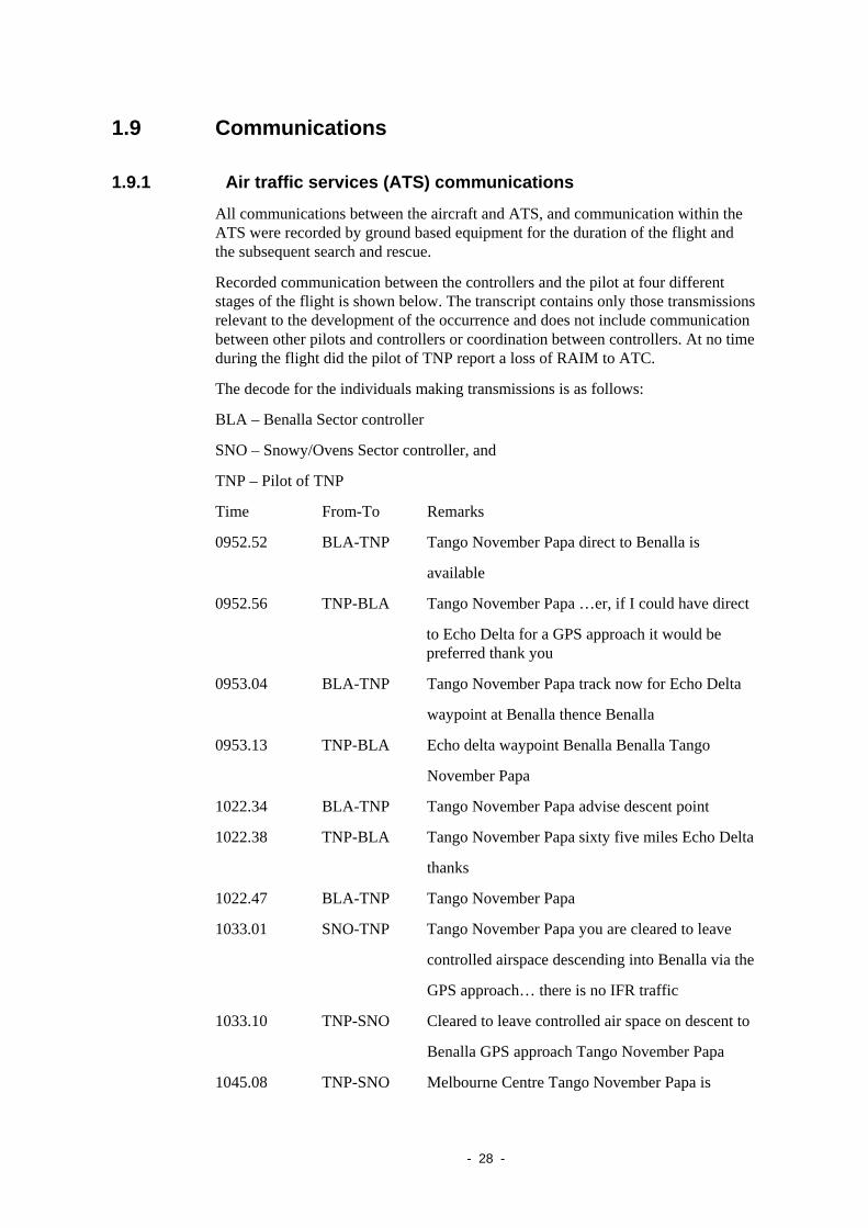
1.9 Communications
1.9.1 Air traffic services (ATS) communications
All communications between the aircraft and ATS, and communication within the ATS were recorded by ground based equipment for the duration of the flight and the subsequent search and rescue.
Recorded communication between the controllers and the pilot at four different stages of the flight is shown below. The transcript contains only those transmissions relevant to the development of the occurrence and does not include communication between other pilots and controllers or coordination between controllers. At no time during the flight did the pilot of TNP report a loss of RAIM to ATC.
The decode for the individuals making transmissions is as follows:
BLA – Benalla Sector controller
SNO – Snowy/Ovens Sector controller, and
TNP – Pilot of TNP
Time From-To Remarks
0952.52 BLA-TNP Tango November Papa direct to Benalla is
available
0952.56 TNP-BLA Tango November Papa …er, if I could have direct
to Echo Delta for a GPS approach it would be preferred thank you
0953.04 BLA-TNP Tango November Papa track now for Echo Delta
waypoint at Benalla thence Benalla
0953.13 TNP-BLA Echo delta waypoint Benalla Benalla Tango
November Papa
1022.34 BLA-TNP Tango November Papa advise descent point
1022.38 TNP-BLA Tango November Papa sixty five miles Echo Delta
thanks
1022.47 BLA-TNP Tango November Papa
1033.01 SNO-TNP Tango November Papa you are cleared to leave
controlled airspace descending into Benalla via the
GPS approach… there is no IFR traffic
1033.10 TNP-SNO Cleared to leave controlled air space on descent to
Benalla GPS approach Tango November Papa
1045.08 TNP-SNO Melbourne Centre Tango November Papa is
- 28 -

commencing GPS approach at Benalla changing to
one two two decimal five and we’ll call again at
time five five
1045.19 SNO-TNP Tango November Papa roger copy that and on the
ground or by time five five
1045.25 TNP-SNO Tango November Papa
The format of the transmissions was in accordance with the Aeronautical Information Publication and the Manual of Air Traffic Services requirements.
1.9.2 Benalla CTAF
A Common Traffic Advisory Frequency (CTAF) area extended for a radius of 10 NM around Benalla and to an altitude of 5,000 ft above mean sea level (AMSL). Pilots of radio-equipped aircraft operating to or from Benalla were required to make traffic advisory radio broadcasts on the published frequency of 122.5 MHz.
Transmissions made on the Benalla CTAF were not recorded. The frequency was monitored by an employee of an operator based at the aerodrome. That employee, who knew the pilot from his regular visits to Benalla, recognized his voice during the radio broadcast at 1055.
1.10 Aerodrome information The aerodrome was not served by any ground based navigation aids. Runway 26L was the main sealed runway. A parallel Runway 26R was a shorter, natural surface runway to the north of Runway 26L, used for glider operations. The aerodrome elevation was 569 ft AMSL.
1.11 Flight recorders The aircraft was not fitted with a flight data recorder (FDR) or a cockpit voice recorder (CVR), nor was there any legislated requirement for these to be fitted. Civil Aviation Order (CAO) 20.18 only required the fitting of an FDR and a CVR to turbine-powered aircraft with a maximum take-off weight greater than 5,700 kg and a CVR to certain categories of aircraft having a maximum take-off weight less than or equal to 5,700 kg.
Australian regulations requiring the carriage of an FDR and/or a CVR have not changed since 1988. During the interim period, advances in technology have resulted in solid-state recorders that are smaller, lighter, use less power and require less maintenance than those manufactured before 1988. In that time there has been considerable change to US and European requirements for the carriage of recording devices and the US National Transportation Safety Board (NTSB) has included improved recorder systems on its ‘Most Wanted’ list for many years. At least one large US general aviation aircraft manufacturer has indicated that it may incorporate recording devices in its aircraft as standard equipment.
- 29 -

The International Civil Aviation Organization (ICAO) Annex 6, Operation of Aircraft, incorporates standards and recommended practices. Recommendations for the operation of multi-engine turbine-powered aeroplanes under 5,700 kg maximum take-off weight, such as a Cheyenne, included the installation of a CVR and an FDR or a combination CVR/FDR.
Accident investigations in Australia involving multi-engine turbine-powered aircraft such as Beech 200 VH-SKC (Occurrence 200003771), Beech 200 VH-FMN (CVR only) (Occurrence 200105769), and although not turbine-powered Piper Chieftain VH-MZK (Occurrence 200002157) were limited by a lack of factual information that a CVR and FDR may have provided.
1.12 Wreckage information The burnt wreckage of TNP was located approximately 34 km south-east of Benalla. It was situated on the eastern face of a tree covered ridge at an elevation of 1,500 ft AMSL. The ridge was inclined at an angle of 22 degrees and aligned north-south, at right angles to the aircraft’s flight path. The wreckage was approximately 100 ft below the crest of the ridge.
The aircraft had cut a swath through the trees that extended for approximately 200 m from the first contact with the foliage to the main wreckage. The swath was angled upward at approximately 10 degrees on an alignment of 258 degrees. The aircraft attitude at the time of collision with the trees could not be determined.
The main wreckage came to rest upright on an easterly heading. The rear fuselage and empennage was nearby, having separated during the latter part of the impact sequence. Disintegration of the aircraft was consistent with successive impacts with trees. The force of the impact with one tree had rotated the aircraft through almost 180 degrees and severed the tail. Components of the airframe and segments of tree limbs up to 120 mm in diameter were found along the wreckage trail. The tree limbs were cut cleanly into short lengths with evidence of propeller contact. All control surfaces and trim tabs were found along the wreckage trail.
An intense fuel-fed fire developed after impact, which destroyed most of the aircraft fuselage, including the instrument panel and avionics. Little remained of the cockpit flight controls. The flap selector was found set to the first detent, consistent with the approach setting of 15 degrees and the landing gear selector was in the ‘gear down’ position. The landing gear was found in the extended position and the wing flap screw-jack extension corresponded with the approach setting of 15 degrees.
- 30 -

Figure 15: Wreckage site
The propellers and engines were examined on site. All displayed evidence of normal operation at the time of impact with the trees and ground and there was no evidence of any pre-impact failure. Damage to the engines and propellers was consistent with substantial power being delivered by the engines at impact.
Main Wreckage
Direction of flight
- 31 -

Figure 16: View looking back along the direction of flight
1.13 Medical information The autopsy did not preclude pilot incapacitation. However, independent specialist medical assessment found that there was no convincing evidence that the pilot had experienced in-flight incapacitation of either a subtle or sudden nature that would have contributed to the accident. The pilot’s toxicological report found no evidence that performance of flight crew duties would have been affected.
1.14 Fire The fire destroyed a significant part of the aircraft including the GPS and other navigation receivers, the autopilot system and its associated switches and wiring and the flight and navigation instruments.
There was no evidence of any in-flight fire.
- 32 -

Figure 17: The fire damaged GPS receiver and VHF Nav 2 receiver
GPS Receiver
VHF No. 2 Nav. receiver
1.15 Survival aspects The accident was not considered to be survivable due to impact forces and the post-impact fire.
1.16 Tests and research
1.16.1 GPS Simulator testing
Testing of a Trimble TNL 2101 receiver, similar to that used in TNP, was conducted using a GPS signal simulator at the Australian Department of Defence, Defence Science and Technology Organisation (DSTO) facility, using the orbital parameters of the GPS satellite constellation on the day of the accident flight. The simulations confirmed that:
• the satellite signals received by the GPS navigation receiver were accurate
• the GPS receiver correctly displayed the aircraft’s position on the flight path recorded by radar, and
• electronic interference was unlikely to produce a sustained GPS error.
1.16.2 GPS in-flight tests and evaluation
In 2008, flight testing of a Trimble TNL 2101 Approach Plus GPS navigation RDU for the State Coroner’s Office of Victoria (Appendix B - Submission to State Coroner’s Office of Victoria by an experienced pilot), demonstrated that the
- 33 -

receiver would navigate using DR without the pilot having to manually enter groundspeed and track. A message appearing on the receiver’s display prompted the user to enter groundspeed and track when the RDU reverted to DR navigation. The pilot guide for the TNL2101 Approach Plus also stated that groundspeed and track be entered for DR navigation.
Unlike TNP, the test RDU did not incorporate external speed and heading inputs. The demonstration was simulated by manually deselecting the satellite signals and forcing the receiver into DR operation, with an active route and GPS approach.
Video recordings of aspects of that test flight showed the GPS RDU, inset on an external view from the cockpit. That recording showed a receiver navigating by DR would display navigation guidance for a selected GPS approach. The recording showed that the RDU displayed the message alerting the pilot to DR operation of the receiver and prompting the pilot to enter groundspeed and track. Another message prompted the pilot to enter the barometric pressure and when entered it displayed the advice “APPROACH ENABLED”. Approaching each waypoint the WPT (waypoint) annunciator and panel light flashed, and a text message appeared on the receiver’s display prompting the pilot to intercept the next track.
That recording also showed that the APR (approach) annunciation on the GPS display did not appear within 2 NM of the final approach fix (FAF), due to the loss of RAIM, and that the HLD (hold) annunciation appeared at the FAF. Those indications were consistent with the description of a simulated GPS approach contained in the pilot’s guide. The recording did not show the PNI indications on the pilot’s instrument panel, or any external panel-mounted annunciator lights.
Subsequent testing of a Trimble TNL 2101 I/O Approach Plus navigation receiver was undertaken by the GPS receiver’s manufacturer at their facility. A satellite simulator reproduced the signals from the satellite constellation that existed during the accident flight. An external navigation test set generated speed and heading inputs to match the values of the accident flight (from recorded radar data) and a navigation indicator incorporating a CDI and warning flag, to display the receiver outputs to the external navigation instruments. That testing found that when simulated DR navigation was initiated, the messages and indications, both receiver and external CDI, to alert a pilot to DR navigation, displayed as required.
At the FAF, the receiver checks for RAIM and if not available, displays the message “RAIM UNAVAILABLE – EXECUTE MISSED APPROACH”. The manufacturer of the receiver advised that when the receiver was navigating in DR, that message does not display because the DR message remains valid and the MSG (message) annunciator remains illuminated.
1.16.3 Examination of the GPS data card
The fire damaged navigation data card, recovered from the GPS receiver, was sent to the Bureau d'Enquêtes et d'Analyses pour la Sécurité de l'Aviation Civile (BEA) in France for independent laboratory examination.
The ATSB requested that the laboratory attempt to extract the coordinates of the waypoints for the Benalla Runway 26L GPS NPA from the data card. Findings from those examinations indicated that high temperatures had probably degraded the memory data and therefore no data could be recovered.
- 34 -

1.16.4 Pilot information on GPS dead reckoning
The TNL 2101 I/O Approach Plus pilot guide, in common with most of the contemporary GPS receiver manufacturers’ guides, did not contain any explanatory information about in-flight DR navigation nor was there any description of the indications a pilot would expect to receive when this occurred. The only information provided to users about in-flight DR navigation appeared in the listed messages generated by the receiver. Significantly, there was no advice that the receiver would commence DR navigation without a pilot having to enter groundspeed and track, as prompted by the DR message.
Operation of the receiver during DR navigation did not require any pilot interaction. However, there was no explanation of in-flight DR navigation in either the pilot guide or the aeroplane flight manual supplement. There was no information that described the different manner in which DR navigation was calculated between receivers with external speed and heading input, such as in TNP, from those without.
The abnormal procedures section of the aircraft flight manual supplement for the Trimble TNL2101 I/O Approach navigation receiver made no reference to DR navigation and only advised that following a “RAIM NOT AVAILABLE” message, the receiver must not be used to provide distance information or if conducting an NPA, a missed approach procedure must be commenced immediately.
An examination of other manufacturers’ guides or manuals for these ‘first generation’30 GPS navigation receivers, found no descriptions of in-flight DR navigation. Instead, reference to DR navigation was found under demonstration or ‘take home’31 mode of operation that referred to simulation of the receiver’s operation and not to the in-flight operation of the receiver.
The published user guides of some later models of GPS receivers have incorporated information describing in-flight DR navigation. Those basic descriptions give pilots information about how and when the receiver reverts to DR navigation in flight and the messages and warnings displayed when the receiver is navigating by DR.
1.16.5 Terrain avoidance warning systems
In conjunction with this investigation, the ATSB reviewed a number of other accidents that occurred to Australian turbine-powered aircraft during the last decade and that involved controlled flight into terrain (CFIT). That review also compared Australian regulatory requirements for terrain awareness warning systems (TAWS) with the standards and recommended practices of the International Civil Aviation Organization (ICAO) and with those of other countries.
The ICAO recommendations and those of other accident investigation agencies had been made as a consequence of the availability of improved ground proximity warning system (GPWS) technology and the high number of aircraft accidents in which CFIT was a significant factor. Significantly, the review found that there had
30 Those GPS navigation receivers certified under TSO C129.
31 The manufacturer’s term for removal of the GPS receiver from an aircraft for data entry or practice on the ground.
- 35 -

been no reported CFIT accidents world-wide involving aircraft that had been fitted with TAWS. The review concluded that this occurrence, and the other accidents examined, probably would not have occurred if the aircraft involved had been equipped with TAWS.
The ATSB issued recommendations (Section 4.3) to CASA, for a review of the requirement for terrain awareness and warning systems for smaller turbine-powered aeroplanes and helicopters. The full text of the review can be found on the internet site www.atsb.gov.au for the ATSB.
1.17 Organisational and management information
1.17.1 Air traffic services (ATS)
The Australian Advanced Air Traffic System (TAAATS)
The TAAATS is the primary system for civil air traffic control in Australia. TAAATS integrates information from a range of sources, including radar, global positioning satellites, aircraft flight plans and pilot position reports. TAAATS is capable of processing radar signals from multiple sensors and combining the information to synthesise a track that is presented to the air traffic controller as the aircraft progresses along its flight path. The system also records the radar information received from each sensor as local track data, and the synthesised track as system track data.
Throughout the flight on 28 July 2004 the aircraft was tracked by various radar sensors. The sensors were; Sydney Terminal Area Radar (TAR), Mt Boyce Route Surveillance Radar (RSR), Mt Majura TAR, Mt Bobbara RSR, East Sale (RAAF) Radar and Mt Macedon RSR. All sensors were equipped with secondary surveillance radar with a rated coverage of 200 NM. Replies from the aircraft’s secondary surveillance radar transponder, as the aircraft descended east of Benalla, to the Mt Macedon RSR were subject to line-of-sight limitations.
Airservices Australia determined the division of Australian airspace for which controllers were responsible and the staffing levels required to provide the services. The Benalla Sector controller was responsible for aircraft separation services in the Benalla Sector airspace between FL 200 and FL 600 and all controlled airspace in the Eildon Weir Sector (Figure 18).
- 36 -

Figure 18: Benalla Sector controller’s airspace
The Snowy/Ovens Sector controller was responsible for a large geographical area, with varying vertical volumes of airspace and differing control functions, such as aircraft separation services within Class A and Class E airspace, and directed traffic information services in Class E and Class G (uncontrolled) airspace. The lower level airspace extended from ground level to FL200. The segment of upper level airspace extended to FL600 (Figure 19).
Figure 19: Snowy/Ovens Sector controller’s airspace
The default range setting for the Snowy/Ovens Sector air situation display was 390 NM. At that scale, a track deviation may not have been readily apparent to the controller. However, there was provision in the system for controllers to expand an area of the display to examine more closely an aircraft’s track.
- 37 -

The Australian Advanced Air Traffic System (TAAATS) alerting functions
The Australian Advanced Air Traffic System incorporated a wide range of in-built safety functions to automatically alert air traffic controllers to situations such as potential conflicts between aircraft, or deviations by aircraft from their assigned altitude or flight paths.
The route adherence monitor (RAM) is an alert that provides audio and visual cues to a controller when an aircraft diverges from its flight planned route. The significance of a RAM alert will vary depending on the type of airspace in which the aircraft is operating. For example, aircraft in Class G airspace are not subject to an airways clearance, but climb and cruise procedures require pilots to advise air traffic control if they deviate from a previously notified track. There is no requirement for pilots to advise deviations during descent and a controller is not required to query a pilot regarding a deviation in such circumstances.
The track width tolerance allowed by TAAATS before a RAM alert was triggered could be set at any value between 1 and 30 NM. At the time of the accident it was set to 15 NM. Hence, a RAM alert was activated if the radar track of the aircraft diverged more than 7.5 NM to the left or right of the flight planned route.
Route adherence monitor (RAM) procedures
Information in relation to Airservices RAM procedures at the time of the accident was contained in the Manual of Air Traffic Services (MATS) Sec. 2 8.7, dated 10 June 2004. The MATS instructions covered a number of aspects related to RAM alerts:
Route Adherence Monitoring (RAM)
2.8.7.1 On receipt of a RAM alert, the controller must provide tracking advice where necessary.
2.8.7.2 Where the aircraft's route is a known deviation from the flight plan, the FDR [flight data record] route must be modified to reflect the aircraft's actual route.
2.8.7.3 When the extent of an aircraft's deviation from the route held in the FDR is not known, such as during weather deviations, the controller should acknowledge the alarm and only modify the FDR when positive tracking advice is received from the pilot.
2.8.7.4 When an aircraft in RAM will not rejoin the FDR route prior to entering non-radar airspace, the extent of the deviation must be inserted in the LABEL DATA field. The symbology to be used for notifying a deviation from route is L for left, R for right or LR for left and right (e.g. 20L).
- 38 -

2.8.7.5 The RAM alert may be temporarily disabled at the Executive Controller position to alleviate extreme workload that could compromise safety and to assist in maintaining situational awareness. The planner32 associated with the EC position at which RAM is inhibited shall monitor aircraft exhibiting RAM alerts and assist the EC to maintain system information integrity as appropriate.
Airservices Australia TAAATS Alerts Review
In 2001, Airservices commenced a review of the general functioning and performance of safety alerts within TAAATS following feedback from controllers. The review found that the potential of the TAAATS alerts to provide a system defence against error or failure had not been achieved.
The Airservices report found that there were too many alerts, causing controller habituation33 to alerts. An alert was being acknowledged every 54 seconds in either the Brisbane or Melbourne Centre. The inability to distinguish aurally between alerts was adding to the habituation. The report found that 38 per cent of the responses to alerts resulted in an intentional violation of procedures.
In November 2003, the Board of Airservices Australia approved a TAAATS Alerts Review and Enhancement Project. Phase 1 of the software changes resulting from the project was delivered to Melbourne and Brisbane Centres nearly two months after the accident.
Controller response to RAM alerts during the accident flight
First RAM alert
At 0943, the RAM alert activated on the air situation display (ASD) of the Wollongong sector controller. The aircraft was in Class A airspace at FL220. The controller acknowledged the RAM and then asked the pilot to report when tracking direct to Canberra. The acknowledgement of the RAM silenced the aural alarm, but the visual alarm continued to be displayed until the controller rerouted the flight data record after the pilot read back the recleared amended route, direct to Albury. The aircraft then turned slightly left, but did not track toward Albury.
Second RAM alert
At 1023, the RAM alert activated on both the Benalla and Snowy/Ovens Sector controller’s ASDs when the aircraft was near Corryong (Figure 1) at FL220 in Class A airspace. The pilot had requested and been cleared to track direct to ED. The Benalla Sector controller acknowledged34 the alert, which silenced the
32 Planner : Controller position sometimes used to assist Executive Controller at times of high
workload.
33 Habituation : The act of becoming accustomed to something through prolonged and frequent exposure.
34 Acknowledgement of an alert in TAAATS is achieved by placing the cursor over the symbol and designating it with a mouse click.
- 39 -

associated audio alarm. The Snowy/Ovens Sector controller then accepted jurisdiction of the aircraft and acknowledged the RAM alert on his console. The Snowy/Ovens Sector controller believed that the aircraft was on track and acted to verify his understanding of the situation. He used the velocity vector35 of the ASD to compare the aircraft’s actual track with the planned track, as indicated by the route function (Figure 20)36. The controller did not recognise the deviation between the velocity vector and the route function. He also did not interpret the RAM alert as indicating that the aircraft was off track, or tracking incorrectly for waypoint ED.
Figure 20: PC Playback representation of TAAATS data at 1023
Aircraft symbol shortly before the second RAM alert was triggered. Velocity vector and route function selected.
At 1033, about 10 minutes after the RAM activated, the Snowy/Ovens Sector controller cancelled the alert by re-routing the aircraft on the ASD. The controller described his workload at this time as moderate, but with a greater than normal degree of complexity.
Third RAM alert
At 1042, the RAM alert again activated on the Snowy/Ovens Sector controller’s air situation display while the aircraft was descending in Class G airspace towards Benalla. At that point the distance from ED was much less and therefore the relative track error was more apparent (Figure 21).
35 Velocity vector. An electronic line attached to the radar track symbol that indicates the speed and
direction of the aircraft.
36 The use of PC replay pictures in figure 20 and 21 illustrates the difficulty that the controller would have experienced in observing the variation between the velocity vector and the route function. They may not be fully representative of the Air Situation Display modes and selections made by the air traffic controllers at the time.
- 40 -

Figure 21: PC Playback representation of TAAATS data at 1042:27
Aircraft symbol with velocity vector, after the aircraft was re-routed direct to BLAEG
The controller later reported that he had always believed the pilot was tracking to EG and that the aircraft was on track for that waypoint. In G Airspace, the controller was not required to have any further interaction with the pilot and did not ask for confirmation of the waypoint to which the pilot was tracking.
In contrast to the time taken to consider the previous RAM activation, where the controller considered the deviation for over ten minutes, the elapsed time between the third RAM alert activating and the controller rerouting the flight data record was only six seconds.
ATSB survey of controllers in relation to RAM alerts
Information about common practice by air traffic controllers in relation to RAM alerts was obtained by conducting a survey of controllers working in positions similar to those of the controllers that handled the accident flight. The survey was completed by 25 controllers; 12 from the Melbourne Centre and 13 from the Brisbane Centre. The survey was conducted in November 2004. Hence, some controllers may have been aware of the circumstances of the accident.
The survey found that controllers were responding on average to one RAM alert an hour. In 96% of all cases of RAM activations, the controllers were able to determine quite readily, the reason for the RAM alert. The controllers’ responses to RAM alerts, where the reason for the alert was unknown, were varied. When given a scenario similar to that involving the alerts that occurred during the accident flight, 83% of controllers reported that they would query a pilot. However, 32% also said that they would not challenge a pilot about track keeping if they felt that the reason for the alert was a minor infringement that was not of operational significance. Twenty eight per cent of controllers said that they did not know the Airservices documented instructions regarding the actions that a controller should take on receipt of a RAM alert.
Air traffic controller issues
A number of human factor issues may be relevant to the actions of the controller in handling the RAM alerts that occurred during the accident flight. Those issues include the ‘halo effect’, possible over-confidence in the accuracy of the GPS navigation system, and the effect of confirmation bias.
- 41 -

The term ‘halo effect’ refers to a tendency for a favourable impression of a person to influence the assessment of that person, including in possibly unrelated areas. The controller had become familiar with the pilot’s operations into Benalla through observing numerous flights to Benalla over several years. Based on those observations, the controller had a view of the pilot as being professional, efficient and unlikely to make mistakes.
A further factor in the controller’s decision-making with regard to the off-track indications provided by the RAM alerts may have been an underlying faith and over-confidence in the accuracy of the GPS navigation system, when compared with tracking using ground-based navigation aids.
The term ‘confirmation bias’ refers to a natural tendency of people to only search for or accept, information that confirms their present interpretation of a situation37. This leads to a tendency for people to accept information that confirms their current view of what is happening, and to downplay or discount evidence to the contrary. Therefore, if an individual’s mental model of a situation is wrong, they may tend to explain away any new information that indicates that they may be mistaken.
The effect of confirmation bias on decision-making is essentially unconscious. Hence, it can be quite difficult to recognise and counteract. For an individual to critically reappraise their interpretation of a situation, or to seek out contrary information, they must apply conscious effort.
1.17.2 Operator procedures
The investigation was unable to determine the procedures used by the pilot for the operation of the GPS, automatic flight control system and the radar altimeter. Copies of the flight manual supplements for the installed equipment, except the GPS receiver supplement, could not be found and may have been destroyed by the post-impact fire.
There were several occasions during the flight when the pilot’s response to the circumstances was not precise. Following the clearance to the Jervis Bay area, the pilot flew the aircraft south along the coast for a further 25 NM without advising the controller of his intentions until being prompted by the controller.
When cleared to Albury the aircraft turned and tracked well to the left of the required track. The track error was not detected and the aircraft flew for over six minutes on that track. Again, when cleared to track direct to ED, the aircraft changed track slightly to the right and not slightly left as would have been expected.
The pilot’s navigation procedure was reported as normally cross-referencing the GPS-defined route against the ground-based navigation aids. Although there were no ground-based navigation aids along the direct track to ED, the pilot apparently had not cross-referenced his GPS position to off-track aids, such as the Corryong NDB, which might have revealed the track error.
37 Bainbridge L (1999). Processes underlying human performance. In DJ Garland, JA Wise, & VD
Hopkin (Eds.), Handbook of aviation human factors (pp. 107-172). Mahwah, NJ: Lawrence Erlbaum.
- 42 -

- 43 -
1.18 Additional information
1.18.1 Radar data
System and local radar data relating to flights in TNP on 7 July and 28 July 2004 were examined. Recorded radar data on 28 July 2004 showed that the aircraft had diverged left from the planned track at the reporting point CORDO. A characteristic of that data, that was not present on previously recorded flights, was a consistent lateral oscillation of the aircraft’s track throughout the flight (Figure 22). That movement of up to approximately 0.2 NM either side of track was consistent with the hysteresis38 that can occur with heading coupling into the autopilot operation.
At 0946, after the pilot was cleared direct to Albury, the aircraft turned right onto a track that was between seven and eight degrees left of the direct track. At 0953, after the pilot was cleared direct to ED, the aircraft turned slightly right. The direct track to ED was 238 degrees Magnetic, but the aircraft diverged approximately 3.5 to 4 degrees left of the assigned track. That divergence was consistent with the calculated wind drift angle on that leg of the flight. In still air conditions a heading of 238 degrees M would have taken the aircraft to ED. A deviation of about 2 NM left of track was made south of Canberra. The pilot did not indicate to the controller any intention to make that deviation.
Recorded mode C radar data showed that the aircraft had accurately maintained FL220 until descent commenced at 65 NM from the waypoint ED.
After top of descent, the aircraft stabilised at an average rate of descent of 1,200 feet per minute and a consistent descent profile to where it levelled at 5,000 ft. Shortly after, it turned left and radar contact was lost.
Radar data from the flight on 7 July 200439, that had followed the pilot’s usual route from Bankstown to Benalla, did not exhibit the track oscillations seen on the accident flight (Figure 23).
38 Movement of the aircraft either side of a selected heading, resulting from tolerances within the
autopilot sensing and steering systems resulting in alternating successive corrections.
39 Used for comparison because a Benalla Runway 26L GPS approach was flown on that occasion.

Figure 22: Recorded radar data for 28 July 2004
Piper PA-31T Cheyenne, VH-TNP, Flight from Bankstown to Benalla 28 July 2004
0
40
80
120
160
200
240
280
320
360
09:0
0:00
09:0
5:00
09:1
0:00
09:1
5:00
09:2
0:00
09:2
5:00
09:3
0:00
09:3
5:00
09:4
0:00
09:4
5:00
09:5
0:00
09:5
5:00
10:0
0:00
10:0
5:00
10:1
0:00
10:1
5:00
10:2
0:00
10:2
5:00
10:3
0:00
10:3
5:00
10:4
0:00
10:4
5:00
Time (Eastern Standard)
Trac
k (d
egre
es T
rue)
/ G
roun
dspe
ed (k
nots
)
0
2000
4000
6000
8000
10000
12000
14000
16000
18000
20000
22000
24000
Mod
e C
Alti
tude
(fee
t ref
eren
ced
to 1
013H
Pa)
Track (calc)Groundspeed (calc)Mode C Alt
- 44 -

- 45 -
Piper PA-31T Cheyenne, VH-TNP, Flight from Bankstown to Benalla 7 July 2004
0
40
80
120
160
200
240
280
320
36007
:15:
00
07:2
0:00
07:2
5:00
07:3
0:00
07:3
5:00
07:4
0:00
07:4
5:00
07:5
0:00
07:5
5:00
08:0
0:00
08:0
5:00
08:1
0:00
08:1
5:00
08:2
0:00
08:2
5:00
08:3
0:00
08:3
5:00
08:4
0:00
08:4
5:00
08:5
0:00
08:5
5:00
09:0
0:00
Time (Eastern Standard)
Trac
k (d
egre
es T
rue)
/ G
roun
dspe
ed (k
nots
)
0
2000
4000
6000
8000
10000
12000
14000
16000
18000
20000
22000
24000
Mod
e C
Alti
tude
(fee
t ref
eren
ced
to 1
013H
Pa)
Groundspeed (calc)Track (calc)Mode C Alt
Figure 23: Recorded radar data for 7 July 2004

1.18.2 Other occurrences
A search of occurrence data bases held by the UK Air Accidents Investigation Branch and the US National Transportation Safety Board did not find any similar occurrences. There were numerous reports by crews experiencing GPS problems where receivers had stopped navigating for a period of time. Failure of the GPS receiver was reported to have been coincident with the discovery of mobile telephones or other personal electronic devices (PED) operating in the aircraft at the time. However, electronic interference from those devices was not established. One accident, where a pilot had turned onto a heading that was different from the GPS approach procedure being flown, was attributed to the pilot’s loss of situational awareness.
There was only one occurrence in the ATSB data base that presented similar characteristics to the accident flight. On 9 February 2003 (Occurrence 200300587) a Bombardier Dash 8 was observed on radar to diverge 9 NM left of track during a flight from Emerald to Brisbane. The aircraft’s crew reported that the aircraft was navigated by GPS and that the autopilot was engaged. No GPS warnings or error indications were observed and it was not determined if the receiver was navigating by DR. When the controller informed the crew of the track divergence, they reverted to ground-based navigation aids and continued to Brisbane. After landing, the GPS indicated a position 59 NM to the north of Brisbane.
The GPS receiver in the Dash 8 was a Trimble TNL 2101 I/O Approach receiver, similar to that installed in TNP. An examination of the receiver found no fault and after ground and air testing, the receiver was returned to service. The operator speculated that possible interference from a crew member’s active mobile phone may have caused the divergence. Subsequent testing in the same aircraft and with the same mobile phone, but using another identical GPS receiver, could not repeat the fault.
The operator advised that crews had reported numerous other GPS anomalies involving the Dash 8. Between February and September 2003, there were three occasions when the aircraft turned and tracked well left of the intended flight path while being navigated by GPS. In two of those occurrences, the cabin crew detected passengers using laptop computers and compact disc players. Following each of those events a functional test of the receiver was unable to detect any faults. The GPS receiver was replaced with a different unit each time, but the problems persisted until May 2005, when the operator replaced both the GPS receiver and the GPS antenna.
Subsequent testing, by the manufacturer of the receiver installed in the Dash 8 at the time of the first occurrence, was reported to have been unable to find any fault that would have affected the navigation resolution. No explanation was given for the receiver not displaying a warning during the event. The antenna was manufactured by a different manufacturer from that installed on TNP. It was tested and found to operate to its design specifications.
- 46 -

2 ANALYSIS
2.1 Introduction The experienced pilot, flying an apparently airworthy aircraft, descended and commenced an approach procedure at a location that was approximately 34 km south-east of waypoint ED, the pilot’s intended entry point to the GPS approach.
The analysis will therefore consider:
• if a malfunction within the aircraft’s automated flight and navigation systems or the pilot’s management of those systems resulted in a divergence from the intended track that was not recognised by the pilot
• why the air traffic control system did not inform the pilot that the aircraft was not tracking in accordance with the clearance and the pilot’s stated intentions.
2.2 Flight management The aircraft was primarily navigated by the GPS receiver. The circumstances relating to the operation of the navigation system and its integration with the automatic flight control system could not be established due to the destruction of the aircraft and its systems. Given the inbuilt protections within the GPS receiver and flight management system it is very unlikely that erroneous information would not be evident to the pilot. However, pilot mode confusion with the integrated automatic flight control system leading to a navigation error, could not be discounted.
2.2.1 GPS dead reckoning navigation
The flight path of the aircraft over the latter part of the flight, as established by superimposing the legs of a GPS approach over the last radar return, the accident site and the location of a witness who reported seeing the aircraft pass directly overhead (Figure 2), appeared to conform to the lateral profile of the Benalla Runway 26L GPS non-precision approach. In conjunction with the left turn recorded on radar, the pilot’s broadcast intention to make a GPS approach, and the configuration of the aircraft at impact, there can be little doubt that the pilot believed that he was flying that procedure, but unaware that he was 34 km from the correct location.
Conditions at the time precluded a visual approach and the only guidance for an instrument approach to Benalla in those conditions required GPS navigation. A possible explanation as to why the pilot was receiving apparent on-course indications at that distance from the correct approach path was that the GPS receiver had commenced navigating by DR at some earlier part of the flight, without the pilot being aware of it, and the wind drifting the aircraft off-course. However, for that explanation to be validated there would need to be consistency in the DR navigation seen in the successive phases of the flight. Additionally, there would need to be a corroborating explanation for the messages and warnings failing to alert the pilot to DR navigation.
- 47 -

Indications
Although it was demonstrated that a GPS receiver would continue to display tracking guidance in dead reckoning (DR) navigation for a route and a GPS approach, if selected, the receiver generated two messages, ‘RAIM UNAVAILABLE’ and ‘DEAD RECKONING …’ that alerted a pilot to DR navigation.
The aircraft was re-cleared from the coast to the flight planned route via a number of waypoints before being cleared direct to the GPS approach waypoint, BLAED. The pilot would have had to interact with the GPS navigation receiver, reselecting a new waypoint, each time. When a waypoint associated with a GPS NPA was selected, the RDU would have generated the message “RAIM UNAVAILABLE”, while navigating by dead-reckoning.
Should a pilot not consciously check and read those messages, there was a possibility of overlooking the DR navigation message, and continuing to follow the GPS-based guidance. However, in TNP, the NAV warning flag on the pictorial navigation indicator would have provided an unmistakable cue, as to the invalid GPS navigation (Figures 9 and 24). In addition, as there were no useable ground navigation aids, the CDI needle would have remained centred and the TO/FROM indication would have been obscured.
Figure 24: Aircraft panel depicting DR navigation indications
Remote annunciator panel lights showing MSG and HLD lights illuminated (no APR light) HSI displaying NAV warning flag TO/FROM CDI direction not displayed and CDI needle centred
GPS receiver display with MSG and HLD annunciators HSI selector switch with NAV selection displayed Autopilot steering switch with HDG selection displayed
Photograph courtesy of John Saad (modified to depict warning and alert status during DR navigation)
Flying an approach using the course deviation indicator on the GPS receiver display unit (RDU) would have been unusual and contrary to the requirements for approval that permitted GPS non-precision approaches to be flown. The pilot would have had to alternate his instrument scan between the flight instruments on the primary panel, directly in front of him, and the RDU to the right of that panel.
Additionally, the incorrect sequence of the different coloured panel-mounted annunciator lights would have also alerted the pilot to invalid navigation for continuation of the approach.
- 48 -

Flight path
During DR navigation, the wind vector used by the receiver would remain constant at the value calculated at the last valid position. The wind data provided by the Bureau of Meteorology showed that at times before and after the accident at locations surrounding the flight path, the wind at FL220 was from a westerly direction and estimated to have been between 34 and 42 kts.
Cruise
Although the deviation south of the cleared track was consistent with the drift the aircraft would have experienced at FL220, guidance provided by the receiver while navigating by DR should have resulted in little if any divergence from the original flight path unless a wind change occurred. The meteorological data indicated that the wind conditions at FL220 for the flight were relatively uniform.
The enhanced dead reckoning capabilities of the navigation receiver, with the true airspeed and heading input, would have shown a different characteristic following the small track deviation south of Canberra. Irrespective of whether the deviation was imposed by an atmospheric disturbance or by pilot input, the GPS would be expected to provide guidance to regain the original course as shown in Figure 25. The recorded radar data showed that after the deviation, the aircraft resumed the same heading, but was offset by about 2 NM and continued as such for a considerable time. In the en-route phase (5 NM CDI full-scale deflection), this course deviation would be represented by the CDI needle on the GPS RDU being displaced 2 dots right of centre.
The recorded radar data also displayed a significant difference in the characteristics of the aircraft’s tracking after this deviation. A consistent hysteresis observed in the aircraft’s track following that deviation was more likely explained by a changed selection in the automatic flight system, rather than any change to the GPS receiver navigation.
Figure 25: Diagram of track deviation south of Canberra
2 NM approx.
- 49 -

Descent
The descent commenced at 65 NM from the actual ED, the point nominated by the pilot. Assuming that the receiver was navigating by DR and had indicated 65 NM to ED at the top of descent, the receiver’s navigation computer would have used a groundspeed of 229 kts in order to arrive at the apparent ED position where, at 5,000 ft, the aircraft was seen on radar to turn left. Applying the wind vector for the cruise segment that was most likely to have been captured when the receiver commenced DR navigation, gave an airspeed of about 260 kts. The actual average groundspeed for the descent segment of 194 kts (calculated by using the distance flown, 55 NM, in the 17 minutes it took to descend from FL220 to 5,000 ft) equated to an actual headwind component of about 66 kts. A wind speed of this magnitude was not forecast nor was it consistent with the wind strengths derived from recorded data or the vector that would have been used in the DR navigation computations.
Approach
The Airservices Australia Benalla Runway 26L GPS approach chart (Figure 13), indicated that when the aircraft was on profile and at 1,500 ft, it should have been 2.5 NM from the missed approach waypoint (BLAEM), or 7.5 NM from the intermediate approach point (BLAEI). Measurement shows that the accident site was about 9.5 NM from the apparent BLAEI waypoint (Figure 2). From this it can be deduced that the groundspeed used in the GPS calculation was slower than the aircraft was actually travelling.
If the receiver was navigating by DR with a valid true airspeed input, a slower computed groundspeed could only result from a headwind component in the GPS computation that was greater than the actual headwind. Assuming that the approach was flown at the normal approach speed used by the pilot (125 kts indicated airspeed), then the headwind component of the wind vector used by the GPS in the DR calculation would have been about 31 kts40. A wind speed of this magnitude was consistent with the wind vector at altitude, but was not consistent with the wind vector that would have produced the observed descent segment of the flight.
Although DR navigation could provide a possible explanation for the aircraft having flown an apparent GPS approach, commencing at a point other than the correct location, the wind vector used by the GPS receiver in its computations during DR navigation should remain unchanged. However, analysis of the different phases of the flight concluded that there was no consistency in the wind vector, thereby precluding a positive verification of the GPS receiver navigating by DR.
There was also no evidence that messages and indications generated by the receiver to alert the pilot to DR navigation would not have displayed, in accordance with certification requirements. The probability of multiple failures masking the GPS receiver-generated warnings while reverting to DR navigation was considered to be extremely remote. In particular, it was difficult to reconcile that the pilot would not
40 This was based on zero wind during the GPS approach that from witness accounts of weather
conditions, none of whom mentioned winds of 30 kts at the time of the accident,. It was likely that there was some wind at the altitude that the aircraft was flying and that it was likely from a westerly direction, but the calculations showed that including any headwind in the actual conditions would increase the headwind that was used by the GPS in its DR calculations.
- 50 -

have observed the NAV warning on the PNI, along with the immobile and centred CDI needle and the obscured TO/FROM indication.
2.2.2 Possibility of a GPS error
A review of previously reported faults with GPS receivers indicated that the event was usually of a short-term duration and either the receiver stopped navigating or the error was large enough to be obvious. Only one previously reported event exhibited a diverging track, However it was not known if the receiver in that occurrence was navigating by DR. Although the GPS receiver in that event was the same type as fitted to TNP, subsequent testing by the operator and the GPS receiver’s manufacturer could not find any fault with the navigation performance of the GPS receiver or determine why it had not provided a warning.
No faults or navigation problems with the GPS receiver in TNP had been reported. It had operated normally, even when on previous flights passengers had carried mobile phones that were switched on. Although the data card was not current, it contained the same data that was used for previous flights and the waypoint coordinates had not changed.
2.2.3 Possibility of an autoflight system fault
Normally, the composite roll steering mode was used in TNP when tracking a GPS route. The recorded radar data displayed characteristics of the aircraft’s flight that were consistent with autopilot use. Significantly, track oscillations were observed that were not apparent in the recorded radar tracks of the aircraft’s previous flights. While they were symptomatic of a heading coupling to the autopilot, it is possible that this could have occurred in the navigation mode selection, and was coincidentally of the same magnitude as the rated stability of the heading mode.
A fault within the navigation system would have been expected to produce consistent tracking and distance errors. That consistency was not seen in the recorded radar data.
• When the pilot was cleared to track to Albury, the aircraft tracked well left of the direct track. When later cleared direct to ED the aircraft, instead of turning slightly left to track to the more southerly waypoint, the aircraft turned slightly right.
• The aircraft’s course from the last observation to the wreckage site was 7 degrees left of the published final approach track; nearly double the track error measured from where the pilot was cleared to track direct to ED.
• The aircraft commenced descent at 65 NM from the actual ED, the position nominated by the pilot as the top of descent point. However, it had travelled only 55 NM from that point at which it levelled at 5,100 ft and turned left, presumably to commence an approach procedure. That left turn was approximately 34 km south-east of ED.
2.2.4 Possibility of a mode selection error
The integrated GPS system was highly capable and complex, and depending on the circumstances of a pilot’s interaction, had the potential for mode selection error.
- 51 -

Although the pilot was experienced in operating those systems, an interruption to his normal interaction with the systems as a result of the diversion to the Jervis Bay area may have led to an undetected mode selection error or series of errors that resulted in the aircraft’s inaccurate navigation.
The procedures used by the pilot for the navigation and flight control of the aircraft could not be determined, but it would be normal practice to select the autopilot to GPS roll steering and to switch the pictorial navigation indicator (PNI) display to GPS. However, this may not have occurred due to the diversion via the Jervis Bay area or other distractions.
The complex switching of the automatic flight control and navigation systems could result in a selection of the ground-based navigation aid to the PNI, thus removing the GPS CDI information from the pilot’s primary flight instrument display.
The track anomaly that occurred after the pilot was cleared to Albury could not be explained. The direct track to ED could only have been navigated by using the GPS and did not require the aircraft to resume the active route within the receiver or to any of the planned waypoints along that route. The track did not take the aircraft over any ground-based aids, increasing the difficulty of detecting a track error by cross-reference to the GPS position. Terrain shielding was reported to have resulted in a loss of signal from the Albury VOR at 11,000 ft to the east of the ED position, making navigation by ground-based aids most unlikely. Cloud obscured ground features west of the Great Dividing Range that may otherwise have alerted the pilot to the diverging track and incorrect location during the subsequent descent.
The track from the position where the flight was cleared to ED diverged from the direct track, consistent with navigation guidance. In heading mode, without pilot intervention, any crosswind would have drifted the aircraft from the intended track. Although the effect of the calculated wind drift at FL220 was consistent with the track divergence of between 3.5 and 4 degrees left of the direct track, it was unlikely to have resulted in such a consistent flight path.
The accurate distance from ED at which the pilot commenced descent indicated that the ED waypoint was selected. It appeared that accurate distance information was displayed, but not tracking information. That could be explained by the selection of other GPS displays, such as the track error graphic, that displayed distance to the next waypoint, but not the CDI tracking graphic. However, it did not account for the left turn the aircraft made at 34 km south-east of ED and the subsequent flight path.
Although the flight path approximated that of a displaced Benalla Runway 26L GPS approach, the investigation was unable to determine what information had been displayed to the pilot for him to have commenced an approach at the wrong location.
2.3 Air traffic management In controlled airspace and especially in a radar environment, there is an expectation that deviation from track will be communicated to the pilot. The first route adherence monitor (RAM) alert was expected, given that a clearance was issued to the pilot to track from Jervis Bay to Canberra. However, the following two alerts were unexpected and required resolution with the pilot.
- 52 -

The Snowy/Ovens Sector controller twice received a RAM alert that the aircraft’s track differed from the flight planned data record. He acknowledged the first alert and, after about 10 minutes, re-routed the aircraft from its present location to ED using the re-route function in TAAATS, but did not confirm the route with the pilot. However, the second alert was cancelled after 6 seconds when the controller re-routed the aircraft to EG on his ASD.
On both occasions, despite the RAM alert and assessment of the displayed information, and without reference to the pilot, the controller concluded that the aircraft was on track. That was apparently based on experience that the aircraft always tracked accurately, and therefore the pilot must have intended to track for waypoint EG rather than ED. The controller’s rationalisation of the information was despite being aware that the pilot had not amended his earlier stated intention to track to ED.
When the controller re-routed the flight data record, he effectively confirmed within the air traffic control system that the pilot was tracking for EG. That action was based only on the controller’s unsupported assumption that it was the pilot’s intention to track to EG.
The natural bias for people to interpret information in a way that confirms their existing understanding of a situation may have influenced the way in which the controller dealt with the RAM alerts. That can apply regardless of available information to the contrary. If, after the activation of the RAM alerts, the controller had queried the pilot in relation to track keeping, then the pilot may have been afforded the opportunity to confirm the circumstances of the flight or to correct any navigation anomalies. Although the aircraft was outside controlled airspace at the time of the third RAM alert, it was a consequence of the same tracking error identified by the second RAM alert.
The results of the ATSB survey of RAM alerts suggest that while other controllers, in general, might have been more likely to query the pilot of the aircraft about track keeping, the actions of the Snowy/Ovens Sector controller fell within the range of responses received from a group of controllers. However, the information from the survey should be interpreted with caution given that it was conducted four months after the accident and some controllers may have been aware of circumstances relating to the accident.
Communication
During transmissions between the pilot and the Benalla Sector controller the pilot requested direct tracking to the waypoint ED and was cleared to that waypoint. Waypoint ED was again referred to when the pilot was requested to advise his top of descent point.
During subsequent transmissions between the pilot and the Snowy/Ovens Sector controller, the general term ‘Benalla GPS approach’ was used rather than any specific reference to the waypoint ED. Had either the pilot or the controller referred to waypoints ED or EG, it may have alerted them to the possibility that the aircraft was not on the intended track.
- 53 -

2.4 Medical aspects The specialist assessment of the pilot’s medical records confirmed that the pilot was no more likely to incur incapacitation, than were other pilots of the same age group.
The pilot’s communication with air traffic control throughout the flight, and his last broadcast on the Benalla Common Traffic Advisory Frequency (CTAF) just minutes before impact, did not suggest any abnormal circumstances. The wreckage examination showed that the aircraft was correctly configured for landing. Therefore, pilot incapacitation was considered to be an unlikely factor.
2.5 Aircraft systems
Radio altimeter
The installation of a radio altimeter provided a potential defence against controlled flight into terrain by alerting the pilot to the aircraft’s close proximity to the ground.
The investigation was unable to determine if the radio altimeter was operating during the flight. The pilot’s reported practice of pulling the radio altimeter circuit breaker involved the risk of forgetting to reset the circuit breaker prior to commencing an approach. High workload activity or distraction increased the probability that the circuit breaker could be forgotten.
Alternatively, had the radio altimeter been operating and the decision height set to 600 ft, a warning should have registered before the aircraft passed very low over terrain 3 NM east of the accident site on the adjacent ridge. A pilot accustomed to approaching Benalla from ED, over lower terrain, would not expect a warning at that part of the approach and at that height above the minimum descent altitude. Consequently, the pilot may have believed that the warning was spurious.
A subsequent warning triggered by the steeply rising terrain near the accident site may not have provided sufficient warning for effective terrain avoidance.
Terrain avoidance warning system
The installation of a Terrain Awareness Warning System would have provided greater warning of collision with terrain and could have prevented the accident.
2.6 Summary The investigation found that the accident was consistent with the controlled flight into terrain of a serviceable aircraft and an experienced pilot.
The investigation was unable to determine if the GPS receiver was navigating by dead reckoning. It was not possible to know if a malfunction within the aircraft’s navigation and automatic flight control system receiver was a factor in the development of the occurrence or if an undetected selection error had been made or if a combination of these events had occurred.
This occurrence has demonstrated the need for effective communication between controllers and pilots to clarify any apparent tracking anomalies. It also
- 54 -

- 55 -
demonstrated the need for pilots to avoid relying on a single source of position information, especially before conducting an instrument approach.


3 FINDINGS
3.1 Context From the evidence available, the following findings are made with respect to the controlled flight into terrain of Piper Cheyenne, VH-TNP near Benalla, and should not be read as apportioning blame or liability to any particular organisation or individual.
3.1.1 Findings
Aircraft
1. The aircraft was maintained in accordance with the manufacturer’s requirements, existing regulations and approved procedures.
2. The aircraft was appropriately equipped for IFR flight including the GPS receiver for conducting non-precision approaches.
3. There was no evidence of any mechanical defect or malfunction in the aircraft that could have contributed to the accident.
4. Destruction of the aircraft’s navigation and automatic flight control systems did not permit examination.
Air Traffic Services
1. The route adherence monitoring (RAM) alerts, triggered on the air situation displays by the aircraft’s diverging track, operated correctly.
Communication
1. The use of the generic term ‘GPS approach’ by the pilot and controller, rather than specific reference to ‘Echo Delta’ or ‘Echo Golf’, may not have alerted them to the possibility that the aircraft was not on the intended track.
Navigation system
1. The global positioning system provided adequate signals to the navigation receiver for the flight and non-precision approach.
2. The information stored in the data card of the aircraft’s GPS receiver was not current, but the Benalla Runway 26L GPS approach coordinates had not changed.
3. Navigation by dead reckoning (DR) of the GPS receiver could not be positively established. Although DR was a possible explanation for the aircraft’s flight path during the latter stages of the flight, there were inconsistencies between the recorded radar data and the principles of DR navigation.
- 57 -

In addition, in the event of DR navigation by the GPS receiver, it is unlikely that a pilot would not notice the range of messages and warnings presented by the receiver display unit and the GPS annunciator lights, or the various indications on the pictorial navigation indicator (PNI). As such, the possibility of a fault with the aircraft’s navigation or autoflight systems, a mis-selection of those systems, or some combination of those factors, is a more probable explanation.
4. The Pilots Guide for the TNL 2101 I/O Approach Plus GPS receiver, in common with most GPS manufacturer’s manuals, did not include information about in-flight dead reckoning navigation.
5. The installation of a Terrain Awareness Warning System would have provided greater warning of collision with terrain and could have prevented the accident.
3.2 Significant factors 1. The pilot was not aware that the aircraft had diverged from the intended
track.
2. The route flown did not pass over any ground-based navigation aids.
3. The sector controller did not advise the pilot of the divergence from the cleared track.
4. The sector controller twice cancelled the route adherence monitoring alerts without confirming the pilot’s tracking intentions.
5. Cloud precluded the pilot from detecting, by external visual cues, that the aircraft was not flying the intended track.
6. The pilot commenced the approach at an incorrect location.
7. The aircraft’s radio altimeter did not provide the pilot with an adequate defence to avoid collision with terrain.
8. The aircraft was not fitted with a terrain awareness warning system (TAWS).
- 58 -
4 SAFETY ACTIONS The safety issues identified during this investigation are listed in the Findings and Safety Actions sections of this report. The Australian Transport Safety Bureau (ATSB) expects that all safety issues identified by the investigation should be addressed by the relevant organisation(s). In addressing those issues, the ATSB prefers to encourage relevant organisation(s) to proactively initiate safety action, rather than to issue formal safety recommendations or safety advisory notices.
4.1 Airservices Australia An internal investigation was conducted by Airservices Australia into the air traffic system aspects of the accident. The investigation report made recommendations that related to The Australian Advanced Air Traffic System (TAAATS) Alerts refresher training, human factors awareness training, enhancements to TAAATS software, and greater clarity of instructions related to aircraft track deviation and route adherence monitoring (RAM) alerts. On 31 March 2005, Airservices Australia issued National Instruction NI 06/2005 Aircraft Track Deviations and RAM Alerts, to all air traffic service units. Included in that instruction were amendments to the Manual of Air Traffic Services (MATS) that clarified controllers’ actions in respect of aircraft track deviations.
An amendment to the MATS stated:
When ATC becomes aware of an aircraft diversion that has not been previously approved or advised, subsequent tracking intentions must be obtained from the pilot prior to modifying the FDR route.
During August 2005, Airservices Australia carried out a review of the recommendations and an assessment of the various stages of implementation of the recommendations.
The first recommendation related to TAAATS alerts refresher training and specified the development of refresher training modules for controllers that addressed the management of TAAATS alerts and alarms. Airservices advised that as of 1 October 2005, the majority of controllers had completed the refresher training module.
A recommendation for human factors awareness training resulted in the development of an information bulletin that was circulated amongst controllers in August 2005. That bulletin contained information relating to confirmation and expectation biases and used actual occurrences as examples to illustrate their application to ATS.
Development and implementation of a specific graphic tool that readily displays on a controller’s air situation display an aircraft's cleared route as recorded in the flight data record was also recommended. The software for that enhancement was undergoing development with implementation scheduled for early 2006. [Airservices Australia advised that this enhancement was incorporated into TAAATS in July 2007.]
The other recommendations related to aircraft deviations from planned or cleared routes. The review found that the Manual of Air Traffic Services (MATS) should be changed to provide improved definition of air traffic control requirements, in
- 59 -
accordance with those recommendations, by removing any ambiguity in the controller’s instructions relating to RAM alerts and clarification of controller responsibilities to general radar surveillance and aircraft deviations. Subsequent to the issue of National Instruction NI 06/2005, MATS was amended on 9 June 2005.
A recommendation that specific phraseology be developed for pilots commencing a GPS NPA was considered and, after consultation with CASA, was rejected.
4.2 Australian Transport Safety Bureau
4.2.1 Previous Safety Recommendations
Central to ATSB's investigation of aviation accidents and incidents is the early identification of safety deficiencies in the civil aviation environment. While the ATSB issues recommendations to regulatory authorities, operators, manufacturers or other agencies in order to address safety deficiencies, its preference is for industry organisations to make safety enhancements during the course of an investigation. The ATSB is pleased to report positive safety action in its final reports instead of needing to make formal recommendations. Recommendations may be issued in conjunction with ATSB reports or independently. A safety deficiency may lead to a number of similar recommendations, each issued to a different agency.
The ATSB does not have the resources to carry out a full cost-benefit analysis of every recommendation. The cost of any recommendation must always be balanced against its benefits to safety, and aviation safety involves the whole community. Such analysis is a matter for the body to which the recommendation is addressed (for example the Civil Aviation Safety Authority in consultation with the industry).
ATSB Safety Recommendation R20060008 issued 9 March 2006
The Australian Transport Safety Bureau recommends that the Civil Aviation Safety Authority review the requirements for Terrain Awareness Warning Systems for Australian registered turbine-powered aircraft below 5,700 kg, against international standards such as ICAO Annex 6 and regulations such as FAR 91.223, with the aim of reducing the potential for CFIT accidents.
The Civil Aviation Safety Authority should also consider the requirements for Terrain Awareness Warning Systems for Australian registered turbine-powered helicopters against the background of the US NTSB recommendation for the fitment to turbine-powered helicopters certificated to carry six or more passenger seats.
Responses
Response From: Civil Aviation Safety Authority, dated 16 August 2006
Response Text:
CASA accepts the recommendation and will take the following action:
- 60 -

CASA will consider various aspects in relation to the fitment of Terrain Awareness Warning Systems for Australian registered turbine-powered aircraft below 5700kgs, including:
• cost benefit analysis of costs to industry;
• how fitment would improve safety in this class of aircraft;
• CASA policy on fare paying passengers;
• impact on freight operators;
• training in the use of the equipment; and
• the lead time required prior to fitment.
ATSB response status: Closed - Accepted
Response From: Civil Aviation Safety Authority, dated 17 July 2007
Response Text:
In response to ATSB recommendation 20060008 in which CASA accepted the recommendation. I provide an update on CASA action in response to this recommendation.
CASA is investigating both the capital and installation cost of this equipment. CASA will then look at the applicability to the fleet and the safety benefits. This process should take 3-4 months.
ATSB response status: Closed - Accepted
ATSB Safety Recommendation R20060004 issued 7 February 2006
The Australian Transport Safety Bureau recommends that the Civil Aviation Safety Authority (CASA), review the requirements for the carriage of on-board recording devices in Australian registered aircraft as a consequence of technological developments.
Responses
Response from: Civil Aviation Safety Authority, dated 11 May 2006
Response Text:
The Civil Aviation Safety Authority will analyse the cost benefit of the recommendation regarding the carriage of on-board recording devices to this type of operation.
ATSB response status: Closed – Accepted
Response From: Civil Aviation Safety Authority dated 17 July 2007
Response Text:
- 61 -

On the issue of on board recording devices, this is a cost and maintenance burden with existing equipment. Low cost/new technology units are not currently available. CASA will continue to monitor this.
ATSB response status: Closed - Accepted
Response From: Civil Aviation Safety Authority, dated 07 September 2007
Response Text:
In reference to ATSB recommendation R20060004 (issued following the Benalla accident) on page 34 of the draft report [relating to 200502662]:
As you are aware, on 11 May 2006 CASA advised of an intention to conduct a cost/benefit analysis of the recommendation regarding the carriage of on-board recording devices to this type of operation.
I understand that CASA has previously investigated this matter and, based on the equipment available at the time, could not justify mandating carriage of recording devices on low capacity aircraft. However, given other priorities, this has not yet been confirmed by way of a cost/benefit analysis.
I have now directed that a cost/benefit analysis be undertaken. I expect to have a result before the end of the year and will forward the results to you.
ATSB response status: Closed - Accepted
Response From: Civil Aviation Safety Authority, dated 20 December 2007
Response Text:
I refer to the letter dated 11 October 2007 from the Deputy Director, Information and Investigations to General Manager, Corporate Relations[CASA], enclosing an advance copy of amended Transport Safety Investigation Report on the fatal accident involving a Piper PA-31-350 aircraft registered VH•PYN, which occurred near Condobolin, New South Wales on 2 December 2006.
The draft Cost Benefit Analysis for on-board recording devices will be completed by the end of this week [21 Dec 2007]. Consideration of this is to be completed and CASA will write to you again by the end of January 2008.
ATSB response status: Closed - Accepted
ATSB Note: On 31 January 2008, CASA advised that the cost benefit analysis was being evaluated.
Response From: Civil Aviation Safety Authority, dated 23 November 2008
Response Text:
- 62 -

I refer to my letter of 7 September 2007 regarding the Australian Transport Safety Bureau (ATSB) Recommendation R20060004 relating to the Civil Aviation Safety Authority (CASA) reviewing the requirements for the carriage of on-board recording (OBR) devices in Australian registered aircraft.
As you would be aware, there has been extensive liaison between CASA and the ATSB on this matter over the last twelve months. I can now advise that CASA has completed its cost benefit analysis (CBA). The CBA results confirm CASA's initial view that there is no justification to mandate the carriage of recording devices in smaller aircraft. The analysis considered 7 categories of small aeroplane operations, from Low Capacity RPT and Charter, down to aerial work, business and private operations and did not find fitment justified on safety grounds.
CASA believes that the safety regulator's focus should be on passenger carrying operations and preventing accidents by fitment of new generation technologies such as Airborne Collision Avoidance Systems, Terrain Avoidance and Warning Systems and Automatic Dependent Surveillance Broadcast equipment, rather than mandating fitment of OBR devices to assist in determining the cause of an accident.
The CBA determined that the industry was unlikely to make this investment on its own accord. The use of quick access recorders by larger airlines provides considerable economic and business benefits which outweigh the costs involved. With the recent emergence of low cost and light weight recorders for small aircraft it is expected that the take up of recorders may gather momentum over the next couple of years once suppliers become more active in the market and prices come down. In the interim, CASA will be monitoring voluntary fitment of OBRs.
ATSB response status: Closed - Accepted
BASI41 Interim Recommendation 19970112 issued on 14 July 1997
The Bureau of Air Safety Investigation recommends that Airservices Australia review the provision of air traffic services to maximise the use of the currently available radar coverage particularly on routes used by regular public transport aircraft.
Occurrence summary
A Piper Chieftain (PA-31-350) aircraft was on an IFR flight from Bankstown, via Williamtown and Kempsey, to Coffs Harbour at 9,000 ft. When the PA-31-350 aircraft was approximately halfway between Williamtown and Taree, a Dash 8 aircraft on an IFR flight departed Taree for Sydney. The flight service operator incorrectly assessed that the two aircraft would not be in conflict and did not pass traffic information to either crew. The Dash 8 passed close in front of the PA-31-350.
The aircraft were operating in airspace which was within radar coverage but under the jurisdiction of an air traffic service (ATS) agency using procedural methods of
41 The Bureau of Air Safety Investigation was the former aviation safety investigation agency in
Australia prior to July 1999, when it was incorporated into the Australian Transport Safety Bureau.
- 63 -

airspace management. Use of the available radar information would have assisted the ATS operator to provide a service with an increased level of safety.
Safety deficiency
There is radar coverage available, inside and outside controlled airspace, which is not being utilised for the management of the national airspace. An increase in the use of this radar coverage by ATS would improve the level of safety for airspace users and fare paying passengers.
Analysis
Airservices Australia working group report of the "Tower Radar for Outstations and GAAP" (TROG) investigated aspects of the installation of radar displays and concluded that safety would be enhanced generally by the inclusion of such equipment. As a result of the report Airservices Australia is considering installing radar displays in the towers at Mackay, Rockhampton, Archerfield, Bankstown, Moorabbin, Parafield, Jandakot and Maroochydore.
While radar coverage at low altitudes at locations such as Coffs Harbour, Albury, Wagga and Camden is limited, there is some coverage at higher altitudes that could be utilised to assist in airspace management. For example, Coffs Harbour tower manages airspace from ground level to 10,000 ft using procedural control methods. Additionally, flight service provides a procedural traffic information service to IFR traffic in the area around Coffs Harbour from ground level to 20,000 ft. Yet, there is considerable radar coverage above approximately 6,000 ft which could be utilised to enhance safety for aircraft operating at or above this level.
The TROG report did not address the broader issue of maximising the use of the currently available radar coverage. There are routes within radar coverage which are managed using procedural methods and which are frequently utilised by regional airlines and other IFR traffic. An enhanced level of safety would be provided if radar was used by ATS. Because of the potential safety benefit to be obtained, Airservices should consider increasing the use of radar by ATS at procedural towers and on routes used by RPT aircraft.
Analysis of traffic conflict incidents, which occurred outside controlled airspace, since January 1995 indicated that there were approximately 30 incidents which were within radar coverage and the aircraft involved were being managed via procedural ATS methods. Use of radar in these areas would have assisted the ATS operators in the conduct of their task and may have averted some incidents. During the same period there were 9 incidents, within the airspace controlled by Coffs Harbour tower that were probably within radar coverage. Again, the provision of radar would have assisted the controllers.
Responses
Response from: Airservices Australia dated 21October 1997
Response Text:
Airservices Australia is reviewing the provision of air traffic services with regard to maximising the use of radar services both within and outside controlled airspace.
- 64 -

As you are aware, the Airspace 2000 proposal which Airservices planned to introduce on the 26th February 1998, comprehensively addresses the extension of radar services.
These radar enhanced services include:
Radar Class E airspace from Cairns to Melbourne above 8500 feet. A Radar Information Service (RIS) in Class G airspace within radar coverage.
The Board of the Civil Aviation Safety Authority (CASA) has deferred making a decision on the proposal.
Regardless of the outcome of the Airspace 2000 review by CASA, Airservices intends proceeding with three initiatives to enhance radar services on the 26th of February 1998.
1. Radar Class E airspace will be introduced between 8500 fee and FL125 outside existing Class C airspace from Grafton to Canberra within radar coverage.
2. Brisbane En-route will provide radar services within the Class C control area steps over Coffs Harbour down to 4500 feet.
3. Sydney Terminal Control Unit will provide radar services to 45nm Sydney in non controlled airspace on a discrete frequency.
These initiatives will increase Airservices use of existing radar coverage for air traffic services. Further expansion of radar services is limited pending decisions on Airspace 2000 by CASA.
BASI response status: Closed-Accepted
4.2.2 ATSB Safety Advisory Notice
Safety issue
Users of satellite navigation receivers have very little explanatory information about in-flight dead reckoning navigation and may not appreciate that in-flight dead-reckoning navigation may provide navigation guidance along pre-selected routes, including the tracks of an instrument approach, without any user interaction.
ATSB Safety Advisory Notice AO-2008-050-SAN-008
Users of GPS navigation receivers should note this safety issue and take appropriate action to ensure familiarity with dead-reckoning operation and any associated receiver-generated warning messages.
4.2.3 Safety research study
As a consequence of this and other accidents where the aircraft involved were reported to be conducting GPS non-precision approaches, the ATSB undertook a research study to examine pilot perceptions about global navigation satellite system approaches. The results of that study were published in an ATSB report “Perceived
- 65 -

- 66 -
Pilot Workload and Perceived Safety of RNAV (GNSS) Approaches” released in December 2006. The report is available on the internet site www.atsb.gov.au of the ATSB.
As a result of this occurrence, the Australian Transport Safety Bureau again emphasises to all operators, the importance of constant awareness to avoid controlled flight into terrain (CFIT). The United States Flight Safety Foundation has produced tools for use in aviation to reduce the risk of controlled flight into terrain. Although primarily directed at commercial operations, this information is useful guidance to all pilots operating in an IFR environment. These products are available from the Flight Safety Foundation at the following website: http://flightsafety.org/cfit2.html

APPENDIX A : GPS NAVIGATION AND DEAD RECKONING
Aircraft GPS systems are typically made up of four primary components; an antenna, a GPS receiver, a computer and a display. The receiver, computer and display are normally contained within the one box, often referred to as the receiver display unit (RDU) and in a typical IFR installation the antenna is externally mounted on the cabin roof.
In its normal mode of operation, a GPS receiver determines the position (in latitude and longitude) of the antenna, and hence the aircraft, at regular time intervals based on signals from the GPS satellite system. This position and the associated time are then supplied to the computer for use in the navigation solution.
Amongst other functions, the computer determines the speed and direction of travel. Because the GPS derived position is relative to an Earth fixed coordinate system the resulting speed and direction of travel are also with reference to the Earth and are thus known as ground speed or speed over ground (SOG) and course over ground (COG), also known as ground track, track made good, or simply track. Although there may be some higher level processing to obtain a smooth and consistent ground speed and track, the basic concept depicting how these values are obtained, is shown in Figure 1.
The groundspeed is the distance travelled between positions divided by the time taken to travel between those points, usually presented in knots (nautical miles per hour), and the track is the angle between the positions relative to north, normally magnetic north.
Figure 1
Distan
cebe
twee
npo
sition
s
The computer can then compare this information against an intended route, or flight plan. This flight plan may be as simple as flying direct to a waypoint that is either input as a latitude and longitude by the pilot, or is selected from a database of waypoints contained within the RDU. The position of the aircraft relative to the flight plan can then be displayed to the pilot to provide guidance to that waypoint. This is normally done as a bearing to be flown, a distance to the waypoint and a distance left or right of the intended track on a course deviation indicator. The
- 67 -

course deviation indication is often replicated on an instrument such as a horizontal situation indicator in the pilot’s primary field of view.
Because an aircraft flies relative to the mass of air through which it is travelling, any wind will affect the ground speed and track. The result is a groundspeed and track that are different to the airspeed and aircraft heading as shown in Figure 2.
Figure 2
Because the airspeed displayed on the cockpit airspeed indicator can be different from the actual speed that the aircraft is travelling through the air (known as true airspeed), the GPS cannot just use the indicated airspeed in the vector calculations. Normally, the true airspeed is supplied to the GPS by a system known as an air data computer. The air data computer measures the indicated airspeed from the same systems as the airspeed indicator (the pitot and static systems) then applies a correction that is based upon a measurement of the temperature of the air through which the aircraft is travelling. The heading reference is normally obtained from the aircraft’s remote compass system and is sometimes supplied to the GPS through the air data computer.
In normal operations, the GPS determined the wind vector (wind speed and direction) from a vector difference between the true airspeed vector (true airspeed and heading) and the groundspeed vector (groundspeed and track), refer to Figure 2.
Dead reckoning mode
When a GPS loses satellite reception, the GPS receiver cannot determine the position of the aircraft. However, because loss of satellite reception is normally considered to be a short term problem, the computer in the RDU will continue to navigate based on a dead-reckoned position solution. In a dead-reckoned position
- 68 -

solution, the computer estimates the position at the next time interval based upon an assumption of the groundspeed.
For a GPS system without a true airspeed and heading reference input, the computer will use the last known groundspeed and track to estimate the new position. It will continue to perform this at regular time intervals until satellite reception is regained, at which time it will resume normal GPS navigation. If the aircraft drifts, or is manoeuvred away from the track estimated by the GPS, the position errors will increase (Figure 3).
Figure 3 – Aircraft deviation from flight path
Some aviation GPS systems will continue to navigate through a flight plan if one was active at the time it entered dead reckoning mode. If the GPS is not supplied with the airspeed vector, these systems will maintain the ground speed value and change the assumed heading when a waypoint is passed (Figure 4). The resulting error in the position estimate can thus become quite large if the aircraft is not manoeuvred to match.
Figure 4 – Change in flight plan course
Actual position Dead reckoning
Actual position
Dead reckoning
When the GPS is supplied with the airspeed vector (true airspeed and heading), the GPS computer can improve the navigation solution by determining the groundspeed vector from the vector sum shown in Figure 2. However, because the groundspeed
- 69 -

vector is unknown, the computer cannot continue to calculate the wind vector so it assumes that the wind vector has not changed from that which was calculated at the last valid position solution.
Using this dead reckoning method, the computer can make a reasonable estimate of the aircraft’s position even if it makes a turn (Figure 5). The accuracy of the navigation is affected by the accuracy of the true airspeed and heading sources and to a greater extent changes in the actual wind vector.
Figure 5 – Dead Reckoning with true airspeed and heading reference
Actual position Dead reckoning estimate
Additionally, if there is a change of course in the flight plan route, and the aircraft is not manoeuvred to track that change (figure 4), the GPS will determine that it is not on track and will provide guidance to regain the flight plan route.
- 70 -

APPENDIX B: SUBMISSION42 TO STATE CORONER’S OFFICE OF VICTORIA BY AN EXPERIENCED PILOT
42 References to page and figure numbers of the ATSB report refer to the original Final Report
200402797 published 7 February 2006 and do not correspond to this amended report. For example, Figures 21 and 22 of that report appear as Figures 22 and 23 in this report.
- 71 -

- 72 -

- 73 -

- 74 -

- 75 -

- 76 -

- 77 -

- 78 -

- 79 -

- 80 -

- 81 -

- 82 -

- 83 -

- 84 -

- 85 -

- 86 -

- 87 -

- 88 -
- 89 -

- 90 -

- 91 -
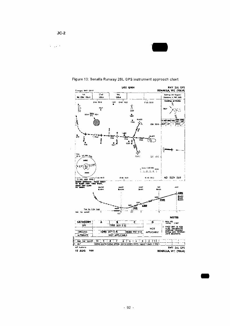
- 92 -
JC-2

- 93 -
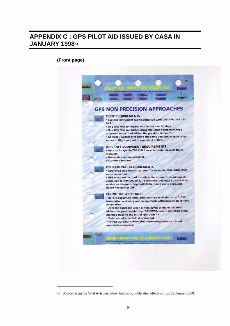
APPENDIX C : GPS PILOT AID ISSUED BY CASA IN JANUARY 199843
(Front page)
43 Sourced from the Civil Aviation Safety Authority, publication effective from 29 January 1998.
- 94 -

(Back page)
- 95 -

- 96 -
APPENDIX D : SOURCES AND SUBMISSIONS
Sources of information The sources of information provided during the re-opened investigation included:
• Aviation industry personnel including professional aircrew and maintenance engineers and avionics technicians
• Bureau of Meteorology
• Civil Aviation Safety Authority (Australia)
• FreeFlight Systems (USA)
• Prof. Brian O’Keeffe AO Hon LLD(Monash), BE (Qld), FIE Aust, FAIN
• State Coroner’s Office of Victoria
References Bainbridge L 1999, Processes underlying human performance. In DJ Garland, JA Wise, & VD Hopkin (Eds.), Handbook of aviation human factors. Mahwah, NJ: Lawrence Erlbaum, pp. 107-172.
Airservices Australia 2004 Manual of Air Traffic Services (MATS) Sec. 2 8.7, Revision dated 10 June 2004.
Airservices Australia 2004 Aeronautical Information Publication Australia (AIP) Sec. En Route 19.10 GPS- Operations Without RAIM, Revision dated June 2004.
FreeFlight Systems (Trimble) 1998 TNL 2101 I/O Approach Plus Receiver - Pilot Guide Revision dated 27 April 1998
Submissions Under Part 4, Division 2 (Investigation Reports), Section 26 of the Transport Safety Investigation Act 2003, the Executive Director may provide a draft report, on a confidential basis, to any person whom the Executive Director considers appropriate. Section 26 (1) (a) of the Act allows a person receiving a draft report to make submissions to the Executive Director about the draft report.
A draft of the relevant sections of this report was provided to:
• FreeFlight Systems (USA),
• National Transportation Safety Board (USA),
Submissions were received from:
• FreeFlight Systems (USA)
The submissions were reviewed and where considered appropriate, the text of the report was amended accordingly.