controller installation manual - motion … control engineering, inc. 11354 white rock road rancho...
TRANSCRIPT

MOTION CONTROL ENGINEERING, INC.11354 WHITE ROCK ROAD
RANCHO CORDOVA, CA 95742TELEPHONE (916)463-9200 FAX (916)463-9201
CONTROLLER INSTALLATION MANUAL
VVMC-1000 Series Turbo DFwith Sweo SCR Drive
Revision F.1February 1999
Part #: 42-02-7001 Rev. F.1

February 26, 1999 ADDENDUM 1
ADDENDUM MC-MP-1ES STATUS AND ERROR MESSAGES
The following Tables list all the status and error messages available for display on the MC-MP-1ES.Some of these messages apply only to specific types of controllers and may not appear onthis controller. For more information on the MC-MP-1ES status and error messages see theHUMAN INTERFACE and/or the TROUBLESHOOTING section(s) of this manual.
0.1 DIAGNOSTIC INDICATORS
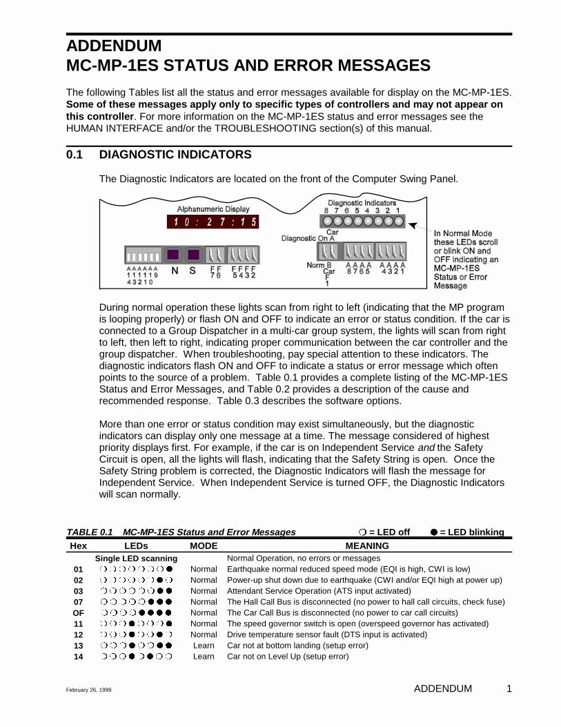
The Diagnostic Indicators are located on the front of the Computer Swing Panel.
During normal operation these lights scan from right to left (indicating that the MP programis looping properly) or flash ON and OFF to indicate an error or status condition. If the car isconnected to a Group Dispatcher in a multi-car group system, the lights will scan from rightto left, then left to right, indicating proper communication between the car controller and thegroup dispatcher. When troubleshooting, pay special attention to these indicators. Thediagnostic indicators flash ON and OFF to indicate a status or error message which oftenpoints to the source of a problem. Table 0.1 provides a complete listing of the MC-MP-1ESStatus and Error Messages, and Table 0.2 provides a description of the cause andrecommended response. Table 0.3 describes the software options.
More than one error or status condition may exist simultaneously, but the diagnosticindicators can display only one message at a time. The message considered of highestpriority displays first. For example, if the car is on Independent Service and the SafetyCircuit is open, all the lights will flash, indicating that the Safety String is open. Once theSafety String problem is corrected, the Diagnostic Indicators will flash the message forIndependent Service. When Independent Service is turned OFF, the Diagnostic Indicatorswill scan normally.
TABLE 0.1 MC-MP-1ES Status and Error Messages rr = LED off qq = LED blinkingHex LEDs MODE MEANING
Single LED scanning Normal Operation, no errors or messages01 r r r r r r r q Normal Earthquake normal reduced speed mode (EQI is high, CWI is low)02 r r r r r r q r Normal Power-up shut down due to earthquake (CWI and/or EQI high at power up)03 r r r r r r q q Normal Attendant Service Operation (ATS input activated)07 r r r r r q q q Normal The Hall Call Bus is disconnected (no power to hall call circuits, check fuse)OF r r r r q q q q Normal The Car Call Bus is disconnected (no power to car call circuits)11 r r r q r r r q Normal The speed governor switch is open (overspeed governor has activated)12 r r r q r r q r Normal Drive temperature sensor fault (DTS input is activated)13 r r r q r r q q Learn Car not at bottom landing (setup error)14 r r r q r q r r Learn Car not on Level Up (setup error)
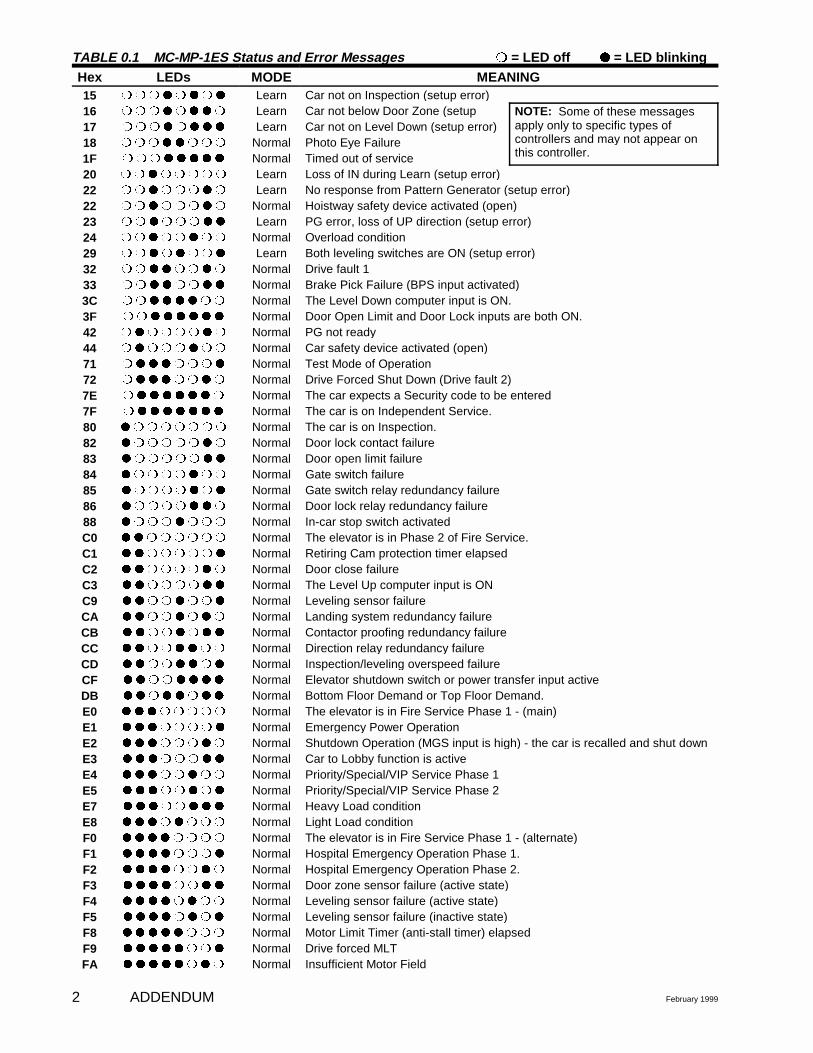
TABLE 0.1 MC-MP-1ES Status and Error Messages rr = LED off qq = LED blinkingHex LEDs MODE MEANING
ADDENDUM February 19992
15 r r r q r q r q Learn Car not on Inspection (setup error)16 r r r q r q q r Learn Car not below Door Zone (setup NOTE: Some of these messages
apply only to specific types ofcontrollers and may not appear onthis controller.
17 r r r q r q q q Learn Car not on Level Down (setup error)18 r r r q q r r r Normal Photo Eye Failure1F r r r q q q q q Normal Timed out of service20 r r q r r r r r Learn Loss of IN during Learn (setup error)22 r r q r r r q r Learn No response from Pattern Generator (setup error)22 r r q r r r q r Normal Hoistway safety device activated (open)23 r r q r r r q q Learn PG error, loss of UP direction (setup error)24 r r q r r q r r Normal Overload condition 29 r r q r q r r q Learn Both leveling switches are ON (setup error)32 r r q q r r q r Normal Drive fault 133 r r q q r r q q Normal Brake Pick Failure (BPS input activated)3C r r q q q q r r Normal The Level Down computer input is ON.3F r r q q q q q q Normal Door Open Limit and Door Lock inputs are both ON.42 r q r r r r q r Normal PG not ready44 r q r r r q r r Normal Car safety device activated (open)71 r q q q r r r q Normal Test Mode of Operation72 r q q q r r q r Normal Drive Forced Shut Down (Drive fault 2)7E r q q q q q q r Normal The car expects a Security code to be entered7F r q q q q q q q Normal The car is on Independent Service.80 q r r r r r r r Normal The car is on Inspection.82 q r r r r r q r Normal Door lock contact failure 83 q r r r r r q q Normal Door open limit failure 84 q r r r r q r r Normal Gate switch failure 85 q r r r r q r q Normal Gate switch relay redundancy failure86 q r r r r q q r Normal Door lock relay redundancy failure 88 q r r r q r r r Normal In-car stop switch activatedC0 q q r r r r r r Normal The elevator is in Phase 2 of Fire Service.C1 q q r r r r r q Normal Retiring Cam protection timer elapsedC2 q q r r r r q r Normal Door close failureC3 q q r r r r q q Normal The Level Up computer input is ONC9 q q r r q r r q Normal Leveling sensor failure CA q q r r q r q r Normal Landing system redundancy failureCB q q r r q r q q Normal Contactor proofing redundancy failureCC q q r r q q r r Normal Direction relay redundancy failureCD q q r r q q r q Normal Inspection/leveling overspeed failure CF q q r r q q q q Normal Elevator shutdown switch or power transfer input activeDB q q r q q r q q Normal Bottom Floor Demand or Top Floor Demand.E0 q q q r r r r r Normal The elevator is in Fire Service Phase 1 - (main)E1 q q q r r r r q Normal Emergency Power OperationE2 q q q r r r q r Normal Shutdown Operation (MGS input is high) - the car is recalled and shut downE3 q q q r r r q q Normal Car to Lobby function is activeE4 q q q r r q r r Normal Priority/Special/VIP Service Phase 1E5 q q q r r q r q Normal Priority/Special/VIP Service Phase 2E7 q q q r r q q q Normal Heavy Load conditionE8 q q q r q r r r Normal Light Load conditionF0 q q q q r r r r Normal The elevator is in Fire Service Phase 1 - (alternate)F1 q q q q r r r q Normal Hospital Emergency Operation Phase 1.F2 q q q q r r q r Normal Hospital Emergency Operation Phase 2.F3 q q q q r r q q Normal Door zone sensor failure (active state)F4 q q q q r q r r Normal Leveling sensor failure (active state)F5 q q q q r q r q Normal Leveling sensor failure (inactive state)F8 q q q q q r r r Normal Motor Limit Timer (anti-stall timer) elapsedF9 q q q q q r r q Normal Drive forced MLTFA q q q q q r q r Normal Insufficient Motor Field
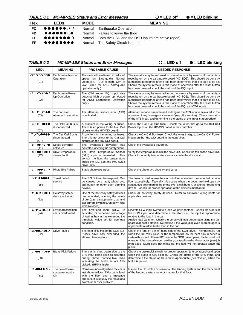
TABLE 0.1 MC-MP-1ES Status and Error Messages rr = LED off qq = LED blinkingHex LEDs MODE MEANING
February 26, 1999 ADDENDUM 3
FC q q q q q q r r Normal Earthquake OperationFD q q q q q q rq Normal Failure to leave the floorFE q q q q q q q r Normal Both the USD and the DSD inputs are active (open)FF q q q q q q q q Normal The Safety Circuit is open.
TABLE 0.2 MC-MP-1ES Status and Error Messages rr = LED off qq = LED blinking
LEDs MEANING PROBABLE CAUSE NEEDED RESPONSE
rrrrrrrq
(01)
Earthquake NormalOperation
The car is allowed to run at reducedspeed on Earthquake NormalOperation. (EQI is high, CWI islow; used for ANSI earthquakeoperation only.)
The elevator may be returned to normal service by means of momentaryreset button on the earthquake board (HC-EQ2). This should be done byauthorized personnel, after it has been determined that it is safe to do so.Should the system remain in this mode of operation after the reset buttonhas been pressed, check the status of the EQI input.
rrrrrrqr
(02)
Earthquake PowerUp Operation
The CWI and/or EQI input wasdetected high at power up. (Usedfor ANSI Earthquake Operationonly.)
The elevator may be returned to normal service by means of momentaryreset button on the earthquake board (HC-EQ2). This should be done byauthorized personnel, after it has been determined that it is safe to do so.Should the system remain in this mode of operation after the reset buttonhas been pressed, check the status of the EQI and CWI inputs.
rrrrrrqq
(03)The car is onAttendant operation
The attendant service input (ATS)is activated.
Attendant service is maintained as long as the ATS input is activated, in theabsence of any “emergency services” (e.g., fire service). Check the statusof the ATS input, and determine if the status of the input is appropriate.
rrrrrqqq
(07)
The Hall Call Bus isdisconnected
A problem in the wiring or fuses.There is no power to the Hall Callcircuits on the HC-CIO board.
Check the Hall Call Bus fuse. Check the wires that go to the Hall CallPower inputs on the HC-CIO board in the controller.
rrrrqqqq
(OF)
The Car Call Bus isdisconnected
A problem in the wiring or fuses.There is no power to the Car Callcircuits on the HC-CIO board.
Check the Car Call Bus fuse. Check the wires that go to the Car Call Powerinputs on the HC-CIO board in the controller.
rrrqrrrq
(11)Speed governoractivated
The overspeed governor hasactivated, opening the safety circuit.
Check the overspeed governor.
rrrqrrqr
(12)Drive temperaturesensor fault
The Drive Temperature Sensor(DTS) input is activated. Thissensor monitors the temperatureinside the IMC-S25 and IMC-G233drive units.
Verify the temperature inside the drive unit. Check the fan on the drive unit.Check for a faulty temperature sensor inside the drive unit.
rrrqqrrr
(18)Photo Eye Failure Stuck photo eye input. Check the photo eye circuitry and wires.
rrrqqqqq
(1F)
Timed out ofservice
The T.O.S. timer has expired. Canbe caused by a faulty photo eye,call button or other door openingdevice.
The timer is used to take the car out of service when the car is held at onefloor excessively. Typically this occurs when the doors are held open bycontinuous activation of the photo eye, a call button, or another reopeningdevice. Check for proper operation of the devices mentioned.
rrqrrrqr
(22)
Hoistway safetydevice activated
One of the hoistway safety deviceshas activated, opening the safetycircuit (e.g., pit stop switch, car andcwt buffers switches, up/down finallimit switches).
Check all hoistway safety devices. Refer to controller wiring prints forapplicable devices.
rrqrrqrr
(24)Overload condition,car is overloaded
The Overload input (OLW) isactivated, or perceived percentageof load in the car has exceeded thethreshold value set for overloadcondition.
Discrete OLW input (wired to a load weigher contact): Check the status ofthe OLW input, and determine if the status of the input is appropriaterelative to the load in the car.Analog load weigher: Check the perceived load percentage using the on-board diagnostic station. Determine if the value displayed (percentage) isappropriate relative to the load in the car.
rrqqrrqr
(32)Drive Fault 1 The heat sink inside the SCR (12-
Pulse) drive has exceeded theallowed temperature.
Check the fans on the left hand side of the SCR drive. They normally runwhen the RE relay picks or the temperature on the heat sink reaches acertain threshold. If fuse FD1 inside the SCR drive opens, the fans will notoperate. If the normally open auxiliary contact from the M-contactor (see jobprint page -SCR) does not make up, the fans will not operate when REpicks.
rrqqrrqq
(33)
Brake Pick Failure The car is shut down due to theBPS input being seen as activatedduring three consecutive runsindicating the brake is not fullypicked. (BPS is high)
Check the brake pick switch for proper operation (the contact should openwhen the brake is fully picked). Check the status of the BPS input, anddetermine if the status of the input is appropriate (deactivated) when thebrake is picked.
rrqqqqrr
(3C)
The Level Downcomputer input isON
Comes on normally when the car isjust above a floor. If the car is levelwith the floor and a messageappears, it is usually the result of aswitch or sensor problem.
Inspect the LD switch or sensor on the landing system and the placementof the landing system vane or magnet for that floor.
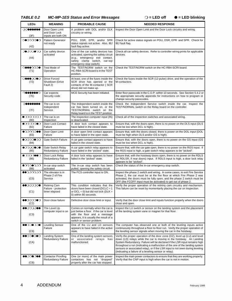
TABLE 0.2 MC-MP-1ES Status and Error Messages rr = LED off qq = LED blinking
LEDs MEANING PROBABLE CAUSE NEEDED RESPONSE
ADDENDUM February 19994
rrqqqqqq
(3F)
Door Open Limitand Door Lockinputs are both ON
A problem with DOL and/or DLKcircuitry or wiring.
Inspect the Door Open Limit and the Door Lock circuitry and wiring.
rqrrrrqr
(42)
Pattern Generatornot ready
PGU, DSR, EPR, and/or SPRstatus signals not active. Also, IBJfault flag active.
Check for active status signals on PGU, DSR, EPR and SPR. Check forIBJ fault flag.
rqrrrqrr
(44)
Car safety deviceactivated
One of the car safety devices hasactivated, opening the safety circuit(e.g., emergency exit contact,safety clamp switch, car-topemergency stop switch).
Check all car safety devices. Refer to controller wiring prints for applicabledevices.
rqqqrrrq
(71)Test Mode ofOperation
The TEST/NORM switch on theHC-RB4-SCRI board is in the TESTposition.
Check the TEST/NORM switch on the HC-RB4-SCRI board.
rqqqrrqr
(72)Drive ForcedShutdown (DriveFault 2)
At least, one of the fuses inside theSCR drive has opened or thecontacts of the M-contactor ( SCRdrive) did not make up.
Check the fuses inside the SCR (12-pulse) drive, and the operation of theM-contactors.
rqqqqqqr
(7E)Car expectsSecurity code
MCE Security has been initiated. Enter floor passcode in the C.O.P. within 10 seconds. See Section 5.4.2 orthe appropriate security appendix for instructions on how to program orchange security passcodes.
rqqqqqqq
(7F)
The car is onIndependentService
The Independent switch inside thecar has been turned on, or theTEST/NORMAL switch on theRelay board is in the TEST position.
Check the Independent Service switch inside the car. Inspect theTEST/NORMAL switch on the Relay board on the controller.
qrrrrrrr
(80)The car is onInspection
The inspection computer input (IN)is deactivated.
Check all of the inspection switches and associated wiring.
qrrrrrqr
(82)Door Lock ContactFailure
A door lock contact appears tohave failed in the closed state.
Ensure that, with the doors open, there is no power on the DLS input (DLSmust be low when DCL is high).
qrrrrrqq
(83)Door Open LimitFailure
A door open limit contact appearsto have failed in the open state.
Ensure that, with the doors closed, there is power on the DOL input (DOLmust be high when DLS and/or GS is high).
qrrrrqrr
(84)Gate Switch Failure A car gate contact appears to have
failed in the closed state. Ensure that, with the doors open, there is no power on the GS input (GSmust be low when DCL is high).
qrrrrqrq
(85)Gate Switch RelayRedundancy Failure
A car gate switch relay appears tohave failed in the “picked” state.
Ensure that, with the car gate open, there is no power on the RGS input. Ifthe RGS input is high, a gate switch relay appears to be “picked”.
qrrrrqqr
(86)Door Lock RelayRedundancy Failure
A door lock relay appears to havefailed in the “picked” state.
Ensure that, with the hoistway doors open, there is no power on the RDLS(or RDLSR, if rear doors) input. If RDLS input is high, a door lock relayappears to be “picked”.
qrrrqrrr
(88)In-car stop switchactivated
The in-car stop switch has beenpulled, opening the safety circuit.
Check the status of the in-car emergency stop switch.
qqrrrrrr
(C0)
The elevator is inPhase 2 of FireService
The FCS controller input is ON. Inspect the phase 2 switch and wiring. In some cases, to exit Fire ServicePhase 2, the car must be at the fire floor at which Fire Phase 2 wasactivated, the doors must be fully open, and the phase 2 switch must beOFF (the FCOFF input must be activated) to get out of phase 2.
qqrrrrrq
(C1)
Retiring CamFailure - protectiontimer elapsed
This condition indicates that thedoors have been closed (DCLC = 1or DCL = 0) but did not lock (DLK =0) within 80 seconds.
Verify the proper operation of the retiring cam circuitry and mechanism.This failure can be reset by momentarily placing the car on Inspection.
qqrrrrqr
(C2)Door close failure Defective door close limit or input. Verify that the door close limit and inputs function properly when the doors
close and open.
qqrrrrqq
(C3)
The Level Upcomputer input is on
Comes on normally when the car isjust below a floor. If the car is levelwith the floor and a messageappears, it is usually the result of aswitch or sensor problem.
Inspect the LU switch or sensor on the landing system and the placementof the landing system vane or magnet for that floor.
qqrrqrrq
(C9)
Leveling SensorFailure
One of the LU and LD sensorsappears to have failed in the activestate.
The computer has observed one or both of the leveling inputs activecontinuously throughout a floor-to-floor run. Verify the proper operation ofthe leveling sensor signals when moving the car in the hoistway.
qqrrqrqr
(CA)
Landing SystemRedundancy Failure
One of the landing system sensorsor associated re lays hasmalfunctioned.
Verify the proper operation of the door zone (DZ), level up (LU) and leveldown (LD) relays while the car is moving in the hoistway. An LandingSystem Redundancy Failure will be declared if the LSR input remains highthroughout a run (indicating a malfunction of the one of the landing systemsensors or associated relay), or if the LSR input is not seen during leveling(indicating a failure of a leveling sensor or relay).
qqrrqrqq
(CB)
Contactor ProofingRedundancy Failure
One (or more) of the main powercontactors has not “dropped”properly after the car has stopped.
Inspect the main power contactors to ensure that they are working properly.Verify that the CNP input is high when the car is not in motion.
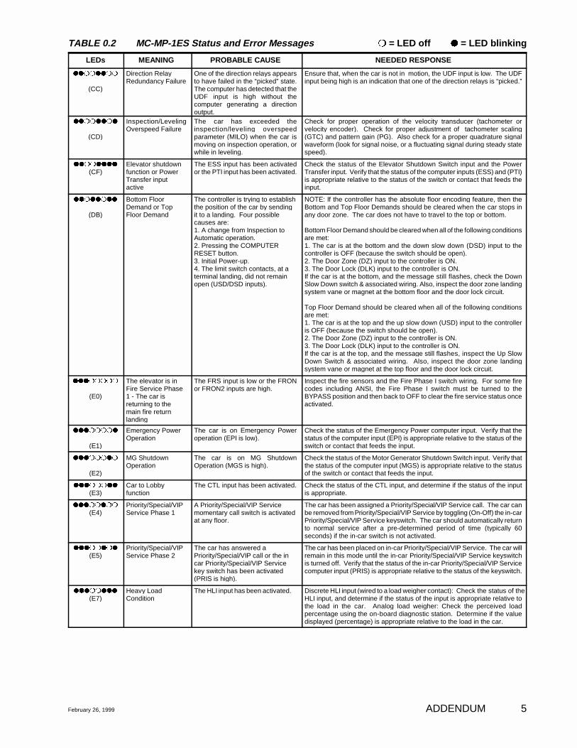
TABLE 0.2 MC-MP-1ES Status and Error Messages rr = LED off qq = LED blinking
LEDs MEANING PROBABLE CAUSE NEEDED RESPONSE
February 26, 1999 ADDENDUM 5
qqrrqqrr
(CC)
Direction RelayRedundancy Failure
One of the direction relays appearsto have failed in the “picked” state.The computer has detected that theUDF input is high without thecomputer generating a directionoutput.
Ensure that, when the car is not in motion, the UDF input is low. The UDFinput being high is an indication that one of the direction relays is “picked.”
qqrrqqrq
(CD)
Inspection/LevelingOverspeed Failure
The car has exceeded theinspection/leveling overspeedparameter (MILO) when the car ismoving on inspection operation, orwhile in leveling.
Check for proper operation of the velocity transducer (tachometer orvelocity encoder). Check for proper adjustment of tachometer scaling(GTC) and pattern gain (PG). Also check for a proper quadrature signalwaveform (look for signal noise, or a fluctuating signal during steady statespeed).
qqrrqqqq
(CF)Elevator shutdownfunction or PowerTransfer inputactive
The ESS input has been activatedor the PTI input has been activated.
Check the status of the Elevator Shutdown Switch input and the PowerTransfer input. Verify that the status of the computer inputs (ESS) and (PTI)is appropriate relative to the status of the switch or contact that feeds theinput.
qqrqqrqq
(DB)
Bottom FloorDemand or TopFloor Demand
The controller is trying to establishthe position of the car by sendingit to a landing. Four possiblecauses are:1. A change from Inspection toAutomatic operation.2. Pressing the COMPUTERRESET button.3. Initial Power-up.4. The limit switch contacts, at aterminal landing, did not remainopen (USD/DSD inputs).
NOTE: If the controller has the absolute floor encoding feature, then theBottom and Top Floor Demands should be cleared when the car stops inany door zone. The car does not have to travel to the top or bottom.
Bottom Floor Demand should be cleared when all of the following conditionsare met:1. The car is at the bottom and the down slow down (DSD) input to thecontroller is OFF (because the switch should be open).2. The Door Zone (DZ) input to the controller is ON.3. The Door Lock (DLK) input to the controller is ON.If the car is at the bottom, and the message still flashes, check the DownSlow Down switch & associated wiring. Also, inspect the door zone landingsystem vane or magnet at the bottom floor and the door lock circuit.
Top Floor Demand should be cleared when all of the following conditionsare met:1. The car is at the top and the up slow down (USD) input to the controlleris OFF (because the switch should be open).2. The Door Zone (DZ) input to the controller is ON.3. The Door Lock (DLK) input to the controller is ON.If the car is at the top, and the message still flashes, inspect the Up SlowDown Switch & associated wiring. Also, inspect the door zone landingsystem vane or magnet at the top floor and the door lock circuit.
qqqrrrrr
(E0)
The elevator is inFire Service Phase1 - The car isreturning to themain fire returnlanding
The FRS input is low or the FRONor FRON2 inputs are high.
Inspect the fire sensors and the Fire Phase I switch wiring. For some firecodes including ANSI, the Fire Phase I switch must be turned to theBYPASS position and then back to OFF to clear the fire service status onceactivated.
qqqrrrrq
(E1)
Emergency PowerOperation
The car is on Emergency Poweroperation (EPI is low).
Check the status of the Emergency Power computer input. Verify that thestatus of the computer input (EPI) is appropriate relative to the status of theswitch or contact that feeds the input.
qqqrrrqr
(E2)
MG ShutdownOperation
The car is on MG ShutdownOperation (MGS is high).
Check the status of the Motor Generator Shutdown Switch input. Verify thatthe status of the computer input (MGS) is appropriate relative to the statusof the switch or contact that feeds the input.
qqqrrrqq
(E3)Car to Lobbyfunction
The CTL input has been activated. Check the status of the CTL input, and determine if the status of the inputis appropriate.
qqqrrqrr
(E4)Priority/Special/VIPService Phase 1
A Priority/Special/VIP Servicemomentary call switch is activatedat any floor.
The car has been assigned a Priority/Special/VIP Service call. The car canbe removed from Priority/Special/VIP Service by toggling (On-Off) the in-carPriority/Special/VIP Service keyswitch. The car should automatically returnto normal service after a pre-determined period of time (typically 60seconds) if the in-car switch is not activated.
qqqrrqrq
(E5)Priority/Special/VIPService Phase 2
The car has answered aPriority/Special/VIP call or the incar Priority/Special/VIP Servicekey switch has been activated(PRIS is high).
The car has been placed on in-car Priority/Special/VIP Service. The car willremain in this mode until the in-car Priority/Special/VIP Service keyswitchis turned off. Verify that the status of the in-car Priority/Special/VIP Servicecomputer input (PRIS) is appropriate relative to the status of the keyswitch.
qqqrrqqq
(E7)Heavy LoadCondition
The HLI input has been activated. Discrete HLI input (wired to a load weigher contact): Check the status of theHLI input, and determine if the status of the input is appropriate relative tothe load in the car. Analog load weigher: Check the perceived loadpercentage using the on-board diagnostic station. Determine if the valuedisplayed (percentage) is appropriate relative to the load in the car.

TABLE 0.2 MC-MP-1ES Status and Error Messages rr = LED off qq = LED blinking
LEDs MEANING PROBABLE CAUSE NEEDED RESPONSE
ADDENDUM February 19996
qqqrqrrr
(E8)
Light LoadCondition
The Light Load Weighing input isactivated.
The Light Load error message is generated whenever the load inside thecar is less than the threshold specified to activate anti-nuisance operation,and car calls are registered. Response is only required if the anti-nuisancefunction (cancellation of car calls) appears to activate even when the car isloaded to a value above the threshold load value. Discrete (LLI) input (wired to a load weigher contact): check the status of the(LLI) input and determine if the status is appropriate relative to the load inthe car. Analog Load Weigher: check the perceived load percentage using the on-board diagnostic station. Determine if the value displayed (percentage) isappropriate relative to the load in the car.
qqqqrrrr
(F0)
The elevator is inFire Service Phase1 - The car isreturning to analternate fire returnlanding
The FRS input is low, the FRA inputis high or FRAON is active.
Inspect the fire sensors (especially the main floor sensor) and the FirePhase I switch wiring. For some fire codes including ANSI, the Fire PhaseI switch must be turned to the BYPASS position and then back to OFF toclear the fire service status once activated.
qqqqrrrq
(F1)
The car is onHospital EmergencyOperation Phase 1
A hospital emergency momentarycall switch is activated at any floor.
The car has been assigned a hospital emergency service call. The car canbe removed from Hospital Emergency Service by toggling (ON-OFF) the in-car Hospital Emergency Service keyswitch. The car should automaticallyreturn to normal service after a pre-determined period of time (typically 60seconds) if the in-car switch is not activated.
qqqqrrqr
(F2)
The car is onHospital EmergencyOperation Phase 2
The car has answered a hospitalemergency call or the in carhospital emergency key switch hasbeen activated (HOSP is high).
The car has been placed on in-car Hospital Emergency Service. The carwill remain in this mode until the in-car Hospital Emergency Servicekeyswitch is turned off. Verify that the status of the in-car hospital switchcomputer input (HOSP) is appropriate relative to the status of the keyswitch.
qqqqrrqq
(F3)Door zone sensorfailure (active state)
Probable causes may be: (1) a faulty door zone sensor orassociated circuitry (within thelanding system assembly); (2) faulty wiring from the landingsystem to the controller; (3) faulty computer input circuit(main relay board or HC-PI/Oboard).
Check the operation of the door zone sensors and associated wiring (placethe car on inspection, move the car away from the floor, noting thetransitions in the door zone signal(s) coming from the landing system).
Verify that the computer diagnostic display of DZ (or DZ rear) matches thestate of the sensor signals at the main relay board (or rear door relayboard).
qqqqrqrr
(F4)Leveling sensorfailure (active state)
Probable causes may be: (1) a faulty leveling sensor orassociated circuitry (within thelanding system assembly); (2) faulty wiring from the landingsystem to the controller; (3) faulty computer input circuit(main relay board or HC-PI/Oboard).
Check operation of the leveling sensors and associated wiring (place car oninspection, move above and below a landing, noting the transitions in theleveling signal(s) coming from the landing system).
Verify that the computer diagnostic display of LU and LD matches the stateof the sensor signals at the main relay board.
Check also the operation of any contacts that may be placed at the “lowside” (the “1-bus” side) of the LU and LD relay coils (e.g., H, INT). Checkthat such contacts close properly when appropriate.
qqqqrqrq
(F5)
Leveling sensorfailure (inactive state)
Probable causes may be: (1) a faulty leveling sensor orassociated circuitry (within thelanding system assembly); (2) faulty wiring from the landingsystem to the controller; (3) faulty computer input circuit(main relay board or HC-PI/Oboard).
Check operation of the leveling sensors and associated wiring (place car oninspection, move above and below a landing, noting the transitions in theleveling signal(s) coming from the landing system).
Verify that the computer diagnostic display of LU and LD matches the stateof the sensor signals at the main relay board.
qqqqqrrr
(F8)
Motor Limit Timer(anti-stall timer)elapsed
The Starter Overload or theThermal Overload has tripped, orthere is a mechanical problem thatprevents or slows the motion of thecar.
To clear the condition, the car must be put on inspection, then back intonormal operation, or the RESET button must be pressed. Immediatelycheck the Starter & Thermal Overloads and all circuitry associated with themotor.
qqqqqrrq
(F9)
Drive forced MLT The system is shut down due toexcessive number (4) of driverelated faults within 7 normal runs.
Check the special event calendar (F7 Screen) of this car to identify the driverelated faults.
qqqqqrqr
(FA)Insufficient MotorField
The Motor Field voltage is notproperly calibrated.
Check the Motor Field calibration (OCMF).
qqqqqqrr
(FC)
EarthquakeOperation
The car is shutdown on EarthquakeOperation (EQI is high; used forANSI and California EarthquakeOperation.)
The elevator may be returned to normal service by means of momentaryreset button on the earthquake board (HC-EQ2). This should be done byauthorized personnel, after it has been determined that it is safe to do so.Should the system remain in this mode of operation after the reset buttonhas been pressed, check the status of the EQI input.
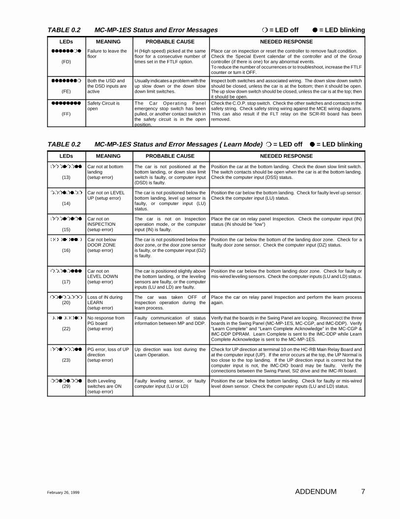
TABLE 0.2 MC-MP-1ES Status and Error Messages rr = LED off qq = LED blinking
LEDs MEANING PROBABLE CAUSE NEEDED RESPONSE
February 26, 1999 ADDENDUM 7
qqqqqqrq
(FD)
Failure to leave thefloor
H (High speed) picked at the samefloor for a consecutive number oftimes set in the FTLF option.
Place car on inspection or reset the controller to remove fault condition.Check the Special Event calendar of the controller and of the Groupcontroller (if there is one) for any abnormal events. To reduce the number of occurrences or to troubleshoot, increase the FTLFcounter or turn it OFF.
qqqqqqqr
(FE)
Both the USD andthe DSD inputs areactive
Usually indicates a problem with theup slow down or the down slowdown limit switches.
Inspect both switches and associated wiring. The down slow down switchshould be closed, unless the car is at the bottom; then it should be open.The up slow down switch should be closed, unless the car is at the top; thenit should be open.
qqqqqqqq
(FF)
Safety Circuit isopen
The Car Operating Panelemergency stop switch has beenpulled, or another contact switch inthe safety circuit is in the openposition.
Check the C.O.P. stop switch. Check the other switches and contacts in thesafety string. Check safety string wiring against the MCE wiring diagrams.This can also result if the FLT relay on the SCR-RI board has beenremoved.
TABLE 0.2 MC-MP-1ES Status and Error Messages ( Learn Mode) rr = LED off qq = LED blinking
LEDs MEANING PROBABLE CAUSE NEEDED RESPONSE
rrrqrrqq
(13)
Car not at bottomlanding(setup error)
The car is not positioned at thebottom landing, or down slow limitswitch is faulty, or computer input(DSD) is faulty.
Position the car at the bottom landing. Check the down slow limit switch.The switch contacts should be open when the car is at the bottom landing.Check the computer input (DSS) status.
rrrqrqrr
(14)
Car not on LEVELUP (setup error)
The car is not positioned below thebottom landing, level up sensor isfaulty, or computer input (LU)status.
Position the car below the bottom landing. Check for faulty level up sensor.Check the computer input (LU) status.
rrrqrqrq
(15)
Car not onINSPECTION (setup error)
The car is not on Inspectionoperation mode, or the computerinput (IN) is faulty.
Place the car on relay panel Inspection. Check the computer input (IN)status (IN should be “low”)
rrrqrqqr
(16)
Car not belowDOOR ZONE(setup error)
The car is not positioned below thedoor zone, or the door zone sensoris faulty, or the computer input (DZ)is faulty.
Position the car below the bottom of the landing door zone. Check for afaulty door zone sensor. Check the computer input (DZ) status.
rrrqrqqq
(17)
Car not on LEVEL DOWN(setup error)
The car is positioned slightly abovethe bottom landing, or the levelingsensors are faulty, or the computerinputs (LU and LD) are faulty.
Position the car below the bottom landing door zone. Check for faulty ormis-wired leveling sensors. Check the computer inputs (LU and LD) status.
rrqrrrrr
(20)Loss of IN duringLEARN (setup error)
The car was taken OFF ofInspection operation during thelearn process.
Place the car on relay panel Inspection and perform the learn processagain.
rrqrrrqr
(22)
No response fromPG board(setup error)
Faulty communication of statusinformation between MP and DDP.
Verify that the boards in the Swing Panel are looping. Reconnect the threeboards in the Swing Panel (MC-MP-1ES, MC-CGP, and IMC-DDP). Verify“Learn Complete” and “Learn Complete Acknowledge” in the MC-CGP &IMC-DDP DPRAM. Learn Complete is sent to the IMC-DDP while LearnComplete Acknowledge is sent to the MC-MP-1ES.
rrqrrrqq
(23)
PG error, loss of UPdirection(setup error)
Up direction was lost during theLearn Operation.
Check for UP direction at terminal 10 on the HC-RB Main Relay Board andat the computer input (UP). If the error occurs at the top, the UP Normal istoo close to the top landing. If the UP direction input is correct but thecomputer input is not, the IMC-DIO board may be faulty. Verify theconnections between the Swing Panel, SI2 drive and the IMC-RI board.
rrqrqrrq
(29)Both Levelingswitches are ON(setup error)
Faulty leveling sensor, or faultycomputer input (LU or LD)
Position the car below the bottom landing. Check for faulty or mis-wiredlevel down sensor. Check the computer inputs (LU and LD) status.
ADDENDUM February 19998
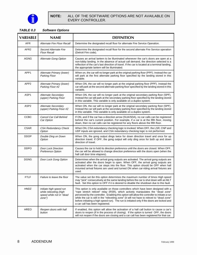
TABLE 0.3 Software Options
�������� ��� ������� �
AFR Alternate Fire Floor Recall Determine the designated recall floor for alternate Fire Service Operation.
AFR2 Second Alternate FireFloor Recall
Determine the designated recall floor for the second alternate Fire Service operation(Detroit Fire code).
AGNG Alternate Gong Option Causes an arrival lantern to be illuminated whenever the car's doors are open at anon-lobby landing. In the absence of actual call demand, the direction selected is areflection of the car's last direction of travel. If the car is located at a terminal landing,the appropriate lantern will be illuminated.
APP1 Alternate Primary (lower)Parking Floor
When on, the car will no longer park at the original parking floor (PPF). Instead the carwill park at the first alternate parking floor specified by the landing stored in thisvariable.
APP2 Alternate Primary (lower)Parking Floor #2
When ON, the car will no longer park at the original parking floor (PPF). Instead thecar will park at the second alternate parking floor specified by the landing stored in thisvariable.
ASP1 Alternate Secondary(upper) Parking Floor
When ON, the car will no longer park at the original secondary parking floor (SPF).Instead the car will park at the secondary parking floor specified by the landing storedin this variable. This variable is only available on a duplex system.
ASP2 Alternate Secondary(upper) Parking Floor #2
When ON, the car will no longer park at the original secondary parking floor (SPF).Instead the car will park at the secondary parking floor specified by the landing storedin this variable. This variable is only available on a duplex system.
CCBC Cancel Car Call BehindCar Option
If ON, and if the car has a direction arrow (SUA/SDA), no car calls can be registeredbehind the car's current position. For example, if a car is at the fifth floor, movingdown, then no car calls can be registered for any floors above the fifth floor.
CSAR CSA Redundancy CheckOption
When ON, CSA redundancy checking logic is invoked. When OFF, the LSR, CNP andUDF inputs are ignored, and CSA redundancy checking logic is not performed.
DDOP Double Ding on DownOption
When ON, the gong output dings twice for down direction travel and once for updirection travel. If OFF, the gong output will only ding once for both up and downdirection of travel.
DDPO Door Lock DirectionPreference Option
Causes the car to hold its direction preference until the doors are closed. When OFF,the car will be allowed to change direction preference with the doors open (when thehall call door time elapses).
DGNG Door Lock Gong Option Determines when the arrival gong outputs are activated. The arrival gong outputs areactivated after the doors begin to open. When OFF, the arrival gong outputs areactivated when the car steps into the floor. This option should be OFF when hallmounted arrival fixtures are used and turned ON when car-riding arrival fixtures areused.
FTLF Failure to leave the floor The value set ibn this option determines the maximum number of times High speedmay "pick" consecutively at the same landing before the car is shut down with an MLTfault. Set this option to OFF if it is desired to disable the shutdown due to this fault.
HNDZ Initiate high speed runwhile releveling (highspeed while not in “deadzone”)
This option is only available on those controllers which have been designed with a“rope stretch relevel” relay (RSR), which actively manipulates the “dead zone”perceived by the controller. Enabling this option will allow the controller to initiate a runwhile the car is still in the “releveling zone” (it will not have to relevel to “dead zone”before initiating a high speed run). The run is initiated only if the doors are locked anda car call has been registered.
HREO Reopen doors with hallbutton
If enabled, this option will allow the activation of a hall call button to cause a car’sdoors to reopen (if in the process of closing). If the option is turned OFF, the doorswill not reopen if the doors are closing and a car call has been registered for that car.
NOTE: ALL OF THE SOFTWARE OPTIONS ARE NOT AVAILABLE ONEVERY CONTROLLER.
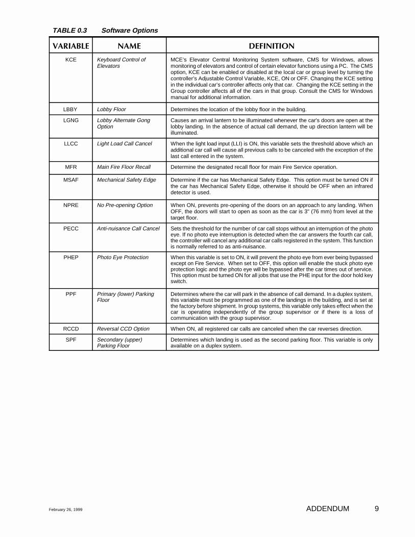
TABLE 0.3 Software Options
�������� ��� ������� �
February 26, 1999 ADDENDUM 9
KCE Keyboard Control ofElevators
MCE’s Elevator Central Monitoring System software, CMS for Windows, allowsmonitoring of elevators and control of certain elevator functions using a PC. The CMSoption, KCE can be enabled or disabled at the local car or group level by turning thecontroller’s Adjustable Control Variable, KCE, ON or OFF. Changing the KCE settingin the individual car’s controller affects only that car. Changing the KCE setting in theGroup controller affects all of the cars in that group. Consult the CMS for Windowsmanual for additional information.
LBBY Lobby Floor Determines the location of the lobby floor in the building.
LGNG Lobby Alternate GongOption
Causes an arrival lantern to be illuminated whenever the car's doors are open at thelobby landing. In the absence of actual call demand, the up direction lantern will beilluminated.
LLCC Light Load Call Cancel When the light load input (LLI) is ON, this variable sets the threshold above which anadditional car call will cause all previous calls to be canceled with the exception of thelast call entered in the system.
MFR Main Fire Floor Recall Determine the designated recall floor for main Fire Service operation.
MSAF Mechanical Safety Edge Determine if the car has Mechanical Safety Edge. This option must be turned ON ifthe car has Mechanical Safety Edge, otherwise it should be OFF when an infrareddetector is used.
NPRE No Pre-opening Option When ON, prevents pre-opening of the doors on an approach to any landing. WhenOFF, the doors will start to open as soon as the car is 3" (76 mm) from level at thetarget floor.
PECC Anti-nuisance Call Cancel Sets the threshold for the number of car call stops without an interruption of the photoeye. If no photo eye interruption is detected when the car answers the fourth car call,the controller will cancel any additional car calls registered in the system. This functionis normally referred to as anti-nuisance.
PHEP Photo Eye Protection When this variable is set to ON, it will prevent the photo eye from ever being bypassedexcept on Fire Service. When set to OFF, this option will enable the stuck photo eyeprotection logic and the photo eye will be bypassed after the car times out of service.This option must be turned ON for all jobs that use the PHE input for the door hold keyswitch.
PPF Primary (lower) ParkingFloor
Determines where the car will park in the absence of call demand. In a duplex system,this variable must be programmed as one of the landings in the building, and is set atthe factory before shipment. In group systems, this variable only takes effect when thecar is operating independently of the group supervisor or if there is a loss ofcommunication with the group supervisor.
RCCD Reversal CCD Option When ON, all registered car calls are canceled when the car reverses direction.
SPF Secondary (upper)Parking Floor
Determines which landing is used as the second parking floor. This variable is onlyavailable on a duplex system.

TABLE OF CONTENTS
Important Precautions and Notes . . . . . . . . . . . . . . . . . . . . . . . . . . . . . . . . . . . . . . . . i-i
Limited Warranty . . . . . . . . . . . . . . . . . . . . . . . . . . . . . . . . . . . . . . . . . . . . . . . . . . . i-iii
SECTION 1
GENERAL PRODUCT DESCRIPTION
1.0 General Information . . . . . . . . . . . . . . . . . . . . . . . . . . . . . . . . . . . . . . . . . . . . . 1-1
1.0.1 Equipment Categories . . . . . . . . . . . . . . . . . . . . . . . . . . . . . . . . . . . . 1-1
1.1 Car Control General Description . . . . . . . . . . . . . . . . . . . . . . . . . . . . . . . . . . 1-2
1.1.1 Car Operation Control (COC) . . . . . . . . . . . . . . . . . . . . . . . . . . . . . . 1-21.1.2 Car Communication Control (CCC) . . . . . . . . . . . . . . . . . . . . . . . . . 1-21.1.3 Car Motion Control (CMC) . . . . . . . . . . . . . . . . . . . . . . . . . . . . . . . . 1-21.1.4 Car Power Control (CPC) . . . . . . . . . . . . . . . . . . . . . . . . . . . . . . . . . 1-31.1.5 Physical Layout of Car Controller . . . . . . . . . . . . . . . . . . . . . . . . . . . 1-31.1.6 Functional Description . . . . . . . . . . . . . . . . . . . . . . . . . . . . . . . . . . . . 1-4
1.2 Landing System Control Box (LS-QUAD-2 or LS-QUAD-2R) . . . . . . . . . . . 1-8
1.3 Human Interface Tools and Peripherals . . . . . . . . . . . . . . . . . . . . . . . . . . . . . . 1-9
1.4 Group Dispatcher (two or more cars) . . . . . . . . . . . . . . . . . . . . . . . . . . . . . . . 1-9
SECTION 2
INSTALLATION OF VVMC-1000 SERIESTURBO DF SCR CONTROLLER
2.0 General Information . . . . . . . . . . . . . . . . . . . . . . . . . . . . . . . . . . . . . . . . . . . . . 2-1
2.1 Site Selection . . . . . . . . . . . . . . . . . . . . . . . . . . . . . . . . . . . . . . . . . . . . . . . . . . 2-1
2.2 Environmental Considerations . . . . . . . . . . . . . . . . . . . . . . . . . . . . . . . . . . . . . 2-2
Table of Contents
2.3 Recommended Tools and Test Equipment . . . . . . . . . . . . . . . . . . . . . . . . . . . 2-2
2.4 Installation, Wiring Guidelines and Instructions . . . . . . . . . . . . . . . . . . . . . . . 2-2
2.4.1 The Wiring Prints . . . . . . . . . . . . . . . . . . . . . . . . . . . . . . . . . . . . . . . . 2-32.4.2 Ground Wiring . . . . . . . . . . . . . . . . . . . . . . . . . . . . . . . . . . . . . . . . . . 2-42.4.3 Hoistway Control Equipment
Installation and Wiring . . . . . . . . . . . . . . . . . . . . . . . . . . . . . . . . . . . . 2-4
2.4.3.1 Installation of Perforated Steel Tape . . . . . . . . . . . . . . . . . 2-42.4.3.2 Installation of Hoistway Limit Switches . . . . . . . . . . . . . . 2-52.4.3.3 Installation and Wiring of Hoistway
Terminal Strips and Traveling Cables . . . . . . . . . . . . . . . . 2-5
2.4.4 Elevator Car Control EquipmentInstallation and Wiring . . . . . . . . . . . . . . . . . . . . . . . . . . . . . . . . . . . . 2-5
2.4.4.1 Installation of Landing System Control Box (LS-QUAD-2 or LS-QUAD-2R) . . . . . . . . . . . . . . . . . . . . 2-5
2.4.4.2 Installation of MagneticStrips on the Steel Tape . . . . . . . . . . . . . . . . . . . . . . . . . . . 2-7
2.4.4.3 TM Switch Wiring and Adjustment (if used) . . . . . . . . . . . 2-82.4.4.4 Door Operator Diode Installation (if used) . . . . . . . . . . . . 2-8
2.4.5 Machine Room Control EquipmentInstallation and Wiring . . . . . . . . . . . . . . . . . . . . . . . . . . . . . . . . . . . . 2-8
2.4.5.1 Controller Installation . . . . . . . . . . . . . . . . . . . . . . . . . . . . . 2-82.4.5.2 Controller Wiring . . . . . . . . . . . . . . . . . . . . . . . . . . . . . . . . 2-82.4.5.3 DC Hoist Motor Wiring . . . . . . . . . . . . . . . . . . . . . . . . . . 2-102.4.5.4 Isolation Transformer Wiring . . . . . . . . . . . . . . . . . . . . . . 2-102.4.5.5 Tachometer Installation and Wiring . . . . . . . . . . . . . . . . . 2-10
SECTION 3
START UP SEQUENCE FOR MCE'S VVMC-1000 SERIES TURBODF WITH SWEO SCR DRIVE
3.0 General Information . . . . . . . . . . . . . . . . . . . . . . . . . . . . . . . . . . . . . . . . . . . . . 3-1
Table of Contents
3.1 Ground Check . . . . . . . . . . . . . . . . . . . . . . . . . . . . . . . . . . . . . . . . . . . . . . . . . 3-2
3.2 SCR Drive Information . . . . . . . . . . . . . . . . . . . . . . . . . . . . . . . . . . . . . . . . . . 3-2
3.3 Before Turning On the Power . . . . . . . . . . . . . . . . . . . . . . . . . . . . . . . . . . . . . 3-3
3.3.1 Initial Drive Adjustments . . . . . . . . . . . . . . . . . . . . . . . . . . . . . . . . . . 3-43.3.2 Initial IMC-GIO Board Adjustments . . . . . . . . . . . . . . . . . . . . . . . . . 3-5
3.4 Power Application . . . . . . . . . . . . . . . . . . . . . . . . . . . . . . . . . . . . . . . . . . . . . . 3-6
3.4.1 Drive Start Up . . . . . . . . . . . . . . . . . . . . . . . . . . . . . . . . . . . . . . . . . . 3-73.4.2 Operating Sequence on Inspection Operation . . . . . . . . . . . . . . . . . . 3-83.4.3 Running on Inspection Operation . . . . . . . . . . . . . . . . . . . . . . . . . . . 3-93.4.4 Preparing the Elevator to Run
on Automatic Operation . . . . . . . . . . . . . . . . . . . . . . . . . . . . . . . . . . 3-10
3.4.4.1 Test Equipment Required . . . . . . . . . . . . . . . . . . . . . . . . . 3-103.4.4.2 Initial Speed Calibration . . . . . . . . . . . . . . . . . . . . . . . . . . 3-103.4.4.3 Mechanical Checks . . . . . . . . . . . . . . . . . . . . . . . . . . . . . . 3-113.4.4.4 Electrical Checks . . . . . . . . . . . . . . . . . . . . . . . . . . . . . . . 3-11
3.5 Preparation for Final Adjustment . . . . . . . . . . . . . . . . . . . . . . . . . . . . . . . . . . 3-12
3.6 VVC-2-G Drive Unit Adjustments . . . . . . . . . . . . . . . . . . . . . . . . . . . . . . . . 3-15
3.7 Sweo SCR Drive Control Board Trimpots . . . . . . . . . . . . . . . . . . . . . . . . . . 3-19
3.8 Explanation of Trimpotson HC-SCR Board (SCR Drive Interface Board) . . . . . . . . . . . . . . . . . . . . . 3-21
3.9 Traction Panel Adjustments . . . . . . . . . . . . . . . . . . . . . . . . . . . . . . . . . . . . . . 3-21
SECTION 4
FINAL ADJUSTMENT FOR MCE'S VVMC-1000 SERIESTURBO DF WITH SWEO SCR DRIVE
4.0 General Information . . . . . . . . . . . . . . . . . . . . . . . . . . . . . . . . . . . . . . . . . . . . . 4-1
Table of Contents
4.1 Set Up of CRT Terminal . . . . . . . . . . . . . . . . . . . . . . . . . . . . . . . . . . . . . . . . . 4-1
4.2 Running the Car on Inspectionunder Computer Control . . . . . . . . . . . . . . . . . . . . . . . . . . . . . . . . . . . . . . . . . 4-3
4.3 Hoistway Learn Operation . . . . . . . . . . . . . . . . . . . . . . . . . . . . . . . . . . . . . . . . 4-4
4.4 Verifying Absolute Floor Numbers . . . . . . . . . . . . . . . . . . . . . . . . . . . . . . . . . 4-7
4.5 Running on Automatic Operation . . . . . . . . . . . . . . . . . . . . . . . . . . . . . . . . . . 4-9
4.5.1 Reaching Contract Speed . . . . . . . . . . . . . . . . . . . . . . . . . . . . . . . . . 4-114.5.2 Changing Standing Motor Field and Brake Voltage
from the Drive Units . . . . . . . . . . . . . . . . . . . . . . . . . . . . . . . . . . . . 4-134.5.3 Explanation of Velocity Profile Parameters . . . . . . . . . . . . . . . . . . . 4-144.5.4 Shaping the Velocity Profile . . . . . . . . . . . . . . . . . . . . . . . . . . . . . . 4-154.5.5 Adjusting Leveling and Final Stop . . . . . . . . . . . . . . . . . . . . . . . . . 4-174.5.6 Calibration of Safety Functions . . . . . . . . . . . . . . . . . . . . . . . . . . . . 4-194.5.7 Controlling Initial Start of Car Motion . . . . . . . . . . . . . . . . . . . . . . 4-23
4.5.7.1 Adjustment of Load Compensation . . . . . . . . . . . . . . . . . 4-24
4.5.7.1.1 Rationale . . . . . . . . . . . . . . . . . . . . . . . . . . . . . . 4-244.5.7.1.2 Hardware . . . . . . . . . . . . . . . . . . . . . . . . . . . . . . 4-24
4.5.7.1.2.1 HC-LWB Board . . . . . . . . . . . . . . . . . . . . 4-24 4.5.7.1.2.2 IMC-GIO Board . . . . . . . . . . . . . . . . . . . . 4-24
4.5.7.1.3 Installation . . . . . . . . . . . . . . . . . . . . . . . . . . . . . 4-244.5.7.1.4 PI Compensation . . . . . . . . . . . . . . . . . . . . . . . . 4-254.5.7.1.5 Adjustment . . . . . . . . . . . . . . . . . . . . . . . . . . . . 4-26
4.5.7.2 Adjustment of Brake Timing Circuitry . . . . . . . . . . . . . . 4-27
4.6 Learning Normal VelocityAssociated with Each Terminal Limit Switch . . . . . . . . . . . . . . . . . . . . . . . . 4-29
4.7 Procedures for Performingthe Final Acceptance Tests . . . . . . . . . . . . . . . . . . . . . . . . . . . . . . . . . . . . . . 4-32
4.7.1 Contract Speed Buffer Tests . . . . . . . . . . . . . . . . . . . . . . . . . . . . . . 4-324.7.2 Governor Tests . . . . . . . . . . . . . . . . . . . . . . . . . . . . . . . . . . . . . . . . . 4-33
Table of Contents
4.7.3 Inspection/Leveling 150 fpm Overspeed Test . . . . . . . . . . . . . . . . . 4-344.7.4 Emergency Terminal Speed Limiting Device Test . . . . . . . . . . . . . 4-344.7.5 Terminal Slowdown Limit Switches . . . . . . . . . . . . . . . . . . . . . . . . 4-34
SECTION 5
HUMAN INTERFACE
5.0 General Information . . . . . . . . . . . . . . . . . . . . . . . . . . . . . . . . . . . . . . . . . . . . . 5-1
5.1 CRT Terminal . . . . . . . . . . . . . . . . . . . . . . . . . . . . . . . . . . . . . . . . . . . . . . . . . 5-1
5.2 Enhanced On-Board Diagnostics (EOD) . . . . . . . . . . . . . . . . . . . . . . . . . . . . . 5-1
5.2.0 General Information . . . . . . . . . . . . . . . . . . . . . . . . . . . . . . . . . . . . . . 5-15.2.1 Functional Description
of Indicators and Switches of EOD . . . . . . . . . . . . . . . . . . . . . . . . . . 5-25.2.2 Normal Mode of Operation . . . . . . . . . . . . . . . . . . . . . . . . . . . . . . . . 5-5
5.2.2.1 Adjustment of the Elevator Timers . . . . . . . . . . . . . . . . . . 5-55.2.2.2 Adjustment of Real Time Clock . . . . . . . . . . . . . . . . . . . . . 5-65.2.2.3 Viewing the Internal Flags . . . . . . . . . . . . . . . . . . . . . . . . . 5-7
5.2.3 Diagnostic Mode of Operation . . . . . . . . . . . . . . . . . . . . . . . . . . . . . . 5-7
5.2.3.1 Viewing the MC-MPand IMC-DDP Computer Memory Flags . . . . . . . . . . . . . . 5-7
5.2.3.2 Viewing and Entering Calls . . . . . . . . . . . . . . . . . . . . . . . . 5-8
5.2.4 System Mode of Operation . . . . . . . . . . . . . . . . . . . . . . . . . . . . . . . . 5-9
5.2.4.1 Viewing and Changingthe Security Codes . . . . . . . . . . . . . . . . . . . . . . . . . . . . . . . 5-9
5.2.4.2 System Learn Operation . . . . . . . . . . . . . . . . . . . . . . . . . . 5-11
5.3 IMC-GIO On-Board Diagnostics . . . . . . . . . . . . . . . . . . . . . . . . . . . . . . . . . . 5-12
5.3.1 Functional Description of Indicators and Switches . . . . . . . . . . . . . 5-125.3.2 Startup Operation . . . . . . . . . . . . . . . . . . . . . . . . . . . . . . . . . . . . . . . 5-135.3.3 IMC-GIO Learn Operation . . . . . . . . . . . . . . . . . . . . . . . . . . . . . . . . 5-135.3.4 IMC-GIO Normal Operation . . . . . . . . . . . . . . . . . . . . . . . . . . . . . . 5-14

Table of Contents
SECTION 6
DESCRIPTION OF OPERATION AND TROUBLESHOOTINGGUIDE
6.0 General Information . . . . . . . . . . . . . . . . . . . . . . . . . . . . . . . . . . . . . . . . . . . . . 6-1
6.1 Tracing Signals in the Controller . . . . . . . . . . . . . . . . . . . . . . . . . . . . . . . . . . . 6-1
6.2 Door Logic . . . . . . . . . . . . . . . . . . . . . . . . . . . . . . . . . . . . . . . . . . . . . . . . . . . . 6-3
6.3 Call Logic. . . . . . . . . . . . . . . . . . . . . . . . . . . . . . . . . . . . . . . . . . . . . . . . . . . . . 6-6
6.3.1 Normal Operation . . . . . . . . . . . . . . . . . . . . . . . . . . . . . . . . . . . . . . . 6-66.3.2 Preparation for Troubleshooting Call Circuits . . . . . . . . . . . . . . . . . . 6-76.3.3 Troubleshooting . . . . . . . . . . . . . . . . . . . . . . . . . . . . . . . . . . . . . . . . . 6-7
6.4 Pattern Generator Troubleshooting . . . . . . . . . . . . . . . . . . . . . . . . . . . . . . . . . 6-9
6.4.1 Using the CRT Terminal forTroubleshooting the Pattern Generator . . . . . . . . . . . . . . . . . . . . . . . 6-9
6.4.1.1 Elevator Graphic Display F3 Screen . . . . . . . . . . . . . . . . . 6-96.4.1.2 Velocity Profile F2 Screen . . . . . . . . . . . . . . . . . . . . . . . . 6-126.4.1.3 MCE Special Event Calendar
Entries Screen F7 . . . . . . . . . . . . . . . . . . . . . . . . . . . . . . . 6-126.4.1.4 List and Definitions of
Special Events Calendar Entries . . . . . . . . . . . . . . . . . . . . 6-126.4.1.5 Limits of Motion Parameters . . . . . . . . . . . . . . . . . . . . . . 6-15
6.5.2 Auto Reset Feature . . . . . . . . . . . . . . . . . . . . . . . . . . . . . . . . . . . . . . 6-16
SECTION 7
JOB PRINTS
Nomenclature . . . . . . . . . . . . . . . . . . . . . . . . . . . . . . . . . . . . . . . . . . . . . . . . . . . . . . 7-1
Table of Contents
Fire Module Function Diagram . . . . . . . . . . . . . . . . . . . . . . . . . . . . . . . . . . . . . . . . 7-2
APPENDIX
Appendix A Removing Circuit Boards from the Computer Swing Panel . . . . . . . . 8-1Appendix B Elevator Security Information and Operation . . . . . . . . . . . . . . . . . . . 8-2Appendix C Instructions for Changing EPROMs and Microcontrollers . . . . . . . . . 8-4Appendix D Instructions for the Inspection of Quadrature Position
Pulser on the LS-QUAD-2 . . . . . . . . . . . . . . . . . . . . . . . . . . . . . . . . . 8-8Appendix E Software Options . . . . . . . . . . . . . . . . . . . . . . . . . . . . . . . . . . . . . . . . 8-10
TABLES
Table 3.1 SCR Control Circuit Board Adjustments . . . . . . . . . . . . . . . . . . . . . . 3-5Table 3.2 VVC-2-G Drive Unit Trimpot Summary . . . . . . . . . . . . . . . . . . . . . 3-18Table 3.3 Sweo SCR Drive Trimpot Summary . . . . . . . . . . . . . . . . . . . . . . . . 3-20
Table 4.1 Absolute Floor Code Indicator Listing . . . . . . . . . . . . . . . . . . . . . . . . 4-8Table 4.2 Typical Recommended Speed Parameters . . . . . . . . . . . . . . . . . . . . 4-37Table 4.3 Range and Format of the
Pattern Generator Speed Parameters . . . . . . . . . . . . . . . . . . . . . . . . 4-38
Table 5.1 Changing Floor Security Statusand Security Codes . . . . . . . . . . . . . . . . . . . . . . . . . . . . . . . . . . . . . . 5-10
Table 5.2 EEPROM Error Conditions . . . . . . . . . . . . . . . . . . . . . . . . . . . . . . . 5-14Table 5.3 Flags for MC-MP Board . . . . . . . . . . . . . . . . . . . . . . . . . . . . . . . . . 5-15Table 5.4 Flags for IMC-DDP Board . . . . . . . . . . . . . . . . . . . . . . . . . . . . . . . . 5-17Table 5.5 Clock Flags and Their Ranges . . . . . . . . . . . . . . . . . . . . . . . . . . . . . 5-18Table 5.6 Timer Flags and Their Ranges . . . . . . . . . . . . . . . . . . . . . . . . . . . . . 5-18Table 5.7 MC-MP Board Status Displays . . . . . . . . . . . . . . . . . . . . . . . . . . . . 5-22Table 5.8 IMC-DDP Board Status Displays . . . . . . . . . . . . . . . . . . . . . . . . . . 5-23
Table E.1 Software Option Appendix . . . . . . . . . . . . . . . . . . . . . . . . . . . . . . . 8-10
FIGURES

Table of Contents
Figure 1.1 Car Controller Functional Layout . . . . . . . . . . . . . . . . . . . . . . . . . . 1-10Figure 1.2 Typical Physical Layout
VVMC-1000 Series Turbo DF SCR . . . . . . . . . . . . . . . . . . . . . . . . 1-11Figure 1.3 Computer Swing Panel . . . . . . . . . . . . . . . . . . . . . . . . . . . . . . . . . . 1-12Figure 1.4 Pattern Generator I/O Subsystem (IMC-GIO) . . . . . . . . . . . . . . . . . 1-13Figure 1.5 IMC-RB Relay Board Layout . . . . . . . . . . . . . . . . . . . . . . . . . . . . . 1-14Figure 1.6 HC-RB Relay Board Layout . . . . . . . . . . . . . . . . . . . . . . . . . . . . . 1-15Figure 1.7 LS-QUAD-2 Detail . . . . . . . . . . . . . . . . . . . . . . . . . . . . . . . . . . . . . 1-16
Figure 2.1 Position Pulser Shielded Cable Wiring . . . . . . . . . . . . . . . . . . . . . . . 2-6Figure 2.2 Tachometer Installation . . . . . . . . . . . . . . . . . . . . . . . . . . . . . . . . . . 2-11Figure 2.3 Controller Board Layout - Typical Example . . . . . . . . . . . . . . . . . . 2-12
Figure 3.1 VVC-2-G Drive Unit Adjustments . . . . . . . . . . . . . . . . . . . . . . . . . 3-15Figure 3.2 IMC-GIO Board Adjustments and Indicators . . . . . . . . . . . . . . . . . 3-22
Figure 4.1 Nyload Weighing System . . . . . . . . . . . . . . . . . . . . . . . . . . . . . . . . 4-25Figure 4.2 MC-MRS Link to CRT Terminal . . . . . . . . . . . . . . . . . . . . . . . . . . . 4-39Figure 4.3 Digital Drive Parameters F1 Screen . . . . . . . . . . . . . . . . . . . . . . . . . 4-40Figure 4.4 Elevator Graphic Display F3 Screen . . . . . . . . . . . . . . . . . . . . . . . . 4-41Figure 4.5 Typical Velocity Profile F2 Screen . . . . . . . . . . . . . . . . . . . . . . . . . 4-42Figure 4.6 LS-QUAD-2 Detail . . . . . . . . . . . . . . . . . . . . . . . . . . . . . . . . . . . . . 4-43
Figure 5.1 Computer Swing Panel Front View . . . . . . . . . . . . . . . . . . . . . . . . . 5-19Figure 5.2 Computer Swing Panel Top View . . . . . . . . . . . . . . . . . . . . . . . . . . 5-20Figure 5.3 Computer Swing Panel Backplate . . . . . . . . . . . . . . . . . . . . . . . . . . 5-21Figure 5.4 General Memory Variables or Flags for MC-MP Board . . . . . . . . . 5-24Figure 5.5 Rear Door Memory Variables or Flags for MC-MP Board . . . . . . . 5-25Figure 5.6 General Memory Variable Flags for IMC-DDP Pattern
Generator Computer . . . . . . . . . . . . . . . . . . . . . . . . . . . . . . . . . . . . . 5-26
Figure 6.1 HC-PI/O Input Output Details . . . . . . . . . . . . . . . . . . . . . . . . . . . . . 6-17Figure 6.2 HC-RB Relay Board Detail . . . . . . . . . . . . . . . . . . . . . . . . . . . . . . . 6-18Figure 6.3 HC-CI/O Call Board Details . . . . . . . . . . . . . . . . . . . . . . . . . . . . . . 6-19
Figure A-1 Computer Swing Panel with Boards, Top View . . . . . . . . . . . . . . . . 8-1Figure A-1 Computer Swing Panel Without Boards, Top View . . . . . . . . . . . . . 8-1Figure A-1 Computer Swing Panel Boards, Snapped Together . . . . . . . . . . . . . . 8-1Figure A-1 Computer Swing Panel with Boards, Unsnapped . . . . . . . . . . . . . . . 8-1
Figure C.1 EPROM Location on Main Processor Board (MC-MP) . . . . . . . . . . 8-6Figure C.2 EPROM on Communication Processor Board (MC-CP) . . . . . . . . . . 8-6
Table of Contents
Figure C.3 EPROM and EEPROM Location on Digital Drive Board (IMC-DDP) . . . . . . . . . . . . . . . . . . . . . . . . . . . . . . . . . . . . . . . 8-7
Figure C.4 IMC-GIO Board Layout . . . . . . . . . . . . . . . . . . . . . . . . . . . . . . . . . . . 8-7
Figure D.1 LS-QUAD Enclosure, Top View . . . . . . . . . . . . . . . . . . . . . . . . . . . . 8-8Figure D.2 Attaching SB1 to LS-QUAD-2 Backplate . . . . . . . . . . . . . . . . . . . . . 8-8Figure D.3 Signal Comparison of DP1 and DP2 . . . . . . . . . . . . . . . . . . . . . . . . . 8-9

i-i
IMPORTANT PRECAUTIONS AND NOTES
We strongly recommend that this manual be read carefully before proceeding withinstallation. Throughout this manual paragraphs are introduced by the words WARN-ING, CAUTION or NOTE. These words are defined below.
WARNING - Denotes operating procedures and practices which, if not done correctly,will probably result in personal injury or substantial damage toequipment.
CAUTION - Denotes operating procedures and practices which, if not observed, mayresult in some damage to equipment.
NOTE - Denotes procedures, practices or information which is intended to beimmediately helpful and informative.
The following general rules and safety precautions must be observed for safe and reliableoperation of this system.
WARNING
Elevator control products must be installed by experienced field personnel. This manualdoes not address code requirements. The field personnel must know all the rules andregulations pertaining to the safe installation and operation of elevators.
WARNING
This equipment is an O.E.M. product designed and built to comply with ANSI A17.1,National Electrical Code, CAN/CSA-B44.1-M91/ASME-A17.5-1991 and must beinstalled by a qualified contractor. It is the responsibility of the contractor to make surethat the final installation complies with all local codes and is installed in a safe manner.
WARNING
The three-phase AC power supply to this equipment must originate from a fuseddisconnect switch or circuit breaker which is sized in conformance with all applicablenational, state and local electrical codes, in order to provide the necessary overloadprotection for the drive unit and motor. Incorrect motor branch circuit protection willvoid warranty and may create a hazardous condition.
WARNING
Proper grounding is vitally important to the safe and successful operation of the system.Bring the ground wire to the system subplate. Choose the proper conductor size and

i-ii
minimize the resistance to ground by using the shortest possible routing. See NationalElectrical Code Article 250-95, or related local applicable code.
CAUTION
Do not connect the output triacs directly to a hot bus (2, 3 or 4 bus). This can damagethe triacs. PI'S, direction arrows and terminals 40 & 42 are examples of outputs that canbe damaged this way. Note: miswiring terminal 39 into 40 can damage the fire warningindicator triac.
NOTE
Environmental Considerations: Keep the machine room clean. Controllers aregenerally in NEMA 1 enclosures. Do not install the controller in a dusty area. Do notinstall the controller in a carpeted area. Keep room temperature between 0� F and 104�F. Avoid condensation on the equipment. Do not install the controller in a hazardouslocation and where excessive amounts of vapors or chemical fumes may be present.Make sure power line fluctuations are within + 10%.
NOTE
The controller may be shipped without the final running program. However this unitmay be installed, hooked up and run on inspection operation. Call MCE about a weekbefore turning the elevator over to full automatic operation so the running program canbe shipped.
If a program chip on a computer board needs to be changed, read the instructions andlearn how to install the new chip. Plugging in these devices backwards may damage thechip.
NOTE
The HC-PI/O and HC-CI/O boards are equipped with quick disconnect terminals.During the initial installation, it may be necessary to remove these terminal connectors.Hook up the field wires to these terminals and test for no shorts to ground (1 bus) and to2, 3 and 4 terminals before plugging these terminals back into the circuit boards.
NOTE
All traction controller have been set up with a BPS input that is fed directly by a brakecontact or microswitch. BPS circuitry is an additional feature not required by code. Itmay enhance the reliability of the system. It prevents elevator operation in the event thatthe brake fails to release in its intended manner.

i-iii
LIMITED WARRANTY
Motion Control Engineering (manufacturer) warrants its products for a period of 1 yearfrom the date of shipment from its factory, to be free from defects in workmanship andmaterials. Any defect appearing more than 1 year from the date of shipment from thefactory shall be deemed to be due to ordinary wear and tear. Manufacturer, however,assumes no risk or liability for results of the use of the products purchased from it,including, but without limiting the generality of the foregoing: (1) The use incombination with any electrical or electronic components, circuits, systems, assembliesor any other material or equipment (2) Unsuitability of this product for use in any circuit,assembly or environment. Purchaser's rights under this warranty shall consist solely ofrequiring manufacturer to repair, or in manufacturer's sole discretion, replace free ofcharge, F.O.B. factory, any defective items received at said factory within the said 1 yearand determined by manufacturer to be defective. The giving of or failure to give anyadvice or recommendation by manufacturer shall not constitute any warranty by orimpose any liability upon manufacturer. This warranty constitutes the sole and exclusiveremedy of the purchaser and the exclusive liability of the manufacturer, AND IN LIEUOF ANY AND ALL OTHER WARRANTIES, EXPRESSED, IMPLIED, ORSTATUTORY AS TO MERCHANTABILITY, FITNESS, FOR PURPOSE SOLD,DESCRIPTION, QUALITY PRODUCTIVENESS OR ANY OTHER MATTER. In noevent shall manufacturer be liable for special or consequential damages or for delay inperformance of this warranty.
Products that are not manufactured by MCE (such as drives, CRT's modems, printers,etc.) are not covered under the above warranty terms. MCE, however, extends the samewarranty terms that the original manufacturer of such equipment provide with theirproduct (refer to the warranty terms for such products in their respective manual).

1-1
SECTION - 1
GENERAL PRODUCT DESCRIPTION
1.0 GENERAL INFORMATION -
MCE's VVMC-1000 Series Turbo DF controller with Sweo SCR drive exhibits thecharacteristics listed below in a geared or gearless installation. The Series Turbo DFcontroller saves time in installation and troubleshooting. It is still very important for fieldpersonnel to read this manual before installing the equipment.
PRINCIPAL CHARACTERISTICS
Car Speed Up to 1200 fpm
Jerk 9.99 ft/second , max3
6.00 ft/second , nominal3
1.00 ft/second , min3
Acceleration 9.99 ft/second , max2
3.00 ft/second , nominal2
1.00 ft/second , min2
Number of Stops 63 (currently available)
Number of Cars in Group 12 (maximum)
Floor Leveling Accuracy +/-¼ inch, guaranteed+/-� inch, normally achieved
Minimum Floor-to- 4.3 sec for 12-ft floor heightsFloor Time provided that rotating equipment
delivers necessary torque levels
Environmental Limits 104° F ambient12,000 ft altitude95% humidity
1.0.1 EQUIPMENT CATEGORIES - The VVMC-1000 Series Turbo DF controllerwith Sweo SCR drive consists of four major pieces of equipment.
Car Controller

Section 1 - Product Description
1-2
Car Top Selector (landing system)Diagnostic Tools and PeripheralsGroup Dispatcher (two or more cars)
1.1 CAR CONTROL GENERAL DESCRIPTION -
The car control is divided into four primary functions. These functions, with the printedcircuit board types associated with each one, are described in Figure 1.1.
Car Operation Control (COC)Car Communication Control (CCC)Car Motion Control (CMC)Car Power Control (CPC)
1.1.1 CAR OPERATION CONTROL (COC) - Normal car operation consists ofresponding to hall and car calls, and proper operation of the doors.
Special Operations - for details of each operation, see MCE's Elevator Control ProductsSpecifications.
Inspection/AccessIndependent serviceFire serviceEmergency powerHospital serviceSecurity operationAttendant service
Additional special operations are provided with specifications, as required.
1.1.2 CAR COMMUNICATION CONTROL (CCC) - The car communicationcontrol coordinates the flow of information between the individual car controller andother computers. These include group dispatchers and other peripherals (i.e., terminals,modems, printers, etc.). The car communication control also coordinates car operationand car motion control.
1.1.3 CAR MOTION CONTROL (CMC) - The car motion control implements theideal velocity signal relative to position in the hoistway. The car motion control gathersthe exact car position and absolute floor encoding from the car top selector. Thisprovides a true position feedback loop to facilitate creation of the ideal pattern. The carmotion control also makes possible independent monitoring of car velocity at terminallandings and monitors various safety functions related to the car top selector.

Section 1 - Product Description
1-3
1.1.4 CAR POWER CONTROL (CPC) - The car power control receives directioncommands from car operation control (COC) and the ideal velocity command from carmotion control (CMC). It sends the necessary outputs to the rotating equipment to affectthe desired elevator movement. Proper tracking of the ideal velocity command is ensuredby the velocity feedback signal from the elevator driving machine.
1.1.5 PHYSICAL LAYOUT OF CAR CONTROLLER - Figure 1.2 shows a typicallayout of the car controller in a standard MCE traction cabinet. Below, is a briefdescription of each block.
1. Power Supply: The power supply powers the computer and its peripheral boards.
2. Main Processor Input/Output Boards: In this block there are a number ofdifferent input/output boards. The layout and arrangement of the boards may varyfrom controller to controller. Possible boards in this block are as follows.
HC-PI/O Power Input/Output BoardHC-CI/O Call Input/Output BoardHC-PIX Position Indicator Expander Board HC-IOX Input/Output Expander BoardHC-RD Rear Door Board
3. Computer Swing Panel: The Computer Swing Panel encases the followingboards. See Figure 1.3.
MC-MP Main Processor BoardMC-CP Communication ProcessorIMC-DDP Digital Drive ProcessorMC-MRS Main Communication Interface BoardMC-ARS Auxiliary Communication Interface Board
4. Pattern Generator Processor Input/Output Subsystem: This block includes arelay board and a general input/output board. The relay board provides for all theVVC-2-G drive interfaces and other functions. The input/output board includesthe safety processor. See Figures 1.4 and 1.5. These boards are as follows.
IMC-GIO General Input/Output BoardIMC-RB Relay Board for Pattern Generator
5. Relay Board: The HC-RB board contains, typically, thirteen four-pole relays aswell as terminals for field wiring. Test pads surround each relay to help with

Section 1 - Product Description
1-4
troubleshooting. A Test switch and Relay Panel Inspection switch are providedon the board. See Figure 1.6.
6. SCR Drive Interface Board: The HC-SCR board contains interface relays andelectronic components for the SCR drive. The SCR drive reset button is alsolocated on this board. The SCR drive is part of the SCR drive subsystem.
7. Transformers: Transformers are usually located on the lower part of the cabinet.
8. SCR Drive Subsystem:
- The SCR Drive, which includes two circuit boards and a power module- The Motor Field Module- The DC Contactor- The DC Overload
9. Relays, Fuses and Terminal Blocks: These blocks indicate door operatorcircuitry, terminal blocks (for customer wiring), fuse holders, fuses and othercircuitry needed for a specific job.
10. Pattern Conditioning and Safety Monitoring Module:
- VVC-2-G Drive Unit- Terminal Strip
11. Resistor Cabinet: Power resistors are located in the power resistor cage justabove, but separate from, the main control cabinet to isolate these heat producingcomponents.
1.1.6 FUNCTIONAL DESCRIPTION - This section describes the functionalimportance of the major controller blocks described in Section 1.1.5.
1. Power Supply: The power supply is a triple output linear power supply to provide+5VDC for the computer boards and +/-15VDC for the IMC-GIO board.
2. Main Processor Input/Output Boards: HC-PI/O (Power Input/Output Board) -The power input/output board receives associated inputs and provides outputs forindividual car functions. These include Door Operation Limit switches, directionsensing, position indicators, direction arrows and arrival gongs. See Figure 6.1.
HC-CI/O (Call Input/Output Board) - This board processes the hall call and carcall pushbutton inputs and call acknowledgement outputs. It displays the status

Section 1 - Product Description
1-5
of each call. The call circuit pushbuttons are similar to a relay system: one wireper call with two power supply buses. See Figure 6.3.
HC-PIX (Position Indicator Expander Board) - This board provides additional PIoutputs if more than eight are required.
HC-IOX (Input/Output Expander Board) - This is a multi-purpose input/outputboard designed to accommodate additional inputs and outputs, as required.
HC-RD (Rear Door Board) - This board provides for the additional logicnecessary when an additional independent rear door is required.
3. Computer Swing Panel: The Computer Swing Panel has three interacting circuitboards. These boards have memory and processing computer chips. Each circuitboard performs a specific task, while it shares resources through a commonmemory block with the other computers. The sophisticated network of circuitboards, inside the Swing Panel, ensures full integration of the control decision-making process between the computers. See Figure 1.3.
The following is the functional description of each board in the Swing Panel.
MC-MP (Main Processor Board) - The main processor board regulates caroperation control. The MC-MP board is also responsible for On-BoardDiagnostics and provides for interactive communication between the elevatormechanic and other boards.
MC-CP (Communication Processor) - The communication computer board isresponsible for car communication. The MC-CP board communicates with othercars and the group dispatcher through a high speed serial link. It can alsocommunicate with any industry standard data terminal, CRT, modem, printer orcomputer. It does this with its RS-232 serial links for diagnostics or data logging.
IMC-DDP (Digital Drive Processor) - The pattern generator computer board usesthe hoistway transducer signals as position feedback to create an ideal speedpattern for car motion.
MC-MRS (Communication Interface Board) - The communication interfaceboard is used by the MC-CP board to communicate with the dispatcher or dataterminals.
MC-ARS (Auxiliary Communication Interface Board) - This board providesadditional RS-232 ports for additional computer peripherals.
Section 1 - Product Description
1-6
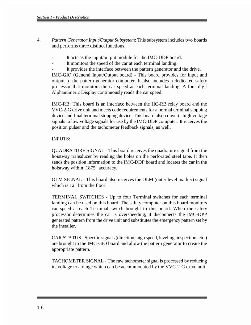
4. Pattern Generator Input/Output Subsystem: This subsystem includes two boardsand performs three distinct functions.
- It acts as the input/output module for the IMC-DDP board.- It monitors the speed of the car at each terminal landing.- It provides the interface between the pattern generator and the drive. IMC-GIO (General Input/Output board) - This board provides for input andoutput to the pattern generator computer. It also includes a dedicated safetyprocessor that monitors the car speed at each terminal landing. A four digitAlphanumeric Display continuously reads the car speed.
IMC-RB: This board is an interface between the HC-RB relay board and theVVC-2-G drive unit and meets code requirements for a normal terminal stoppingdevice and final terminal stopping device. This board also converts high voltagesignals to low voltage signals for use by the IMC-DDP computer. It receives theposition pulser and the tachometer feedback signals, as well.
INPUTS:
QUADRATURE SIGNAL - This board receives the quadrature signal from thehoistway transducer by reading the holes on the perforated steel tape. It thensends the position information to the IMC-DDP board and locates the car in thehoistway within .1875" accuracy.
OLM SIGNAL - This board also receives the OLM (outer level marker) signalwhich is 12" from the floor.
TERMINAL SWITCHES - Up to four Terminal switches for each terminallanding can be used on this board. The safety computer on this board monitorscar speed at each Terminal switch brought to this board. When the safetyprocessor determines the car is overspeeding, it disconnects the IMC-DPPgenerated pattern from the drive unit and substitutes the emergency pattern set bythe installer.
CAR STATUS - Specific signals (direction, high speed, leveling, inspection, etc.)are brought to the IMC-GIO board and allow the pattern generator to create theappropriate pattern.
TACHOMETER SIGNAL - The raw tachometer signal is processed by reducingits voltage to a range which can be accommodated by the VVC-2-G drive unit.

Section 1 - Product Description
1-7
OUTPUTS:
This system converts the digital speed pattern to an analog speed reference. Oncethis is verified by the on-board safety processor, it is sent to the VVC-2-G drive.It creates a speed signal which indicates the car is traveling over 150 fpm, whichprevents the car from leveling into a landing.
5. HC-RB (Relay Board): This board satisfies most of the code requirements forrelay contact redundancy. In addition, it satisfies requirements for normalterminal stopping devices. It also provides the necessary circuitry for operatingthe car on inspection or access, without the benefit of computers. In conjunctionwith the HC-PI/O board, this board comprises the high voltage interface betweenthe MC-MP computer and individual car logic functions such as door operation,direction outputs, direction sensing, main safety circuits, leveling circuitry, etc.See Figure 1.6.
6. SCR Drive Interface Board (HC-SCR): This board interfaces with the SCR driveand the SCR drive reset button. The M contactor coil is powered through thisboard. See drawing with -SCR as a suffix. The HC-SCR board contains thesensing circuits that protect the SCR drive from overcurrent conditions. Six wiresare brought from the resistor bank into TB1 (terminals 1 through 6) on the HC-SCR board. The HC-SCR monitors the voltage drop across the current limitingresistors connected to these wires. If an overcurrent condition is detected, thiscircuitry will trip the safety and shut down the drive.
7. Transformers: Transformers are provided, as necessary, according to the powerrequirements of each individual load and the available AC line.
8. SCR Drive: The SCR drive unit has four major components: the motor fieldmodule, control circuit board, firing circuit board, and a power module. The twocircuit boards are sandwiched together through a connector and the combinationcan be removed from the chassis. The DC contactor disconnects the DC loop.The DC overload opens up the DC loop when the current exceeds the safetythreshold.
9. Relays, Fuses, Terminal Blocks, etc.: Additional relays, fuses and terminals areprovided, as required, for other additional functions. These might be dooroperation, reverse phase sensing, safety functions, and so on.
10. VVC-2-G: The drive unit relays outputs to the SCR drive and brake from thevelocity signal generated by IMC-DDP board and direction signals produced bythe IMC-RB board. In addition it contains the emergency terminal stopping

Section 1 - Product Description
1-8
device, the inspection/leveling overspeed device, and tachometer monitoringcircuitry.
11. Resistor Cabinet: Any power resistor that generates significant heat such as doorresistors and SCR drive current limiting resistors, are in the power resistor cage.This prevents their heat from affecting other electrical components.
1.2 LANDING SYSTEM CONTROL BOX (LS-QUAD-2 or LS-QUAD-2R) - Models LS-QUAD-2 and LS-QUAD-2R Landing System Control Box are designed tobe mounted on the car top. Figure 1.7 shows the LS-QUAD-2 Landing System ControlBox. Each contains the following parts.
a. Two sets of tape guides which hold the perforated steel tape in exact alignmentwith the control box.
b. A pair of optical transducers which provide a quadrature signal for car position.
c. Leveling (LU, LD), Door Zone (DZ) and the Outer Leveling Marker (OLM)magnetic proximity sensors. For jobs with rear doors, the model LS-QUAD-2Rlanding system provides additional front and rear door zone sensors (DZF, DZR).
d. Magnetic proximity sensors for absolute floor position encoding (RD, PR, R0,R1, R2, R3, R4, R5).
e. A circuit board processing the sensor signals sent to the elevator controller. Allsensors have indicators on this circuit board. The quadrature signals and OuterLeveling Markers (OLM) are 50VDC; all other signals are 120VAC.
1.3 HUMAN INTERFACE TOOLS AND PERIPHERALS -
See Section 5 and the MCE Computer Peripherals Manual for detailed information.
1.4 GROUP DISPATCHER (two or more cars) -
See MCE Group Supervisor Manual.

Section 1 - Product Description
1-9
CAR CONTROLLER FUNCTIONAL LAYOUTFIGURE 1.1

Section 1 - Product Description
1-10
TYPICAL PHYSICAL LAYOUT VVMC-1000 SERIES TURBO DF SCRFIGURE 1.2
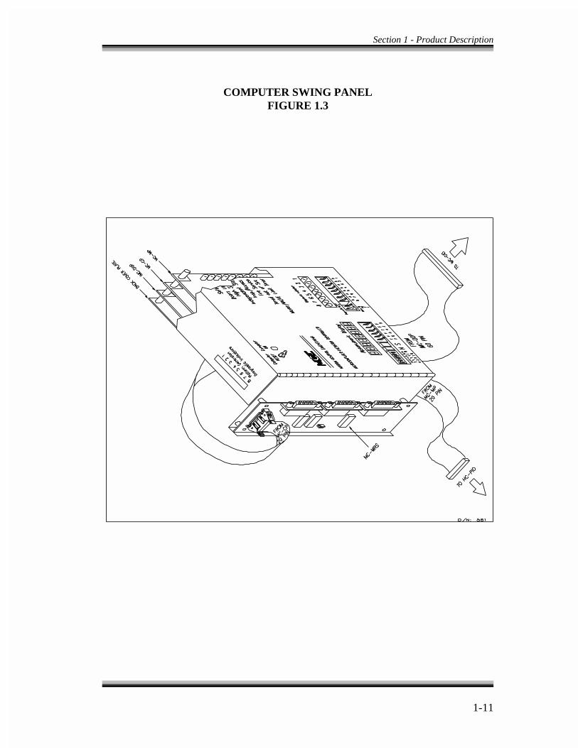
Section 1 - Product Description
1-11
COMPUTER SWING PANELFIGURE 1.3
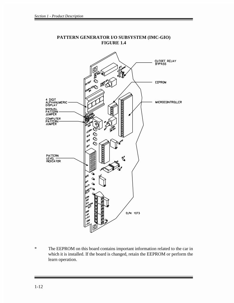
Section 1 - Product Description
1-12
PATTERN GENERATOR I/O SUBSYSTEM (IMC-GIO)FIGURE 1.4
* The EEPROM on this board contains important information related to the car inwhich it is installed. If the board is changed, retain the EEPROM or perform thelearn operation.
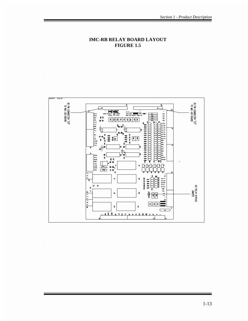
Section 1 - Product Description
1-13
IMC-RB RELAY BOARD LAYOUTFIGURE 1.5
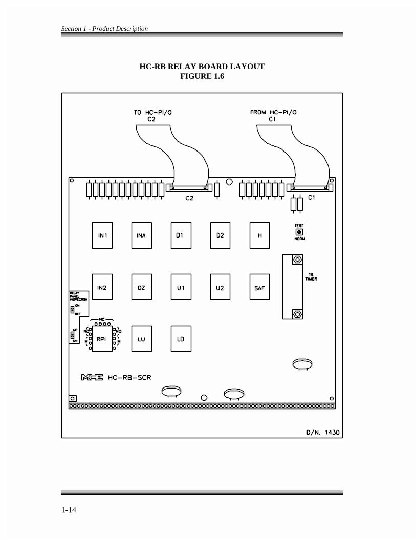
Section 1 - Product Description
1-14
HC-RB RELAY BOARD LAYOUTFIGURE 1.6

LS-QUAD-2 DETAILFIGURE 1.7
FRONT VIEW OF LS-QUAD-2
Adjust the level up (LD) and level down (LD)sensors by sliding sensor with a finger orscrewdriver. Do not open box to move them.Note that the LU and LD sensors must be thesame distance from the door zone (DZ) sensors.
REAR VIEW WITH COVER OFF
This shows the terminal strip on thefront of the HC-DFLS board used forcustomer connections.


2-1
SECTION - 2
INSTALLATION OF VVMC-1000 SERIES TURBO DF SCR CONTROLLER
2.0 GENERAL INFORMATION - This section contains important recommendations, instructions on site selection,environmental considerations, wiring guidelines and other factors which will help ensurea successful installation.
2.1 SITE SELECTION -
A proper location for the control equipment would have the following attributes.
- Adequate working space for comfort and efficiency is available.
- Logical arrangement of the equipment has been undertaken. The location of otherequipment in the machine room, proper routing of electrical power, and controlwiring has been considered. Note that MCE controls do not require rear access.
- The equipment is not installed in a hazardous location.
- Provision of space for future expansion has been provided, if possible.
- A telephone has been installed in the machine room. This is a desirable feature asit makes remote diagnostics available and makes any startup and adjustmentassistance easy if the installer is not familiar with the equipment.
- Areas in the machine room which are subject to vibration have been avoided orreinforced to prevent equipment cabinets from being affected.
- Adequate lighting in the machine room has been provided for the control cabinetsand machines. A good working area, such as a workbench or table, is also present.

Section 2 - Installation
2-2
2.2 ENVIRONMENTAL CONSIDERATIONS -
Here are some important environmental considerations. Adherence to these guidelineswill help prolong the life of the elevator equipment and minimize maintenancerequirements.
- An ambient temperature should be maintained which will not exceed 104� F.Operation at ambient temperatures of up to 110� F is possible, but notrecommended due to probable shortening of equipment lifetime. This meansadequate ventilation is required, and air conditioning may be necessary.
- The air in the machine room should be free of excessive dust, corrosiveatmosphere or excessive moisture so that condensation is avoided. A NEMA 4 orNEMA 12 enclosure may be provided to meet these requirements. If open windowsexist in the machine room, it would be advisable to locate cabinets away from thewindows so that severe weather does not damage the equipment.
- Very high levels of radio frequency (RF) radiation from nearby sources may causeinterference to the computers and other parts of the control system. Using hand-held communication devices in close proximity to the computers may also causeinterference.
- Power line fluctuation should not be greater than +/-10%.
2.3 RECOMMENDED TOOLS AND TEST EQUIPMENT -
For proper installation, the following tools and test equipment are recommended.
- Digital multimeter, such as a Fluke series 75, 76, 77 or equivalent- Oscilloscope, preferably storage type scope- Hand-held tachometer- AC clamp-on ammeter- Walkie talkies- DC loop ammeter- Assorted soldering tools, rosin flux solder, electronic side cutters and longnose
pliers, flashlight, MCE screwdriver (provided with controller)
2.4 INSTALLATION, WIRING GUIDELINES AND INSTRUCTIONS -
Proper procedures where wiring materials and methods are concerned is essential toobtain the best results in installations. Good basic wiring practices and ground

2-3
NOTE
Drawing Number Format - Each print in Section 7 has a DrawingNumber indicated in the title block. The first six digits (or positions) ofthis block contain the MCE Job Number. The seventh digit is theelevator car number to which this print refers. If the seventh position isthe letter G, this denotes the group controller. The eighth position is thepage number. If the eighth position contains the letters SCR instead ofa number, this denotes the drive page. In this manual the drawingnumbers will often be referred to by the eighth digit.
NOTE
Drawing Name - Some drawings have a drawing name directly abovethe title block or at the top of the drawing. The drawing name refers toa particular drawing.
requirements are discussed in this section and observation of the following will help toaccomplish this goal.
2.4.1 THE WIRING PRINTS - It is important to be familiar both with the followinginformation and the wiring prints provided in Section 7 of this manual.
- It is important to be familiar with Elevator Car Wiring Print drawing number (-1).
- It is important to be familiar with Elevator Hoistway Wiring Print drawing number(-2).
- Most of the power connections and non-drive related power supplies are shown ondrawing number (-3).
- The interface with the VVC-2-G drive unit is shown on drawing number (-D).
- The SCR drive and its interface is shown on drawing number (-SCR).
- Group interconnects to individual car cabinets (two or more cars) are shown on thedrawing entitled Group Interconnects to Individual Car Cabinets.
- Review additional wiring prints and details as provided.
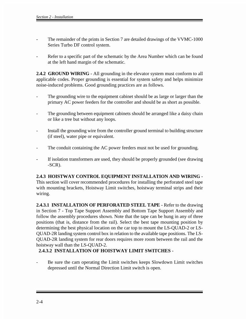
Section 2 - Installation
2-4
- The remainder of the prints in Section 7 are detailed drawings of the VVMC-1000Series Turbo DF control system.
- Refer to a specific part of the schematic by the Area Number which can be foundat the left hand margin of the schematic.
2.4.2 GROUND WIRING - All grounding in the elevator system must conform to allapplicable codes. Proper grounding is essential for system safety and helps minimizenoise-induced problems. Good grounding practices are as follows.
- The grounding wire to the equipment cabinet should be as large or larger than theprimary AC power feeders for the controller and should be as short as possible.
- The grounding between equipment cabinets should be arranged like a daisy chainor like a tree but without any loops.
- Install the grounding wire from the controller ground terminal to building structure(if steel), water pipe or equivalent.
- The conduit containing the AC power feeders must not be used for grounding.
- If isolation transformers are used, they should be properly grounded (see drawing-SCR).
2.4.3 HOISTWAY CONTROL EQUIPMENT INSTALLATION AND WIRING -This section will cover recommended procedures for installing the perforated steel tapewith mounting brackets, Hoistway Limit switches, hoistway terminal strips and theirwiring.
2.4.3.1 INSTALLATION OF PERFORATED STEEL TAPE - Refer to the drawingin Section 7 - Top Tape Support Assembly and Bottom Tape Support Assembly andfollow the assembly procedures shown. Note that the tape can be hung in any of threepositions (that is, distance from the rail). Select the best tape mounting position bydetermining the best physical location on the car top to mount the LS-QUAD-2 or LS-QUAD-2R landing system control box in relation to the available tape positions. The LS-QUAD-2R landing system for rear doors requires more room between the rail and thehoistway wall than the LS-QUAD-2. 2.4.3.2 INSTALLATION OF HOISTWAY LIMIT SWITCHES -
- Be sure the cam operating the Limit switches keeps Slowdown Limit switchesdepressed until the Normal Direction Limit switch is open.

2-5
- Be sure both the Normal and Final Limit switches are depressed for the entire run-by travel of the elevator.
- For faster elevators, the face of the cam operating the Limit switches must besufficiently gradual so that the impact of the switch rollers striking the cam face isrelatively silent.
2.4.3.3 INSTALLATION AND WIRING OF HOISTWAY TERMINAL STRIPSAND TRAVELING CABLES - The traveling cable must have at least one twistedshielded pair to be used for the position pulser quadrature signal from the landing systembox (LS-QUAD-2 or LS-QUAD-2R) and shielded cable should be used all the way to thecontroller. If two or more shielded pairs are still available, route the two OLM signalsfrom terminals 93 and 94 in the landing system box through a shielded pair (especiallyif there are more than eight floors). The shield is best grounded only at the controller.
2.4.4 ELEVATOR CAR CONTROL EQUIPMENT INSTALLATION ANDWIRING -This section covers the recommended procedures for installing and wiring thelanding system box (LS-QUAD-2 or LS-QUAD-2R), magnetic strips on the steel tape,TM switch on the car top (if used) and diode installation details for certain dooroperators.
2.4.4.1 INSTALLATION OF LANDING SYSTEM CONTROL BOX (LS-QUAD-2or LS-QUAD-2R) - Refer to the drawings in Section 7 - Option #1, and Option #2 ForMounting Landing System Box to Elevator Crosshead, and Option #1 and Option #2 ForConduit Knockout.
- An ideal location should have already been selected for the landing system box instep 2.4.3.1 above.
- There are holes on both sides and on the bottom of the landing system box formounting to support brackets or structural channels. The mounting of the boxshould be firm and solid so that it cannot be knocked out of alignment. Use ¼"diameter screws with 20 threads per inch.
- To install the tape into the tape guides on the LS-QUAD-2 landing system box,remove the two thumb screws on the two guide assemblies, insert the tape andreinstall the guides with the thumbscrews (tighten firmly). For the LS-QUAD-2Rlanding system box, remove the three 8-32 screws holding the protective 1" widechannel covering the back of the door zone sensors on the upper tape guidebracket. Then remove the single standoff which is in the way of the thumbscrewholding the tape guide. Now remove the thumbscrews holding the upper and lowertape guides, insert the tape, and reinstall the guides with the thumbscrews (tightenfirmly). Reinstall the standoff (don't overtighten) and the protective channel.
- After inserting the steel tape into the tape guides, check the position of the landingsystem box. The car should be at the top of the hoistway, making it easy to see if
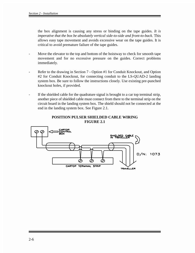
Section 2 - Installation
2-6
POSITION PULSER SHIELDED CABLE WIRINGFIGURE 2.1
the box alignment is causing any stress or binding on the tape guides. It isimperative that the box be absolutely vertical side-to-side and front-to-back. Thisallows easy tape movement and avoids excessive wear on the tape guides. It iscritical to avoid premature failure of the tape guides.
- Move the elevator to the top and bottom of the hoistway to check for smooth tapemovement and for no excessive pressure on the guides. Correct problemsimmediately.
- Refer to the drawing in Section 7 - Option #1 for Conduit Knockout, and Option#2 for Conduit Knockout, for connecting conduit to the LS-QUAD-2 landingsystem box. Be sure to follow the instructions closely. Use existing pre-punchedknockout holes, if provided.
- If the shielded cable for the quadrature signal is brought to a car top terminal strip,another piece of shielded cable must connect from there to the terminal strip on thecircuit board in the landing system box. The shield should not be connected at theend in the landing system box. See Figure 2.1.

2-7
NOTE
The magnetic strips provided with the LS-QUAD-2 or LS-QUAD-2Rlanding system may be either north or south pole types (usually south).The poles marked indicate the side away from the adhesive side. Themagnets should always be attached to the steel tape from the adhesiveside.
- If the OLM signals from terminals 93 and 94 in the landing system box are routedthrough shielded cable as suggested in step 2.4.3.3 above and if the shielded cablefor the quadrature signal is brought to a car top terminal strip, the wiring methodshould be similar to that shown in Figure 2.1.
2.4.4.2 INSTALLATION OF MAGNETIC STRIPS ON THE STEEL TAPE -
a. Carefully read and follow both the Target Installation instructions in the prints inSection 7 and the remainder of these instructions before proceeding.
b. Before installing the magnets, clean the steel tape thoroughly with an appropriatesolvent. No oil should be left on the tape as it will interfere with the adhesivebacking on the magnets.
c. There are normally two lanes of magnets installed on the facing side of theperforated tape. One lane consists of individual floor magnets (leveling magnets)only, which are each 6" long. The other lane consists of the binary targets (absolutefloor position encoding magnets) which are all multiples of 2½" (e.g., 2½", 5", 7½"and 10") in length. The edge and preset magnets are all multi-pole magnets and areused only as installation guides.
d. Floor magnets which operate the LU, DZ and LD sensors should not be installedpermanently because they may have to be readjusted. Use clear Scotch tape fortemporary installation. Install permanently R0 through R5 and PR magnets,provided the car is positioned within ¼" of the floor - this is extremely important.Extreme care is required for the installation of these magnets. If this procedure isnot carried out precisely all the magnets may have to be reinstalled during the finaladjustment.
e. If there are rear doors, the LS-QUAD-2R landing system has additional door zonesensors on the rear of the upper tape guide assembly. Follow the Target Installationinstructions on the prints in Section 7 and install the 7½" long front and rear doorzone magnets on the rear of the tape (the side facing away from the landingsystem). These magnets may be permanently installed at this time.

Section 2 - Installation
2-8
CAUTION
Do not remove protective covering from boards until it is time to bringwires into the terminals.
Do not allow any metal chips to fall into the electronics.
2.4.4.3 TM SWITCH WIRING AND ADJUSTMENT (IF USED) - Refer to theElevator Car Wiring Print in Section 7 for details on the wiring and setting of eachcontact in the TM switch. Carefully examine the functioning of this switch, especiallyif copper to carbon contacts are used. The current levels are quite low and may not beenough to burn the oxide off of the contacts.
2.4.4.4 DOOR OPERATOR DIODE INSTALLATION (IF USED) - Certain dooroperators such as G.A.L. type MOM or MOH require the installation of diodes in thedoor operator on the car top. See the Elevator Car Wiring Print in Section 7 for specialinstructions regarding these diodes.
2.4.5 MACHINE ROOM CONTROL EQUIPMENT INSTALLATION ANDWIRING -
2.4.5.1 CONTROLLER INSTALLATION - Here is a guideline for installing thecontroller cabinet(s).
- First mount the controllers securely to the machine room floor and cut holes tobring wires into the cabinet. See Figure 2.3 - Controller Board Layout - TypicalExample for recommended hole locations. There may be labels also in the cabinet,for identifying areas for wiring hole locations. Note that the standard MCE carcontrol cabinet does not require rear access and the doors are reversible andremovable for ease of wiring.
2.4.5.2 CONTROLLER WIRING - Figure 2.3 shows the recommended routing for thefield wiring. Perform the following steps.

2-9
a. The wires used should be brought in from a location which allows use of thewiring duct inside the control cabinet. The terminals are located conveniently nearwiring ducts.
b. When routing field wiring or power hookups, stay away from the left side of theHC-CI/O and HC-PI/O boards.
c. When it is time to hook up the wires to the controller, remove the protective coversfrom the boards and interconnect the wires according to the hoistway and carwiring prints.
d. If the car controller is part of a group, a separate conduit or wiring trough must beprovided for the high speed serial link from each car controller to the groupcabinet.
e. Main AC power supply wiring size is determined by the electrical contractor.Proper motor branch circuit protection is provided according to the applicableelectrical code in the form of a fused disconnect switch or circuit breaker for eachelevator. Each disconnect or breaker must be clearly labeled with the elevatornumber.
f. If the car is part of a group, there are several additional details relating to thewiring of the group cabinet and its interconnects to the individual cars. They areas follows.
1. If a group controller cabinet is provided, refer to the Group Supervisor FieldWiring Print in Section 7. If a single phase AC main power source for thisgroup controller is specified on this print, a correctly sized (according to theapplicable electrical code) fused disconnect switch or circuit breaker mustbe used which draws its power from the same AC bus that powers theindividual elevator cars. If more than one bus is available and one is anemergency power bus, use the emergency power bus so that during switch-over to emergency power, the group logic is also on emergency power.
2. The wiring details for the high speed communication link are fully detailedin the drawing in Section 7 - Instructions For Connection Of High SpeedCommunication Cables and they should be followed exactly. Again note therequirement for routing the high speed interconnect cables through a separateconduit or wiring trough.
3. If applicable, also wire according to the drawing in Section 7 - GroupInterconnects To Individual Car Cabinets. Be sure to ground all cabinetsaccording to Section 2.4.2 above.
4. The field wiring to the group supervisory cabinet is found in the drawing inSection 7 titled Group Supervisor Field Wiring Print.

Section 2 - Installation
2-10
2.4.5.3 DC HOIST MOTOR WIRING -
a. Be sure to follow all notes on the schematic regarding the possible rearrangementof the motor field. This could involve splitting the field in half which could entailhaving to find the proper wire inside the motor to make the split. Use #14 wire sizeminimum on all field wiring from controller to motor field (and brake if currentlevels require it). Follow wire size guidelines in prints.
b. The armature wiring must be brought to terminals A1M and A2M in the controlcabinet. For details of armature wiring refer to drawing (-SCR).
2.4.5.4 ISOLATION TRANSFORMER WIRING - Make sure that wire sizes areproperly selected to comply with applicable codes. For details of isolation transformerwiring, see drawing with (-SCR) as a suffix.
2.4.5.5 TACHOMETER INSTALLATION AND WIRING -
a. Be sure that the tachometer wheel (for gearless applications) is running on aprecise surface (i.e., brake drum surface, etc). Any vibration of the tachometer willcreate vibrations in the car.
b. Do not get the tachometer close to a magnetized area (motor field winding, etc.)because it will cause the car to have different speeds while going up or down, eventhough the tachometer puts out the same voltage in both directions.
c. Alignment of the tachometer coupling is extremely important for geared machines.In general, most vibration problems come from the tachometer and/or its mounting.It is important that the tachometer mounting is very rigid and that the coupling isperfectly aligned before adjusting the drive unit. In a geared installation do notdrive the tachometer from the sheave because the gear lash cannot be compensatedfor by the drive unit.
d. Vibration caused by the tachometer cannot be corrected inside the drive. Roughsurfaces, either on the tachometer wheel or where the tachometer wheel runs canalso cause vibrations. Remember that the tachometer must connect to the motorthrough a coupling or by a follower wheel.
e. Do not run the tachometer directly from a gearless motor in such a way that thetachometer rpm equals the motor rpm. Always use a follower wheel for gearlessapplications.
f. Use a twisted pair shielded cable to connect from the tachometer to the controllerterminals TS and TC. Do not connect the shield at the tachometer end but insulate
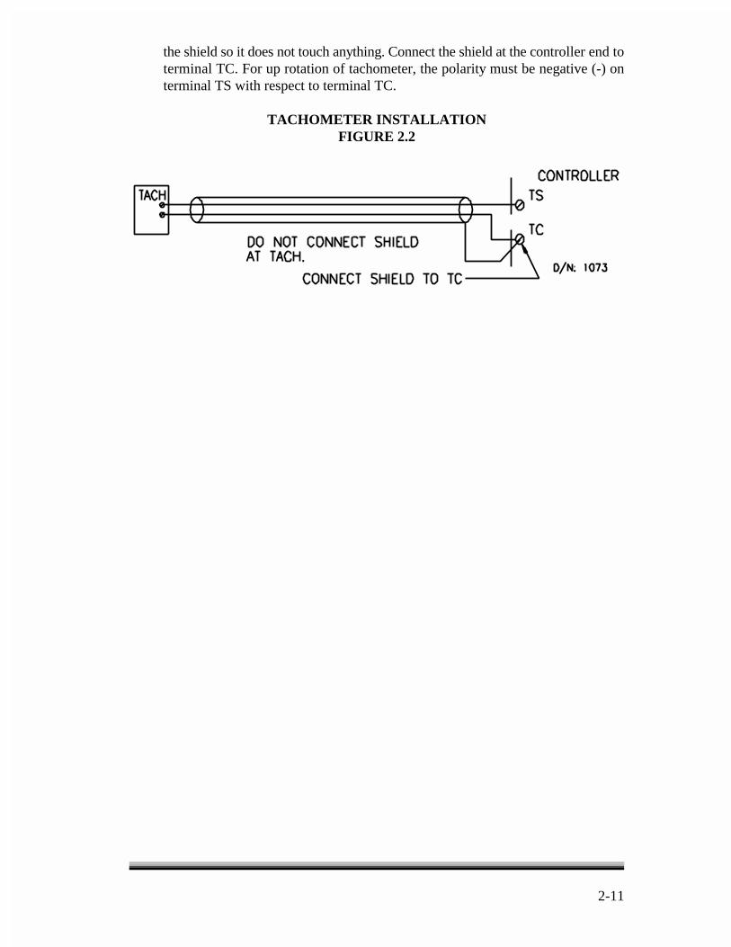
2-11
TACHOMETER INSTALLATIONFIGURE 2.2
the shield so it does not touch anything. Connect the shield at the controller end toterminal TC. For up rotation of tachometer, the polarity must be negative (-) onterminal TS with respect to terminal TC.
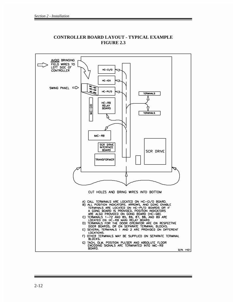
Section 2 - Installation
2-12
CONTROLLER BOARD LAYOUT - TYPICAL EXAMPLEFIGURE 2.3

���
���������
������ ����� �����������������������
�������� ��������������������������
3.0 GENERAL INFORMATION -
����������� ������������������������������������� ���������� ���������������������������������������������������������������������������������������������������������������������������������������������������������������������������� ���� ��� ��� !����� ����� ��" ������ ��� ���� ������ ���� ���� ��������� �������������������������������������������������������������������������������� ����� � ����������#��

��$
�������
����% �����������������������������������������&''(�������������������� �������������������������������������������������������������������� ���� ������ ����� ���� �� �� ��� � ��� ������ �" ���� )���� % ��������������� ���� ���� ������� ���� ������ ��� ���� ���������������� �� ������������������ ��������� �������������% �������)���������������� ����
�� ���� �������� ��� �� �� � � � �� � ��� ���� ��� �� ������� *�#� ��� ����������������������������� ���� ������������� ���������������� ��������������������������������� �� ��������!������������������ ���������% ���������������������������������������������� �������������������
$� ���������������������������������������������������������������������������� ������������������������������������������ ����������" ��������������+�� ����% ����� ����������������������������% �������� ��� ����������������� ���
�� ������ ��������������������������������� ��������������� ����������!�������������������������� � ������ ��� ������
,� ������������������ ���������������� ������� ���������������� ������ ����
� � ���������� � ������� ����� ���� �� ����� � +������� �� �� ���� ������� ������ ������% ����������������� �����������-���������.��������������� �������� ����������������������������������������������������� ������� ���������������������������
3.1 GROUND CHECK -
�� /�� ������������������������������������ �����������������������������/�� ��������� ���� ���0����������������������������������������� �������������������������������1�� ��2���������������������������*������$��������� ���
�� � ���� ����������� ����������� ������� ����� �������������#��������.� ����$����������+������3��� ��((4���'''�*����� �����.�*�#�����.� ��$���������������/�����3��� �����������5-����������������������������������������������� ������� �������������

5GEVKQP � � 5VCTV 7R
���
����
�������������������������� ��������������������������''�����
�� 6���������������������� ��.,����������� ��������������������������������� ������������� ������� ������������������������������ ���������������������������������$7�����$.�
$� ���� �������� ���������������������������������������7��#/�1��������2�������������������������������� ��������� ���������������89�
�� ���� �������� �������������������������7��+�:)�����7����:)�������
,� ���� �������� ��������������.���.$��!���!$������&�����;�!�3��4)�������������������������#������������ ��.<�����.8��3�� �������������������������������������� ������������"���������.�������������������������� ����������������������� ������������������������� ������������������������������ ���
&� ���� �������� ��������������3�3��3$3��3�3��!�4��!$4��������*�#�������������������� ��������������4.���4.$������/������/$�������� ��������������#�������� �����������������$7�����$.�
3.2 SCR DRIVE INFORMATION -
/������ ����������� �� � ��������� ��� ��� ������� ���� ���� ��������� �����������������
�� ������������������������������������������������������*����*�#����� �������� �������������������� ���� ��� ���� ����7��*�#� ������������������������������������������������������������������������������������������"���������������������� ������������� ��-�1�*�#2�
�� �������������������������������������*��������������*����*�#��������� ���=�������������!""#$������#"#$���" �������������*�#������ ���������
�������������������� ����������������������" �������������� ������� �����������������

5GEVKQP � � 5VCTV 7R
��,
����
!�� �������*����*�#��������� �����������������������*������� ����������������������������������*�#������ ����������������������������������������������������� �����������������4�5������������������� ������ ������������������*65)��� ���� ����� ��������� ������� ���� ���������� ���� ��" ����������������-������������������������������*�#������ �������������� ������������ ���� ���������� ��� ���� ������� *���� *�#� ������� �������4�5�������������������������� ����� ������ �������� ������� ��� ���� ���� ���� ���������� ���� ��" ������ ��� ������������������������������������
�� ������������������������������� ����������� �������*�#������������������������������������������:)� �������1��������������������2������������������1��2������
3.3 BEFORE TURNING ON THE POWER -
�� #��������������� ����������������� ��������� ��������������������������� ���������������� ����% ������������������������������������� ��������� ����� ��� ��� ���� ������ ���� ��� ������� ���� ������ ����� �������� ����� ������
��� ������������������� ���������� ������������� �������������������
�������������������������������� ������������������ ��������������������������������������������������
�� ���� �����+��������/ ����������������������������*������������������������������������������������������������ ����������#�����+��������������������������������" ����������������������8�����&9��������������������3��������������������������� ����������������������� ����������������7��������� ���� ������������������������������������������� ����
�� 6�������������� ��������������������������������������������������������4��4+�/������������7��+�:)�/����������������������������7��+�:)�/������������������*����+���������� ������������������������������

5GEVKQP � � 5VCTV 7R
��&
�� >��� ����������������������� ����������7��+�:)�����7����:)��������������� ���� ���� � ��������� ���� ����� ���� ������� ���� ������ ���� ���������������� �� ����� ��� ���������������������������������������������� ��� ��� ���������� ������� ��� � �� �� ������ ��� �� ������ � � ��� ���������$��������,���������������������������������������� ��������)��� ����������������������������������+����������������������������������������������������������� ��� �����
�� ������������������������" ����������������������� ���� ���0�������������������������������������������������������������������������� ���������������������������������� ������������������������ ������
�� ����������" ����������,����8��������������������� ��������������������������������������������" ����������$�����?��� ������������" �������������������!�������������" ������������������$'@����$�@��������((��$�;����� �����������������������������" ��������������������� ���
��������������������� ����������)������((��$�;������ ����� ��������������������������5��3**��/����*+���*�!3��5*������3)���������� ���� ����� �������� ����������������������� ������������������������������ ���!������ ��� ������� � ��� ������� �������� ��� ������ � ��� � ����=����� ����� ����/��������������� �������������������������� ��������������������������������������������������� ���1��������������������� �������2��7��������� �� ����" �����������1��������������������2� ������������������)��������������������������*�#������ ������������������������������������������������� ����������
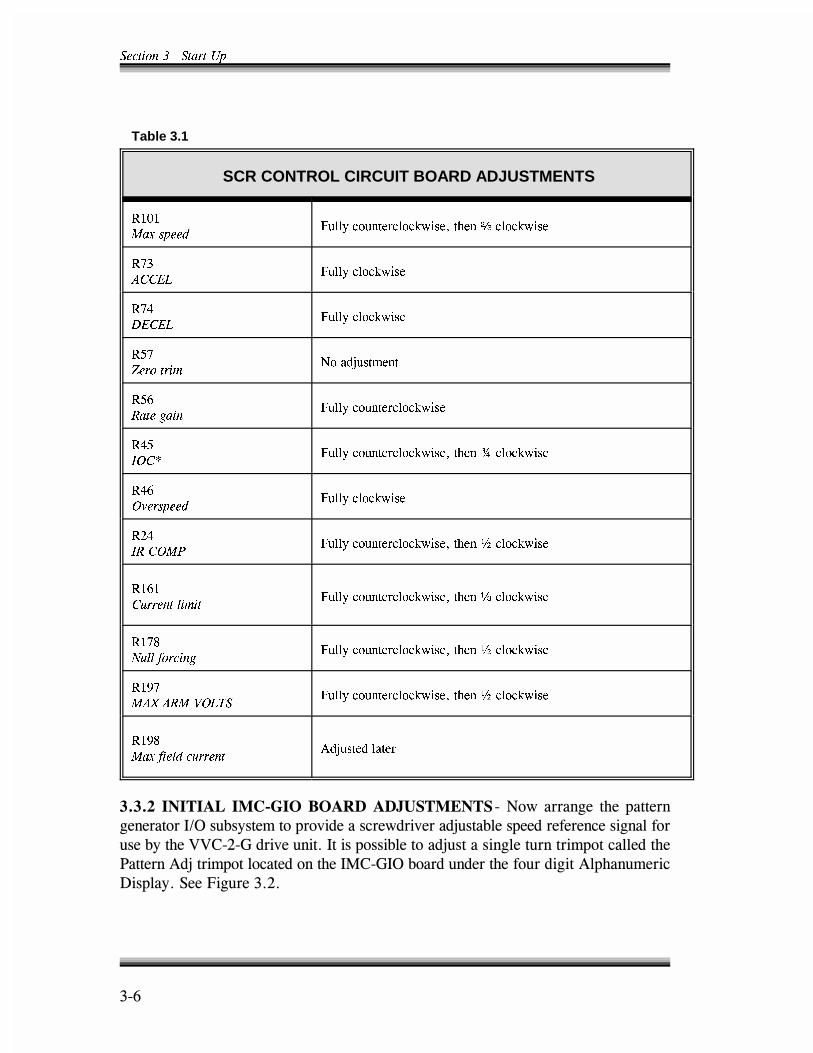
5GEVKQP � � 5VCTV 7R
��?
Table 3.1
SCR CONTROL CIRCUIT BOARD ADJUSTMENTS
4���
/CZ URGGF(WNN[ EQWPVGTENQEMYKUG� VJGP E ENQEMYKUG
4��
#%%'.(WNN[ ENQEMYKUG
4��
&'%'.(WNN[ ENQEMYKUG
4��
<GTQ VTKO0Q CFLWUVOGPV
4��
4CVG ICKP(WNN[ EQWPVGTENQEMYKUG
4��
+1%�(WNN[ EQWPVGTENQEMYKUG� VJGP � ENQEMYKUG
4��
1XGTURGGF(WNN[ ENQEMYKUG
4��
+4 %1/2(WNN[ EQWPVGTENQEMYKUG� VJGP � ENQEMYKUG
4���
%WTTGPV NKOKV(WNN[ EQWPVGTENQEMYKUG� VJGP D ENQEMYKUG
4���
0WNN HQTEKPI(WNN[ EQWPVGTENQEMYKUG� VJGP � ENQEMYKUG
4���
/#: #4/ 81.65(WNN[ EQWPVGTENQEMYKUG� VJGP � ENQEMYKUG
4���
/CZ HKGNF EWTTGPV#FLWUVGF NCVGT
���� ������������������������ ����������=����������� ����������������������:)� ������������������������������" ����������������������������� ���������((��$�;������ �������������������" ���������� ��������������������+�������!�"������������������������4��;�)������� ����������� ������!����� �����������*���.� �����$��

5GEVKQP � � 5VCTV 7R
��<
����
������������������������������������������ ���������������������������������13�7��3$7������3�7��������2��������������������������������!���������������*�#������13�3��3$3������3�32�
�� 3�����������4��;�)�������������������������������������������� ����*���+������#��������.� �����$������������������������" ������� ��A+,�����A+&�������� ����������� ���������������������������+�������!�"���������������4��;�)����������������� ������A+&���������� ������������������������� ��������������� ������������� ������A+,�������������'����B�&(������������������� ��������'C��������������������������������� ���������������������������+ �������� �����A+,�
�� � �������+�������!�"����������������4��;�)�������� ������ �������� ����
�� �����4��;�)���������������� �������������������������������� ��������������������!�������������������������������������������" ������� ����A+��1� ��)���#�����/���2����������=��������������������./���������A+���������������������� ����������������������������� ��)���#�����
3.4 POWER APPLICATION -
�� ���� ���������� ��.,��������������� ��.<�����.8��������������3�� �������������������� ��.3,�����.3&���������1��2�����������������������������������������������������������������������������������((��$�;������ ����� ������=��������������������� ����������#�����+��������������������
�� ���� �������������������������������������������������������������������������������
�� � ���������������������������������������� ����������������3���3$�����3���������������� ��������������/�� ��������������3��3$�3���������*�#�������������������������������������������������������������������������������������������������������� ������������������

5GEVKQP � � 5VCTV 7R
��8
����
6������������������� ������������������������ �������� ������� ��� �������������� ��������������������������������� ��������������� ������������������������������" ���������������� �������4�-.����� �����������������% ���������� �������" �������� ������������������������������������������������������������ ������� ���������������������� ����������������� �� ����������������������������������������������������*�#�������������������������������������������������������� ���������������������
�� � �������������������������� ��.,��.3,�����.3&������������ ����������������������((��$�;������ ���������������������� ��� �����������������������������������"���������������������������������������������������
�� � �����������������������������������������������#�������������������*�#������������ ��������������������������������������������������� �����������������������������������������������3������3$��������������������������!��3��������������������������������������#�������������������������������
�� =����������������������� ������� ��D��=+��������7��*�#��������*!.����#+���������7��#/�����������*!.������������� ������������=������������������ ��������������������������*!.������ ������������������ ��������
������������������ ����
�� �������������������������������������&9���������������������������� �������=������������������������������������������������������ ���������������������!��������������������" �������������������8�����&9��������������#+������������� ������#+��������� ���� ����������������������#�����+������������������������� ��
�� /������������������������������� ������3����������� ������ �������� ���������� ������� ��������������� ������������������ ������������������������������������������ �������=�������������#������������������!������ ����������1$&'(�������2�����������������������4.������4.$��������������������� ���
5GEVKQP � � 5VCTV 7R
��9
�� � ����������#�����+������������������������ ������ �:�������� �������� �������������������� ���� ������E�����*�#������������������� ����������������4������������� ����� ���������*�#������� ������3���35������� ��������� ����� ������3��� ������� ������ ������� ���� ��� ��� �������������% ��� �� ����������������������� ��������������������������� ������3���������������� �������� ���������������������������A����������������A���'1����� ���� ������� ��� A��<� ������2� ��� ���� *�#� ������ ��� ���� ���������������������������������������������������������������4����������������������������� ������������������� ��������������=�� ����������������������������� �������������������������������������������� ���������� �����3������������ ���������������� ������������������������������������������������4�������� ���� ������� ����� ��������������������������������������������)������������ ���������������������������������������������������*�#�����������#�������������������+ ������#����� ������������7��*�#��������������#����������� �����������������������������
�� 7���� ���� �:��� ����� �� ���� �������� ���� ������ �������� ����+�������!�"���������������4��;�)����������� �������������� ���������������������������� �:����������������������������������� ������������������������������������������������������������������������������������������������������������������� �������������������������������������������� �������������������$'��'������!�" ��#����;����������*�#��������������������������"�������������������������������)���������������������������������� �����������������������������������#�����+������������������ �:���������
�� 6�������������� ��������������*�#������������������������ ����������������������� ���������������������������4.������4.$��������������������� ����� ����������� ���� �*�#��������� ���������� ��� ������ �������������������� ���� � ���������� ����� ����������������� ����� ��������� �������" ����������12������� ����������
�� (����������������� ����� ����������������������������� ����������������� �������������� �������� �����������������������
����� ���������� ��� ����� ��� ����������� ���������� �� � �����������������������������������% ���������������
�� >��F�>$�1������F��$2������������������������������������������� �
5GEVKQP � � 5VCTV 7R
���'
�� >!��F�>!$�1����!��F��!$2������������������������������4��#/��������� ������������������� ��+�����+������� ������������������������9-����<-���8-������������� ���1����������������������� �������������������� ��� ���� ���������2�
�� +�����/����������������������������� ���������7��*�#������������� ������*�#����������+�����������������������������#����������������4��������������� ������4�������������������� ����� ������#�����������������*�#��������������!��������������4��/������*!./�� �������� ������� ��=+����������������������������������������������������������� ����������� � ���*!./��/���*!.������/6������� ���
�� #�����)*��� ���������������������������������������������*�#��������������������� ������������������������������� ���������������������*�#������������������� ��������� ����������������)*����������������������� ������������ ����!������ ���������������������#�������������A$���������*�#���������������������# ���������������7��*�#������������������������ ������4������������������ �������������������������������+�������!�"���������������4��;�)�������
�� ���������% ���������������>��F�>$�1������F��$2��������� ���>!��F>!$�1����!������!$2��������������� ���������������������������������� �����������((��$�;������ ���������� �����������1�������2��������������G���������+���������������������������������������������� ����������+������/�������+������/���������� �������������� ��/���� ��������� ��������+�������/���������������������������������� ������������������������/������������������((��$�;������ ����5���� ������/��������������� ��������� ��� �� ���� ��������������������� ����((��$�;������ ��� ����������������������������+�������� ��������*�#������������������������������ ���������� �����
������ �������������������������������
�� +�����������������������������������������������������������������#�����" ����� ����� �������� $� ���� �?� ��� ����7��#/������� ���� ���� ������ �������� ���4� ������� ������ ��������������������*������������ ����������*!.����*!.@�������������������(��������������" ������������������������8����&9�����������!������� ������������������� ������������������������������������*�������������������� ����������

5GEVKQP � � 5VCTV 7R
����
�� # ������������������������������������������ ������� �:���� ������������*���������
�� # �������������� ������������������� ������������������������� ��6������������������� ���������������" ���������������������� ���������
�� (���������������������������������������.����3����������)������������������������ ����������������((��$�;������ ��������������������������*����������������������������������������������������� ������������������������������������������" �����. �������������������������" �����������������$'@����$�@� ��������((��$�;������ ������������������������������������0���� �
�� )��"���������,'H������������� ������������� ��������� ����,'H����������������������� ������% �������������� ���� ������ ����� ������������������������������������������������1��������������������������"�������������� ����������� ������ ��� ����2�� ��� ��������� � �������� ��� ���� ����� �������������������
��������������������������������� ������ �����������������
�������������� ���������� �������������� ����������������% �������% ����������������������" ��������� ����� ������������������������������
� * ���������� ���������������������$&H��������������
� !������% �������������������������
� !�������������������&'���������� ��������1���������������"�����2
� !����������������������� ������������������������������
� !������% ���������������������������������������������������������������������������������������������������������������������������
����������������������������������������������������������*�#������ �� ��� �������G������� ����((��$�;� ����� ���� ���� ����� ��� �������� ����������������������,@��������������������������&@��������((��$�;������ ����!�
����������%������� �������������&�' (�� �)* *+�,&�-���.������-�� ��/ �

5GEVKQP � � 5VCTV 7R
���$
�� # ��������������������������������+�������!�"����������������4��;�)�������� ���� ����������������� ����� ������� �������� A��?� 1/ ����� ��� ��B2����������������������A��&�1/ �������� ���2�����������������������������*�#��������-�������(��14� �������-�������������� ���������������������#������������B�I� �E�������I������2
�� *�������4�-�*��������������������*�#�������������'�8'(����A���'���������������A��<��������" �����������!�" �������������������������� ������������'H���������������������������� ���� ��������������-������� ����������
�� !���� � �� ���� ���� ��� �������� ������� ��� ���� �������� ��� �������� A���'1*���������������� �2�����������������������A��<�1������2����������������������������*�#��������������������� ������'�8(�B:��'�'&(�1������������0�������2������������������������������� ���������������������� ��������� ������������A��?�����A��&�
���������������������� ���
�� ������������������� ���������������������������� ������������������������������ �������� A��?� ���� A��&����� ���� ����� �% ������� �� ������ �������� ����������������" ����������������� �������������������� ���������������������� ���������� ��������������������������������������������������������������������������������������1�������������;�!�3���������������2�
�� 4� �� ��� ���� ������� ���� ���� ����� ���� ������ ���� ��� ���� # �� ���� �������������� �������������������� ��������������������������������� ������ ����������������������������������������������� �����
�� =���� ���$&H����� �������������������������������������������������� ���������������� �������������������0����������������� ����������������� ����
� ���������������� �1�4� ��������������" ������������ ��������������������������������������������5���������*�������������������������������� ��� �������� ������ �������� ���� ��� � �� ���� � ��� ����� �� ���� �������������� �������� ������3�����������������*�#�������
,� #��������������������������������������������������
����������������������� ���
�� ����������� ����������������������������" ���������������������$'@����$�@��������((��$�;������ �����������*������������������������������������������������� ������ �����������" �����������������
5GEVKQP � � 5VCTV 7R
����
����
#�������� ��������������������������������������" ������
�� � ��������������=����������������7��#/��������������������������� ����������7��#/����������������������������������������� �����=����������� ���������������������������&9��� ����������#�����+����������������������������������� �:�������������� ���������������
�� *������������������������������������������������G����1�J��������� ��2���������������� ������� ���������������������� ���������
3.5 PREPARATION FOR FINAL ADJUSTMENT -
�� � ����������������������������������#����������������������������������4��4+���������������������������7��+�:)��������+��������������������������������������� ������������������������7��+�:)�������� �����������������������������������������������������������������+����������������� ����������������������������������������������� ������������������=���� ��������������������
�� �������� ����� ��������������������������������������������������������������������� ����*����+������*���.� ���&����/���������������*������&�$�$���������������������&�<�����&�8���4��4+�/�����*��� �����������4����+�/�����*��� �������
�� � ��� ���� ����=���� ����� ��� ���� �� ������ ��� ��" �� ���� ��������� ���� ��������������������������������������������� ���������� �����
�� ����������������������������������" ��������������������������� ����������������������������������7��������" ����������������������������� �������������� �����������������������������������������������������" �������������������������������� �������" ���������������#�0�.������������������� ��������������������
�� +���������������������������������������������������7��+�:)�������������������������������7����:)��������!����� ��������������������� �� �������������������������������������� ����� ������ ������ ���������������
5GEVKQP � � 5VCTV 7R
���,
�� ����
4����������������������� ������������������������ ������������������ ����� ���� ��� ����� ��� ��� �������� ���� ���� ��� ������������������������ �������������������� ��������������������������������� �� �� ��� ����� ������������� ��� ������� ���� ����������������������������������������������������������������������� ������ ���� � ����������������������� ������%����������� �
�������������������� ������ ���������������������������������� ��������� ���������������������� ���������������������� ��������������� ���������� ������������������������� ���� ��� �� ����� ����������� ��������� �������������������������������������������������������� ����� ����������������� ����K��'''�������������% �����L
����� ��������� �� ���� ����� � ���� ������ ���� ������������� �� ���� ����� �����������������"��������������������������������������� �������������� ������������ �����1���� ��������7����:)�=2������ �� ����������������������������������������������������������������35��������������������������������������6�������������� ������ ������� �������������� �
�� )��������������������������������������������" �����������������������6����� ������� ��� ���������� ����������������������������������������������������������G��������������� ����������������������������������������������M���������������������������������������������� �������������� ����������� �� � ������ ��� ����� ����� ��� �� ������� ���������� ���������������� ���������������������������� ��������������������:���
�� =����������� ��� ��" �� ���� ������� ��� ���� ���� �� ���� ������ ���� ������� � �������������������������������� ����������� ���������� ���" �����������������*�������+�������!�"����������������4��;�)����������'��(������������+����������������)4������� ��������������-�����$'��������������.����������" ���������� � ��������������������������������������������������������������������������������������������������������������*�����������������������������������������������������������������������������������)4����������������������������������������������((��$�;������ �����������������������������������������������
5GEVKQP � � 5VCTV 7R
���&
�� 4��������" ������� �������A+,����A+&�����������������4��;�)����������������+�������!�"����������������������������������������E������������������������ ���������+�������!�"������������ ��������������������� ��$'�����!�" ������*+��1������� ������2����������������((��$�;������ �����������+�������5�������������������" ����������� ������������������� ���� ��
� ���������������������������������������������������*�#�������!�" �������� ������������ ��� ������ ���� ��� ���� ���� ���������� ��� ���� ����������#��������������� ����������������� ��� ���������������������������������>����������������������������� ��������" �������������������
��� #&?�#!�5� ;!�=� �� !�" �� ����� ����� ����� ���� ���� �� ��������
��-� �� ����� ��� ����������� ����� �������� ��������� ��� �������������������� �������� ������������������������������������ �����"��������������������������������������������������������������������������������������������������������1 �2����������������� ����� ��� ����� �� ������ �������� #���� ;��� ���� ��� �� � ��� ������������������������������������������������������� ���������"�����������������������������
$� #$,��#��)4+���!������������������ ��������������� ���� ������ �������� �������������������������������% ���. ����� �������� ��������������������� ������������������� �������������� ������� �������������
5GEVKQP � � 5VCTV 7R
���?
�� ����
!�����������" ��������*�������������������������������������� �����" ������� ��������������������������
� . ��.<�����.8���������������������
� A ������� ��A+���� ��������������./���������������4��;�)������
� ���� " ����� ���������� �������� ,�8� ��� ���� 7��#/� ������� ��������������
� ���� " ����� ���������� �������� $'@�$�@� �� ��� ���������������
� ����" �����������������������$��?��� ��������������
� !�" ������� ���� �������������A+&���������������4��;�)������
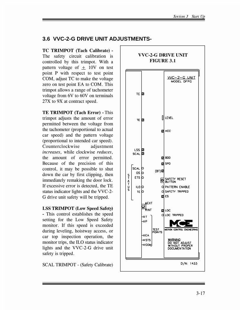
5GEVKQP � � 5VCTV 7R
���<
������������ ���
��� �����
3.6 VVC-2-G DRIVE UNIT ADJUSTMENTS-
����������� !�"#$��"%&'(")*+�
���� ������ ��� �� ���������� ����������� ��� ��� �������� 6��� ��������� �������� ��� B� �'(� ��� �������� +� ���� ������� ��� ���� �����)4����" ���������� �������������G����������������5!�����)4���������������������������������������������������?(����?'(�����������$<@����9@������������������
�����������!�"#$��((,(+����������� ��" �� ���� ��� ��� ��� �������������� �������� ������������ �������������������1������������������ ������ ����2� ���� ���� �������� �������1�������������������������������2��� �������� ��� ��" ������������������� ���� ��� ����������� ��� ��� ��� ������ ���������/��� �� ��� ���� ������� ��� ����������� �� ���� ��� ������ ��� � ����������������������������������������������� ��������������� �����-���������������������������5��� ����������������������((��$�;������ �����������������������
������������!�,-��.**/��"0*)1+
� ��� �������� �������� ���� ���������� ���� ���� 3��� *����� *������������� ��� ��� ����� � �-������� �������������������������������� ���� �������� ���������� ��������������������3)���� ������������� ���� ���� ((��$�;� ����� ����������������
*�!3��#�4+)����1*��������������2
5GEVKQP � � 5VCTV 7R
���8
���� ������� ���" ���� ��� ������� ����� �������� ���� ��������� �����B:$H���������������" ����������������*�!3�35����������������������������������������� ��������������G������������������� �������*�!3�������� ��������*�!3�����������������!����� �� ����������-� ������������� �������������������������������N�� ������������������6������� ���� ���� ������" ��������������� ���������-� ��������������������������������������� ��������������������������������������� ���������������)*�����5�*���� ���������
���������������!�"0*)1��"%&'(")*+���*�����������������������*�!3������������������������������������������������������������$H������������������������������*�!3�����������" ��������������
�������������!�&2$��.**/��3*(4.**/2�����������������������&H������������������������������������������������� ���������������������������)*�������������������������������������� �������������)*�������������������������������" �������������*�!3��������1��������2�
��������������!�5*(2*6#1��*(5&6"%��),..&62��*3&#*2����������������������9&H��������������������������������������������5�����������������*�������3����������������������$8@����$9@��������������������������������������������������� ���������������� ��������������5�*���������1������������*�!3�������������������" ���2�
��������������!�64.*#)&,6�"6/��*3*%&62��3*(4.**/+��������������������-���������������������������3**��������1�&'����������2�������3)���� ������������������������������������������������������
�������������!�"#$��((,(+�������������������������������� ��������������5�������������������� �������������������������������� ��������
�������������!�"#$+�����������������������������1����� ���2��2����������� ����������������������������������������������������������������
�������������!�"))*(6��&26"%+��������������������������������������������������������������������������-��������'(��% �������������������1B�I� �E���I����2�
��������������!�((,(��5.%&0&*(+���������������������� �� ��������������������������������������������������������������������+��������������������������������������������������������������������������������������������1+2�������������1�2�����������������
5GEVKQP � � 5VCTV 7R
���9
���������������!�16)$*4&7*/��"#$��&26"%+��������������������������� ������������" �������������4�������4(������������������������7��*�#�������������������������" �������������������������������������������������54.�������������������������������������� ����������������������������������������% �����������������
���������������!�,55,6+������������������������������������������������������������������ ������������������������������������������������ �����������������)4������������������������9@�
������������������6��������������@�����������������������9@�������������� ��� ������������������������������� ��������6��������� �����������������3)�1����������3������������)�������2���� ������������������
������������!�##*%*(")&,6��")*��&5&)*(+����������������������" �������������������� �����������������������-� ����������G����������������������-� ������������� ����� �� ��� ���������� �����������������6��� ���� �������� ��� � ����� �������� ��������������% ����������-������������������6��������������� �������� ��������������� ��'�&��������
�������������!�("8*��(,.��*%"1+����������������������" �������������������������������������������������������� ����������
������������ !�.**/����*%"12� ����� �������� ������ ���� ������������� ������������� ����������������������������:)� ��������������� ���������������������������<&������������ ������������� ������������������������������������������������������������������������������� ������������� ��������� �������� ��������������������������������������������� �������!����������������������������������������������������������$$@�����$�@��������((��$�;������ ���
���!�("8*��(&5��,6)(,%+����������������������������-� ��� �� ������������ ��������������� ������������" ����
�����9�������� ����������� �������������������������������������((��$�;������ ���������������������������������������������1)*���5���3)����5�*2�������� ����������������������� ����������������������������������+ �������� ������������������������������������������������������������������������������ ������������������$'@�����$�@�
��������������������������������� �������������������35��������������������������������������������������������������������������$$@����$�@������������������������������������ �� ���������������������*+���������

5GEVKQP � � 5VCTV 7R
��$'
�����9��������������������������� �����������������35������������������������������� ��������������������������������������
�����������!�%*#)(&#� �),.��,6)(,%+� �� ��� �������� �� �� �� � ��� ��� �������������������������������������������������������1���������� ���������2��4������� �������������������������� �� ��� ������������������" ����������������������% � ����. ����� �������� ��������������� �������� ����������������������������������� ������
������������!����,,.��3*(#:((*6)��,6)(,%+��������������������������������������������� ������������������������������������������������������ ����������������������������*����*�#������������� �������� �����������$&@����9@��. ������ �������� ����������������3)��������������������������� ������������������� ������������� ��������������������� �������������������������������� ����������3)�������������������������*���������������������������������������������������������������$'@�����$�@�
�������������������������������35���������������������������������������� ���������������������������������3)��������������������-�������� ������ ���������������������������������������*�#���������������������������� ������*������������������������������
Table 3.2
VVC-2-G DRIVE UNIT TRIMPOT SUMMARY
6TKORQV &KTGEVKQP 4GUWNV
6% %NQEMYKUG +PETGCUGU 6 VQ UGV '#�18 YKVJ ��8 QP 2� &QGU PQV CHHGEV ECT URGGF�
6' %NQEMYKUG .GUU FKHHGTGPEG CNNQYGF DGVYGGP VJG VCEJ CPF RCVVGTP XQNVCIG�
.55 %NQEMYKUG &GETGCUGU OCZKOWO URGGF FWTKPI KPURGEVKQP� CEEGUU CPF NGXGNKPI�
5%#. %NQEMYKUG %CNKDTCVGU 15 CPF '65 UCHGV[ EKTEWKVU 5%#. .'& NKIJVU CV JKIJ URGGF��
#%% %NQEMYKUG (CUVGT TCVG QH EJCPIG QH URGGF UKIPCN KP GOGTIGPE[ UNQYFQYP�
$&& %NQEMYKUG .QPIGT FGNC[ DGHQTG DTCMG FTQRU�
52& %NQEMYKUG .QPIGT FGNC[ DGHQTG QPUGV QH URGGF UKIPCN RCVVGTP�� #NNQYU OQTG VKOG HQT
DTCMG VQ RKEM�
$6 %NQEMYKUG .GUU DTCMG XQNVCIG�
'5 %NQEMYKUG 5VTQPIGT DTCMKPI RWNUG CV UVQR�
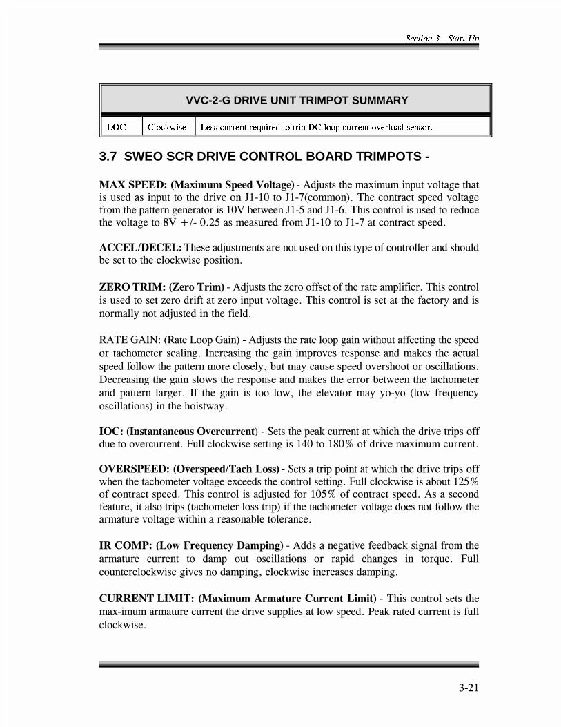
5GEVKQP � � 5VCTV 7R
VVC-2-G DRIVE UNIT TRIMPOT SUMMARY
��$�
.1% %NQEMYKUG .GUU EWTTGPV TGSWKTGF VQ VTKR &% NQQR EWTTGPV QXGTNQCF UGPUQT�
3.7 SWEO SCR DRIVE CONTROL BOARD TRIMPOTS -
��;������<�!�"=&5:5��.**/��,%)"2*+���!�" ��������-� ���� ��������������� ������� �����������������A���'����A��<1������2��������������������������������������������������������'(���������A��&�����A��?�������������� ��������� �����������������8(�B:��'�$&������ ���������A���'����A��<�������������������
�����>�����<��������" �������������� ���������������������������������� ������������������� ���������
?��������<�!?*(,��(&5+���!�" ������G������������������������������������������ ���������G������������G������ ������������������������������������������������������������" ���������������
#!�5�;!�=D�1#����3����;��2���!�" ������������������������ ����������������������������������������������������������������������������� ��������� ���������������������������������������� �������� ������������������������������������������������������������������ ���������������������������������������������� �������� ��� �������� � ���� ����� ����������������������� 1�������% ������������2��������������
���<�!�64)"6)"6*,:4��3*(#:((*6)2���*���������� �� ������������������������������� ���������� �������. ������� �����������,'�����8'H�����������-� ��� ������
���������<�!�3*(4.**/>�"#$��,44+���*�������������������������������������������������������������������-������������������������. ������� ������� ���$&H��������������������������������" ���������'&H�������������������!������������ ��������������1�����������������2������������������������������������������������� ���������������������������������������
�������<�!�,-��(*@:*6#1��"5.&62+���!�������������������� ������������������� ��� � ������ ��� ����� � �� ��������� ��� ����� ������� �� ���% ��� . ���� �������� ���������������������� �����������������
� �����������<�!�"=&5:5��(5"):(*��:((*6)��&5&)+����������������������-�� ������� ���� ��������������� ������������������+�� �������� �������� ������ ���

5GEVKQP � � 5VCTV 7R
��$$
��;������ ��������<�!�"=&5:5��(5"):(*��,%)"2*+����������������������-� ������� ������������������������������������������������������������������������������������������ ��1����� ����������������������2��������������������������������������������������� ����������������������������������� ������������������������������������������-� ������� ������������������������������������������ ���������� ������������������������������������������������������������������������������������� ��������������������������������� �������������������������������1���������$,'(��2��6���������������������� �������������� �����" �����4.6���������������7��*�#�������
��;�������� �����<�!�"=&5:5��&*%/��:((*6)+���!�" ��������-� ������� ����������������������� ��� ������������������������������������������������������4�-�!���� ���(������������� ������ �� �� ��� ��������� ����� �� ������������ ������������" ������������������ ��������" �������G�������������������������������5�������" �������� ������������������������������(�=�I�'''����G���������
� ��� �������<� !�:%%� �,(#&62+� �� !�" �� ������� �� ��������� ����� ��������������������� ��������������������1� ��������2���������G�������������������� ������������������������������ �������������������������� ���� ���� ������� ��������������E������������������������������������� ���
Table 3.3
SWEO SCR DRIVE TRIMPOT SUMMARY
6TKORQV &KTGEVKQP 4GUWNV
+1% %NQEMYKUG +PETGCUGU QXGT EWTTGPV VTKR RQKPV� 5GV YJGP CEEGNGTCVKPI WR YKVJ
C HWNN NQCF�
18'452''& %NQEMYKUG +PETGCUGU QXGTURGGF VTKRRKPI XGNQEKV[�
+4 %1/2 %NQEMYKUG +PETGCUGU FCORKPI VCMGU QWV QUEKNNCVKQPU��
4#6' )#+0 %NQEMYKUG /QTG NQQR ICKP CPF VKIJVGT TGURQPUG� %CP ECWUG QUEKNNCVKQPU KH
VQQ HCT ENQEMYKUG�
<'41 64+/ %NQEMYKUG (CEVQT[ UGV� FQ PQV CFLWUV�
#%%'.�&'%'. %NQEMYKUG 0QV WUGF UGV CV HWNN ENQEMYKUG��
/#: 52''& %NQEMYKUG /QTG OCZ URGGF XQNVU QP ,���� YKVJ TGURGEV VQ ,���� 5GV VQ �8
HQT EQPVTCEV URGGF�
/#: #4/ 81.65 %NQEMYKUG +PETGCUGU OCZKOWO CTOCVWTG XQNVU�
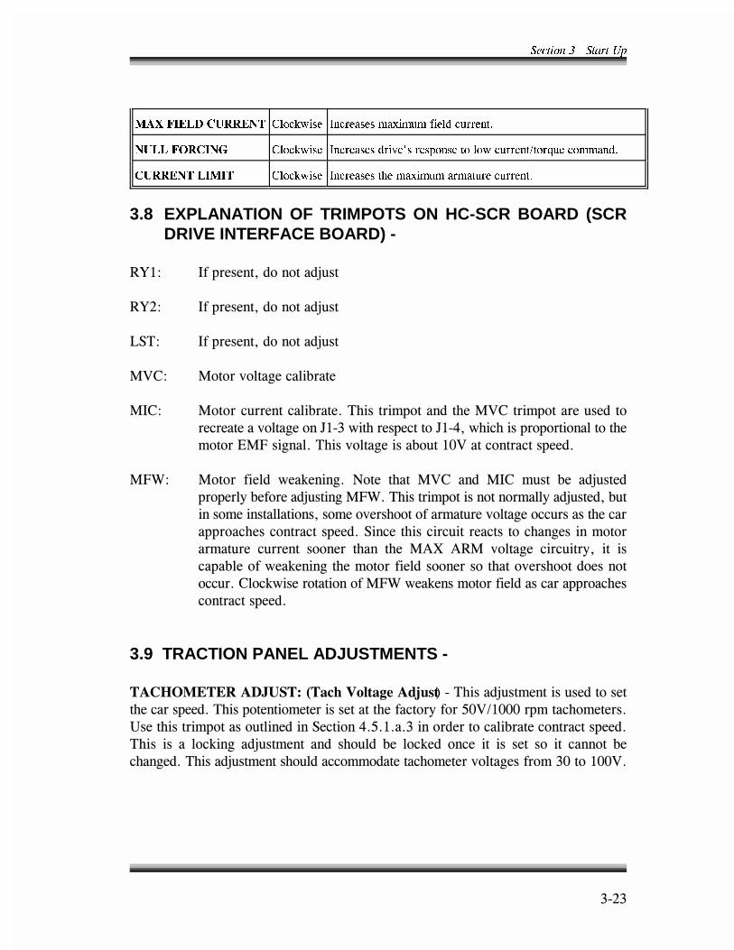
5GEVKQP � � 5VCTV 7R
��$�
/#: (+'.& %744'06 %NQEMYKUG +PETGCUGU OCZKOWO HKGNF EWTTGPV�
07.. (14%+0) %NQEMYKUG +PETGCUGU FTKXGU TGURQPUG VQ NQY EWTTGPV�VQTSWG EQOOCPF�
%744'06 .+/+6 %NQEMYKUG +PETGCUGU VJG OCZKOWO CTOCVWTG EWTTGPV�
3.8 EXPLANATION OF TRIMPOTS ON HC-SCR BOARD (SCRDRIVE INTERFACE BOARD) -
#O�D ��������������������" �
#O$D ��������������������" �
3*�D ��������������������" �
4(�D 4���������������������
4��D 4������ ����������������������������������4(������������� ���������������������������A������������������A��,��������������������������������54.���������������������� ���'(������������������
4.6D 4����� ����� ��� ������ =���� ����� 4(�� ���� 4��� � �� ��� ��" ���������������������" ����4.6����������������������������" ������ ��������������������������������������� �������������� ������������������������������������*���������� ������������������������������ ��� � ������ ������ ����� ���� 4!@� !#4� �������� ��� ����� �� �������������� ���������������������������������������������������� ������� ��������������4.6���� �������������������������������������������
3.9 TRACTION PANEL ADJUSTMENTS -
�������������� ��<�!�"#$��,%)"2*��/A:4)2��������" ������� �������������������������������������������������������������&'(:�'''����������������>��������������� ��������*������,�&�������������������������������������������� � �� ��� ��� ��" ������ ���� �� ��� ��� ��� ��� ����� �� � ��� �� �� ������� ����������������" �������� ����������������������������������������'�����''(�
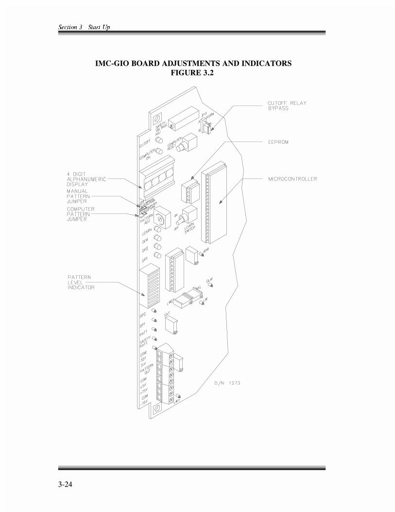
5GEVKQP � � 5VCTV 7R
��$,
���������������� ����������������������
��� �����
4-1
SECTION - 4
FINAL ADJUSTMENT FOR MCE'S VVMC-1000SERIES TURBO DF WITH SWEO SCR DRIVE
4.0 GENERAL INFORMATION -
At this point, Section 5 should have been read and all the steps in Section 3 completed.Section 4 describes the sequence of steps necessary to complete the final adjustment ofthe elevator system. At this time, all fuses should be in place. All jumpers, except thejumper wire connecting terminals 20X and 21X, should be removed.
4.1 SET UP OF CRT TERMINAL -
The CRT terminal should now be installed. Refer to the MCE Computer PeripheralsManual for installation instructions. Also see Figure 4.2 - MC-MRS Link to CRTterminal.
a. Once the CRT is installed, turn on the CRT terminal power switch. When theCRT is turned on, it is important to remember that it must be initialized. Press F5on the keyboard to begin the initialization process. When initializing the terminal,the screen goes blank and may flash a couple of times before showing a readabledisplay. Initialization takes about ten seconds and configures the WY-60 orequivalent terminal to meet MCE requirements for communication and displaycharacteristics. If problems arise in the CRT display functions because of powersurges or line noise, reinitialization of the terminal generally clears the problem.Reinitialization of the terminal is listed on the main menu. Once the terminal hasbeen initialized, the main menu is displayed on the screen. When this occurs, alldisplay functions are available to the operator with a single key stroke. Each mainmenu function can be accessed directly from any other main menu function. It isnot necessary to return to the main menu in order to enter a different displayscreen. Once the operator becomes familiar with the function key definitions,accessing information on the CRT is easy.
b. Press function key (F1) on the CRT terminal keyboard to display the DigitalDrive Parameters screen. Adjust and verify the speed parameters which defineand describe exactly how the car moves between any two landings. Initial valuesfrom the factory are a combination of calculated values and values obtained byexperience, but they are only provided as a starting point. For typical values ofspeed parameters consult Table 4.2.
Section 4 - Final Adjustment
4-2
c. As mentioned before, speed parameters are stored in EEPROM non-volatilememory. When the IMC-DDP software reads from the EEPROM, it checks thevalidity of the data. If the data are not valid, the software creates an EEPROMread error (EPRD). Some important considerations regarding the EEPROM areas follows.
- If an EEPROM chip is replaced on the IMC-DDP board, it is likely thatthe new chip is either blank or contains wrong data. In this case, ignorethe EEPROM read error. Proceed with the learn operation.
- If the EEPROM read error (EPRD) is encountered, reenter the speedparameters. Reset the IMC-GIO computer after the data are reentered toverify that the new data are stored in the EEPROM. Note that resettingthe IMC-GIO processor is only necessary if the EEPROM read error wasencountered. In the normal course of changing the parameters, it is notnecessary to reset.
d. If the data are incorrect, or if changing a parameter is necessary, take the stepsbelow.
1. Put the car on inspection using the Relay Panel Inspection switch.
2. Observe the cursor on the screen under the Desired Values column.
3. The desired parameter(s) are reached by using the TAB key on the CRTterminal keyboard.
4. Once the cursor is on the parameter to be changed, use the right or leftarrow key to select the digit of the parameter.
5. Once the digit of the parameter is selected, use the I/D key on the CRTterminal keyboard to increase or decrease the value of the digit. Whenchanges are made to the digits of the parameters in the Desired Values,the changes are made permanent by hitting the S key. When Are YouSure? (Y/N) appears, hit the Y key. The Y key saves all the values in theDesired Values column to non-volatile memory (EEPROM). Once thedata are saved in the EEPROM, Actual Values and Desired Values arethe same if the data entered were within the acceptable range. If any ofthe parameters were not within the acceptable range they are not saved,and the value shown in the Actual Values column will be default values.
Section 4 - Final Adjustment
4-3
If the combinations of the parameter entered are not valid, the CRTdisplays a message saying This Combination Of Parameter Values IsUnacceptable. There are three possible reasons for the system to considerthe parameters unacceptable. Pattern Generator Trouble-shooting, inSection 6.4, goes into this in greater detail. Possible reasons forunacceptable parameters are as follows.
a. The parameters entered do not allow proper generation ofstepping points in the hoistway.
b. There is a short floor in the building to which the system cannotrespond.
c. Within the given parameters, the computer cannot generate a twofloor run pattern. Note that if the system cannot generate a onefloor run pattern it would consider that floor a short floor andcreates a custom short floor pattern for the specific floor.
4.2 RUNNING THE CAR ON INSPECTION UNDER COMPUTER CONTROL -
a. No LEDs or readouts on the Computer Swing Panel should be illuminated.
b. Turn on power at the main disconnect. The Relay Panel Inspection switch shouldbe on and the Computer On light on the upper left corner of the Computer SwingPanel should be lit. The IMC-DDP processor board which creates the digitalpattern signal should be functioning properly. To determine that it is, observe theDDP Computer On indicator at the back of the Computer Swing Panel. If theindicator is on solidly, the IMC-DDP processor board is functioning. If theComputer On indicator is off, flashing, or flashing very slowly, the IMC-DDPprocessor board is not functioning properly. If this is the case, check the EPROMsocket to verify proper insertion and orientation of the EPROM chip. If the SAFrelay on the HC-RB board is energized, then the Safety On indicator in thevertical row of indicators on the right side of the Swing Panel must beilluminated.
c. The Inspection switch on the elevator car top must be in the Normal position.This places 120VAC on terminal 59 with respect to terminal 1. With the PatternAdj trimpot on the IMC-GIO board all the way clockwise, run the car, using theRelay Panel Inspection up/dn switch, and verify that the car speed isapproximately 50 fpm.
Section 4 - Final Adjustment
4-4
NOTE
The building floor heights must be successfully learned prior to runningthe elevator on automatic operation.
d. Verify that there is a jumper plug on JP5 on the IMC-GIO board. See Figure 3.2.
e. Verify USD/DSD inputs to the HC-PI/O board for proper operation at terminallandings. To find the proper place in the schematics look at area 9 of theindividual elevator job prints in Section 7 and find the USD and DSDdesignations at the left margin of the page. Then follow to the right to identify theterminal numbers corresponding to the 120VAC sources for these signals. Thebest way to verify that these signals reach the MC-MP processor board is to usethe Enhanced On-Board Diagnostics (the EOD) described in Section 5. Setswitches A2, A3, A4 and A6 up. All other switches should be down or off. Thesecond LED is for the USD flag. The sixth LED is for the DSD flag. Now run thecar on inspection to the bottom landing and verify that the DSD input signal isoff at the bottom. Run the car to the next landing above the bottom, and observewhen the DZ relay energizes. Verify that the DSD input signal is on. To verifythe USD input signal, run the car to the top landing and observe that the USDinput signal is off. Run the car down to the next landing below the top, watchingthe DZ relay (or DZR relay if there are rear doors) to verify that the USD inputsignal is on. Correct any problem with the Limit switches feeding the USD andDSD inputs at this time before proceeding. Also, program in, or verify, thenumber of landings, contract speed, inspection speed and leveling speed on theF1 screen of the menu.
4.3 HOISTWAY LEARN OPERATION -
Learning the building is defined as recording the location of each floor in the buildingrelative to the bottom floor within .1875" accuracy. This is accomplished by reading theholes in a perforated tape as the elevator travels the entire length of the hoistway fromthe bottom to the top. Take the following steps.
a. The car must be on Relay Panel Inspection.
b. On the IMC-GIO board, place the JP3 jumper plug in the TFB position.
Section 4 - Final Adjustment
4-5
c. Move the JP4/JP5 jumper plug on the IMC-GIO board from the manual pattern(JP4) position to the computer pattern (JP5) position.
d. Pull the Level Down wire out of terminal 25 at the bottom of the HC-RB relayboard. Place jumper plug on JP1 jumper pins located on the upper right cornerof the IMC-RB board above the CSB relay so the two pins are connected byjumpers.
e. The contract speed (VH) and the number of landings (NL) displayed on the CRTmenu F1 (shift F2 for simplex) must correspond to the particular elevator beingworked on. If VH and NL are not correct values, change them. Section 4.1 (d)describes how to change parameters in this screen. Once the proper values of VHand NL are displayed on the Actual Value column of this screen, proceed withthe learn function. The speed during the learn operation is the same as theCorrection Speed or VCR parameter. A good value for VCR is 50 fpm. Displaythe F3 screen for help in the learn operation. It displays car motion and the countsfor each floor as the building is learned. It also displays error messages that mayoccur during the learn operation. Disregard error messages from the EEPROM.They are caused by the fact that the building has not yet been learned.
f. Move the car on inspection below the bottom landing door zone (DZ) and intothe level up (LU) position by connecting a jumper from terminal 8 to terminal 12(Down Normal Limit), and by connecting a jumper from terminal 2 to 16(primary safety circuit), if necessary. Notice that the F3 screen on the CRT mustdisplay LU but not LD or DZ. A thorough knowledge of the EOD in Section 5is necessary, especially 5.2.2.3, for viewing inputs and flags. It is essential thatDSD remains off when the car is below the floor. On the F3 screen, verify thefollowing conditions.
USD (Up Slowdown) = ONDSD (Down Slowdown) = OFF
g. Now the system is ready for the learn operation. Set the diagnostics to the systemmode. Refer to Section 5.2.4. Put the system into the learn operation by followingthe instructions in Section 5.2.4.2. The Alphanumeric Display on the ComputerSwing Panel should say LN READY. If the system is not ready to learn, theAlphanumeric Display would indicate LRN ERR, and the Diagnostic Indicators onthe lower right hand corner of the Swing Panel would flash the error conditionthat is causing the learn error message. In case of error indication, refer to Table5.2 and Table 5.8 in Section 5 for a complete listing. When error conditions areeliminated, the Alphanumeric Display will show LN READY.
Section 4 - Final Adjustment
4-6
h. With the Alphanumeric Display indicating LN READY, learn the building byrunning the car the full length of the hoistway by holding the HC-RB Relay PanelInspection switch in the up position. The Alphanumeric Display indicatesLEARNING. Do not release this switch until the word LEARNED is displayed on theAlphanumeric Display and Learn Complete is on the CRT F3 screen. Prematurerelease of the up switch would cause LRN ERR (learn error) to appear and thesystem would have to be brought out of the learn operation and the car sent to thebottom of the hoistway again. The learn operation would then have to bereinitiated. In case of difficulty in achieving the LN READY display, turn offswitches F4 and F7 on the Computer Swing Panel, wait ten seconds and thenreenter the learn operation as in step (g) above.
Note that as the car moves very slowly up on inspection, the quadrature positionpulser indicators labeled DP1 and DP2 on the front of the IMC-GIO board flashon/off. The proper sequence of the status change of the DP1 and DP2 pulsers isimportant.
1. DP1 Turns ON2. DP2 Turns ON3. DP1 Turns OFF4. DP2 Turns OFF
This sequence goes 1, 2, 3, 4, 1, 2, 3, 4, in the up direction and 4, 3, 2, 1, 4, 3, 2,1 in the down direction. If the pulsers are out of sequence, the DP1 (terminal 95)and DP2 (terminal 96), are wired backwards and must be swapped at terminals95 and 96.
i. Individual floor heights can be verified by multiplying the floor count displayedon the F3 menu of the CRT terminal by .1875" to arrive at the height in inches.To make sure proper values are displayed on the CRT screen, press the F3function key on the CRT terminal keypad after the learn operation is complete.
j. When Learn Complete flashes on the CRT and the Alphanumeric Displayindicates LEARNED. Wait a few seconds to allow the IMC-DDP computer to storethe learned data into the EEPROM. The F3 screen may still indicate some errormessages. These error messages are probably related to the motion parameters.Nevertheless, continue with the steps.
k. Remove the system from the learn operation by toggling F4 and F7 switches onthe front of the Swing Panel to the off position.
l. Turn off the individual car power disconnect. Replace the Level Down wire intoterminal 25. Remove the JP1 jumper from the IMC-RB board. On the IMC-GIOboard, place the JP3 jumper in the Norm position.

Section 4 - Final Adjustment
4-7
m. Remove the jumpers from terminals 2 to 16 and 8 to 12. Turn on the main powerdisconnect switch for that car.
4.4 VERIFYING ABSOLUTE FLOOR NUMBERS -
All the floor magnets should have been installed on the perforated tape as instructed inSection 2.4.4.2.
a. Turn on the Diagnostic On-Normal switch on the Computer Swing Panel.
b. Dial up the diagnostic switches to address 21. The A1 and A6 switches shouldbe up; all other A switches are down. The Pattern Generator DiagnosticIndicators on the top of the Swing Panel are now arranged to display (startingwith indicator 8 and ending with 1) from left to right as follows.
RD - PR - R5 - R4 - R3 - R2 - R1 - R0
c. Move the car on inspection to the bottom landing. Stop the car so that the RDindicator shown above is illuminated. This indicates that the RDU and RDDsensors on the LS-QUAD-2 or LS-QUAD-2R landing system are centered on theleveling magnet. Note that the DZ relay must also be energized. If the LS-QUAD-2R landing system is being used, rear doors are present. Therefore, one or theother, or both, of the DZ or DZR relays must be energized, as well.
d. Starting at the bottom, run the car to each floor and verify the indications exactlyas shown in Table 4.1. Do not proceed beyond this step until the exact indicationslisted above have been achieved. Failure to do so results in incorrect floorposition indication and erratic operation. Verify that when the RD indicator is on,the DZ relay is energized on the F3 screen, or on the HC-RB relay board (it wouldbe DZR relay on the HC-RDRB rear door relay board, if the job has rear doors).If obtaining the proper indications presents difficulties, investigate the following:missing magnets, wiring mistakes and/or a defective sensor. A defective sensormay be tested manually by moving a magnet near the sensor and observing theLED indicators inside the LS-QUAD-2 or LS-QUAD-2R landing system box. Ifit should be necessary to run the elevator slowly to position it, turn on the RDindicator, and turn the Pattern Adj trimpot counterclockwise temporarily.
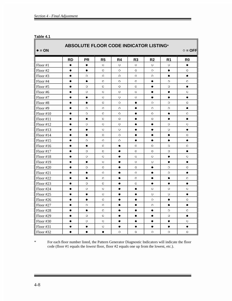
Section 4 - Final Adjustment
4-8
Table 4.1
ABSOLUTE FLOOR CODE INDICATOR LISTING* �� = ON �� = OFF
RD PR R5 R4 R3 R2 R1 R0 Floor #1 � � � � � � � �
Floor #2 � � � � � � � �
Floor #3 � � � � � � � �
Floor #4 � � � � � � � �
Floor #5 � � � � � � � �
Floor #6 � � � � � � � �
Floor #7 � � � � � � � �
Floor #8 � � � � � � � �
Floor #9 � � � � � � � �
Floor #10 � � � � � � � �
Floor #11 � � � � � � � �
Floor #12 � � � � � � � �
Floor #13 � � � � � � � �
Floor #14 � � � � � � � �
Floor #15 � � � � � � � �
Floor #16 � � � � � � � �
Floor #17 � � � � � � � �
Floor #18 � � � � � � � �
Floor #19 � � � � � � � �
Floor #20 � � � � � � � �
Floor #21 � � � � � � � �
Floor #22 � � � � � � � �
Floor #23 � � � � � � � �
Floor #24 � � � � � � � �
Floor #25 � � � � � � � �
Floor #26 � � � � � � � �
Floor #27 � � � � � � � �
Floor #28 � � � � � � � �
Floor #29 � � � � � � � �
Floor #30 � � � � � � � �
Floor #31 � � � � � � � �
Floor #32 � � � � � � � �
* For each floor number listed, the Pattern Generator Diagnostic Indicators will indicate the floorcode (floor #1 equals the lowest floor, floor #2 equals one up from the lowest, etc.).
Section 4 - Final Adjustment
4-9
e. If the F3 screen of the menu is selected, move the car through the floor and viewthe LU, DZ and LD indicator on the CRT screen.
4.5 RUNNING ON AUTOMATIC OPERATION -
The next steps cover completion of the elevator system adjustment for proper operation.These steps also cover checking contract speed, door operation and all other functionsprovided on the elevator.
a. At this time, the safety function of the IMC-GIO board is bypassed, becausejumper plug JP3 is in the TFB position on the IMC-GIO board. This means thatthe Terminal Limit switch protection is bypassed. The Alphanumeric Display onthe IMC-GIO board acts as a digital tachometer to indicate the car speed, whenthe Learn switch located on the IMC-GIO is off. When the controller is shippedfrom the factory the IMC-GIO has completed the learn operation. If the car cannotrun on automatic because of the error message PG Not Ready, on the F3 screen,it could be because the IMC-GIO board has been changed, or that the EEPROMchip on the board has been changed. If this is the case, position the Learn switchlocated on the IMC-GIO board to the Learn or up position. This allows the car torun on automatic, but the Alphanumeric Display on the IMC-GIO board does notfunction as the digital tachometer while the Learn switch is on learn operation.If it is not desirable for the Learn switch to be on learn operation, run the car ata reduced speed (adjusted by the Pattern Adjust Trimpot located on the IMC-GIOboard) to both terminal landings. This will force some values into the IMC-GIOand the Learn switch on the IMC-GIO can then be in the off position. Section 5.3offers a complete description of the IMC-GIO board functions and diagnostics.
b. Be sure the Pattern Adj trimpot is set to approximately the midpoint of itsrotation. Turn on power and move the car on inspection to a location betweenfloors so it is not on any leveling sensors.
c. Next, change the Test-Normal switch on the HC-RB board to Test and set theRelay Panel Inspection switch to off. The car should start moving toward alanding at the correction velocity, level into the floor and stop. If this does nothappen, go to step (d) below. If the car is leveling up and down repeatedly, spreadthe LU and LD sensors apart on the LS-QUAD-2 or LS-QUAD-2R box on the cartop. See Figure 4.6 - LS-QUAD-2 Detail. The leveling sensors are designed tomove by sliding them up or down from outside the box with a finger or ascrewdriver (getting inside the landing system box should not be necessary). If itis necessary to stop the car, do so by turning the Relay Panel Inspection switchon. The Pattern Generator Diagnostic Indicators, on top of the Swing Panel,should scan normally at this time and the Diagnostic Indicators on the front of theSwing Panel should indicate the car is on independent service with doors locked.

Section 4 - Final Adjustment
4-10
d. If there is difficulty getting the car to move, there are two possible causes.
1. Doors are not locked. Check the vertical row of indicators on the front ofthe Computer Swing Panel. The car should not be on inspection or fireservice, and the safety circuit should be on.
2. The Cutoff indicator on the IMC-GIO board is illuminated. If this is thecase, it indicates a fault on this board perceived by the computer.
e. Register a car call one floor above or below the car. The CRT terminal, F3 screen,is the best way to enter car calls on automatic operation. The high speed indicatorlight in the vertical row on the right of the Computer Swing Panel should light asthe car attempts to start. If the Level indicator on the drive unit is on, the car istrying to level, and must complete leveling before achieving high speed. Monitorthe car speed with a hand-held tachometer and be sure the car does not try tooverspeed. When the car first starts, note the PI changes to the next floor prior tothe middle point of the run. Then the car decelerates to the 6" point before thefloor where the LU or LD sensor operates the LU or LD relay. The car continuesuntil it reaches 3" before the floor, at which point the DZ relay picks (DZR relay,if there are rear doors). The elevator continues to level into the floor and stop.Final leveling speed should be between 6 and 8 fpm, or a reasonable levelingspeed.
f. Again, run the car two or more floors to any landing except the terminal landingand observe that the car starts, accelerates and decelerates into the floor, andstops. If the car overruns the floor, a relevel function occurs. The final levelingspeed on the first approach to a floor and the relevel speed are two separateprogram values. Access the F1 screen to change either of these speeds. Thereleveling operation should be observed at least once by having the car overrunthe floor. If the job inserts extra resistance into the brake circuit on a relevel,make sure this resistance is low enough to allow the brake to pick sufficiently ona relevel to prevent stalling or excessive loop current during a relevel operation.The brake strength for releveling will be adjusted later.
g. Place a car call at the bottom landing. After the car stops, verify that the LD relay,on the F3 screen of the HC-RB board, is still energized. If so, move the DownNormal Limit located in area 9 of the job prints so that the Limit switch is notopened until the car is below the bottom landing by at least one or two inches.Similarly, place a call at the top landing and after the car stops observe the LUrelay to see if it is still energized. If so, move the Up Normal Limit switch locatedin area 9 of the job prints so that the Limit switch is not opened until the car isabove the top landing by at least one or two inches.
Section 4 - Final Adjustment
4-11
4.5.1 REACHING CONTRACT SPEED -
a. Before reaching contract speed, proper calibration of several test points must beverified. To do this, make several multi-floor runs to allow the car to reachcontract speed. During the high speed portions of these runs, set voltages asfollows.
1. Set Pattern Adj trimpot to generate exactly 5.0V on test point PATT withrespect to GND on the IMC-GIO board. This same value should appear onJ1-6 and J1-5 on the SCR drive interface board.
2. Next, set the Max Speed trimpot on the SCR drive to obtain 4.0V on J1-10with respect to J1-7 on the SCR drive unit. This corresponds to exactly halfof contract speed although the car may not be running at exactly that value.
3. Locate the Tach Adjust trimpot on the backplate of the controller. Adjustit to give exactly half of contract speed, as measured by a hand-heldtachometer. The system is now calibrated so that 10.0V on Pattern to GNDon the IMC-GIO board, 10.0V on J1-6 to J1-5 on the SCR drive unit, and8.0V on J1-10 to J1-7 on the SCR drive unit equals contract speed.
b. Determine from the hoist motor nameplate what the armature voltage should be
at contract speed. Set up a meter to monitor armature voltage on terminals A1Mand A2M. Add enough test weights to the car to provide a balanced loadcondition. Monitor the car speed, and run the car on multi-floor runs while slowlyincreasing the Pattern Adj trimpot. As the car speed is increased, the armaturevoltage on terminals A1M-A2M also increases. The car probably reachesnameplate armature voltage before reaching contract speed. When this happens,bring the speed up so that the armature voltage is 2-5V higher than the nameplate.Adjust the Max Arm Volts trimpot counterclockwise to reduce the armaturevoltage back to nameplate value; this does not change the speed. The goal is toincrease the Pattern Adj trimpot to its maximum.
c. As the car approaches contract speed, increasing the Pattern Adj trimpot may nolonger increase the car speed. If this happens, and the armature voltage is lessthan the nameplate value, the Max Arm Volts setting is too low, limiting itsincrease. Increase Max Arm Volts to allow a higher voltage but do not exceed aDC value which is more than 105% of the AC voltage feeding the SCR drive(e.g., 240VAC input can only provide 252VDC maximum output). If the motorfield is weakening without the Max Arm Volts being set, check the MFW trimpoton the HC-SCR board. At this point, the MFW trimpot should be set fullycounterclockwise. If the car is at contract speed, and the motor armature voltageis below nameplate value, the motor field voltage must be checked, since this
Section 4 - Final Adjustment
4-12
indicates insufficient motor field excitation, and may require that the motor fieldsupply needs to be changed.
d. If the car is running through the floor and releveling, increase the levelingdistance and decrease the leveling values for now. It may be necessary to adjustthe rate gain on the SCR drive to improve the response of the system. The rategain should be increased without causing oscillations or overshooting. As the rategain control increases, tighter control over the car results. This control is apparentby monitoring the P and T test points with respect to COM on the VVC-2-G driveunit using an oscilloscope or chart recorder.
e. If the OC light on the SCR drive comes on during acceleration, or while running,the Current Limit trimpot should be adjusted clockwise for more armaturecurrent.
f. Use a digital voltmeter (set to DCV) to monitor test points EA to COM. AdjustTC on the VVC-2-G drive unit to provide minimum DC voltage when runningat contract speed. Check T to COM and verify that it is within 0.5V of P to COM.Set the above adjustment carefully as P is the intended car speed and T is theactual car speed.
g. Hook up an oscilloscope to monitor signals as follows: isolate the ground pin onthe power cord of the oscilloscope with one of the ground isolator devices that arecommonly available. The ground pin must not be connected. The case of theoscilloscope must be allowed to float at its own potential. Hook up the groundside of the probe to test point COM on the VVC-2-G drive unit, and the hot sideof the probe to test point P. Full speed equals 10V (+ = up; - = down). Set thesweep rate on the oscilloscope to 1 second per centimeter, and vertical sensitivityto 2V per centimeter (later, 5V per centimeter). Hook up the second probe to testpoint T. Now compare the intended speed pattern P to the actual car speed T. Adirect comparison on the oscilloscope can be made, because they have the samepolarity.
h. In preventing contract speed overshoot, two parameters have the most effect:acceleration rate (A2), and the jerk rate parameter (J35), with the jerk rate havingsomewhat greater effect. Reducing either parameter helps prevent overshoot. Alsoexamine actual car response on test point T to verify actual lack of overshoot.Polarity on test point T is the same as P and equal in voltage (+ = up; - = down).
i. The car should be running at contract speed now. The pattern parameters can beadjusted for the desired approach to the floor, after checking the standing motorfield.

Section 4 - Final Adjustment
4-13
4.5.2 CHANGING STANDING MOTOR FIELD AND BRAKE VOLTAGEFROM THE DRIVE UNITS -
a. Changing the Standing Motor Field - If a change in the standing motor field isdesired, change the value of resistor R229 on the SCR drive control board in theSCR drive unit. Reducing its value decreases the standing voltage, but only if thefollowing steps are performed.
- Monitor the motor field voltage on terminals MF1 and MF2.
- Place the elevator on inspection operation.
- Run the elevator on inspection and record the motor field voltage with theoriginal resistor.
- Turn off power at the main disconnect. Resistor R229 is mounted on twopins so a second resistor can be placed in parallel. Solder in a secondresistor or change any resistor that may already be there to reduce the totalvalue by 10-15%.
- Turn on power at the main disconnect, and try to move on inspection.Adjust the Max Field Current trimpot to the same forcing motor fieldvoltage recorded before.
- Stop running the car and check the standing motor field voltage to see if ithas changed to the desired value. If not, repeat (d) through (f) with adifferent resistor.
b. Changing the Brake Voltage - If a change in the brake voltage is desired, changethe setting of trimpot BT on the VVC-2-G drive unit. Notice that as the BTtrimpot is turned counterclockwise, the output disappears suddenly. Find the peakvalue and then adjust clockwise to reduce it down 3V to 5V on the side of thepeak where the output drops off slowly.
- If the brake field is too low, contact MCE Customer Service.
- If the brake field is not more than 30% high, it can be adjusted down furtheron trimpot BT by turning clockwise until the desired value is reached.
- If the brake field is more than 30% high, contact MCE Customer Service.
4.5.3 EXPLANATION OF VELOCITY PROFILE PARAMETERS - Themovement between any two landings has been divided into seven programmable phases.

Section 4 - Final Adjustment
4-14
Also see Figures 4.3, 4.5 and Tables 4.2 and 4.3 for specific adjustment parameters. Theseven phases are as follows.
Phase 1 - Constant Jerk (rate of change of acceleration). This is programmed as Jerkphase 1 on the CRT terminal. A higher value of Jerk Phase 1 causes the carto reach the programmed acceleration in Phase 2 more quickly. The valueof acceleration at the start of Phase 1 is called Initial Acceleration and isalso programmable. A higher value of Initial Acceleration causes the car tohave a tendency to resist rollback at the start, but too much causes a jerkystart.
Phase 2 - Constant Acceleration (rate of change of velocity). This is programmed asAcceleration Phase 2 on the CRT terminal. A higher value of AccelerationPhase 2 causes the car to reach contract speed sooner.
Phase 3 - Constant Jerk (rate of change of acceleration). This is programmed as JerkPhase 3 and 5. A higher value of Jerk Phase 3 and 5 causes a more rapidtransition from acceleration to steady state speed.
Phase 4 - Constant Velocity. In this phase, the car moves at steady state speed. Thevelocity is a programmable parameter which defines the maximum velocityused in this installation.
Phase 5 - Constant Jerk (rate of change of acceleration). This is programmed as JerkPhase 3 and 5. A higher value of Jerk Phase 3 and 5, in Phase 5, causes amore rapid transition to the value of deceleration defined as AccelerationPhase 6.
Phase 6 - Constant Deceleration (rate of change of acceleration). This is programmedas Acceleration Phase 6. A higher value of Acceleration Phase 6 causesquicker slowdown.
Phase 7 - Final Approach. This phase consists of three parts.
Part 1 - Constant Jerk (rate of change of acceleration). This is programmed asJ7. A higher value of Jerk Phase 7 causes a sharper transition betweenPhase 6 and Part 2 of Phase 7.
Part 2 - In Part 2, the mechanic may customize the shape of the approach tothe floor that best suits the specific job. Part 2 consists of threesegments. The first two segments provide for shaped deceleration, andthe third for constant leveling speed just before the car reaches thedead zone. The shaping of the final approach is achieved by making
Section 4 - Final Adjustment
4-15
it possible for the adjuster to choose the distance and the velocity foreach of the three segments in Part 2 of Phase 7. Proper adjustment ofPart 2 of Phase 7 can shorten the brake-to-brake time, as well asproviding a smooth stop.
Part 3 - Part 3 allows the final leveling distance to be extended on runs thatexceed the maximum one floor run speed. Proper adjustment of thisparameter allows the installer to optimize one floor and multi-floor runtimes without incurring problems of excessive time spent in levelingor overshoot at the destination floor. This is programmed as DTCTracking Compensation Distance, and may be adjusted from 0.00 to1.00 in 0.01 increments. A value of 1.00 adds one foot of finalstabilized leveling distance to runs that decelerate from contract speed.A value of 0.00 disables this function. On runs that do not reachcontract speed, leveling distance is added based on the maximumspeed achieved.
4.5.4 SHAPING THE VELOCITY PROFILE - Figure 4.5 shows a typical shape ofa velocity profile. F2 screen on the CRT also displays this curve as the car travels throughthe hoistway. If the car is not running, a dotted line is constantly drawn at zero velocityon the F2 screen of the CRT. The typical CRT terminal used in viewing the F2 screendoes not have enough resolution to show all the necessary details of the velocity graph.Use of a storage oscilloscope is highly recommended for viewing the pattern and carresponse. The F2 screen also shows the car PI and the car velocity. Below are someimportant notes and recommendations regarding the shape of the velocity profile.
a. Because car response lags the intended speed, in order to get an approximatelyequal acceleration and deceleration, the acceleration Phase 2 must be greater thanPhase 6. Also, to prevent the bunching up of deceleration near the floor, a fairlylow value of Jerk Phase 7 is recommended.
b. Ideally, the slope of acceleration in volts per second should be equal to the slopeof deceleration as viewed on the oscilloscope or chart recorder while monitoringtest point T to COM on the VVC-2-G drive unit. Monitor the DC motor currentand verify that 250% of the full load rating of the SCR drive is not exceeded whenaccelerating up with a full load. If the SCR drive or motor rating is exceeded or ifthe acceleration or deceleration feels too violent, modify the acceleration and jerkparameters to provide the desired results.
c. If the value of acceleration adjusted on the ACC trimpot on the pattern generatoris too slow to permit proper following of the pattern signal coming from the IMC-GIO board, monitor test point P to COM and compare it with terminal 10X withrespect to terminal 9X. The slope of the acceleration must be as steep on test point
Section 4 - Final Adjustment
4-16
P as it is on the terminal 10X. If the slope on terminal 10X is steeper than the testpoint P, turn the ACC trimpot clockwise.
d. To get a proper start without rollback or snapping away from the floor, a variabledelay has been provided in the application of the speed signal by the adjustment oftrimpot SPD (Speed Pick Delay) on the VVC-2-G drive unit. The SPD trimpotadjusts the amount of delay from the time the VVC-2-G drive unit receives adirection input to the time a relay contact closure occurs from terminal 22X to 23X.This contact closure operates relay SPD which enables the IMC-GIO board'sdirection inputs. Therefore, the start of the pattern generator velocity signal isunder the direct control of the SPD trimpot. See area 8 and 9 of the job prints inSection 7. SPD must be adjusted so that the brake shoes just clear the drum beforeattempting to accelerate the car. Do this with an empty car. The correct setting isapparent by watching the drive sheave since direct control over rollback is possible.If the start should be quicker in reaching the maximum acceleration rate, changethe Jerk Phase 1 parameter to a higher value or increase the value of the InitialAcceleration parameter. Refer to Section 4.5.7 for fine tuning rollback.
e. The technique for properly setting the value for DTC requires that the installer setup the F1 screen (shift F2 for simplex) parameters to achieve the best one floor runtime over the shortest one floor run in the building with DTC set to 0.00. On thisparticular run, the installer should observe the F3 screen to verify that the elevatoris progressing through Phases 1 through 7. If Short Run is displayed, the installermust select the next taller floor for setting the velocity parameters. Selecting thecorrect floor to set up the motion parameters is critical because it becomes thereference point against which all other runs in the building are compared for theimplementation of DTC.
Once this has been accomplished, make car runs that decelerate from contractspeed and observe the stop of the elevator to see if it exhibits overshoot. If theelevator does not exhibit overshoot at the destination floor, DTC does not need tobe adjusted. In this case the value for DTC should be left at 0.00. If the elevatordoes exhibit overshoot, DTC should be increased so that the car stops in the samemanner as the one floor run. As a final check, all intermediate runs between onefloor and contract speed should be observed for proper approach and stop.
4.5.5 ADJUSTING LEVELING AND FINAL STOP -
a. Observe the operation of the elevator by looking at the hoist motor and byobserving the car response on test point T to COM on the VVC-2-G drive unit. Theparameters VHL, VIL, VFL, DL and DFL can be changed to shape the finalapproach to the floor using the CRT terminal F1 screen. The idea is to flare out andblend the deceleration into a final leveling speed just prior to a stop. There are two

Section 4 - Final Adjustment
4-17
ways to do this: a lot of stabilized leveling, or decelerating the elevator all the wayinto the floor for best brake-to-brake time. Remember that the car response lags thepattern, so the numbers that are programmed in for various leveling speeds are notachieved at those positions from the floor. It is recommended that the VHL speedbe between 20 and 60 fpm. The higher VHL is, the longer the leveling distanceshould be. Start with a final leveling speed VFL between 6 and 8 fpm and a finalleveling distance DFL of about 0.25 feet (three inches). Then by watching the hoistmotor and the oscilloscope, change VIL speed to adjust the blending into finalleveling. Remember that since this is a distance feedback system most of thestabilized leveling can be omitted. Experimentation is encouraged when dealingwith this final approach to the floor because it is here that the performance andperceived quality of ride is determined. Try the full load range to ensure that thestops are consistent.
b. Since the speed reference goes to zero when the direction signal drops, the driveunit causes the machine to stop electrically. There should be enough delay in thesetting of the brake to allow the sheave to stop turning before setting the brakefirmly on the drum. A more positive braking action has been provided in the formof a stop pulse provided by the ES (Electric Stop) control on the VVC-2-G driveunit (clockwise = more braking action). A faster final leveling speed requires alarger stop pulse. If the brake is provided with an adjustable brake damping resistorin series with a diode across the brake coil (see drawing -D) start by adjusting thisresistor to soften the setting of the brake. Less resistance gives longer delay indropping, and a softer operation. Whether or not the resistor-diode network is beingused, more delay can be introduced in dropping the brake by using the BDDtrimpot on the VVC-2-G drive unit. Turn the BDD (Brake Drop Delay) controlclockwise and/or adjust the brake damping resistor to provide about ½ seconddelay in setting the brake. This allows Electric Stop to be observed. In order toallow the drive to maintain its control over the car until the brake sets, a contracton the BT relay keeps the Run input engaged on the HC-SCR board after thedirection relays have dropped. The response of the system may be so good that noadjustments are necessary to the ES control, but if more Electric Stop is needed,adjust the ES trimpot so that the motor, stopped momentarily, can be observedbefore the brake drops (even though it may drift some after being stopped). Next,turn the BDD trimpot counterclockwise or increase the value of the brake dampingresistor so that the brake sets exactly at the point in time that the hoist motor stopsturning. It may be necessary to move the up and down leveling sensors on the LS-QUAD-2 or LS-QUAD-2R landing system box on the car top to provide thedesired dead zone (slide these sensors with fingers or screwdriver from the outsideof the box). The ES control has enough strength to allow a fairly strong finalleveling speed. Experiment with this since some of the brake-to-brake run timeimprovement is gained here.
Section 4 - Final Adjustment
4-18
c. Select a floor in the middle of the hoistway as the master floor. Move the landingbox cover, if necessary, to center up the stopping on the floor. Then adjust LU andLD sensors on the LS-QUAD-2 or LS-QUAD-2R landing system box to get the carto stop exactly on the floor. Remember that the car can be stopped by having LUand LD both de-energized or both energized, but adjust the sensors to have bothde-energized when stopped at the floor. Also be sure the LU sensor is as far up inits slot as the LD sensor is down in its slot, (i.e., they must be symmetrical aroundthe door zone).
d. Now move all floor magnets to get precise stopping at each floor. Once this is donego back and permanently attach the floor magnets to the steel tape. Now put the caron automatic and stop at every floor to verify that the PG Ready signal is indicatedon the CRT. This means that the RD sensor input is on at every floor.
e. The adjustment is now almost complete. Now that the function of all the controlsis understood, try hooking one of the oscilloscope probes to the tachometer testpoint (probe to T, ground clip to COM) and the other probe to the pattern signal,test point P. Monitor the tachometer and repeat adjustments that need additionalattention. Make sure there is no overshoot when maximum speed is reached.
f. Make the car overrun the floor by placing a car call above the car, and as soon asthe LU relay picks on the HC-RB board, connect a jumper from terminals 18 to 26until the LD relay picks, then immediately remove the jumper. This causes the carto relevel down into the floor. Check to see that the relevel speed is reasonable andcauses no oscillations or subsequent releveling operations. Start with a relevelvelocity as suggested in Table 4.3, and only change the releveling velocity ifnecessary. Before changing any releveling velocity be sure the car is stoppingnormally at the same point on a particular floor, going up and going down. Thisassures that the Dead Zone is properly adjusted for a normal stop.
g. Check the empty car releveling operation by connecting a jumper to terminal 18and 26 on the HC-RB board to cause an up level after which the car stops becauseof picking the relay LD. Now remove the jumper from 18 to 26. The car levelsdown against the counterweight. If the rollback is acceptable, then brakeweakening need not be adjusted. If the rollback is not acceptable, adjust anyresistors that may be provided which are inserted by relay BW to modify thestrength of brake weakening. The BW relay (brake weakening) contact opens dueto the relay RL dropping out on a relevel. The goal is to weaken the brake so thatit does not pick on a relevel but its pressure is partially removed, allowing a relevelunder the brake. Do this for a relevel up, with full load in the car. Try for as muchbrake strength as possible without actually lifting the brake during the releveloperation.
Section 4 - Final Adjustment
4-19
h. There is a full load in the car at this point, so check contract speed up versus downwith a hand-held tachometer to verify no more than 1% (5 fpm for 500 fpmcontract speed) of speed difference.
4.5.6 CALIBRATION OF SAFETY FUNCTIONS -
a. The VVC-2-G drive unit has an independent low speed monitoring system whichcan trip open a safety contact if the car runs faster than a preset speed (150 fpmmax) on car top inspection, hoistway access or leveling operation. The monitoringsystem is active when the Level input (11X) is connected to (9X) or when theaccess/inspection input (14X) is connected to (9X). The adjustment is labeled LSS(Low Speed Safety) and is located on the left hand board of the VVC-2-G driveunit. The circuit looks at motor armature voltage modified by motor armaturecurrent. Calibrate this circuit in the following way.
1. The car should be either empty or have a full load.
2. Set the MIC trimpot on the HC-SCR board fully clockwise. Run the car atmaximum contract speed. The voltage on test point T should be 10V withrespect to COM. Now measure test point STS (Synthesized TachometerSignal) and adjust the MVC trimpot on the HC-SCR board to give 10V onSTS at contract speed empty car up or full load down. STS to COM is thesame as terminal 6X to 5X (Motor EMF Signal) on the VVC-2-G drive unit.
3. Put the car on inspection operation by turning on the Relay Panel Inspectionswitch. The car speed should be 50 fpm or less.
4. While still measuring test point STS, adjust trimpot MIC so that the voltageon STS has the same value up or down as the car is run using the Inspectionup/down toggle switch. When properly adjusted, the polarity on test point STSwith respect to COM reverses with direction, but the value is the same. If thiscannot be achieved, try reversing the two wires on terminals GA and GC onthe HC-SCR interface board.
5. Remove jumper plug from jumper JP5 and place it on jumper JP4 on the IMC-GIO board. Turn the Pattern Adj trimpot fully counterclockwise. Thisestablishes a trimpot adjustable value of speed reference from 0 to 15V whichallows the car to run on inspection at any desired speed, using the Pattern Adjtrimpot to vary the speed. Run the car on inspection up or down and adjust thePattern Adj trimpot for 140 fpm. If the red Safety Tripped light is lit on theVVC-2-G drive unit, push the Safety Reset button and the light should go out.A jumper should still be on terminals 20X to 21X on the VVC-2-G drive unitterminal strip.
Section 4 - Final Adjustment
4-20
6. Turn the LSS trimpot counterclockwise 20 turns or until it clicks. Run the carup on inspection while very slowly rotating LSS control clockwise until theSafety Tripped light turns on. Push the Safety Reset button on the drive afterstopping and reduce the Pattern Adj trimpot � of a turn or lesscounterclockwise. Run the car on inspection while adjusting the Pattern Adjtrimpot slowly clockwise to prove that this low speed safety monitor circuittrips at no higher than 140 fpm. Also, check this for both directions. Anoverspeed monitor has now been calibrated for less than 150 fpm for access,inspection, and leveling. Remove the jumper plug from jumper JP4 and placeit on jumper JP5 on IMC-GIO board and turn the Pattern Adj trimpot fullyclockwise.
7. Now that a signal has been adjusted on test point STS that creates a voltageproportional to the motor EMF which is approximately proportional to carspeed, it is important to mention that this signal also provides a Field CurrentLimit to the SCR drive on J2-1 (J2-14 on the HC-SCR board). Run the car atcontract speed and adjust the MFW (Motor Field Weakening) trimpot on theHC-SCR board so that motor armature voltage is reduced a couple of volts.Note that this step is actually required only if a bump is felt near the tail endof acceleration to contract speed.
b. Now adjust the SCAL (Safety Calibrate) trimpot which automatically calibrates theOS (High Speed Overspeed) safety monitor indicator and the ETS (EmergencyTerminal Stop) safety monitor indicator, if present.
1. Turn off the Relay Panel Inspection switch. Verify that the SCAL trimpot onthe VVC-2-G drive unit is set fully counterclockwise. With the Test-Normswitch on Test run the car on full hoistway runs while slowly turning SCALtrimpot clockwise ¼ turn at a time until the green SCAL (Safety Calibrate)indicator lights. Fine tune the SCAL trimpot by waiting until the car has beenrunning at contract speed for at least three seconds before trying to maximizethe illumination of the SCAL indicator with SCAL trimpot. The sensitivity ofthis trimpot may be as little as a ¼ turn from off to maximum brightness, soadjust carefully.
2. Start the car at a terminal landing and arrange for a full hoistway run to theopposite terminal landing. Adjust the Max Speed trimpot on the SCR driveclockwise to make the car run faster and record the speed at which the OSindicator lights, then quickly turn the trimpot back (counterclockwise) toreduce the car speed back to contract speed. The OS indicator must trip atbetween 103% to 107% of contract speed (e.g., 412-428 fpm for 400 fpm, 515-535 fpm for 500 fpm, 618-642 fpm for 600 fpm, etc.).

Section 4 - Final Adjustment
4-21
3. Set the Overspeed trip on the SCR drive. Adjust the speed of the car to exactly1.05 x contract speed (5% overspeed). Now on full hoistway runs, adjust theOverspeed trimpot counterclockwise on the SCR drive slowly until the drivetrips off. Reset the drive and set the car back to contract speed. On fullhoistway runs, slowly increase the car speed with the Max Speed trimpot, thedrive should trip at 5% over contract speed. Repeat this step until it does.Return the car speed back to contract speed.
4. The Emergency Terminal Stopping device is required by code for speedsgreater than 200 fpm. If the Limit switches are observed feeding terminals 28Xand 29X on the drive terminal strip on the controller print that has -D as asuffix, it is because they are recommended even though the car speed may beless than 200 fpm. If it is not desirable to use the Emergency TerminalStopping device, connect terminals 28X and 29X to terminal 2.
5. The Emergency Terminal Stopping device is automatically calibrated byperforming step (1) above. The car speed must be below 95% of contractspeed before the Limit switch input opens (power is removed) on terminal28X, for down, or terminal 29X, for up. Otherwise the ETS (EmergencyTerminal Stop) indicator comes on and trips the safety on the drive unit. Verifyby removing the control wire from terminal 28X while traveling at contractspeed in the down direction, and by removing the control wire from terminal29X while traveling at contract speed in the up direction. This should cause theETS and the Safety Tripped indicators to turn on in either case. Be sure to putthe wires back into terminals 28X and 29X.
c. The TE (Tach Error) trimpot and indicator detects excessive error between theactual and intended car speed.
1. Put a full load in the car, run up and down at full speed and turn the TEtrimpot clockwise until on an acceleration or slowdown. The Safety Trippedlight turns on. Push Safety Reset every time the car stops if the unit is tripped.Turn TE counterclockwise ½ turn at a time until the unit stops tripping, thenturn TE 1-½ turns counterclockwise to permit more error before tripping.
2. Run the car down at full speed with a full load and trip open the primary safetycircuit (by opening the governor Overspeed Contact, for example) and see ifthe Emergency Stop causes the Safety Trip light to turn on. If it does, reset itand turn TE counterclockwise ½ turn and try a full load Emergency Stop goingdown again as before. Continue until it does not trip on an Emergency Stop.Turn TE one additional ½ turn counterclockwise. TE is now calibrated.
Section 4 - Final Adjustment
4-22
NOTE
On gearless double-wrapped machines with sleeve bearings, frictionprevents the car from leaving the landing until sufficient torque has beendeveloped by the machine. For large, sluggish machines, it isrecommended that the TE trimpot be turned an additional three turnscounterclockwise after the above adjustments, in order to avoid nuisancetripping of the TE safety.
NOTE
The car must be run up during this test so that the mechanical safetydoes not set. Keep the car away from the top. If the mechanical safetydoes set and the car is at the top, it will be difficult to reset the safety.
3. Position the car at the bottom landing and then disconnect the tachometer wirefrom terminal TS and insulate it temporarily.
4. Position yourself so you can see the drive sheave and put your finger on theRelay Panel Inspection off/on switch on the HC-RB relay board. Be ready toturn it on to stop the elevator when it is approaching high speed on a runawaycondition.
5. Read this step entirely before performing it. Verify that the Test-Norm switchon the relay board is in the Test position. Register a call at least two floorsabove the bottom landing (where the car is now). The car should run away.Turn on the Relay Panel Inspection switch to stop the car before it trips thegovernor. The TE indicator light should be visible if the pattern voltage hasgone high enough before the car is stopped by turning on the Relay PanelInspection switch. If this doesn't light the TE indicator, put the car back at thebottom after reconnecting the tachometer wire in terminal TS. Remove thejumper from terminal 20X to 21X. Run the car up and as it reaches about halfspeed, pull the wire from terminal TS. The TE indicator light should be visibleand the car will shut down immediately. Be sure that someone is standing bythe disconnect in case the car does not stop soon enough. The car will movequickly, so observe safety precautions.

Section 4 - Final Adjustment
4-23
d. At this point, the car should be running well with no jumpers from 20X to 21X.The unit should not be tripping off under any load condition. With full load in thecar, check the OC light on the SCR drive to be sure it does not come on, especiallyduring acceleration or deceleration. If it does, turn the Current Limit trimpotclockwise until OC no longer lights. Be sure the IOC trimpot is fully clockwise onthe SCR drive.
e. Put 125% of full load in the car at the bottom. Bring it up three floors and returnit to the bottom automatically, verifying that it lowers safely and stops with 125%of full load.
f. With 125% of full load still in the car, calibrate the DC loop overcurrent monitor.Place the car at the bottom landing and register a top floor call. As the car travelsup, turn trimpot LOC clockwise at least 1 turn per second until the LOC Trippedindicator turns on. If the indicator does not turn on before reaching the top, returnto the bottom immediately and repeat the process while going up until an indicationis obtained. Once the LOC is tripped, press the safety reset button on the VVC-2-Gdrive unit and turn LOC counterclockwise until the LOC indicator comes on withinseven to ten seconds while the car is going up. Reduce the load to 110%. The unitmust never trip while traveling the entire length of the hoistway. Remove the loadso the car is empty. Take the car to the top landing. Remove one of the brake wires(B1) so the brake does not lift or have even partial power. Remove the jumper fromterminals 20X to 21X on the VVC-2-G drive unit terminal strip. Run the empty cardown. The drive unit must trip the LOC Tripped indicator and stop the car. Theunit can now detect a non-functioning brake. Reconnect the brake wire and resetthe drive.
4.5.7 CONTROLLING INITIAL START OF CAR MOTION - All Turbo DFcontrol systems are provided with pretorque capability which can be used to eliminaterollback. If the system requires pretorque, a K-Tech load weigher (or similar system)must be installed and adjusted in order to achieve the smooth starts for which the controlsystem was designed. Generally speaking, the need for pretorque is necessary only ongearless machines and on machines with excessively worn pins, or on machines in whichthe brake lining has been replaced. For those installations without loadweighing, asmentioned above, a timing circuit is provided to improve the smoothness of the starts.This timing circuit provides a smoother and more controlled lifting of the brake.
The following two sections cover the adjustment of these two types of systems. Section4.5.7.1.5 covers the adjustment of load compensation where a K-Tech loadweigher isavailable. Section 4.5.7.2 covers the adjustment of the brake timing circuitry.
4.5.7.1 ADJUSTMENT OF LOAD COMPENSATION -

Section 4 - Final Adjustment
4-24
4.5.7.1.1 RATIONALE - The optional load weigher circuit is intended to provide LoadCompensation (LC) for MCE gearless elevator installations. The controller may not needthis circuitry and so may not be equipped with it. LC requires a fully functional Nyloadweighing system manufactured by K-Tech for measuring the load in the car. The intentof this circuit is to pretorque the hoist motor in order to allow smooth motion in thestarting action of the car after the brake shoes have fully cleared the brake drum. This isto eliminate any effect the lifting of the brake may have on the start of the car's motion.

Section 4 - Final Adjustment
4-25
4.5.7.1.2 HARDWARE - This load compensation circuit consists of the followingboards.
HC-LWB (load weigher buffer board)IMC-RB-REV 1 (provides for load weigher connections)IMC-GIO-REV 1 (load compensation circuitry is located on this board)
4.5.7.1.2.1 HC-LWB BOARD - This board is designed to be mounted inside the K-Tech unit to buffer the load signal and to generate a differential output to send to thecontroller through the traveller cable.
4.5.7.1.2.2 IMC-GIO BOARD - This board is a multi-purpose input/output board andone of its functions is load compensation. The IMC-GIO calibrates the load signal fromHC-LWB and provides the drive unit with a bias voltage. This bias voltage, available onterminal 32X, pretorques the hoist motor so that when the brake lifts the car does notdrift in the direction of the load. The bias voltage is calibrated according to the load, theposition of the car and the necessary gain required.
4.5.7.1.3 INSTALLATION - The HC-LWB must be installed inside the K-Tech unit.This board should be installed inside the track provided inside the K-Tech box as shownin Figure 4.1. The black plug provided with this board should be inserted into the blackheader on the last board inside the K-Tech box. This header has the load signal, groundand +12V. The -12V signal should be brought directly from the power supply bysoldering a wire to the -Out terminal on the power supply and connecting it to theterminal marked -12. Terminals LW- and LW+ are to be sent to the machine room viatravelling cable. These two wires do not have to be shielded. See Figure 4.1.
Load Weigher Signal - The two differential output signals from HC-LWB (LW+ andLW-) should be wired to terminal LW+ and LW- on the IMC-RB-REV 1 board.
4.5.7.1.4 PI COMPENSATION - The position of the car in the hoistway may affect thecar load as seen by the load sensor. To compensate for this, the IMC-GIO outputs ananalog voltage that varies with the car's absolute position in the hoistway. This voltageis available on test point TP9 (APR, Analog Position Reference).
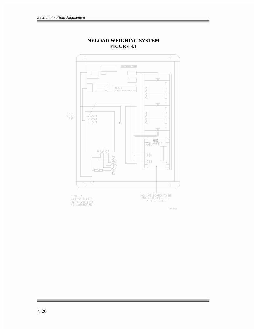
Section 4 - Final Adjustment
4-26
NYLOAD WEIGHING SYSTEMFIGURE 4.1

Section 4 - Final Adjustment
4-27
4.5.7.1.5 ADJUSTMENT - To perform the load compensation adjustments, the VVC-2-G drive unit should have been fully adjusted. It is especially important that the SPD(Speed Pick Delay) trimpot has been adjusted on the VVC-2-G drive, so that the brakeis fully lifted before motion starts, but without causing unnecessary delay in the start ofmovement. Then perform these steps. a. From the car top, first adjust the Nyload weighing system according to the
instructions provided by K-Tech. When the adjustment is done, measure thefollowing voltages between terminals LW+ and LW- on the IMC-RB-REV 1board.
Empty car (at bottom floor) 0.00VDC (+/- .2V)Balanced car (at middle floor) 4.00VDC (+/- .2V)* Full car (at top floor) 10.00VDC (+/- .4V)
* This assumes 40% counterweighing. If the counterweighing is 45%, the voltagemust be 4.50V, and so on.
b. Turn LWG trimpot (on IMC-GIO board) 25 full turns counterclockwise so that thereis no load-weigher compensation. Turn SAT trimpot fully clockwise.
c. Turn PO trimpot fully counterclockwise. Do not adjust the CMR trimpot. Thistrimpot has been set at the factory.
d. Put a balanced load in the car and place the car at the top floor. Place the voltmeterleads between test point LW and COM on the IMC-GIO board. Adjust the BALtrimpot so the voltage on LW test point is 0.00VDC.
e. Run the car down one floor and watch how it responds. If there is some rollback (orbrakeaway) with 0.00VDC on test point LW, then that would indicate that the car isnot truly balanced. To remove the rollback, carefully adjust BAL trimpot until therollback is gone.
f. Run the car one floor down from the top floor. No rollback should be observed.
g. Remove the load from the car and return the car to the top landing. Turn LWGtrimpot 25 full turns counterclockwise, and then preset it ten turns clockwise.
h. With the empty car at the top landing run the car one floor down and then up.Observe the sheave and adjust the LWG trimpot for no rollback in either direction.Now the top zone has been adjusted.
Section 4 - Final Adjustment
4-28
NOTE
If adjusting LWG makes the rollback worse, then locate jumper JP6 onthe IMC-GIO and move it to the B position. The controller is shippedwith this jumper in the A position.
i. Move the empty car to the very bottom landing. Starting with trimpot PO fullycounterclockwise, turn this trimpot clockwise in order to add enough additionalcompensation to get smooth starts while running the car one floor up and one floordown. This trimpot compensates for the position of the car in the hoistway. Theposition of the car is represented by a 0V - 10V signal available on test point TP9 onthe IMC-GIO board (APR, Analog Position Reference).
j. Now run the car from top to bottom on every floor and verify that there is norollback. Then place a full load in the car and run it to the top floor while checkingthe starts on the top floors; touch up LWG trimpot if necessary. Run the car to allfloors and observe that there is no rollback.
k. If there is a problem controlling the rollback, readjust the Rate Gain or IR COMPtrimpots on the SCR drive to allow for tighter control of the car.
4.5.7.2 ADJUSTMENT OF BRAKE TIMING CIRCUITRY - Do not perform thisadjustment if there is load compensation. This section describes the adjustment oftrimpots TB1, TB2, SPD and Brake Weakening resistor so that the brake has a highenough initial picking voltage to allow for the quick reduction of most of the braketension followed by a reduction in brake strength (initiated by potentiometer TB1 whichcontrols the pick of relay TB1). Accelerate the car out of the landing under a partiallypicked brake (acceleration initiated by SPD trimpot and the amount of weakeningadjusted by the Brake Weakening resistor). As the car begins to accelerate, continue topick the brake until the brake shoes fully clear the braking surface at which time fullbrake strength is reestablished (potentiometer TB2 initiates reapplication of full brakestrength by controlling the pick of relay TB2). The intent is to move the car severalinches as the brake is picking smoothly and to have the brake fully picked before the carmoves approximately a foot.
The following section describes adjustment of trimpots SPD, TB1 and TB2 which allowprecise coordination of brake pick and subsequent acceleration of the car away from thelanding.
a. Trimpot TB1 mounted on the backplate near timer TB1 should be adjusted so thatrelay TB1 picks as soon as approximately half the brake tension is relieved. Thebrake must not be allowed to pick fully before TB1 relay picks.

Section 4 - Final Adjustment
4-29
NOTE
If there is a current saving contact on your brake, it may interfere withthis movement. If necessary, adjust the current saving contact so that itactivates closer to the fully picked position of the brake. The intent isthat the brake is picked as fully as possible before relay TB2 picks.
b. Observe relays TB1 and TB2 and adjust trimpot TB2 as necessary to provide about1-1½ seconds from the time relay TB1 picks to the time relay TB2 picks.
c. Start with Brake Weakening resistor completely shorted. Now move the tap toweaken the brake so that a smooth and gradual movement of the brake to the fullypicked position occurs from the time TB1 picks to the time TB2 picks.
Relay TB2 guarantees a full pick of the brake at the end of this timing sequence. Ifthe brake fails to pick fully with TB2 relay picked, check the current saving brakevoltage setting to be sure it is high enough to ensure that the brake is fully released.
d. Now observe the brake operation. A smooth overall brake picking movement shouldbe present with a slight slowing of movement as relay TB1 picks. The brake shouldnot be snapping up quickly to the fully picked position.
e. Next, use trimpot SPD on the VVC-2-G drive unit to coordinate the start of motionwith the picking of the brake. Adjust SPD clockwise until rollback is observed in theup direction when the empty car is starting down from the top landing. Now turnSPD � to ¼ turns at a time counterclockwise so that the rollback is removed.
f. Observe the start of the car with the oscilloscope or chart recorder connected to testpoint T and COM on the VVC-2-G drive unit. The car should not be snapping awayfrom the floor or producing a double-humped acceleration. Ride the car and evaluatethe quality of the starts. It may be necessary to touch up trimpots BW and TB1 whichmay force recoordination of the start with the SPD trimpot as in step (e) above.
Section 4 - Final Adjustment
4-30
WARNING
This function must be successfully mastered before turning the elevatorsystem over to passenger use for normal operations.
NOTE
By now the elevator mechanic should be fully conversant with IMC-GIO diagnostics in Section 5.3 of this manual. This knowledge isessential to mastery of the learn sequence of the IMC-GIO processorboard.
NOTE
Each time the power is turned on in the elevator control system theIMC-GIO board goes through a self-test sequence which will delaystartup of the controller. Allow ten to twenty seconds for completion.
4.6 LEARNING NORMAL VELOCITY ASSOCIATED WITH EACHTERMINAL LIMIT SWITCH -
Learning the normal velocity for each Terminal switch which feeds the IMC-GIO boardis defined as recording car velocity at the time each Terminal switch is encountered ona normal approach to each terminal landing. This learn operation should be performedafter all the motion parameters have been programmed satisfactorily and all othercomponents have been fully adjusted so that the ride quality in the car is acceptable. Ifmotion parameters are altered, the speed profile changes, thus the normal velocityassociated with each Terminal switch is changed, and the IMC-GIO board learn operationmust be reinitiated. The steps for learning the normal velocities associated with eachterminal landing are as follows.
a. Verify that jumper JP3 on the IMC-GIO board has been moved to the normalposition. Turn on the Learn switch on the IMC-GIO board to permit car movementas it disables the safety cutoff function on the IMC-GIO board.
b. Make sure that all the Terminal Limit switches are properly installed. These Limitswitches may be contacts on the TM switch. The IMC-RB board has lights that verifythe Terminal Limit switch inputs to the IMC-GIO board. Toggle the Diagnostic On-

Section 4 - Final Adjustment
4-31
Normal switch on the front of the Computer Swing Panel to the Diagnostics Onposition. Dial up address 24 on the A1 to A8 switches. See Figure 5.6. This verifiesthe proper operation of the Terminal switches using the EOD. Watch the PatternGenerator Diagnostic Indicators as the car approaches each terminal landing.
As the car moves to each terminal landing verify the opening of each Terminalswitch contact by observing the corresponding LED indicator shown above. If theindicator is on it means the Terminal switch is closed, if the indicator is off it meansthe switch is open.
c. If the Learn switch is on and Alphanumeric Display indicates LRNT/LRNC then togglethe Learn switch on/off until the LRN message appears on the Alphanumeric Displayon the IMC-GIO board. The associated LED indicator on IMC-GIO lights and theAlphanumeric Display should indicate LRN.
d. Make a full hoistway run to the top terminal landing using a car call (the Test-Normswitch on the relay board should be on Test). Notice as the car starts in the updirection the Alphanumeric Display on the IMC-GIO displays LRNU. As the car stopsat the top terminal, the display reads LRN.
e. Now make a full hoistway run to the bottom terminal landing using a car call. TheAlphanumeric Display reads LRND at this time. When the car stops at the bottomterminal landing, the IMC-GIO goes through a sequence of operation to write thelearned data into the non-volatile memory (EEPROM). The IMC-GIO then reads thedata from the non-volatile memory for verification. Once the data have beensuccessfully stored into the non-volatile memory (EEPROM) the IMC-GIO displaysa Learn Complete message LRNC. The data-storing sequence is displayed on theAlphanumeric Display with LRNW indicating that the IMC-GIO is writing the learneddata into the EEPROM. LRNR indicates that the IMC-GIO is reading the stored databack for verification and LRNC indicates that the IMC-GIO learn operation iscomplete. Move the JP3 jumper back to the Normal position.
f. Turn off the Learn switch on the IMC-GIO board. The display indicates the lastleveling speed encountered. The IMC-GIO board has now learned the normal speedof the car as the Terminal switches are encountered on an approach to each terminallanding. This provides independent overspeed safety monitoring for the terminallandings. The IMC-GIO Alphanumeric Display displays the car speed as it moves orit displays error conditions that exist. For detailed information on the IMC-GIOdiagnostics, refer to Section 5.3.
g. Verify the Limit switch velocity values stored during normal slowdown at theterminal landings by depressing the Computer Reset button on the upper edge of theIMC-GIO board and releasing it. As the Computer Reset button is released, the IMC-GIO performs a self-test, followed by the display of each Limit switch input name

80fpmContractVelocity
Section 4 - Final Adjustment
4-32
and the pertinent learned velocity. Each value must be less than 95% of the contractvelocity.
h. Verify that proper safety protection exists at the terminal landing, as provided by theIMC-GIO board. Disconnect each Terminal Limit switch input feeding this boardwhile the car runs at contract speed. The number of Limit switch inputs varyaccording to the car speed. Refer to the Limit Input Terminals designated ULS1through ULS4 and DLS1 through DLS4. If terminals ULS1 or DLS1 cannot befound, they may be connected with terminals 28X and 29X. Refer to pages 2 and 6of the job prints in Section 7. For each terminal with a ULS prefix run the car up atcontract speed and remove each wire from the terminal. In each case, the car mustdecelerate rapidly to a special leveling speed determined by the Safety Voltagetrimpot, located on the upper corner of the IMC-GIO board. Adjust this trimpot togive the same value as the programmed Leveling Velocity. After the car comes to astop, insert the wires into the terminals. Do the same for each terminal with a DLSprefix. Run the car down at contract speed and remove each wire from the terminal.Again, in each case, the car must decelerate rapidly to leveling speed. Adjust theACC trimpot on the drive unit to give a very rapid deceleration rate under thiscondition, but avoid violent acceleration or deceleration. The acceleration rate settingon trimpot ACC should be high enough to exceed any programmed acceleration ordeceleration rate. It should also have sufficiently rapid deceleration to stop the carsafely, in case one of the safety functions in the IMC-GIO processor board detectsinsufficient deceleration at a terminal landing, or if the IMC-DDP detects otherproblems such as loss of position pulser signals, etc. After the car comes to a stop,insert the wires into the terminals. Every time the safety processor detects anoverspeed at the terminal landing, a Terminal Slowdown event is logged into theEvent Calendar under normal operation.
i. When a Terminal Slowdown is logged due to overspeed at a terminal landing afterthe car has slowed down, an alternate pattern is provided to move the car to the floorin order to prevent the car's getting stuck between floors. The value of the alternatepattern is adjusted by the trimpot Safety Voltage Adj located above theAlphanumeric Display next to the JP3 jumper on IMC-GIO board. Adjust thistrimpot so the alternate pattern is about 6 to 8 fpm. To do so, connect one lead of thevoltmeter to test point COM and the other lead to test point Safety Patt. A voltageequal to that calculated by the following equation, for an emergency speed of 8 fpm,should be measured with the equation below. This trimpot is usually adjusted at thefactory before the controller is shipped.
j. The drive adjustment is now complete. Remove all jumpers, finish other adjustments(doors, etc.) and test all safety items and door locks. The performance of the elevatorsystem depends on the proper adjustment of the drive and the use of all its features.
Section 4 - Final Adjustment
4-33
WARNING
The following tests should be performed only by qualified elevatorpersonnel, skilled in final adjustments and inspections.
NOTE
The motor field voltage should be recorded during contract speed, so itcan be returned to this value after the tests, if necessary.
4.7 PROCEDURES FOR PERFORMING THE FINALACCEPTANCE TESTS -
4.7.1 CONTRACT SPEED BUFFER TESTS -
a. Car Buffer Test with Full Load Going Down - To complete a full load car buffer testgoing down, a number of functions must be bypassed using jumpers as follows.
1. Connect a jumper between terminals 20X and 21X on the VVC-2-G drive unitterminal strip, which bypasses the safety functions.
2. Remove jumper plug on JP3 from location Norm to location TFB on the IMC-GIO board. This is to bypass the IMC-GIO safety functions.
3. Bypass the Down Normal Limit by connecting a jumper from terminals 8 to 12.
Place the elevator several floors above the bottom. Turn on the Relay PanelInspection switch and move the jumper plug from JP5 to JP4 on the IMC-GIO board.The speed signal is now the single turn Pattern Adj trimpot on the IMC-GIO board.This should be set fully counterclockwise to start. Remember that a full clockwisesetting overspeeds the car. Therefore, have a second person call out the car speed asthe car is operated on inspection down and turn the trimpot quickly to at least thehalfway point. Continue more slowly clockwise until contract speed is reached. Thecar will strike the buffer. Turn the Pattern Adj trimpot fully counterclockwise, thenvery slightly clockwise to provide a slow speed for moving the car away from thebuffer. Remove the jumper from terminals 8 to 12. Temporarily connect a jumper to
Section 4 - Final Adjustment
4-34
terminals 2 and 16 to move the car off the fully compressed buffer. Leave the otherjumpers in place to perform the next test for the counterweight buffer. If this is thelast test to be performed, go to step 4.7.3 below; otherwise, continue.
b. Counterweight Buffer Test with Empty Car Going Up - Steps (a) 1 and 2 should becompleted. Connect a jumper from terminal 8 to 10 to bypass the Up Normal Limitswitch. The car should be on Relay Panel Inspection operation with the Pattern Adjtrimpot fully counterclockwise. The jumper plug on the IMC-GIO board should bein the JP4 position. Have a second person call out the car speed as the car is operatedon inspection up and turn the trimpot quickly to at least the halfway point, thencontinue more slowly clockwise until contract speed is reached. The counterweightwill then strike the buffer. Turn the Pattern Adj trimpot fully counterclockwise, thenvery slightly clockwise, to provide a slow speed for moving the counterweight awayfrom the buffer. Remove the jumper from terminals 8 to 10. Temporarily connect ajumper to terminals 2 and 16 to move the counterweight off the fully compressedbuffer. Leave the other jumpers in place to perform the next tests for the governor.If this is the last test to be performed, go to step 4.7.3 below; otherwise, continue.
4.7.2 GOVERNOR TESTS -
a. Governor Electrical Overspeed Switch Test - Trip open the Electrical Overspeedswitch contact manually to verify that the main safety circuit drops out. Use the mostconvenient method to verify the actual electrical and mechanical tripping speeds. Forexample, use a drill motor to spin the governor with the governor cable lifted off thegovernor. Replace the governor cable.
b. Governor and Car Safety Overspeed Test with Full Load Going Down - Completestep 4.7.1.a.2 above. Bypass the Electrical Overspeed switch on the governor byconnecting a jumper from terminals 2 to 16. Bypass the Car Safety switch on the carby connecting a jumper to terminals 16 and 18. Turn the Pattern Adj trimpot fullycounterclockwise. Use the Relay Panel Inspection switches and Pattern Adj trimpotto move the car to the top of the hoistway in preparation for overspeeding the car inthe down direction. The car should be fully loaded before starting the test. Tocomplete this test, run the car down with the Relay Panel Inspection switch, whileadvancing the Pattern Adj trimpot quickly to just below contract speed, then moreslowly clockwise to the point where the car safety sets. Stop only after the safety isfirmly set, which is indicated by the drive sheave slipping under the hoist ropes.
Check the hoist ropes to make sure they are still in their proper grooves beforeattempting to move the car. Reset the governor jaws and the governor Overspeedswitch. Remove the jumper between terminals 2 and 16. With flexible guideclamp safeties, move the car on inspection in the up direction to release thesafeties. With wedge clamp safeties, release the safeties from inside the car. Oncethe safeties have been released, remove the jumper between terminals 16 and 18.
Section 4 - Final Adjustment
4-35
NOTE
If counterweight safety and governor are present, reverse directions fortesting.
Move the car down on inspection to make sure the safety has completely releasedand returned to the normal position.
c. At the end of all buffer and governor safety tests, verify that there are no jumpersbetween terminals 2 to 16, 16 to 18, 8 to 10, and 8 to 12. Remove the jumper plugon JP3 from TFB position and place it in the Norm position on the IMC-GIO board.If steps 4.7.3, 4.7.4 and 4.7.5 are not to be completed, remove the jumper onterminals 20X and 21X on the VVC-2-G drive unit terminal strip, and turn off theRelay Panel Inspection switch to restore normal operation. Remove jumper plugfrom location JP4 and place it on position JP5. If the Pattern Adj trimpot is turnedfully clockwise the car should reach contract speed during normal operation.
4.7.3 INSPECTION/LEVELING 150 FPM OVERSPEED TEST - For this test,refer to Section 4.5.6.a.
4.7.4 EMERGENCY TERMINAL SPEED LIMITING DEVICE TEST - For this
test, refer to Section 4.5.6.b.5.
4.7.5 TERMINAL SLOWDOWN LIMIT SWITCHES - There are three ways toaccomplish this test.
a. For this test, refer to Section 4.6.h.
b. An alternative method to run this test is to place the car in the middle of thehoistway, remove the jumper from JP5 and place it into JP4 on the IMC-GIO board.Turn the Pattern Adj trimpot fully counterclockwise. Place the car on inspection andrun the car down, while turning the Pattern Adj trimpot clockwise until contractspeed is reached. Let the car go through the bottom terminal and observe that theTerminal Slowdown switches slow down the car. Note that the pattern output mustbe routed through the safety cutoff relay on IMC-GIO board for this test to work. Thejumper plug on JP3 shall be in the Norm position. The same test may be performedfor the up direction by running the car up on inspection. Remember the decelerationrate is determined by the ACC trimpot on the VVC-2-G drive unit, so if the car goesonto the buffer the ACC may have to be turned further in the clockwise direction.
Section 4 - Final Adjustment
4-36
WARNING
Before the elevator is turned over to normal use, verify that no safetycircuit has been bypassed. Use the list below as a partial checklist.
- No jumpers on terminals 4 and 8 (HC-RB)- No jumpers on terminals 2 and 16 (HC-RB)- No jumpers on terminals 16 and 18 (HC-RB)- No jumpers on terminals 8 and 10 (HC-RB)- No jumpers on terminals 8 and 12 (HC-RB)- Level Down LD installed on terminal 25 (HC-RB)- No jumper on JP4 (IMC-GIO) - Jumper plug on JP5 must be installed (IMC-GIO)- Jumper on JP3 must be in position NORM (IMC-GIO)- Pattern Adj trimpot must be fully clockwise (IMC-GIO)- No jumpers on terminals 20X and 21X (Drive unit)- No jumpers on R0 - R6 and PR terminals (IMC-RB)- No jumpers on JP1/INTB on IMC-RB
c. A third method to run this test is to place the car at a lower floor (second or thirdfloor), then connect a jumper from 120VAC to the respective PR, R0, R1-R5, tomake the controller think it is at a higher floor. Then place a call to the bottom floorand let the car go through the bottom terminal. Verify that the Terminal Slowdownswitches slow down the car. The pattern output must be routed through the IMC-GIOboard for this test to work. Following is an example of how this test may beperformed.
1. Place the car at the second floor.
2. Jumper 120VAC or the 2 bus to R0 and R2 (this would make the controller thinkthe car is at seventh floor).
3. Place a car call to the bottom landing.
Test the Upper Terminal Limit by using the same method described above. Only thistime, place the car at a floor close to the top, making the controller think it is actuallyat a lower floor by manipulating the PR, R0 - R5. Then run the car up to the upperterminal floor and observe that the Terminal Slowdown switches would slow downthe car. If the car lands on the buffer, turn the ACC trimpot clockwise on the VVC-2-G drive unit.
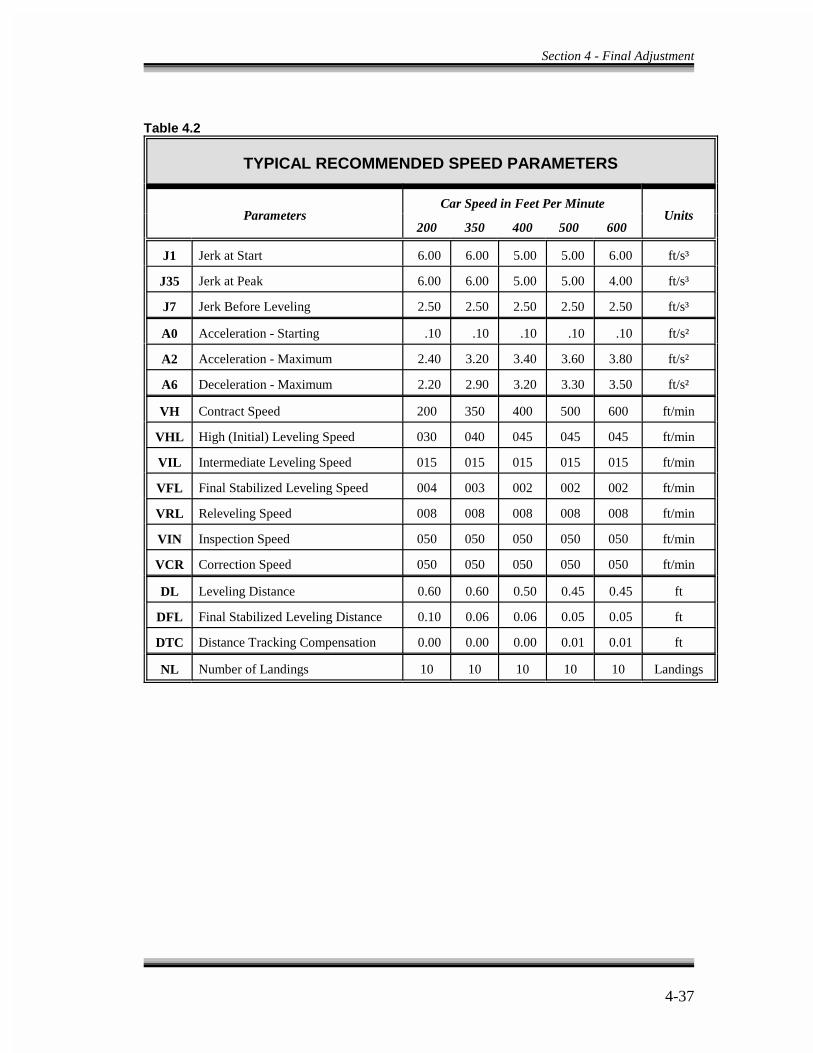
Section 4 - Final Adjustment
4-37
Table 4.2
TYPICAL RECOMMENDED SPEED PARAMETERS
Parameters UnitsCar Speed in Feet Per Minute
200 350 400 500 600
J1 Jerk at Start 6.00 6.00 5.00 5.00 6.00 ft/s³
J35 Jerk at Peak 6.00 6.00 5.00 5.00 4.00 ft/s³
J7 Jerk Before Leveling 2.50 2.50 2.50 2.50 2.50 ft/s³
A0 Acceleration - Starting .10 .10 .10 .10 .10 ft/s²
A2 Acceleration - Maximum 2.40 3.20 3.40 3.60 3.80 ft/s²
A6 Deceleration - Maximum 2.20 2.90 3.20 3.30 3.50 ft/s²
VH Contract Speed 200 350 400 500 600 ft/min
VHL High (Initial) Leveling Speed 030 040 045 045 045 ft/min
VIL Intermediate Leveling Speed 015 015 015 015 015 ft/min
VFL Final Stabilized Leveling Speed 004 003 002 002 002 ft/min
VRL Releveling Speed 008 008 008 008 008 ft/min
VIN Inspection Speed 050 050 050 050 050 ft/min
VCR Correction Speed 050 050 050 050 050 ft/min
DL Leveling Distance 0.60 0.60 0.50 0.45 0.45 ft
DFL Final Stabilized Leveling Distance 0.10 0.06 0.06 0.05 0.05 ft
DTC Distance Tracking Compensation 0.00 0.00 0.00 0.01 0.01 ft
NL Number of Landings 10 10 10 10 10 Landings
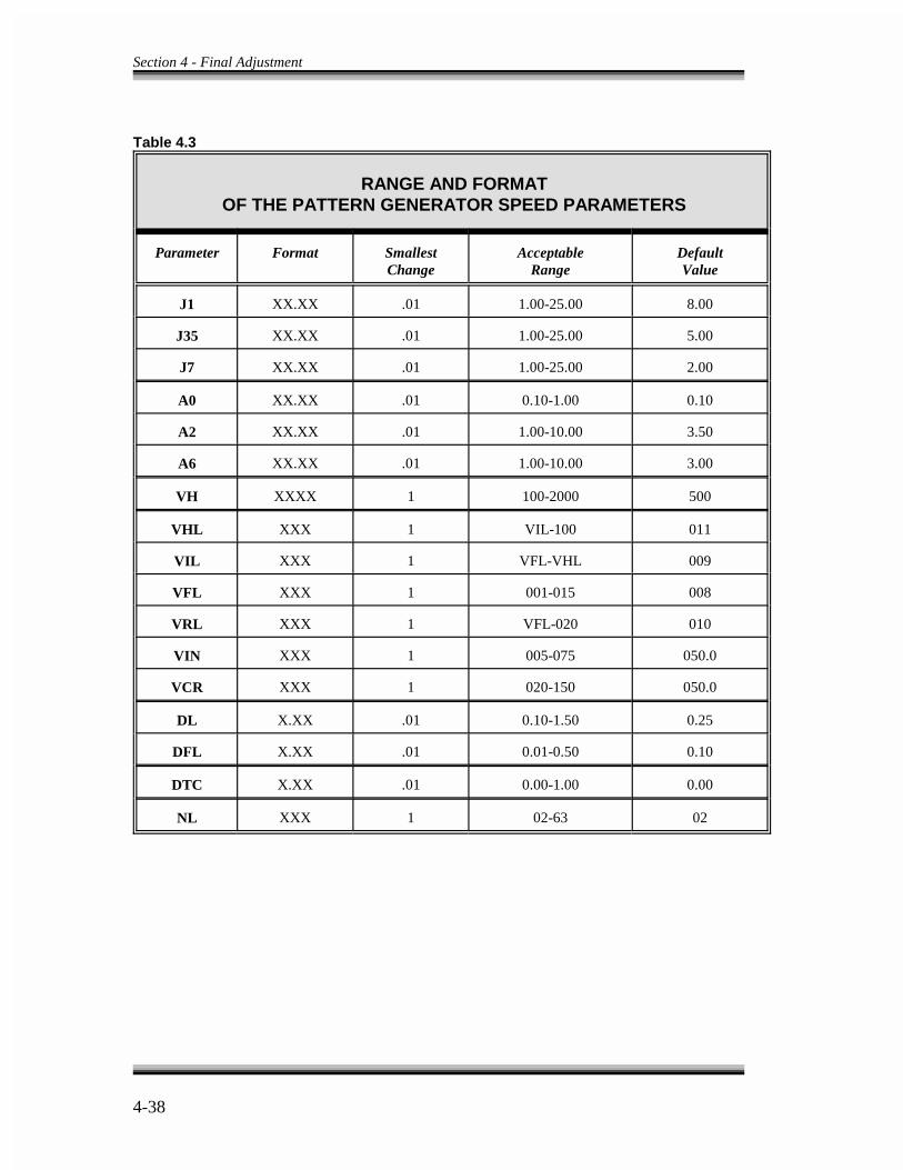
Section 4 - Final Adjustment
4-38
Table 4.3
RANGE AND FORMATOF THE PATTERN GENERATOR SPEED PARAMETERS
Parameter Format Smallest Acceptable DefaultChange Range Value
J1 XX.XX .01 1.00-25.00 8.00
J35 XX.XX .01 1.00-25.00 5.00
J7 XX.XX .01 1.00-25.00 2.00
A0 XX.XX .01 0.10-1.00 0.10
A2 XX.XX .01 1.00-10.00 3.50
A6 XX.XX .01 1.00-10.00 3.00
VH XXXX 1 100-2000 500
VHL XXX 1 VIL-100 011
VIL XXX 1 VFL-VHL 009
VFL XXX 1 001-015 008
VRL XXX 1 VFL-020 010
VIN XXX 1 005-075 050.0
VCR XXX 1 020-150 050.0
DL X.XX .01 0.10-1.50 0.25
DFL X.XX .01 0.01-0.50 0.10
DTC X.XX .01 0.00-1.00 0.00
NL XXX 1 02-63 02
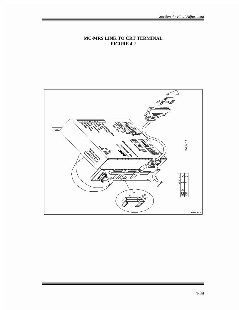
Section 4 - Final Adjustment
4-39
MC-MRS LINK TO CRT TERMINALFIGURE 4.2
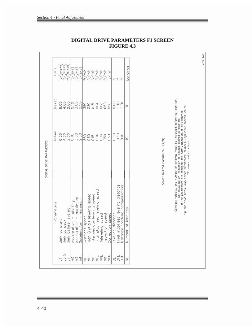
Section 4 - Final Adjustment
4-40
DIGITAL DRIVE PARAMETERS F1 SCREENFIGURE 4.3
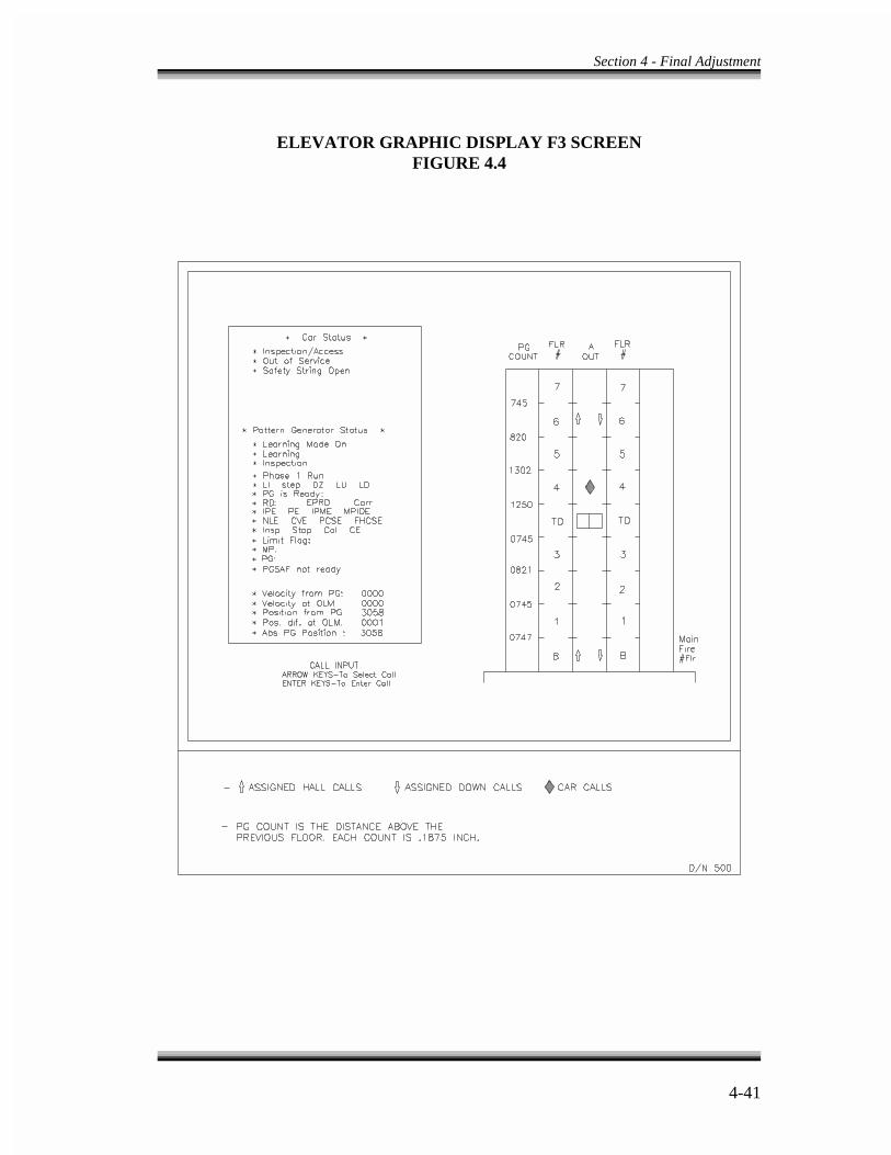
Section 4 - Final Adjustment
4-41
ELEVATOR GRAPHIC DISPLAY F3 SCREENFIGURE 4.4
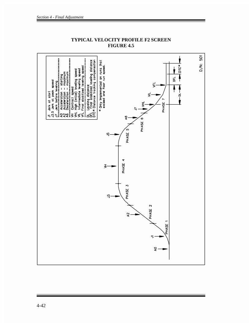
Section 4 - Final Adjustment
4-42
TYPICAL VELOCITY PROFILE F2 SCREENFIGURE 4.5
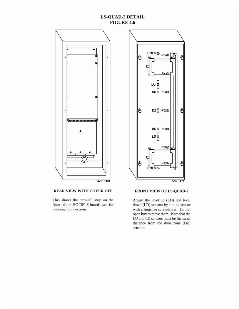
LS-QUAD-2 DETAILFIGURE 4.6
FRONT VIEW OF LS-QUAD-2
Adjust the level up (LD) and leveldown (LD) sensors by sliding sensorwith a finger or screwdriver. Do notopen box to move them. Note that theLU and LD sensors must be the samedistance from the door zone (DZ)sensors.
REAR VIEW WITH COVER OFF
This shows the terminal strip on thefront of the HC-DFLS board used forcustomer connections.

5-1
SECTION - 5
HUMAN INTERFACE
5.0 GENERAL INFORMATION -
Since the VVMC-1000 Series Turbo DF traction controller employs more than oneprocessor, it requires a user-friendly, comprehensive and elaborate diagnostic tool whichwill help the elevator mechanic install, adjust, service and troubleshoot the equipment.The diagnostic tools available to the Series Turbo DF controllers are listed here.
- CRT terminal, with user-friendly menus- Enhanced On-Board Diagnostics (EOD)- IMC-GIO On-Board Diagnostics
5.1 CRT TERMINAL -
The CRT terminal provides the elevator mechanic with a set of easy to use menus for thepurpose of adjusting, servicing and troubleshooting the controller. To install the CRT,see MCE Computer Peripherals Manual. The CRT is only needed for adjustment of thedrive parameters and for viewing the Event Calendar (fault history). Information fortroubleshooting and diagnostics is available through both the EOD and the CRT.
5.2 ENHANCED ON-BOARD DIAGNOSTICS (EOD) -
5.2.0 GENERAL INFORMATION - This controller is self sufficient in that it does notrequire external devices to view the necessary flags inside the computer. For a completelisting of these flags, see Table 5.3. The EOD was designed to help the elevator mechanicdetermine what the elevator control system is actually trying to do, or what it isperceiving. It also enables the mechanic to adjust specific system parameters (e.g., doortimes). The EOD is a powerful tool to use for troubleshooting the control system. Forexample, even though the signal from a switch might exist on the proper terminal in thecontroller, the elevator system may not respond to it. That is to say, it is possible for thecontroller not to respond, even though it is operating correctly. The mechanic mustdetermine, through the EOD, why this has occurred. The computer is the most reliablecomponent in the control system and the EOD points the way to the real source of theproblem whether inside or outside the controller.
Since the speed pattern for the motion of the elevator (in the Series Turbo DF tractioncontroller) is generated by the IMC-DDP computer board, the Enhanced On-BoardDiagnostics encompasses the diagnostics of the IMC-DDP, as well.

Section 5 - Human Interface
5-2
NOTE
Pressing the reset button drops the safety relay and causes immediatestopping of the elevator.
The Enhanced On-Board Diagnostics (EOD) operates in three separate modes. They arenormal, diagnostic and system mode. All three modes are discussed in detail in thissection.
5.2.1 FUNCTIONAL DESCRIPTION OF INDICATORS AND SWITCHES OFEOD -The diagnostic indicators and switches are located on the front, top and backsection of the Swing Panel. Figures 5.1, 5.2 and 5.3 show the indicators and switches onthe Computer Swing Panel. Following is a brief functional description of these indicatorsand switches.
a. Computer on Indicator Light (located on the front of the Swing Panel, Figure 5.1) -The Computer On light indicates that the MC-MP computer is functioning normallyand is completing its program loop successfully. Resetting the microcomputer turnsthis light off and it remains off while the reset button is depressed. The ComputerOn light turns back on when the reset button is released. The microcomputer isequipped with an auto reset feature that causes the elevator to go through a resettingprocess if, for any reason, the program loop can not be completed (for example, avery strong electromagnetic or line noise may cause computer malfunctioning). Thecomputer automatically resets itself and goes back to normal operation. Thisprevents unnecessary trouble calls if the transient has not caused any hardwaredamage. The auto reset process also causes the Computer On light to turn off forbrief periods. If the Computer On light flashes on/off, it means the program is notlooping successfully and the processor board is malfunctioning. Check the EPROMchip to verify proper installation. See Appendix C in this manual.
b. Group of Eight Vertical Status Indicators (located on the front of the Swing Panel)- When these lights are on, each one has a meaning. These lights indicate theimportant elevator statuses in the following order.
1. Safety circuit is closed (top light).2. Door lock contacts are closed.3. Elevator is running high speed.4. Elevator is on independent service.5. Elevator is on car top inspection or hoistway access operation.

Section 5 - Human Interface
5-3
6. Elevator is on fire service operation.7. Elevator is timed out of service.8. Motor limit timer has elapsed (bottom light).
c. Diagnostic Indicators (Located on the front of the Swing Panel - Figure 5.1) Theeight horizontal diagnostic indicator lights (MP diagnostic indicators) have twofunctions. When on diagnostic on, they indicate the contents of computer memoryand when in normal mode, they indicate the prevailing status or error message.
d. Alphanumeric Display (Located on the front of the Swing Panel - Figure 5.1) -Theeight character Alphanumeric Display provides more user-friendly interactionbetween the control equipment and the elevator mechanic by displaying messagesin English text or abbreviations.
e. Computer Reset Pushbutton (Located on the upper left hand corner on the front ofthe Computer Swing Panel - Figure 5.1) - Pressing the reset button causes the MC-MP (main processor) and the MC-CP (communication processor) computer boardsto reset. This drops the safety relay and brings the elevator to an immediate stop ifthe elevator is running. The elevator then goes to the closest floor to correct itsposition before responding to any calls. Existing call and PI information are losteach time the microcomputer is reset.
f. The Eight Lower Address Switches (Located on the front of the Swing Panel -Figure 5.1) - These are labeled A1 through A8 from right to left. These switchesenable the elevator mechanic to look at the memory on the processor board. Theseswitches are on in the up position and off in the down position.
g. Car A/Car B (F1) Switch (Located on the front of the Swing Panel Figure 5.1) -Thisswitch, in a duplex configuration, indicates which car's information is beingdisplayed and which car's data can be addressed by the A1-A8 switches. If theelevator system is a simplex, always place this switch in the up position for Car A.
h. Diagnostics On-Normal Switch (Located on the front of the Swing Panel - Figure5.1) - This switch puts the system in diagnostic mode in the up position and innormal mode in the down position.
i. Function Switches F2-F7 (Located on the front of the Swing Panel - Figure 5.1) -These six switches act as function switches to put the EOD in different modes ofoperation. The three modes of operation are discussed in detail in this section of themanual.

Section 5 - Human Interface
5-4
j. Two Pushbutton Switches Marked N and S (Located on the front of the Swing Panel- Figure 5.1) - These pushbuttons are used in the different diagnostic modes toscroll through a list of data.
k. Six Higher Address Switches (Located on the front of the Swing Panel - Figure 5.1)- A9 through A14 from right to left. These address switches are primarily used bythe factory.
l. Pattern Generator Diagnostic Indicators (Located on the top of the Swing Panel-Figure 5.2) - The eight Pattern Generator Diagnostic Indicators have two functions.When in diagnostic mode, they indicate the contents of pattern generator computermemory, and when in normal mode they indicate the prevailing status or errormessage related to the IMC-DDP processor board.
m. DDP Computer On Indicator Light (Located on the back of the Swing Panel -Figure 5.3) - The Computer On light indicates that the IMC-DDP board isfunctioning normally and is completing its program loop successfully. Resettingthis computer turns this light off and it remains off while the reset button isdepressed. The Computer On light turns back on when the reset button is released.
The IMC-DDP computer board is equipped with an auto reset feature that causesthe IMC-DDP computer to go through a resetting process if for any reason theprogram loop cannot be completed. Using the reset button prevents unnecessarytrouble calls if the accident has not caused any hardware damage. The auto resetprocess also causes the DDP Computer On light to turn off for a brief period. If theDDP Computer On light flashes on/off, it means that the program is not loopingsuccessfully and the processor board is malfunctioning. Check the EPROM chip tomake sure it is installed properly (see Appendix C).
n. CP Computer On Indicator Light (Located on the back of the Swing Panel - Figure5.3) - The Computer On light indicates that the MC-CP computer is functioningnormally and is completing its program loop successfully. The MC-CP computeris equipped with an auto reset feature that causes the elevator to go through aresetting process if for any reason the program loop cannot be completed.
o. DDP Computer Reset Pushbutton (Located on the back of the Swing Panel - Figure5.3) - Pressing the reset button causes the IMC-DDP processor board to reset. Itdrops the speed pattern to zero and the elevator rapidly drops its velocity to zero.
5.2.2 NORMAL MODE OF OPERATION - Normal mode is selected by moving theDiagnostic On-Normal switch to the off/down position. Make sure that the F7 switch is

Section 5 - Human Interface
5-5
also in the off/down position. See Figure 5.1. Below is a brief description of the functionof the indicators and switches used in this mode.
a. Group of Eight Vertical Lights used as the elevator status indicators as defined onSection 5.2.1 (b).
b. Diagnostic Indicators on the front of the Swing Panel scan normal from right to leftor indicate an error or other status that the microcomputer recognizes to be theprevailing status dominating the elevator function. (If the car is slaved to the groupsupervisor in a multi-car group system, the lights scan from right to left then left toright.) When troubleshooting, pay special attention to these indicators. They signalexactly what is wrong with the elevator system or act as a guide to the source of theproblem. See Table 5.8. The error status messages are in order of priority. Forexample, if the car is on independent service and the safety string is open, theindicators show that the safety string is open. Once the safety string is made, theindicators shows the car is on independent service.
c. Pattern Generator Diagnostic Indicators scan normal from right to left or indicatean error or other status that the IMC-DDP computer recognizes as the prevailingstatus dominating the pattern generator function. When troubleshooting, pay specialattention to these indicators. See Table 5.8 for the LED representations.
d. F1 (CAR A/B), F2, F3, F4, F5 and F6 Function Switches - Each of the F switches(F1 - F6) performs a special function in this mode. In normal mode the F7 switchmust be in the off or down position. If more than one of these switches are on at thesame time, the Alphanumeric Display reads PLEASE SELECT ONLY ONE FUNCTION.
If all F function switches (F1 - F7) are in the off/down position, the AlphanumericDisplay would show the military time in hours, minutes and seconds. If F3 or F6is turned on, the Alphanumeric Display would show the time.
5.2.2.1 ADJUSTMENT OF THE ELEVATOR TIMERS - To view or adjust theelevator timing functions, the F2 Switch (in normal mode), should be in the on/upposition. The F2 function displays the value of the programmable timers (e.g., doortimes, etc.) and allows the user to change these values. In the case of a duplex system,Car A and Car B values are the same and the Car A/Car B switch does not have anyeffect on this function.
When the F2 switch is turned on, the Alphanumeric Display would show CCT 01S. Thefirst word (CCT) is the flag for car call time. The number (01S) shows that the car call timehas been set for 01 second. If the value is in minutes, the last letter displayed would beM instead of S. Table 5.6 shows the list of all the adjustable timers and their adjustmentranges.
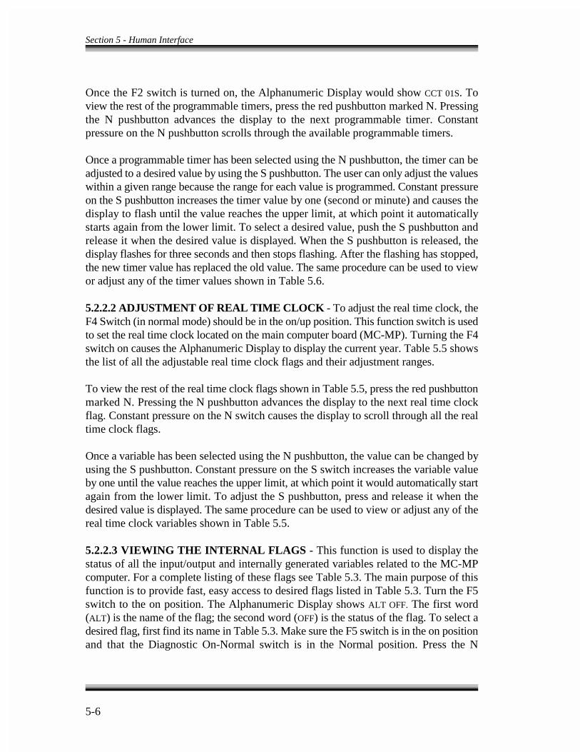
Section 5 - Human Interface
5-6
Once the F2 switch is turned on, the Alphanumeric Display would show CCT 01S. Toview the rest of the programmable timers, press the red pushbutton marked N. Pressingthe N pushbutton advances the display to the next programmable timer. Constantpressure on the N pushbutton scrolls through the available programmable timers.
Once a programmable timer has been selected using the N pushbutton, the timer can beadjusted to a desired value by using the S pushbutton. The user can only adjust the valueswithin a given range because the range for each value is programmed. Constant pressureon the S pushbutton increases the timer value by one (second or minute) and causes thedisplay to flash until the value reaches the upper limit, at which point it automaticallystarts again from the lower limit. To select a desired value, push the S pushbutton andrelease it when the desired value is displayed. When the S pushbutton is released, thedisplay flashes for three seconds and then stops flashing. After the flashing has stopped,the new timer value has replaced the old value. The same procedure can be used to viewor adjust any of the timer values shown in Table 5.6.
5.2.2.2 ADJUSTMENT OF REAL TIME CLOCK - To adjust the real time clock, theF4 Switch (in normal mode) should be in the on/up position. This function switch is usedto set the real time clock located on the main computer board (MC-MP). Turning the F4switch on causes the Alphanumeric Display to display the current year. Table 5.5 showsthe list of all the adjustable real time clock flags and their adjustment ranges.
To view the rest of the real time clock flags shown in Table 5.5, press the red pushbuttonmarked N. Pressing the N pushbutton advances the display to the next real time clockflag. Constant pressure on the N switch causes the display to scroll through all the realtime clock flags.
Once a variable has been selected using the N pushbutton, the value can be changed byusing the S pushbutton. Constant pressure on the S switch increases the variable valueby one until the value reaches the upper limit, at which point it would automatically startagain from the lower limit. To adjust the S pushbutton, press and release it when thedesired value is displayed. The same procedure can be used to view or adjust any of thereal time clock variables shown in Table 5.5.
5.2.2.3 VIEWING THE INTERNAL FLAGS - This function is used to display thestatus of all the input/output and internally generated variables related to the MC-MPcomputer. For a complete listing of these flags see Table 5.3. The main purpose of thisfunction is to provide fast, easy access to desired flags listed in Table 5.3. Turn the F5switch to the on position. The Alphanumeric Display shows ALT OFF. The first word(ALT) is the name of the flag; the second word (OFF) is the status of the flag. To select adesired flag, first find its name in Table 5.3. Make sure the F5 switch is in the on positionand that the Diagnostic On-Normal switch is in the Normal position. Press the N

Section 5 - Human Interface
5-7
pushbutton until the first letter of the flag displayed is the same as the first letter of theflag selected. Now release the N switch and press the S switch to scroll through the listof flags beginning with that letter.
5.2.3 DIAGNOSTIC MODE OF OPERATION - Diagnostic mode is selected bytoggling the Diagnostic On-Normal switch to the on/up position, making sure that the F7switch is in the off/down position. See Figure 5.1.
a. Group of Eight Vertical Lights are used as the elevator status indicators, as definedin Section 5.2.1 (b).
b. Diagnostic Indicators on the front of the Computer Swing Panel are used in
conjunction with the function switches (F1-F7). Therefore, depending on theselected function, they display different information.
c. Pattern Generator Diagnostic Indicators are used in conjunction with the functionswitches (F1-F7). Therefore, depending on the selected function, they displaydifferent information.
d. F1 (CAR A/B), F2, F3, F4, F5, F6 Function Switches - Each of the F switches (F1-F6) performs a special function in this mode. In diagnostics mode the F7 switchmust be in the off/down position. If more than one of these switches is on at thesame time, the Alphanumeric Display reads PLEASE SELECT ONLY ONE FUNCTION.
If all F function switches (F2-F7) are in the off/down position, the AlphanumericDisplay reads ADD. /0 /0H.
5.2.3.1 VIEWING THE MC-MP AND IMC-DDP COMPUTER MEMORY FLAGS-If none of the F1-F7 switches are on, the A1-A8 switches make it possible to view theMC-MP and IMC-DDP computer memory flags. Figures 5.4, 5.5 and 5.6 show theaddress and location of all flags needed for troubleshooting the system. Table 5.3 listseach variable or flag related to the MC-MP computer with a brief functional description.Table 5.4 lists each variable or flag related to IMC-DDP with a brief functionaldescription.
Once an address has been selected on the A1-A8 switches, the Alphanumeric Displayshows the address (e.g., ADD.22H which means address line 22).
There is an alternate way to look at the memory without using the A1-A8 switches. Touse this method, regardless of the position of A1-A8 switches, press the N pushbutton.The Alphanumeric Display shows ADD.20H and the MP diagnostic indicators signal thecontents of the address displayed. Keeping the N pushbutton down increases the addressshown on the Alphanumeric Display and the eight indicator lights change respectively.
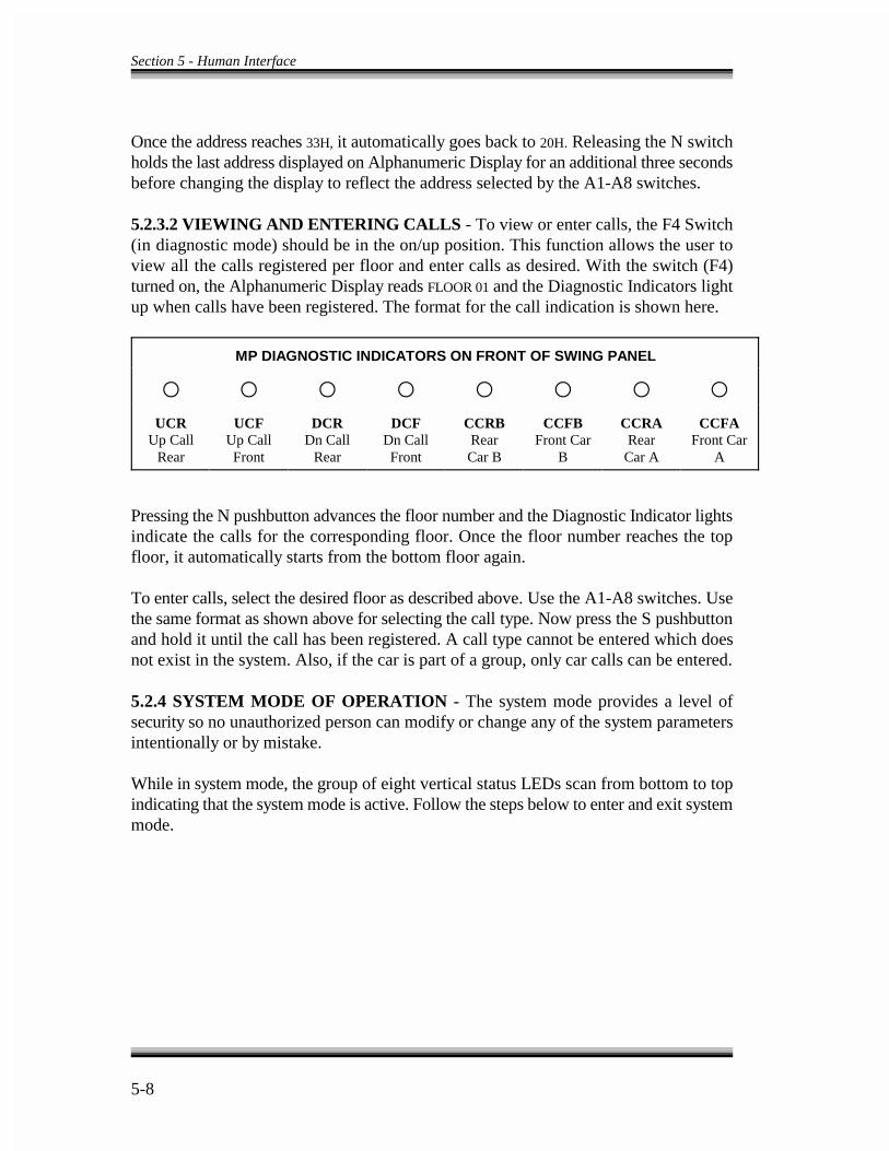
Section 5 - Human Interface
5-8
Once the address reaches 33H, it automatically goes back to 20H. Releasing the N switchholds the last address displayed on Alphanumeric Display for an additional three secondsbefore changing the display to reflect the address selected by the A1-A8 switches.
5.2.3.2 VIEWING AND ENTERING CALLS - To view or enter calls, the F4 Switch(in diagnostic mode) should be in the on/up position. This function allows the user toview all the calls registered per floor and enter calls as desired. With the switch (F4)turned on, the Alphanumeric Display reads FLOOR 01 and the Diagnostic Indicators lightup when calls have been registered. The format for the call indication is shown here.
MP DIAGNOSTIC INDICATORS ON FRONT OF SWING PANEL
� � � � � � � �
UCR UCF DCR DCF CCRB CCFB CCRA CCFAUp Call Up Call Dn Call Dn Call Rear Front Car Rear Front Car
Rear Front Rear Front Car B B Car A A
Pressing the N pushbutton advances the floor number and the Diagnostic Indicator lightsindicate the calls for the corresponding floor. Once the floor number reaches the topfloor, it automatically starts from the bottom floor again.
To enter calls, select the desired floor as described above. Use the A1-A8 switches. Usethe same format as shown above for selecting the call type. Now press the S pushbuttonand hold it until the call has been registered. A call type cannot be entered which doesnot exist in the system. Also, if the car is part of a group, only car calls can be entered.
5.2.4 SYSTEM MODE OF OPERATION - The system mode provides a level ofsecurity so no unauthorized person can modify or change any of the system parametersintentionally or by mistake.
While in system mode, the group of eight vertical status LEDs scan from bottom to topindicating that the system mode is active. Follow the steps below to enter and exit systemmode.
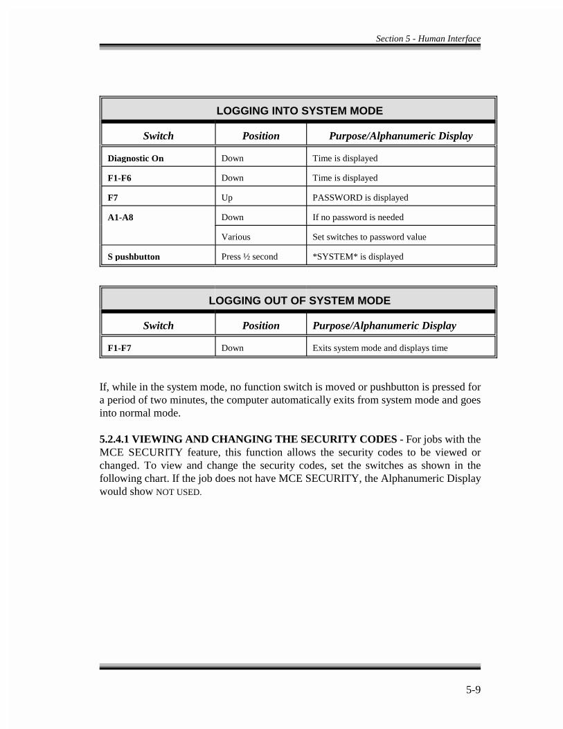
Section 5 - Human Interface
5-9
LOGGING INTO SYSTEM MODE
Switch Position Purpose/Alphanumeric Display
Diagnostic On Down Time is displayed
F1-F6 Down Time is displayed
F7 Up PASSWORD is displayed
A1-A8 Down If no password is needed
Various Set switches to password value
S pushbutton Press ½ second *SYSTEM* is displayed
LOGGING OUT OF SYSTEM MODE
Switch Position Purpose/Alphanumeric Display
F1-F7 Down Exits system mode and displays time
If, while in the system mode, no function switch is moved or pushbutton is pressed fora period of two minutes, the computer automatically exits from system mode and goesinto normal mode.
5.2.4.1 VIEWING AND CHANGING THE SECURITY CODES - For jobs with theMCE SECURITY feature, this function allows the security codes to be viewed orchanged. To view and change the security codes, set the switches as shown in thefollowing chart. If the job does not have MCE SECURITY, the Alphanumeric Displaywould show NOT USED.
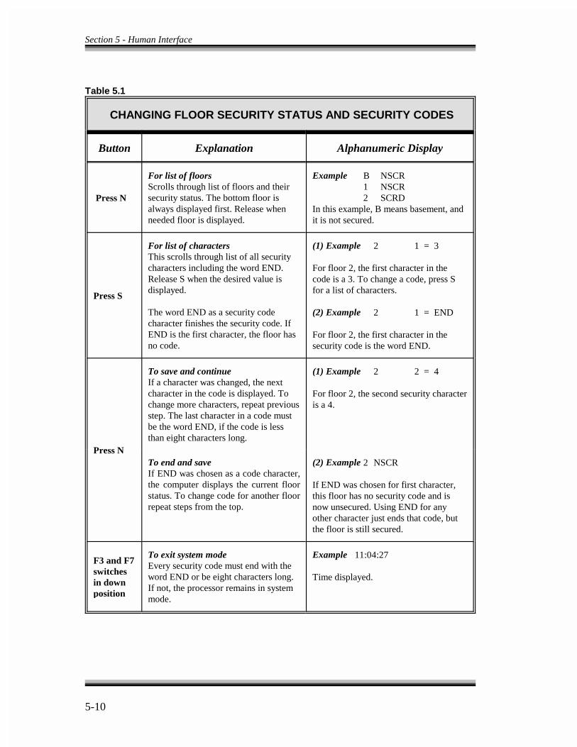
Section 5 - Human Interface
5-10
Table 5.1
CHANGING FLOOR SECURITY STATUS AND SECURITY CODES
Button Explanation Alphanumeric Display
Press N
For list of floorsScrolls through list of floors and theirsecurity status. The bottom floor isalways displayed first. Release whenneeded floor is displayed.
Example B NSCR1 NSCR2 SCRD
In this example, B means basement, andit is not secured.
Press S
For list of charactersThis scrolls through list of all securitycharacters including the word END.Release S when the desired value isdisplayed.
The word END as a security codecharacter finishes the security code. IfEND is the first character, the floor hasno code.
(1) Example 2 1 = 3
For floor 2, the first character in thecode is a 3. To change a code, press Sfor a list of characters.
(2) Example 2 1 = END
For floor 2, the first character in thesecurity code is the word END.
Press N
To save and continue (1) Example 2 2 = 4If a character was changed, the nextcharacter in the code is displayed. Tochange more characters, repeat previousstep. The last character in a code mustbe the word END, if the code is lessthan eight characters long.
For floor 2, the second security characteris a 4.
To end and save (2) Example 2 NSCRIf END was chosen as a code character,the computer displays the current floorstatus. To change code for another floorrepeat steps from the top.
If END was chosen for first character,this floor has no security code and isnow unsecured. Using END for anyother character just ends that code, butthe floor is still secured.
F3 and F7switchesin downposition
To exit system mode Example 11:04:27Every security code must end with theword END or be eight characters long.If not, the processor remains in systemmode.
Time displayed.
Section 5 - Human Interface
5-11
MCE SECURITY is initiated by the security input - BSI. To set up the security feature,see job prints in Section 7. Once in security mode, all car calls are screened by thecomputer and become registered only if: (1) the call is not to a secured floor, or (2) thefloor is secured and its code is correctly entered within ten seconds.
The security code for each floor may consist of from one to eight characters where eachcharacter is one of the floor buttons found in the elevator car. Any floor with a securitycode is a secured floor. Appendix B at the end of this manual provides instructions forsecurity operation used by elevator passengers. Room has also been provided for listingthe security codes for each floor.
5.2.4.2 SYSTEM LEARN OPERATION - Since the Series Turbo DF tractioncontroller operates under the assumption that its computer knows the exact floor and carpositions in the hoistway, the Series Turbo DF computers must learn the building beforeany attempt is made to run the car on anything other than inspection operation. Thissection describes how to put the system into learn mode. For details of the learnoperation, see Section 4.3 in this manual.
a. To place the system into the learn operation, the F4 switch (in system mode) shouldbe in the on/up position. Once on learn operation, the Alphanumeric Display, thediagnostic indicators on the front of the Swing Panel, and the Pattern GeneratorDiagnostic Indicators on the top of the Swing Panel display specific messages whichare described below. The rest of the indicators and switches are not used for thisoperation.
b. The Alphanumeric Display, while on learn operation, displays one of the followingmessages.
LRN ERR (learn error)LN READY (learn ready)LEARNING (learning)LEARNED (learn complete)
c. When the Alphanumeric Display reads LRN ERR, the diagnostic indicators display thecondition that has caused the learn error message. See Table 5.7 for a detailed listof those conditions.
d. In the learn mode, the Pattern Generator Diagnostic Indicators flash a code whichindicates that the IMC-DDP computer is in the learn mode. See Table 5.8.
Section 5 - Human Interface
5-12
5.3 IMC-GIO ON-BOARD DIAGNOSTICS -
The IMC-GIO board is a general input/output board that includes an independentprocessor which monitors the performance of the car as it approaches a terminal landing.This board is equipped with its own on-board diagnostic tools. The IMC-GIO On-BoardDiagnostics has three modes of operation.
- Startup operation- Learn operation- Normal operation
This section provides a brief description of the diagnostic tools available on the IMC-GIO board. It also gives a description of each of the three modes of operation.
5.3.1 FUNCTIONAL DESCRIPTION OF INDICATORS AND SWITCHES - Referto Figure 3.2 for the IMC-GIO board layout.
a. Four Digit Alphanumeric Display - This display is located near the upper portion ofthe IMC-GIO board. It displays the car speed, prevailing board status and errormessages.
b. Learn Indicator - This is a single green LED below the Alphanumeric Display onthe IMC-GIO board. When this LED is illuminated, it indicates that the IMC-GIOboard is on learn operation.
c. Computer On Indicator - This is a single red LED above the Alphanumeric Display.When this LED is illuminated, it indicates that the processor on the IMC-GIO isproperly executing its program. If this LED is off or is flashing on/off, it indicatesprocessor malfunction, and needs to be fixed before the car can be run safely.
d. Cutoff Indicator - This is a single red LED located above the Computer On LED.When this LED is illuminated, it indicates that the relay, on the IMC-GIO board, isnot energized and the safety processor speed pattern is substituted for the drive unit.
e. Landing System Indicators - There are three red LEDs below the Learn LED. Theseindicate the OLM and the position pulser signals.
f. Learn Switch - This toggle switch is located behind the green Learn LED on theIMC-GIO board.
g. Reset Pushbutton - This pushbutton is located above the Alphanumeric Displaybehind the Computer On LED. This pushbutton is used to reset the processor on theIMC-GIO board. When this pushbutton is depressed the Computer On LED turnsoff.
Section 5 - Human Interface
5-13
5.3.2 STARTUP OPERATION - When the system is turned on or the Computer Resetbutton is released, the processor on the IMC-GIO board goes through a self-test. This isfollowed by the display of each Limit switch input name and its associated learnedvelocity. At this time, the Cutoff LED blinks and four relay clicks can be heard. The LEDstays off and the relay stays energized. During self-test, it takes up to 30 seconds for theIMC-GIO to display all the terminal switches and their associated velocities. If the self-test is successfully performed, the Alphanumeric Display shows the car's speed as it runs,and, if the car is not running, it indicates the last speed at which the car was running. Ifthe self-test fails, the Alphanumeric Display indicates an error message. Refer to Table5.2 to identify the problem that has caused the IMC-GIO to fail the self-test.
5.3.3 IMC-GIO LEARN OPERATION - By turning on/up the Learn switch located onthe IMC-GIO board, the IMC-GIO enters the learn operation and the Learn on LEDilluminates. As the IMC-GIO goes through the learn operation, the AlphanumericDisplay shows the messages listed here.
LRN IMC-GIO on learn operation, car not movingLRNU Learning in the up directionLRND Learning in the down directionLRNW Writing the learned speed values to the EEPROMLRNR Verify the speed values in EEPROMLRNC Learning has been successfully completedLRNT In learn operation for over five minutes without completion
The learn operation is intended only for the purpose of learning the Terminal Limitswitches. The IMC-GIO should be removed from the learn operation as soon as the IMC-GIO has learned the proper velocities associated with each Terminal switch. If the Learnswitch is left in the on position for more than five minutes, the IMC-GIO automaticallyexits the learn operation and the Alphanumeric Display indicates LRNT. If, at this time,the learn is successfully completed, the car will run normally. If the learn operation wasnot complete and the EEPROM does not include valid data, the IMC-GIO processorprevents the car from running.
The EEPROM has already been programmed and tested at the factory. The factory valuesprogrammed into the EEPROM are for test purposes only and the learn operation mustbe performed before the final adjustments can be considered complete.
5.3.4 IMC-GIO NORMAL OPERATION - While on this operation, the AlphanumericDisplay constantly displays the car speed as it is traveling in the hoistway. If the car isstopped, it displays the last speed at which the car was traveling before the brakes wereapplied. If, at any time, the IMC-GIO encounters error conditions, the AlphanumericDisplay indicates one of the error conditions listed below. In this mode, the Cutoff LED

Section 5 - Human Interface
5-14
is off as long as the car makes normal approaches to the terminal landings. If the carmakes an abnormal approach to a terminal landing, the Cutoff LED would beilluminated, indicating that the relay is de-energized and that the normal speed patternhas been cut off from the drive unit.
Table 5.2
EEPROM ERROR CONDITIONS
Error Definition Correction
ERR1 EEPROM Read error Resocket EEPROM and microcontroller on the IMC-GIO board.If error repeats, call MCE Customer Service for replacement.
ERR2 Safety Relay/Serial input Verify proper operation of 12VDC relay on IMC-GIO board.error
ERR3 Not used Not used.
ERR4 Memory error during Resocket microcontroller and try to turn on the power again. Ifpower up error repeats, call MCE Customer Service for replacement.
ERR5 EEPROM checksum Resocket EEPROM and microcontroller on the IMC-GIO board.error If error repeats, call MCE Customer Service for replacement.
ERR6 EEPROM handshake Resocket EEPROM and microcontroller on the IMC-GIO board.error If error repeats, call MCE Customer Service for replacement.
ERR7 EEPROM write failure Resocket EEPROM and microcontroller on the IMC-GIO board.If error repeats, call MCE Customer Service for replacement.
ERR8 EEPROM indeterminate Hoistway must be relearned.error
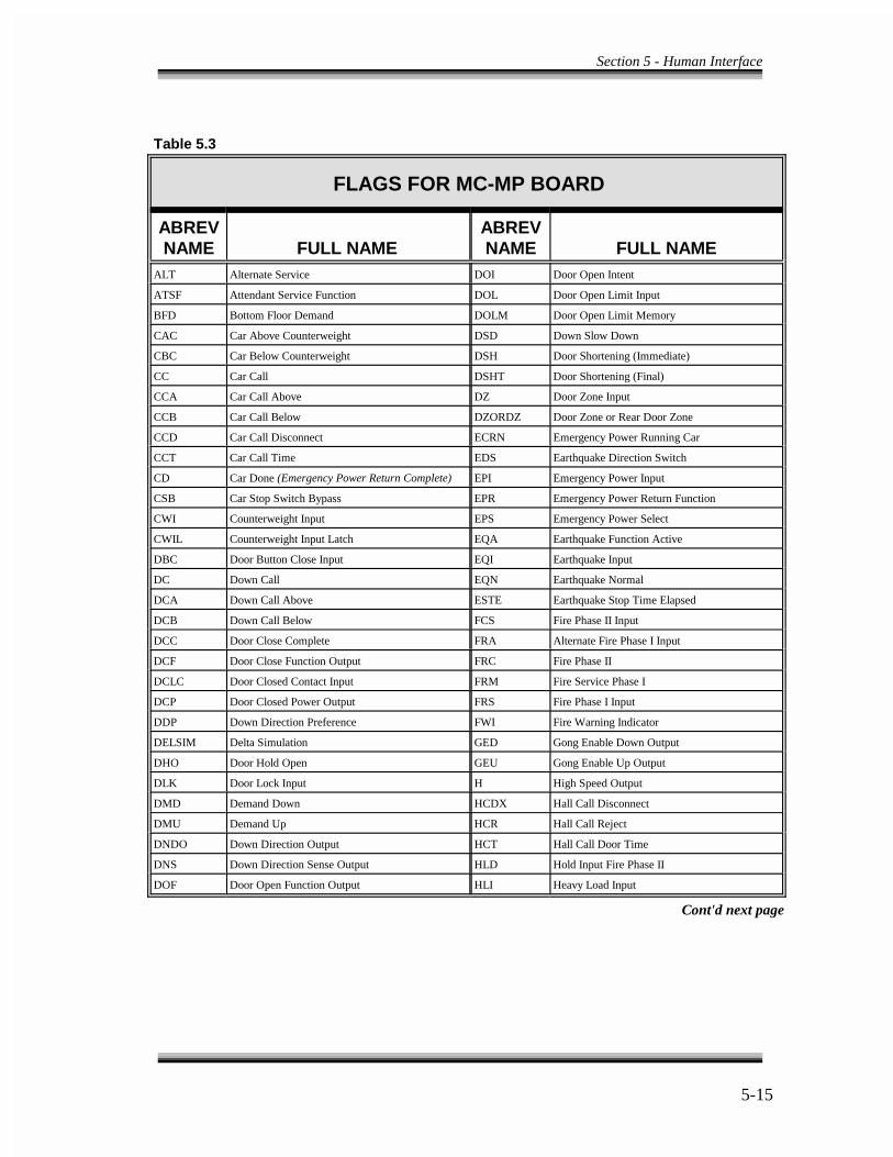
Section 5 - Human Interface
5-15
Table 5.3
FLAGS FOR MC-MP BOARD
ABREV ABREVNAME FULL NAME NAME FULL NAME
ALT Alternate Service DOI Door Open Intent
ATSF Attendant Service Function DOL Door Open Limit Input
BFD Bottom Floor Demand DOLM Door Open Limit Memory
CAC Car Above Counterweight DSD Down Slow Down
CBC Car Below Counterweight DSH Door Shortening (Immediate)
CC Car Call DSHT Door Shortening (Final)
CCA Car Call Above DZ Door Zone Input
CCB Car Call Below DZORDZ Door Zone or Rear Door Zone
CCD Car Call Disconnect ECRN Emergency Power Running Car
CCT Car Call Time EDS Earthquake Direction Switch
CD Car Done (Emergency Power Return Complete) EPI Emergency Power Input
CSB Car Stop Switch Bypass EPR Emergency Power Return Function
CWI Counterweight Input EPS Emergency Power Select
CWIL Counterweight Input Latch EQA Earthquake Function Active
DBC Door Button Close Input EQI Earthquake Input
DC Down Call EQN Earthquake Normal
DCA Down Call Above ESTE Earthquake Stop Time Elapsed
DCB Down Call Below FCS Fire Phase II Input
DCC Door Close Complete FRA Alternate Fire Phase I Input
DCF Door Close Function Output FRC Fire Phase II
DCLC Door Closed Contact Input FRM Fire Service Phase I
DCP Door Closed Power Output FRS Fire Phase I Input
DDP Down Direction Preference FWI Fire Warning Indicator
DELSIM Delta Simulation GED Gong Enable Down Output
DHO Door Hold Open GEU Gong Enable Up Output
DLK Door Lock Input H High Speed Output
DMD Demand Down HCDX Hall Call Disconnect
DMU Demand Up HCR Hall Call Reject
DNDO Down Direction Output HCT Hall Call Door Time
DNS Down Direction Sense Output HLD Hold Input Fire Phase II
DOF Door Open Function Output HLI Heavy Load Input
Cont'd next page
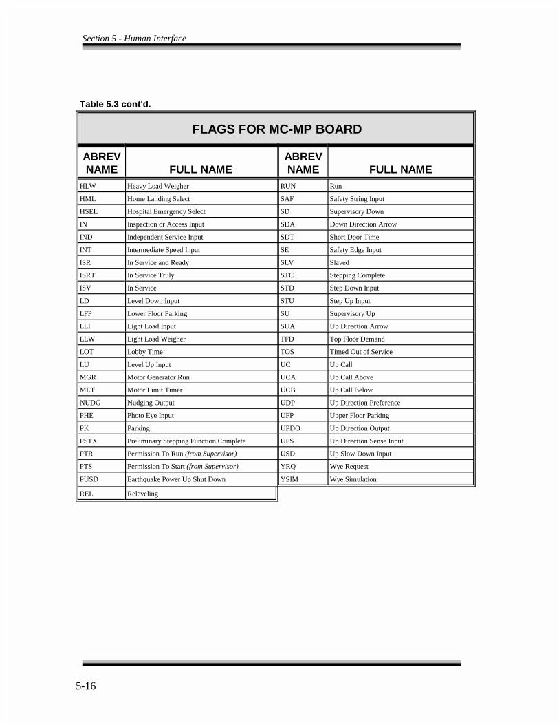
Section 5 - Human Interface
5-16
Table 5.3 cont'd.
FLAGS FOR MC-MP BOARD
ABREV ABREVNAME FULL NAME NAME FULL NAME
HLW Heavy Load Weigher RUN Run
HML Home Landing Select SAF Safety String Input
HSEL Hospital Emergency Select SD Supervisory Down
IN Inspection or Access Input SDA Down Direction Arrow
IND Independent Service Input SDT Short Door Time
INT Intermediate Speed Input SE Safety Edge Input
ISR In Service and Ready SLV Slaved
ISRT In Service Truly STC Stepping Complete
ISV In Service STD Step Down Input
LD Level Down Input STU Step Up Input
LFP Lower Floor Parking SU Supervisory Up
LLI Light Load Input SUA Up Direction Arrow
LLW Light Load Weigher TFD Top Floor Demand
LOT Lobby Time TOS Timed Out of Service
LU Level Up Input UC Up Call
MGR Motor Generator Run UCA Up Call Above
MLT Motor Limit Timer UCB Up Call Below
NUDG Nudging Output UDP Up Direction Preference
PHE Photo Eye Input UFP Upper Floor Parking
PK Parking UPDO Up Direction Output
PSTX Preliminary Stepping Function Complete UPS Up Direction Sense Input
PTR Permission To Run (from Supervisor) USD Up Slow Down Input
PTS Permission To Start (from Supervisor) YRQ Wye Request
PUSD Earthquake Power Up Shut Down YSIM Wye Simulation
REL Releveling
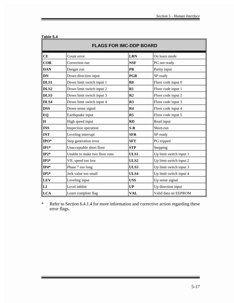
Section 5 - Human Interface
5-17
Table 5.4
FLAGS FOR IMC-DDP BOARD
CE LRNCount error On learn mode
COR NSFCorrection run PG not ready
DAN PRDanger run Parity input
DN PGRDown direction input SP ready
DLS1 R0Down limit switch input 1 Floor code input 0
DLS2 R1Down limit switch input 2 Floor code input 1
DLS3 R2Down limit switch input 3 Floor code input 2
DLS4 R3Down limit switch input 4 Floor code input 3
DSS R4Down sense signal Floor code input 4
EQ R5Earthquake input Floor code input 5
H RDHigh speed input Read input
INS S-RInspection operation Short-run
INT SFRLeveling interrupt SP ready
IPO* SFTStep generation error PG tripped
IP1* STPUnacceptable short floor Stepping
IP2* ULS1Unable to make two floor runs Up limit switch input 1
IP3* ULS2VIL speed too low Up limit switch input 2
IP4* ULS3Phase 7 too long Up limit switch input 3
IP5* ULS4Jerk value too small Up limit switch input 4
LEV USSLeveling input Up sense signal
LI UPLevel inhibit Up direction input
LCA VALLearn complete flag Valid data on EEPROM
* Refer to Section 6.4.1.4 for more information and corrective action regarding theseerror flags.
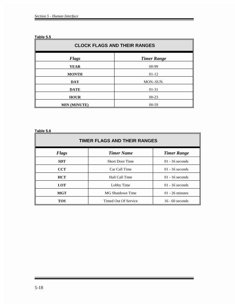
Section 5 - Human Interface
5-18
Table 5.5
CLOCK FLAGS AND THEIR RANGES
Flags Timer Range
YEAR 00-99
MONTH 01-12
DAY MON.-SUN.
DATE 01-31
HOUR 00-23
MIN (MINUTE) 00-59
Table 5.6
TIMER FLAGS AND THEIR RANGES
Flags Timer Name Timer Range
SDT Short Door Time 01 - 16 seconds
CCT Car Call Time 01 - 16 seconds
HCT Hall Call Time 01 - 16 seconds
LOT Lobby Time 01 - 16 seconds
MGT MG Shutdown Time 01 - 26 minutes
TOS Timed Out Of Service 16 - 60 seconds

Section 5 - Human Interface
5-19
COMPUTER SWING PANEL FRONT VIEWFIGURE 5.1
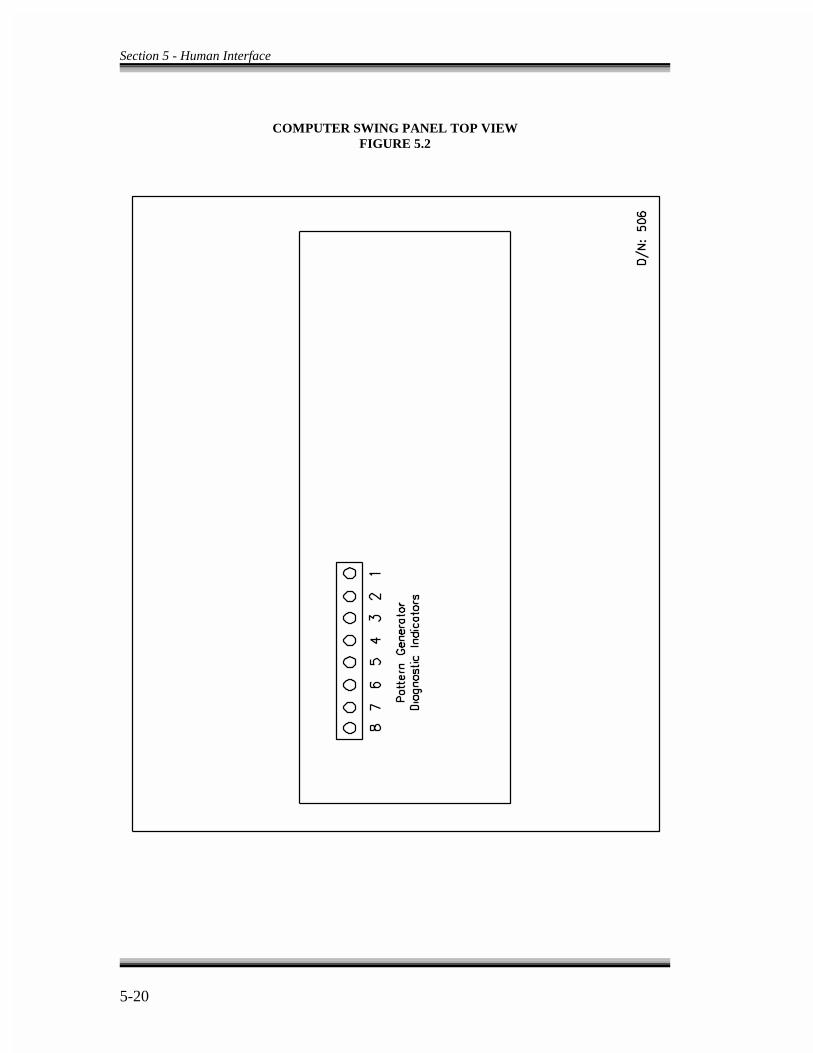
Section 5 - Human Interface
5-20
COMPUTER SWING PANEL TOP VIEWFIGURE 5.2

Section 5 - Human Interface
5-21
COMPUTER SWING PANEL BACKPLATEFIGURE 5.3
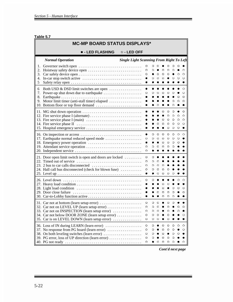
Section 5 - Human Interface
5-22
Table 5.7
MC-MP BOARD STATUS DISPLAYS*
�� - LED FLASHING �� - LED OFF
Normal Operation Single Light Scanning From Right To Left
1. Governor switch open . . . . . . . . . . . . . . . . . . . . . . . . . . . . . . . . . 2. Hoistway safety device open . . . . . . . . . . . . . . . . . . . . . . . . . . . . 3. Car safety device open . . . . . . . . . . . . . . . . . . . . . . . . . . . . . . . . . 4. In-car stop switch active . . . . . . . . . . . . . . . . . . . . . . . . . . . . . . . 5 Safety relay open . . . . . . . . . . . . . . . . . . . . . . . . . . . . . . . . . . . . .
� � � � � � � �
� � � � � � � �
� � � � � � � �
� � � � � � � �
� � � � � � � �
6 Both USD & DSD limit switches are open . . . . . . . . . . . . . . . . . 7. Power-up shut down due to earthquake . . . . . . . . . . . . . . . . . . . . 8. Earthquake . . . . . . . . . . . . . . . . . . . . . . . . . . . . . . . . . . . . . . . . . . 9. Motor limit timer (anti-stall timer) elapsed . . . . . . . . . . . . . . . . .10. Bottom floor or top floor demand . . . . . . . . . . . . . . . . . . . . . . . .
� � � � � � � �
� � � � � � � �
� � � � � � � �
� � � � � � � �
� � � � � � � �
11. MG shut down operation . . . . . . . . . . . . . . . . . . . . . . . . . . . . . . .12. Fire service phase I (alternate) . . . . . . . . . . . . . . . . . . . . . . . . . . .13. Fire service phase I (main) . . . . . . . . . . . . . . . . . . . . . . . . . . . . .14. Fire service phase II . . . . . . . . . . . . . . . . . . . . . . . . . . . . . . . . . .15. Hospital emergency service . . . . . . . . . . . . . . . . . . . . . . . . . . . . .
� � � � � � � �
� � � � � � � �
� � � � � � � �
� � � � � � � �
� � � � � � � �
16. On inspection or access . . . . . . . . . . . . . . . . . . . . . . . . . . . . . . . .17. Earthquake normal reduced speed mode . . . . . . . . . . . . . . . . . . .18. Emergency power operation . . . . . . . . . . . . . . . . . . . . . . . . . . . .19. Attendant service operation . . . . . . . . . . . . . . . . . . . . . . . . . . . . .20. Independent service . . . . . . . . . . . . . . . . . . . . . . . . . . . . . . . . . . .
� � � � � � � �
� � � � � � � �
� � � � � � � �
� � � � � � � �
� � � � � � � �
21. Door open limit switch is open and doors are locked . . . . . . . . .22. Timed out of service . . . . . . . . . . . . . . . . . . . . . . . . . . . . . . . . . .23. 2 bus to car calls disconnected . . . . . . . . . . . . . . . . . . . . . . . . . .24. Hall call bus disconnected (check for blown fuse) . . . . . . . . . . .25. Level up . . . . . . . . . . . . . . . . . . . . . . . . . . . . . . . . . . . . . . . . . . . .
� � � � � � � �
� � � � � � � �
� � � � � � � �
� � � � � � � �
� � � � � � � �
26. Level down . . . . . . . . . . . . . . . . . . . . . . . . . . . . . . . . . . . . . . . . .27. Heavy load condition . . . . . . . . . . . . . . . . . . . . . . . . . . . . . . . . . .28. Light load condition . . . . . . . . . . . . . . . . . . . . . . . . . . . . . . . . . .29. Door close failure . . . . . . . . . . . . . . . . . . . . . . . . . . . . . . . . . . . .30. Car-to-Lobby function active . . . . . . . . . . . . . . . . . . . . . . . . . . . .
� � � � � � � �
� � � � � � � �
� � � � � � � �
� � � � � � � �
� � � � � � � �
31. Car not at bottom (learn setup error) . . . . . . . . . . . . . . . . . . . . . .32. Car not on LEVEL UP (learn setup error) . . . . . . . . . . . . . . . . . .33. Car not on INSPECTION (learn setup error) . . . . . . . . . . . . . . .34. Car not below DOOR ZONE (learn setup error) . . . . . . . . . . . . .35. Car is on LEVEL DOWN (learn setup error) . . . . . . . . . . . . . . .
� � � � � � � �
� � � � � � � �
� � � � � � � �
� � � � � � � �
� � � � � � � �
36. Loss of IN during LEARN (learn error) . . . . . . . . . . . . . . . . . . .37. No response from PG board (learn error) . . . . . . . . . . . . . . . . . .38. On both leveling switches (learn error) . . . . . . . . . . . . . . . . . . . .39. PG error, loss of UP direction (learn error) . . . . . . . . . . . . . . . . .40. PG not ready . . . . . . . . . . . . . . . . . . . . . . . . . . . . . . . . . . . . . . . .
� � � � � � � �
� � � � � � � �
� � � � � � � �
� � � � � � � �
� � � � � � � �
Cont'd next page
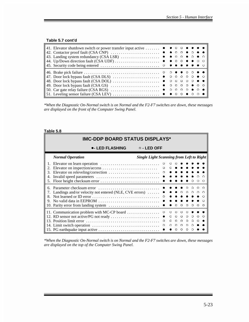
Section 5 - Human Interface
5-23
Table 5.7 cont'd
41. Elevator shutdown switch or power transfer input active . . . . . . .42. Contactor proof fault (CSA CNP) . . . . . . . . . . . . . . . . . . . . . . . .43. Landing system redundancy (CSA LSR) . . . . . . . . . . . . . . . . . . .44. Up/Down direction fault (CSA UDF) . . . . . . . . . . . . . . . . . . . . . .45. Security code being entered . . . . . . . . . . . . . . . . . . . . . . . . . . . . .
� � � � � � � �
� � � � � � � �
� � � � � � � �
� � � � � � � �
� � � � � � � �
46. Brake pick failure . . . . . . . . . . . . . . . . . . . . . . . . . . . . . . . . . . . . .47. Door lock bypass fault (CSA DLS) . . . . . . . . . . . . . . . . . . . . . . .48. Door lock bypass fault (CSA DOL) . . . . . . . . . . . . . . . . . . . . . . .49. Door lock bypass fault (CSA GS) . . . . . . . . . . . . . . . . . . . . . . . .50. Car gate relay failure (CSA RGS) . . . . . . . . . . . . . . . . . . . . . . . .51. Leveling sensor failure (CSA LEV) . . . . . . . . . . . . . . . . . . . . . . .
� � � � � � � �
� � � � � � � �
� � � � � � � �
� � � � � � � �
� � � � � � � �
� � � � � � � �
*When the Diagnostic On-Normal switch is on Normal and the F2-F7 switches are down, these messagesare displayed on the front of the Computer Swing Panel.
Table 5.8
IMC-DDP BOARD STATUS DISPLAYS*
��- LED FLASHING �� - LED OFF
Normal Operation Single Light Scanning from Left to Right
1. Elevator on learn operation . . . . . . . . . . . . . . . . . . . . . . . . . . . . . 2. Elevator on inspection/access . . . . . . . . . . . . . . . . . . . . . . . . . . . 3. Elevator on releveling/correction . . . . . . . . . . . . . . . . . . . . . . . . . 4. Invalid speed parameters . . . . . . . . . . . . . . . . . . . . . . . . . . . . . . . 5. Floor height checksum error . . . . . . . . . . . . . . . . . . . . . . . . . . . . .
� � � � � � � �
� � � � � � � �
� � � � � � � �
� � � � � � � �
� � � � � � � �
6. Parameter checksum error . . . . . . . . . . . . . . . . . . . . . . . . . . . . . . 7. Landings and/or velocity not entered (NLE, CVE errors) . . . . . . 8. Not learned or ID error . . . . . . . . . . . . . . . . . . . . . . . . . . . . . . . . . 9. No valid data in EEPROM . . . . . . . . . . . . . . . . . . . . . . . . . . . . . .10. Parity error from landing system . . . . . . . . . . . . . . . . . . . . . . . . .
� � � � � � � �
� � � � � � � �
� � � � � � � �
� � � � � � � �
� � � � � � � �
11. Communication problem with MC-CP board . . . . . . . . . . . . . . . .12. RD sensor not active/PG not ready . . . . . . . . . . . . . . . . . . . . . . . .13. Position limit error . . . . . . . . . . . . . . . . . . . . . . . . . . . . . . . . . . . .14. Limit switch operation . . . . . . . . . . . . . . . . . . . . . . . . . . . . . . . . .15. PG earthquake input active . . . . . . . . . . . . . . . . . . . . . . . . . . . . . .
� � � � � � � �
� � � � � � � �
� � � � � � � �
� � � � � � � �
� � � � � � � �
*When the Diagnostic On-Normal switch is on Normal and the F2-F7 switches are down, these messagesare displayed on the top of the Computer Swing Panel.
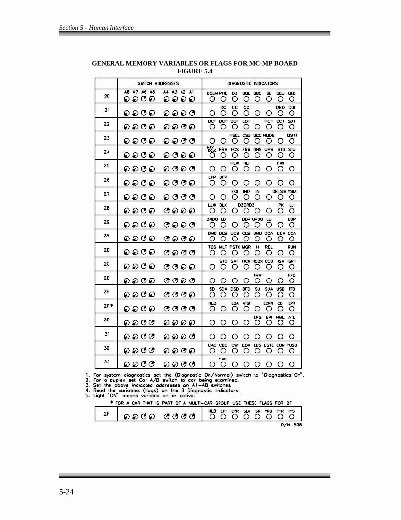
Section 5 - Human Interface
5-24
GENERAL MEMORY VARIABLES OR FLAGS FOR MC-MP BOARDFIGURE 5.4
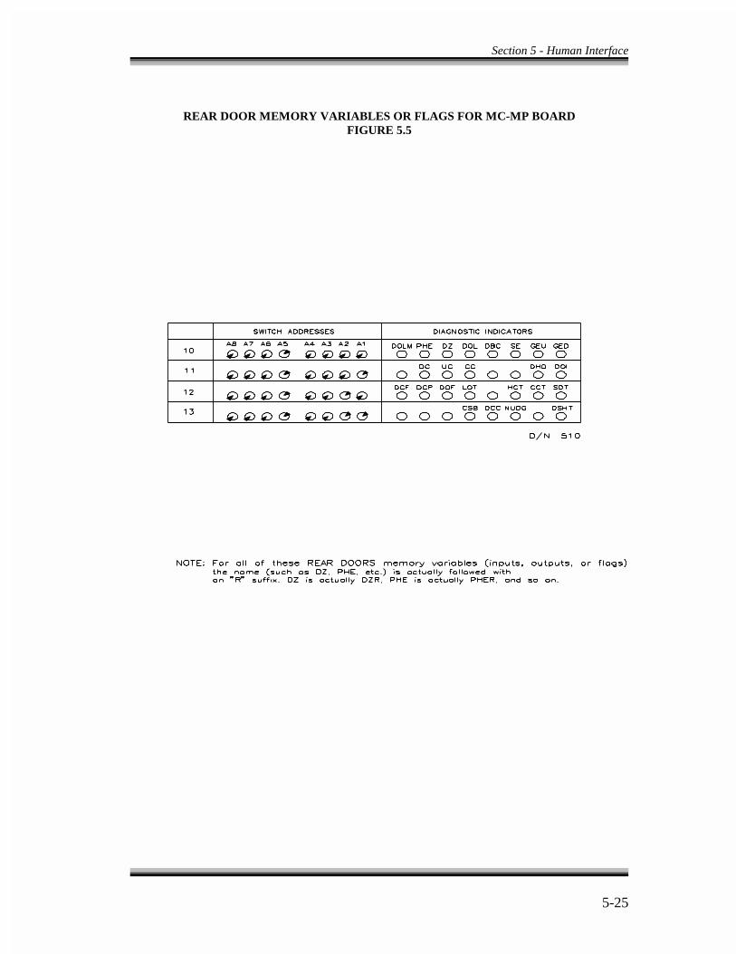
Section 5 - Human Interface
5-25
REAR DOOR MEMORY VARIABLES OR FLAGS FOR MC-MP BOARDFIGURE 5.5
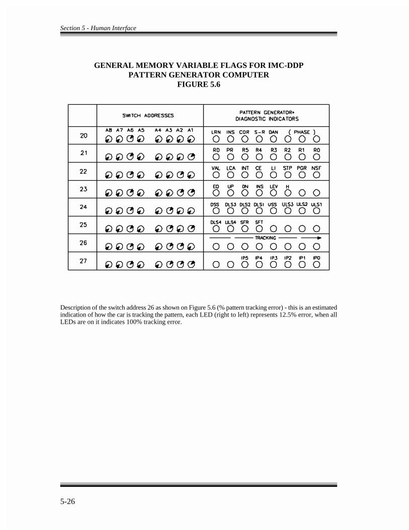
Section 5 - Human Interface
5-26
GENERAL MEMORY VARIABLE FLAGS FOR IMC-DDPPATTERN GENERATOR COMPUTER
FIGURE 5.6
Description of the switch address 26 as shown on Figure 5.6 (% pattern tracking error) - this is an estimatedindication of how the car is tracking the pattern, each LED (right to left) represents 12.5% error, when allLEDs are on it indicates 100% tracking error.
6-1
SECTION - 6
DESCRIPTION OF OPERATION ANDTROUBLESHOOTING GUIDE
6.0 GENERAL INFORMATION -
The VVMC-1000 Series Turbo DF controllers possess features which are especiallyhelpful in speeding up troubleshooting. Signals can be traced from field wires to theboards and the computer without mechanical removal of components, nor is it necessaryto access the boards from the rear. This section covers the use of the diagnostic featuresand the troubleshooting process.
The Enhanced On-Board Diagnostics (EOD) is the most helpful tool for troubleshooting.Therefore, it is best to start with the EOD station. In many cases, the computer indicatesthe source of the problem. Refer to Section 5.2 - Enhanced On-Board Diagnostics. Whenviewing the diagnostic indicators, pay special attention to contradictory information. Forexample, the High Speed light should not be on with Doors Locked light off.
6.1 TRACING SIGNALS IN THE CONTROLLER -
In many cases the malfunction of the control system is caused by a bad input or outputsignal. Inputs are signals that are generated outside the controller cabinet and are broughtto the designated terminals inside the controller cabinet where they are read by thecomputer. Outputs are signals that are generated inside the computer and are availableon terminal blocks inside the controller cabinet. Since a fault on any input or output canbe a cause of system malfunction, it is essential to be able to trace these signals andlocate the source of the problem. The following is an example which shows how an inputsignal can be traced from its point of origin to its destination inside the computer. Usingthe EOD instructions in Section 5.2, set up the diagnostic switches so that the door zone(DZ) light can be observed. This light shows the status of the door zone (DZ) input. SeeFigure 5.4. Moving the car in the hoistway should cause this light to turn on/off,whenever the car goes through a floor. If the status of the DZ indicator does not change,investigate the following possible causes. 1. A defective door zone switch2. Incorrect hoistway wiring3. Bad termination of hoistway wiring to the DZ terminal inside the controller4. A defect on the HC-RB relay board or HC-PI/O board

Section 6 - Troubleshooting
6-2
NOTE
If you have rear doors and at least one floor where both openings exist,you should use the EOD to look at the rear door zone input DZR aswell. DZR enters the system on the HC-RDRB board and comes fromthe rear door zone sensor.
The first step is to determine whether the problem is inside or outside the controller. Toestablish this, use a voltmeter to probe the door zone terminal (27). This terminal is inarea 3 of the job print, (areas of the job prints are marked on the left hand side of thesheets, and certain signals may be in different locations from the print area mentioned inthis guide). Moving the car in the hoistway should cause the voltmeter to read 120VACwhen the car is at door zone. If the signal read by the voltmeter does not change when thecar passes the door zone, then the problem must be external to the controller, and items1, 2 or 3 should be examined. If the signal read by the voltmeter does change as the carpasses the Door Zone, the problem must be internal to the controller, and item 4 must beexamined. The print shows that this input goes to the right hand side of the DZ relay toa 47K 1W resistor, to pin 8 of the C2 connector on the HC-RB relay board and then topin 8 of the C2 connector on the HC-PI/O board.
Figures 6.1 and 6.2 show the HC-PI/O and the HC-RB boards, and indicate the locationof the DZ signal. If power is present on terminal 27, there should be approximately120VAC at the bottom of the 47K 1W resistor corresponding to DZ, whereas the top ofthe same resistor should read approximately 5VAC.
The HC-RB board has test pads on the front for every relay and connector. The lowerleft-hand side of the relay is inscribed with a legend indicating which pad correspondsto which contact of the relay or its coil. To verify that voltage from terminal 27 isproceeding to the relay coil, use the test pad on the lower right hand side of the DZ relay(the right hand side of the relay coil symbol on the job print corresponds to the right handside on the board). It is, therefore, not necessary to remove the relay, nor to access theback of the HC-RB board in order to trace the signals on the board.
The signals can also be traced on the HC-PI/O board. See Figure 6.1 for details.
If the signal gets to the HC-PI/O board but does not get to the computer, the problem isprobably on the HC-PI/O board.

Section 6 - Troubleshooting
6-3
6.2 DOOR LOGIC -
As complex as it seems, the door logic portion of the software only answers onequestion: Should the doors be open? The computer looks at selected inputs, and callsupon its logic to answer this question. These inputs and the flags generated by thecomputer's logic may be viewed through the Enhanced On-Board Diagnostics facility.When troubleshooting a door problem, the first priority is to inspect the action andsequence of these flags and inputs. The state of these flags indicate the problem. It isadvisable to be familiar with the meaning of the associated flags. Once the computer hasdetermined the answer to the door status question, appropriate outputs are turned on/offin an attempt to bring the doors to the desired state.
Here are the selected inputs at which the computer looks to answer the door question.
DBC - Door button close inputDCLC - Door closed contact input (retiring cam only)DLK - Door lock inputDOB - Safety edge input (door open button) DOL - Door open limit inputDZ - Door zone inputPHE - Photo eye input
The computer then generates these outputs.
DCF - Door close function outputDCP - Door close power outputDOF - Door open function output
These are associated computer-generated logic flags.
CCT - Car call time flagDOI - Door open intent flagDSH - Door shortening (car call) flagDSHT - Door shortening flagHCT - Hall call time flagLOT - Lobby call time flagSDT - Short door time flag
The flags and inputs shown above are used by the computer to decide whether the doorsshould be open or closed. The DOI (Door Open Intent) flag reflects the computer'sdecision. If the computer recognizes a valid reason either to open the doors or keep themopen, this internal flag will be turned on, and can be viewed using the Enhanced On-
Section 6 - Troubleshooting
6-4
Board Diagnostics facility. The LED in the diagnostics system which corresponds to theDOI turns on when the computer decides that the doors should be open. If, on the otherhand, the computer decides that the doors should be closed, the DOI flag would turn off,and the corresponding LED would no longer be highlighted.
So it is clear that the DOI flag is useful for troubleshooting door problems. It indicatesthe intention of the computer concerning the state of the doors.
Remember that if DOI is on, it turns on the DOF output which should then pick the DOrelay. The door should open until the DOL (Door Open Limit) input ceases. When theDOL stops it shuts off the DOF output while the doors are standing open and DOI is on.When DOI goes away, the DCF output goes on and picks the DC relay, which moves thedoors closed. As long as there is no demand to go anywhere, the signal that shuts off theDCF output is DLK (Doors Locked), or DCLC, if the car has a retiring cam. There is,however, a delay of approximately two seconds from the time the doors are locked to theDCF output turning off. If there is any demand (e.g., the DMU or DMD flags are on) andif DOI is not on, then the DCP output turns on regardless of the position of the door. TheDCP output is provided for door closing power for those door operators requiring it, suchas those made by G.A.L. corporation.
There are several door standing open time values. The one in use is determined by thetype of call to which the car has responded or which has been canceled. An HCT flag isa hall call cancellation. A car call cancellation gives a CCT flag. A door reopen from ahall or car button at the lobby or a lobby hall or car call cancellation is indicated by aLOT flag. A door reopen from the photo eye or safety edge is indicated by an SDT flag.Each of these flags, HCT, CCT, SDT or LOT gives a separate door standing open time.
The door logic provides protection timers for the door equipment in both the open andthe closed direction. If the doors get stuck as a result of the door interlock keeper failingto lift high enough to clear the door interlock during the opening cycle, then the doorscannot complete their opening cycle. This could damage the door motor. The door openprotection timer eventually gives up trying to open the doors and the car would then beable to proceed to the next call. Similarly, if the doors do not close all the way (e.g., thedoors do not lock), the computer cycles through the door opening logic at programmedintervals in an attempt to clear the problem. The computer's logic impels it to look for a reason to open the doors. If a valid reason toopen the doors is not found or if conditions are detected that prohibit the opening of thedoors, the logic closes the doors (i.e., resets or turns off DOI). In order to open the doors,the car must be in door zone. It cannot be running at high or intermediate speed. Oncethe car has settled into a proper position to open the doors, there must be a condition to
Section 6 - Troubleshooting
6-5
indicate to the logic that the doors should be open. Some of these conditions are listedhere.
- Call demand at the current landing (or, a call has just been canceled)- Safety edge/door open button input- Emergency/independent service conditions - Photo eye input
When a call is canceled, one of the following door time flags should be turned on: CCT,HCT, or LOT. When one of the reopening devices is active (SE or PHE) the SDT flagshould be set. When emergency or independent service condition exists, that conditioncauses the DOI flag to be set. These conditions include: fire service, emergency poweroperation, independent service, and attendant service.
Once the intention of the computer is understood, the high voltage hardware should beinspected to see if the appropriate functions are being carried out. For example, if thedoors are closed and DOI is set, the doors should be opening (i.e., the DO relay picked).If the doors are open and the DOI is turned off, the doors should be closing (the DC relaypicked).
If the door control system does not seem to be doing what the mechanic expects, thenunderstanding the computer's logic becomes important. At these times it is vital todetermine whether or not the control system is doing what it thinks it should be doing.If the control system (high voltage section) is doing what the logic is intending it to do,it is important to determine how the logic was obtained. If the control system is not doingwhat the logic is intending it to do, then it is important to determine what is preventingthe desired function from being carried out (e.g., bad relay, bad triac, etc.). Thediagnostic facility on the Computer Swing Panel (and/or CRT) determines whichsituation is present. The output flags show which outputs the computer is attempting toturn on/off and these flags should be compared with what is actually happening in thehigh voltage hardware.
Consider, as an example, this problem: the doors are closed and locked on the car, butthe DC relay is always picked. This prevents the doors from opening when they should.The important point is the intention of the computer. Inspection of the diagnostic systemnarrows it down. The cause of the problem must first be isolated.
- If both the DCF and DCP flags are turned off in the computer, the DC relay shouldnot be picked. If the DC relay is picked, then it is obvious that the problem is in theoutput string to the DC relay.
Section 6 - Troubleshooting
6-6
- If either the DCF or DCP flag is always set in the computer, the problem is not withthe output circuit. (It may be a problem with the door lock circuitry.)
- If the doors are truly physically locked, inspect the DLK flag in the computer. If theflag is not set in the computer, the fault is in the input circuit from the door lockinput.
6.3 CALL LOGIC -
6.3.1 NORMAL OPERATION - In the MCE call input structure, calls are input to thesystem by grounding the appropriate call input, as labeled on the call board (HC-CI/O).Physically grounding the call input terminal illuminates the corresponding call indicatorLED on the call board. Recognition and acceptance (latching) of the call by the computercauses the indicator to remain lit on the board. Cancellation of the call causes theindicator to turn off. In this call input/output structure, the single input/output terminalon the call board accepts call inputs from the call fixtures and serves as the outputterminal which illuminates the call fixtures, indicating registration of the call. This meansthat the field wiring is identical to that which would be used for a standard relaycontroller. Calls may be prevented from latching by the computer. If car calls are not being allowedto register, the computer may be purposely preventing this registration. When thecomputer prevents car call registration, it turns on the Car Call Disconnect flag (CCD)for that car. Inspection of this flag in the diagnostics reveals whether or not it is thecomputer itself preventing the registration of these calls. If the CCD flag is indeed on,the reason for this CCD condition must be discovered. There are several possible reasonsfor a CCD condition. Among them are fire service, a motor limit timer elapsed condition,bottom or top floor demand.
A corresponding flag exists for Hall Call registration prevention. The computer maydetect conditions for preventing hall calls from being registered and set the Hall CallDisconnect Flag (HCDX). This is a system flag, as opposed to a per car flag. It isavailable for viewing in the diagnostic display, along with each car's operating flags.There are several possible reasons the computer might reject hall call registration.Among them are fire service, a hall call bus problem, or no available cars in service torespond to hall calls.
If a call circuit becomes damaged or stuck on because the pushbutton itself is stuck, theelevator releases itself automatically. It will probably return there later, but will releaseitself again automatically, thereby allowing continued service in the building.
Section 6 - Troubleshooting
6-7
IMPORTANT
If there is a call problem, first disconnect the field wire or wires from that callterminal to find out if the problem is on the board. Disconnect the calls byunplugging the terminals, or removing individual wires. If the individual fieldwire is disconnected, tighten the screw terminal lightly since contact might notbe made if the terminal is grounded, using a jumper when the screw on theterminal is loose. Next, refer to Section 5.2.3.2 - Viewing and Entering Calls,and verify whether the call is being recognized by the computer. Prepare ajumper with one end connected to terminal #1, which is ground (subplate isgrounded), and use the other end to enter the call by grounding the call terminalin question.
6.3.2 PREPARATION FOR TROUBLESHOOTING CALL CIRCUITS -
6.3.3 TROUBLESHOOTING -
1. After the wires are disconnected from the call input terminal, turn on power at themain disconnect. Put the car in a normal running mode. Use the system diagnosticsto check the status of the HCDX flag and CCD flag which, if on, will shut off hallcalls and car calls respectively.
2. If HCDX and CCD are normal or off, check the voltage on the call terminal inquestion with a meter which has a fairly high input impedance, such as a good digitalmeter. The voltage for which the call circuits were set up should roughly correspondto the voltage on the call terminal (it can be up to 15% less). If the voltage is lowerthan that, shut off the power and remove the resistor-fuse associated with the callterminal. For example, if the call terminal is the third one up from the bottom,remove the third resistor-fuse from the bottom. Turn the power back on, and read thevoltage. If the necessary voltage is still not present, verify that the jumper plug, orheader, is in position on the call board, and that the correct amount of power iscoming into the terminals on the call board which are marked PS1, PS2 and PS3.There may be power on all these terminals, or just two, or at least one. This dependson the type of calls on the board.
3. The jumper plug socket is located on the right side of the call board near the callindicators. If a call board is replaced, this jumper plug must always be transferred tothe new board, and must stay with that board position. If this plug is not installed, any
Section 6 - Troubleshooting
6-8
NOTE
There are three versions of the resistor-fuse. Older jobs may have eithera single 22 ohm ¼ watt resistor or a single 10V zener diode. On morerecent jobs, this resistor-fuse is an assembly made up of a 10V zener anda 22 ohm ¼ watt resistor.
calls on that board may become registered if the field wiring is not hooked up. Besure the jumper plug is in place. See Figure 6.3.
4. Once the proper power on the call terminal is obtained, use the instructions for useof the Enhanced On-Board Diagnostics to examine the call. The call should not belit. If it is lit, reset the computer for that car to be sure the CCD flag is turned off. Ifnecessary, reset the computer on the group supervisory system to reset a hall call thatis latched, if the car is part of a group. With the resistor-fuse removed, field wiresdisconnected, HCDX and CCD both off, and proper voltage on the call terminal, thecall should not be registered. Shorting the call terminal to terminal 1, or ground,should register the call in the computer. This does not mean the call registered lighton the call board will now work correctly. If the call does not register, and cancel,after following these steps, it may be an indication that a condition exists on theboard that cannot be corrected in the field and the board should be replaced.
5. If the call worked correctly in the previous step, and if the call is not registered, theindicator for that call on the board will glow dimly if the board is not arranged forneon indicator lamps. If the board is arranged for neon indicators, the call indicatoron the board will not glow when the call is not registered.
6. With a good resistor-fuse plugged into the proper call position, verify that theindicator on the call board works correctly. That is to say, it should glow brightlywhen the call is registered and glow dimly, or not at all, when the call is notregistered. If the call indicator burns brightly as soon as the resistor-fuse is pluggedin and shows no change in brightness whether the call is registered or not, a bad triac,or triac driver transistor, is indicated. If the triac is a plug-in type, try replacing it. Ifit is not a plug-in type, the board will have to be sent back to the factory to berepaired. Usually, if a triac has failed, it measures as a short circuit from the metalflag sticking up in the air to terminal 1 with the power disconnected and the field wireremoved. If the call board is not in the system, check it for a short between the metalflag on the triac to any pad area around a mounting screw hole. The bottom-most triac

Section 6 - Troubleshooting
6-9
on the call board corresponds to the bottom-most terminal. The terminals and triacsfollow upward in this way. See Figure 6.3.
7. If the call seems to work properly in the previous step, but stays latched on, eventhough the car arrives at that landing (especially if it is a car call), remove theresistor-fuse and put it back. Be careful: the circuits may be 120VAC to ground. If thecall is now canceled, replace the board, or have it repaired at the factory.
8. If the call has passed all of the previous tests, it is working properly as long as thefield wires are not attached. Before reconnecting the field wires, connect a jumper toground or terminal 1 and press that hall, or car call, pushbutton. If a fuse blows, it isa field wiring problem. If no fuse blows, connect the call wires and test them. Ifconnecting the call wires causes a problem, the call board may have been damagedagain. The important concept is that once the call board is working properly any otherproblems will probably be field wiring problems.
6.4 PATTERN GENERATOR TROUBLESHOOTING -
The pattern generator hardware and software, which is described in Section 1 and 4,either creates a motion pattern or terminates the pattern because of an unsafe condition.The Enhanced On-Board Diagnostics (EOD) and the CRT help identify the reason(s) forfailure to create the desired pattern or for pattern termination. Section 5 has a completedescription of the use of the EOD for troubleshooting the pattern generator. The CRTprovides the elevator mechanic with a convenient means of diagnosing pattern generatorproblems.
6.4.1 USING THE CRT TERMINAL FOR TROUBLESHOOTING THEPATTERN GENERATOR - The CRT terminal provides three basic screens whichdisplay functions relating to the pattern generator and related system statuses. Instructionon how to obtain the different screens on the CRT is in the MCE Computer PeripheralManual.
6.4.1.1 ELEVATOR GRAPHIC DISPLAY F3 SCREEN - As shown in Figure 4.4 theF3 screen is divided into two separate blocks, the hoistway graphic display, and the carstatus and pattern generator status display.
a. The Hoistway Graphic Display - This display indicates the car position, directionarrows, car calls and assigned hall calls and the position of the doors. The distancebetween any two adjacent floors is displayed in the column called PG Count. Thenumber displayed is the number of .1875" increments comprising this distance.

Section 6 - Troubleshooting
6-10
b. The Car Status and Pattern Generator Status Display - The upper portion of thisdisplay describes the current status of the car, and is self-explanatory. The remainingpart of this display is the pattern generator status and may consist of the statuses ofrelated inputs, and other messages, as well as car velocity, car position from last stopand car position measured from the bottom landing. A detailed description of thesemessages follows. They divide into three categories.
1. Messages relating to the prevention of the PG Ready signal, which is necessaryfor the pattern to begin a normal acceleration sequence. The prevention of PGReady signal is PG Not Ready, accompanied by the message which indicates thecondition preventing the PG Ready signal from being generated. These messagesare listed below and are accompanied by an explanation of each message.
EPRD: This message is EEPROM read error, which means that the data read bythe PG computer from the EEPROM memory are not valid. This error can occurin several ways. These are explained below, accompanied by an additionalmessage.
IDME: ID mismatch. The IMC-DDP computer continuously compares the IDcode stored in its own EEPROM to the car ID stored in the MC-MP board. If thetwo IDs do not match, the car would be prevented from running, and an EPRDerror would be generated. This could occur if the elevator mechanic swaps the oldIMC-DDP computer with a new one without swapping the proper EEPROM chipor if the EEPROM chip was exchanged with a chip that does not include theproper ID. Correct this situation by relearning the hoistway floor positions andreentering the speed parameters, or by keeping the original EEPROM from theold board and placing it in the new board.
MPIDE: Invalid ID from MC-MP computer. The IMC-DDP computer expects acertain ID format from the MC-MP board and if the ID format is incorrect theMPIDE error is generated. This error can be caused by a communication problemon any of the IMC-DDP, MC-CP or MC-MP boards due to a malfunction oneither board, or by a connector problem. To correct this condition, check theconnection between the boards or replace board(s) as necessary.
PCSE: Parameter checksum error. While reading the parameters from theEEPROM, the IMC-DDP continuously checks the integrity of the data read fromits EEPROM. If the data are not consistent, the IMC-DDP computer will generatethis error message. Check the parameters on F1 screen.
FHCSE: Floor height checksum error. While reading the floor heights stored inthe EEPROM, the IMC-DDP computer checks the consistency of the floor

Section 6 - Troubleshooting
6-11
heights in EEPROM. Check number of landings (NL) on the F1 screen. If NL iscorrect, the building floor heights may have to be relearned. See Section 4.3. IPE: Invalid parameters. If the parameters describing the dynamic motion of thepattern generator (acceleration, jerk, etc.) are not within permissible boundaries(causing the pattern to have discontinuity), this error is generated. To correct thesituation, different parameters must be tried until they are accepted by the system.
PE: Parity error from car top control box (LS-QUAD-2 or LS-QUAD-2R). If theabsolute floor code read by the car top box is not valid in terms of getting a properparity match with the parity bit read also by the car top box, the PE error isgenerated. See Table 4.1. This error occurs because of improper magnetinstallation or loss of a magnet for a particular floor or by a bad sensor inside theLS-QUAD-2 or LS-QUAD-2R, or by a wiring error.
2. Following are messages which relate to the emergency shutdown of the patternsignal because of an unsafe condition.
LIMIT FLAGS H AND P: H flag is created if the car is overspeeding when theterminal limit switch (ULS1, ULS2 etc., or DLS1, DLS2, etc.) is opened. P flagis created in the case of complete loss of quadrature signal or 125% overspeedcondition.
LIMIT FLAG S: The car has spent more than fifteen seconds in Phase 7. Thecomputer will not attempt a correction run to the next floor. Check the F1 screenparameters and/or drive adjustments.
3. Miscellaneous messages are as follows.
CAL: When the car is at a floor, this indicator flashes on/off and indicates that theIMC-DDP has completed its program loop.
INSP: Car on inspection/access operation.
MP: The flags indicated in front of this line on the CRT are as follows: the updirection (UPDO), down direction (DNDO), and the high speed (H) outputs,generated by the MP computer. These flags are displayed whenever the MPcomputer issues these signals.
DDP: The flags indicated in front of this line on the CRT are as follows: updirection (UPDO), down direction (DNDO), and high speed (H) inputs, receivedby the DDP computer. These flags are displayed whenever the DDP computerreads these inputs at its input terminals.
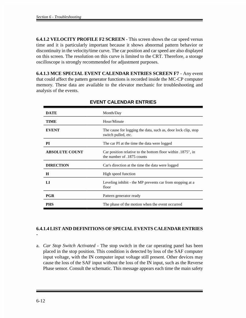
Section 6 - Troubleshooting
6-12
6.4.1.2 VELOCITY PROFILE F2 SCREEN - This screen shows the car speed versustime and it is particularly important because it shows abnormal pattern behavior ordiscontinuity in the velocity/time curve. The car position and car speed are also displayedon this screen. The resolution on this curve is limited to the CRT. Therefore, a storageoscilloscope is strongly recommended for adjustment purposes.
6.4.1.3 MCE SPECIAL EVENT CALENDAR ENTRIES SCREEN F7 - Any eventthat could affect the pattern generator functions is recorded inside the MC-CP computermemory. These data are available to the elevator mechanic for troubleshooting andanalysis of the events.
EVENT CALENDAR ENTRIES
DATE Month/Day
TIME Hour/Minute
EVENT The cause for logging the data, such as, door lock clip, stopswitch pulled, etc.
PI The car PI at the time the data were logged
ABSOLUTE COUNT Car position relative to the bottom floor within .1875", inthe number of .1875 counts
DIRECTION Car's direction at the time the data were logged
H High speed function
LI Leveling inhibit - the MP prevents car from stopping at afloor
PGR Pattern generator ready
PHS The phase of the motion when the event occurred
6.4.1.4 LIST AND DEFINITIONS OF SPECIAL EVENTS CALENDAR ENTRIES-
a. Car Stop Switch Activated - The stop switch in the car operating panel has beenplaced in the stop position. This condition is detected by loss of the SAF computerinput voltage, with the IN computer input voltage still present. Other devices maycause the loss of the SAF input without the loss of the IN input, such as the ReversePhase sensor. Consult the schematic. This message appears each time the main safety
Section 6 - Troubleshooting
6-13
circuit is restored and each time the main power is turned on because the main safetyrelays have a time delay when the power is turned on.
b. Correction Run - The IMC-DDP computer's pattern generator I/O subsystem receiveda UPG or DPG direction input as a result of the car initiating movement anywhereother than at a landing. Moving the car away from a landing while on inspection, andthen placing the car in normal operation, results in a correction run.
c. H and DIR W/O PG Ready - The IMC-DDP computer's pattern generator I/Osubsystem has its H (high speed) and UPG or DPG (up or down direction) inputs on,while the IMC-DDP computer is not ready to make a normal run (i.e., it does nothave its PG Ready flag on). This can occur when the pattern generator I/O Subsystemloses the UPG or DPG input temporarily during a normal run.
d. Terminal Slowdown - As the car approaches a terminal landing, the IMC-GIOcomputer detects a higher than normal or learned velocity at the time the contactopens on one of the ULSx or DLSx terminal landing limit switches (or contacts onthe TM switch). If a message appears on the F7 screen, see that the IMC-GIO boardhas completed or relearned the learning process if parameters on the F1 screen (shiftF2 for simplex) were modified. Also, see that the IMC-GIO board has stored avelocity value for each ULSx or DLSx limit switch in the hoistway. If velocityfluctuations are suspected approaching a terminal landing, go through the learnprocess several times and record the learned velocities in each case. If the velocityvaries by more than 5%, limit switches and roller guides should be checked.
e. Inspection/Access Activated - The Car Top Inspection, Relay Panel Inspection or In-Car Inspection switch is activated. There is no power on the IN input to the MC-MPcomputer.
f. Loss of Direction - The direction input (UPG or DPG) to the IMC-DDP computer hasbeen lost during a normal run. Check to see that when U1 and U2 relays are picked,the PD, UA1 and UA2 relays are also picked. If D1 and D2 relays are picked, PD,DA1 and DA2 relays must be picked. UA1, UA2, DA1 and DA2 relays must notbuzz when energized. If they do, replace the relay or interchange the buzzing relaywith one from position INX or L on the IMC-RB board.
g. Lost DLK in Phase 1-6 - The DLK input to the MC-MP computer has been lost
during a normal run. The hoistway door locks may have been clipped while the carwas passing a floor.
h. Main Safety String Open - The safety input (SAF) and the inspection/access (IN)input to MC-MP computer were both lost simultaneously as a result of one of the

Section 6 - Troubleshooting
6-14
devices in the main safety string opening up. Restoring the safety circuit to normalcauses the Car Stop Switch Activated message to appear.
i. Motor Limit Timer - The Motor Limit Timer has elapsed before the car has completedits movement. This condition can occur because the MC-MP computer receives adirection sensing (UPS or DNS) input for a sufficiently long time to cause the MLTtimer to elapse. This usually happens because of a failure in the system to respond toa 120VAC direction signal appearing on terminals 85 (up) or 87 (down) on the HC-RB relay board. Several things can cause this. There could be problems in UA1,UA2, DA1, DA2, PD, P and H relays. Contact closure must occur between terminals8X and 9X, or 7X and 9X, on the VVC-2-G drive unit. A speed pattern signal mustexist on terminal 10X with respect to 9X on the VVC-2-G drive unit. The speedpattern signal originates on terminal PATT with respect to terminal COM on theIMC-GIO board. If this message occurs after a Terminal Slowdown, make sure thereis a DC voltage between terminals 10X and 9X on the VVC-2-G terminal strip whendirection is picked and the IMC-GIO safety board is tripped. If there is no voltage,or the voltage is too low, adjust the Safety Voltage Adj trimpot on the IMC-GIOboard to achieve the appropriate voltage to make the car travel at leveling speed. Thisvoltage is measured between test points Safety PATT and COM on the IMC-GIOboard.
j. Motor Limit Timer (LI) - The Motor Limit Timer has elapsed before the carcompleted its movement, and the LI flag on the F3 screen was set. If the LI (LevelInhibit) flag is set, the car is prevented from recognizing the leveling and door zoneinputs, so it cannot stop at a floor. It is the LI flag, not response to a direction input,that is the problem.
k. Motor Limit Timer (INT) - The Motor Limit Timer has elapsed before the car hascompleted its movement, and, in addition, the INT (Level Interrupt) relay wasenergized. If the INT relay is picked, it prevents the car from recognizing the levelinginputs, thus preventing the car from stopping at a floor. So it is the fact that the INTis picked that is the problem, not failure to respond to a direction input.
l. Motor Limit Timer (LI INT) - The Motor Limit Timer has elapsed before the car hascompleted its movement, the INT (Level Interrupt) relay was energized, and the LIflag on the F3 screen was set. Both of the previous conditions are in effect.
m. OLM Position Counter Error - While the car was traveling in normal operation, theIMC-DDP computer detected a difference between the actual distance required toreach the destination and the learned distance. This condition is detected at 12" fromthe floor at the Outer Leveling Marker (OLM). It can occur as a result of adisturbance of the quadrature signal (DP1, DP2). The DP1 and DP2 quadrature

Section 6 - Troubleshooting
6-15
signals must be routed through shielded cable over the entire distance from the cartop to where the signal enters the IMC-RB board.
n. Pattern Modified at OLM - The IMC-DDP computer has modified the velocity profilebecause of a change in pattern voltage. This is an internally detected condition, andshould not be a cause for concern unless it occurs frequently.
o. DDP Power On/Reset - The IMC-DDP computer reset button has been pressed or the5V supply to the computer system has been turned off and on.
p. Releveling - The car has overshot/undershot the floor. This message occurs when acar comes to a stop at a floor too quickly, and requires a relevel operation into thefloor.
q. Quadrature Pulse Relation - The IMC-DDP computer has lost the quadrature signalfrom the car top landing system while the car was making a normal run. Allconnections between terminals 95 and 96 on the landing system and terminals 95 and96 on the controller should be intact and in a shielded cable.
6.4.1.5 LIMITS OF MOTION PARAMETERS - If the parameters describing thedynamic motion of the pattern generator are not within permissible boundaries, an errormessage appears on the F1 and F3 screens of the CRT. On the F1 screen (shift F2 forsimplex), the error message is, This Combination Of Parameter Values Is Unacceptable.On the F3 screen, IPE indicates this error message. The specific cause of the errorcondition is determined by the error flags at address 27H on the Pattern GeneratorDiagnostic Indicators. See Figure 5.6. A list of corrective actions for these error flags areas follows.
IP0: This is a STEP generation error. First, reduce jerks J1, J35 and J7. If this failsto remove the error condition, increase jerks J1, J35, and J7 and decreaseaccelerations A0, A2, and A6.
IP1: An unacceptable short floor has been detected.
IP2: The system is unable to generate a pattern for a two floor run. Increase jerksJ1, J35 and J7 or decrease accelerations A0, A2 and A6.
IP3: The intermediate leveling speed is too low. Increase VIL.
IP4: Phase 7 is too long. Decrease DFL and DL, or increase J7.
IP5: The jerk values are too small. Increase the smallest jerk value (J1, J35 or J7).
Section 6 - Troubleshooting
6-16
6.5.2 AUTO RESET FEATURE - The SCR drive automatically resets if a temporarypower outage occurs. This could happen when power is transferred from emergencypower back to commercial power in an instance where an emergency power generatorwas used. Since the transfer is usually very rapid and the phase sequence of theemergency generator may not match the phasing of the commercial power, the SCR driveinterprets the transfer from emergency to commercial power as a line fault, and the autoreset circuit resets the drive. The circuit monitors the Ready line on the HC-SCR board.If this signal goes low the auto reset generates a reset pulse in about fourteen seconds.Subsequent resetting of the drive is inhibited for 60 seconds after each reset pulse.
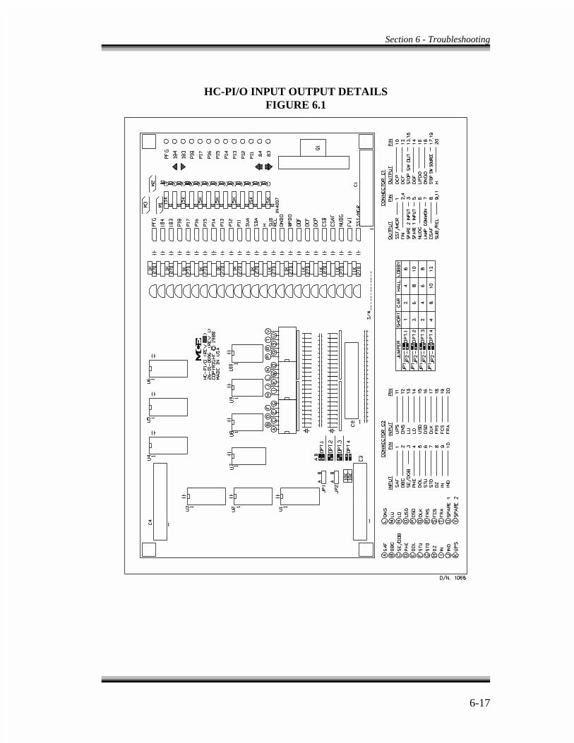
Section 6 - Troubleshooting
6-17
HC-PI/O INPUT OUTPUT DETAILSFIGURE 6.1

Section 6 - Troubleshooting
6-18
HC-RB RELAY BOARD DETAILFIGURE 6.2
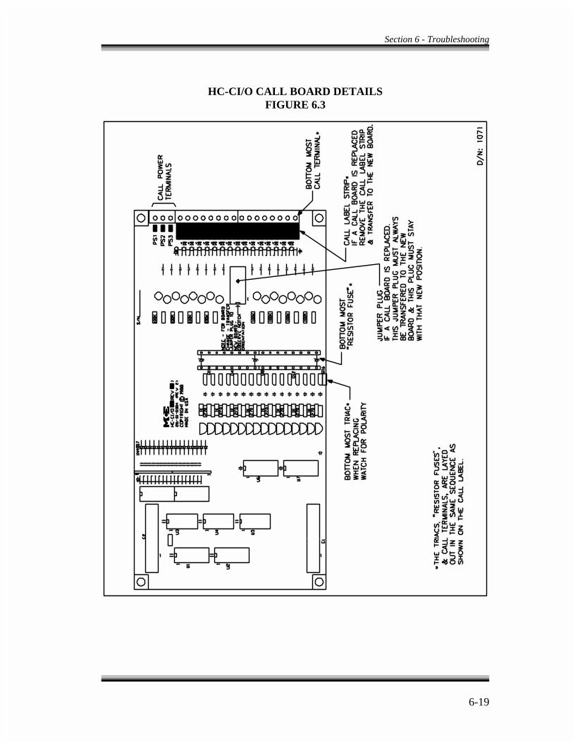
Section 6 - Troubleshooting
6-19
HC-CI/O CALL BOARD DETAILSFIGURE 6.3


SECTION - 7
JOB PRINTS

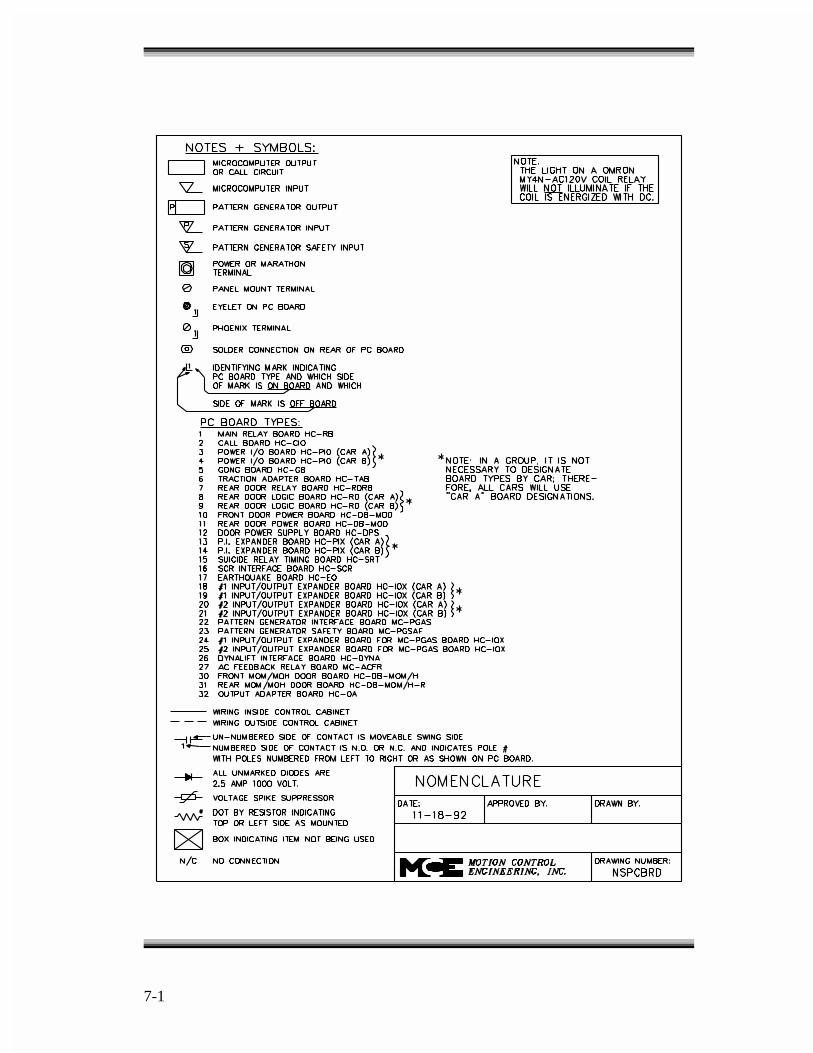
7-1
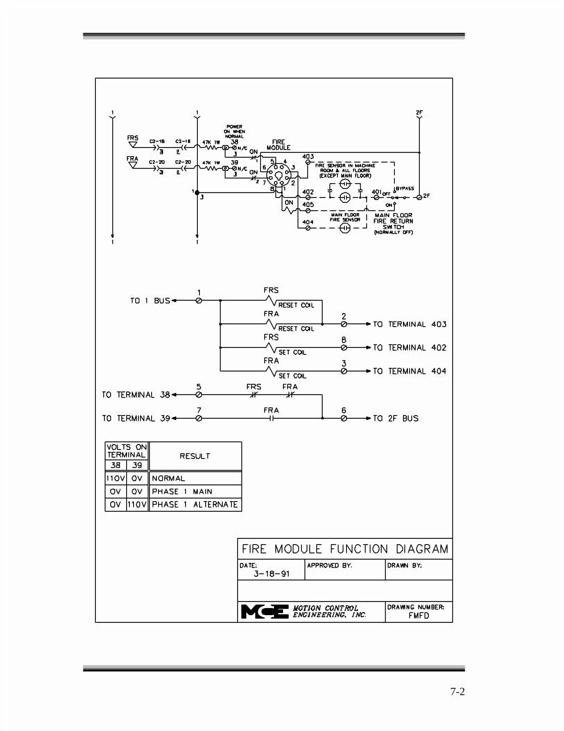
7-2
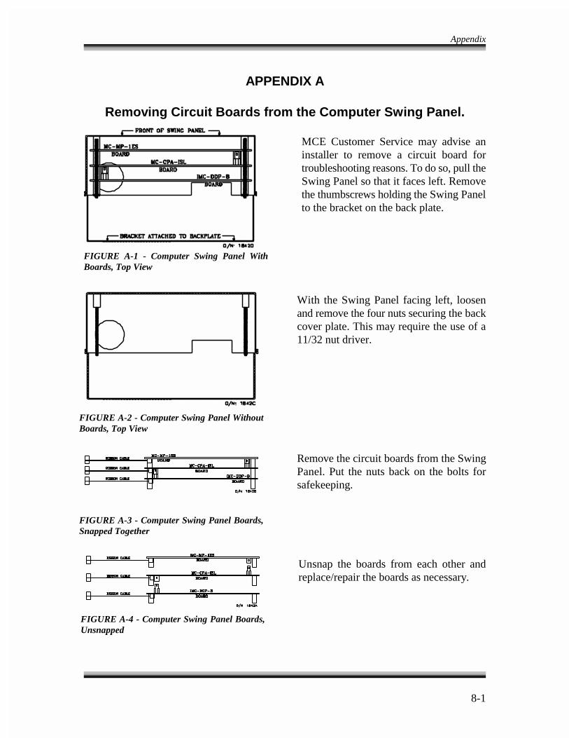
Appendix
8-1
FIGURE A-1 - Computer Swing Panel WithBoards, Top View
FIGURE A-2 - Computer Swing Panel WithoutBoards, Top View
FIGURE A-3 - Computer Swing Panel Boards,Snapped Together
FIGURE A-4 - Computer Swing Panel Boards,Unsnapped
APPENDIX A
Removing Circuit Boards from the Computer Swing Panel.
MCE Customer Service may advise aninstaller to remove a circuit board fortroubleshooting reasons. To do so, pull theSwing Panel so that it faces left. Removethe thumbscrews holding the Swing Panelto the bracket on the back plate.
With the Swing Panel facing left, loosenand remove the four nuts securing the backcover plate. This may require the use of a11/32 nut driver.
Remove the circuit boards from the SwingPanel. Put the nuts back on the bolts forsafekeeping.
Unsnap the boards from each other andreplace/repair the boards as necessary.

Appendix
8-2
APPENDIX B
ELEVATOR SECURITY INFORMATION AND OPERATION
Building name:
Building location:
Security activation: Key switch Mon: from to or
Time clock Tue: from to
Wed: from to
Thu: from to
Fri: from to
Sat: from to
Sun: from to
Instructions: To gain access to secure floors, follow the steps below while in the elevator car. The steps maybe taken while the elevator car is moving or standing still. Requests for an elevator car from a hallway orcorridor are answered without restriction.
1. While in the car, press the button for the desired floor. If the destination floor is secured, the button forthat floor will flash on/off.
If the button for that floor stays solidly lit, that floor is unsecured.
2. While the destination floor button is flashing, enter the security code for that floor within ten seconds.Enter the security code by pressing the corresponding buttons on the panel.
If the code was entered correctly and within the required time limit, the car will immediately go to thatfloor. If the code was not entered within the ten second time period or was entered incorrectly, thedestination floor button light will turn off after ten seconds and the entire sequence must be started overagain.
If a mistake is made while entering the security code, simply wait until the destination floor button lightstops flashing and start the entire sequence over again.
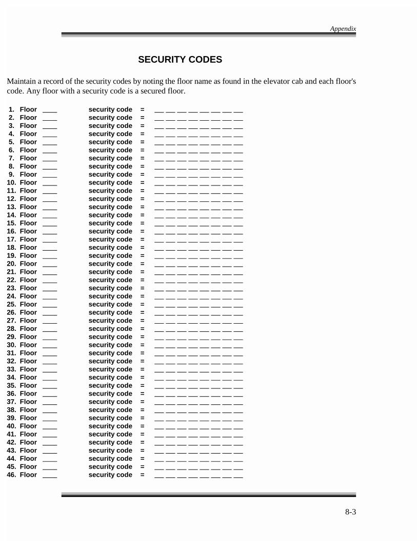
Appendix
8-3
SECURITY CODES
Maintain a record of the security codes by noting the floor name as found in the elevator cab and each floor'scode. Any floor with a security code is a secured floor.
1. Floor security code = 2. Floor security code = 3. Floor security code = 4. Floor security code = 5. Floor security code = 6. Floor security code = 7. Floor security code = 8. Floor security code = 9. Floor security code = 10. Floor security code = 11. Floor security code = 12. Floor security code = 13. Floor security code = 14. Floor security code = 15. Floor security code = 16. Floor security code = 17. Floor security code = 18. Floor security code = 19. Floor security code = 20. Floor security code = 21. Floor security code = 22. Floor security code = 23. Floor security code = 24. Floor security code = 25. Floor security code = 26. Floor security code = 27. Floor security code = 28. Floor security code = 29. Floor security code = 30. Floor security code = 31. Floor security code = 32. Floor security code = 33. Floor security code = 34. Floor security code = 35. Floor security code = 36. Floor security code = 37. Floor security code = 38. Floor security code = 39. Floor security code = 40. Floor security code = 41. Floor security code = 42. Floor security code = 43. Floor security code = 44. Floor security code = 45. Floor security code = 46. Floor security code =

Appendix
8-4
APPENDIX CINSTRUCTIONS FOR CHANGING EPROMS
AND MICROCONTROLLERS
With direction from MCE Customer Service, the computer chips may need to be reinstalled in the field. Greatcare should be taken when changing an EPROM or microcontroller. The EPROM stores the computerprogram, and the microcontroller both stores and executes the program. These instructions should be followedstep by step.
REPLACING AN EPROM
1. Turn off main power at the disconnect and verify that no lights are operating on the Swing Panel.
2. Take the back cover off of the Swing Panel, exposing the processor board assembly. Remove the boardset from the Swing Panel. Refer to Appendix A for instructions on unloading the boards from the SwingPanel.
3. The three boards within the assembly contain one EPROM chip each for the MC-MP and MC-CP boards,and two EPROMs for the IMC-DDP board. The EPROM is a rectangular component that has a small glasswindow on its top, and is usually covered by a silver or white paper tag. Refer to Figures C.1, C.2 and C.3of this section for the location of the EPROM on each board.
4. The label on each EPROM indicates the board to which it belongs. The EPROM labeled S-MP-xx-1should be installed in the MC-MP board. The EPROM labeled S-CP-xx-1 should be installed in theMC-CP board. The EPROMs labeled S-DDP-P-1 and S-DDP-P-2 should be installed in the IMC-DDPboard. Determine which board requires the EPROM change.
5. Using a small, thin bladed screwdriver, place the tip between the EPROM chip and its socket, not betweenthe socket and the board. Gently pry the existing EPROM out from the microprocessor board. Do this veryslowly, taking care not to bend the leads that come out of the socket. If they bend, straighten them slowlyand carefully with a pair of needlenose pliers.
6. Place the new EPROM lightly (do not plug it in yet) into the socket and check to see that all pins arealigned with their corresponding holes in the socket. Also make sure that the notch on the end of theEPROM is aligned with the notch on the socket (the orientation of the notch should also correspond tothe notches on all of the other chips on the board). Now push the EPROM firmly into the socket and makesure that none of the pins are bent during the insertion. Inspect the EPROM to make sure that no pins arebent outward or under the EPROM.
7. Reassemble the Swing Panel assembly and close the Swing Panel. Refer to Appendix A for a descriptionof the basic structure of the three-board set.
8. Reapply power to the system. Verify the proper operation of all boards by inspecting the diagnosticindicators on the individual processor boards.

Appendix
8-5
9. If, after turning on the system, the Computer On LEDs are not illuminated on all three boards, the EPROMmay not have been installed properly. Repeat steps 1 through 8.
MICROCONTROLLER INSTRUCTIONS
1. Turn off the main power at the disconnect and verify that no lights or LEDs are operating on the SwingPanel.
2. Refer to Figure C.4 of this section for the location of the microcontroller on the IMC-GIO board. Usinga small, thin bladed screwdriver, place the tip of the screwdriver between the microcontroller chip and itssocket, not between the socket and the board. Gently pry the microcontroller chip from its socket. Do thisslowly, taking care not to bend the last pins as they come out of the socket.
3. Place the new microcontroller lightly (do not plug it in yet) into the socket and check that all pins arealigned with their corresponding holes in the socket. Also, make sure that the notch on the end of themicrocontroller is correctly aligned with the notch on the socket. The orientation of the notch shouldcorrespond with the notches on all the other chips on the board. Now push the microcontroller firmly intothe socket and make sure that none of the pins are bent outward or under the microcontroller.
4. Reapply power to the system. Verify the proper operation of the IMC-GIO board by observing the TEST
and PASS messages on the four character Alphanumeric Display.
5. If, after turning on the system, the TEST and PASS messages do not appear, the microcontroller may nothave been installed properly. Repeat steps one through four.

Appendix
8-6
FIGURE C.1 - EPROM Location on Main Processor Board (MC-MP)
FIGURE C.2 - EPROM on Communication Processor Board (MC-CP)
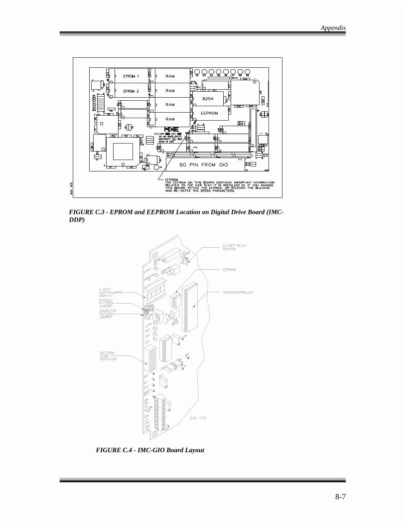
Appendix
8-7
FIGURE C.3 - EPROM and EEPROM Location on Digital Drive Board (IMC-DDP)
FIGURE C.4 - IMC-GIO Board Layout
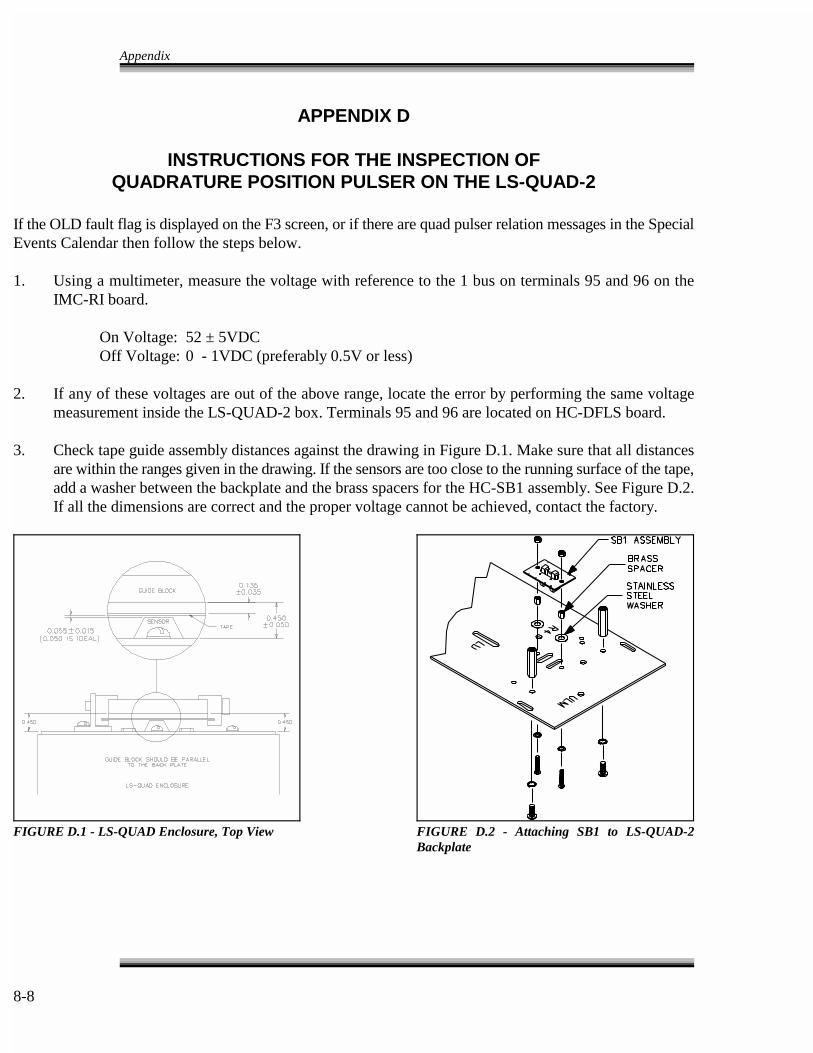
Appendix
8-8
FIGURE D.1 - LS-QUAD Enclosure, Top View FIGURE D.2 - Attaching SB1 to LS-QUAD-2Backplate
APPENDIX D
INSTRUCTIONS FOR THE INSPECTION OFQUADRATURE POSITION PULSER ON THE LS-QUAD-2
If the OLD fault flag is displayed on the F3 screen, or if there are quad pulser relation messages in the SpecialEvents Calendar then follow the steps below.
1. Using a multimeter, measure the voltage with reference to the 1 bus on terminals 95 and 96 on theIMC-RI board.
On Voltage: 52 ± 5VDC Off Voltage: 0 - 1VDC (preferably 0.5V or less)
2. If any of these voltages are out of the above range, locate the error by performing the same voltagemeasurement inside the LS-QUAD-2 box. Terminals 95 and 96 are located on HC-DFLS board.
3. Check tape guide assembly distances against the drawing in Figure D.1. Make sure that all distancesare within the ranges given in the drawing. If the sensors are too close to the running surface of the tape,add a washer between the backplate and the brass spacers for the HC-SB1 assembly. See Figure D.2.If all the dimensions are correct and the proper voltage cannot be achieved, contact the factory.
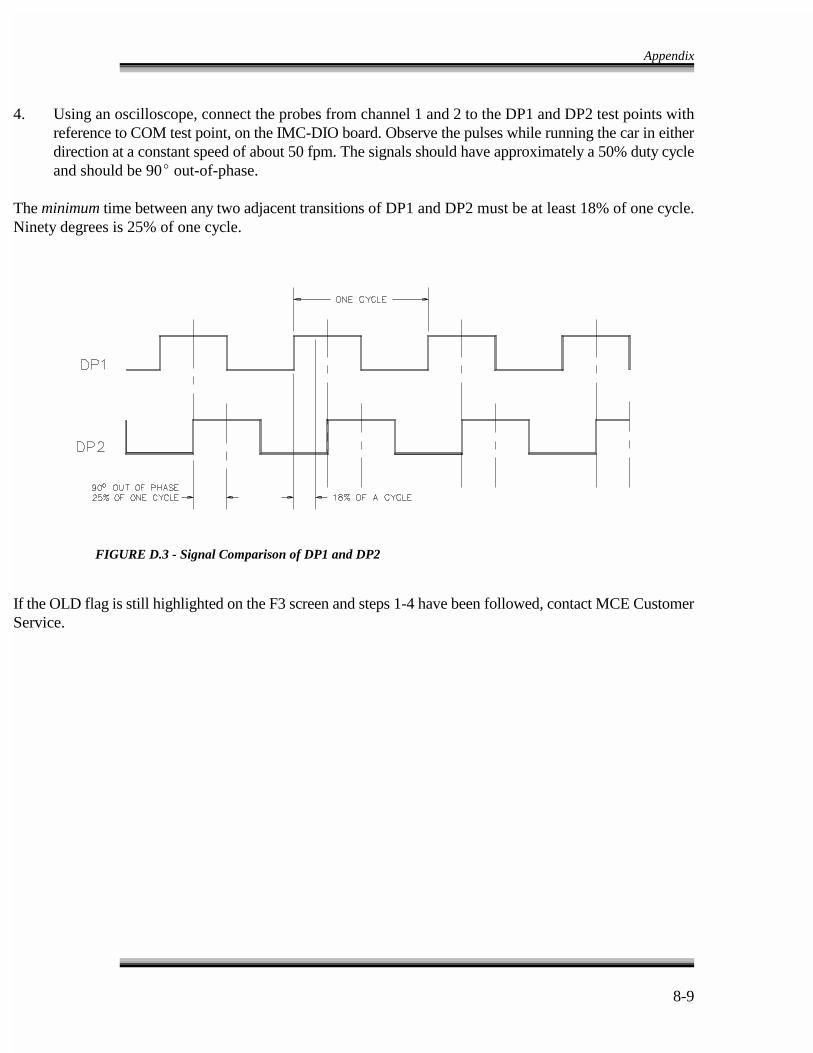
Appendix
8-9
FIGURE D.3 - Signal Comparison of DP1 and DP2
4. Using an oscilloscope, connect the probes from channel 1 and 2 to the DP1 and DP2 test points withreference to COM test point, on the IMC-DIO board. Observe the pulses while running the car in eitherdirection at a constant speed of about 50 fpm. The signals should have approximately a 50% duty cycleand should be 90� out-of-phase.
The minimum time between any two adjacent transitions of DP1 and DP2 must be at least 18% of one cycle.Ninety degrees is 25% of one cycle.
If the OLD flag is still highlighted on the F3 screen and steps 1-4 have been followed, contact MCE CustomerService.
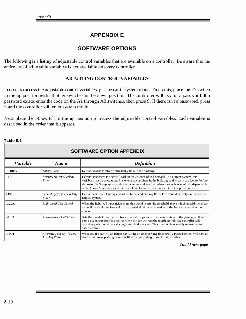
Appendix
8-10
APPENDIX E
SOFTWARE OPTIONS
The following is a listing of adjustable control variables that are available on a controller. Be aware that theentire list of adjustable variables is not available on every controller.
ADJUSTING CONTROL VARIABLES
In order to access the adjustable control variables, put the car in system mode. To do this, place the F7 switchin the up position with all other switches in the down position. The controller will ask for a password. If apassword exists, enter the code on the A1 through A8 switches, then press S. If there isn't a password, pressS and the controller will enter system mode.
Next place the F6 switch in the up position to access the adjustable control variables. Each variable isdescribed in the order that it appears.
Table E.1
SOFTWARE OPTION APPENDIX
Variable Name Definition
LOBBY Lobby Floor Determines the location of the lobby floor in the building.
PPF Primary (lower) Parking Determines where the car will park in the absence of call demand. In a Duplex system, thisFloor variable must be programmed as one of the landings in the building, and is set at the factory before
shipment. In Group systems, this variable only takes effect when the car is operating independentlyof the Group Supervisor or if there is a loss of communication with the Group Supervisor.
SPF Secondary (upper) Parking Determines which landing is used as the second parking floor. This variable is only available on aFloor Duplex system.
LLCC Light Load Call Cancel When the light load input (LLI) is on, this variable sets the threshold above which an additional carcall will cause all previous calls to be canceled with the exception of the last call entered in thesystem.
PECC Anti-nuisance Call Cancel Sets the threshold for the number of car call stops without an interruption of the photo-eye. If nophoto-eye interruption is detected when the car answers the fourth car call, the controller willcancel any additional car calls registered in the system. This function is normally referred to asanti-nuisance.
APP1 Alternate Primary (lower) When on, the car will no longer park at the original parking floor (PPF). Instead the car will park atParking Floor the first alternate parking floor specified by the landing stored in this variable.
Cont'd next page
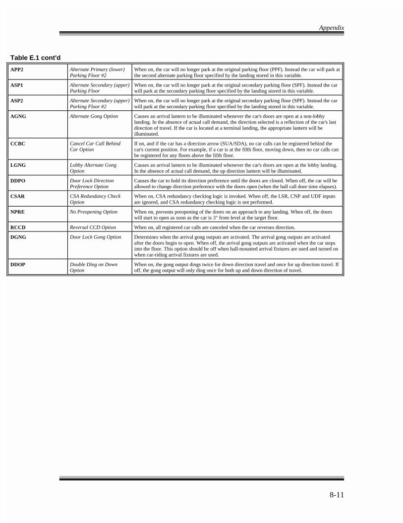
Appendix
8-11
Table E.1 cont'd
APP2 Alternate Primary (lower) When on, the car will no longer park at the original parking floor (PPF). Instead the car will park atParking Floor #2 the second alternate parking floor specified by the landing stored in this variable.
ASP1 Alternate Secondary (upper) When on, the car will no longer park at the original secondary parking floor (SPF). Instead the carParking Floor will park at the secondary parking floor specified by the landing stored in this variable.
ASP2 Alternate Secondary (upper) When on, the car will no longer park at the original secondary parking floor (SPF). Instead the carParking Floor #2 will park at the secondary parking floor specified by the landing stored in this variable.
AGNG Alternate Gong Option Causes an arrival lantern to be illuminated whenever the car's doors are open at a non-lobbylanding. In the absence of actual call demand, the direction selected is a reflection of the car's lastdirection of travel. If the car is located at a terminal landing, the appropriate lantern will beilluminated.
CCBC Cancel Car Call Behind If on, and if the car has a direction arrow (SUA/SDA), no car calls can be registered behind theCar Option car's current position. For example, if a car is at the fifth floor, moving down, then no car calls can
be registered for any floors above the fifth floor.
LGNG Lobby Alternate Gong Causes an arrival lantern to be illuminated whenever the car's doors are open at the lobby landing.Option In the absence of actual call demand, the up direction lantern will be illuminated.
DDPO Door Lock Direction Causes the car to hold its direction preference until the doors are closed. When off, the car will bePreference Option allowed to change direction preference with the doors open (when the hall call door time elapses).
CSAR CSA Redundancy Check When on, CSA redundancy checking logic is invoked. When off, the LSR, CNP and UDF inputsOption are ignored, and CSA redundancy checking logic is not performed.
NPRE No Preopening Option When on, prevents preopening of the doors on an approach to any landing. When off, the doorswill start to open as soon as the car is 3" from level at the target floor.
RCCD Reversal CCD Option When on, all registered car calls are canceled when the car reverses direction.
DGNG Door Lock Gong Option Determines when the arrival gong outputs are activated. The arrival gong outputs are activatedafter the doors begin to open. When off, the arrival gong outputs are activated when the car stepsinto the floor. This option should be off when hall-mounted arrival fixtures are used and turned onwhen car-riding arrival fixtures are used.
DDOP Double Ding on Down When on, the gong output dings twice for down direction travel and once for up direction travel. IfOption off, the gong output will only ding once for both up and down direction of travel.