motion control engineering, inc. · motion control engineering, inc. 11380 white rock road rancho...
TRANSCRIPT

MOTION CONTROL ENGINEERING, INC.11380 WHITE ROCK ROAD
RANCHO CORDOVA, CA 95742TELEPHONE (916) 463-9200 FAX (916) 463-9201
CONTROLLER INSTALLATION MANUAL
HMC-1000 HYDRAULIC CONTROLLER
PART # 42-02-1020 REV. D.9 OCTOBER 2006
This manual is for HMC-1000Controllers with Release 4 software

42-02-1020 TABLE OF CONTENTS • i
TABLE OF CONTENTS
IMPORTANT NOTES & PRECAUTIONS . . . . . . . . . . . . . . . . . . . . . . . . . . . . . . . . . . vii
SECTION 1PRODUCT DESCRIPTION
1.0 General Information . . . . . . . . . . . . . . . . . . . . . . . . . . . . . . . . . . . . . . . . . . . . . . . 1-1
1.1 Car Controller Description . . . . . . . . . . . . . . . . . . . . . . . . . . . . . . . . . . . . . . . . . . 1-2
1.2 Car Controller Functional Layout . . . . . . . . . . . . . . . . . . . . . . . . . . . . . . . . . . . . . 1-8
1.2.1 Car Operation Control (COC) . . . . . . . . . . . . . . . . . . . . . . . . . . . . . . . . . . 1-81.2.2 Car Communications Control (CCC) . . . . . . . . . . . . . . . . . . . . . . . . . . . . 1-101.2.3 Car Power Control (CPC) . . . . . . . . . . . . . . . . . . . . . . . . . . . . . . . . . . . . 1-11
1.3 Landing System Control Box . . . . . . . . . . . . . . . . . . . . . . . . . . . . . . . . . . . . . . . 1-11
1.4 Diagnostic Tools and Peripherals . . . . . . . . . . . . . . . . . . . . . . . . . . . . . . . . . . . . 1-12
1.5 Group Supervisor (2 or More Cars) . . . . . . . . . . . . . . . . . . . . . . . . . . . . . . . . . . 1-12
SECTION 2INSTALLATION
2.0 General Information . . . . . . . . . . . . . . . . . . . . . . . . . . . . . . . . . . . . . . . . . . . . . . . 2-1
2.0.1 Site Selection . . . . . . . . . . . . . . . . . . . . . . . . . . . . . . . . . . . . . . . . . . . . . . 2-12.0.2 Environmental Considerations . . . . . . . . . . . . . . . . . . . . . . . . . . . . . . . . . 2-12.0.3 Recommended Tools and Test Equipment . . . . . . . . . . . . . . . . . . . . . . . . 2-22.0.4 The Wiring Prints . . . . . . . . . . . . . . . . . . . . . . . . . . . . . . . . . . . . . . . . . . . 2-2
2.1 Controller Installation . . . . . . . . . . . . . . . . . . . . . . . . . . . . . . . . . . . . . . . . . . . . . . 2-3
2.1.1 Controller Wiring Guidelines . . . . . . . . . . . . . . . . . . . . . . . . . . . . . . . . . . . 2-3
2.2 General Wiring Guidelines . . . . . . . . . . . . . . . . . . . . . . . . . . . . . . . . . . . . . . . . . . 2-4
2.2.1 Ground Wiring . . . . . . . . . . . . . . . . . . . . . . . . . . . . . . . . . . . . . . . . . . . . . 2-42.2.2 Main AC Power . . . . . . . . . . . . . . . . . . . . . . . . . . . . . . . . . . . . . . . . . . . . . 2-52.2.3 Pump Motor Wiring . . . . . . . . . . . . . . . . . . . . . . . . . . . . . . . . . . . . . . . . . . 2-5

• TABLE OF CONTENTS 42-02-1020ii
2.3 Hoistway Control Equipment Installation . . . . . . . . . . . . . . . . . . . . . . . . . . . . . . . 2-5
2.3.1 Installing the Landing System . . . . . . . . . . . . . . . . . . . . . . . . . . . . . . . . . . 2-52.3.2 Installing the Hoistway Limit Switches . . . . . . . . . . . . . . . . . . . . . . . . . . . 2-52.3.3 Installing the Landing System Control Box (LS-QUTE) . . . . . . . . . . . . . . . 2-62.3.4 Installing the Magnetic Strips on the Steel Tape . . . . . . . . . . . . . . . . . . . . 2-62.3.5 Door Position Monitor Switch (If Used) . . . . . . . . . . . . . . . . . . . . . . . . . . . 2-7
SECTION 3START-UP
3.0 General Information . . . . . . . . . . . . . . . . . . . . . . . . . . . . . . . . . . . . . . . . . . . . . . . 3-1
3.1 Ground Check . . . . . . . . . . . . . . . . . . . . . . . . . . . . . . . . . . . . . . . . . . . . . . . . . . . 3-1
3.2 Before Applying Power . . . . . . . . . . . . . . . . . . . . . . . . . . . . . . . . . . . . . . . . . . . . . 3-1
3.3 Applying Power . . . . . . . . . . . . . . . . . . . . . . . . . . . . . . . . . . . . . . . . . . . . . . . . . . 3-2
3.3.1 Initial Adjustments and Power Phasing . . . . . . . . . . . . . . . . . . . . . . . . . . . 3-23.3.2 Moving the Elevator on Inspection . . . . . . . . . . . . . . . . . . . . . . . . . . . . . . 3-33.3.3 Preparing the Car to Run on Automatic Operation . . . . . . . . . . . . . . . . . . 3-3
3.4 Preparation for Final Adjustment . . . . . . . . . . . . . . . . . . . . . . . . . . . . . . . . . . . . . 3-4
SECTION 4FINAL ADJUSTMENT
4.0 General Information . . . . . . . . . . . . . . . . . . . . . . . . . . . . . . . . . . . . . . . . . . . . . . . 4-1
4.1 Running on Automatic Operation . . . . . . . . . . . . . . . . . . . . . . . . . . . . . . . . . . . . . 4-1
4.1.1 Status and Diagnostic Indicators . . . . . . . . . . . . . . . . . . . . . . . . . . . . . . . 4-14.1.2 Absolute Floor Encoding . . . . . . . . . . . . . . . . . . . . . . . . . . . . . . . . . . . . . 4-24.1.3 Registering Car Calls . . . . . . . . . . . . . . . . . . . . . . . . . . . . . . . . . . . . . . . . 4-34.1.4 Test Mode Operation . . . . . . . . . . . . . . . . . . . . . . . . . . . . . . . . . . . . . . . . 4-34.1.5 Switching to Automatic Operation . . . . . . . . . . . . . . . . . . . . . . . . . . . . . . . 4-4
4.2 Final Adjustments . . . . . . . . . . . . . . . . . . . . . . . . . . . . . . . . . . . . . . . . . . . . . . . . 4-4
4.2.1 Door Operator Adjustments . . . . . . . . . . . . . . . . . . . . . . . . . . . . . . . . . . . 4-44.2.2 Hydraulic Valves . . . . . . . . . . . . . . . . . . . . . . . . . . . . . . . . . . . . . . . . . . . . 4-54.2.3 Slowdown and Limit Switches . . . . . . . . . . . . . . . . . . . . . . . . . . . . . . . . . . 4-54.2.4 Hall Calls . . . . . . . . . . . . . . . . . . . . . . . . . . . . . . . . . . . . . . . . . . . . . . . . . 4-54.2.5 Options . . . . . . . . . . . . . . . . . . . . . . . . . . . . . . . . . . . . . . . . . . . . . . . . . . . 4-54.2.6 Door Open/close Protection . . . . . . . . . . . . . . . . . . . . . . . . . . . . . . . . . . . 4-54.2.7 Motor Limit Timer . . . . . . . . . . . . . . . . . . . . . . . . . . . . . . . . . . . . . . . . . . . 4-54.2.8 Valve Limit Timer . . . . . . . . . . . . . . . . . . . . . . . . . . . . . . . . . . . . . . . . . . . 4-54.2.9 Stuck Button Protection . . . . . . . . . . . . . . . . . . . . . . . . . . . . . . . . . . . . . . 4-54.2.10 Relevel Operation . . . . . . . . . . . . . . . . . . . . . . . . . . . . . . . . . . . . . . . . . . . 4-5
4.3 Setting the Car Network ID . . . . . . . . . . . . . . . . . . . . . . . . . . . . . . . . . . . . . . . . . 4-6

42-02-1020 TABLE OF CONTENTS • iii
SECTION 5THE COMPUTER
5.0 General Information . . . . . . . . . . . . . . . . . . . . . . . . . . . . . . . . . . . . . . . . . . . . . . . 5-1
5.1 Enhanced Onboard Diagnostics (EOD) Overview . . . . . . . . . . . . . . . . . . . . . . . . 5-15.1.1 Description of Eod Lights and Switches . . . . . . . . . . . . . . . . . . . . . . . . . . 5-1
5.2 Normal Mode (EOD) . . . . . . . . . . . . . . . . . . . . . . . . . . . . . . . . . . . . . . . . . . . . . . 5-4
5.2.1 Alphanumeric Display (Default Displays) . . . . . . . . . . . . . . . . . . . . . . . . . 5-45.2.2 Diagnostic Indicators . . . . . . . . . . . . . . . . . . . . . . . . . . . . . . . . . . . . . . . . 5-65.2.3 Adjustment of the Elevator Timers . . . . . . . . . . . . . . . . . . . . . . . . . . . . . . 5-75.2.4 Setting the Real Time Clock . . . . . . . . . . . . . . . . . . . . . . . . . . . . . . . . . . . 5-95.2.5 Alphanumeric Display - Viewing the MP /MP2 Internal Flags / Inputs . . . . 5-95.2.6 Resetting the MC-CGP Parameters . . . . . . . . . . . . . . . . . . . . . . . . . . . . 5-10
5.3 System Mode (EOD) . . . . . . . . . . . . . . . . . . . . . . . . . . . . . . . . . . . . . . . . . . . . . 5-11
5.3.1 Programming the Communication Ports . . . . . . . . . . . . . . . . . . . . . . . . . 5-125.3.2 Viewing and Changing the Security Codes . . . . . . . . . . . . . . . . . . . . . . . 5-145.3.3 Setting MSK: Master Software Key . . . . . . . . . . . . . . . . . . . . . . . . . . . . . 5-165.3.4 Setting the Software Options - Adjustable Control Variables . . . . . . . . . 5-165.3.5 Load Weigher Learn Operation (Calibration) . . . . . . . . . . . . . . . . . . . . . 5-185.3.6 Setting and Resetting the Passcode Option (Not on All Controllers) . . . . 5-23
5.4 Diagnostic Mode (EOD) . . . . . . . . . . . . . . . . . . . . . . . . . . . . . . . . . . . . . . . . . . . 5-24
5.4.1 Viewing the MC-MP or MC-MP2 Computer Flags . . . . . . . . . . . . . . . . . . 5-245.4.2 Viewing and Entering Calls . . . . . . . . . . . . . . . . . . . . . . . . . . . . . . . . . . . 5-30
SECTION 6TROUBLESHOOTING
6.0 General Information . . . . . . . . . . . . . . . . . . . . . . . . . . . . . . . . . . . . . . . . . . . . . . . 6-1
6.1 Status and Error Messages . . . . . . . . . . . . . . . . . . . . . . . . . . . . . . . . . . . . . . . . . 6-2
6.1.1 Computer Swing Panel Status and Diagnostic Indicators . . . . . . . . . . . . . 6-26.1.2 MC-MP2 Diagnostic Indicators and Alphanumeric Display . . . . . . . . . . . . 6-46.1.3 Special Events Calendar Fault Log . . . . . . . . . . . . . . . . . . . . . . . . . . . . . . 6-76.1.4 View Hoistway (F3) Screen Fault Flags . . . . . . . . . . . . . . . . . . . . . . . . . . 6-86.1.5 Status and Error Messages Table . . . . . . . . . . . . . . . . . . . . . . . . . . . . . . 6-9
6.2 Using the Special Events Calendar . . . . . . . . . . . . . . . . . . . . . . . . . . . . . . . . . . 6-19
6.3 Using the Diagnostics . . . . . . . . . . . . . . . . . . . . . . . . . . . . . . . . . . . . . . . . . . . . 6-23
6.4 Troubleshooting Car Operation Control (COC) . . . . . . . . . . . . . . . . . . . . . . . . . 6-26
6.4.1 Door Logic . . . . . . . . . . . . . . . . . . . . . . . . . . . . . . . . . . . . . . . . . . . . . . . 6-266.4.2 Call Logic - Normal Operation . . . . . . . . . . . . . . . . . . . . . . . . . . . . . . . . . 6-326.4.3 Troubleshooting the Call Circuits . . . . . . . . . . . . . . . . . . . . . . . . . . . . . . 6-346.4.4 Troubleshooting the Call Indicators . . . . . . . . . . . . . . . . . . . . . . . . . . . . 6-35

• TABLE OF CONTENTS 42-02-1020iv
6.5 PC Board Quick References . . . . . . . . . . . . . . . . . . . . . . . . . . . . . . . . . . . . . . . 6-35
6.6 Using the MLT / VLT Data Trap . . . . . . . . . . . . . . . . . . . . . . . . . . . . . . . . . . . . . 6-41
APPENDIX
Appendix A Disassembling the Computer Swing Panel . . . . . . . . . . . . . . . . . . . . . . . . A-1
Appendix B Changing PC Boards or EPROMS . . . . . . . . . . . . . . . . . . . . . . . . . . . . . . A-2
B.1 Replacing the Main Processor Board or EPROM . . . . . . . . . . . . . A-2B.2 Replacing the MC-CGP-4(8) Board or EPROMS . . . . . . . . . . . . . A-3
Appendix C Nomenclature . . . . . . . . . . . . . . . . . . . . . . . . . . . . . . . . . . . . . . . . . . . . . . A-5
Appendix D Flex-Talk Option . . . . . . . . . . . . . . . . . . . . . . . . . . . . . . . . . . . . . . . . . . . . A-7
Appendix E LS-QUTE Landing System Assembly Drawings . . . . . . . . . . . . . . . . . . . A-10
INDEX
FIGURES
Figure 1.1 Typical Physical Layout . . . . . . . . . . . . . . . . . . . . . . . . . . . . . . . . . . . . . . 1-2Figure 1.2 Computer Swing Panel . . . . . . . . . . . . . . . . . . . . . . . . . . . . . . . . . . . . . . . 1-3Figure 1.3 MC-MP2 Main Processor Board . . . . . . . . . . . . . . . . . . . . . . . . . . . . . . . . 1-3Figure 1.4 MC-CGP-4 Communication Processor Board . . . . . . . . . . . . . . . . . . . . . . 1-4Figure 1.5 MC-RS Communication Interface Board . . . . . . . . . . . . . . . . . . . . . . . . . . 1-4Figure 1.6 HC-PI/O Power Input/Output Board . . . . . . . . . . . . . . . . . . . . . . . . . . . . . 1-5Figure 1.7 HC-PIX Position Indicator Expander Board . . . . . . . . . . . . . . . . . . . . . . . 1-5Figure 1.8 HC-CI/O Call Input/Output Board . . . . . . . . . . . . . . . . . . . . . . . . . . . . . . . 1-6Figure 1.9 HC-IOX Input/Output Expander Board . . . . . . . . . . . . . . . . . . . . . . . . . . . 1-6Figure 1.10 HC-I4O Input/Output Expander Board . . . . . . . . . . . . . . . . . . . . . . . . . . . 1-6Figure 1.11 HC-RBH Relay Board Layout . . . . . . . . . . . . . . . . . . . . . . . . . . . . . . . . . . 1-7Figure 1.12 Car Controller Functional Layout . . . . . . . . . . . . . . . . . . . . . . . . . . . . . . . 1-9Figure 1.13 LS-STAN Car Top Control Box . . . . . . . . . . . . . . . . . . . . . . . . . . . . . . . . 1-11Figure 1.14 LS-QUTE Car Top Control Box . . . . . . . . . . . . . . . . . . . . . . . . . . . . . . . 1-11Figure 2.1 Ground Wiring to Controller Cabinets . . . . . . . . . . . . . . . . . . . . . . . . . . . . 2-5Figure 2.2 SLA Series Phase Monitor Wiring Diagrams . . . . . . . . . . . . . . . . . . . . . . 2-6Figure 5.1 Computer Swing Panel, Front View . . . . . . . . . . . . . . . . . . . . . . . . . . . . . 5-2Figure 5.2 Computer Swing Panel (Back Plate) . . . . . . . . . . . . . . . . . . . . . . . . . . . . 5-3Figure 5.3 Viewing the flags at Address 20H (from Table 5.10) . . . . . . . . . . . . . . . 5-20Figure 5.4 Viewing and Entering Hall & Car Calls via the EOD . . . . . . . . . . . . . . . . 5-21Figure 6.1 Computer Swing Panel, Front View . . . . . . . . . . . . . . . . . . . . . . . . . . . . . 6-2Figure 6.2 Special Events Calendar (F7 - 1) screen . . . . . . . . . . . . . . . . . . . . . . . . . 6-7Figure 6.3 View Hoistway (F3) Screen . . . . . . . . . . . . . . . . . . . . . . . . . . . . . . . . . . . 6-8Figure 6.4 Legend for Table 6.4, Status and Error Messages . . . . . . . . . . . . . . . . . . 6-9Figure 6.5 Special Events Calendar Menu (F7) screen . . . . . . . . . . . . . . . . . . . . . . 6-19Figure 6.6 Special Events Calendar (F7 - 1) screen . . . . . . . . . . . . . . . . . . . . . . . . 6-20
42-02-1020 TABLE OF CONTENTS • v
Figure 6.7 Special Events Calendar Troubleshooting (F7 - 1 - Crtl +T) screen . . . . 6-20Figure 6.8 Special Events - Configure by Type (F7, 3) screen . . . . . . . . . . . . . . . . . 6-21Figure 6.9 Special Events - Configure by Type - Event Description (F7, 3) screen . 6-22Figure 6.10 Special Events - Print Events (F7, 8) screen . . . . . . . . . . . . . . . . . . . . . . 6-22Figure 6.11 Diagnostics Menu (F11) screen . . . . . . . . . . . . . . . . . . . . . . . . . . . . . . . 6-23Figure 6.12 Network Status (F11, 1) screen . . . . . . . . . . . . . . . . . . . . . . . . . . . . . . . 6-23Figure 6.13 MP2 Input/Output (F11,7) screen . . . . . . . . . . . . . . . . . . . . . . . . . . . . . . 6-24Figure 6.14 Car Performance Graph (F11, 8) screen . . . . . . . . . . . . . . . . . . . . . . . . 6-25Figure 6.15 Car Performance Report (F11, 8, H) screen . . . . . . . . . . . . . . . . . . . . . . 6-25Figure 6.16 Door Sequence of Operation Flowchart . . . . . . . . . . . . . . . . . . . . . . . . . 6-28Figure 6.17 HC-PI/O Power Input/Output Board Quick Reference . . . . . . . . . . . . . . 6-30Figure 6.18 HC-RBH Relay Board Details . . . . . . . . . . . . . . . . . . . . . . . . . . . . . . . . . 6-31Figure 6.19 HC-CI/O Call Input/Output Board Quick Reference . . . . . . . . . . . . . . . . 6-33Figure 6.20 MC-MP-1ES Main Processor Board Quick Reference . . . . . . . . . . . . . . 6-36Figure 6.21 MC-MP2 Main Processor Board Quick Reference . . . . . . . . . . . . . . . . . 6-37Figure 6.22 MC-CGP-4 Communication Processor Board Quick Reference . . . . . . . 6-38Figure 6.23 MC-RS Communication Interface Board Quick Reference . . . . . . . . . . . 6-39Figure 6.24 HC-IPLS IP Landing System Board Quick Reference . . . . . . . . . . . . . . . 6-40Figure 6.25 Standard Board Layout . . . . . . . . . . . . . . . . . . . . . . . . . . . . . . . . . . . . . . 6-41Figure A.1 Computer Swing Panel Boards, Unsnapped . . . . . . . . . . . . . . . . . . . . . . . A-1Figure A.2 Computer Swing Panel Boards, Snapped Together . . . . . . . . . . . . . . . . . A-1Figure A.3 Computer Swing Panel Without Boards (Top View) . . . . . . . . . . . . . . . . . A-1Figure A.4 Computer Swing Panel With Boards (Top View) . . . . . . . . . . . . . . . . . . . . A-1Figure D.1 TPI-FT Flex-Talk Board . . . . . . . . . . . . . . . . . . . . . . . . . . . . . . . . . . . . . . A-7Figure D.2 Diagnostic Table . . . . . . . . . . . . . . . . . . . . . . . . . . . . . . . . . . . . . . . . . . . . A-8Figure D.3 Speaker Dimensions . . . . . . . . . . . . . . . . . . . . . . . . . . . . . . . . . . . . . . . . . A-9Figure E.1 LS QUTE Enclosure Assembly . . . . . . . . . . . . . . . . . . . . . . . . . . . . . . . . A-10Figure E.2 LS QUTE Wiring Diagram . . . . . . . . . . . . . . . . . . . . . . . . . . . . . . . . . . . A-11
TABLES
Table 5.1 Timers and their Ranges . . . . . . . . . . . . . . . . . . . . . . . . . . . . . . . . . . . . . 5-8Table 5.2 Clock Parameters and their Ranges . . . . . . . . . . . . . . . . . . . . . . . . . . . . . 5-9Table 5.3 Communication Port Menu . . . . . . . . . . . . . . . . . . . . . . . . . . . . . . . . . . . 5-13Table 5.4 Media Menu . . . . . . . . . . . . . . . . . . . . . . . . . . . . . . . . . . . . . . . . . . . . . . 5-13Table 5.5 Device Menu . . . . . . . . . . . . . . . . . . . . . . . . . . . . . . . . . . . . . . . . . . . . . . 5-13Table 5.6 Changing the Floor Security Status and Security Code . . . . . . . . . . . . . 5-15Table 5.7 Software Options . . . . . . . . . . . . . . . . . . . . . . . . . . . . . . . . . . . . . . . . . . 5-16Table 5.8 MC-MP Computer Variable Flags . . . . . . . . . . . . . . . . . . . . . . . . . . . . . . 5-22Table 5.9 MC-MP Diagnostic Mode Addresses and
Computer Variable Flags (Local) . . . . . . . . . . . . . . . . . . . . . . . . . . . . . . 5-23Table 5.10 MC-MP Diagnostic Mode Addresses and
Computer Variable Flags (Simplex) . . . . . . . . . . . . . . . . . . . . . . . . . . . . 5-24Table 5.11 MC-MP Diagnostic Mode Rear Door Addresses and
Computer Variable Flags . . . . . . . . . . . . . . . . . . . . . . . . . . . . . . . . . . . . 5-25Table 6.1 MC-MP-1ES Status and Error Messages (Hydraulic) . . . . . . . . . . . . . . . . 6-3Table 6.2 MC-MP2 Scrolling Messages Lookup . . . . . . . . . . . . . . . . . . . . . . . . . . . . 6-5Table 6.3 View Hoistway (F3) Screen - CAR OPERATION . . . . . . . . . . . . . . . . . . . 6-9Table 6.4 Status and Error Messages . . . . . . . . . . . . . . . . . . . . . . . . . . . . . . . . . . . 6-9Table 6.5 Call Board Troubleshooting . . . . . . . . . . . . . . . . . . . . . . . . . . . . . . . . . . 6-34Table 6.6 Call Indicator Troubleshooting . . . . . . . . . . . . . . . . . . . . . . . . . . . . . . . . 6-35Table 6.7 MLT / VLT Data Trap Memory Chart . . . . . . . . . . . . . . . . . . . . . . . . . . . 6-42

• TABLE OF CONTENTS 42-02-1020vi
This Page Intentionally Blank

42-02-1020 TABLE OF CONTENTS • vii
NOTE
WARNING
IMPORTANT PRECAUTIONS & NOTES
We strongly recommend that you read this manual carefully before proceeding with installation.Throughout this manual you will see icons followed by a WARNING, CAUTION or NOTE.These icons denote the following:
WARNING: Operating procedures and practices which, if not done correctly,may result in personal injury or substantial damage to equipment.
CAUTION: Operating procedures and practices which, if not observed, mayresult in some damage to equipment.
NOTE: Procedures, practices or information which are intended to beimmediately helpful and informative.
The following general rules and safety precautions must be observed for safe and reliableoperation of your system.
This controller may be shipped without the final running program. However, youmay install the unit, hookup and run your elevator on Inspection operation. CallMCE about a week before you are ready to turn the elevator over to fullautomatic operation so the running program can be shipped to you.
If you need to change a program chip on a computer board, make sure that youread the instructions and know exactly how to install the new chip. Pluggingthese devices in backwards may damage your chip.
Elevator control products must be installed by experienced field personnel. Thismanual does not address code requirements. The field personnel must knowall the rules and regulations pertaining to the safe installation and running ofelevators.
This equipment is an O.E.M. product designed and built to comply with ASMEA17.1, National Electrical Code, CAN/CSA-B44.1/ASME-A17.5 and must beinstalled by a qualified contractor. It is the responsibility of the contractor tomake sure that the final installation complies with any local codes and isinstalled safely.
The 3-phase AC power supply to this equipment must come from a fuseddisconnect switch or a circuit breaker that is sized in conformance with allapplicable national, state and local electrical codes, to provide the necessaryoverload protection for the drive unit and motor. Incorrect motor branch circuitprotection will void the warranty and may create a hazardous condition.
Proper grounding is vitally important to the safe and successful operation ofyour system. Bring your ground wire to the system subplate. You must choosethe proper conductor size and minimize the resistance to ground by usingshortest possible routing. See National Electrical Code Article 250-95, or therelated local applicable code.

• TABLE OF CONTENTS 42-02-1020viii
CAUTION
NOTE
Before applying power to the controller, physically check all power resistors andother components inside the controller. Components loosened during shipmentmay cause damage.
You must not connect the output triacs directly to a hot bus (2, 3 or 4 bus). Thiscan damage the triacs. PIs, direction arrows and terminals 40 & 42 areexamples of outputs that can be damaged this way. Note: miswiring terminal39 into 40 can damage the fire warning indicator triac.
Your HC-PI/O and HC-CI/O boards are equipped with quick disconnectterminals. During the original installation, you may want to remove the terminalconnector, hook up your field wires to it, test it for no shorts to ground (1 bus)and to terminals 2, 3 and 4 before plugging these terminals back into the PCboards.
ENVIRONMENTAL CONSIDERATIONS:
Keep the machine room clean. Controllers are generally in NEMA 1 enclosures. Do not installthe controller in a dusty area. Do not install the controller in a carpeted area. Keep roomtemperature between 32E F and 104E F (0E C and 40E C). Avoid condensation on theequipment. Do not install the controller in a hazardous location and where excessive amountsof vapors or chemical fumes may be present. Make sure power line fluctuations are within+ 10%.
CONTROLLER OR GROUP ENCLOSURES WITH AIR CONDITIONING
If your controller or group enclosure is equipped with an air conditioning unit, observe thefollowing precautions (failure to do so can result in water condensation inside the enclosure):
• Ensure the integrity of the NEMA 12 or 4 enclosure is maintained by using sealedknockouts and by sealing any holes created during installation.
• Do not run the air conditioner unit when the doors are open.
• To avoid damaging the compressor, if the air conditioner is turned off while it is running,wait at least five minutes before turning power on again.
• Observe the manufacture’s recommended maintenance and optimum thermostat settingof 75o F (see Operator’s Manual).
• Ensure the air conditioner unit’s drain hose remains open.

42-02-1020 TABLE OF CONTENTS • ix
LIMITED WARRANTY
Motion Control Engineering (manufacturer) warrants its products for a period of 15 months from the date ofshipment from its factory to be free from defects in workmanship and materials. Any defect appearing more than15 months from the date of shipment from the factory shall be deemed to be due to ordinary wear and tear.Manufacturer, however, assumes no risk or liability for results of the use of the products purchased from it,including, but without limiting the generality of the forgoing: (1) The use in combination with any electrical orelectronic components, circuits, systems, assemblies or any other material or equipment (2) Unsuitability of thisproduct for use in any circuit, assembly or environment. Purchasers’ rights under this warranty shall consistsolely of requiring the manufacturer to repair, or in manufacturer's sole discretion, replace free of charge, F.O.B.factory, any defective items received at said factory within the said 15 months and determined by manufacturerto be defective. The giving of or failure to give any advice or recommendation by manufacturer shall notconstitute any warranty by or impose any liability upon the manufacturer. This warranty constitutes the sole andexclusive remedy of the purchaser and the exclusive liability of the manufacturer, AND IN LIEU OF ANY ANDALL OTHER WARRANTIES, EXPRESSED, IMPLIED, OR STATUTORY AS TO MERCHANTABILITY,FITNESS, FOR PURPOSE SOLD, DESCRIPTION, QUALITY PRODUCTIVENESS OR ANY OTHER MATTER.In no event will the manufacturer be liable for special or consequential damages or for delay in performance ofthis warranty.
Products that are not manufactured by MCE (such as drives, CRT's, modems, printers, etc.) are not coveredunder the above warranty terms. MCE, however, extends the same warranty terms that the originalmanufacturer of such equipment provide with their product (refer to the warranty terms for such products in theirrespective manual).

42-02-1020 PRODUCT DESCRIPTION • 1-1
SECTION 1PRODUCT DESCRIPTION
1.0 GENERAL INFORMATION
MCE’s HMC-1000-HS Controller is designed to exhibit the characteristics listed below in ahydraulic elevator installation. The controller has been designed to save time in installation andtroubleshooting, but it is still very important that the field personnel who work with thisequipment familiarize themselves with this manual before attempting to install the equipment.
PRINCIPAL CHARACTERISTICS
Number of Stops 16
Number of Cars in Group 12
Environment 32E to 104E F (0E to 40E C) ambient12,000 ft altitude95% humidity
• PRODUCT DESCRIPTION 42-02-10201-2
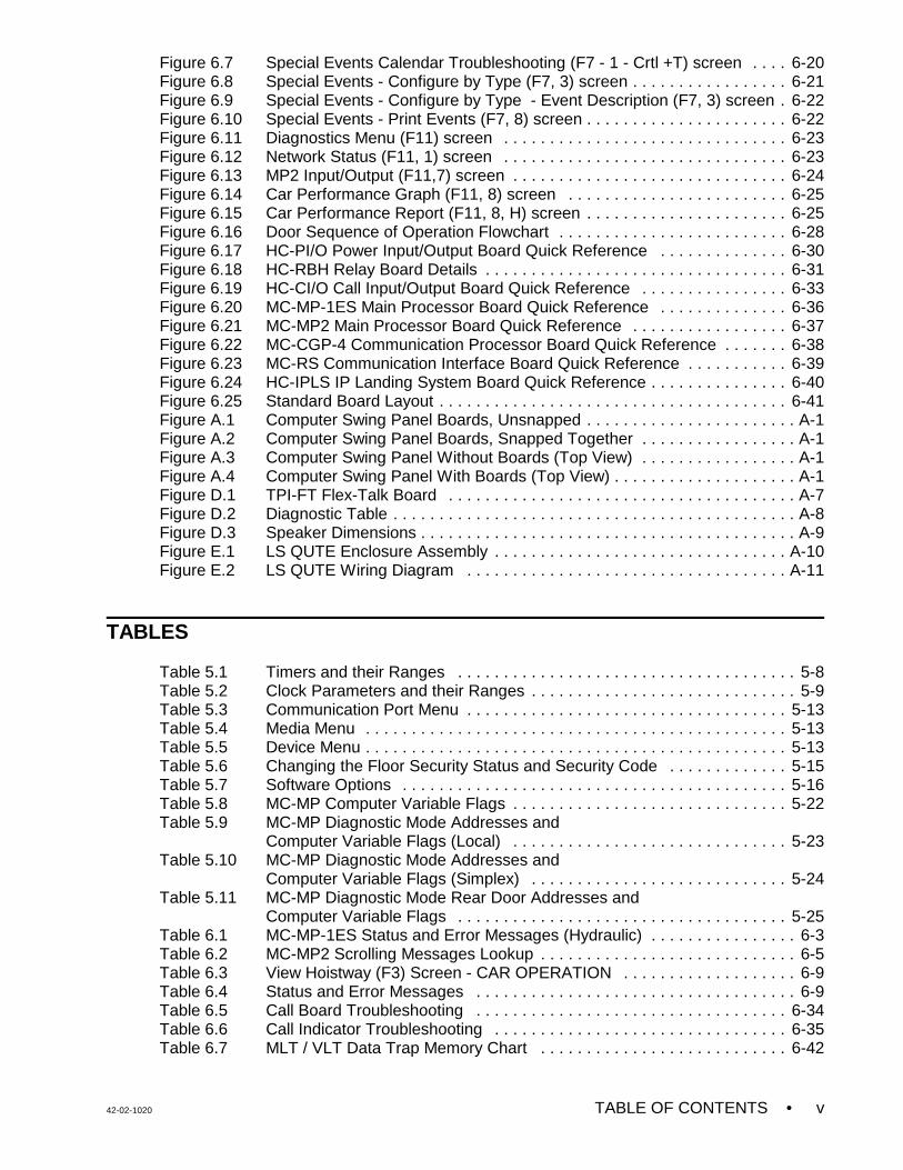
EQUIPMENT CATEGORIES - The HMC-1000 Controller consists of the following pieces ofequipment:
• Controller Unit• Car Top Selector (Landing system)• Peripherals• Group Dispatcher (2 or more cars only)
1.1 CAR CONTROLLER DESCRIPTION
Figure 1.1 shows a typical layout of the Car Controller in a standard MCE cabinet. A briefdescription of each block follows:
Î COMPUTER SWING PANEL - The Computer Swing Panel (Figure 1.2) houses thefollowing:
• MC-MP-1ES or MC-MP2 Main Processor Board• MC-CGP-4(8) Communication Processor Board (optional)• MC-RS Communication Interface Board (optional)
MC-MP-1ES or MC-MP2 Main Processor board - (see Figure 1.3) The Main Processor boardis located within the Computer Swing Panel and is responsible for Car Operation Control. Thisboard is also responsible for the On-Board Diagnostics that provide interactive communicationwith the elevator mechanic. The board contains the alphanumeric display and all the LEDs,switches, and buttons found on the front of the Computer Swing Panel.
FIGURE 1.1 Typical Physical Layout

42-02-1020 PRODUCT DESCRIPTION • 1-3
FIGURE 1.2 Computer Swing Panel
FIGURE 1.3 MC-MP2 Main Processor Board
• PRODUCT DESCRIPTION 42-02-10201-4
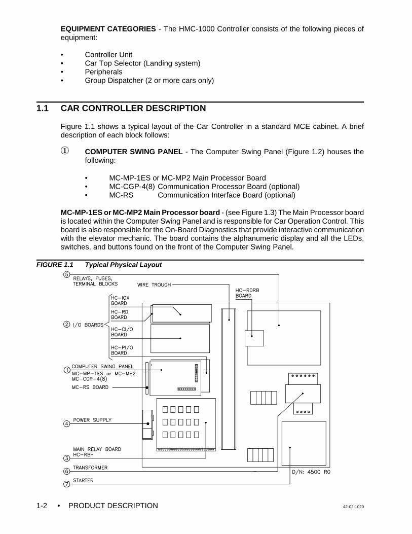
FIGURE 1.4 MC-CGP-4 Communication Processor Board
MC-CGP-4 Communication Processor Board - This board contains a very powerful 32-bitembedded RISC microcontroller, and is located along side the MC-MP-1ES or MC-MP2 MainProcessor Board. The primary function of this board is to co-ordinate the flow of informationbetween the car controller and other equipment and peripherals.
FIGURE 1.5 MC-RS Communication Interface Board
MC-RS Communication Interface Board - This board provides a high-speed RS-422 seriallink between the individual car controller and the M3 Group Supervisor. It also provides fourindustry standard RS-232C serial ports to interface the car controller with a standard computeror data terminal, such as a printer, modem or CRT terminal.
42-02-1020 PRODUCT DESCRIPTION • 1-5
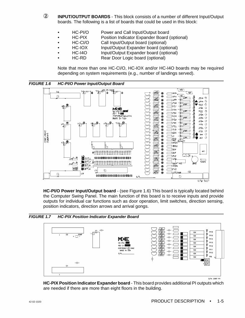
Ï INPUT/OUTPUT BOARDS - This block consists of a number of different Input/Outputboards. The following is a list of boards that could be used in this block:
• HC-PI/O Power and Call Input/Output board• HC-PIX Position Indicator Expander Board (optional)• HC-CI/O Call Input/Output board (optional)• HC-IOX Input/Output Expander board (optional)• HC-I4O Input/Output Expander board (optional)• HC-RD Rear Door Logic board (optional)
Note that more than one HC-CI/O, HC-IOX and/or HC-I4O boards may be requireddepending on system requirements (e.g., number of landings served).
FIGURE 1.6 HC-PI/O Power Input/Output Board
HC-PI/O Power Input/Output board - (see Figure 1.6) This board is typically located behindthe Computer Swing Panel. The main function of this board is to receive inputs and provideoutputs for individual car functions such as door operation, limit switches, direction sensing,position indicators, direction arrows and arrival gongs.
FIGURE 1.7 HC-PIX Position Indicator Expander Board
HC-PIX Position Indicator Expander board - This board provides additional PI outputs whichare needed if there are more than eight floors in the building.

• PRODUCT DESCRIPTION 42-02-10201-6
FIGURE 1.8 HC-CI/O Call Input/Output Board
HC-CI/O Call Input/Output board - This board processes hall call and car call inputs, callacknowledgment outputs, and displays the status of each call.
FIGURE 1.9 HC-IOX Input/Output Expander Board
HC-IOX / HC-I4O Input/Output Expander board - This is a multipurpose input/output board(Figure 1.9). Some installations have the HC-I4O board instead (Figure 1.10). Its functions aresimilar to the HC-IOX and HC-IOX-A.
FIGURE 1.10 HC-I4O Input/Output Expander Board

42-02-1020 PRODUCT DESCRIPTION • 1-7
HC-RD Rear Door board - This board provides the necessary logic required when anadditional independent rear door is present (board not pictured).
FIGURE 1.11 HC-RBH Relay Board Layout
Ð HC-RBH Main Relay Board - This board satisfies many of the code requirements forrelay contact redundancy and the requirements for normal terminal stopping devices.It also provides the necessary circuitry for running the car on Inspection or Accesswithout the benefit of computers. This board, along with the HC-PI/O board, comprisesthe high voltage interface between the MC-MP (MP2) computer and the individual carlogic functions such as door operation, direction outputs, direction sensing, main safetycircuits, leveling circuitry, etc.
There are typically 15 four-pole relays and terminals at the bottom of the board for fieldwiring. Test pads surround each relay for ease of troubleshooting. This board includesthe INSPECTION ON/OFF switch, the inspection car movement UP/DN switch and theTEST/NORM switch.

• PRODUCT DESCRIPTION 42-02-10201-8
Ñ POWER SUPPLY - The power supply (single output linear) provides +5VDC power tothe computer and its peripheral boards.
Ó RELAYS, FUSES AND TERMINAL BLOCKS - This block contains door operatorcircuitry, terminal blocks (for customer wiring), fuse holders, fuses, or any other circuitryneeded for a specific job.
Ô TRANSFORMERS - Transformers are provided, as necessary, according to therequirements of each individual car load and the available AC line voltage.
Õ STARTER - The starter is usually located in the lower right-hand corner of the controllercabinet along with the associated terminal blocks for motor connections. An across-the-line or Wye Delta starter is usually provided to operate the AC pump motor. ACoverloads are also provided
1.2 CAR CONTROLLER FUNCTIONAL LAYOUT
The Control Unit is divided into three primary sections. Figure 1.12 shows these functionalblocks and the printed circuit board types associated with each functional block:
• Car Operation Control (COC)• Car Communication Control (CCC)• Car Power Control (CPC)
1.2.1 CAR OPERATION CONTROL (COC)
Car Operation Control involves the logical car operation such as door operation, response tohall and car calls, and special operations such as Inspection/Access and Fire Service.Additional special operations are provided as required per specifications.
COC INPUTS - This section describes the main signals received by the MC-MP or MC-MP2Main Processor board.
The COC module is responsible for the “logical operation” of the elevator control system. Forexample, the COC may decide that the car should travel from one floor to another in responseto a car call. The fundamental inputs that are required for the logical control of the elevatorcome to the Main Processor board through two boards: the HC-PI/O board (power input/outputboard) and the HC-CI/O board (call input/output board). Each HMC-1000 control system hasone HC-PI/O board, and as many HC-CI/O boards as are required to accommodate thenumber of calls in the particular installation. Additional “miscellaneous” inputs come to the MainProcessor board through the HC-IOX and/or HC-I4O board (I/O expansion board, also as manyas needed).
Primary Power inputs - HC-PI/O board
C Door signals - The HC-PI/O board receives the door-related signals through the MainRelay board (HC-RBH). The door related signals include the door reopening devices(photo eye, safe edge), car operating panel buttons (door open button, door closebutton), and the door position contacts (door open limit, door lock).
C Landing system signals - The HC-PI/O board receives some of the signals generatedby the landing system through the Main Relay board (HC-RBH). The landing systemsignals read by the COC module are the door zone, level up and level down signals.

42-02-1020 PRODUCT DESCRIPTION • 1-9
C Operational mode signals - The HC-PI/O board receives a few of the operational andsafety mode signals through the Main Relay board (HC-RBH). These signals includethe safety string status, the inspection operation status, and the independent servicestatus. Additionally, some of the fire service signals are also received by the HC-PI/Oboard through the relay board (fire sensors, in-car fire service switch).
C Direction sensing inputs - Two direction sensing inputs (up sense and down sense)are read by the COC processor, again through the HC-PI/O and HC-RBH, and are usedto process the car position indicator logic and motor protection timing logic.
FIGURE 1.12 Car Controller Functional Layout
Call inputs (car call and hall call) - HC-CI/O board
The call buttons and call indicators are wired to the control system and read by the COCprocessor through the call board(s) (HC-CI/O). The connection to the HC-CI/O board is a singlewire connection for both the button and the indicator (the terminal acts as both an input andoutput terminal). In multi-car group arrangements, “system” hall calls are wired to the GroupSupervisor (also to HC-CI/O boards), but “swing car” hall calls are wired to the call board of theindividual car controller, along with the car calls.

• PRODUCT DESCRIPTION 42-02-10201-10
COC OUTPUTS - This section describes the main signals generated by the MC-MP or MC-MP2Main Processor board.
The fundamental outputs that are required for the logical control of the elevator emerge fromthe Main Processor board through the same two boards described above: the HC-PI/O board(power input/output board) and the HC-CI/O board (call input/output board). Additional“miscellaneous” outputs emerge from the Main Processor board through the HC-IOX or HC-I4OI/O Expansion boards, as many as are needed, and some “specialty” output boards which maybe used to drive specific devices.
Primary Power Outputs - HC-PI/O board
C Position indicators, direction arrows, and arrival fixture signals - Eight positionindicator outputs are provided on the HC-PI/O board. Should the particular installationhave more than eight landings, additional position indicator outputs are providedthrough the use of HC-PIX boards (position indicator expansion boards). The up anddown direction arrow indicators and the up and down arrival lantern outputs are alsoprovided on the HC-PI/O board. The output terminals for these indicator outputs arelocated on the HC-PI/O board.
C Fire service operation signals - Two outputs associated with fire service operation aregenerated on the HC-PI/O board, and are routed through the Main Relay board. Thefire warning indicator output generates the visual/audible signal in the elevator duringfire phase I recall, and the in-car stop switch bypass output is used for rendering the in-car stop switch inoperative, also during fire phase I recall.
C Door control signals - Four signals are generated by the COC module to control theoperation of the doors. These outputs are generated on the HC-PI/O board, but arerouted through the Main Relay board for connection to external relays. These signalsare the door open function, door close function, door close power, and nudging outputs.Should the installation have a floor with both front and rear openings, a rear door logicboard (HC-RD) is used to generate the corresponding outputs for the rear door.
C Car movement signals - Four signals are generated by the COC module to performthe logical control of car movement. In hydraulic applications these signals directlycontrol the valve solenoids to cause the car to move up and down at high and lowspeeds.
Call outputs (car call and hall call) - HC-CI/O board
The call button indicators are wired to the control system and generated by the COC modulethrough the HC-CI/O call board(s) The connection to the HC-CI/O call board is a single wireconnection for both the indicator and the call button (the terminal acts as both an input andoutput terminal). In multi-car group arrangements, “system” hall calls are wired to the GroupSupervisor, but “swing car” hall calls are wired to the call board of the individual car controller,along with the car calls.
1.2.2 CAR COMMUNICATIONS CONTROL (CCC)
This functional block coordinates the flow of information between the car controller and otherequipment such as terminals, modems, printers and the Group Supervisor in an M3 GroupSystem.

42-02-1020 PRODUCT DESCRIPTION • 1-11
FIGURE 1.14 LS-QUTE Car Top Control BoxFIGURE 1.13 LS-STAN Car Top Control Box
1.2.3 CAR POWER CONTROL (CPC)
This functional block is comprised of the relay circuits which control direction, safety, access,inspection and pump motor control.
1.3 LANDING SYSTEM CONTROL BOX
The Landing System is designed to be mounted on the car top. There are two types of landingsystems that can be used with HMC-1000 controllers: LS-STAN and LS-QUTE.
LS-STAN - The LS-STAN is the standard landing system. The car top control box uses VS-1Ainfrared proximity switches to sense vanes that are mounted in the hoistway.
LS-QUTE - The LS-QUTE is a tape-and-magnet-operated landing system, with a three inchwide steel tape mounted in the hoistway. The car top control box has a floating head that slideson the steel tape, and magnetic sensors for slow down, STU, STD, ISTU, ISTD, LU, LD andDZ. Optional absolute floor encoding is available. Refer to Appendix H, LS-QUTE LandingSystem Assembly Drawings, for more information.

• PRODUCT DESCRIPTION 42-02-10201-12
1.4 DIAGNOSTIC TOOLS AND PERIPHERALS
Refer to Section 5, Human Interface, for more information about the diagnostic tools availableusing the controller's Computer Swing Panel. Refer to the Computer Peripherals Manual, MCEpart number 42-02-CP00, for more information about the diagnostic tools available using a CRTor PC.
1.5 GROUP SUPERVISOR (2 OR MORE CARS)
If this controller is part of an M3 Group System, refer to the M3 Group Supervisor Manual, MCEpart number 42-02-G004, for more information about group operation.

42-02-1020 INSTALLATION • 2-1
SECTION 2INSTALLATION
2.0 GENERAL INFORMATION
This section contains important recommendations and instructions for site selection,environmental considerations, installation guidelines and other factors that will help ensure asuccessful installation.
2.0.1 SITE SELECTION
In choosing a proper location for the control equipment, the following factors should beconsidered:
• Provide adequate working space for comfort and efficiency.
• Mount the controller in a logical location, taking into consideration the location of otherequipment in the machine room and proper routing of electrical power and controlwiring. Note that MCE controllers do not require rear access.
• Do not install equipment in a hazardous location.
• Provide adequate space for future expansion, if possible.
• If any areas in the machine room are subject to vibration, they should be avoided orreinforced to prevent equipment from being adversely affected.
• Provide adequate lighting for the control cabinets and machines in the machine room.A good working space such as a workbench or table is recommended.
2.0.2 ENVIRONMENTAL CONSIDERATIONS
The following are some important environmental considerations which will help to increase thelongevity of the elevator equipment and reduce maintenance requirements:
• Provide an ambient temperature that will not exceed 32E to 104E F (0E to 40E C).Operation at higher temperatures is possible, but not recommended, because it willshorten the life of the equipment. Adequate ventilation and possibly air conditioning maybe required.
• The air in the machine room should be free of excessive dust, corrosive elements orexcessive moisture to avoid condensation. A NEMA 4 or NEMA 12 enclosure wouldhelp meet these requirements. If open windows exist in the machine room, locate thecontroller away from the windows so that severe weather does not damage theequipment.
• High levels of radio frequency (RF) radiation from nearby sources may causeinterference to the computers and other parts of the control system. Using hand-heldcommunication devices in close proximity to the computers may also causeinterference.
• Power line fluctuation should not be greater than +/-10%.

• INSTALLATION 42-02-10202-2
NOTE: DRAWING NAME - Some drawings have a drawing name directly abovethe title block or at the top of the drawing. The drawing name may be usedto refer to a particular drawing.
2.0.3 RECOMMENDED TOOLS AND TEST EQUIPMENT
For proper installation, use the following tools and test equipment:
• A digital multimeter, Fluke series 75, 76, 77 or equivalent• A hand-held tachometer• A clamp-on AC ammeter• Hand-held radios• A telephone• Test weights• Pressure gauge• Soldering tools, a flashlight and an MCE screwdriver (provided with controller).
2.0.4 THE WIRING PRINTS
Become familiar with the following information as well as the wiring prints provided with thiscontrol system.
DRAWING NUMBER FORMAT - Each print has a drawing number indicated in the title block.The drawing number is comprised of the job number, car number and page number (seeexample). In this manual the drawings will often be referred to by the last digit of the drawingnumber (page number). The following is the drawing number format currently in use.
NOMENCLATURE - The following is an example of the schematic symbols use to indicate thata signal either enters or exits a PC board.
A listing of PC boards and their designator numbers plus other schematic symbols used in thewiring prints can be found at the beginning of the Job Prints and in Appendix C of this manual.

42-02-1020 INSTALLATION • 2-3
CAUTION: Do not allow any metal chips or drill shavings to fall into theelectronics.
• Become familiar with the "Elevator Car Wiring Print" drawing number -1.
• Become familiar with the "Elevator Hoistway Wiring Print" drawing number -2.
• Group interconnects to individual car cabinets (two or more cars) are shown on thedrawing titled “Group Interconnects to Individual Car Cabinets.”
• The power connections and power supplies are shown in drawing number -3.
• Review any additional wiring diagrams and details.
• The remainder of the job prints are detailed drawings of the HMC-1000-HC hydrauliccontrol system.
• A specific part of a schematic may be referenced by the Area Number, which is foundat the left-hand margin of the schematic.
2.1 CONTROLLER INSTALLATION
Mount the controller securely to the machine room wall or other appropriate location and cutholes to install a raceway or conduit to permit the routing of wires into the cabinet. Note that thestandard MCE control cabinet does not require rear access.
2.1.1 CONTROLLER WIRING GUIDELINES
a. PC boards can be easily damaged by Electrostatic Discharge (ESD). Use a properlygrounded wrist strap when touching the PC boards.
Do not touch PC Boards unless you are properly grounded.
b. Bring wires in from a location that allows the use of the wiring duct inside the controllerto route the wires. The terminals are found conveniently near wiring ducts.
c. When routing field and/or power wiring, avoid the left side of the HC-PI/O and HC-CI/Oboards.

• INSTALLATION 42-02-10202-4
WARNING: Connecting the Group Supervisor directly to the building AC supplymay cause damage to PC boards. Also, connecting out-of-phasepower will cause damage. Check the “phasing” of the individual car2-bus lines before connecting them to the Group Supervisor. With avoltmeter set to AC Volts, measure between adjacent car 2-busterminals. The meter must read less than 10 VAC. If the reading ishigher, reverse the power leads going to the car's T1 transformer atL1 and L2, and measure again.
d. Connect the wires to the controller according to the hoistway and car wiring diagrams.
e. If the car is part of a group system, there are a number of details relating to the wiringof the interconnects between the individual cars. They are as follows:
1. If a group controller cabinet is provided, refer to the drawing titled “GroupSupervisor Field Wiring Print” in the job prints. Power for the M3 GroupSupervisor cabinet comes from the local Car Controllers as shown in drawing(-2). The main AC power supply wiring size must be determined by the electricalcontractor.
2. A separate conduit or wiring trough must be provided for the high speed seriallink from each car controller to the Group Supervisor cabinet. The wiring for thehigh speed communication link is fully detailed in the print titled "Instructions forConnection of High Speed Communication Cables." The wiring details shouldbe followed exactly. Again, note the requirement for routing the high speedinterconnect cables through a separate conduit or wiring trough.
3. If applicable, also wire according to the print titled "Group Interconnects toIndividual Car Cabinets." Be sure to ground all cabinets according to Section2.2.1.
4. The field wiring to the Group Supervisor cabinet is found in the print titled“Group Supervisor Field Wiring Print”.
2.2 GENERAL WIRING GUIDELINES
Basic wiring practices and grounding requirements are discussed in this section.
2.2.1 GROUND WIRING
To obtain proper grounding, quality wiring materials and methods should be used.
All grounding in the elevator system must conform to all applicable codes. Proper groundingis essential for system safety and helps to reduce noise-induced problems. The following aresome grounding guidelines:
• The grounding wire to the equipment cabinet should be as large as, or larger than, theprimary AC power feeders for the controller and should be as short as possible.
• The grounding between equipment cabinets may be branching or a daisy chain, but thewire must terminate at the last controller and NOT loop back (see Figure 2.1).
42-02-1020 INSTALLATION • 2-5
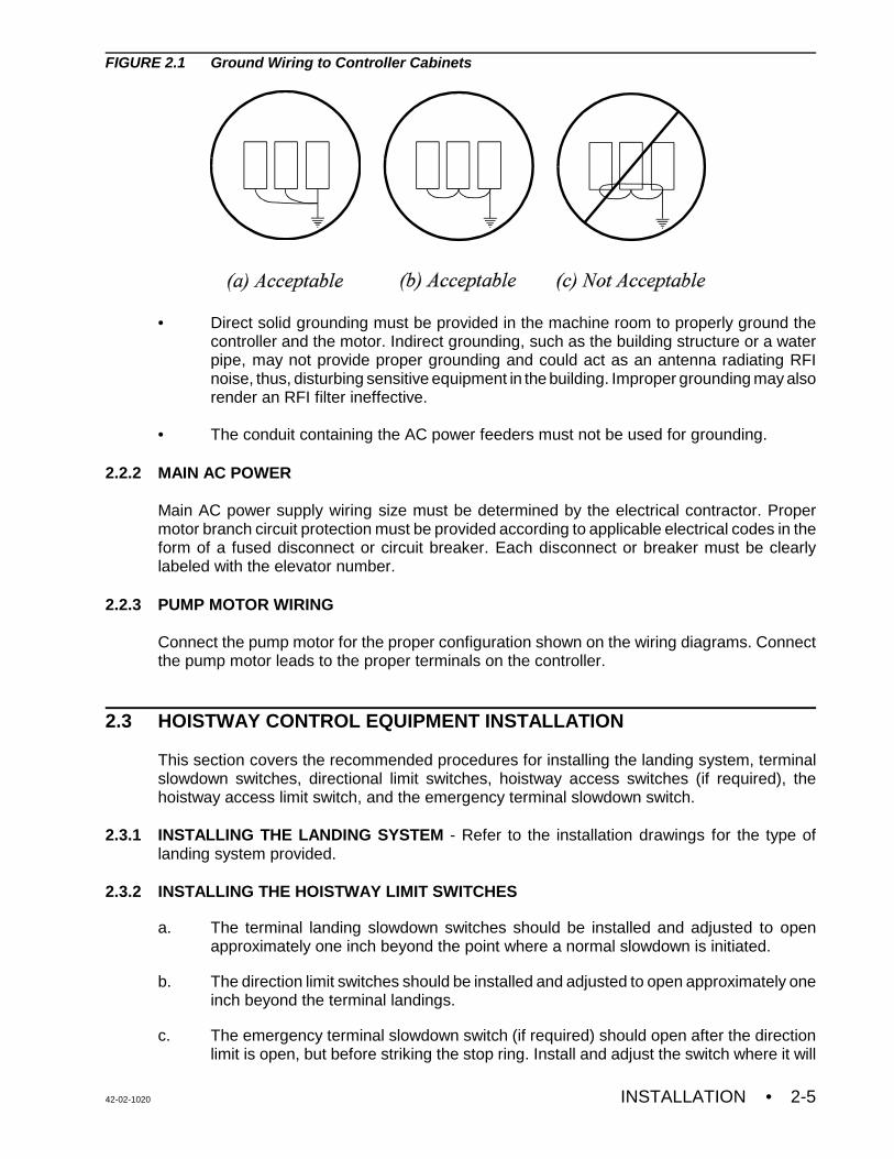
FIGURE 2.1 Ground Wiring to Controller Cabinets
• Direct solid grounding must be provided in the machine room to properly ground thecontroller and the motor. Indirect grounding, such as the building structure or a waterpipe, may not provide proper grounding and could act as an antenna radiating RFInoise, thus, disturbing sensitive equipment in the building. Improper grounding may alsorender an RFI filter ineffective.
• The conduit containing the AC power feeders must not be used for grounding.
2.2.2 MAIN AC POWER
Main AC power supply wiring size must be determined by the electrical contractor. Propermotor branch circuit protection must be provided according to applicable electrical codes in theform of a fused disconnect or circuit breaker. Each disconnect or breaker must be clearlylabeled with the elevator number.
2.2.3 PUMP MOTOR WIRING
Connect the pump motor for the proper configuration shown on the wiring diagrams. Connectthe pump motor leads to the proper terminals on the controller.
2.3 HOISTWAY CONTROL EQUIPMENT INSTALLATION
This section covers the recommended procedures for installing the landing system, terminalslowdown switches, directional limit switches, hoistway access switches (if required), thehoistway access limit switch, and the emergency terminal slowdown switch.
2.3.1 INSTALLING THE LANDING SYSTEM - Refer to the installation drawings for the type oflanding system provided.
2.3.2 INSTALLING THE HOISTWAY LIMIT SWITCHES
a. The terminal landing slowdown switches should be installed and adjusted to openapproximately one inch beyond the point where a normal slowdown is initiated.
b. The direction limit switches should be installed and adjusted to open approximately oneinch beyond the terminal landings.
c. The emergency terminal slowdown switch (if required) should open after the directionlimit is open, but before striking the stop ring. Install and adjust the switch where it will

• INSTALLATION 42-02-10202-6
not interfere with Inspection or Automatic operation while leveling or releveling. It mustalso be adjusted to achieve the required operation according to the applicable elevatorcode.
d. Ensure that the cam that operates the slowdown and limit switches maintains theterminal slowdown switch open until the direction limit switch and emergency terminalslowdown switches (if required) are open.
e. Ensure that the terminal slowdown, direction limit and emergency terminal slowdownswitches are held open for the entire runby or overtravel of the elevator.
f. The hoistway access limit switch (if required) should be installed and adjusted to openand stop the elevator (in the down direction), when the top of the elevator isapproximately level with the top landing (when the top hoistway access switch isactivated while on Access or Inspection operation).
2.3.3 INSTALLING THE LANDING SYSTEM CONTROL BOX (LS-QUTE) - Refer to the drawingsin the job prints.
• The location for the landing system box should have already been selected.
• Holes are available on both sides and on the bottom of the landing system box formounting to any support brackets or structural channels. The mounting of the boxshould be very firm and solid so that knocking it out of alignment should be difficult. Use1/4-20 hardware.
• To install the tape into the tape guides on the LS-QUTE landing system box, removethe 2 thumbscrews on the 2 guide assemblies, insert the tape and reinstall the guideswith the thumbscrews (tighten firmly). If the installation has the LS-QUTE car topselector with the additional sensor bracket on the rear of the tape, first remove the three8-32 screws holding the protective 1" wide channel. This channel covers the back of theDoor Zone sensors on the upper tape guide bracket. Remove the single standoff thatis in the way of the thumbscrew holding the tape guide. Remove the thumbscrewsholding the upper and lower tape guides, insert the tape, and reinstall the guides withthe thumbscrews (tighten firmly). Reinstall the standoff (do not over-tighten) and theprotective channel.
• After inserting the steel tape into the tape guides, check the location of the landingsystem box. The car should be at the top of the hoistway to make it easier to see if thealignment is causing any stress or binding on the tape guides. Make sure that the boxis vertical and plumb with the tape. This allows for easy tape movement and avoidsexcessive wear on the tape guides (using a level is helpful). Be careful so as to avoidpremature failure of the tape guides.
• Move the elevator to the top and bottom of the hoistway to check for smooth tapemovement and to make sure that there is no excessive pressure on the tape guides.Correct any problems immediately.
2.3.4 INSTALLING THE MAGNETIC STRIPS ON THE STEEL TAPE
a. Carefully, read and follow the Magnet Installation instructions in the job prints, but readthe rest of these instructions before proceeding.

42-02-1020 INSTALLATION • 2-7
b. Before installing the magnets, clean the steel tape thoroughly with an appropriatesolvent. No oil should be left on the tape as it will interfere with the adhesive backingon the magnets.
c. There are normally five lanes of magnets installed on the side of the tape facing the car.One lane consists of only the LU/DZ/LD and requires that a 6-inch magnet be installedat each floor. The other lanes have magnets which initiate slow downs.
d. If the installation has rear doors, it may have an LS-QUTE landing system which hasadditional Door Zone sensors on the rear of the upper tape guide assembly. Follow theMagnet Installation instructions in the job prints and install the front and rear Door Zonemagnets on the steel tape as shown.
2.3.5 DOOR POSITION MONITOR SWITCH (IF USED)
If you are in a jurisdiction where ASME A17.1 - 1996 or later is being enforced, Door PositionMonitor switch(s) connected to the DPM and/or DPMR inputs, must be added to monitor theposition of the closed doors. This must be a separate physical limit switch that makes upapproximately 1 to 2 inches before the doors lock.

42-02-1020 START-UP • 3-1
NOTE: A short to ground is defined as a resistance of less than 20 ohms betweenthe 1-bus (common) and the terminal being checked.
NOTE: These instructions also assume adequate electrical troubleshootingexperience. Follow the procedure carefully. If the elevator does not respondcorrectly, check the circuits according to your ability. Proceed cautiously.Read these instructions all the way through to become familiar with theprocedure before starting the work.
SECTION 3START-UP
3.0 GENERAL INFORMATION
This section discusses preparing the car to run on Inspection operation and covers thesequence of applying power to the controller and its associated components and verifyingproper phase sequence and motor rotation. It also covers completing the initial adjustment ofthe system to get basic car movement on Inspection operation.
3.1 GROUND CHECK
Perform a ground test before powering up the system. Set the multimeter on the RX1 range(100 to 200 ohm range). Take all measurements with respect to the 1-bus, which is alsoreferred to as the system common elsewhere in this manual. .
a. Remove fuse F4. If this a fire recall system, consult the schematics and remove thefuse that powers terminal 2F. Check for shorts to ground on the terminal 2F.
b. Check for shorts to ground on all terminals on the bottom of the HC-RBH Main Relayboard. Terminal 89 is the only terminal that should be grounded.
c. Check for shorts to ground on all terminals on the HC-PI/O (and HC-CI/O-E boards, ifpresent).
d. Check for shorts to ground on door operator terminals. Consult the job prints todetermine which fuses to remove and check the appropriate terminals for shorts toground.
3.2 BEFORE APPLYING POWER
a. Unplug the screw terminal blocks from the HC-PI/O and any HC-IOX or HC-CI/O-Eboards by moving the blocks toward the right. This is done to avoid damaging theboards by accidentally shorting one of the output devices to one of the power buses(terminals 2, 3, or 4) during the initial power-up of the system.

• START-UP 42-02-10203-2
NOTE: The HMC-1000 Controller is equipped with an INSP. SPEED HI-LO switchto allow the car to be run at either high or low speed on car top Inspectionor hoistway Access operation. For these operations the car should NOT berun at high speed if the contract speed is greater than 150 fpm.
b. With all power OFF, remove one side of the ribbon cable connecting the MainProcessor board to the HC-PI/O board at connector C3, by pushing the two latches onC3 open and removing the ribbon cable.
c. In the following instructions, it is assumed that all hoistway doors are closed, but notnecessarily locked, and all hoistway and machine room wiring is complete. Thehoistway limit switches must be adjusted to the manufacturer’s specifications. Correctany malfunction before continuing further.
3.3 APPLYING POWER
3.3.1 INITIAL ADJUSTMENTS AND POWER PHASING
a. Install a jumper wire between terminal 4 and 8 on the HC-RBH board to override thegate switch and the door locks.
b. Ensure that the Soft Stop jumper (below the AA relay) is in the OFF position by carefullypulling it straight out from the board and plugging it back in correctly. It may be tight, sobe careful.
c. If a field wire is connected to terminal 59 on the HC-RBH board, temporarily remove thewire, label and and insulate it. This will disable the Car Top Inspection switch.
d. Turn ON power to the controller by closing the machine room disconnect switch.
e. Check pump motor rotation by briefly pushing in the starter (or WYE switch, if there isWYE-DELTA starting). If the rotation is not correct, reverse any two of the three leadsat the main disconnect switch. If an RP (Reverse Phase) sensor is provided and thesensor contact does not close when power is applied to the controller (indicated by alight on the sensor that comes on when phase rotation is correct), then 2 of the 3 ACwires that connect to the RP sensor may have to be reversed. Some contactors maynot make up when activated by hand. Use a push-button relay for AA on the HC-RBHboard to check the motor rotation.
f. On the HC-RBH Main Relay board, place the INSP. SPEED HI-LO switch in the LOposition and adjust the valves for proper low speed operation.
42-02-1020 START-UP • 3-3
NOTE: MCE's HMC-1000 HC controller is designed to operate on Inspection andAccess without the computers hooked up during start-up.
3.3.2 MOVING THE ELEVATOR ON INSPECTION
a. Turn OFF power at the main disconnect and reinstall fuses F4, F7 and F8 (and anyother fuses that may have been removed during the ground check).
b. Place the Relay Panel Inspection ON/OFF switch in the ON position (this switch isfound on the left-hand side of the HC-RBH Relay board).
c. Install a temporary jumper between terminals 18 and 59 on the HC-RBH board. Turnthe power ON and verify that the RPI relay is picked, thereby placing the car onInspection operation. If the RPI relay is not picked check the connections in the SafetyString.
d. Move the car up and down with the Relay Panel Inspection UP/DN switch. The followingrelays must pick in the up direction: AA, RPI, SAF, Y, BB and DELTA. If AA and BB arenot picked, check to see that relays IN1 and IN2 have dropped out (de-energized). Ifno relays are picked, check the F4 fuse and check to see that there is 120VAC betweenterminals 1 and 2. If SAF is picked and AA is not, check the starter overload contacts.If SAF is not picked, briefly jumper 2 to 20 (bypass the Safety String). If SAF pickswith the jumper in place, the trouble is in the safety string. If SAF still does not pick,check the RP sensor again.
e. Adjust the BB timer potentiometer on the HC-RBH board to transfer from WYE toDELTA just as the pump motor reaches maximum rpm from a dead stop.
f. Adjust the valves for proper Inspection operation.
3.3.3 PREPARING THE CAR TO RUN ON AUTOMATIC OPERATION
a. Turn OFF the power at the main disconnect.
b. Complete and finalize installation and all wiring. Hook up the field wires for the car calls,hall calls and PIs into their respective terminals (remember that the plug-in terminalshave yet to be inserted into the boards). Connect one probe of the meter to the 1-busand with the other probe, check all of the call and PI terminals for shorts to ground.Connect the common probe of the meter to the 2, 3 and 4 buses sequentially whilechecking for shorts to the call, PI, direction arrow and terminals 40 183 and 184.
c. Turn ON power at the main disconnect and probe the call and PI terminals again. Thistime, check to make sure that there is no voltage present on any of the PI terminals withrespect to the 1-bus. Jumper each of the call terminals one-by-one to ground orterminal 1. Verify that no fuses blow, especially F4. Turn OFF the power at the maindisconnect.
d. Plug the call and PI terminal blocks back into the appropriate boards.
e. Remove the jumper from terminal 18 to 59 and put the field wire back into terminal 59on the HC-RBH board. With the power ON, verify that no AC voltage exists on terminal59 with respect to the 1-bus. Note that Car Top Inspection prevents Relay PanelInspection operation.

• START-UP 42-02-10203-4
3.4 PREPARATION FOR FINAL ADJUSTMENT
a. Verify that the door operator is operating properly with all door equipment (clutches,rollers, etc.) properly adjusted with the correct running clearances.
b. Verify that the car doors are closed and that all hoistway doors have been closed andlocked. Run the car on Inspection through the hoistway to make sure that the hoistwayis completely clear. Check to see that the landing system has been installed accordingto the installation instructions. Place the car at the bottom of the hoistway.
c. Place the TEST/NORM switch on the HC-RBH Relay board in the TEST position.

42-02-1020 FINAL ADJUSTMENT • 4-1
NOTE: Pin 1 on both the ribbon cable connector and the header on the HC-PI/Oboard must match. These are designated with arrows on the connectorand header. Press the connector in until the latches snap, securing theconnector in place.
NOTE: If the car is not completely wired (temporary), check the following:• wire removed from panel mount terminal DCL• wire removed from terminal 47 on the HC-RBH board• jumper from 2 bus to terminal 36 on the HC-RBH board• jumper from 2 bus to terminal 38 on the HC-RBH board• jumper from 2 bus to panel mount terminal EPI (if present)
SECTION 4FINAL ADJUSTMENT
4.0 GENERAL INFORMATION
At this point all of the steps in Section 3 should have been completed. Please read Section 5before proceeding: it explains the adjustment and troubleshooting tools available with thecomputer. This section contains important recommendations and instructions for operating theelevator on Automatic operation.
4.1 RUNNING ON AUTOMATIC OPERATION
Move the car to the bottom landing on Inspection operation and turn the power OFF. Reinsertconnector C2 into receptacle C2 on the HC-PI/O board (if previously removed).
a. If the door operator is not working, pull the door fuses and close the doors so that thedoor clutch will not hit any of the door lock rollers. Take whatever steps are necessaryto keep the installation safe, but make sure that the car top is still accessible afterclosing all of the doors. Turn ON the AC power to the elevator.
b. Temporarily take the car off of Inspection operation. If the Diagnostic Indicators do notshow Test Mode, see what message is being displayed and correct the problem. Forexample, if the indicators show that the car is on Fire Service Phase 1, a jumper mustbe connected between terminal 2 on the back plate and terminal 38 on the HC-RBHboard in order to run the car on Normal operation. Remove the jumper once the FireService input is brought into the controller. Place the car on Inspection.
4.1.1 STATUS AND DIAGNOSTIC INDICATORS
Section 5 of this manual describes the onboard diagnostic tools that are available through theComputer Swing Panel. These diagnostic tools simplify the adjustment and troubleshooting ofthe system. It is important that Section 5 be read and understood before proceeding.
When the Diagnostics On/Norm switch is in the Norm position, the Diagnostic Indicatorsindicate when the system is ready for Normal operation. The Diagnostic Indicators must bescanning from right to left one light at a time. If the Diagnostic Indicators are flashing any other

• FINAL ADJUSTMENT 42-02-10204-2
way, an abnormal or special condition exists. Table 5.1 (MC-MP Status and Error Messages)provides a list of abnormal or special conditions. Note that some conditions take priority overothers. For example, if the safety string is open and the system is in Fire Service mode, thecomputer will show that the safety string is open and will expect the mechanic to correct thisproblem first since it is a higher priority condition.
Once the safety string has been made up and the computer recognizes this, then the computerwill show that the car is on Fire Service mode. After successfully bringing in the Fire Serviceinput, the computer will then start its normal scan. Once scanning normally, it is then possibleto place calls and run the elevator automatically.
The controller has indicators for car position and direction. All calls are also displayed on thecontroller. A special feature is provided on the HC-CI/O Call Input/Output boards to show whenan incandescent call light bulb is burned out. If a call bulb is burned out, the associated callLED on the HC-CI/O board will be lit dimly when a call is not registered and will be lit normallywhen a call is registered. If this job has non-incandescent indicators for calls, such as neon,check with MCE to make sure the Call boards are arranged appropriately, otherwise the burnedbulb feature will not work.
4.1.2 ABSOLUTE FLOOR ENCODING
Absolute floor encoding is an option which allows the controller to read encoding vanes ormagnets at each landing and thereby identify the floor. If the absolute floor encoding optionis provided, the behavior of the car, when power is turned ON, is different from the behavior ofa car without absolute floor encoding.
JOBS WITHOUT ABSOLUTE FLOOR ENCODING - If the car is in the middle of the hoistwaywhen power is turned ON, the controller will not know where the car is and must send the carto the bottom landing to get in step with the floor Position Indicator. It does so by generatingan internal BFD (Bottom Floor Demand) flag in the computer. When the BFD flag is present,no car calls will be accepted until the car reaches the bottom terminal. The BFD flag will becleared when the DSD (Down Slow Down) cam-operated switch has opened (dropping powerto terminal 13) if DZ (Door Zone) and DLK (Door Locked) are both active. If the car is onAutomatic Operation, and if a home floor has been designated, the car will move to the homelanding at this time.
If the car is put on Relay Panel Inspection or Car Top Inspection operation and then is returnedto Automatic operation, if the car is not at a terminal landing, the controller will create the BFDflag and will act as described above. If the BFD flag is present, and the TEST/NORMAL switchis on TEST, it will be necessary to place a jumper between terminals 2 and 45 (Door Closeinput) to move the car. It may be necessary to hold the jumper on the terminals for severalseconds.
JOBS WITH ABSOLUTE FLOOR ENCODING - If the car is not at a landing when power isturned ON, the controller will generate a down direction command and the car will move towardthe closest landing, provided that all abnormal conditions have been corrected. When the carreaches a landing and is within the Door Zone (relay DZ picked) with leveling completed (relaysLU and LD not picked) the controller reads the floor code vanes or magnets and corrects thePosition Indicator. If the car is on Automatic Operation, and if a home floor has beendesignated, the car will move to the home landing at this time. If the car is at a landing, withinthe Door Zone (relay DZ picked) with leveling completed (relays LU and LD not picked) whenAC power is turned ON, the controller will read the floor code vanes or magnets at the landingand correct the Position Indicator. Again, if a home floor has been designated, the car will moveto this landing to park.

42-02-1020 FINAL ADJUSTMENT • 4-3
CAUTION: The call terminals on the HC-PI/O and HC-CI/O-E board should neverbe connected to any of the power terminals (such as 2, 3, 4, etc.). Ifthis happens and the call is turned on, it will blow the resistor-fuse ortriac which plugs into the Call board. Later versions of these boardsmay have plug-in zener diodes. These parts are designed to be fieldreplaceable and spares are provided in unused positions on the Callboard, or are available from MCE. DO NOT JUMPER THESE PLUG-IN COMPONENTS AS IT MAY DESTROY THE BOARD OR OTHERCONTROLLER COMPONENTS. If any of these components shouldblow, FIND OUT WHY instead of constantly replacing them, as theconstant faults can eventually damage the board.
4.1.3 REGISTERING CAR CALLS
In the process of making final adjustments to the controller, periodically you will be asked toregister car calls. A call or series of calls can be registered at the controller by momentarilyplacing a jumper between terminal 1 (system common) and the desired car call terminal orterminals on the HC-PI/O or HC-CI/O-E board, and then between terminal 2 and terminal 45to allow the car to travel to each call. The car may move immediately after the first call is putin, or it may wait several seconds before moving.
4.1.4 TEST MODE OPERATION
The purpose of Test mode is to allow easy and convenient operation of the car so that the finaladjustments can be made without cycling the doors. When the elevator is operated in the TESTmode, the elevator doors do not open. The door open relays are disconnected automaticallyduring Test mode operation.
Put the car into TEST mode by placing the TEST/NORMAL switch on the HC-RBH (Main Relayboard) in the TEST position. Note that when the TEST/NORMAL switch is in the TESTposition, it puts the car on Independent Service, provided that the Car Top Inspection andRelay Panel Inspection switches are in the OFF or normal positions. In that case, the StatusIndicators should show Independent Serv. If the expected indication is not displayed, checkto see what message is being displayed and correct the problem.
During the final adjustments, calls will be placed at various floors with the TEST/NORM switchon TEST. To get the car to move, a jumper must be connected between terminal 1 (or ground)and the desired car call terminal, until the car actually starts. If a CRT is available, calls canbe entered using the CRT terminal's F3 screen.
Operation while in Test mode should be easy to understand by knowing the following:
a. Every time the car stops, a non-interference timer must elapse before the car can moveagain (the car will not move unless there is another car call). Note that after the timerhas elapsed, the car will move immediately as soon as the next car call is placed (thecar will not move if the system is a single button collective system and there is nojumper from terminal 2 to terminal 45). Placing a car call right after the car stops willrequire the non-interference timer to elapse before the car can move again.
b. Simply having one or more car calls registered will not necessarily cause the car tomove. It will be necessary to jumper terminal 2 to terminal 45 to create a Door CloseButton input to get the car to move. If the car is not a single button collective but is aselective-collective, the jumper from terminal 2 to 45 will not be necessary. Leave a

• FINAL ADJUSTMENT 42-02-10204-4
jumper connected from terminal 1 to the last car call in the line of calls that have beenplaced. This will create a constant pressure signal on the car call which is an alternatemeans of creating a Door Close Button signal to get a car that is on IndependentService to leave the landing. However, the jumper from terminal 2 to terminal 45 maybe more convenient.
c. If a jumper from terminal 1 is touched to the car call input for the floor where the car islocated, it will reestablish the non-interference timer and it must elapse before the carcan move again.
d. If the elevator is trying to level, it will not pick high speed and leave the landing until ithas completed the leveling process. Drive Unit speed adjustments and direction limitsat terminal landings may cause this problem.
e. If any of the inputs that open the door are active (Safety Edge On, Photo Eye On, CarCall input grounded to 1 for the floor matching the Position Indicator, etc.) the car willnot leave the landing.
f. Both slowdown switch inputs (terminals 11 and 13) should never be opensimultaneously. One or both should have power if the safety circuit is complete and thedoors are closed and locked.
4.1.5 SWITCHING TO AUTOMATIC OPERATION
a. Place the car on Inspection operation.
b. Move the car to the bottom terminal landing. Check to see if the DZ relay is picked. Ifnot, move the car on Inspection to place it in the Door Zone.
c. Place the Relay Panel Inspection switch in the OFF position. If the car is not at alanding, it will move to a landing. If the car is at a landing but not in the door zone, eitherthe LU or LD relay should pick and the car should perform a relevel. If the relevel in notsuccessful, check the following:
C If the LD relay is picked, but the brake and other relays are not, the downdirection limit switch may be preventing the leveling down operation.
C If the car is trying to level, it will not leave the landing for a call until the levelingis complete. Move the limit switch if necessary.
The Status Indicator lights should now display the indication for Independent Service operation.At this time the Position Indicator should match the actual car location. Note that all of thePosition Indicators and direction arrows are conveniently displayed on the controller. All thecalls are also displayed on the controller.
4.2 FINAL ADJUSTMENTS
4.2.1 DOOR OPERATOR ADJUSTMENTS
Install the fuses for the door operator(s) and complete the final adjustments. Doors can beopened at 3" before the floor or at the floor (non-pre-opening option). Hydraulic elevators areusually set up to open the doors only after the car stops, but pre-opening is available. ContactMCE Customer Service.
42-02-1020 FINAL ADJUSTMENT • 4-5
4.2.2 HYDRAULIC VALVES
Adjust hydraulic valves for proper speed, acceleration, deceleration, etc. and check contractspeed. A hardware timer on the HC-RBH board automatically provides pump motor overrunfor Soft Stop operation. Ensure that the Soft Stop jumper is in the ON position for it to be onand in the OFF position for it to be off.
4.2.3 SLOWDOWN AND LIMIT SWITCHES
Disconnect the stepping switch inputs for 3 or more landings and verify proper operation of allslowdown and limit switches for slowing and stopping the car at both terminal landings.
4.2.4 HALL CALLS
Place hall calls for all of the landings and make sure all hall calls function properly.
4.2.5 OPTIONS
Verify the operation of the following options: Independent Service, Fire Return Phase 1 (MainFloor and Alternate Floor operation, if provided), Fire Phase II In-Car operation, and any otheroptions provided.
4.2.6 DOOR OPEN/CLOSE PROTECTION
The elevator controller is provided with door open protection and door close protection. If thedoors do not open after several seconds, the car will give up and continue to the next call. Afterthe car starts to close the doors and the doors do not lock, it will recycle the doors open andattempt to close the doors three times before a DLK fail error.
4.2.7 MOTOR LIMIT TIMER
A motor limit timer is provided to take the car to the bottom landing and open the doors if themotor is operating for too long.
4.2.8 VALVE LIMIT TIMER
The same is true for the valves with the down valves being turned off and the doors reenabledif the car is at a floor.
4.2.9 STUCK BUTTON PROTECTION
Stuck button protection is also provided for both car calls and hall calls.
4.2.10 RELEVEL OPERATION
If the car relevels up after stopping at the floor, it will respond normally (instantly) the first timeit relevels up. Any additional up leveling operations after the first one will be delayed by acomputer-controlled timer (usually 3 seconds). This process will repeat itself every time the carruns to another floor (the first up relevel is always normal, not delayed). Down leveling isalways normal and not involved with this timer.

• FINAL ADJUSTMENT 42-02-10204-6
4.3 SETTING THE CAR NETWORK ID
The Car Network ID identifies each local car controller to the Group Supervisor forcommunication purposes. With Release 4 Communication software this parameter isprogrammable and must be set for each local car in the Group System.
Using the optional CRT terminal - The optional CRT terminal connected to the local carcontroller may be used to set CNID Car Network ID. For instructions on using the CRT terminal,refer to the section in the Computer Peripherals Manual, MCE part #42-02-CP00 titled Usingthe CRT Terminal.
Using the Computer Swing Panel - The Car Network ID may be set using the ComputerSwing Panel EOD in System Mode. To enter the System Mode, set the switches as follows:
With the F7 switch in the ON position, the alphanumeric display shows PASSWORD. Set theA1 - A8 switches to the password value. If no password has been programmed for this job(which is normally the case), set A1 - A8 to OFF (down).
Press the S pushbutton for ½ second. The alphanumeric display changes to SYSTEM. Whilein System Mode, the group of eight vertical status LEDs scan from bottom to top indicating thatSystem Mode is active.
SETTING THE CNID SOFTWARE OPTION - Once in System Mode, place the F6 switch in theON (up) position. The first software option will be shown on the display. Press N to scroll to theCNID Car Network ID option. Then press S to change the setting.

42-02-1020 FINAL ADJUSTMENT • 4-7
WARNING: Before the elevator can be turned over to normal use, it is importantthat no safety circuit is bypassed. The items to be checked include,but are not limited to:
• Wire connected to panel mount terminal DCL.• Wire connected to terminal 47 on the HC-RBH board.• No jumper between 2 bus and terminal 36 on the HC-RBH board.• No jumper between 2 bus and terminal 38 on the HC-RBH board.• No jumper between 2 bus and panel mount terminal EPI (if present).
Once the desired CNID setting is displayed, exit System Mode by placing switches F6 and F7in the OFF (down) position.

42-02-1020 ONBOARD DIAGNOSTICS • 5-1
SECTION 5ONBOARD DIAGNOSTICS
5.0 GENERAL INFORMATION
The HMC-1000 Hydraulic controller includes user-friendly diagnostic tools that help themechanic install and service the equipment. The diagnostic tools available on the controllerinclude an optional CRT terminal and the Enhanced Onboard Diagnostics (EOD). The CRTterminal provides the elevator mechanic with a set of easy-to-use menus for the purpose ofservicing and troubleshooting the controller. More information about the CRT is available fromthe MCE Computer Peripherals manual. This section covers the Computer Swing Panel'sEnhanced Onboard Diagnostics.
5.1 ENHANCED ONBOARD DIAGNOSTICS (EOD) OVERVIEW
The Computer Swing Panel provides the Enhanced Onboard Diagnostics (EOD). A quick lookat the switches and LEDs provides an overview of the elevator and its functions. Once familiarwith the equipment, an elevator mechanic can understand the current operating conditions ofthe elevator and diagnose a problem using the EOD. No external devices are required to viewthe status of the elevator and see what the elevator control system is actually trying to do. TheEnhanced On-Board Diagnostics operate in three modes, Normal, System , and Diagnostic.All three modes are discussed in detail in this section.
5.1.1 DESCRIPTION OF EOD LIGHTS AND SWITCHES
The following is a description of the EOD indicators and switches (see Figure 5.1)
COMPUTER ON LED - The Computer ON LED, when it is ON continuously, indicates that theMC-MP or MC-MP2 Main Processor board is functioning normally and is completing its programloop successfully. If the Computer ON LED flashes ON and OFF, it means that the programis not looping successfully and the Main Processor board is malfunctioning. Check the EPROMchip to make sure it is installed properly. Refer to Appendix A, Disassembling the ComputerSwing Panel and Appendix B, Changing PC Boards or EPROMS.
COMPUTER RESET BUTTON - Pressing the Computer RESET button on the front of theSwing Panel causes the MC-MP or MC-MP2 (Main Processor board) and the optionalMC-CGP-4 (Communication Processor board) to reset. If the elevator is running, resettingdrops the safety relay and brings the elevator to an immediate stop. The elevator then goes tothe closest floor to correct its position before responding to any calls. Existing call and PIinformation is lost when the microcomputer is reset.
Pressing the Computer RESET button on the Computer Swing Panel turns this light OFF andit will remain OFF while the RESET button is depressed. The Computer ON LED turns back ONwhen the RESET button is released. The Main Processor board is also equipped with an autoreset feature that causes the elevator to go through a resetting process if, for any reason, theprogram loop cannot be completed. The computer will automatically reset and go back tonormal operation, if the interference has not caused hardware damage, thereby preventingunnecessary trouble calls.

• ONBOARD DIAGNOSTICS 42-02-10205-2
FIGURE 5.1 Computer Swing Panel, Front View
STATUS INDICATORS - (vertical LEDs on the front of the Swing Panel) - These lights indicatethe elevator's status. When these lights are ON, they mean the following:
Safety On - the safety circuit is closed.Doors Locked - the door lock contacts are closed.High Speed - the elevator is running at high speed.Independent Svc. - the elevator is on Independent Service.Insp./Access - the elevator is on Hoistway Access, Car Top or Relay Panel
Inspection operation.Fire Service - the elevator is on Fire Service operation.Timed Out of Svc - the TOS timer has elapsed.Motor/Valve Limit Timer - the Motor or Valve Limit Timer has elapsed.
DIAGNOSTIC INDICATORS - The eight horizontal diagnostic indicator lights (MP DiagnosticIndicators) have two functions. When in Normal mode, they indicate the current status or errorcondition (see Section 5.2.2) and when in Diagnostic mode, they indicate the contents ofcomputer memory (see Section 5.4.1).
ALPHANUMERIC DISPLAY - The eight character alphanumeric display is used to provide userfriendly interaction between the control equipment and the elevator mechanic by displayingalphanumeric messages (see Section 5.2.1).
ADDRESS SWITCHES (A1 - A8) - These switches enable the mechanic to look at the memoryon the MC-MP or MC-MP2 Main Processor board (see Section 5.4.1). They are also used forentering calls into the system (see Section 5.4.2). These switches are ON in the up position andOFF in the down position.

42-02-1020 ONBOARD DIAGNOSTICS • 5-3
ADDRESS SWITCHES (A9 - A14) - These address switches, on the left side, are primarilyused by the factory.
CAR A/CAR B (F1) SWITCH - In a duplex configuration, this switch selects which car’sinformation is being displayed and can be accessed by the A1 - A8 switches. This switch is alsoused to access the COM Ports when in SYSTEM mode.
DIAGNOSTIC ON/NORMAL SWITCH - This switch puts the system in Diagnostic mode in theup position and in Normal mode in the down position (see Section 5.4).
FUNCTION SWITCHES (F2 - F7) - These switches are used to access diagnostic informationfor viewing and changing settings in the Normal and System modes of operation (see Sections5.2 and 5.3).
PUSHBUTTONS N AND S - These pushbuttons are used in different diagnostic modes to helpscan through the choices available and to make selections.
FIGURE 5.2 Computer Swing Panel (Back Plate)
CP COMPUTER ON INDICATOR LIGHT - The CP Computer ON LED on the optional MC-CGP-4 board indicates that the Communication Processor board is functioning normally andis completing its program loop successfully. The MC-CGP-4 board is equipped with an autoreset feature that will cause the elevator to go through a resetting process if, for any reason,the program loop cannot be completed.

• ONBOARD DIAGNOSTICS 42-02-10205-4
NOTE: Upon power up, controllers with the MC-MP2 board scroll the messageMP2 VERSION NUMBER: 8.xx.xx across the alphanumeric display. If themessage PASSCODE REQUEST... is then scrolled across the display,refer to Section 5.3.5 Setting and Resetting the Passcode Option.
N O R M A L O P
5.2 NORMAL MODE (EOD)
The following is a description of the indicators and switches used in Normal mode, and thesettings which can be viewed and changed. Begin with all switches in the OFF (down) positionas shown in Figure 5.1. Specifically, the Diagnostic On/Norm and the F7 switches must be inthe down position. In the Normal Mode, the F2, F4 and F5 switches are used to access and setthe following:
F2 - Adjustment of Elevator Timers (see Section 5.2.3)F4 - Setting the Real Time Clock (see Section 5.2.4)F5 - Viewing the MP Internal Flags (see Section 5.2.5)F2 thru F7 - Resetting the MC-CGP parameters (see Section 5.2.6)
5.2.1 ALPHANUMERIC DISPLAY (DEFAULT DISPLAYS)
The alphanumeric display is used for a number of special diagnostic functions that are availableon the controller. Depending on the configuration of the control system, the available displaysinclude the following:
• scrolling status and error messages• temperature (Celsius) • temperature (Fahrenheit) • measured load• trip counter • motor starter counter• software versions• time of day
To scroll through the available displays (change what is currently being displayed on thealphanumeric display), press and hold the N push-button.
STATUS AND ERROR MESSAGES - On controllers with theMC-MP2 Main Processor board, status and error messagesare scrolled across the alphanumeric display. The messageNORMAL OPERATION is scrolled when no other status or error condition(s) exist. Table 6.4Status and Error Messages provides a list of scrolling messages including descriptions andtroubleshooting information.
Note that at any time, more than one status or error condition may exist. But the AlphanumericDisplay can show only one message at a time. The message considered to be of highestpriority will be displayed first. For example, if the car is on Independent Service and the safetycircuit is open, the display will scroll SAFETY CIRCUIT IS OPEN. Once the problem with thesafety circuit is corrected, the display will scroll the message INDEPENDENT SERVICEOPERATION. When Independent Service is turned OFF, NORMAL OPERATION will again bedisplayed.

42-02-1020 ONBOARD DIAGNOSTICS • 5-5
T M P = 4 5 C
T M P = - 1 5 C
T M P = 1 0 4 F
T M P = - 2 7 F
T = 0 0 2 0 0 0
T = 0 0 0 0 0 0
S = 0 0 2 0 0 0
S = 0 0 0 0 0 0
1 3 : 3 0 : 0 0
TEMPERATURE (CELSIUS) - This mode displays thetemperature in degrees Celsius. This mode is available onlyif the controller has been configured with the ability to connecta temperature sensor. In the examples, 45C represents 45ECelsius and -15C represents -15E Celsius.
TEMPERATURE (FAHRENHEIT) - This mode displays thetemperature in degrees Fahrenheit. This mode is availableonly if the controller has been configured with the ability toconnect a temperature sensor. In the examples, 104Frepresents 104E Fahrenheit and -27F represents -27EFahrenheit.
TRIP COUNTER - This mode provides the ability to viewand/or reset a six-figure trip counter. The trip counter recordsthe number of high speed runs made by the elevator since thelast time the counter was reset to zero. The example on the right indicates that the car hasmade two thousand runs since the counter was last reset.
RESETTING THE TRIP COUNTER - A trip counter may bereset to zero by pressing and holding the S pushbutton whilethe trip counter is displayed. Once the S pushbutton ispressed, the alphanumeric display will display CLEAR: 5, indicating that the counter will becleared in 5 seconds. If the button is held for 5 seconds, the timer will count down from 5 to 0and the counter will be reset to zero. The 5-second delay is provided to prevent an accidentalreset of the counter. Once cleared, the counter will display the value zero.
MOTOR STARTER COUNTER - This mode provides theability to view and/or reset a six-figure motor starter counter.The motor starter counter records the number of times thatthe motor starter contactor has been energized since the last time the counter was reset.
RESETTING THE MOTOR STARTER COUNTER - The motorstarter counter may be reset to zero by pressing and holdingthe S pushbutton while the counter is displayed. Once the Spushbutton is pressed, the alphanumeric display will display CLEAR: 5, indicating that thecounter will be cleared in 5 seconds. If the button is held for 5 seconds, the timer will countdown from 5 to 0 and the counter will be reset to zero. The 5-second delay is provided toprevent an accidental reset of the counter. Once cleared, the counter will display the value zero.
SOFTWARE VERSIONS - On local car controllers the version number of the MP MainProcessor and CGP Communication Processor software are displayed. The followingmessages are scrolled across the alphanumeric display:
MP VERSION NUMBER: X.XX.XX (X.XX.XX is the version number)CGP VERSION NUMBER: X.XX.XX (X.XX.XX is the version number)DDP VERSION NUMBER: X.XX.XX (X.XX.XX is the version number)
TIME OF DAY - This mode displays the time of day in a24-hour military format (hours, minutes and seconds). Referto Section 5.2.4 to change or adjust the time. The exampleshown on the right represents the time 1:30 p.m.

• ONBOARD DIAGNOSTICS 42-02-10205-6
5.2.2 DIAGNOSTIC INDICATORS
The Diagnostic Indicators are located on the front of the Computer Swing Panel.
During normal operation these lights scan from right to left (indicating that the MP program islooping properly) or flash ON and OFF to indicate an error or status condition. If the car isconnected to a Group Supervisor in a multi-car group system, the lights will scan from right toleft, then left to right, indicating proper communication between the Car Controller and theGroup Supervisor.
MC-MP-1ES DIAGNOSTIC INDICATORS - When troubleshooting, pay special attention tothese indicators. The diagnostic indicators flash ON and OFF to indicate a status or errormessage which often points to the source of a problem. Table 6.1 provides a listing of theMC-MP-1ES Status and Error Messages, and Table 6.4 Status and Error Messages providesa description and troubleshooting tips.
Note that at any moment, more than one error or status condition may exist, but the DiagnosticIndicators can display only one message at a time. The message considered to be of highestpriority will be displayed first. For example, if the car is on Independent Service and the safetystring is open, all the lights will flash, indicating that the safety string is open. Once the problemwith the safety string is corrected, the Diagnostic Indicators will flash the message forIndependent Service. When Independent Service is turned OFF, the Diagnostic Indicators willscan normally.
MC-MP2 DIAGNOSTIC INDICATORS - During normal operation these lights scan from rightto left (indicating that the MP2 program is looping properly) or flash ON and OFF to indicate astatus or error condition. If the car is connected to a Group Supervisor in a multi-car groupsystem, the lights will scan from right to left, then left to right, indicating proper communicationbetween the Car Controller and the Group Supervisor.
When a status or error condition exists, the Diagnostic Indicators flash one of severalmessages depending on the software version (MP2 version number scrolls on boot up):• Software versions 8.02.00 or earlier flash the
MC-MP-1ES Status and Error Messages (see table inSection 6).
• Software version 8.03.00 flashes CC Hex.• Software versions 8.04.00 or later flash 66 Hex.
If the scrolling status or error message is not immediately displayed, press the N pushbuttonuntil the scrolling message appears (see Section 5.2.1 ALPHANUMERIC DISPLAY - STATUSAND ERROR MESSAGES).

42-02-1020 ONBOARD DIAGNOSTICS • 5-7
NOTE: Timers listed in Table 5.1 are not included if the correspondinginputs/outputs/options are not available on your controller.
5.2.3 ADJUSTMENT OF THE ELEVATOR TIMERS
To view or adjust the elevator timing functions, set the switches as shown. When the F2 switchis ON the timer settings are displayed and the values can be changed.
For example, when the F2 switch is turned ON, the display reads SDT 01S. SDT is the flag forShort Door Dwell Timer. The number (01S) means that the Short Door Dwell Timer has beenset for 01 second. If the value had been in minutes, the last letter displayed would be M insteadof S. Pressing the N pushbutton (for next) advances the display to the next availableprogrammable timer. Constant pressure on the N pushbutton causes the display to scrollthrough all the available programmable timers. Table 5.1 provides a listing of the programmabletimers and their ranges.
Once a programmable timer has been selected using the N pushbutton, the timer can beadjusted to a desired value by using the S (for select) pushbutton. The adjustment range foreach timer is pre-set (see Table 5.1). Constant pressure on the S pushbutton increases thetimer value by one (second or minute) and causes the display to flash until the value reachesthe upper limit, at which point it automatically starts over from the lower limit. When the A1switch is placed in the ON (Up) position, pressing the S pushbutton causes the timer value todecrease. Release the S pushbutton when the desired value is displayed. When the Spushbutton is released, the display flashes for three seconds. After the display stops flashing,the new timer value has replaced the old value.
TABLE 5.1 Timers and their Ranges*Timer Description Timer RangeADAC ADA Car Call Door Dwell Timer. This timer provides the minimum door
dwell time when responding to a car call, as required by the ADA. This timeris not shortened by the activation of a button or door reopening device.
01-120 seconds
ADAH ADA Hall Call Door Dwell Timer. This timer provides the minimum doordwell time when responding to a hall call, as required by the ADA. This timeris not shortened by the activation of a button or door reopening device.
01-120 seconds
ASTP Automatic Stop Door Dwell Timer. This timer defines the amount of timethe doors will stay open when the car has performed an “automatic stop”.
01-30 seconds
CCT Car Call Door Dwell Timer. This timer provides the door dwell time whenthe car is responding to a car call.
01-120 seconds
DHLD Door Hold Timer. This timer defines the amount of time the doors will stayopen when the door hold button is pressed. This timer will only appear if thecontroller has been configured with a door hold button (DHLD input).
01-240 seconds
DRBZ Door Buzzer Timer. This timer indicates the length of time that the doorbuzzer output should be active before door closing is initiated.
0-30 seconds
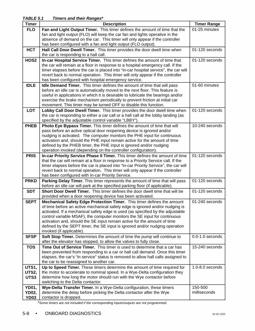
TABLE 5.1 Timers and their Ranges*Timer Description Timer Range
• ONBOARD DIAGNOSTICS 42-02-10205-8
FLO Fan and Light Output Timer. This timer defines the amount of time that thefan and light output (FLO) will keep the car fan and lights operative in theabsence of demand on the car. This timer will only appear if the controllerhas been configured with a fan and light output (FLO output).
01-25 minutes
HCT Hall Call Door Dwell Timer. This timer provides the door dwell time whenthe car is responding to a hall call.
01-120 seconds
HOS2 In-car Hospital Service Timer. This timer defines the amount of time thatthe car will remain at a floor in response to a hospital emergency call. If thetimer elapses before the car is placed into “in-car hospital service”, the car willrevert back to normal operation. This timer will only appear if the controllerhas been configured with hospital emergency service.
01-120 seconds
IDLE Idle Demand Timer. This timer defines the amount of time that will passbefore an idle car is automatically moved to the next floor. This feature isuseful in applications in which it is desirable to lubricate the bearings and/orexercise the brake mechanism periodically to prevent friction at initial carmovement. This timer may be turned OFF to disable this function.
01-60 minutes
LOT Lobby Call Door Dwell Timer. This timer provides the door dwell time whenthe car is responding to either a car call or a hall call at the lobby landing (asspecified by the adjustable control variable “LBBY”).
01-120 seconds
PHEB Photo Eye Bypass Timer. This timer defines the amount of time that willpass before an active optical door reopening device is ignored and/ornudging is activated. The computer monitors the PHE input for continuousactivation and, should the PHE input remain active for the amount of timedefined by the PHEB timer, the PHE input is ignored and/or nudgingoperation invoked (depending on the controller configuration).
10-240 seconds
PRIS In-car Priority Service Phase II Timer. This timer defines the amount of timethat the car will remain at a floor in response to a Priority Service call. If thetimer elapses before the car is placed into “In-car Priority Service”, the car willrevert back to normal operation. This timer will only appear if the controllerhas been configured with In-car Priority Service.
01-120 seconds
PRKD Parking Delay Timer. This timer represents the amount of time that will passbefore an idle car will park at the specified parking floor (if applicable).
01-120 seconds
SDT Short Door Dwell Timer. This timer defines the door dwell time that will beprovided when a door reopening device has been activated.
01-120 seconds
SEPT Mechanical Safety Edge Protection Timer. This timer defines the amountof time before an active mechanical safety edge is ignored and/or nudging isactivated. If a mechanical safety edge is used (as specified by the adjustablecontrol variable MSAF), the computer monitors the SE input for continuousactivation and, should the SE input remain active for the amount of timedefined by the SEPT timer, the SE input is ignored and/or nudging operationinvoked (if applicable).
01-240 seconds
SFSP Soft Stop Timer. Determines the amount of time the pump will continue toafter the elevator has stopped, to allow the valves to fully close.
0.0-1.0 seconds
TOS Time Out of Service Timer. This timer is used to determine that a car hasbeen prevented from responding to a car or hall call demand. Once this timerelapses, the car’s “in service” status is removed to allow hall calls assigned tothe car to be reassigned to another car.
15-240 seconds
UTS1,UTS2,UTS3
Up to Speed Timer. These timers determine the amount of time required forthe motor to accelerate to nominal speed. In a Wye-Delta configuration theydetermine how long the motor should run with the Wye contactor beforeswitching to the Delta contactor.
1.0-8.0 seconds
YD01,YD02,YD03
Wye-Delta Transfer Timer. In a Wye-Delta configuration, these timersdetermine the delay before picking the Delta contactor after the Wyecontactor is dropped.
150-500milliseconds
*Some timers are not included if the corresponding inputs/outputs are not programmed.

42-02-1020 ONBOARD DIAGNOSTICS • 5-9
5.2.4 SETTING THE REAL TIME CLOCK
To adjust the real time clock, set the switches as shown. The F4 function switch is used toaccess the clock parameters located on the Main Processor board.
Placing the F4 switch in the ON (up) position causes the alphanumeric display to show thecurrent year. The following table lists all the clock parameters and their adjustment ranges.
TABLE 5.2 Clock Parameters and their Ranges
Parameter Range Parameter RangeYEAR 00 - 99 DATE 01 - 31
MONTH 01 - 12 HOUR 00 - 23DAY MON. - SUN. MIN (MINUTE) 00 - 59
Press the N pushbutton to select the next parameter. Constant pressure on the N pushbuttoncauses the display to scroll through all of the real time clock parameters. Once a parameter hasbeen selected, the value can be changed by pressing the S pushbutton. Constant pressure onthe S pushbutton increases the value by one, until the value reaches the upper limit, at whichpoint it automatically starts over from the lower limit. Release the S pushbutton when thedesired value is displayed. The new value is saved immediately. Return the F4 switch to theOFF (down) position to exit the clock parameter adjustment menu.
5.2.5 ALPHANUMERIC DISPLAY - VIEWING THE MP /MP2 INTERNAL FLAGS / INPUTS
This function is used to display the status of many of the input/output and internally generatedflags related to the MC-MP-1ES or MC-MP2 computer. To access these flags, set the switchesas shown.
MC-MP-1ES Flags - With the MC-MP-1ES software, after moving the F5 switch to the ON (up)position, the alphanumeric display shows the last selected flag and status, in this case ALT

• ONBOARD DIAGNOSTICS 42-02-10205-10
OFF. The first word (ALT) is the abbreviated name for the Alternate Service flag. The secondword (OFF) is the status of the flag. For a listing of these flags, see Table 5.9.
To select a flag, press the N pushbutton until the first letter of the flag displayed is the sameas the first letter of the desired flag. Release the N pushbutton and press the S pushbutton untilthe desired flag is displayed. The flag’s current status, ON or OFF, is displayed.
MC-MP2 Flags - With the MC-MP2 software, after moving the F5 switch to the ON position,the alphanumeric display scrolls the message FLAGS STATUS... and then displaysabbreviation and status of the first available flag beginning with the letter A. Table 5.9 provides a listing of the available flags. To select a flag, press the N pushbutton untilthe first letter of the flag displayed is the same as the first letter of the desired flag. Release theN pushbutton and press the S pushbutton until the desired flag is displayed. The flag’sabbreviation and current status is displayed (0 = OFF, 1 = ON).
MC-MP2 Inputs - With the MC-MP2 software the status of many system inputs may be viewedon the alphanumeric display. To view the inputs, the F5 switch plus various additional switchesmust be placed in the ON (up) position as follows:
• F5, A9 HC-PIO board inputs• F5, A10 HC-RD board inputs• F5, A9, A10 HC-IOX / HC-I4O board inputs• F5, A11 HC-CIO board inputs• F5, A9, A11 MC-NC board inputs
Press the N pushbutton to scroll through the inputs available for this job. They are displayedin the order they are arranged on the board. The abbreviation and status of each input isdisplayed (0 = OFF, 1 = ON).
5.2.6 RESETTING THE MC-CGP PARAMETERS
When an MC-CGP-4(8) Communication Processor Board or EPROM are changed it may benecessary to reset the CGP parameters to their default values. This can be done using theoptional CRT terminal or via the Computer Swing Panel.
Using the optional CRT terminal - The optional CRT terminal connected to the local carcontroller may be used to reset the CGP parameters using ODPC Reset CGP Parameters onthe General (Shift F1) screen. For instructions on using the CRT terminal, refer to the sectionin the Computer Peripherals Manual, MCE part # 42-02-CP00 titled Using the CRT Terminal.
Using the Computer Swing Panel - The CGP parameters can be reset to their default valuesusing the Computer Swing Panel. Set the toggle switches as shown, then press and hold boththe N and S pushbuttons in at the same time for about five seconds.

42-02-1020 ONBOARD DIAGNOSTICS • 5-11
5.3 SYSTEM MODE (EOD)
System Mode provides a level of security (if programmed) so that an unauthorized personcannot modify or change the system parameters either intentionally or by mistake. To enter theSystem Mode, set the switches as shown.
With the F7 switch in the ON position, the alphanumeric display shows PASSWORD. Set theA1 - A8 switches to the password value. If no password has been programmed for this job(which is normally the case), set A1 - A8 to OFF (down).
Press the S pushbutton for ½ second. The alphanumeric display changes to SYSTEM. Whilein System Mode, the group of eight vertical status LEDs scan from bottom to top indicating thatSystem Mode is active. If no function switch is moved or pushbutton is pressed for a period oftwo minutes, the computer will automatically exit from System Mode and go into the NormalMode of operation. Placing the F7 switch in the OFF (down) position also causes the EOD toexit the System Mode.
In System Mode, the Function Keys are used to access and set the following systemparameters:
C F1 - Communication Port Settings (see Section 5.3.1)C F2 - Internal use onlyC F3 - Security Codes (see Section 5.3.2)C F4 - Not usedC F5 - MSK: Master Software Key (Simplex only) (see Section 5.3.3)C F6 - Software Options - adjustable control variables (see Section 5.3.4)C F7 - Turns System Mode ON and OFFC A8 - Setting and Resetting the Passcode Option (see Section 5.3.5)

• ONBOARD DIAGNOSTICS 42-02-10205-12
5.3.1 PROGRAMMING THE COMMUNICATION PORTS
The communication ports are field programmable through the Computer Swing Panel'sEnhanced On-Board Diagnostics (EOD). MCE's Computer Peripherals Manual coversconnecting a CRT terminal to a COM Port on the MC-RS Communication Interface board andset-up of the CRT terminal.
The communication ports were programmed (at the factory) for the original hardware, basedon customer-provided information. It may be necessary to reprogram a communication portwhen changing from a monochrome to a color CRT, adding a lobby CRT or CRT with keyboardor adding a modem. The new hardware will not work correctly until the communication port isreprogrammed.
To reconfigure the communication port, enter the System Mode as described at the beginningof Section 5.3 and set the switches as shown.
When the F1 switch is placed in the ON (up) position, the alphanumeric display shows thefollowing scrolling message: COMPORT MENU PRESS S TO START. Press the Spushbutton for ½ second and the display will show the current setting for the first item on theCOM port menu, in this case 1M=SCBL. The 1M stands for COM Port 1 Media and SCBLstands for Serial Cable (see Tables 5.3 and 5.4) To change a communication port setting,press the N pushbutton to scroll through the Communication Port Menu until the desired itemis shown on the alphanumeric display. Table 5.3 lists the items on the COM port menu.
CHANGING THE MEDIA SETTING - To change the media setting for COM Port #2, press theN pushbutton to scroll through the items on the Communications Port Menu (see Table 5.3) andrelease N when 2M is displayed. Then press the S pushbutton to scroll through the Media Menu(see Table 5.4). Release S when the desired media is displayed. After selecting the desiredmedia, press N to again scroll through the Communications Port Menu.
CHANGING THE DEVICE SETTING - To change the device setting for COM Port #2, pressthe N pushbutton to scroll through the Communications Port Menu and release N when 2D isdisplayed. Then press the S pushbutton to scroll through the Device Menu (see Table 5.5).Release S when the desired device is displayed. After selecting the desired device, press N toagain scroll through the Communications Port Menu.
SAVING THE CHANGES - When you have finished making changes, press the N pushbuttonuntil, SAVE?N/S is displayed. Pressing S will save the changes and SAVED... will be displayed.If N is pressed the program will continue to scroll through the Communications Port Menu. Toexit the Communications Port Menu, place the F1 switch in the OFF (down) position. If you exitthe Communication Port Menu without choosing SAVE?N/S and pressing S, any changes madeto settings will be ignored.

42-02-1020 ONBOARD DIAGNOSTICS • 5-13
TABLE 5.3 Communication Port Menu
EOD Display Description
NO COM No COM port option has been enabled1M COM Port 1 Media1D COM Port 1 Device2M COM Port 2 Media2D COM Port 2 Device3M COM Port 3 Media3D COM Port 3 Device4M COM Port 4 Media4D COM Port 4 Device
SAVE?N/S Save the changes? N for no or continue, S for save
TABLE 5.4 Media Menu
EOD Display Description
NONE NO MEDIA - Select when removing a computer terminal from a port.SCBL SERIAL CABLE - Select when setting up a CRT/terminal with a keyboard.LDRV LINE DRIVER - Used when setting up a CRT at a distance over 40 feet.MODM MODEM - Select when attaching a modem to a computer.
TABLE 5.5 Device Menu
EOD Display Description
NONE No Device
CRTMK Use for these terminals or emulators with keyboard (Link MC5, Wyse WY-325ES, Esprit 250C Emulator or ADDS 260LF Emulator)
CRTM Use for these terminals or emulators without keyboard (Link MC5, Wyse WY-325ES, Esprit 250C Emulator or ADDS 260LF Emulator)
PC Personal Computer with CMS / MSD
PCGD Personal Computer Graphic Display (no longer used)
CRTCK Use for these terminals with keyboard (Link MC-70, Wyse WY-370)
CRTC Use for these terminals without keyboard (Link MC-70, Wyse WY-370)

• ONBOARD DIAGNOSTICS 42-02-10205-14
5.3.2 VIEWING AND CHANGING THE SECURITY CODES
For jobs with the MCE SECURITY, either Basic Security or Basic Security with CRT, thisfunction allows the security codes to be viewed or changed. If the job does not have MCESECURITY, the alphanumeric display will show NOT USED.
With MCE's Basic Security, the Building Security Input (BSI) is used to turn security ON andOFF. Refer to the job prints to find the BSI input. When Security is ON, all car calls arescreened by the computer and become registered only if: (1) the call is to a floor that is not asecured floor, or (2) the floor is a secured floor and its Security Code is correctly entered within10 seconds.
With MCE's Basic Security with CRT Option, additional programming options are available viathe CRT terminal. Refer to MCE's Elevator Security User's Guide, part # 42-02-S024 foradditional information and programming instructions. For both Basic Security and BasicSecurity with CRT Option, the security codes for each floor are programmed as describedbelow.
The Security Codes are viewed and changed using the Computer Swing Panel. To view andchange the security codes, place the F3 Switch in the On or up position while in "System"mode. Not all elevator systems are equipped with the SECURITY option. If the system doesnot have BASIC SECURITY, the Alphanumeric Display will show "NOT USED" when the F3switch is turned On.
The security code for each floor may consist of from one to eight characters, where eachcharacter is one of the floor buttons found in the elevator car. Each floor may have a differentlength code. Table 5.6, Changing Floor Security Status and Security Code, describes the stepsrequired to view and change a floor’s security code. A floor can not be Secured unless aSecurity Code has been programed.
The Appendix, Security Information and Operation in the Elevator Security User's Guide,provides instructions for elevator passengers who will be using the elevator while Security isON. Space has been provided for listing the security codes for each floor.

42-02-1020 ONBOARD DIAGNOSTICS • 5-15
TABLE 5.6 Changing the Floor Security Status and Security Code
Switch Explanation Alphanumeric Display
Step 1
F3 On
To begin, display the 1st floor’s status
While in the System mode, turn functionswitch F3 On, “Up”.
Example:
B = basementNSCR = not secured
Step 2
Press N
To display another floor’s security status
Steps to the next floor’s security status.Press N again for the next floor, etc.
Example:
1 = floor #1SCRD = secured
Step 3
Press S
To select a floor to view or change a code
With the floor’s security status displayed,press S. The first character of the floor’ssecurity code is then displayed.
Example:
For floor 2, the first character in thecode is 3.
Step 4
Press S
To change a code character
Steps through the available codecharacters. When the desired character isdisplayed, go to Step 5.
Example :
For floor 2, the first security characteris now 5.
Step 5
Press N
To display the next code character
Steps to the next character in the code. To change more characters, repeat steps4 and 5.
The last character of a code must be theword END if the code is less than eightcharacters long.
Example 1:
For floor 2, the second character inthe code is 4.
Example 2:
For floor 2, the first character in thesecurity code is the word END. Floor2 is unsecured.
Step 6
Press N
To end and save
If END is chosen as a code character or ifthis is the eighth character, when N ispressed the computer saves the code anddisplays the current floor’s security status.To view or change the code for anotherfloor, return to step 2.
Example :
If END was chosen for first character,this floor has no security code and isunsecured. Using END for any othercharacter just ends that code, but thefloor is still secured.
F3 and F7switches
Off, downposition
To exit System mode
Every security code must end with theword END or be 8 characters long. If not,the processor remains in System mode.
Example:
The time displayed
B N S C R
1 S C R D
2 1 = 3
2 1 = 5
2 2 = 4
2 1 = E N D
2 N S C R
1 1 : 0 4 : 2 7

• ONBOARD DIAGNOSTICS 42-02-10205-16
5.3.3 SETTING MSK: MASTER SOFTWARE KEY
On a simplex car, the Master Software Key is used in conjunction with the Basic Security withCRT Option. To view or change MSK, log into System Mode as described at the beginning ofSection 5.3 and then place the F5 switch in the ON (Up) position. If this is not a simplex car orif this job does not have the Basic Security - CRT Option enabled, the alphanumeric display willshow NOT USED. Additional information about the Master Software Key (MSK) can be foundin MCE's Elevator Security User's Guide, Section 3, Basic Security with CRT - Swing Panel.
5.3.4 SETTING THE SOFTWARE OPTIONS - ADJUSTABLE CONTROL VARIABLES
Table 5.7 provides a listing of the software options - adjustable control variables. Not all of theoptions are available on all controllers. To view or set the adjustable control variables, log intoSystem Mode as described at the beginning of Section 5.3 and place the F6 switch in the ON(Up) position.
The first available variable will be shown on the display. Press the S pushbutton to change thesetting. Press the N pushbutton to scroll to the next available variable. Table 5.7 lists thevariables in alphabetic order, not in the order in which they are displayed on the controller.
TABLE 5.7 Software Options
VARIABLE NAME DEFINITION
AFR Alternate Fire Floor Recall Determine the designated recall floor for alternate Fire Service Operation.
AFR2 Second Alternate FireFloor Recall
Determine the designated recall floor for the second alternate Fire Service operation(Detroit Fire code).
AGNG Alternate Gong Option Causes an arrival lantern to be illuminated whenever the car's doors are open at anon-lobby landing. In the absence of actual call demand, the direction selected is areflection of the car's last direction of travel. If the car is located at a terminal landing,the appropriate lantern will be illuminated.
APP1 Alternate Primary (lower)Parking Floor
When on, the car will no longer park at the original parking floor (PPF). Instead the carwill park at the first alternate parking floor specified by the landing stored in thisvariable.
APP2 Alternate Primary (lower)Parking Floor #2
When ON, the car will no longer park at the original parking floor (PPF). Instead thecar will park at the second alternate parking floor specified by the landing stored in thisvariable.
ASP1 Alternate Secondary(upper) Parking Floor
When ON, the car will no longer park at the original secondary parking floor (SPF).Instead the car will park at the secondary parking floor specified by the landing storedin this variable. This variable is only available on a duplex system.
ASP2 Alternate Secondary(upper) Parking Floor #2
When ON, the car will no longer park at the original secondary parking floor (SPF).Instead the car will park at the secondary parking floor specified by the landing storedin this variable. This variable is only available on a duplex system.
CCBC Cancel Car Call BehindCar Option
If ON, and if the car has a direction arrow (SUA/SDA), no car calls can be registeredbehind the car's current position. For example, if a car is at the fifth floor, movingdown, then no car calls can be registered for any floors above the fifth floor.
CNID Car Network ID (A thru L) The Car Network ID identifies this controller to the Group Supervisor.
CPPB Constant/MomentaryPressure PhotoEye/Safety Edge Bypass
This option, when turned “OFF”, will disable photo eye/safety edge bypass logic forcars that are on Independent Service, Attendant Service, Hospital Service Phase 2,and any other non-automatic door closing conditions (CPCLOSE, MPCLOSE, etc.).
CSAR CSA Redundancy CheckOption
When ON, CSA redundancy checking logic is invoked. When OFF, the LSR, CNP andUDF inputs are ignored, and CSA redundancy checking logic is not performed.
DCFL Door Close Front Latch Maintains the Door Close Function on the front doors continuously as long as a dooropen command is absent.
DCRL Door Close Rear Latch Maintains the Door Close Function on the rear doors continuously as long as a dooropen command is absent.

TABLE 5.7 Software Options
VARIABLE NAME DEFINITION
42-02-1020 ONBOARD DIAGNOSTICS • 5-17
DDOP Double Ding on DownOption
When ON, the gong output dings twice for down direction travel and once for updirection travel. If OFF, the gong output will only ding once for both up and downdirection of travel.
DDPO Door Lock DirectionPreference Option
Causes the car to hold its direction preference until the doors are closed. When OFF,the car will be allowed to change direction preference with the doors open (when thehall call door time elapses).
DGNG Door Lock Gong Option Determines when the arrival gong outputs are activated. The arrival gong outputs areactivated after the doors begin to open. When OFF, the arrival gong outputs areactivated when the car steps into the floor. This option should be OFF when hallmounted arrival fixtures are used and turned ON when car-riding arrival fixtures areused.
DOFL Door Open Front Latch Maintains the Door Open Function on the front doors continuously as long as a doorclose command is absent.
DORL Door Open Rear Latch Maintains the Door Open Function on the rear doors continuously as long as a doorclose command is absent.
HREO Reopen doors with hallbutton
If enabled, this option will allow the activation of a hall call button to cause a car’sdoors to reopen (if in the process of closing). If the option is turned OFF, the doors willnot reopen if the doors are closing and a car call has been registered for that car.
KCE Keyboard Control ofElevators
MCE’s Elevator Central Monitoring System software, CMS for Windows, allowsmonitoring of elevators and control of certain elevator functions using a PC. The CMSoption, KCE can be enabled or disabled at the local car or group level by turning thecontroller’s Adjustable Control Variable, KCE, ON or OFF. Changing the KCE settingin the individual car’s controller affects only that car. Changing the KCE setting in theGroup controller affects all of the cars in that group. Consult the CMS for Windowsmanual for additional information.
LBBY Lobby Floor Determines the location of the lobby floor in the building.
LGNG Lobby Alternate GongOption
Causes an arrival lantern to be illuminated whenever the car's doors are open at thelobby landing. In the absence of actual call demand, the up direction lantern will beilluminated.
LLCC Light Load Call Cancel When the light load input (LLI) is ON, this variable sets the threshold above which anadditional car call will cause all previous calls to be canceled with the exception of thelast call entered in the system.
MFR Main Fire Floor Recall Determine the designated recall floor for main Fire Service operation.
MSAF Mechanical Safety Edge Determine if the car has Mechanical Safety Edge. This option must be turned ON if thecar has Mechanical Safety Edge, otherwise it should be OFF when an infrared detectoris used.
NPRE No Pre-opening Option When ON, prevents pre-opening of the doors on an approach to any landing. WhenOFF, the doors will start to open as soon as the car is 3" (76 mm) from level at thetarget floor.
PECC Anti-nuisance Call Cancel Sets the threshold for the number of car call stops without an interruption of the photoeye. If no photo eye interruption is detected when the car answers the fourth car call,the controller will cancel any additional car calls registered in the system. This functionis normally referred to as anti-nuisance.
PHEP Photo Eye Protection When this variable is set to ON, it will prevent the photo eye from ever being bypassedexcept on Fire Service. When set to OFF, this option will enable the stuck photo eyeprotection logic and the photo eye will be bypassed after the car times out of service.This option must be turned ON for all jobs that use the PHE input for the door hold keyswitch.
PPF Primary (lower) ParkingFloor
Determines where the car will park in the absence of call demand. In a duplex system,this variable must be programmed as one of the landings in the building, and is set atthe factory before shipment. In group systems, this variable only takes effect when thecar is operating independently of the group supervisor or if there is a loss ofcommunication with the group supervisor.
RCCD Reversal CCD Option When ON, all registered car calls are canceled when the car reverses direction.
SPF Secondary (upper)Parking Floor
Determines which landing is used as the second parking floor. This variable is onlyavailable on a duplex system.

• ONBOARD DIAGNOSTICS 42-02-10205-18
5.3.5 LOAD WEIGHER LEARN OPERATION (CALIBRATION)
The load weigher (isolated platform or crosshead deflection) provides a signal that correspondsto the perceived load. This signal is brought to the control system where it is conditioned,sampled and digitized, and the value is used to calculate the actual load inside the elevator.This load value is then used for logical operations such as anti-nuisance and hall call bypass.
With the isolated platform load weigher (MCE), the system simply learns the reference valuesof the empty and fully loaded car weight, which are then used to calculate the current load (asa percentage of full load). However, with the crosshead deflection load weigher (K-Tech), themagnitude of the signal generated by the load sensor represents the perceived load at thecrosshead, which includes the weight of the car itself, the load inside the car, the travelingcable, and any compensation cables that might be attached to the car. Therefore it isnecessary for the controller to use the measured load value in a calculation to determine theload inside the elevator (the raw load value cannot be used as is).
Due to the dynamics of the elevator system, the load represented by the traveling cable andcompensation cables will vary with the position of the car in the hoistway. The load weighingsystem accounts for these variances by performing a process which learns empty car and fullcar load values at each floor in the building. The load in the car can then be determined byreading the value at a given floor and, using the learned values for that floor, performing alinear interpolation to approximate the load inside the car (as a percentage of full load). Thecalculated load percentage is then used to initiate logical operations, i.e., hall call bypass at80% of capacity.
Logical operations that use the load information include: light load weighing (anti-nuisance),advance car dispatch (reduction of door dwell time), heavy load weighing (hall call bypass), andoverloaded car detection. Each threshold is user-programmable, and will determine when eachof these logical operations should be performed.
The measurement of the load will only take place when the car is stopped at a landing with thedoors open. This is the only time that we would anticipate a change in load upon which a logicaloperation should be initiated. The measurement is not taken when the car is running becausethe acceleration and deceleration of the car would be interpreted as a change in load.
Functional Description of Load Thresholds - The four load thresholds are:
C LLW (Light load weigher threshold): This threshold value is used to define the load atwhich a limited number of car calls is to be registered. If the programmed number of carcalls is exceeded, all car calls will be canceled.
Example: LLW=20%. If the measured load in the car is less than 20%, the computer willonly allow a certain number of car calls to be registered (defined by a field-programmable value LLCC). If LLCC is programmed at a value of 3, the computer willonly allow 3 calls to be registered if the load is less than 20%. If a fourth call isregistered, all car calls will be canceled.
C DLW (Dispatch load weigher threshold): This threshold value is used to define the loadat which the lobby landing door timer is reduced. This threshold should be set to a value(defined in many specifications as 60%) at which it is appropriate to initiate the processof moving the car out of the lobby.
C HLW (Heavy load weigher threshold): This threshold value is used to define the loadvalue at which hall calls should be bypassed.

42-02-1020 ONBOARD DIAGNOSTICS • 5-19
C OLW (Overloaded car threshold): This threshold value is used to define the load valueat which it is considered unsafe to move the elevator. When this threshold is exceeded,the car will remain at the floor with doors open. Typically an application that requiresOLW will use some type of visual and/or audible indicator to alert elevator passengersthat the car is overloaded.
C OLW2 (Overloaded car threshold 2): When on Fire Service, this threshold value is usedinstead of the OLW value (see OLW above).
Learn Modes - With the isolated platform load weigher (MCE), the system simply learns thereference values of the empty and fully loaded car weight. However, with the crossheaddeflection load weigher (K-Tech), the system must learn the reference values of empty and fullyloaded car weight at each floor. This is necessary because the perceived load at the crossheadvaries with the position of the car in the hoistway due to the changing proportion of the travelingcable hanging beneath the car and the position of the compensation cables. Examples of thecauses fo load variance include:
• The position of the traveling cable will present a varying load (a changing proportion ofthe traveling cable hanging directly beneath the car).
• The position of the compensation cables will present a varying load (a changingproportion of the compensation cable hanging directly beneath the car). Note that thecompensation cables are intended to equalize the load at the motor sheave, not at thecrosshead.
• Variances in the alignment of the hoistway guide rails will present varying amounts ofresistance to elevator movement. An added amount of resistance or friction may resultin an increased perceived load at the crosshead.
The values learned for the empty car and full car at a particular floor are used to calculate theload when the car is positioned at that floor.
The Learn Process - The learn process consists of three functions:
C Learning the measured load value for an empty car at each landing.
C Learning the measured load value for a fully loaded car at each landing.
C Establishing the load thresholds which will initiate the logical operations.
Each of these functions can be performed separately. All three functions must be performedbefore the load weigher system will perform properly. To enter the learn function, the carmust be placed on Independent Service. If an independent service switch is available in thecar, use it. If not, the car can be placed on Independent Service by connecting a jumperbetween terminals 2 and 49 on the controller main relay board. A further option is to use theTEST/NORM switch on the SC-SB2K relay board, but this will electrically disconnect the dooropen relays, and is therefore not recommended.
5.3.5.1 GETTING INTO LOAD WEIGHER LEARN MODE
a. Enter the SYSTEM mode of operation on the Computer Swing Panel by following thesteps described at the beginning of Section 5.3.

• ONBOARD DIAGNOSTICS 42-02-10205-20
b. Once in SYSTEM mode, access the load weigher learn function by turning theDiagnostic On switch ON (the F7 switch should remain in the ON position). Thecomputer will respond with one of three scrolling messages:
C NOT USED - The software has not been configured to provide the “analog loadweighing function”. Contact MCE if you believe this to be in error.
C CAR NOT READY TO LEARN - Verify that the car has been placed onIndependent Service.
C PRESS N FOR K-TECH CROSSHEAD OR S FOR MCE PLATFORM... - Selectthe type of load weigher by pressing N for K-Tech crosshead deflection or S forMCE isolated platform load weigher.
The following message is then displayed:
C ANALOG LOAD WEIGHER LEARN FUNCTION...PRESS N TO CONTINUE -The system is ready to learn, you have successfully placed the elevator in “loadweigher learn mode”.
c. Once the elevator has successfully been placed in “load weigher learn mode” one orall three of the learn functions can be performed as described in sections to follow. Thesystem will display one of three main prompts:
C READY TO LEARN EMPTY CAR VALUES? PRESS S TO CONFIRM - Pressthe S push-button to begin this process. The car must be empty beforebeginning.
C READY TO LEARN FULL CAR VALUES? PRESS S TO CONFIRM - Press theS push-button to begin this process. Place the full load weights in the car beforebeginning.
C ADJUST THE LOAD THRESHOLDS? PRESS S TO CONFIRM - Press the Spush-button to adjust the load threshold values.
Press the N push-button to cycle through these three different prompts. To exit the loadweigher learn mode, turn the Diagnostic On function switch on the computer SwingPanel to OFF.
5.3.5.2 LEARNING THE EMPTY AND FULLY LOADED CAR VALUES
Learning the empty and loaded car values is an automated process that requires only that theappropriate load be present in the car before beginning each process. It is best to have twopersons available, one in the machine room at the elevator controller and one positionedat a floor with test weights available. The test weights must represent the full load value.
If the K-Tech crosshead deflection load weigher was selected, the learn process willautomatically run the car from floor to floor, stopping at each landing. The car will first travel tothe bottom landing, stop and pause there for a period of time. The car will then move in the UPdirection, stopping at each floor on the way to the car's highest landing served. Each time thecar stops at a landing a value is learned for that landing (either the empty or full load value).Once all floors have been learned, the car will automatically return to its point of origin andopen its doors. The learn process must be performed twice, once for empty car load and oncefor full car load.

42-02-1020 ONBOARD DIAGNOSTICS • 5-21
Learning the Empty Car Load Values:
a. With the system in “load weigher learn mode”, press the N push-button until thefollowing prompt is displayed: “READY TO LEARN EMPTY CAR VALUES? PRESS STO CONFIRM...”.
b. Verify that the car is empty.
c. Press the S push-button to begin the learn process.
1. When the S push-button is pressed, the car will automatically close its doorsand commence the learn operation. During this process, the doors will remainclosed and the car will not respond to car or hall call demand. If the K-Techcrosshead deflection load weigher was selected, the car will move to the bottomfloor, record the empty car value and then move up, stopping at each floor torecord the empty car value. When the top floor has been reached, the car willmove back to the floor at which the Load Weigher Learn procedure was begun.
2. During the learn process the computer will display the scrolling message:LEARNING EMPTY CAR VALUES...PRESS N TO ABORT.... The learn processmay be aborted by pressing the N push-button any time during the process.
3. Once the learn process is completed for the empty car, the computer will brieflydisplay the message: “EMPTY CAR LEARN PROCESS COMPLETED...”. Atthat time, the car should be positioned at the floor where the learn process wasbegun, with the doors fully open.
4. The computer will then display the message: “READY TO LEARN FULL CARVALUES? PRESS S TO CONFIRM...”. Refer to the next section if you wish tolearn the fully loaded car values. [Do not press the S push-button at thistime!]
Learning the Fully Loaded Car Load Values:
a. With the system in “load weigher learn mode”, press the N push-button until thefollowing prompt is displayed: “READY TO LEARN FULL CAR VALUES? PRESS S TOCONFIRM...”.
b. Using a car call, call the car to the floor where the test weights are located. Load thetest weights, that represent the full load value, into the car.
c. Once the test weights have been loaded, press the S push-button to begin this learnprocess. The process is identical to the empty car learn process described above. Thecomputer will display the scrolling message: “LEARNING FULL CAR VALUES...PRESSN TO ABORT...”.
1. The learn process may be aborted by pressing the N push-button any timeduring the process.
2. Once the learn process is completed for the fully loaded car, the computer willbriefly display the message: “FULL CAR LEARN PROCESS COMPLETED...”.At that time, the car should be positioned at the floor where the learn processbegan, with the doors fully open. The test weights may now be removed fromthe car.

• ONBOARD DIAGNOSTICS 42-02-10205-22
3. The computer will then display the message: “ADJUST THE LOAD WEIGHERTHRESHOLDS? PRESS S TO CONFIRM...”. Refer to the next section if youwish to adjust the load weigher threshold values.
5.3.5.3 ADJUSTING THE LOAD THRESHOLDS
The load thresholds are preset, at the MCE factory, to values based upon the job specification.However, these thresholds are user-adjustable and may be changed at any time. To adjustthese thresholds, enter the SYSTEM mode of operation as described at the beginning ofSection 5.3, and select the load weigher learn function. The car must be on IndependentService to enter the load weigher learn function.
a. With the system in the “load weigher learn mode”, press the N push-button until thecomputer responds with the scrolling message: “ADJUST THE LOAD WEIGHERTHRESHOLDS? PRESS S TO CONFIRM...”.
b. Press the S push-button to adjust the thresholds.
c. Once the S push-button is pushed, the computer will respond by displaying mnemonicsthat represent the load values. The value shown next to the mnemonic is the currentthreshold value for that parameter expressed as a percentage of the full load value.
Dispatching Threshold Typical Value Range
• LLW = light load (anti-nuisance) threshold 20% 0 - 40%
• DLW = dispatch load threshold 50% 20 - 80%
• HLW = heavy load (hall call bypass) threshold 80% 50 - 100%
• OLW = overloaded car threshold 105% 80 - 125%
• OLW2 = overloaded car threshold 2 125% 100 - 140%
d. Choose the parameter to be adjusted by pressing the N push-button. The mnemonicsand values will scroll as long as the N push-button is depressed.
e. The desired value may be adjusted by pressing the S push-button. The value will beincremented until the upper limit value is reached. The value will then roll over to thelower limit value. These limit values are predetermined at MCE, and must be modifiedwith an EPROM change, if necessary.
f. After the last parameter is displayed, pressing the N push-button will cause thecomputer to display the prompt: DONE ADJUSTING THRESHOLDS? PRESS S TOCONFIRM... At this prompt, pressing the S push-button will exit the thresholdadjustment function; pressing the N push-button will return the prompt to the firstthreshold parameter.
The thresholds can be set to the desired values, as a percentage of full load. Settingthe value to 00% will disable the corresponding function. Example: setting the HLWthreshold to 00% will disable the hall call bypass function.
Exiting the Load Weigher Learn Mode
Exit the load weigher learn mode by placing the Diagnostic On/Normal switch in the Normal(down) position. Exit System Mode of diagnostics by turning the F7 switch OFF (down).

42-02-1020 ONBOARD DIAGNOSTICS • 5-23
NOTE: PASSWORD is not the same as PASSCODE. The PASSWORD is usedto limit access to System Mode. The PASSCODE, when activated, requiresthat a passcode be set in order to run on any mode other than Inspection.
5.3.6 SETTING AND RESETTING THE PASSCODE OPTION (NOT ON ALL CONTROLLERS)
The Passcode Request option can be used to require that a passcode be entered in order torun the car on any mode of operation other then Inspection. If a passcode has not been pre-programmed for the controller, the Passcode Request option is not available and will notappear.
Upon power up, the message MP2 VERSION NUMBER: 8.xx.xx will scroll across thealphanumeric display. If a passcode has been pre-programmed and the Passcode Requestoption has been activated, the message PASSCODE REQUEST... is then scrolled. This meansa passcode is required in order to run the elevator on any mode other than Inspection.
In order to set the passcode (to run the car on Normal operation) or clear the passcode (toactivate the Passcode Request option), the controller must first be placed in System Mode asdescribed at the beginning of Section 5.3.
5.3.6.1 SETTING THE PASSCODE
Once in System Mode, place the A8 switch in the ON (up) position as shown.
The message PRESS -S- TO SET PASSCODE OR -N- TO CLEAR PASSCODE... will scrollacross the display. Press the S pushbutton. The message CODE 1 = 0 is displayed.
The passcode consists of eight alphanumeric characters. The display indicates the value ofcode character #1. Press the S pushbutton to change the value. Press the N pushbutton toselect the next passcode character. When the A1 switch is ON (up) the display will decrementwhen either N or S are pressed.

• ONBOARD DIAGNOSTICS 42-02-10205-24
When the eighth passcode character is displayed, pressing the N pushbutton causes thedisplay to change to SAVE? N/S. Press N continue setting / changing the passcode. Press Sto save the passcode. If the passcode is set correctly the display will show SAVED.... If thepasscode is not set correctly the message INVALID PASSCODE. PRESS N TO CONTINUEis scrolled across the display. Pressing N causes CODE1= (x) to be displayed so that thepasscode can be corrected.
Once the passcode is set correctly and saved, exit System Mode by placing the F7 and A8switches in the OFF (down) position. The car can then be run on Normal operation.
5.3.6.2 ACTIVATING THE PASSCODE REQUEST OPTION
The Passcode Request option can be re-activated by clearing the valid passcode setting. Toclear the passcode, enter System Mode as described in Section 0.1 and place the A8 switchin the ON (up) position. Press the N pushbutton while the message PRESS -S- TO SETPASSCODE OR -N- TO CLEAR PASSCODE... is being scrolled. The display changes toCLEARED. Exit System mode by placing the F7 and A8 switches in the OFF (down) position.The message PASSCODE REQUESTED... is scrolled across the display and the car is onlyallowed to run on Inspection operation.
5.4 DIAGNOSTIC MODE (EOD)
In the Diagnostic Mode, the A1 thru A8 switches allow the elevator mechanic to access theMC-MP or MC-MP2 computer memory locations. To access Diagnostic mode, set the switchesas shown.
5.4.1 VIEWING THE MC-MP or MC-MP2 COMPUTER FLAGS
The A1-A8 switches enable an elevator mechanic to look at the MC-MP (MP2) flags whentroubleshooting a problem. Figure 5.3 describes the procedure for viewing the computer flags,in this case at address 20H (selected from Table 5.9)

42-02-1020 ONBOARD DIAGNOSTICS • 5-25
GEDGEUSEDBCDOLDZPHEDOLM
MC-MP-1ES BOARD DIAGNOSTIC MODE ADDRESSES AND VARIABLE FLAGS
ComputerMemoryAddress
(Hex)Diagnostic On F1 A8.......A5 A4.......A1
20
Diagnostic IndicatorsLED On = variable flag is On or Active
8 7 6 5 4 3 2 1
Toggle Switches
DNmd 010
FIGURE 5.3 Viewing the flags at Address 20H (from Table 5.9)
In this example, address 20 has been selectedfrom Table 5.9 in the back of this section. TheDiagnostic On/Norm switch and the A6 switch areUP; all other A switches are down. The displayreads ADD.20H. The flags that can be viewed fromthis address are listed on the right. A complete listof these flags can be found in Table 5.8. Check theDiagnostic Indicators on the front of the SwingPanel. If an LED is ON, it means that flag is ON.For example, if Diagnostic Indicator #6 is ON, thismeans the Door Zone Input (DZ) is ON.
LED Flag Description
8 DOLM Door open limit memory flag
7 PHE Photo eye input
6 DZ Door zone input
5 DOL Door open limit input
4 DBC Door close button input
3 SE Safety edge input
2 GEU Gong enable up output
1 GED Gong enable down output
Table 5.8 provides a listing of the MC-MP (MP2) flags and the abbreviation assigned to eachflag. Tables 5.9, 5.10 and 5.11 show the memory address locations for the flags. Access aflag’s address by setting the A1 - A8 switches as shown in Table 5.9. Once an address hasbeen selected, the diagnostic indicators, on the front of the Swing Panel, show the status of theflags at that computer memory address. Table 5.9 shows the abbreviations for the flags in thecolumns Ø thru ß (corresponding to Diagnostic Indicators 1 thru 8) in each row.
ALTERNATE ADDRESS SELECTION METHOD - There is an alternate way of selecting thecomputer memory address, without using the A1-A8 switches. To do so, regardless of theposition of A1-A8 switches, press the N pushbutton. The alphanumeric display automaticallyreads ADD. 20H, which is the first diagnostic address for the MC-MP flags. The ComputerSwing Panel's Diagnostic Indicators show the contents of the address displayed. Constantpressure on the N pushbutton automatically increases the address shown on the alphanumericdisplay, and the state of the indicator lights changes respectively. Once the address reaches33H, it automatically goes back to 20H. Releasing the N pushbutton holds the last addressdisplayed on the alphanumeric display for an additional 3 seconds before changing the displayto reflect the address selected by the A1-A8 switches.
NOTE: MC-MP2 flags are more easily viewed in Normal mode - see Section 5.2.5Alphanumeric Display of MP2 flags.

• ONBOARD DIAGNOSTICS 42-02-10205-26
TABLE 5.8 MC-MP(2) Computer Variable FlagsABREV FULL NAME ABREV FULL NAMEADAC ADA Car Call Timer GED Gong Enable Down OutputADACR Rear ADA Car Call Timer GEU Gong Enable Up OutputADAH ADA Hall Call Timer H High Speed OutputADAHR Rear ADA Hall Call Timer HCDX Hall Call DisconnectALT Alternate Service HCR Hall Call Reject ATSF Attendant Service Function HCT Hall Call Door Time BFD Bottom Floor Demand HLD Hold Input Fire Phase IIBSI Building Security Input HLI Heavy Load InputCC Car Call HLW Heavy Load WeigherCCA Car Call Above HML Home Landing Select InputCCB Car Call Below HSEL Hospital Emergency SelectCCC Car Call Cancel HYD/TRC 1 = Hydro, 0 = TractionCCD Car Call Disconnect IN Inspection or Access InputCCT Car Call Door Time IND Independent Service InputCD Car Done ISR In Service and ReadyCD 3 Third Bit in Absolute PI Code ISRT In Service Truly CD4 Fourth Bit in Absolute PI Code ISV In Service CSB Car Stop Switch Bypass Output LD Level Down InputCTL Car to Lobby Input LFP Lower Floor Parking CTLF Car to Lobby Function Flag LLI Light Load InputDBC Door Button Close Input LLW Light Load WeigherDC Down Call LOT Lobby Door Time DCA Down Call Above LU Level Up InputDCB Down Call Below MLT Motor Limit Timer DCC Door Close Complete MLTDO MLT Door Open FlagDCF Door Close Function Output MLTP MLT Pilot Flag (Internal)DCL Door Close Limit NUDG Nudging OutputDCLR Rear Door Close Limit PFG Passing Floor GongDCLC Door Closed Contact Input PHE Photo Eye InputDCLCR Rear Door Closed Contact Input PK Parking DCP Door Closed Power Output PTI Power Transfer InputDDP Down Direction Preference RUN Run DHO Door Hold Open SAF Safety String InputDLK Door Lock Input SD Supervisory Down DMD Demand Down SDA Down Direction Arrow OutputDMU Demand Up SDT Short Door Time DNDO Down Direction Output SE Safety Edge InputDNS Down Direction Sense Input SLV Slaved DOF Door Open Function Output SP1 Spare Input #1DOI Door Open Intent SP2 Spare Input #2DOL Door Open Limit Input SST Soft Stop Timer FlagDOLM Door Open Limit Memory STC Stepping Complete DPM Door Position Monitor STD Step Down InputDPMR Rear Door Position Monitor STU Step Up InputDSD Down Slow Down Input SU Supervisory Up DSH Door Shortening (Car Call Button Pushed) SUA Up Direction Arrow OutputDSHT Door Shortening (Final) SUD Up or Down Direction InputDZ Door Zone Input TFD Top Floor DemandDZORDZ Door Zone or Rear Door Zone TOS Timed Out of Service ECRN Emergency Power Running Car UC Up Call EPI Emergency Power Input UCA Up Call Above EPR Emergency Power Return Function UCB Up Call Below ESSH Elevator Shutdown Switch Flag UDP Up Direction PreferenceESSI Elevator Shutdown Switch Input UFP Upper Floor Parking EXMLT Bottom Floor Recall Input UPDO Up Direction OutputFCS Fire Phase II Input UPS Up Direction Sense InputFRA Alternate Fire Phase I Input USD Up Slow Down InputFRC Fire Phase II VCA Viscosity Control ActiveFRM Fire Service Phase I VCI Viscosity Control InputFRS Fire Phase I Input VLT Valve Limit Timer FlagFWI Fire Warning Indicator Output WLD Wildop Inhibit Input

42-02-1020 ONBOARD DIAGNOSTICS • 5-27
GED
DOI
SDT
LOT
STU
UDP
CCA
RUN
ISRT
FRC
TFD
ALT
PFG
EP1
ADAC
DCLC
GEU
DHO
CCT
STD
FWI
PK
UCA
DSH
ISV
FRAS
USD
HML
EP1
DCL
ADAH
DPM
SE
HCT
NUDG
UPS
EXMLT
LU
DCA
CCD
FRSS
SUA
HSEL
CTL
ESSI
DBC
DCC
DNS
HLI
IN
UPDO
DMU
H
HCDX
FRM
SU
ISR
CTLF
ESSH
DOL
CC
DSHT
CSB
FRS
HLW
IND
DDP
CCB
SST
HCR
BFD
SLV
HLI
LLI
CD3
ADACR
DCLCR
DZ
UC
DOF
FCS
SP1
VCA
DCLC
UCB
VLT
SAF
DSD
LLW
ECRN
DCLR
ADAHR
DPMR
PHE
DC
DCP
FRA
SP2
UFP
DLK
LD
DCB
MLT
STC
SDA
BSI
CCC
HLD
DOLM
DCF
VCI
LFP
SUD
DNDO
DMD
TOS
SD
WLD
PTI
EPR
MC-MP(2) BOARD DIAGNOSTIC MODE ADDRESSES AND VARIABLE FLAGS*
ComputerMemoryAddress
(Hex) Diagnostic On F1 A8.......A5 A4.......A1
20
21
22
23
24
25
26
27
28
29
2A
2B
2C
2D
2E
2F
30
31
32
33
3B**
3F**
48**
* for Hydraulic Controllers that are part of a group ** MC-MP2 Ver. 8.0 or later software
Diagnostic IndicatorsLED On = variable flag is On or Active
8
Toggle Switches
DZORDZ
DNmd 035
7 6 5 4 3 2 1
TABLE 5.9 MC-MP(2) Diagnostic Mode Addresses and Computer Variable Flags (Local)

• ONBOARD DIAGNOSTICS 42-02-10205-28
GED
DOI
SDT
DSHT
STU
YSIM
LLI
UDP
CCA
RUN
ISRT
FRC
TFD
EPR
PTS
ALT
PUSD
PUSD
ADAC
DCLC
GEU
DHO
CCT
STD
FWI
PK
UCA
DSH
ISV
USD
CD
PTR
HML
EQN
EQN
DCL
ADAH
DPM
MLTDO
SE
HCT
NUDG
UPS
LU
DCA
REL
CCD
SUA
ECRN
YRQ
EPI
ESTE
ESTE
MLTP
DBC
DCC
DNS
IN
UPDO
DMU
H
HCDX
FRM
SU
ISR
EPS
EDS
EDS
EXMLT
DOL
CC
LOT
CSB
FRS
HLI
IND
DDP
CCB
MGR
HCR
BFD
ATSF
SLV
EQA
ADACR
DCLCR
VLT
DZ
UC
DOF
HSEL
FCS
HLW
EQI
UCB
PSTX
SAF
DSD
EQA
EPR
CWI
CWI
DCLR
ADAHR
DPMR
SST
PHE
DC
DCP
FRA
UFP
DLK
LD
DCB
MLT
STC
SDA
EPI
CBC
CBC
CWIL
VCA
DOLM
DCF
LFP
LLW
DNDO
DMD
TOS
SD
HLD
HLD
CAC
CAC
VCI
MC-MP(2) DIAGNOSTIC MODE ADDRESSES AND COMPUTER VARIABLE FLAGS
ComputerMemoryAddress
(Hex)Diagnostic On F1 A8.......A5 A4.......A1
20
21
22
23
24
25
26
27
28
29
2A
2B
2C
2D
2E
2F*
2F
30
32*
32
33
3B**
3F**
48**
4F**
* Hydraulic Simpex Ver. 3.59 or earlier software ** MC-MP2 Ver. 8.0 or later software.
Diagnostic IndicatorsLED On = variable flag is On or Active
8
Toggle Switches
INT/DCLC
DZORDZ
DELSIM
DNmd 034
1234567
HYD 1TRC O
TABLE 5.10 MC-MP(2) Diagnostic Mode Addresses and Computer Variable Flags (Simplex)

42-02-1020 ONBOARD DIAGNOSTICS • 5-29
GEDR
DOIR
SDTR
GEDR
DOIR
SDTR
GEUR
DHOR
CCTR
GEUR
DHOR
CCTR
SER
HCTR
NUDGR
SER
HCTR
NUDGR
DBCR
DCCR
DBCR
DCCR
DOLR
CCR
DSHTR
DOLR
CCR
DSHTR
DZR
UCR
DOFR
LOTR
DZR
UCR
DOFR
LOTR
PHER
DCR
DCPR
PHER
DCR
DCPR
DOLMR
DCFR
DOLMR
DCFR
MC-MP-x DIAGNOSTIC MODE REAR DOOR ADDRESSES AND VARIABLE FLAGS*
ComputerMemoryAddress
(Hex)Diagnostic On F1 A8.......A5 A4.......A1
10
11
12
13
14**
15**
16**
17**
Diagnostic IndicatorsLED On = variable flag is On or Active
8 7 6 5 4 3 2 1
Toggle Switches
* for Hydraulic Controllers, Simplex and Duplex** Car B of a single computer Duplex
GEDR
DOIR
SDTR
LOTR
GEUR
DHOR
CCTR
SER
HCTR
NUDGR
DBCR
DCCR
DOLR
CCR
DSHTR
DZR
UCR
DOFR
PHER
DCR
DCPR
DOLMR
DCFR
MC-MP-x DIAGNlOSTIC MODE REAR DOOR ADDRESSES AND VARIABLE FLAGS*
ComputerMemoryAddress
(Hex)Diagnostic On F1 A8.......A5 A4.......A1
10
11
12
13
Diagnostic IndicatorsLED On = variable flag is On or Active
8 7 6 5 4 3 2 1
Toggle Switches
DNmd 008* for Hydraulic Controllers that are part of a multi-car group
TABLE 5.11 MC-MP Diagnostic Mode Rear Door Addresses and Computer Variable Flags

• ONBOARD DIAGNOSTICS 42-02-10205-30
5.4.2 VIEWING AND ENTERING CALLS
This function allows the user to view all the calls registered per floor, and to enter calls asdesired. To view or enter calls, set the switches as shown.
FIGURE 5.4 Viewing and Entering Hall & Car Calls via the EOD
Diagnostic Indicatorsshow current calls
Diagnostic Indicators
ß Þ Ý Ü Û Ú Ù Ø
Call type ,
HallCallUP
Rear
HallCallUP
Front
HallCall
DOWN
Rear
HallCall
DOWN
Front
CarCallRear
CarCall
Front
To register calls, turnthe address switchON and press “S”
A8 A7 A6 A5 A4 A3 A2 A1
Address Switches
VIEWING CALLS - With the F4 switch in the ON position, the alphanumeric display showsFLOOR 01 and the Diagnostic Indicators light up with the calls that have been registered. Theformat for the call indication is shown in Figure 5.4. To advance the floor number press the Npushbutton. The Diagnostic Indicator LEDs will show the calls registered for the floor shown inthe alphanumeric display. When the top floor number is displayed, pressing N will cause thedisplay to cycle to the bottom floor.
ENTERING CALLS - To enter calls, select the desired floor as described above. Use the A1-A8switches to select the type of call to enter (see Figure 5.4). For example, set the A1 switch upto register a front car call. Then press and hold the S pushbutton until the call has beenregistered. Notes: (1) A call type which does not exist in the system cannot be entered, and (2)if this car is part of a group, only car calls can be entered.

42-02-1020 ONBOARD DIAGNOSTICS • 5-31
DOOR CLOSED LIMIT (DCL) AND REAR DOOR CLOSED LIMIT (DCLR) FLAGS
DCL INPUT - LOCAL HYDRO (MPOLHM software) - The memory flag for DCL is at internalmemory address 36 Hex, Diagnostic Indicator #4. Set the switches as shown.
Switches A5 thru A8 select the first digit (3) and A1 thru A4 select the last digit of the address(6). The Alphanumeric Display indicates that internal memory address 36 Hex is selected(ADD. 36H). Diagnostic Indicator #4 shows the status of the DCL input (LED ON = high, LEDOFF = low).
DCL INPUT - SIMPLEX/DUPLEX HYDRO (MPODH software) - The memory flag for DCL isat external memory address 0043 Hex, Diagnostic Indicator #2. Set the switches as shown.
Switch F2 selects external memory. Switches A13 and A14 select the first digit (0), A9 thru A12select the second digit (0), A5 thru A8 select the third digit (4) and A1 thru A4 select the lastdigit of the address (3). The Alphanumeric Display indicates that external memory address0043 Hex is selected (DA.0043H). Diagnostic Indicator #2 shows the status of the DCL input(LED ON = high, LED OFF = low).
DCLR INPUT - (all software) - The memory flag for DCLR is at external memory address0003 Hex, Diagnostic Indicator #6. Set the switches as shown.

42-02-1020 TROUBLESHOOTING • 6-1
SECTION 6TROUBLESHOOTING
6.0 GENERAL INFORMATION
MCE’s HMC-1000-HS controllers are equipped with certain features that can help fieldpersonnel speed up troubleshooting. Often the controller will indicate the nature of the problemin the form of a status or error message flashing on the Computer Swing Panel's Status and/orDiagnostic Indicators. The optional CRT terminal connected to either the car controller or theGroup Supervisor can provide useful diagnostics in the form of View Hoistway (F3 screen)messages and/or Special Events Calendar Fault Log (F7, 1 screen) messages. Table 6.4,Status and Error Messages, provides a complete listing of these messages, a description andrecommended corrective actions to be taken.
Troubleshooting often involves determining the status of specific inputs, outputs or computervariable flags. This information is stored in the controller's memory and the status of thesememory locations can be viewed using the Computer Swing Panel's Enhanced OnboardDiagnostics (EOD), described in Section 5. In addition, the system is designed so that tracingsignals from the field wires onto various boards and into the computer can be achieved withoutthe need for mechanical removal of any components or for rear access to the boards.
The troubleshooting section is arranged as follows:
Troubleshooting Topic: Go to:
Status and Error Messages table and look-up table for the MC-MPDiagnostic Indicator, scrolling and F3 screen messages.
Section 6.1
How to use the Special Events Calendar and setup for reportingemergency messages to a PC running CMS software.
Section 6.2
Using the Controller Diagnostics screens Section 6.3
Troubleshooting Car Operation Control (COC), Door Logic, Call Logic,and Quick References for the HC-PI/O and HC-CI/O boards.
Section 6.4
PC Board Quick References Section 6.5
Using the MLT / VLT Data Trap Section 6.6
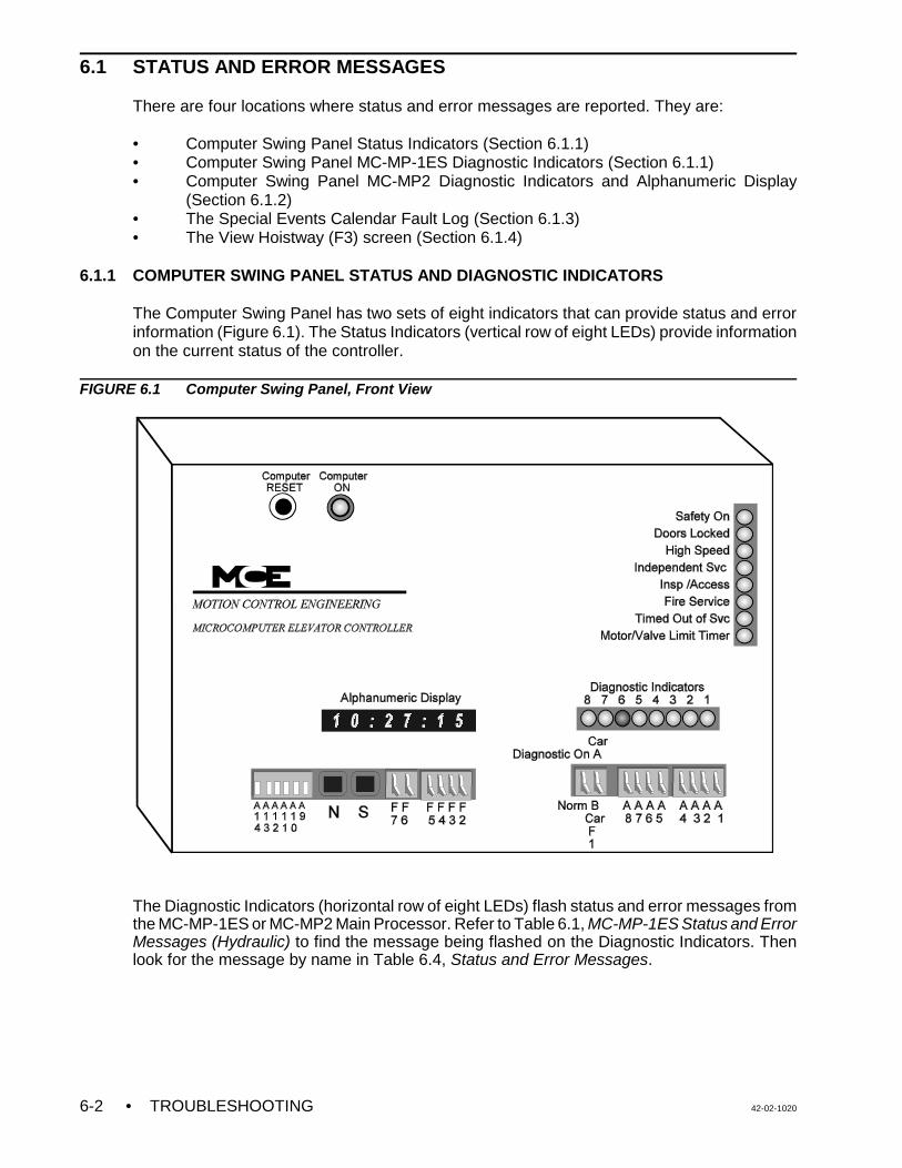
• TROUBLESHOOTING 42-02-10206-2
6.1 STATUS AND ERROR MESSAGES
There are four locations where status and error messages are reported. They are:
• Computer Swing Panel Status Indicators (Section 6.1.1)• Computer Swing Panel MC-MP-1ES Diagnostic Indicators (Section 6.1.1)• Computer Swing Panel MC-MP2 Diagnostic Indicators and Alphanumeric Display
(Section 6.1.2)• The Special Events Calendar Fault Log (Section 6.1.3)• The View Hoistway (F3) screen (Section 6.1.4)
6.1.1 COMPUTER SWING PANEL STATUS AND DIAGNOSTIC INDICATORS
The Computer Swing Panel has two sets of eight indicators that can provide status and errorinformation (Figure 6.1). The Status Indicators (vertical row of eight LEDs) provide informationon the current status of the controller.
FIGURE 6.1 Computer Swing Panel, Front View
The Diagnostic Indicators (horizontal row of eight LEDs) flash status and error messages fromthe MC-MP-1ES or MC-MP2 Main Processor. Refer to Table 6.1, MC-MP-1ES Status and ErrorMessages (Hydraulic) to find the message being flashed on the Diagnostic Indicators. Thenlook for the message by name in Table 6.4, Status and Error Messages.

42-02-1020 TROUBLESHOOTING • 6-3
TABLE 6.1 MC-MP-1ES Status and Error Messages (Hydraulic) � = LED off � = LED blinking
Hex Diagnostic Indicators Status / Error MessageSingle LED scanning Normal Operation - no errors or messages
03 � � � � � � � � Attendant Service Operation
07 � � � � � � � � Hall Call Bus Fuse Blown
09 � � � � � � � � Passcode Requested
0F � � � � � � � � Car Call Bus Fuse Blown
1F � � � � � � � � Timed Out of Service24 � � � � � � � � Car is Overloaded 3C � � � � � � � � Level Down3F � � � � � � � � Door Open and Locked66 � � � � � � � � Check Alphanumeric Display for scrolling message - See Section 6.1.271 � � � � � � � � Test Mode Operation73 � � � � � � � � Pre-test Mode7E � � � � � � � � Security7F � � � � � � � � Independent Service80 � � � � � � � � Inspection81 � � � � � � � � Viscosity Control Function82 � � � � � � � � Door Lock Contact Failure 83 � � � � � � � � Door Open Limit Failure 84 � � � � � � � � Gate Switch Failure 85 � � � � � � � � Gate Switch Relay Redundancy Failure86 � � � � � � � � Door Lock Relay Redundancy Failure 88 � � � � � � � � In-car stop Switch8F � � � � � � � � EarthquakeAA � � � � � � � � Synch FunctionC0 � � � � � � � � Fire Service Phase 2C1 � � � � � � � � Door Lock FailureC2 � � � � � � � � Door Close ProtectionC3 � � � � � � � � Level UpC4 � � � � � � � � Doors Locked but not fully Closed - FrontC5 � � � � � � � � Doors Locked but not fully Closed - RearC9 � � � � � � � � Leveling Sensor Redundancy Failure CA � � � � � � � � Landing System Redundancy FailureCB � � � � � � � � Contactor Proofing Redundancy FailureCF � � � � � � � � Elevator ShutdownDB � � � � � � � � Bottom Floor Demand or Top Floor Demand.E0 � � � � � � � � Fire Service MainE1 � � � � � � � � Emergency PowerE3 � � � � � � � � Car to LobbyE7 � � � � � � � � Heavy LoadE8 � � � � � � � � Light Load E9 � � � � � � � � Aux. Inspection Access FaultEA � � � � � � � � 2nd Landing Aux. Access FaultEB � � � � � � � � Bottom Landing Aux. Access FaultEC � � � � � � � � DPM Redundancy FaultED � � � � � � � � DPMR Redundancy FaultF0 � � � � � � � � Fire Service AlternateF1 � � � � � � � � Hospital ServiceF2 � � � � � � � � Hospital Service Phase 2F3 � � � � � � � � Door Zone Sensor Failure (active state)F4 � � � � � � � � Leveling Sensor Failure (active state)F5 � � � � � � � � Leveling Sensor Failure (inactive state)

TABLE 6.1 MC-MP-1ES Status and Error Messages (Hydraulic) � = LED off � = LED blinking
Hex Diagnostic Indicators Status / Error Message
• TROUBLESHOOTING 42-02-10206-4
NOTE: Refer to Table 6.1, MC-MP Status and Error Messages (Hydraulic) to findthe message being flashed on the Diagnostic Indicators. Then look for themessage by name in Table 6.4, Status and Error Messages.
F7 � � � � � � � � Emergency Power ShutdownF8 � � � � � � � � Valve Limit Timer ElapsedFC � � � � � � � � Motor Limit Timer ElapsedFE � � � � � � � � Both USD and DSD are OpenFF � � � � � � � � Safety Relay Circuit Open
6.1.2 MC-MP2 DIAGNOSTIC INDICATORS AND ALPHANUMERIC DISPLAY
MC-MP2 DIAGNOSTIC INDICATORS - During normal operation these lights scan from rightto left (indicating that the MP2 program is looping properly) or flash ON and OFF to indicate astatus or error condition. If the car is connected to a Group Supervisor in a multi-car groupsystem, the lights will scan from right to left, then left to right, indicating proper communicationbetween the Car Controller and the Group Supervisor.
When a status or error condition exists, the Diagnostic Indicators flash one of severalmessages depending on the software version (MP2 version number scrolls on boot up):
• Software versions 8.02.00 or earlier flash theMC-MP-1ES messages (see Table 6.1).
• Software version 8.03.00 flashes CC Hex.
• Software versions 8.04.00 or later flash 66 Hex.
MC-MP2 ALPHANUMERIC DISPLAY - If the scrolling status or error message is not displayedwhen the Diagnostic Indicators flash, press the N pushbutton until the scrolling messageappears (see Section 5.2.1 ALPHANUMERIC DISPLAY - STATUS AND ERROR MESSAGES).You can lookup the scrolling message in the index and then refer to Table 6.4 Status and ErrorMessages for a description and troubleshooting information, or you can find the scrollingmessage in Table 6.2 MC-MP2 Status and Error Messages Lookup and then find theassociated Message in Table 6.4.

42-02-1020 TROUBLESHOOTING • 6-5
TABLE 6.2 MC-MP2 Scrolling Messages LookupScrolling Message Event Message (see Table 6.4)
2ND LANDING AUX. ACCESS FAULT (non ASME-2000 only) 2nd Landing Aux. Access FaultATTENDANT SERVICE OPERATION Attendant Service OperationAUX. INSPECTION ACCESS FAULT (non ASME-2000 only) Aux. Inspection Access FaultBOTH LEVELING SWITCHES ARE ON (SETUP ERROR), LEARN MODE (IMC only)
Both Leveling Switches are ON (Learn Mode SetupError)
BOTH USD AND DSD INPUTS ARE ACTIVE Both USD and DSD are OpenBOTTOM FLOOR OR TOP FLOOR DEMAND Bottom Floor Demand
Top Floor DemandBOTTOM LANDING AUX. ACCESS FAULT (non ASME-2000 only) Bottom Landing Aux. Access Fault
BRAKE PICK FAILURE (Traction only) Brake Pick FailureCAR CALL BUS IS DISCONNECTED Car Call Bus Fuse BlownCAR IN TEST MODE Test Mode OperationCAR NOT AT BOTTOM LANDING (SETUP ERROR), LEARN MODE (IMC only)
Car not at Bottom Landing (Learn Mode Setup Error)
CAR NOT BELOW DOOR ZONE (SETUP ERROR), LEARN MODE (IMC only)
Car Not Below Door Zone (Learn Mode Setup Error)
CAR NOT ON INSPECTION (SETUP ERROR), LEARN MODE (IMC only) Car Not On Inspection (Learn Mode Setup Error)CAR NOT ON LEVEL DOWN (SETUP ERROR), LEARN MODE (IMC only) Level Down ON (Learn Mode Setup Error)CAR NOT ON LEVEL UP (SETUP ERROR), LEARN MODE (IMC only) Car Not On Level Up (Learn Mode Setup Error)CAR SAFETY DEVICE OPEN Car Safety Device OpenCAR TO LOBBY OPERATION Car To LobbyCONTACTOR PROOFING REDUNDANCY FAILURE Contactor Proofing M
Contactor Proofing Redundancy FailureMX and PT1 Redundancy FailurePT2 & PT3 Redundancy Failure
DIRECTION RELAY REDUNDANCY FAILURE Direction Relay Redundancy FailureDOL AND DLK BOTH ACTIVE Doors Open and LockedDOOR CLOSE FAILURE Door Close ProtectionDOOR LOCK FAILURE Door Lock FailureDOOR LOCK SWITCH FAILURE Door Lock Contact FailureDOOR OPEN LIMIT FAILURE Door Open Limit FailureDOOR ZONE SENSOR FAILURE Door Zone Sensor Failure - On positionDOOR ZONE SENSOR FAILURE - OFF POSITION Door Zone Sensor Failure - Off positionDPM REDUNDANCY FAULT DPM Redundancy FaultDPMR REDUNDANCY FAULT DPMR Redundancy FaultDRIVE FAILED TO RESPOND Drive Failed to RespondDRIVE FAULT 2 (IMC only) Loss of Position Feedback
Parity Sensor Failure (Floor Code)Pattern Door Zone FailurePosition Error at DETSPosition Error at DNTxPosition Error at UETSPosition Error at UNTxRead Sensor Failure (Floor Code)
DRIVE FORCED MOTOR LIMIT TIMER (Traction only) Brake FailureBrake IGBT FailureMLT - Drive ForcedMLT-Drive Forced (ALT)Pattern Detected Overspeed
DRIVE TEMPERATURE SENSOR FAULT (IMC Traction only) Drive Temperature Sensor Fault
EARTHQUAKE OPERATION (Traction only) Earthquake
EARTHQUAKE - REDUCED SPEED OPERATION (Traction only) Earthquake Normal OperationELEVATOR SHUTDOWN SWITCH OR POWER TRANSFER INPUT ACTIVE Elevator Shutdown or Power TransferEMERGENCY POWER OPERATION Emergency PowerEMERGENCY POWER SHUTDOWN Emergency Power ShutdownEMERGENCY STOP INPUT 1 ACTIVATED Emergency Stop Input 1 ActivatedEMERGENCY STOP INPUT 2 ACTIVATED Emergency Stop Input 2 ActivatedENTER SECURITY CODE SecurityEXCESSIVE HEAT IN SMB UNIT (IMC Performa only) Excessive Heat in SMB Unit
EXCESSIVE HEAT IN SYSTEM 12 (IMC-SCR and IMC Performa only) Excessive Heat in System 12FAILURE TO LEAVE THE FLOOR MLT - Failed to Leave Floor

TABLE 6.2 MC-MP2 Scrolling Messages LookupScrolling Message Event Message (see Table 6.4)
• TROUBLESHOOTING 42-02-10206-6
FIRE SERVICE PHASE 1 - ALTERNATE Fire Service AlternateFIRE SERVICE PHASE 1 - MAIN Fire Service MainFIRE SERVICE PHASE 2 Fire Service Phase 2FLT RELAY DROPPED FLT Relay DroppedFRONT DOOR IS LOCKED BUT NOT FULLY CLOSED Doors Locked but not fully Closed - FrontGATE SWITCH FAILURE (non ASME-2000 only) Gate Switch Failure
GOVERNOR SWITCH OPEN (Traction only) Governor Switch OpenHALL CALL BUS IS DISCONNECTED Hall Call Bus Fuse BlownHEAVY LOAD WEIGHER CONDITION Heavy LoadHOISTWAY SAFETY DEVICE OPEN Hoistway Safety Device OpenHOSPITAL PHASE 1 OPERATION Hospital ServiceHOSPITAL PHASE 2 OPERATION Hospital Service Phase 2IMC SUB-SYSTEM NOT READY (IMC only) IMC Sub-System Not ReadyIN CAR STOP SWITCH ACTIVATED In-car Stop SwitchINDEPENDENT SERVICE OPERATION Independent ServiceINSPECTION / LEVELING OVERSPEED FAILURE (IMC Traction only) Inspection/ Leveling OverspeedINSPECTION OPERATION InspectionLANDING SYSTEM REDUNDANCY FAILURE (non ASME-2000 only) Landing System Redundancy FailureLEVELING DOWN Level DownLEVELING SENSOR FAILED - OFF POSITION Leveling Sensor Failure (Inactive State)LEVELING SENSOR FAILED - ON POSITION Leveling Sensor Failure (Active State)LEVELING SENSOR FAILURE Leveling Sensor Redundancy FailureLEVELING UP Level UpLIGHT LOAD WEIGHER CONDITION Light LoadLOSS OF INSPECTION DURING LEARN MODE (IMC only) Loss of IN During Learn (Learn Mode Setup Error)MOTOR LIMIT TIMER (ANTI-STALL) ELAPSED MLT - Excessive PI Correction (Traction)
MLT - Excessive Releveling at Floor- MLT - Timer ExpiredMotor Limit Timer (Traction)Motor Limit Timer (INT) (Traction)Motor Limit Timer (LI) (IMC Traction)Motor Limit Timer (LI & INT) (IMC Traction)External Motor Limit Timer (Hydro)Low Oil Switch (Hydro)
NO RESPONSE FROM PATTERN GENERATOR (SETUP ERROR), LEARNMODE (IMC only)
No Response from Pattern Generator (Learn ModeSetup Error)
NORMAL OPERATIONOVERLOAD CONDITION Car is OverloadedPASSCODE REQUEST Passcode RequestedPG NOT READY (IMC Traction only) Pattern Generator not ReadyPHOTO EYE FAILURE Photo-Eye Failure (Front)
Photo-Eye Failure (Rear)PRESSURE SWITCH ACTIVATED (Hydro only) Pressure Switch ActivatedPRE-TEST MODE Pre-test ModePRIORITY / VIP SERVICE - PHASE 1 Priority/VIP Service Phase 1PRIORITY / VIP SERVICE - PHASE 2 Priority/VIP Service Phase 2REAR DOOR IS LOCKED BUT NOT FULLY CLOSED Doors Locked but not fully Closed - RearREDUNDANCY DOOR LOCK RELAY FAILURE Door Lock Relay Redundancy FailureREDUNDANCY GATE SWITCH FAILURE (non ASME-2000 only) Gate Switch Relay Redundancy FailureSAFETY CIRCUIT IS OPEN Safety Relay Circuit OpenSHUTDOWN OPERATION MG Shutdown Operation/Shutdown SwitchTIME OUT OF SERVICE Timed Out of ServiceVALVE LIMIT TIMER ELAPSED (Hydro only) Valve Limit Timer Elapsed
VISCOSITY CONTROL FUNCTION ACTIVE (Hydro only) Viscosity Control Function3-1-05

42-02-1020 TROUBLESHOOTING • 6-7
DESCRIPTION
Communication LossCommunication Loss [OFF]Sub-System(s) Reset
: N/A: N/A: N/A: N/A: N/A: N/A: 3: 0x03 ( Communication )
12/4/2000, 10:25:30 AM, F4=Main Menu
dnID208c
Special Events Calendar (F7, F7)
ARROWS: Move Cursor, HOME: Oldest, END: Newest, CTRL-T: Troubleshoot
STATUSDirectionHigh SpeedStart FloorStop FloorStep FloorSwitchPIEvent Code
DATE
12/4/2000
TIME
10:05:28 AM10:07:37 AM2:36:18 PM
SPEED (ft/Mmin)CommandTach/EncTerminalSafetyPattern
VOLTAGE (volts)ArmatureMotor FldBrake
SENSOR (volts)Motor FldBrake
CURRENT (amps)ArmatureCommand
POSITION (ft)Absolute
: N/A: N/A: N/A: N/A: N/A
: N/A: N/A: N/A
: N/A: N/A
: N/A: N/A
: N/A
This fault indicates that the car was previously communicating with the GroupSupervisor but is now unable to communicate.
6.1.3 SPECIAL EVENTS CALENDAR FAULT LOG
The Special Events Calendar can document the most recent 250 important fault conditions orevents and display them in chronological order. They can be viewed on the optional CRTterminal connected to either the car controller or the Group Supervisor. The data displayedincludes the type of event or fault, the date and time the fault/event occurred, the date and timethe fault/event was corrected, as well as other information about the status of the elevator whenthe fault or event occurred.
The Special Events Calendar is accessed from the Special Events Calendar Menu. Press theF7 key while the Main Menu is displayed.
View Fault Log (F7, 1 or F7) - From the Special Events Calendar Menu (F7) screen press 1or F7 to display the events logged to the Special Events Calendar (Figure 6.2). This screenmakes it possible to examine the documented faults and events. The latest 14 faults and eventsare displayed in the bottom half of the screen, including the date and time the event occurred.
FIGURE 6.2 Special Events Calendar (F7 - 1) screen
When this screen is first displayed, the most recent event is displayed at the bottom of thescreen. Use the Up / Down Arrow keys to scroll one event at a time, the Page Up / PageDown keys to scroll a page at a time, or the Home / End key to scroll to event 1 or 250.
As each event is selected (reverse video), the description of the event and any other loggeddata is displayed in the top half of the screen. Additional troubleshooting information for eachevent can be displayed by pressing Ctrl + T.

• TROUBLESHOOTING 42-02-10206-8
NOTE: Table 6.4, Status and Error Messages, lists all of the events which canbe recorded in the Special Events Calendar Fault Log, with a descriptionof the event and the recommended troubleshooting actions to be taken.
NOTE: Table 6.4, Status and Error Messages, provides a description of themessages shown in the CAR OPERATION section of the View Hoistway(F3) screen, including recommended troubleshooting actions to betaken. Refer to Table 6.3, View Hoistway (F3) Screen - CAROPERATION to find the desired flag, then look for the fault message byname in Table 6.4.
2/7/2005, 10:25:30 AM, F4= Main Menu
dnAI205c
3
2
1
L
B
3
2
1
L
B> <
CAR OPERATIONFAULT
InspAcc OutServMnFire1 SftyOpn
AOUT
ARROWS/PGUP/PGDN: Select Floor, ENTER KEY: Front Car Call, R: Rear Car Call
Clear Fault Log (F7, 2) - While the Special Event Calendar Menu (F7) screen is displayed, ifthe 2 key is pressed, the message Delete All Events? (Y/N) is displayed. Press Y toclear the Special Events Calendar Fault Log of all events.
6.1.4 VIEW HOISTWAY (F3) SCREEN FAULT FLAGS
The View Hoistway (F3) screen provides information about the status of the controller. Themessages in the CAR OPERATION section of the F3 screen are listed in Table 6.3. and adescription and recommend troubleshooting actions can be found in Table 6.4, Status and ErrorMessages.
FIGURE 6.3 View Hoistway (F3) Screen

42-02-1020 TROUBLESHOOTING • 6-9
TABLE 6.3 View Hoistway (F3) Screen - CAR OPERATION
The flags appear only when the car condition exists. AlmNoDZ Alarm - No Door Zone IndSrv Independent ServiceAlmNoMv Alarm - No Car Movement InServ In ServiceAltFir1 Fire Service Alternate InspAcc InspectionAntiNui Anti-Nuisance Operation MLT MLT - Timer ExpiredAttnSrv Attendant Service Operation MnFire1 Fire Service MainAutoOps Automatic Operation Nudging NudgingBflrDem Bottom Floor Demand OutServ Out of ServiceByp-HLW Hall Call Bypass Operation SftyOpn Car Safety Device OpenEmrgPwr Emergency Power SwngOpr Swing Car OperationEqactv Earthquake TflrDem Top Floor DemandFirePh2 Fire Service Phase 2 TOS Timed Out of ServiceHospEmr Hospital Service
6.1.5 STATUS AND ERROR MESSAGES TABLE
Table 6.4, Status and Error Messages provides a listing of the status and error messages fromthe following:
• Computer Swing Panel MC-MP-1ES Diagnostic Indicator messages• Computer Swing Panel MC-MP2 scrolling messages• Special Events Calendar Fault Log messages• View Hoistway (F3) Screen - CAR OPERATION flag messages
FIGURE 6.4 Legend for Table 6.4, Status and Error Messages
TABLE 6.4 Status and Error MessagesSpecial Event Message SEC F3 Flag MP2 Scrolling Message
2nd Landing Aux. Access Fault 2ND LANDING AUX. ACCESS FAULT
The inputs “Second Landing Access Bypass” (2AB) and “Redundant Second Landing Access Bypass” (R2AB) are compared. The caris shut down and this fault is generated if both inputs have the same status.
Alarm - No Car Movement SEC AlmNoMv
This status indicates that the alarm bell pushbutton was pressed when the car was not moving (ABI).
Alarm - No Door Zone SEC AlmNoDz
This status indicates that the alarm bell pushbutton was pressed when the car was not in door zone (ABIZ).

TABLE 6.4 Status and Error MessagesSpecial Event Message SEC F3 Flag MP2 Scrolling Message
• TROUBLESHOOTING 42-02-10206-10
Anti-Nuisance Operation AntiNui
This status indicates that the load weigher is detecting a minimal load in the car; therefore anti-nuisance logic is in effect allowing onlya few car calls to be registered.
Attendant Service Operation AttnSrv ATTENDANT SERVICE OPERATION
This status indicates that the attendant service input (ATS) is activated. Attendant service is maintained as long as the ATS input isactivated, and there are no “emergency service” (e.g., fire service) demands. • Check the status of the ATS input. When the car is in Attendant Service operation the input should be high.
Automatic Operation AutoOps
This status indicates that the car is running on Automatic Operation.
Aux. Inspection Access Fault AUX. INSPECTION ACCESS FAULT
The inputs “Inspection Access” (INA) and “Redundant Inspection Access” (RINA) are compared. The car is shut down and this fault isgenerated if both inputs have the sam.e status.
Both USD and DSD Are Open SEC BOTH USD AND DSD INPUTS ARE ACTIVE
This fault indicates that the Up Slow Limit Switch (USD input) and Down Slow Limit Switch (DSD input) are simultaneously open. Thisusually indicates a problem with one of the terminal landing limit switches. The MP detects this condition when USD=0, DSD=0,DLK=1.• Inspect both limit switches and associated wiring. • Measure voltages at relay board terminals 11 (USD) and 13 (DSD). Reference the job prints and verify measured voltages against
the status of the limit switches. • If voltages are appropriate, possible causes may be a defective:
1. 147Kohm resistors on top of the main relay board, HC-RB4-x (for USD/DSD inputs).2. C2 ribbon cable between HC-RB4-x and HC-PI/O boards.3. Input circuit on the HC-PI/O board.
Bottom Floor Demand SEC BflrDem BOTTOM FLOOR OR TOP FLOOR DEMAND
This status is generated either when the established PI value corresponds to the top terminal landing, but the Up Slow Limit Switch isclosed or when a valid PI value can not be found. A Bottom Floor Demand is generated to move the car away from the landing andestablish a car position. Possible causes are: • The COMPUTER RESET button was pressed.• Initial Power-up.• The state of the limit switch contacts do not correspond to the current PI value (example: the car is in door zone and the PI value
corresponds to the bottom terminal landing, but the Down Slow Limit Switch is closed).• The car was placed on Inspection (the computer does not attempt to maintain the PI value while the car is being moved in a
“manual” fashion; Bottom Floor Demand is declared when the car is placed back into automatic operation).Troubleshooting:• If the floor encoding is invalid, the car should move to one of the terminal landings to establish car position. • If the floor encoding is valid and the car is level at a landing, check the floor encoding magnets or vanes (perhaps a valid code
cannot be read). • If the floor encoding is invalid, check the terminal limit switches and associated wiring. • Verify that the input circuits for USD and DSD are not failing by checking for defective:
1. 47Kohm resistors on top of the main relay board, HC-RB4-x. 2. C2 ribbon cable between HC-RB4-x and HC-PI/O boards.3. HC-PI/O board.4. Short circuit on HC-RB4-x board..
Bottom Landing Aux. Access Fault SEC BOTTOM LANDING AUX. ACCESS FAULT
The inputs “Bottom Landing Access Bypass” (BAB) and “Redundant Bottom Landing Access Bypass” (RBAB) are compared. The caris shut down and this fault is generated if both inputs have the same status.
Car Call Bus Fuse Blown SEC CAR CALL BUS IS DISCONNECTED
This fault indicates that there is no power to the car call circuits on the HC-CI/O board(s). A problem may exist with the Car Call Busfuse (F2CC) or the car call common wiring (bus 2CC).• Check the Car Call Bus fuse (F4) in the controller. • Check the wires that go to the Car Call Power inputs (labeled PS1/PS2/PS3) on the HC-CI/O board(s) in the controller. • Check for the proper installation of the call board “jumper plug” on the HC-CI/O board(s). Look at the notch on the chip and match it
up according to the notch orientation label on the HC-CI/O board.

TABLE 6.4 Status and Error MessagesSpecial Event Message SEC F3 Flag MP2 Scrolling Message
42-02-1020 TROUBLESHOOTING • 6-11
Car is Overloaded OVERLOAD CONDITION
This status indicates that the Overload input (OLW) is activated, or the perceived load in the car has exceeded the threshold value setfor an overload condition.• For a discrete OLW input: check the status of the OLW input (wired to a load weigher contact), and determine if the status of the
input is appropriate relative to the load in the car.• For an analog load weigher: check the perceived load percentage using the on-board diagnostic station. Determine if the value
displayed (percentage) is appropriate relative to the load in the car.
Car Out of Service with Doors Locked SEC
This fault indicates that the car was shut down because it was delayed from leaving the landing for a predetermined time (default 5minutes) after it timed out of service. The doors were locked when the timer elapsed. • Correct the problem that caused the car to time out of service. Refer to the Special Event Calendar for the event name, then
troubleshoot that event.
Car Out of Service without Doors Locked SEC
This fault indicates that the car was shut down because it was delayed from leaving the landing for a predetermined time (default 5minutes) after it timed out of service. Doors were not locked when the timer elapsed. • Suspect an obstruction that has kept the doors from closing, thus preventing the car from leaving.• Verify that controller terminal #48, on the HC-RBH board, for zero voltage.• Correct the problem that caused the car to time out of service. Refer to the Special Event Calendar for the event name, then
troubleshoot that event.
Car Safety Device Open SEC SftyOpn CAR SAFETY DEVICE OPEN
This fault indicates that one or more of the car safety circuit devices is open (e.g., emergency exit contact, safety clamp switch, car-topemergency stop switch). This error is generated when the safety string input (SAF) is low, and the safety circuit has been opened“upstream” of the SAFC input.• Check the applicable car safety devices. Refer to controller wiring prints for applicable devices.
Car to Lobby CAR TO LOBBY OPERATION
This status indicates that the Car To Lobby input (CTL) has been activated.• Check the status of the CTL input. It should be high.
Communication Loss SEC
This fault indicates that the car was previously communicating with the Group Supervisor but is now unable to communicate.• Verify that the RS-422 communication cable is not removed from the car’s MC-RS board.• Verify the jumpers on all of the controllers’ MC-RS boards.• Check for a defective MC-RS board on any of the controllers.
Contactor Proofing Redundancy Failure SEC CONTACTOR PROOFING REDUNDANCY FAILURE
This fault indicates that one (or more) of the main power contactors has not dropped out properly after the car stopped moving. Thecomputer generates this error when either the CNPB or CNPM input remains low after the car has stopped.• Verify that the CNP input is high when the car is not in motion.• Consult the job prints for the specific job.
Door Close Protection SEC DOOR CLOSE FAILURE
This fault indicates that the doors were unable to close in typically 60 seconds. • Check door lock contacts for proper closure and conductivity.• Check individual doors and door tracks for physical obstructions. • Verify that the Door Close Limit contact functions properly. • Check for a faulty Door Lock Sensor input (DLS) or Door Close Limit input (DCL).
Door Lock Contact Failure SEC DOOR LOCK SWITCH FAILURE
This fault indicates that a door lock contact appears to have failed in the closed state. The computer compares the state of the landingDoor Lock Sensor input (DLS or DLSR) with the state of the Door Close Limit input (DCL). If DLS or DLSR remains high after thedoors have opened (DCL=1), this failure will be declared. (It appears that the door lock contact is shunted or has remained closed).• Measure the voltage on the DLS or DLSR input, with doors open. • If voltage exists on DLS or DLSR while the doors are open, trace the source of the voltage.• If no voltage exists on the DLS or DLSR, suspect faulty DLS or DLSR input circuit. Check the HC-IOX and HC-I4O boards.
Door Lock Failure SEC DOOR LOCK FAILURE
This fault indicates that the doors have closed, DCL = 0 (or DCLC = 1 if retiring cam), a demand exists for the car to move (DCP = 1),but the doors did not lock (DLK = 0) within 80 seconds with the door close power output (DCP) turned on.• If no Retiring Cam is used, verify that the door lock contacts are closed to provide power to the door lock input (DLK = 1).• If the Retiring Cam option is set:
1. Verify that the Retiring Cam relay is activated (DCP = 1, DPM = 1 or DCLC = 1) and the doors are locked (DLK = 1).2. Momentarily place the car on Inspection to reset the Door Lock Failure. 3. Verify the proper operation of the Retiring Cam circuitry and mechanism.

TABLE 6.4 Status and Error MessagesSpecial Event Message SEC F3 Flag MP2 Scrolling Message
• TROUBLESHOOTING 42-02-10206-12
Door Lock Relay Redundancy Failure SEC REDUNDANCY DOOR LOCK RELAY FAILURE
This fault indicates that one of the door lock relays has failed to drop out.• Verify that, with the hoistway doors open, there is no power on the Door Lock Sensor Relay input (RDLS or RDLSR, if the car has
rear doors). • If the RDLS or RDLSR input is high and the doors are open, then a door lock relay has failed to drop.• Verify that the door lock relay(s) operates properly. • If no voltage appears on the RDLS (or RDLSR) input, suspect a faulty RDLS (or RDLSR) input circuit. Replace the HC-IOX and/or
HC-I4O boards.
Door Open Limit Failure SEC DOOR OPEN LIMIT FAILURE
This fault indicates that a door open limit contact appears to have failed in the open state. This means that the Door Open Limit input(DOL or DOLR) is low--indicating an open door--while the Gate Switch (GS) or Door Lock Sensor (DLS) inputs are high--indicating aclosed and locked door.• Verify that, with the doors closed, there is power on the Door Open Limit input (DOL or DOLR). DOL or DOLR must be high when
DLS and/or GS is high.• Check the wire, in the controller, to terminal #36 on HC-RB4-x to verify DOL.• If there is a rear door, check terminal #36 on the rear door board to verify DOL.
Door Open Protection SEC
This fault indicates that the doors were unable to open in typically 12 seconds.• Check door lock contacts for proper closure and conductivity.• Check individual doors and door tracks for physical obstructions.• Verify that the door Open Limit contact functions properly.
Doors Locked but not fully Closed - Front FRONT DOOR IS LOCKED BUT NOT FULLY CLOSED
This fault indicates that the Door Lock input (DLK) was high (doors locked ) and the Door Closed Limit input (DCL) was high (doors notfully closed). DCL should be low when doors are locked.• Determine the state of the doors.• If the doors are closed, check the voltage on the DCL input terminal. If the voltage is high, adjust the Door Closed Limit switch so
the switch opens prior to DLK.• Check for a faulty door close limit contact or associated wiring.
Doors Locked but not fully Closed - Rear REAR DOOR IS LOCKED BUT NOT FULLY CLOSED
This fault indicates the Door Lock input (DLK) was high (doors locked) and Door Closed Limit Rear input (DCLR) was high (doors notfully closed). DCLR must be low when doors are locked.• Determine the state of the doors.• If the doors are closed, check the voltage on the DCLR input terminal. If the voltage is high, adjust Rear Door Closed Limit switch so
the switch opens prior to DLK.• Check for a faulty door close limit contact or associated wiring.
Doors Open And Locked SEC DOL AND DLK BOTH ACTIVE
This fault indicates that the Door Open Limit input (DOL) was low while the Door Lock input (DLK) was high. The leveling inputs (LUand LD) must also be low to log this fault.• Determine the state of the doors. • If the doors are open, check the voltage on terminal #8 (DLK), on the HC-RBH board. • If voltage exists, determine source of voltage (there should be no voltage on terminal 8 if doors are open and car is not leveling). • If the doors are closed, check the voltage on terminal #36 (DOL), on the HC-RBH board. The voltage should be high. • If voltage does not exist, check for faulty door open limit contact (contact should be closed if doors are not fully open) or associated
wiring. • If voltages are appropriate, suspect faulty input circuit (either DLK or DOL input circuit). Check the 47Kohm resistors on the
HC-RBH and HC-PI/O boards.
Door Zone Sensor Failure (active state) DOOR ZONE SENSOR FAILURE
This fault indicates that the Door Zone input (DZ) did not deactivate during the run. Probable causes are: shorted door zone sensor orassociated circuitry (within the landing system assembly); faulty wiring from the landing system to the controller; or a faulty computerinput circuit (main relay board or HC-PI/O board). • Check the operation of the door zone sensors and associated wiring (place the car on inspection, move the car away from the floor,
noting the transitions in the door zone signal(s) coming from the landing system). • Verify that the computer diagnostic display of DZ (or DZ rear) matches the state of the sensor signals at the main relay board (or
rear door relay board).
DPM Redundancy Fault DPM REDUNDANCY FAULT
A failure of a front door input, relay or associated circuitry has been detected. This logic detects failure of the input structure andhardware associated with the DPM (door position monitor) input. • Valid when SAF = 1. When DLK is ON (1) then input DPM must also be ON (1). When DOL = 0, DPM = 0. If this is not the case,
then a DPM redundancy fault is recorded and the car is prevented from operating

TABLE 6.4 Status and Error MessagesSpecial Event Message SEC F3 Flag MP2 Scrolling Message
42-02-1020 TROUBLESHOOTING • 6-13
DPMR Redundancy Fault DPMR REDUNDANCY FAULT
A failure of a rear door input, relay or associated circuitry has been detected. This logic detects failure of the input structure andhardware associated with the DPMR (door position monitor rear) input.• Valid when SAF = 1. When DLK is ON (1), input DPMR must also be ON (1). When DOLR = 0, DPMR = 0. If not, a DPMR
redundancy fault is recorded and the car is prevented from operating.
Earthquake SEC Eqactv EARTHQUAKE OPERATION
This fault indicates that one or both of the earthquake inputs (EQI, CWI) is high. The appropriate code-mandated earthquakeoperation is applied, for ANSI and California Earthquake Operation the car is brought to a floor and then shut down.• The elevator may be returned to normal service by means of momentary reset button on the earthquake board (HC-EQ2). This
should be done by authorized personnel, after it has been determined that it is safe to do so. • Should the system remain in this mode of operation after the reset button has been pressed, check the status of the earthquake
sensing devices (seismic switch or counterweight derailment device).
Elevator Shutdown or Power Transfer ELEVATOR SHUTDOWN SWITCH OR POWER TRANSFER INPUT ACTIVE
This status indicates that either the Elevator Shutdown input (ESS) has been activated or the Power Transfer input (PTI) has beenactivated. The car is stopped at the next available floor and then shut down.• Verify that the status of the computer inputs (ESS and PTI) are appropriate relative to the status of the switch or contact that feeds
the input.
Emergency Power SEC EmrgPwr EMERGENCY POWER OPERATION
This event indicates that the system is on Emergency Power operation. The Emergency Power input (EPI) is low, which indicates thatthe system is being powered by an emergency-power generator.• If system is not running on an emergency-power generator, check the voltage on the EPI terminal (this terminal is generally found in
the group supervisor controller in multi-group applications). • If voltage does not exist on EPI, check contact and associated wires that feed the EPI input. • If voltage does exist on the EPI terminal, suspect faulty EPI input circuitry (HC-IOX or HC-I4O board). [Note: In some applications,
the EPI input resides in the individual elevator controller. Refer to specific job prints for details.]• If this is a group system with emergency power, and the Group Supervisor has yet to be installed, place a jumper from the 2 bus to
the EPI input on each local car’s HC-IOX board. Remove the jumper when the Group Supervisor is installed.
Emergency Power Shutdown SEC EMERGENCY POWER SHUTDOWN
This status indicates that the car is shutdown during Emergency Power Operation when the controller is unable to communicate withthe Group Supervisor. When the Group Supervisor is unable to coordinate running the elevators on Emergency Power, this shutdownoccurs in order to prevent the cars from running all at the same time and possibly overloading the generator.
Emergency Stop Input 1 Activated EMERGENCY STOP INPUT 1 ACTIVATED
This message is displayed when the Emergency Stop Input 1 (ESTP1) goes high.
Emergency Stop Input 2 Activated EMERGENCY STOP INPUT 2 ACTIVATED
This message is displayed when the Emergency Stop Input 2 (ESTP2) goes high.
External Motor Limit Timer SEC MOTOR LIMIT TIMER (ANTI-STALL) ELAPSED
This fault indicates that the EXMLT input is active. This is an MLT shutdown wtih an External Motor Limit Timer (EXMLT).
Fire Service Alternate SEC AltFir1 FIRE SERVICE PHASE 1 - ALTERNATE
This event indicates that the system is on Fire Recall Operation (Fire Service Phase I), using the alternate fire recall floor. This recallis generally initiated by the activation of a smoke detector at the main fire recall floor. In some applications, an alternate fire recallswitch may be specified (FRAON input). • Inspect the fire sensors (especially the main floor sensor) and the Fire Phase I switch wiring. For some fire codes including ANSI,
the Fire Phase I switch must be turned to the BYPASS position and then back to OFF to clear the fire service status, if activated bya smoke sensor.
• If this is a group installation and the group has yet to be installed, make sure the 2-bus is jumpered to terminal #38 on the HC-RBHboard. Remove the jumper when Fire Service wiring is complete.
Fire Service Main SEC MnFire1 FIRE SERVICE PHASE 1 - MAIN
This event indicates that the system is on Fire Recall Operation (Fire Service Phase I), using the main fire recall floor. This recall isgenerally initiated by the activation of a smoke detector at a landing other than the main fire recall floor. Fire recall operation to themain floor can also be initiated by the activation of the fire recall switch (input FRON or FRON2).• Inspect the fire sensors and the Fire Phase I switch wiring. For some fire codes including ANSI, the Fire Phase I switch must be
turned to the BYPASS position and then back to OFF to clear the fire service status if activated by a smoke sensor.• If this is a group installation and the group has yet to be installed, make sure the 2-bus is jumpered to terminal #38 on HC-RBH.• If this installation must comply with the requirements of the 1998 Addendum to the ASME A17.1-1996 or later code, and the
machine room and hoistway sensors have not yet been installed, or if this is a group system and the Group Supervisor has yet to beinstalled, make sure the FRMR and FRHTW inputs on the HC-IOX boards in each simplex or local car controller are jumpered to the2/2F bus, as applicable.

TABLE 6.4 Status and Error MessagesSpecial Event Message SEC F3 Flag MP2 Scrolling Message
• TROUBLESHOOTING 42-02-10206-14
Fire Service Phase 2 SEC FirePh2 FIRE SERVICE PHASE 2
This event indicates that the car is on In-car Fireman’s Service (Fire Phase 2). The in-car fire service switch has been placed in the on(FCS) or hold (HLD) position.• Inspect the phase 2 switch and wiring. In most fire jurisdictions, the car must be returned to the fire floor at which Fire Phase 2 was
activated, the doors must be fully open, and the phase 2 switch must be turned OFF to remove the elevator from Fire Phase 2operation.
FLT Relay Dropped FLT RELAY DROPPED
The FLT relay is dropped as a result of one or more of many possible fault conditions.• Check the Event Calendar to determine what has caused the FLT Relay Dropped message. Then look up that message or
messages in this table to determine the appropriate troubleshooting and/or corrective action.
Gate Switch Failure SEC GATE SWITCH FAILURE
This fault indicates that a car gate contact failed to open when the car doors opened. The computer checks the gate switch contactinput (GS or GSR) against the door close limit input (DCL). If the gate switch contact remains closed (GS=1 or GSR=1) while the dooris open (DCL=1) the fault is logged. Such a state would indicate that the gate switch contact has been shunted, or a contact orassociated wiring is faulty. • Verify that, with the doors open, there is no power on the GS input (GS must be low when DCL is high). • If no voltage exists on the GS input, suspect a faulty GS input circuit (HC-IOX or HC-I4O board). • If there is a rear door perform the same tests for the GSR input.
Gate Switch Relay Redundancy Failure SEC REDUNDANCY GATE SWITCH FAILURE
This fault indicates that a car gate switch relay failed to release when the doors opened.• Verify that, with the car gate open, there is no power on the RGS input (or RGSR, if rear doors). • If the RGS input is high, suspect a stuck or welded gate switch relay.• Verify that the gate switch relay(s) operates properly. • If no voltage appears on the RGS (or RGSR) input, suspect a faulty RGS (or RGSR) input circuit.
Governor Switch Open SEC SftyOpn GOVERNOR SWITCH OPEN
This fault indicates that the governor switch is open. This error is generated when the safety string input (SAF) is low, and the safetycircuit has been opened “upstream” of the GOV input.• Check the governor overspeed switch.
Hall Call Bus Fuse Blown SEC HALL CALL BUS IS DISCONNECTED
This fault indicates that there is no power to the hall call circuits on the HC-CI/O board(s). A problem may exist with the Hall Call Busfuse or the hall call common wiring.• Check the Hall Call Bus fuse in the controller. • Check the wires that go to the Hall Call Power inputs on the HC-CI/O board(s) in the controller. • Check for proper installation of the call board “jumper plug” on the HC-CI/O board(s).
Hall Call Bypass Operation Byp-HLW
This status indicates that the load weigher is detecting a significant load in the car so hall calls will be bypassed.
Heavy Load HEAVY LOAD WEIGHER CONDITION
This status indicates that the Heavy Load (HLI) input has been high.• For a discrete HLI input (wired to a load weigher contact): Check the status of the HLI input, and determine if the status of the input
is appropriate relative to the load in the car. • For an analog load weigher: Check the perceived load percentage using the on-board diagnostic station. Determine if the value
displayed (percentage) is appropriate relative to the load in the car.
Hoistway Safety Device Open SEC SftyOpn HOISTWAY SAFETY DEVICE OPEN
This fault indicates that one or more of the Hoistway Safety Circuit Devices is open (e.g., pit stop switch, car and cwt buffers switches,up/down final limit switches). This error is generated when the safety string input (SAF) is low, and the safety circuit has been opened“upstream” of the SAFH input.• Check the applicable items (e.g., pit stop switch, car and cwt buffers switches, up/down final limit switches). Refer to the specific
controller wiring prints for applicable devices.
Hospital Service SEC HospEmr HOSPITAL PHASE 1 OPERATION
This status indicates that the car was placed on Hospital Service. • Hospital Service can be initiated by the registration of a hospital call, or by the activation of the in-car Hospital Service switch
(HOSP input).• Verify that the status of the in-car hospital switch computer input (HOSP) is appropriate relative to the status of the key-switch.

TABLE 6.4 Status and Error MessagesSpecial Event Message SEC F3 Flag MP2 Scrolling Message
42-02-1020 TROUBLESHOOTING • 6-15
Hospital Service Phase 2 SEC HospEmr HOSPITAL PHASE 2 OPERATION
This status indicates that the car has answered a hospital emergency call or the in car hospital emergency key switch has beenactivated (HOSP2 is high).• The car has been placed on in-car Hospital Emergency Service. The car will remain in this mode until the in-car Hospital Service
key-switch is turned off. • Verify that the status of the in-car hospital switch computer input (HOSP2) is appropriate relative to the status of the key-switch.
In-car Stop Switch SEC SftyOpn IN CAR STOP SWITCH ACTIVATED
This fault indicates that the in-car stop switch has opened the safety circuit.• Check the status of the in-car emergency stop switch and associated wiring.
Inconspicuous Riser SEC
This event indicates that the System is on Swing operation or the Inconspicuous Riser is functional.• Check Swing Car Operation.• Inspect the SWG switch on the controller.
Independent Service SEC IndSrv INDEPENDENT SERVICE OPERATION
This event indicates that the Independent Service switch has been turned on, or the TEST/NORMAL switch on the Relay board is inthe TEST position.• Check the Independent Service switch. • Inspect the TEST/NORMAL switch on the Relay board on the controller.• Check the wiring to the relay board (HC-RBH) terminal #49.
Inspection SEC InspAcc INSPECTION OPERATION
This event indicates that the hoistway access, car top inspection or relay panel inspection switch is on INSP or the hoistway and/orcar-door bypass switch is on bypass. The Inspection input (IN) is low.• Check all of the inspection switches and associated wiring.• Check the wiring to the relay board (HC-RBH) terminal #59
Landing System Redundancy Failure SEC LANDING SYSTEM REDUNDANCY FAILURE
This fault indicates that one of the landing system sensors or associated relays has malfunctioned. A Landing System RedundancyFailure will be declared if the LSR input remains high throughout a run.• Verify proper operation of the Door Zone (DZ), Level Up (LU) and Level Down (LD) relays while the car is moving in the hoistway.• The LSR signal must go low at least once during a run.
Level Down LEVELING DOWN
This status is normally on when the car is just above a floor. If the car is level with the floor and this message appears, it is usually theresult of a switch or sensor problem.• Inspect the LD switch or sensor on the landing system and the placement of the landing system vane or magnet for that floor.
Level Up LEVELING UP
This status is normally on when the car is just below a floor. If the car is level with the floor and this message appears, it is usually theresult of a switch or sensor problem.• Inspect the LU switch or sensor on the landing system and the placement of the landing system vane or magnet for that floor.
Leveling Sensor Failure (Active State) LEVELING SENSOR FAILED - ON POSITION
This fault indicates that the MP detected a LU or LD input that is stuck in the active state. Computer input circuit (main relay board orHC-PI/O board).• Verify that the computer diagnostic display (F3 screen or ADDR 29H, bits 3 and 7) of LU and LD matches the state of the sensor
signals at the main relay board (terminals 25X and 26X). • Check also the operation of any contacts that may be placed at the “low side” (the “1-bus” side) of the LU and LD relay coils (e.g.,
H, INT). Check that such contacts close properly when appropriate.
Leveling Sensor Failure (Inactive State) LEVELING SENSOR FAILED - OFF POSITION
This fault indicates that the MP detected a LU or LD input that is stuck in the inactive state. Troubleshooting tips:• Move above and below a landing, noting the transitions in the leveling signal(s) coming from the landing system. • Verify that the computer diagnostic display of LU and LD matches the state of the sensor signals at the main relay board.

TABLE 6.4 Status and Error MessagesSpecial Event Message SEC F3 Flag MP2 Scrolling Message
• TROUBLESHOOTING 42-02-10206-16
Leveling Sensor Redundancy Failure SEC LEVELING SENSOR FAILURE
This fault indicates that one of the LU or LD sensors appears to have failed. The MP computer has observed one of the following faults:• One of the leveling inputs was active continuously throughout a floor-to-floor run• The appropriate leveling input was not seen prior to the arrival of the car at a door zoneTroubleshooting Tips:• Verify the proper operation of the leveling sensor signals when moving the car in the hoistway. • Check for a LU or LD input circuit failure by looking for defective:
1. 47kohm resistor on top of the main relay board, HC-RBH.2. C2 ribbon cable.3. HC-PI/O board input circuit.4. Inputs at terminals 25 and 26 on the HC-RBH board.
Light Load LIGHT LOAD WEIGHER CONDITION
This status indicates that the Light Load Weighing (LLI) input is activated. The Light Load error message is generated whenever theload inside the car is less than the threshold specified to activate Anti-Nuisance operation, and car calls are registered.• Response is only required if the anti-nuisance function (cancellation of car calls) appears to activate even when the car is loaded to
a value above the threshold load value. • For a discrete (LLI) input (wired to a load weigher contact): check the status of the (LLI) input and determine if the status is
appropriate relative to the load in the car. • For an Analog Load Weigher: check the perceived load percentage using the on-board diagnostic station. Determine if the
percentage displayed is appropriate relative to the load in the car.
Lost Door Lock During Run SEC
This fault indicates that the Door Lock input was lost while the car was traveling through the hoistway. • Check door lock adjustment to prevent clipping of door lock mechanism when car passes a floor. • If logged with another fault, this event may be a side effect of the other fault.
Low Oil Switch SEC MOTOR LIMIT TIMER (ANTI-STALL) ELAPSED
This fault indicates that the Low Oil Switch (LOS) input is active. This MLT shutdown gets latched until the car is momentarily onInspection or reset.
Motor Limit Timer SEC MLT MOTOR LIMIT TIMER (ANTI-STALL) ELAPSED
The motor limit timer has elapsed before the car completed its movement (car going up).
Nudging Nudging
This status indicates that the door nudging operation has commenced. Doors will be closed with reduced speed and torque as requiredby code.
Out of Service OutServ
This status indicates that the car is not available for normal passenger service.
Passcode Requested SEC PASSCODE REQUEST
This status indicates that the Passcode Request option has been activated and that a passcode is required in order to run the car onany mode other than Inspection. Refer to the instructions titled Setting the Passcode in Section 5.
Photo-Eye Failure SEC
This fault indicates that the one of the photo-eye inputs has been active for a considerable amount of time.• Check for abnormal blockage of the optical device.• Check for a failure of the device itself, or of the photo-eye input (PHE or PHER) circuit.• Ensure that the safety edge has power.
Photo-Eye Failure (Front) SEC PHOTO EYE FAILURE
This fault indicates that the front-door, photo-eye input (PHE) was activated during a run.• Check for abnormal blockage of the optical device.• Check for a failure of the device itself, or of the photo-eye input (PHE) circuit.• Ensure that the safety edge has power.
Photo-Eye Failure (Rear) SEC PHOTO EYE FAILURE
This fault indicates that the rear-door, photo-eye input (PHER) was activated during a run.• Check for abnormal blockage of the optical device.• Check for a failure of the device itself, or of the photo-eye input (PHER) circuit.• Ensure that the safety edge has power.

TABLE 6.4 Status and Error MessagesSpecial Event Message SEC F3 Flag MP2 Scrolling Message
42-02-1020 TROUBLESHOOTING • 6-17
Power Down SEC
This event indicates that the entire controller lost power or was manually reset. This event is logged when the MC-CGP-4 board losespower or is reset while running.
Pressure Switch Activated PRESSURE SWITCH ACTIVATED
This message is displayed when the Pressure Switch Input (PSS) is programmed and activated (low).• Check the associated hardware device and take appropriate action.
Pre-test Mode PRE-TEST MODE
This status indicates that the car is bypassing hall calls and disabling the gongs. However, car calls may still be entered and will beanswered. Once the last car call is answered, the car will park with doors closed. This function is normally used to capture a car.
Priority/VIP Service Phase 1 PRIORITY / VIP SERVICE - PHASE 1
This status indicates that a Priority/VIP Service momentary call switch was activated at any floor.• The car has been assigned a Priority/VIP Service call. The car can be removed from Priority/VIP Service by toggling (On-Off) the
in-car Priority/VIP Service key-switch. The car should automatically return to normal service after a pre-determined period of time(typically 60 seconds) if the in-car switch is not activated.
Priority/VIP Service Phase 2 PRIORITY / VIP SERVICE - PHASE 2
This status indicates that the car has answered a Priority/VIP call or the in car Priority/VIP Service key switch has been activated(PRIS is high).
Releveling SEC
This event indicates that the car has traveled through the Dead Zone on an approach to the floor, and has had to relevel. • Widen the dead zone (LU/LD)
Safety Relay Circuit Open SEC SftyOpn SAFETY CIRCUIT IS OPEN
This fault indicates that a contact in the safety relay circuit is open. This message is generated when the safety string input (SAF) islow and all safety devices through the in-car stop switch are closed (STOP=1). This indicates that a device “below” terminal #20 hasopened.• Refer to the job prints to determine all components that make up the safety relay circuit (between terminal 20 and the CSAF output
device). • Check each of these devices to determine the cause of the fault.
Security SEC ENTER SECURITY CODE
This event indicates that the secured car call button has been pressed, and the controller is awaiting proper security code to beentered through the car call buttons. A 10-second period of time is allowed to enter the correct code.• Enter floor pass code with car call buttons on COP.• See Section 5.3.2 for instructions on how to program or change security codes.
Sub-System Reset - Operation Processor SEC
This event indicates that the MP processor was reset.
Sub-System(s) Reset SEC
This event indicates that the CGP did not see every processor in the system power up.
Swing Car Operation SwngOpr
This status indicates that the car is operating as a swing car, independently from the Group Supervisor. This car should be servicing ariser of hall calls dedicated to that car.
Synch Function SYNCHRONIZATION OPERATION
This event indicates that the SYNCI input has been momentarily activated and the car will be taken to the buffer in order to equalizethe hydraulic pressure in systems that use more than one piston to move the car. The down normal limit switch is bypassed (byactivation of a relay connected to the SYNC output) and the car is moved at slow speed in the down direction. The down slow valvecircuits are energized for 30 seconds to ensure that the car has been lowered all the way to the buffer. Once this timer elapses, the caris moved back up to the bottom landing.
System Power Up/Reset SEC
This event indicates that the Communication processor detected that all the individual system processors successfully powered up. Ifone or more processors fail to successfully power up, then this event will be replaced by one or more Sub-System Reset eventsdetailing which individual processors successfully powered up.
Test Mode Operation CAR IN TEST MODE
This status indicates that the TEST/NORM switch on the HC-RB4-SCRI board is in the TEST position.• Check the TEST/NORM switch on the HC-RB4-SCRI board.

TABLE 6.4 Status and Error MessagesSpecial Event Message SEC F3 Flag MP2 Scrolling Message
• TROUBLESHOOTING 42-02-10206-18
Timed Out of Service SEC TOS TIME OUT OF SERVICE
This fault indicates that the car delayed reaching its destination (direction arrow established - SUA/SDA). In most cases, the car isdelayed at a floor because the doors are prevented from closing. When the timed out of service (TOS) status is generated, the car isremoved from hall call service until it is allowed to leave the landing.• The timer is used to take the car out of service when the car is held excessively. Typically this occurs when the doors are held open
by continuous activation of the photo-eye, a call button, or another reopening device. The TOS timer is a field-adjustable timer,which can be lengthened or shortened to suit the specific installation (via the MP diagnostics).
Timed Photo-Eye Failure SEC
The photo-eye was on longer than the predetermined time (default 60 seconds).• Check for an abnormal blockage of the optical device.• Check for a failure of the device itself, or of the photo-eye input (PHE or PHER) circuit.
Top Floor Demand SEC TflrDem BOTTOM FLOOR OR TOP FLOOR DEMAND
This status is generated either when the established PI value corresponds to the bottom terminal landing, but the Down Slow LimitSwitch is closed or when a valid PI value can not be found. A top-floor demand is generated to move the car away from the landing toestablish car position. Possible causes are:• The COMPUTER RESET button was pressed.• Initial Power-up.• The state of the limit switch contacts do not correspond to the current PI value (example: the car is in door zone and the PI value
corresponds to the bottom terminal landing, but the Dn Slow Limit Switch is closed).• The car was placed on Inspection (the computer does not attempt to maintain the PI value while the car is being moved in a
“manual” fashion ( Top Floor Demand is declared when the car is placed back into automatic operation).Troubleshooting tips: • If no floor encoding exists, car should move to one of the terminal landings to establish car position. • If floor encoding system exists and car is level at a landing, check the floor encoding magnets or vanes (perhaps a valid code
cannot be read). • If floor encoding does not exist, check the terminal limit switches and associated wiring. • Verify the input circuits for USD and DSD by looking at:
• 47Kohm resistors on top of the HC-RBH.• C2 ribbon cable on top of the HC-RBH.• HC-PI/O board.• Short circuit on relay board.
Valve Limit Timer Elapsed MOTOR LIMIT TIMER (ANTI-STALL) ELAPSED
The Valve Limit Timer starts whenever the controller attempts to move the car in the down direction. The timer is reset when the carreaches its destination floor. This message is generated if the timer expires before the car reaches its destination, and the controllerwill stop trying to move the car in order to protect the valves. Verify that the Down Sense Input (DNS) is high when the car moves in the down direction. Inspect the valves, valve solenoids and associated wiring.
Viscosity Control Function SEC VISCOSITY CONTROL FUNCTION ACTIVE
This message indicates that the VCI input is activated and the car is executing the Viscosity Control Function. The car is moved to thebottom landing and the computer periodically runs the motor (not the valves) to warm the oil in the system. The pump is turned ON forthree minutes, OFF for nine minutes, ON for three minutes, etc. until the VCI input is deactivated. Registration of any call will preemptthe Viscosity Control Function, as will any special operation, e.g., fire service, independent service, etc. Check the device that is wired to the VCI input (usually an oil temperature sensor.

42-02-1020 TROUBLESHOOTING • 6-19
12/10/2002, 10:25:30 AM, F4=Main Menu
dnID209c
Special Events Calendar Menu (F7)
F7 or 1 -
2 -
3 -
8 -
View Fault Log
Clear Fault Log
Configure by Type
Print Events
6.2 USING THE SPECIAL EVENTS CALENDAR
The Special Events Calendar documents the 250 most recent fault conditions or events anddisplays them in chronological order. They can be viewed on the optional CRT terminalconnected to either the car controller or the Group Supervisor. The data displayed includes thetype of event or fault, the date and time the fault/event occurred, the date and time thefault/event was corrected, as well as other information about the status of the elevator whenthe fault or event occurred.
The Special Events Calendar Fault Log is accessed from the Special Events Calendar Menu(Figure 6.5). Press the F7 key while the Main Menu is displayed.
VIEW FAULT LOG
From the Special Events Calendar Menu (F7) screen press 1 or F7 to display the events loggedto the Special Events Calendar (Figure 6.6). This screen makes it possible to examine thedocumented faults and events. The latest 14 faults and events are displayed in the bottom halfof the screen, including the date and time the event occurred.
FIGURE 6.5 Special Events Calendar Menu (F7) screen
When this screen is first displayed, the most recent event is displayed at the bottom of thescreen. Use the Up / Down Arrow keys to scroll one event at a time, the Page Up / PageDown keys to scroll a page at a time, or the Home / End key to scroll to event 1 or 250. Aseach event is selected (reverse video), the description of the event and any other logged datais displayed in the top half of the screen. Additional troubleshooting information for each eventcan be displayed by pressing Crtl + T (see Figure 6.7). Table 6.4, Status and Error Messageslists the faults or events which are recorded, including a description and recommendedtroubleshooting actions.

• TROUBLESHOOTING 42-02-10206-20
2/16/2000, 10:25:30 AM, F4= Main Menu
dnID248b
Special Events Calendar Troubleshooting Tips
12/4/2000, 10:05:28 AM, Communication Loss
--Verify that the RS-422 communication cable is not removed from the Car'sMC-RS board.--Verify the jumpers on all of the controllers' MC-RS boards.--Check for a defective MC-RS board on any of the controllers.
ESC or CTRL-T: Special Events Calendar
DESCRIPTION
Communication LossCommunication Loss [OFF]Sub-System(s) Reset
: N/A: N/A: N/A: N/A: N/A: N/A: 3: 0x03 ( Communication )
12/4/2000, 10:25:30 AM, F4=Main Menu
dnID208c
Special Events Calendar (F7, F7)
ARROWS: Move Cursor, HOME: Oldest, END: Newest, CTRL-T: Troubleshoot
STATUSDirectionHigh SpeedStart FloorStop FloorStep FloorSwitchPIEvent Code
DATE
12/4/2000
TIME
10:05:28 AM10:07:37 AM2:36:18 PM
SPEED (ft/Mmin)CommandTach/EncTerminalSafetyPattern
VOLTAGE (volts)ArmatureMotor FldBrake
SENSOR (volts)Motor FldBrake
CURRENT (amps)ArmatureCommand
POSITION (ft)Absolute
: N/A: N/A: N/A: N/A: N/A
: N/A: N/A: N/A
: N/A: N/A
: N/A: N/A
: N/A
This fault indicates that the car was previously communicating with the GroupSupervisor but is now unable to communicate.
FIGURE 6.6 Special Events Calendar (F7 - 1) screen
FIGURE 6.7 Special Events Calendar Troubleshooting (F7 - 1 - Crtl +T) screen

42-02-1020 TROUBLESHOOTING • 6-21
XXXXXXXXXXXXXXXXXXXX
CommunicationCommunicationCommunicationCommunicationCommunicationCommunicationCommunicationOperationCommunicationCommunicationCommunicationCommunicationCommunicationCommunicationCommunicationOperationCommunicationCommunicationOperationOperation
Alarm - No Car MovementAlarm - No Door ZoneBoth USD and DSD Are OpenBottom Floor DemandCar Call Bus Fuse BlownCar Out of Service with Doors LockedCar Out of Service without Doors LockedCar Safefy Device OpenCommunication LossContactor Proofing Redundancy FailureDirection Relay Redundancy FailureDoor Close ProtectionDoor Lock Contact FailureDoor Open Limit FailureDoors Open and LockedEarthquakeFire Service Phase 2Gate Switch Relay Redundancy FailureGovernor Switch OpenHoistway Safety Devide Open
12/5/2000, 10:25:30, F4= Main Menu
dnID239d
Special Events - Configure by Type (F7, 3)
The Log column controls which events are logged to the Special Events Calendar. Place an X in the Log column to have events of the type specified bythis row to be logged to the Special Events Calendar. Events with a "." in theLog column will not be logged.
Log Process Event Description 1 of 39
ARROWS: Select, ENTER KEY: Edit, S: Saves
CLEAR FAULT LOG
While in the Special Event Calendar Menu (F7) screen is displayed, if the 2 key is pressed, themessage Delete All Events? (Y/N) is displayed. Press Y to clear the Special EventsCalendar of all events.
SPECIAL EVENTS - CONFIGURE BY TYPE
In order to aid in troubleshooting, the list of events which are logged to the Special EventsCalendar can be configured based on the event type.
While in the Special Event Calendar Menu (F7) screen is displayed, press the 3 key to accessthe Special Events - Configure by Type (F7, 3) screen (see Figure 6.8). The Log columncontrols which events are logged to the Special Events Calendar Fault Log. Place an 'X' in thiscolumn if you want the event type listed in the selected row to be logged to the Special EventsCalendar. When the Event Description is highlighted, a description of the event type isdisplayed above the column headings (see Figure 6.9). Table 6.4, Status and Error Messagesprovides a complete listing of events. The event messages that are logged to the Special EventCalendar are shown with SEC in the Location column.
FIGURE 6.8 Special Events - Configure by Type (F7, 3) screen
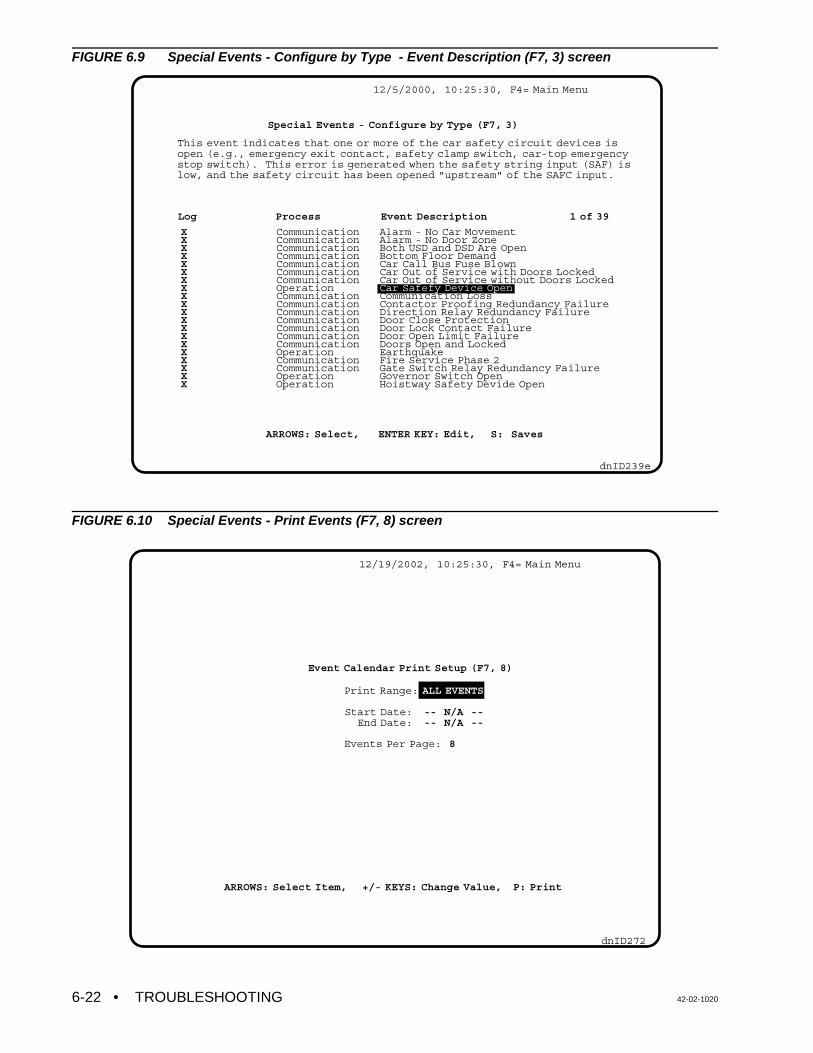
• TROUBLESHOOTING 42-02-10206-22
XXXXXXXXXXXXXXXXXXXX
CommunicationCommunicationCommunicationCommunicationCommunicationCommunicationCommunicationOperationCommunicationCommunicationCommunicationCommunicationCommunicationCommunicationCommunicationOperationCommunicationCommunicationOperationOperation
Alarm - No Car MovementAlarm - No Door ZoneBoth USD and DSD Are OpenBottom Floor DemandCar Call Bus Fuse BlownCar Out of Service with Doors LockedCar Out of Service without Doors LockedCar Safefy Device OpenCommunication LossContactor Proofing Redundancy FailureDirection Relay Redundancy FailureDoor Close ProtectionDoor Lock Contact FailureDoor Open Limit FailureDoors Open and LockedEarthquakeFire Service Phase 2Gate Switch Relay Redundancy FailureGovernor Switch OpenHoistway Safety Devide Open
12/5/2000, 10:25:30, F4= Main Menu
dnID239e
Special Events - Configure by Type (F7, 3)
This event indicates that one or more of the car safety circuit devices isopen (e.g., emergency exit contact, safety clamp switch, car-top emergency stop switch). This error is generated when the safety string input (SAF) islow, and the safety circuit has been opened "upstream" of the SAFC input.
Log Process Event Description 1 of 39
ARROWS: Select, ENTER KEY: Edit, S: Saves
12/19/2002, 10:25:30, F4= Main Menu
dnID272
Print Range: ALL EVENTS
Start Date: -- N/A -- End Date: -- N/A --
Events Per Page: 8
Event Calendar Print Setup (F7, 8)
ARROWS: Select Item, +/- KEYS: Change Value, P: Print
FIGURE 6.9 Special Events - Configure by Type - Event Description (F7, 3) screen
FIGURE 6.10 Special Events - Print Events (F7, 8) screen

42-02-1020 TROUBLESHOOTING • 6-23
Controller Online Success Rate
12/6/2000, 10:25:30, F4= Main Menu
dnID233a
Car A 100%YES
Network Status (F11, 1)
dnID227c
Diagnostics Menu (F11)
1 -
3 -
4 -
5 -
7 -
8 -
Network Status
Memory Dump
Task Info for CGP
Resource Usage
MP Input/Output
Car Performance
9/18/2002, 10:25:30 AM, F4=Main Menu
6.3 USING THE DIAGNOSTICS
System diagnostics are available using the optional CRT terminal with Release 4Communication software. Diagnostics are accessed via the Diagnostics Menu (F11) screen.
FIGURE 6.11 Diagnostics Menu (F11) screen
FIGURE 6.12 Network Status (F11, 1) screen

• TROUBLESHOOTING 42-02-10206-24
dnID265
MP Diagnostic Input/Output Flags
20
21
22
23
24
25
26
27
28
29
2A
2B
2C
2D
2E
2F
DOLM
DCF
INT
LFP
LLW
DNDO
DMD
TOS
SD
HLD
PHE
DC
DCP
FRA
UFP
DLK
LD
DCB
MLT
STC
SDA
DZ
UC
DOF
HSEL
FCS
HLW
EQI
UCB
PSTX
SAF
DSD
EQA
DOL
CC
LOT
CSB
FRS
HLI
IND
DZORDZ
DDP
CCB
MGR
HCR
BFD
ATSF
DBC
DCC
DNS
IN
UPDO
DMU
H
HCDX
FRM
SU
SE
HTC
NUDG
UPS
LU
DCA
REL
CCD
SUA
ECRN
GEU
DHO
CCT
STD
FWI
DEL
PK
UCA
DSH
ISV
USD
CD
GED
DOI
SDT
DSHT
STU
YSIM
LLI
UDP
CCA
RUN
ISRT
FRC
TFD
EPR
7/19/2000, 10:25:30 AM, F4=Main Menu
Network Status - The status of communication between the car controller and the GroupSupervisor can be verified using the Network Status (F11, 1) screen. A Success Rate of lessthan 100% indicates possible improper termination of the High-Speed Serial CommunicationLink. Proper termination is achieved by installing or removing shunts on jumpers JP1 and JP2on the MC-RS Communication Interface boards at the ends of the communication chain whileobserving the Success Rate percentage for each local Car. The goal is to achieve 100%Success Rate for each car, or the highest percentage possible. This diagnostic screen is alsoavailable on the M3 Group Supervisor (see Section 3.9.2 Using the Network Status DiagnosticsScreen in the M3 Group Supervisor manual, part #42-02-G004)
Memory Dump - (screen not shown) This diagnostic screen shows the status of memorylocations within the controller's computers. MCE Technical Support personnel may requestinformation from this screen while troubleshooting a problem.
Task Info for CGP - (screen not shown) This diagnostic screen shows the status of varioustasks performed by the MC-CGP-4(8) Communication Processor Board. MCE TechnicalSupport personnel may request information from this screen while troubleshooting a problem.
Resource Usage - (screen not shown) This diagnostic screen shows resource usage in theMC-CGP-4 Communication Processor Board. MCE Technical Support personnel may requestinformation from this screen while troubleshooting a problem.
MP Input / Output - Displays the status of the MP inputs and outputs (Figure 6.13).
FIGURE 6.13 MP2 Input/Output (F11,7) screen

42-02-1020 TROUBLESHOOTING • 6-25
9/18/2002, 10:25:30 AM, F4=Main Menu
ESC: Exit P: Print Screen C: Clear Data H: Help I/D: Edit
dnID270
DoorsClosing
DoorsClosed
CarStarts
CarStops
Car Speed : N/AFloor Height : N/A
Programmed FloorsStart Floor End Floor
Current Car Info.Position Direction Door Status
DoorsOpening
DoorsOpen
#: 2A#: 3A
: 3A: IN: OPEN
DoorsClosing
DoorsClosing
DoorsClosing
SET (HCT) 4.0
SET (SDT) 1.0
AVG
AVG
AVG
SET (CCT) 2.0
<--- 1.4 --->
<---- 1.5 ---->
<---- 1.5 ---->
<-- 1.0 -->
<---------- 2.0 ---------->
<---------- 2.0 ---------->
<--------------------- 4.5 --------------------->
<------------------- 4.0 ------------------->
<---------------------------- 5.5 ----------------------------->
<---------------------------- 6.5 --------------------------------------------->
<---------------------------- 8.5 --------------------------------------------------------------->
Doors 3/4 Open
Performance Time
DoorClse&Start Run Time
Short Door Time
Car Call Time
Hall Call Time
Cycle Time(with Passenger Transfer)
Car Call Cycle Time(without Passenger Transfer)
Hall Call Cycle Time(without Passenger Transfer)
Car Performance Graph (TIME in seconds)
dnID271
Car Performance Report (F11, 8)
Up/DN Arrow: Select +/-: Change Value C KEY: Clear PKEY: Print Screen
Start FloorEnd Floor
#: 2A#: 3A
Car SpeedFloor Height
Car @ Flr: 3ACar Dir.: OUTDar Door: OPEN
: N/A: N/A
1.4
1.5
2.0
1.5
4.5
5.0
1 5.5
2 6.5
4 8.5
Door Close Time (DCT):Doors Start Closing - TO- Doors Closed
Door Close & Car Start Time (DT):Doors start Closing -TO- Car Stops
Run Time (RT):Car Starts -TO-Doors Open
Door Open Time (DOT):Doors Start Opening -TO- Doors Open
Performance Time (PT):DT + RT + (1/2 * DOT)
Cycle Time (CT):Doors Start Closing -TO- Doors Open
Average Short Door Dwell Time (SDT): 1Cycle Time (with Passenger Transfer):CT + SDT
Average Car Call Dwell Time (CCT): 2Car Call Cycle Time (wighout Passenger Transfer):CT + CCT
Average Hall Call Dwell Time (HCT): 4Hall Call Cycle Time (without Passenger Transfer):CT + HCT
9/18/2000, 10:25:30 AM, REC, F4=Main Menu
FIGURE 6.14 Car Performance Graph (F11, 8) screen
FIGURE 6.15 Car Performance Report (F11, 8, H) screen

• TROUBLESHOOTING 42-02-10206-26
Car Performance - The Car Performance Graph (F11, 8) screen and the Car PerformanceReport (F11, 8, H) screen provide car performance data including:
• Door Close Time (DCT)• Door Close & Car Start Time (DT)• Run Time (RT)• Door Open Time (DOT)• Performance Time (PT)• Cycle Time (CT)• Average Short Door Dwell Time (SDT)• Average Car Call Dwell Time (CCT)• Average Hall Call Dwell Time (HCT)
6.4 TROUBLESHOOTING CAR OPERATION CONTROL (COC)
Usually, a malfunction is due to a faulty input or output signal. Inputs are signals generatedoutside the controller cabinet that connect to terminals inside the cabinet, and are subsequentlyread by the computer during its input scan. Outputs are signals generated by the computer thatenergize relays or turn on indicators during the computer's normal output scan. Since anincorrect input or output can cause a system malfunction, tracing these signals to find thesource of the problem is essential. Read the example problem under Tracing Signals in theController to become familiar with signals generated in the system.
6.4.1 DOOR LOGIC
As complex as it is, the door logic basically answers one simple question; should the doors beopen? The computer looks at certain inputs and then calls upon specific logic to answer thisquestion. All of the inputs and flags generated by the specific logic are available for viewingthrough the EOD. When troubleshooting a door problem, inspecting the action and sequenceof these flags and inputs is important. The status of these logic flags will generally point towardthe root of the problem. Once the computer has determined the answer to the door statusquestion, the appropriate outputs are turned ON or OFF, so the doors are in the desired state.
The computer looks at the following inputs:• DBC - Door Close Button input• DCLC - Door Closed Contacts input (Retiring Cam only)• DLK - Door Locks input• SE - Safety Edge input• DOL - Door Open Limit input• DZ - Door Zone input• PHE - Photo Eye input
The computer generates the following outputs:• DCF - Door Close Function output• DCP - Door Close Power output• DOF - Door Open Function output• NUDG - Nudging output
TRACING SIGNALS IN THE CONTROLLER
The following example shows how an input signal can be traced from its source (field wire) toits destination inside the computer (EOD). Monitor the Door Zone (DZ) flag. The DZ flag canbe monitored using the Computer Swing Panel Diagnostic Indicators as described in Section

42-02-1020 TROUBLESHOOTING • 6-27
NOTE: If this installation has rear doors and at least one floor where bothopenings exist, look up the rear door zone flag (DZR). To do so, theDiagnostic On/Norm switch and the A5 switch must be up. All otherswitches are down. Diagnostic Indicator 6 shows the status of DZR.
5.4.1, Viewing the MC-MP Computer Variable Flags. Moving the car in the hoistway shouldcause this flag to turn ON and OFF whenever the car goes through a floor. If the flag (LED)does not turn ON and OFF, the following could be causing the problem.
1. Defective Door Zone sensor.2. Incorrect hoistway wiring. 3. Faulty termination of hoistway wiring to the (DZ) terminal inside the controller.4. Defect on the HC-RBH or HC-PI/O board.
First, determine whether the problem is inside or outside the controller. With a voltmeter, probethe Door Zone terminal (27). This terminal is in Area 3 of the job prints. Moving the car in thehoistway should cause the voltmeter to read 120VAC when the car is in the door zone. If whenthe car passes through the door zone the voltmeter does not read 120VAC the problem isexternal to the controller (see items 1, 2, and 3 above). If the voltmeter does read 120VACwhen the car passes through the door zone the problem is internal to the controller (see item4 above). The job prints show the DZ signal goes to the right hand side of the DZ relay to a 47K1W resistor, to pin 8 of connector C2 on the HC-RBH Relay board, and then to pin 8 ofconnector C2 on the HC-PI/O board.
Figures 6.17 and 6.18 show the HC-PI/O and HC-RBH boards and the location of the DZ signalin the controller. Notice that if terminal 27 is powered, approximately 120VAC will be presentat the bottom of the 47K 1W resistor corresponding to DZ. The top of the same resistor shouldread about 5VAC with respect to COM.
The HC-RBH board has test pads on the front of the board which surround every relay andconnector. Relays IN2 and SAF each have a legend that indicates which pad corresponds towhich contact or its coil on this board. To be sure that the input from terminal 27 is making itsway to the relay coil, probe the test pad on the lower right hand side of the DZ relay.
It is not necessary to remove the relay or get to the back of the HC-RBH board to trace signalson the board. Signals can be traced on the HC-PI/O board. If the signal gets to the HC-PI/Oboard but does not get to the computer, it is safe to assume that the problem is on the HC-PI/Oboard.
Important computer-generated logic flags:• CCT - Car Call Time flag • DOI - Door Open Intent flag • DSH - Door Shortening (Intermediate) flag • DSHT - Door Shortening (Final) flag • HCT - Hall Call Time flag • LOT - Lobby Time flag • SDT - Short Door Time flag
Using the logic flags listed above, the computer makes a decision regarding the doors. TheDoor Open Intent flag's (DOI) status reflects the computer's decision. If the computerrecognizes the necessity of either opening the doors or keeping the doors open, this flag willcome ON. This flag can be found using the EOD. When viewing this flag, the correspondingDiagnostic Indicator will turn ON when the computer decides that the doors should be open.

• TROUBLESHOOTING 42-02-10206-28
H Picked
Car Call Active
Call cancelled at point of slow down
CC--CCTHC--HCTLC--LOT
PHE/SE--SDT
Car DeceleratesAt floorCCT * DZ * H --DOI
DOI = DOF = ON
DOF = DO = OFF--CCT Starts
CCT = OFF = DOI
DEMAND?
DONE
DOI = OFF -- DCF = ON
DCF = ON = DC
CD = HD = DLK = ON DCL = OFF
DCF = OFF
DCP = ON
DONE
CC = Car CallCCT = Car Call TimeCD = Car Door LockDC = Door Close RelayDCF = Door Close FunctionDCL = Door Close LimitDCP = Door Close PowerDLK = Door LockDO = Door Open RelayDOF = Door Open FunctionDOI = Door Open IntentDOL = Door Open LimitDPM = Door Position MonitorDZ = Door ZoneH = High SpeedH = High Speed DroppedHC = Hall CallHCT = Hall Call TimeHD = Hall Door LocksLC = Lobby CallLOT = Lobby Time(door dwell time)PHE = Photo EyeSE = Safety EdgeSDT = Short Door Time
NOTE: -- (hyphen) = Results In, For example if a car call is set (CC) then at the point of slowdown this results in the setting of the CCT dwell time.
CD = HD = DPM = ON, DCL = OFF
CD = HD = OFFDO = ON
DPM = OFF,DCL = ON
DOORS FULLY OPEN -- DOL = OFF
** Note that DPM must make prior to establishing door lock (CD or HD).
Door Sequence of Operation
DPM = ON **
Yes
* = logical AND
DONE
NoDOL = ON
FIGURE 6.16 Door Sequence of Operation Flowchart

42-02-1020 TROUBLESHOOTING • 6-29
The DOI flag is a useful flag to inspect when troubleshooting door problems. Remember if DOIis ON, it will turn the DOF output ON which should pick the DO relay. The door should stayopen until the DOL (Door Open Limit) turns OFF. The absence of DOL will turn the DOF outputOFF. DOI will remain ON for the door dwell time (CCT, HCT, etc.). When DOI turns OFF, theDCF output turns ON and the DC relay will close the car doors. The signal that turns the DCFoutput OFF is DLK (Doors Locked) or possibly DCLC if the car has a retiring cam. After thedoors are locked there is approximately a two-second delay before the DCF output turns OFF.
If there is a demand for the car (as is evidenced by the DMU or DMD flags being on) and if theDOI flag is not ON, then the DCP (Door Close Power) output will be turned ON regardless ofthe position of the door. The DCP output is used to provide door closing power while the carruns through the hoistway for those door operators requiring it, such as those made by theG.A.L. corporation.
If the doors get stuck because the door interlock keeper failed to lift high enough to clear thedoor interlock during the opening cycle, then the doors cannot complete opening, which coulddamage the door motor. The Door Open Protection Timer will eventually stop trying to open thedoors and the car will then go on to the next call. Similarly, if the doors do not close all the way,the computer recycles the doors at a programmed interval in an attempt to clear the problem.
The computer basically looks for a reason to open the doors. If a valid reason to open the doorsis not found, or if conditions are detected that prohibit the opening of the doors, the logic willclose the doors (reset, or turn DOI OFF). To open the doors, the car must be in a door zoneand not running at high or intermediate speed. Once the car has settled into a proper positionto open the doors, a condition must exist that indicates that the doors should be open. Someof these conditions are listed below:
• Call demand at the current landing (or a call has just been canceled)• Safety Edge/Door Open Button (DOB) input• Emergency/Independent Service conditions • Photo Eye input
When a call is canceled, one of the following door time flags should be turned ON: CCT, HCT,or LOT. When one of the reopening devices (SE or DOB) is active, the SDT flag is turned ON.When an Emergency or Independent Service condition exists, the presence of the particularcondition will cause the DOI flag to be set. Some of these conditions include: Fire Service,Emergency Power operation, Independent Service, Attendant Service, etc.
Once the state of the computer flags has been determined, inspect the high voltage hardwareto see if the appropriate functions are being carried out. For example, if the doors are closedand the DOI flag is set, the doors should be opening (the DO relay picked). If the doors areopen and the DOI flag is cleared (turned OFF), the doors should be closing (the DC relaypicked).
It is vital to determine whether or not the control system is doing what its logic determines itshould be doing. If the control system is doing what the logic intended it to do, then it isimportant to determine how the logic came to its conclusions. If the control system is not doingwhat the logic intended it to do, then it is important to determine what is preventing the desiredfunction from being carried out. The diagnostics on the Computer Swing Panel and/or the CRTcan help determine which situation is present. The output flags will show which outputs thecomputer is attempting to turn ON/OFF. Compare the flags with what is actually happening inthe high voltage hardware.

• TROUBLESHOOTING 42-02-10206-30
SAF -Safety String InputDBC - Door Button Close InputSE/DOB - Safety Edge/ PHE - Photo Eye InputDOL - Door Open Limit InputSTU - Step Up InputSTD - Step Down Input
DZ - Door Zone InputIN - Inspection Or Access InputIND - Independent Service InputUPS - Up Direction Sense InputDNS - Down Direction Sense InputLU - Level Up InputLD - Level Down InputUSD - Up Slow Down Input
DSD - Down Slow Down InputDLK - Door Lock InputFRS - Fire Phase I InputFCS - Fire Phase II InputFRA - Alternate Fire Phase I InputSPARE 1SPARE 2
Voltages for car at floor #1With Power OFF Check for Ground
For above inputs ON = 5VDC OFF = 0VDC
FIGURE 6.17 HC-PI/O Power Input/Output Board Quick Reference
42-QR-HC-PCI/O Rev. 1 HC-PI/O QUICK REFERENCE CARD (Board 3)
Connector C2
INPUT PIN
SAFDBCSE/DOBPHEDOLSTUSTDDZININDUPSDNSLULDUSDDSDDLKFRSFCSFRASPARE 1SPARE 2
12345678910111213141516171819202122
Connector C1
OUTPUT PIN
SST/MGRFWISPARE 2 input SPARE 1 inputNUDGLamp CommonCSAFSUB/RELDCPDCFStop SW OutDOFUPDODNDOStop SW SourceH
12,4356789,11101213,1514161817,1920

42-02-1020 TROUBLESHOOTING • 6-31
FIGURE 6.18 HC-RBH Relay Board Details

• TROUBLESHOOTING 42-02-10206-32
6.4.2 CALL LOGIC - NORMAL OPERATION
Calls are input to the system by grounding the appropriate call input, as labeled on the CallInput/Output board (Figure 6.19, HC-CI/O Call Input/Output Board Quick Reference). The actof physically grounding the call input terminal turns on the corresponding LED on the Callboard. Recognition and acceptance of the call by the computer will cause the indicator toremain lit on the board. Cancellation of the call turns the indicator off. The single input/outputterminal on the Call board accepts call inputs from the call fixture pushbuttons, and also servesas the output terminal illuminating the call fixtures to indicate registration of a call. This meansthat the field wiring is identical to that used for a standard relay controller.
The computer may intentionally block call registration. When the computer prevents car callregistration, it turns ON the Car Call Disconnect flag (CCD) for that car. Inspection of this flagin the diagnostics (ADDR 2C, Diagnostic Indicator #3) will tell if the computer is preventing theacceptance of calls. If the CCD flag is ON, the reason for this condition must be discovered.CCD condition is caused by: Fire Service, motor limit timer elapsed, bottom or top floordemand, etc.
A corresponding flag exists for hall call registration prevention. The computer may detectconditions that prevent hall calls from registering, and set the Hall Call Disconnect Flag(HCDX). This is a system flag (as opposed to a per car flag) but is available for viewing in thediagnostic display along with each car's operating flags. There are many reasons for thecomputer to reject hall call registration: Fire service, a hall call bus problem, no available carsin service to respond to hall calls, etc.
If a call circuit becomes damaged or simply stuck on as the result of a stuck push-button, theelevator will release itself from the stuck call automatically. If the pushbutton remains stuck, thecar will stop at the floor each time it passes. Again, the computer will release itselfautomatically, thereby allowing continued service in the building.

42-02-1020 TROUBLESHOOTING • 6-33
Call Power Terminals Bottom most Call Terminal*
Call Label Strip*If a call board is replaced, removethe Call Label Stripand transfer it tothe new board
Jumper PlugIf a call board isreplaced, the jumperplug must betransferred to thenew board and thenotch orientationmust stay the same
Bottom mostResistor Fuse*
Bottom mostTriac*Watch out forpolarity whenreplacing
* The Triacs,Resistor Fusesand Call Terminalsare layed out in thesame sequence asshown on the CallLabel.
FIGURE 6.19 HC-CI/O Call Input/Output Board Quick Reference
42-QR-HC-CI/O Rev. 2 HC-CI/O QUICK REFERENCE CARD Board 2

• TROUBLESHOOTING 42-02-10206-34
NOTE: Call terminal voltage must be $ 85% of call supply voltage.Example: If supply is 100VAC, terminal voltage may be 85VAC to
100VAC. 80VAC is insufficient.
6.4.3 TROUBLESHOOTING THE CALL CIRCUITS
If there is a problem with a call, first disconnect the field wire or wires from that call terminal todetermine if the problem is on the board or in the hoistway wiring or fixtures. Disconnect thecalls by unplugging the terminals, or removing individual wires. If the individual field wire isdisconnected, lightly tighten the screw terminal since it may not make contact if an attempt ismade to ground the terminal using a jumper when the screw on the terminal is loose.
TABLE 6.5 Call Board Troubleshooting
Problem Recommended steps to resolve the problem
Call Terminal Voltageis insufficient
1. Turn OFF the power and remove the resistor fuse associated with thatterminal.
2. Turn ON the power and check terminal voltage again.3. If no voltage is present on the terminal:
a. Check the jumper plug (header) on the HC-CI/O Call board. Thejumper plug socket is located on the right hand side near the callindicators. If a Call board is replaced, this jumper plug must betransferred to the new board and stay in the same board position(more than one Call board on the controller).
b. Verify that the correct incoming power is on terminals marked PS1,PS2 and PS3. NOTE: Power will exist on at least one and possiblymore of these terminals.
Call LED is ON eventhough the field wire isremoved
1. Reset the computer (Computer Reset pushbutton on Swing Panel). 2. Run the car to the nearest landing to reset PI. 3. It may be necessary to reset the computer in the Group Supervisor in order
to reset a latched hall call.4. If the call does not cancel under these conditions--replace the call board
Cannot register a hallcall at the call board
To discover whether the problem is with the call board or the field wiring: 1. First remove the resistor fuse and disconnect the field wire(s). 2. Verify that the HCDD, Hall Call Disconnect Computer Variable Flag is OFF
(Address 2C, LED 6).3. Verify that there is proper voltage on the call terminal. 4. Register a call by shorting the call terminal to terminal 1 or GND and verify
with EOD as described in Section 5.4.3, Viewing and Entering Calls (thecall registered light on the call board may not work correctly).
5. If the call does not register under these conditions--replace the call board.6. If the call circuit works with field wires removed, before connecting wires,
jumper the wire(s) to ground or terminal 1 and press the call pushbutton. Ifa fuse blows, there is a field wiring problem. If connecting the call wirescauses a problem, the call board may be damaged.
Call remains latchedeven though the cararrives at that landing
Remove the associated resistor fuse. If call cancels, replace the bad resistorfuse.

42-02-1020 TROUBLESHOOTING • 6-35
NOTE: Before troubleshooting the call indicators, ensure that the call circuit isworking correctly, the field wires are connected and the resistor fuses areplugged in. If the board is arranged for neon (or LED) indicators(HC-CI/O-N), the board indicators are not affected by the fixture bulbs.
6.4.4 TROUBLESHOOTING THE CALL INDICATORS
When working correctly, a call indicator glows brightly when a call is registered and glows dimlyor not at all when a call is not registered.
TABLE 6.6 Call Indicator Troubleshooting
Problem Recommended steps to resolve the problem
With a call registered, the CallIndicator is dimly lit (Call Board isHC-CI/O)
Incandescent bulb in the fixture for the call is burned out or missing.Replace the bulb.
Indicator glows bright whether ornot there is a call registered
Bad triac or triac driver transistor. Check triac with power OFF andfield wire removed. Failed triac usually measures a short circuit fromthe metal back (collector) to terminal 1. If board is not in system,measure short between metal back and pad area around mountinghole. Be careful, the metal back of the triac is connected to AC whenpower is ON. NOTE: bottom triac corresponds to bottom terminal.
6.5 PC BOARD QUICK REFERENCES
This section contains a quick reference for the PC boards found in the typical HMC-1000-HScontroller. They are as follows:
• MC-MP-1ES Main Processor Board Quick Reference . . . . . . . . . . . . . . . . Figure 6.20• MC-MP2 Main Processor Board Quick Reference . . . . . . . . . . . . . . . . Figure 6.21• HC-PI/O Power Input/Output Board Quick Reference . Figure 6.17 in Section 6.4.1• HC-CI/O Call Input/Output Board Quick Reference . . . Figure 6.19 in Section 6.4.2• MC-CGP-4 Communication Processor Board Quick Reference . . . . . . . Figure 6.22• MC-RS Communication Interface Board Quick Reference . . . . . . . . Figure 6.23• HC-IPLS IP Landing System Board Quick Reference . . . . . . . . . . . . . Figure 6.24• Standard Board Layout . . . . . . . . . . . . . . . . . . . . . . . . . . . . . . . . . . . . . . . . Figure 6.25

• TROUBLESHOOTING 42-02-10206-36
FIGURE 6.20 MC-MP-1ES Main Processor Board Quick Reference
42-QR-MC-MP-IES Rev. 1 MC-MP-1ES QUICK REFERENCE
JUMPER TYPICAL SETTING DESCRIPTION
J3 AA = 27C512 or 27C256 EPROMB = 27C128 EPROM
J4 AA = 27C512 EPROMB = 27C256 or 27C128 EPROM
J5 see DescriptionN/C = Car ControllerON = M3 Group Supervisor
J6 N/C Jumper not loaded
J7 AA = 32K X 8 RAM, M5M525610-LP or HY62256ALP-10B = 8K X 8 RAM, TC5564 or AM99C88
J8 AA = 32K X 8 RAM, M5M525610-LP or HY62256ALP-10B = 8K X 8 RAM, TC5564 or AM99C88

42-02-1020 TROUBLESHOOTING • 6-37
FIGURE 6.21 MC-MP2 Main Processor Board Quick Reference
42-02-MC-MP2 Rev. 1 MC-MP2 QUICK REFERENCE
JUMPER TYPICAL SETTING DESCRIPTION
JP5 see DescriptionN/C = Car ControllerA pins 1 & 2 = M3 Group Supervisor
JP6 N/C Jumper not loaded
JP9 AA = 27C020, 27C2001, 27C040 or 27C4001 EPROMB = 27C512, 27C010 or C27C1001EPROM
JP10 N/C Jumper not loaded
JP11 A A = SRAM A16 Bank select enabled, B = Bank select disabled
JP12 A A = ROM A17 Bank select enabled, B = Bank select disabled
JP13 A A = ROM A16 Bank select enabled, B = Bank select disabled

• TROUBLESHOOTING 42-02-10206-38
OBSERVE THE ORIENTATION OF THE NOTCHJP11 JP2
JP8, JP9, JP10 JP3, JP4JP6, JP7 JP5
JP1
FIGURE 6.22 MC-CGP-4 Communication Processor Board Quick Reference
42-QR-MC-CGP Rev 3 MC-CGP-x QUICK REFERENCE CARD
JUMPER TABLE
JUMPER CGP CGP-4CGP-8 DESCRIPTION
JP1 A A Communication Clock Rate: set to A if JP4 = B, set to B if JP3 = A or B or if JP4 = A.
JP2 ON ON Master Clock Rate: ON = Enabled, N/C = Disabled. Set to ON if JP4 = B. Set to N/C if JP3 = A or B or if JP4 = A.
JP3 N/C N/C Communication Clock: A = 16 Mhz, B = 4 Mhz (if JP3 = A or B, JP4 must = N/C).
JP4 B B Communication Clock: A = 8 Mhz, B = 2 Mhz (if JP4 = A or B, JP3 must = N/C).
JP5 B B This jumper relates to the I/O Bus Connector (J5), which is currently not used. I/O Connector J5 Pin 38 function: A = i960 Interrupt INT3# input, B = IO_CS1# output.
JP6 B B EPROM Size (27Cxxx): set to A for xxx = 512, set to B for xxx = 010, 020, 040 or 080.
JP7 A A Off Board Reset Signal: A = Enabled, B = Disabled.
JP8 A or hardwired
A or hardwired
EPROM Size (27Cxxx): set to A for xxx = 010, 020, 040 or 080, set to B for xxx = 512.
JP9 B B EPROM or Flash Memory: A = Flash, B = EPROM.
JP10 B B EPROM or Flash Memory: A = Flash, B = EPROM.
JP11 B or hardwired
B or hardwired
SRAM Size (68xxx): set to A for 1Mb SRAM, set to B for 4Mb SRAM.

42-02-1020 TROUBLESHOOTING • 6-39
MC-CGP-8
COM 5
COM 6
COM 7
COM 8
NOTE: Refer totable to set theDTE/DCEconfigurationswitchescorrectly.
Cable toPeripheralDevice(Terminal, PC,Modem, Line Driver)
ORº
ORº
Dnwp039
JP1 & JP2 Termination jumpers areusually in place on Groupcontroller and last carcontroller in daisy chain. Refer to Group ControllerManual, Balancing the HighSpeed Communication Cable.JP3 & JP4
For Group installation allMC-RS boards areconnected together in adaisy chain. See jumpersettings for JP1, JP2, JP3and JP4 for group orsimplex setting.
COM 1
COM 2
COM 3
COM 4
FIGURE 6.23 MC-RS Communication Interface Board Quick Reference
42-QR-MC-RS Rev.3 MC-RS QUICK REFERENCE CARD
MC-RS COM Port Toggle Switches
Port Switch Setting Cable Connects to
DCE CRT Terminal or PC
DTE Line Driver or Modem
Jumper Setting Description
JP3 Car Setting for car controllers (Simplex or Local).
Group Setting for Group controller. Only the Group MC-RS board should be set to Group.
JP4 B Set to B on all controllers including the Group.

• TROUBLESHOOTING 42-02-10206-40
FIGURE 6.24 HC-IPLS IP Landing System Board Quick Reference
42-QR-HC-IPLS Rev. 3 HC-IPLS QUICK REFERENCE
NOTE: If a sensor or the HC-IPLSboard is replaced, make surethe orientation of the HC-IPLSboard is correct. Use theGROUND LUG and the LEDsshown in the Assembly drawingfor an orientation reference.

42-02-1020 TROUBLESHOOTING • 6-41
FIGURE 6.25 Standard Board Layout
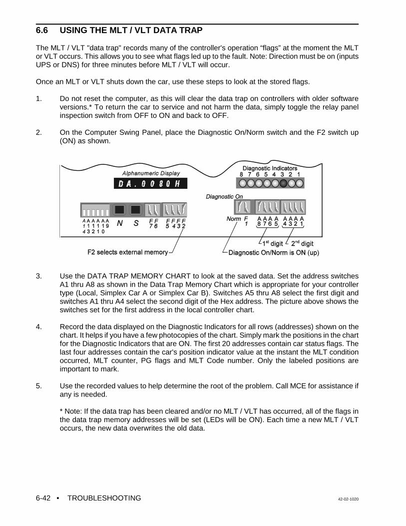
• TROUBLESHOOTING 42-02-10206-42
6.6 USING THE MLT / VLT DATA TRAP
The MLT / VLT "data trap" records many of the controller's operation “flags” at the moment the MLTor VLT occurs. This allows you to see what flags led up to the fault. Note: Direction must be on (inputsUPS or DNS) for three minutes before MLT / VLT will occur.
Once an MLT or VLT shuts down the car, use these steps to look at the stored flags.
1. Do not reset the computer, as this will clear the data trap on controllers with older softwareversions.* To return the car to service and not harm the data, simply toggle the relay panelinspection switch from OFF to ON and back to OFF.
2. On the Computer Swing Panel, place the Diagnostic On/Norm switch and the F2 switch up(ON) as shown.
3. Use the DATA TRAP MEMORY CHART to look at the saved data. Set the address switchesA1 thru A8 as shown in the Data Trap Memory Chart which is appropriate for your controllertype (Local, Simplex Car A or Simplex Car B). Switches A5 thru A8 select the first digit andswitches A1 thru A4 select the second digit of the Hex address. The picture above shows theswitches set for the first address in the local controller chart.
4. Record the data displayed on the Diagnostic Indicators for all rows (addresses) shown on thechart. It helps if you have a few photocopies of the chart. Simply mark the positions in the chartfor the Diagnostic Indicators that are ON. The first 20 addresses contain car status flags. Thelast four addresses contain the car's position indicator value at the instant the MLT conditionoccurred, MLT counter, PG flags and MLT Code number. Only the labeled positions areimportant to mark.
5. Use the recorded values to help determine the root of the problem. Call MCE for assistance ifany is needed.
* Note: If the data trap has been cleared and/or no MLT / VLT has occurred, all of the flags inthe data trap memory addresses will be set (LEDs will be ON). Each time a new MLT / VLToccurs, the new data overwrites the old data.

42-02-1020 TROUBLESHOOTING • 6-43
GED
DOI
SDT
LOT
STU
UDP
CCA
RUN
ISRT
FRC
TFD
PFG
EP1
PI
GEU
DHO
CCT
STD
FWI
PK
UCA
DSH
ISV
FRAS
USD
EP2
PI
SE
HCT
NUDG
UPS
EXMLT
LU
DCA
CCD
FRSS
SUA
HSEL
CTL
ESSI
PI
DBC
DCC
DNS
HLI
IN
UPDO
DMU
H
HCDX
FRM
SU
ISR
CTLF
ESSH
PI
DOL
CC
DSHT
CSB
FRS
HLW
IND
DDP
CCB
SST
HCR
BFD
SLV
LLI
CD3
PI
DZ
UC
DOF
FCS
SP1
VCA
DCLC
UCB
VLT
SAF
DSD
LLW
ECRN
PI
PHE
DC
DCP
FRA
SP2
UFP
DLK
LD
DCB
MLT
STC
SDA
CCC
HLD
PI
DOLM
DCF
VCI
LFP
SUD
DNDO
DMD
TOS
SD
PTI
EPR
PI
HMC HYDRO (LOCAL) MLT /VLT DATA TRAP MEMORY CHART
ComputerMemoryAddress
(Hex) Diagnostic On F1 A8.......A5 A4.......A1
80
81
82
83
84
85
86
87
88
89
8A
8B
8C
8D
8E
8F
90
91
92
93
94
95
97
Diagnostic IndicatorsLED On = variable flag is On or Active
8
Toggle Switches
DZORDZ
DNmd 028
1234567
CODE #CODE #CODE # CODE #
Counter Counter Counter Counter Counter Counter
CODE # CODE # CODE # CODE #
Counter Counter

• TROUBLESHOOTING 42-02-10206-44
GED
DOI
SDT
HSEL
STU
UDP
CCA
RUN
ISRT
FRC
TFD
PFG
PI
GEU
DHO
CCT
STD
FWI
PK
UCA
DSH
ISV
FRAS
USD
EPR
PI
SE
HCT
NUDG
UPS
EXMLT
LU
DCA
CCD
FRSS
SUA
CD
CTL
PI
DBC
DCC
DNS
HLI
IN
UPDO
DMU
H
HCDX
FRM
SU
ECRN
CTLF
CD4
PI
DOL
CC
DSHT
CSB
FRS
HLW
IND
DDP
CCB
SST
HCR
BFD
ATSF
LLI
CD3
PI
DZ
UC
DOF
LOT
FCS
SP1
VCA
DCLC
UCB
VLT
SAF
DSD
LLW
PI
PHE
DC
DCP
FRA
SP2
UFP
DLK
LD
DCB
MLT
STC
SDA
HLD
PI
DOLM
DCF
VCI
LFP
SUD
DNDO
DMD
TOS
SD
PI
HMC HYDRO (SIMPLEX CAR A) MLT / VLT DATA TRAP MEMORY CHART
ComputerMemoryAddress
(Hex)Diagnostic On F1 A8.......A5 A4.......A1
C0
C1
C2
C3
C4
C5
C6
C7
C8
C9
CA
CB
CC
CD
CE
CF
D0
D1
D3
D4
D5
D6
D7
Diagnostic IndicatorsLED On = variable flag is On or Active
8
Toggle Switches
DZORDZ
DNmd 029
1234567
CODE #CODE #CODE # CODE #
Counter Counter Counter Counter Counter Counter
CODE # CODE # CODE # CODE #
Counter Counter
HEPART

42-02-1020 TROUBLESHOOTING • 6-45
GED
DOI
SDT
HSEL
STU
UDP
CCA
RUN
ISRT
FRC
TFD
PFG
PI
GEU
DHO
CCT
STD
FWI
PK
UCA
DSH
ISV
FRAS
USD
EPR
PI
SE
HCT
NUDG
UPS
EXMLT
LU
DCA
CCD
FRSS
SUA
CD
CTL
PI
DBC
DCC
DNS
HLI
IN
UPDO
DMU
H
HCDX
FRM
SU
ECRN
CTLF
CD4
PI
DOL
CC
DSHT
CSB
FRS
HLW
IND
DDP
CCB
SST
HCR
BFD
ATSF
LLI
CD3
PI
DZ
UC
DOF
LOT
FCS
SP1
VCA
DCLC
UCB
VLT
SAF
DSD
LLW
PI
PHE
DC
DCP
FRA
SP2
UFP
DLK
LD
DCB
MLT
STC
SDA
HLD
PI
DOLM
DCF
VCI
LFP
SUD
DNDO
DMD
TOS
SD
PI
HMC HYDRO (SIMPLEX CAR B) MLT DATA TRAP MEMORY CHART
ComputerMemoryAddress
(Hex)Diagnostic On F1 A8.......A5 A4.......A1
E0
E1
E2
E3
E4
E5
E6
E7
E8
E9
EA
EB
EC
ED
EE
EF
F0
F1
F3
F4
F5
F6
F7
Diagnostic IndicatorsLED On = variable flag is On or Active
8
Toggle Switches
DZORDZ
DNmd 030
1234567
CODE #CODE #CODE # CODE #
Counter Counter Counter Counter Counter Counter
CODE # CODE # CODE # CODE #
Counter Counter
HEPART


42-02-1020 APPENDIX A - DISASSEMBLING THE COMPUTER SWING PANEL • A-1
CAUTION: Components on the PC boards can be damaged by ESD.Install a grounding strap on your wrist and connect it toground before handling the PC boards.
APPENDIX ADISASSEMBLING THE COMPUTER SWING PANEL
MCE Technical Support may advise an installer to remove a circuit board for troubleshootingreasons. If so, remove the thumbscrew holding the Swing Panel to the bracket on the backplate. Open the Swing Panel , exposing the back cover plate.
Loosen and remove the four nuts securing the back cover plate. This may require the use ofa 11/32 nut driver.
Disconnect the 20 pin ribbon cables from the HC-PI/O and MC-RS boards.
Remove the circuit boards from the Swing Panel. Put the nuts back on the bolts forsafekeeping.
Unsnap the boards from each other and replace/repair the boards as necessary.

• APPENDIX B - CHANGING PC BOARDS, EPROMS OR MICROCONTROLLERS 42-02-1020A-2
CAUTION: Components on the PC boards can be damaged by ESD.Install a grounding strap on your wrist and connect it toground before handling the PC boards.
APPENDIX BCHANGING PC BOARDS, EPROMS ORMICROCONTROLLERS
With directions from MCE Technical Support, a PC board, EPROMs or Microcontroller mayneed to be reinstalled in the field. Great care should be taken when changing any of theseitems. The EPROM stores the computer program, the microcontroller both stores and executesthe program and all three are subject to damage by ESD (see CAUTION). These instructionsshould be followed step-by-step.
B.1 REPLACING THE MAIN PROCESSOR BOARD OR EPROM
Normally the microprocessor on the Main Processor board (MC-MP-1ES or MC-MP2) is notreplaced in the field. Sometimes the EPROM is replaced to upgrade the program andoccasionally the complete board must be replaced due to a component failure.
Replacing the EPROM - The EPROM for the MC-MP-1ES board is labeled S-MP-xx-1. TheEPROM for the MC-MP2 board is labeled S-MP2-xx-1. The “xx” represents the controller type.If the new EPROM has the same job number as the old EPROM, the user settings for timersand adjustable control variables, etc., are retained. Any new timers or variables added to thenew EPROM will be set to their default values.
If the job number on the new EPROM is different from the job number on the old EPROM, allof the timers and variables will be set to their default values. The user settings should bedocumented before the old EPROM is removed so that they can be re-entered when the newEPROM is installed.
Replacing the Main Processor board - The user settings for timer and adjustable controlvariables are stored in battery backed RAM on the Main Processor board. If the new board waspreviously installed in another car controller, the user settings from that car will be retained. Ifthe new board is a replacement from MCE, all of the user programmable values will be set totheir default values. Therefore, the current user settings should be documented before the oldboard is removed so that they can be re-entered when the new board is installed. The followingis a list of the user settings:
C Elevator Timers (see Section 5.2.3)C Real Time Clock Flags (see Section 5.2.4)C Communications Port Settings (see Section 5.3.1)C Security Codes (see Section 5.3.2)C Master Software Key (MSK) (see Section 5.3.3)C Software Options - Adjustable Control Variables (see Section 5.3.4)

42-02-1020 APPENDIX B - CHANGING PC BOARDS, EPROMS OR MICROCONTROLLERS • A-3
Replacement Procedure
1. Document the current settings for the items listed above.
2. Turn power OFF at the main disconnect and verify that no lights are operating on themicroprocessor panel. Install a grounding strap on your wrist and connect it to groundbefore handling the PC boards.
3. Remove the Main Processor board (MC-MP-1ES or MC-MP2) from the Swing Panel.Refer to Appendix A for instructions on unloading the boards from the Swing Panel. Ifyou are replacing the PC board, proceed to step 6 below (refer to Figure 6.20 or 6.21for proper jumper settings.
4. Using a small, thin-bladed screwdriver, place the tip between the EPROM chip and itssocket, not between the socket and the board (see Figure 6.20 or 6.21). Gently pry theexisting EPROM out from the socket. Do this very slowly, taking care not to bend theleads. If they become bent, straighten them carefully with needlenose pliers.
5. Place the new EPROM lightly (do not plug it in yet) into the socket and check to see thatall pins are aligned with their corresponding holes in the socket. Also make sure that thenotch on the end of the EPROM is correctly aligned with the notch on the socket (theorientation of the notch should also correspond to the notches on all of the other chipson the board). Now push the EPROM firmly into the socket and make sure that noneof the pins are bent during the insertion. Inspect the EPROM to make sure that no pinsare bent outward or under the EPROM.
6. Reassemble the Swing Panel assembly and close the Swing Panel. Refer to theinstructions in Appendix A.
7. Turn power ON at the main disconnect. Verify the proper operation of all boards byinspecting the diagnostic indicators and Computer ON LEDs on the individual processorboards.
C If the Computer ON LEDs are not illuminated on all boards, the EPROMs maynot have been installed properly. Repeat the above steps 2 through 7.
8. Re-enter the user settings documented in step 1 above.
B.2 REPLACING THE MC-CGP-4 (8) BOARD OR EPROMS
Sometimes the EPROMs are replaced to upgrade the program to a new software version andoccasionally the complete board must be replaced for a software upgrade or a componentfailure.
Replacing the EPROMs - The EPROMs for the MC-CGP-4 (8) board are labeledS-CGP-CC-1 and S-CGP-CC-2. i) EPROMs with the same software version number will not cause the loss of user data.
Follow steps 2 thru 7 in the Replacement Procedure below. ii) EPROMs with a new software version number will result in loss of user data. Follow the
entire Replacement Procedure below.
Replacing the MC-CGP-4 (8) board - The user settings for the items listed below are storedin battery backed RAM on the MC-CGP-4 (8) board. If the new board was previously installedin another car controller, the user settings from that car will be retained. Follow the entire

• APPENDIX B - CHANGING PC BOARDS, EPROMS OR MICROCONTROLLERS 42-02-1020A-4
Replacement Procedure below when using a board from another car controller which hasdifferent settings from those of the car being replaced or when installing a board from MCE.
NOTE: The Fault Log and Performance Reports will all be lost and can not be recovered.
Replacement Procedure
1. Document the current settings for the items listed below.
C M3 Group Parameters or Car ID parameter CNID on F1 -1 screen for local cars onlyC Security - timer tables, security configurations, passenger names and access codes
(simplex car and group only)C Special Events Calendar Menu options Configure by Type, Configure by Controller,
and CMS Com Port Setup (if available)C Job Configuration data used for display - job name, car label and landing labels
2. Turn power OFF at the main disconnect and verify that no lights are operating on themicroprocessor panel. Install a grounding strap on your wrist and connect it to groundbefore handling the PC boards.
3. Remove the MC-CGP-4 (8) board from the Swing Panel. Refer to Appendix A forinstructions on unloading the boards from the Swing Panel. If you are replacing the PCboard, proceed to step 6 below (refer to Figure 6.22 for proper jumper settings).
4. The two EPROMs on the MC-CGP-4 (8) board are labeled ROM1-U17 and ROM2-U18(see Figure 6.22) Using a small, thin-bladed screwdriver, place the tip between theEPROM chip and its socket, not between the socket and the board. Gently pry theexisting EPROMs out from the socket. Do this very slowly, taking care not to bend theleads. If they become bent, straighten them carefully with a needlenose pliers.
5. Place the new EPROMs lightly (do not plug it in yet) into the sockets and check to seethat all pins are aligned with their corresponding holes in the socket. Also make surethat the notch on the end of the EPROM is correctly aligned with the notch on thesocket (the orientation of the notch should also correspond to the notches on all of theother chips on the board). Now push the EPROMs firmly into the socket and make surethat none of the pins are bent during the insertion. Inspect the EPROMs to make surethat no pins are bent outward or under the EPROM.
6. Reassemble the Swing Panel assembly and close the Swing Panel. Refer to theinstructions in Appendix A.
7. Turn power ON at the main disconnect. Verify the proper operation of all boards byinspecting the diagnostic indicators and Computer ON LEDs on the individual processorboards.
C If the Computer ON LEDs are not illuminated on all boards, the EPROMs maynot have been installed properly. Repeat the above steps 2 through 7.
C Verify that the group controller is communicating with the cars by looking at theLEDs in the front of the group swing panel.
8. Set ODPC=ON, on the General F1-1 screen, and save the parameter, or reset theMC-CGP parameters as described in Section 5.2.6.
9. Re-enter the user settings documented in step 1 above.

42-02-1020 APPENDIX C - NOMENCLATURE • A-5
APPENDIX CNOMENCLATURE
Motion Control Engineering, Inc.
NOMENCLATURE
F:\DOCS\Nmcltr1Shipping.frm Effective Date: 11/27/00 Approved By: Engineering Manager Page 1 of 2
# PC BOARD DESCRIPTION 1 HC-RB4 Traction Controller Main Relay Board1 HC-RBH Hydraulic Controller Main Relay Board2 HC-CI/O Non Programmable Controller Call I/O Board2 HC-CI/O-E Programmable Controller Call I/O Expander Board3 HC-PI/O Non Programmable Controller Power I/O Board (Car A) â3 HC-PCI/O Programmable Controller Power And Call I/O Board4 HC-PI/O Non Programmable Controller Power I/O Board (Car B) â6 HC-TAB Traction Adapter Board7 HC-RDRB Rear Door Relay Board8 HC-RD Rear Door Logic Board (Car A) â9 HC-RD Rear Door Logic Board (Car B)
10 HC-DB-MOD Front G.A.L. MOD Door Interface Board11 HC-DB-MOD-R Rear G.A.L. MOD Door Interface Board12 HC-DPS Door Power Supply Board13 HC-PIX Position Indicator Expander Board (Car A) â14 HC-PIX Position Indicator Expander Board (Car B)15 HC-SRT Suicide Relay Timing Board16 HC-SCR SCR Interface Board17 HC-EQ Earthquake Board18 HC-IOX I/O(8 Input / 8 Output) Expander Board (Car A) â19 HC-IOX I/O(8 Input / 8 Output) Expander Board (Car B)20 HC-IOX Additional I/O(8 Input / 8 Output) Expander Board (Car A) â21 HC-IOX Additional I/O(8 Input / 8 Output) Expander Board (Car B)26 HC-DYNA Dynalift Interface Board27 MC-ACFR AC Feedback Relay Board28 IMC-GIO General Turbo DF I/O Board29 IMC-RB Turbo DF Relay Board30 HC-DB-MOM/H Front G.A.L. MOM/MOH Door Interface Board31 HC-DB-MOM/H-R Rear G.A.L. MOM/MOH Door Interface Board32 HC-OA Output Adapter Board33 IMC-RI M/G Relay Interface Board34 IMC-PRI M/G Power Relay Interface Board35 IMC-DIO Digital I/O Board36 IMC-DAS Data Acquisition Board37 HC-I4O I/O(16 Input /4 Output) Expander Board (Car A) â38 HC-I4O I/O(16 Input /4 Output) Expander Board (Car B)39 HC-I4O Additional I/O(16 Input / 4 Output) Expander Board (Car A) â40 HC-I4O Additional I/O(16 Input /4 Output) Expander Board (Car B)41 SCR-RI SCR/AC Relay Interface Board42 SCR-PRI SCR/AC Power Relay Interface Board43 HC-LB Lock Bypass Board44 HC-GB Gong Board45 HC-GB Additional Gong Board46 HC-SIB Selectable Input Buffer Board (Car A) â47 HC-SIB Selectable Input Buffer Board (Car B)48 HC-RT Relay Tester Board49 IMC-ACIB AC Baldor Interface Board50 HC-DPS-MOM/H Front G.A.L. MOM/MOH Door Interface and Power Supply Board51 HC-ACI AC Drive Interface Board52 HC-ACIF AC Flux Vector Interface Board

# PC BOARD DESCRIPTION
• APPENDIX C - NOMENCLATURE 42-02-1020A-6
53 HC-DPS-MOM/H-R Rear G.A.L. MOM/MOH Interface and Power Supply Board54 IMC-MBX IMC Enhanced Motherboard55 SCR-RIX SCR Relay Interface Extension Board56 HC-HBF A.S.M.E. Front Door Lock Bypass Board57 HC-HBFR A.S.M.E Front and Rear Door Lock Bypass Board
58 IMC-ACIM AC MagneTek Interface Board
59 HC-TACH-MG Tach Adjust Board for VVMC-MG Controller
60 HC-TACH-SCR Tach Adjust Board for VVMC-SCR Controllerâ Individual group cars use board numbers for car A only

42-02-1020 INDEX • I-1
INDEX2ND LANDING AUX. ACCESS FAULT message, 6-5, 6-9
A
absolute floor encoding, description of, 4-2ADAC, ADA Car Call Door Dwell Timer, 5-7ADAH, ADA Hall Call Door Dwell Timer, 5-7AFR, Alternate Fire Floor Recall, 5-16AFR2, Second Alternate Fire Floor Recall, 5-16Alarm - No Car Movement message, 6-9Alarm - No Door Zone message, 6-9AlmNoDZ, car operation message, 6-9AlmNoMv, car operation message, 6-9alphanumeric display, Swing Panel, 5-2
viewing the MP flags, 5-9ALT, Alternate Service flag, 5-26AltFir1, car operation message, 6-9, 6-13Anti-Nuisance Operation message, 6-10AntiNui, car operation message, 6-9, 6-10APP1, Alternate Primary (lower) Parking Floor, 5-16APP2, Alternate Primary (lower) Parking Floor #2, 5-16ASP1, Alternate Secondary (upper) Parking Floor, 5-16ASP2, Alternate Secondary (upper) Parking Floor #2, 5-16ATSF, Attendant Service Function flag, 5-26ATTENDANT SERVICE OPERATION message, 6-5, 6-10AttnSrv, car operation message, 6-9, 6-10Automatic Operation message, 6-10AutoOps, car operation message, 6-9, 6-10AUX. INSPECTION ACCESS FAULT message, 6-5, 6-10
B
BFD, Bottom Floor Demand flag, 5-26BflrDem, car operation message, 6-9, 6-10Both USD and DSD Are Open message, 6-10BOTH USD AND DSD INPUTS ARE ACTIVE message,
6-5, 6-10Bottom Floor Demand message, 6-10
F3 screen (BflrDem), 6-9BOTTOM FLOOR OR TOP FLOOR DEMAND message,
6-5, 6-10, 6-18BOTTOM LANDING AUX. ACCESS FAULT message,
6-5, 6-10BSI, Building Security Input flag, 5-26Byp-HLW, car operation message, 6-9, 6-14
C
call circuits, troubleshooting, 6-35call logic, troubleshooting, 6-32-34Car Call Bus Fuse Blown message, 6-10CAR CALL BUS IS DISCONNECTED message, 6-5, 6-10Car Communication Control (CCC)
MC-CGP-x Board Quick Reference, 6-38MC-RS Board Quick Reference, 6-39
Car Communication Control (COC)description of, 1-10
Car Controller Physical Layout, 1-2CAR IN TEST MODE message, 6-5, 6-17Car is Overloaded message, 6-11Car Network ID, setting, 4-6
Car Operation Control (COC)call logic troubleshooting, 6-32-34description of, 1-8-10door logic troubleshooting, 6-26HC-CI/O Board Quick Reference, 6-33inputs and outputs, 1-8-10MC-MP-1ES Board Quick Reference, 6-36MC-MP2 Board Quick Reference, 6-37troubleshooting, tracing signals, 6-27, 6-28
Car Out of Service with Doors Locked message, 6-11Car Out of Service without Doors Locked message, 6-11Car Performance Graph (F11, 8) screen, 6-25Car Performance Report (F11, 8, H) screen, 6-25CAR SAFETY DEVICE OPEN message, 6-5, 6-11Car to Lobby message, 6-11CAR TO LOBBY OPERATION message, 6-5, 6-11CC, Car Call flag, 5-26CCA, Car Call Above flag, 5-26CCB, Car Call Below flag, 5-26CCBC, Cancel Car Call Behind Car Option, 5-16CCC, Car Call Cancel flag, 5-26CCD, Car Call Disconnect flag, 5-26CCT, Car Call Door Dwell Timer, 5-7CCT, Car Call Door Time flag, 5-26CD, Car Done flag, 5-26CD3, Third Bit in Absolute PI Code flag, 5-26CD4, Fourth Bit in Absolute PI Code flag, 5-26clock, setting, 5-9CNID, Car Network ID option, 5-16Communication Loss message, 6-11communication ports, setting, 5-12, 5-13computer flags
DDP flag addresses, 5-29MP flags, 5-26viewing the DDP flags, 5-26viewing the MP flags, 5-24, 5-26
computer reset button, 5-1, 5-2Computer Swing Panel
alphanumeric display, 5-2computer reset button, 5-1, 5-2DDP Diagnostic Indicators, 5-6description of, 1-2, 1-3, 5-1-3diagnostic indicators, 5-2, 5-5diagnostic mode, 5-24, 5-26digital drive diagnostic indicators, 5-3disassembling, A-1Enhanced On-Board Diagnostics (EOD), 5-1-3normal mode, 5-5-7replacing EPROMs or PC boards, A-2-4status indicators, 5-2system mode, 5-12, 5-13, 5-16, 5-18
CONTACTOR PROOFING REDUNDANCY FAILUREmessage, 6-5, 6-11
controllerenvironmental considerations, 2-1final adjustments, 4-4functional layout, 1-9ground wiring, 2-4, 2-5initial adjustments, 3-2installation of, 2-3, 2-4physical layout, 1-2proper grounding, 2-4site selection, 2-1wiring, 2-3, 2-4

• INDEX 42-02-1020I-2
wiring prints, 2-2CPPB, Constant/Momentary Pressure Photo Eye/Safety
Edge Bypass, 5-16CSAR, CSA Redundancy Check Option, 5-16CSB, Car Stop Switch Bypass Output flag, 5-26CTL, Car to Lobby Input flag, 5-26CTLF, Car to Lobby Function Flag, 5-26
D
DBC, Door Button Close Input flag, 5-26DBT, Door Buzzer Timer, 5-7DC, Down Call flag, 5-26DCA, Down Call Above flag, 5-26DCB, Down Call Below flag, 5-26DCC, Door Close Complete flag, 5-26DCF, Door Close Function Output flag, 5-26DCFL, Door Close Front Latch option, 5-16DCL, Door Closed Limit Flag, 5-31DCLD, Door Closed Contact Input flag, 5-26DCLR, Rear Door Closed Limit Flag, 5-31DCP, Door Closed Power Output flag, 5-26DCRL, Door Close Rear Latch option, 5-16DDOP, Double Ding on Down Option, 5-17DDP Diagnostic Indicators, 5-6DDP, Down Direction Preference flag, 5-26DDPO, Door Lock Direction Preference Option, 5-17DGNG, Door Lock Gong Option, 5-17DHLD, Door Hold Timer, 5-7DHO, Door Hold Open flag, 5-26diagnostic indicators, 5-2, 5-5
MP status and error messages, 6-3Diagnostic Mode (EOD)
description of, 5-24, 5-26viewing the DDP flags, 5-26viewing the MP flags, 5-24, 5-26
Diagnostics Menu (F11) screen, 6-23digital drive diagnostic indicators, 5-3DIRECTION RELAY REDUNDANCY FAILURE message,
6-5DLK, Door Lock Input flag, 5-26DLW, Dispatch load weigher threshold, 5-18DMD, Demand Down flag, 5-26DMU, Demand Up flag, 5-26DNDO, Down Direction Output flag, 5-26DNS, Down Direction Sense Input flag, 5-26DOF, Door Open Function Output flag, 5-26DOFL, Door Open Front Latch option, 5-17DOI, Door Open Intent flag, 5-26DOL AND DLK BOTH ACTIVE message, 6-5, 6-12DOL, Door Open Limit Input flag, 5-26DOLM, Door Open Limit Memory flag, 5-26DOOR CLOSE FAILURE message, 6-5, 6-11Door Close Protection message, 6-11Door Lock Contact Failure message, 6-11DOOR LOCK FAILURE message, 6-5, 6-11Door Lock Relay Redundancy Failure message, 6-12DOOR LOCK SWITCH FAILURE message, 6-5, 6-11door logic
troubleshooting, 6-26troubleshooting, tracing signals, 6-27, 6-28
DOOR OPEN LIMIT FAILURE message, 6-5, 6-12Door Open Protection message, 6-12Door Position Monitor switch, 2-7Door Sequence of Operation Flowchart, 6-28Door Zone Sensor Failure (active state) message, 6-12DOOR ZONE SENSOR FAILURE message, 6-5, 6-12
door zone sensors, troubleshooting, 6-27, 6-28Doors Locked but not fully Closed - Front message, 6-12Doors Locked but not fully Closed - Rear message, 6-12Doors Open And Locked message, 6-12DORL, Door Open Rear Latch, 5-17DPM REDUNDANCY FAULT message, 6-5, 6-12DPMR REDUNDANCY FAULT message, 6-5, 6-13drawing numbers, description of, 2-2DRIVE FAILED TO RESPOND message, 6-5DSD, Down Slow Down Input flag, 5-26DSH, Door Shortening (Car Call Button Pushed) flag, 5-26DSHT, Door Shortening (Final) flag, 5-26DZ, Door Zone Input flag, 5-26DZORDZ, Door Zone or Rear Door Zone flag, 5-26
E
Earthquake message, 6-13F3 screen (Eqactv), 6-9
EARTHQUAKE OPERATION message, 6-5, 6-13ECRN, Emergency Power Running Car flag, 5-26elevator security
programming the security codes, 5-15Elevator Shutdown or Power Transfer message, 6-13ELEVATOR SHUTDOWN SWITCH OR POWER
TRANSFER INPUT ACTIVE message, 6-5, 6-13elevator timers
description of, 5-7setting, 5-7
Emergency Power message, 6-13F3 screen (EmergPwr), 6-9
EMERGENCY POWER OPERATION message, 6-5, 6-13EMERGENCY POWER SHUTDOWN message, 6-5, 6-13EMERGENCY STOP INPUT 1 ACTIVATED message,
6-5, 6-13EMERGENCY STOP INPUT 2 ACTIVATED message,
6-5, 6-13EmrgPwr, car operation message, 6-13Enhanced On-Board Diagnostics (EOD)
alphanumeric display, 5-2DDP Diagnostic Indicators, 5-6diagnostic indicators, 5-2, 5-5diagnostic mode, 5-24, 5-26digital drive diagnostic indicators, 5-3MP flag addresses, 5-29MP flags, 5-26MP status and error messages, 6-3normal mode, 5-5-7, 5-9overview, 5-1-3status indicators, 5-2system mode, 5-12, 5-13, 5-16, 5-18
ENTER SECURITY CODE message, 6-5, 6-17environmental considerations, 2-1EPI, Emergency Power Input flag, 5-26EPR, Emergency Power Return Function flag, 5-26EPROMS, replacing, A-1-4Eqactv, car operation message, 6-13ESSH, Elevator Shutdown Switch Flag, 5-26ESSI, Elevator Shutdown Switch Input flag, 5-26EXMLT, Bottom Floor Recall Input flag, 5-26External Motor Limit Timer message, 6-13

42-02-1020 INDEX • I-3
F
F3 screenCAR OPERATION messages, 6-9
FAILURE TO LEAVE THE FLOOR message, 6-5FCS, Fire Phase II Input flag, 5-26final adjustments
hydraulic valves, 4-5registering car calls, 4-3setting the Car Network ID, 4-6slowdown and limit switches, 4-5test mode operation, 4-3
Fire Phase II , 4-5Fire Return Phase 1, 4-5Fire Service Alternate message, 6-13Fire Service Main message, 6-13Fire Service Operation
F3 screen (AltFir1) message, 6-9F3 screen (FirePh2) message, 6-9F3 screen (MnFire1) message, 6-9
FIRE SERVICE PHASE 1 - ALTERNATE message, 6-5,6-13
FIRE SERVICE PHASE 1 - MAIN message, 6-6, 6-13FIRE SERVICE PHASE 2 message, 6-6, 6-14FirePh2, car operation message, 6-9, 6-14Flex-talk option, A-7-9
diagnostics, A-8troubleshooting, A-9
FLO, Fan and Light Output Timer, 5-8FLT Relay Dropped message, 6-14FRA, Alternate Fire Phase I Input flag, 5-26FRC, Fire Phase II flag, 5-26FRONT DOOR IS LOCKED BUT NOT FULLY CLOSED
message, 6-6, 6-12FRS, Fire Phase I Input flag, 5-26function switches, 5-3FWI, Fire Warning Indicator Output flag, 5-26
G
GATE SWITCH FAILURE message, 6-6, 6-14Gate Switch Relay Redundancy Failure message, 6-14GED, Gong Enable Down Output flag, 5-26GEU, Gong Enable Up Output flag, 5-26GOVERNOR SWITCH OPEN message, 6-14ground
ground test, 3-1wiring, 2-4, 2-5
H
H, High Speed Output flag, 5-26Hall Call Bus Fuse Blown message, 6-14HALL CALL BUS IS DISCONNECTED message, 6-6,
6-14Hall Call Bypass Operation message, 6-14HC-CI/O, Call Input/Output Board
inputs and outputs, 1-9, 1-10PCB layout and description of, 1-6Quick Reference, 6-33troubleshooting, 6-32-34
HC-I4O, Input/Output Expander BoardPCB layout and description of, 1-6
HC-IOX, Input Output Expander BoardPCB layout and description of, 1-6
HC-IPLS IP Landing System Board Quick Reference, 6-40
HC-PI/O, Power Input/Output Boardinputs and outputs, 1-10PCB layout and description of, 1-5Quick Reference, 6-30troubleshooting, 6-26-28
HC-PIX ,Position Indicator Expander BoardPCB layout and description of, 1-5
HC-RBH, Main Relay BoardPCB layout and description of, 1-7
HCR, Hall Call Reject flag, 5-26HCT, Hall Call Door Dwell Timer, 5-8HCT, Hall Call Door Time flag, 5-26Heavy Load message, 6-14HEAVY LOAD WEIGHER CONDITION message, 6-6, 6-
14HLD, Hold Input Fire Phase II flag, 5-26HLI, Heavy Load Input flag, 5-26HLW, Heavy Load Weigher flag, 5-26HLW, Heavy load weigher threshold, 5-18HML, Home Landing Select Input flag, 5-26HOISTWAY SAFETY DEVICE OPEN message, 6-6, 6-14HOS2, In-car Hospital Service Timer, 5-8Hospital Emergency Operation
F3 screen (HospEmr) message, 6-9, 6-14, 6-15HOSPITAL PHASE 1 OPERATION message, 6-6, 6-14HOSPITAL PHASE 2 OPERATION message, 6-6, 6-15Hospital Service message, 6-14Hospital Service Phase 2 message, 6-15HREO, Reopen doors with hall button option, 5-17HSEL, Hospital Emergency Select flag, 5-26
I
IN CAR STOP SWITCH ACTIVATED message, 6-6, 6-15IN, Inspection or Access Input flag, 5-26In-car Hospital Service Timer (HOS2), 5-8In-car Stop Switch message, 6-15Inconspicuous Riser message, 6-15IND, Independent Service Input flag, 5-26Independent Service message, 6-15
F3 screen (IndSrv), 6-9INDEPENDENT SERVICE OPERATION message, 6-6,
6-15IndSrv, car operation message, 6-15input / output status
viewing status flags, 5-9InServ, car operation message, 6-9InspAcc, car operation message, 6-15Inspection message, 6-15Inspection operation, 3-3
F3 screen (InspAcc) message, 6-9INSPECTION OPERATION message, 6-6, 6-15ISR, In Service and Ready flag, 5-26ISRT, In Service Truly flag, 5-26ISV, In Service flag, 5-26
K
KCE, Keyboard Control of Elevators, 5-17

• INDEX 42-02-1020I-4
L
Landing Systemdescription of, 1-11installation of, 2-5, 2-6installation of magnets, 2-6
LANDING SYSTEM REDUNDANCY FAILURE message,6-6, 6-15
LBBY, Lobby Floor, 5-17LD, Level Down Input flag, 5-26
learn operationsload weigher learn operation, 5-18
Level Down message, 6-15Level Up message, 6-15LEVELING DOWN message, 6-6, 6-15LEVELING SENSOR FAILED - OFF POSITION message,
6-6, 6-15LEVELING SENSOR FAILED - ON POSITION message,
6-6, 6-15Leveling Sensor Failure (Active State) message, 6-15Leveling Sensor Failure (Inactive State) message, 6-15LEVELING SENSOR FAILURE message, 6-6, 6-16Leveling Sensor Redundancy Failure message, 6-16LEVELING UP message, 6-6, 6-15LFP, Lower Floor Parking flag, 5-26LGNG, Lobby Alternate Gong Option, 5-17Light Load message, 6-16LIGHT LOAD WEIGHER CONDITION message, 6-6, 6-16limit switches, installation of, 2-5LLCC, Light Load Call Cancel, 5-17LLI, Light Load Input flag, 5-26LLW, Light Load Weigher flag, 5-26LLW, Light load weigher threshold, 5-18Lost Door Lock During Run message, 6-16LOT, Lobby Call Door Dwell Timer, 5-8LOT, Lobby Door Time flag, 5-26Low Oil Switch message, 6-16LS-QUTE
description of, 1-11installation of, 2-6
LS-STAN, description of, 1-11LU, Level Up Input flag, 5-26
M
MC-CGP-4, Communication Processor Boardcomputer ON LED, 5-3PCB layout and description of, 1-4Quick Reference, 6-38replacing EPROMs or PC board, A-1, A-3, A-4
MC-MP-1ES, Main Processor Boardcomputer reset button, 5-1, 5-2diagnostic indicators, 5-2MP flag addresses, 5-29PCB layout and description of, 1-3Quick Reference, 6-36replacing EPROM or PC board, A-1-3status and error messages, 6-3status indicators, 5-2
MC-MP2, Main Processor BoardMP flags, 5-26Quick Reference, 6-37
MC-RS, Communication Interface BoardPCB layout and description of, 1-4Quick Reference, 6-39
Mechanical Safety Edge Protection Timer (SEPT), 5-8MFR, Main Fire Floor Recall, 5-17MLT, car operation message, 6-9, 6-16MLT, Motor Limit Timer flag, 5-26MnFire1, car operation message, 6-9, 6-13MOTOR LIMIT TIMER (ANTI-STALL) ELAPSED message,
6-6, 6-13, 6-16, 6-18Motor Limit Timer message, 6-16motor starter counter, description of, 5-5MP Input/Output (F11,7) screen, 6-24MSAF, Mechanical Safety Edge, 5-17
N
Network Status (F11, 1) screen, 6-23nomenclature
description of, 2-2for PC boards, A-5
Normal Mode (EOD)DDP Diagnostic Indicators, 5-6description of, 5-5-7diagnostic indicators, 5-5setting elevator timers, 5-7setting the processor clock, 5-9
NORMAL OPERATION message, 6-6NPRE, No Pre-opening Option, 5-17NUDG, Nudging Output flag, 5-26Nudging message, 6-16Nudging, car operation message, 6-9, 6-16
O
OLW, Overloaded car threshold, 5-19OLW2, Overloaded car threshold 2, 5-19Out of Service message, 6-16OutServ, car operation message, 6-9, 6-16OVERLOAD CONDITION message, 6-6, 6-11
P
PASSCODE REQUEST message, 6-6, 6-16Passcode Requested message, 6-16Passcode Requested option, 5-23PC boards, nomenclature for, A-5PECC, Anti-nuisance Call Cancel, 5-17PFG, Passing Floor Gong flag, 5-26PHE, Photo Eye Input flag, 5-26PHEB, Photo Eye Bypass Timer, 5-8PHEP, Photo Eye Protection, 5-17PHOTO EYE FAILURE message, 6-6, 6-16photo eye input, troubleshooting, 6-29Photo-Eye Failure (Front) message, 6-16Photo-Eye Failure (Rear) message, 6-16Photo-Eye Failure message, 6-16PK, Parking flag, 5-26Power Down message, 6-17power supply, description of, 1-8PPF, Primary (lower) Parking Floor, 5-17PRE-TEST MODE message, 6-6, 6-17PRESSURE SWITCH ACTIVATED message, 6-6, 6-17PRIORITY / VIP SERVICE - PHASE 1 message, 6-6, 6-17PRIORITY / VIP SERVICE - PHASE 2 message, 6-6, 6-17Priority/VIP Service Phase 1 message, 6-17Priority/VIP Service Phase 2 message, 6-17processor clock, setting, 5-9PTI, Power Transfer Input flag, 5-26

42-02-1020 INDEX • I-5
pump motorchecking rotation, 3-2wiring, 2-5
R
RCCD, Reversal CCD Option, 5-17REAR DOOR IS LOCKED BUT NOT FULLY CLOSED
message, 6-6, 6-12REDUNDANCY DOOR LOCK RELAY FAILURE message,
6-6, 6-12REDUNDANCY GATE SWITCH FAILURE message, 6-6,
6-14Releveling message, 6-17RUN, Run flag, 5-26
S
SAF, Safety String Input flag, 5-26SAFETY CIRCUIT IS OPEN message, 6-6, 6-17Safety Relay Circuit Open message, 6-17schematic symbols, description of, 2-2SD, Supervisory Down flag, 5-26SDA, Down Direction Arrow Output flag, 5-26SDT, Short Door Dwell Timer, 5-8SDT, Short Door Time flag, 5-26SE, Safety Edge Input flag, 5-26security codes, setting, 5-15Security message, 6-17SEPT, Mechanical Safety Edge Protection Timer, 5-8SFSP, Soft Stop Timer, 5-8SftyOpn, car operation message, 6-9, 6-11, 6-14, 6-15,
6-17SHUTDOWN OPERATION message, 6-6SLV, Slaved flag, 5-26Soft Stop operation, 4-5software options - adjustable control variables
description of, 5-16setting, 5-16
SP1, Spare Input #1 flag, 5-26SP2, Spare Input #2 flag, 5-26Special Events - Configure by Type
(F7, 3) Screen , 6-23description of, 6-21
Special Events CalendarFault Log, 6-7
SPF, Secondary (upper) Parking Floor, 5-17SST, Soft Stop Timer Flag flag, 5-26starter
description of, 1-8Wye Delta starter, 1-8, 3-2
Status and Error Messages Table, 6-9status indicators, 5-2STC, Stepping Complete flag, 5-26STD, Step Down Input flag, 5-26STU, Step Up Input flag, 5-26SU, Supervisory Up flag, 5-26SUA, Up Direction Arrow Output flag, 5-26Sub-System Reset - Operation Processor message, 6-17Sub-System(s) Reset message, 6-17SUD, Up or Down Direction Input flag, 5-26Swing Car Operation message, 6-17Swing Panel
address switches, 5-2alphanumeric display, 5-2computer reset button, 5-2
diagnostic indicators, 5-2diagnostic mode, 5-24, 5-26digital drive diagnostic indicators, 5-3Enhanced On-Board Diagnostics (EOD), 5-1-3function switches, 5-3status indicators, 5-2system mode, 5-16, 5-18
SwngOpr, car operation message, 6-9, 6-17Synch Function message, 6-17SYNCHRONIZATION OPERATION message, 6-17System Mode (EOD)
description of, 5-12, 5-13, 5-16, 5-18load weigher learn operation, 5-18setting the communication ports, 5-13setting the security codes, 5-15setting the software options, 5-16
System Power Up/Reset message, 6-17
T
Test mode, description of, 4-3Test Mode Operation message, 6-17TFD, Top Floor Demand flag, 5-26TflrDem, car operation message, 6-18TIME OUT OF SERVICE message, 6-6, 6-18Timed Out of Service message, 6-18
F3 screen (TOS), 6-9, 6-18Timed Photo-Eye Failure message, 6-18timers
description of elevator timers, 5-7setting elevator timers, 5-7
Top Floor Demand message, 6-18F3 screen (TflrDem), 6-9
TOS, Time Out of Service Timer, 5-8TOS, Timed Out of Service flag, 5-26TPI-FT, Flex-Talk Board
PC board layout, A-7trip counter, description of, 5-5Troubleshooting
call circuits, 6-35call logic, 6-32-34Car Operation Control (COC), 6-27, 6-28, 6-32-34Car Performance Graph (F11, 8) screen, 6-25Car Performance Report (F11, 8, H) screen, 6-25Diagnostics Menu (F11) screen , 6-23door logic, 6-26Door Sequence of Operation Flowchart, 6-28F3 screen CAR OPERATION messages, 6-9HC-CI/O, Call Input/Output Board, 6-32-34HC-PI/O, Power Input/Output Board, 6-26-28MP status and error messages, 6-3MP2 Input/Output (F11,7) screen, 6-24Network Status (F11, 1) screen, 6-23Special Events Calendar Fault Log, 6-7, 6-19Status and Error Messages Table, 6-9using the Special Events Calendar, 6-19
U
UC, Up Call flag, 5-26UCA, Up Call Above flag, 5-26UCB, Up Call Below flag, 5-26UDP, Up Direction Preference flag, 5-26UFP, Upper Floor Parking flag, 5-26UPDO, Up Direction Output flag, 5-26UPS, Up Direction Sense Input flag, 5-26

• INDEX 42-02-1020I-6
USD, Up Slow Down Input flag, 5-26UTS1, UTS2, UTS3, Up to Speed Timer, 5-8
V
VALVE LIMIT TIMER ELAPSED message, 6-6, 6-18VCA, Viscosity Control Active flag, 5-26VCI, Viscosity Control Input flag, 5-26View Hoistway (F3) screen
CAR OPERATION messages, 6-9VISCOSITY CONTROL FUNCTION ACTIVE message,
6-6, 6-18Viscosity Control Function message, 6-18VLT, Valve Limit Timer Flag, 5-26
W
wiringcontroller wiring, 2-3, 2-4ground wiring, 2-4, 2-5group interconnects, 2-4main AC power, 2-5pump motor, 2-5
wiring prints, description of, 2-2
Y
YD01, YD02, YD03, Wye-Delta Transfer Timer, 5-8