controls, start---up, operation and troubleshootingthe vav--rtu open controller and i--vu open vav...
TRANSCRIPT
48/50LC*B07---26VAV---RTU Open Controller
Controls, Start---Up, Operationand Troubleshooting
TABLE OF CONTENTSSAFETY CONSIDERATIONS 2. . . . . . . . . . . . . . . . . . . . . . . . .
GENERAL 2. . . . . . . . . . . . . . . . . . . . . . . . . . . . . . . . . . . . . . . . .
SENSOR/ACCESSORY INSTALLATION 2. . . . . . . . . . . . . . . .
Sensors and Accessories 5. . . . . . . . . . . . . . . . . . . . . . . . . . . . .
User Interfaces 5. . . . . . . . . . . . . . . . . . . . . . . . . . . . . . . . . . . . .
Install Analog Sensors 5. . . . . . . . . . . . . . . . . . . . . . . . . . . . . . .
Supply Air Sensor (SAT) 5. . . . . . . . . . . . . . . . . . . . . . . . . . .
Outdoor Air Sensor (OAT) 5. . . . . . . . . . . . . . . . . . . . . . . . . .
CO2 Sensor(s) (IAQ and OAQ) 12. . . . . . . . . . . . . . . . . . . . .
Relative Humidity Sensors (Space or Duct Mounted) 12. . . . .
Installing Discrete Inputs 13. . . . . . . . . . . . . . . . . . . . . . . . . . . .
Single Enthalpy (Outdoor Enthalpy) 13. . . . . . . . . . . . . . . . .
Differential Enthalpy 13. . . . . . . . . . . . . . . . . . . . . . . . . . . . .
Fire Shutdown 13. . . . . . . . . . . . . . . . . . . . . . . . . . . . . . . . . .
Filter Status 13. . . . . . . . . . . . . . . . . . . . . . . . . . . . . . . . . . . . .
Fan Status 14. . . . . . . . . . . . . . . . . . . . . . . . . . . . . . . . . . . . . .
IGC Override 14. . . . . . . . . . . . . . . . . . . . . . . . . . . . . . . . . . .
Communication Wiring 14. . . . . . . . . . . . . . . . . . . . . . . . . . . . .
General 14. . . . . . . . . . . . . . . . . . . . . . . . . . . . . . . . . . . . . . . .
BACnetR MS/TP 14. . . . . . . . . . . . . . . . . . . . . . . . . . . . . . . .
i--VuR Building Automation System 14. . . . . . . . . . . . . . . . .
Local Access 15. . . . . . . . . . . . . . . . . . . . . . . . . . . . . . . . . . . .
START--UP 16. . . . . . . . . . . . . . . . . . . . . . . . . . . . . . . . . . . . . . . .
VAV RTU--Open System Startup 16. . . . . . . . . . . . . . . . . . . . . .
Additional Installation/Inspection 16. . . . . . . . . . . . . . . . . . . . .
Power Exhaust Relay Power 16. . . . . . . . . . . . . . . . . . . . . . . .
Service Test 16. . . . . . . . . . . . . . . . . . . . . . . . . . . . . . . . . . . . . .
Fan Test 17. . . . . . . . . . . . . . . . . . . . . . . . . . . . . . . . . . . . . . .
Compressor 1 and Compressor 2 Test 17. . . . . . . . . . . . . . . . .
Heat 1 and Heat 2 Test 17. . . . . . . . . . . . . . . . . . . . . . . . . . . .
High Speed Fan Test 16. . . . . . . . . . . . . . . . . . . . . . . . . . . . . .
Power Exhaust Test 17. . . . . . . . . . . . . . . . . . . . . . . . . . . . . .
Economizer Test 17. . . . . . . . . . . . . . . . . . . . . . . . . . . . . . . . .
VFD Speed Test 17. . . . . . . . . . . . . . . . . . . . . . . . . . . . . . . . .
Configuration 17. . . . . . . . . . . . . . . . . . . . . . . . . . . . . . . . . . . .
Setpoint 17. . . . . . . . . . . . . . . . . . . . . . . . . . . . . . . . . . . . . . .
Unit Configuration 17. . . . . . . . . . . . . . . . . . . . . . . . . . . . . . .
Inputs 18. . . . . . . . . . . . . . . . . . . . . . . . . . . . . . . . . . . . . . . . .
Service Configuration 19. . . . . . . . . . . . . . . . . . . . . . . . . . . . .
OPERATION 20. . . . . . . . . . . . . . . . . . . . . . . . . . . . . . . . . . . . . .
Occupancy 20. . . . . . . . . . . . . . . . . . . . . . . . . . . . . . . . . . . . . . .
Indoor (Supply) Fan 20. . . . . . . . . . . . . . . . . . . . . . . . . . . . . . .
Cooling 20. . . . . . . . . . . . . . . . . . . . . . . . . . . . . . . . . . . . . . . . .
Supply Fan 21. . . . . . . . . . . . . . . . . . . . . . . . . . . . . . . . . . . . . .
Economizer 21. . . . . . . . . . . . . . . . . . . . . . . . . . . . . . . . . . . . . .
Enthalpy Control 22. . . . . . . . . . . . . . . . . . . . . . . . . . . . . . . . . .
Space Air Quality 22. . . . . . . . . . . . . . . . . . . . . . . . . . . . . . . . .
Power Exhaust 22. . . . . . . . . . . . . . . . . . . . . . . . . . . . . . . . . . . .
Heating 22. . . . . . . . . . . . . . . . . . . . . . . . . . . . . . . . . . . . . . . . .
Supply Air Tempering 23. . . . . . . . . . . . . . . . . . . . . . . . . . . . . .
Demand Control Ventilation 23. . . . . . . . . . . . . . . . . . . . . . . . .
Demand Limit 23. . . . . . . . . . . . . . . . . . . . . . . . . . . . . . . . . . . .
Unoccupied Free Cooling 23. . . . . . . . . . . . . . . . . . . . . . . . . . .
Fire Shutdown 23. . . . . . . . . . . . . . . . . . . . . . . . . . . . . . . . . . . .
Compressor Safety 23. . . . . . . . . . . . . . . . . . . . . . . . . . . . . . . . .
Fan Status 23. . . . . . . . . . . . . . . . . . . . . . . . . . . . . . . . . . . . . . .
Filter Status 24. . . . . . . . . . . . . . . . . . . . . . . . . . . . . . . . . . . . . .
Linkage 24. . . . . . . . . . . . . . . . . . . . . . . . . . . . . . . . . . . . . . . . .
TROUBLESHOOTING 24. . . . . . . . . . . . . . . . . . . . . . . . . . . . . .
General 24. . . . . . . . . . . . . . . . . . . . . . . . . . . . . . . . . . . . . . . . .
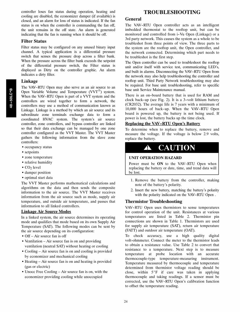
Replacing the VAV--RTU Open’s Battery 24. . . . . . . . . . . . . .
Thermistor Troubleshooting 24. . . . . . . . . . . . . . . . . . . . . . . . .
Software Version 25. . . . . . . . . . . . . . . . . . . . . . . . . . . . . . . . . .
Communication LED’s 25. . . . . . . . . . . . . . . . . . . . . . . . . . . . .
Alarms 28. . . . . . . . . . . . . . . . . . . . . . . . . . . . . . . . . . . . . . . . . .
Performance 30. . . . . . . . . . . . . . . . . . . . . . . . . . . . . . . . . . . . . .
APPENDIX A -- USER INTERFACE MENUS 32. . . . . . . . . . . .
APPENDIX B -- VAV ZONE AIRSIDE CONFIGURATION 40. . .
APPENDIX C -- VAV ZONE CONTROLLER --SUBMITTAL EXAMPLE 41. . . . . . . . . . . . . . .
APPENDIX D -- BACnetR POINTS LIST 44. . . . . . . . . . . . . . . .
APPENDIX E -- EQUIPMENT TOUCHNAVIGATION SCREENS 46. . . . . . . . . . . . . .
VAV--RTU OPEN START--UP SHEET 49. . . . . . . . . . . . . . . . . .
This document is to be used in conjunction with thefollowing Carrier Corporation manuals:S Equipment Touch Installation & Setup Guide
S Terminal Controller Installation & Setup Guide
S MS/TP Networking and Wiring Installation Guide

2
SAFETY CONSIDERATIONSInstallation and servicing of air-conditioning equipmentcan be hazardous due to system pressure and electricalcomponents. Only trained and qualified service personnelshould install, repair, or service air-conditioningequipment. Untrained personnel can perform the basicmaintenance functions of replacing filters. Trained servicepersonnel should perform all other operations.When working on air-conditioning equipment, observeprecautions in the literature, tags and labels attached tothe unit, and other safety precautions that may apply.Follow all safety codes. Wear safety glasses and workgloves. Have fire extinguisher available. Read theseinstructions thoroughly and follow all warnings orcautions attached to the unit. Consult local building codesand National Electrical Code (NEC) for specialrequirements.Recognize safety information. This is the safety--alert
symbol . When you see this symbol on the unit and ininstructions or manuals, be alert to the potential forpersonal injury.Understand the signal words DANGER, WARNING, andCAUTION. These words are used with the safety--alertsymbol. DANGER identifies the most serious hazardswhich will result in severe personal injury or death.WARNING signifies a hazard which could result inpersonal injury or death. CAUTION is used to identifyunsafe practices which may result in minor personalinjury or product and property damage. NOTE is used tohighlight suggestions which will result in enhancedinstallation, reliability, or operation.
ELECTRICAL SHOCK HAZARD
Failure to follow this warning could result in personalinjury or death.
Disconnect all power to the unit before performingmaintenance or service. Unit may automatically startif power is connected.
! WARNING
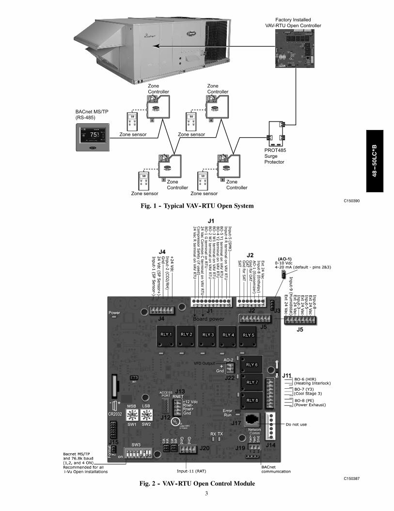
GENERALThe VAV--RTU Open controller is an integratedcomponent of the Variable Air Volume (VAV) Carrierrooftop unit system (see Fig. 1). Its internal applicationprogramming provides optimum performance and energyefficiency. VAV--RTU Open enables the unit to operatewith Carrier’s i--VuR Open network with i--Vu VAV zonecontrollers and monitored by Third Party BACnetR
Building Automation System (BAS). On--board DIPswitches allow you to select your baud rate. (See Fig. 2.)Carrier’s i--VuR user interface Equipment Touch orSystem Touch and the Field Assistant technician tool canbe used with the VAV--RTU Open controller. Access isavailable via a 5--pin J12 access port or Rnetcommunication network. Carrier’s System Touch interfacecan be used to configure the VAV rooftop and air terminalcontrollers when connected to the BACnet MS/TPnetwork.
SENSOR/ACCESSORYINSTALLATION
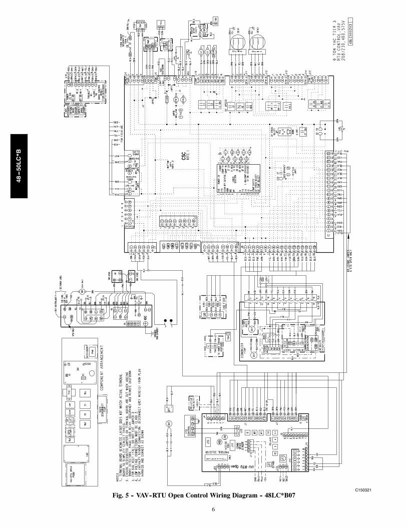
There are a variety of sensors and accessories availablefor the VAV--RTU Open and VAV zones. Some of thesecan be factory or field installed, while others are onlyfield installable. The VAV--RTU Open controller requiresconnection to the building zoning VAV system. All fieldcontrol wiring that connects to the VAV--RTU Open mustbe routed through the raceway built into the corner post ofthe unit or secured to the unit control box with electricalconduit. The unit raceway provides the UL requiredclearance between high and low-voltage wiring. Pass thecontrol wires through the hole provided in the corner post,then feed the wires thorough the raceway to theVAV--RTU Open. Connect the wires to the removablePhoenix connectors and then reconnect the connectors tothe board. See Fig. 2 and Table 1 for board connectionsand Fig. 5 through Fig. 10 for Typical Factory VAV--RTUOpen wiring.IMPORTANT: Refer to the specific sensor or accessoryinstructions for its proper installation and for rooftop unitinstallation refer to base unit installation instructions andthe unit’s wiring diagrams.
ELECTRICAL SHOCK HAZARD
Failure to follow this warning could result in personalinjury, death and/or equipment damage.
Disconnect electrical power and use lock--out tagsbefore wiring the VAV--RTU Open controller.
! WARNING
48---50LC*B
3
Factory InstalledVAV-RTU Open Controller
ZoneController
ZoneController
ZoneController
ZoneController
Zone sensorZone sensor
Zone sensorZone sensor
BACnet MS/TP(RS-485)
PROT485SurgeProtector
C150390Fig. 1 -- Typical VAV--RTU Open System
C150387Fig. 2 -- VAV--RTU Open Control Module
48---50LC*B

4
01
345
2
789 6
01
345
2
789 6
HW
V/A
CT
Gnd
AnalogOutput
Gnd
T55
(Opt
)
RH
/CO
2G
nd
S AT
Gnd
REM
OTE
n/a
Gnd
Rne
t +
Rne
t -
+12V
R n e tBACnet Power
On4321
-+
BattCR2032 10's
1's
ThermistorT55 (Opt)
RH/CO2
Factory Defaults
Rnet
MSTP
Class 2Output
24V Max,1A Max
Conductors Only
Class 2
Use Copper26Vdc, 0.1A, 3W
14VA, 0.58A24Vac, 50-60 Hz
This product was designedCAUTION:
to be mounted inside thebuilding envelope.Warrantyvoided if mounted outside.
Interconnect the Outputs ofDifferent Class 2 Circuits.
To ReduceThe Risk of Fireor Electric Shock, Do Not
CAUTION:
BACnet ®AO: 0-10 Vdc
5mA Max
LocalAccess
Short pins
Enable SAT
Enable SAT and REMOTE
CW CCW
Motor
Error
Run
Power
0-5Vdc
Made in USA
InputsTxRx
MSTP Baud
76.8k38.4k19.2k9600
Damper release button inside
TYPE: 002101E143900
88FO
Enclosed EnergyManagement Equipment
R
Net
+
Net
-
Shie
ld
Gro
und
24V
ac
Rnet+
Sense+12VRnet-
GndPow
er fo
r B.O
.sBU
S
HE
AT1
BT48
5
VAV ZoneSingle Duct
(OPN-VAVB1)
High
Low
Flow
(with filter)
C150388Fig. 3 -- VAV Zone Single Duct Controller
01
345
2
789 6
01
345
2
789 6
HW
V/A
CT
Gnd
AnalogOutput
Gnd
T55
(Opt
)
RH
/CO
2G
nd
S AT
Gnd
REM
OTE
n/a
Gnd
Rne
t +
Rne
t -
+12V
R n e tBACnet Power
On4321
-+
BattCR2032 10's
1's
ThermistorT55 (Opt)
RH/CO2
Factory Defaults
Rnet
MSTP
OutputsClass 224V Max,1A Max
Conductors Only
Class 2
Use Copper26Vdc, 0.1A, 3W
14VA, 0.58A24Vac, 50-60 Hz
This product was designedCAUTION:
to be mounted inside thebuilding envelope.Warrantyvoided if mounted outside.
Interconnect the Outputs ofDifferent Class 2 Circuits.
To ReduceThe Risk of Fireor Electric Shock, Do Not
CAUTION:
BACnet ®AO: 0-10 Vdc
5mA Max
LocalAccess
Short pins
Enable SAT
Enable SAT and REMOTE
CW CCW
Motor
Error
Run
Power
0-5Vdc
Made in USA
InputsTxRx
MSTP Baud
76.8k38.4k19.2k9600
Damper release button inside
TYPE: 002101E143900
88FO
Enclosed EnergyManagement Equipment
R
Net
+
Net
-
Shie
ld
Gro
und
24V
ac
Rnet+
Sense+12VRnet-
Gnd
FAN
/
Pow
er fo
r B.O
.sBU
S
HE
AT1
HE
AT2
HEA
T3
BT48
5
VAV ZoneFan Terminal
(OPN-VAVB3)
High
Low
Flow
(with filter)
C150389Fig. 4 -- VAV Zone Fan Terminal Controller
48---50LC*B
5
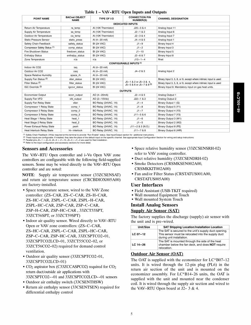
Table 1 – VAV--RTU Open Inputs and Outputs
POINT NAME BACnet OBJECTNAME TYPE OF I/O CONNECTION PIN
NUMBER(S) CHANNEL DESIGNATION
DEDICATED INPUTSReturn Air Temperature ra_temp AI (10K Thermistor) J20---3 & 4 Analog Input 11
Supply Air Temperature sa_temp AI (10K Thermistor) J2---1 & 2 Analog Input 6
Outdoor Air Temperature oa_temp AI (10K Thermistor) J2---3 & 4 Analog Input 7
Static Pressure Sensor static_press AI (4---20 mA) J4---4 & 5 Analog Input 1
Safety Chain Feedback safety_status BI (24 VAC) J1---9 Binary Input 4
Compressor Safety Status (1) comp_status BI (24 VAC) J1---2 Binary Input 3
Fire Shutdown Status firedown_status BI (24 VAC) J1---10 Binary Input 5
Enthalpy Status enthalpy_status BI (24 VAC) J2---6 & 7 Binary Input 8
Zone Temperature n/a n/a J13---1---4 Rnet
CONFIGURABLE INPUTS (4)
Indoor Air CO2 iaq AI (4---20 mA)J4---2 & 3 Analog Input 2Outdoor Air CO2 oaq AI (4---20 mA)
Space Relative Humidity space_rh AI (4---20 mA)
Supply Fan Status (2) sfan_status BI (24 VAC)J5---1 & 2 or J5---3 & 4,J5---5 & 6 or J5---7 & 8 (3)
Binary Input 3, 5, 8, or 9, except where intrinsic input is used
Filter Status (2) filter_status BI (24 VAC) Binary Input 3, 5, 8, or 9, except where intrinsic input is used
IGC Override (2) igcovr_status BI (24 VAC) Binary Input 9. Mandatory input on gas heat units.
OUTPUTSEconomizer Output econ_output AO (4---20mA) J2---4 & 5 Analog Output 1
Supply Fan VFD vfd_output AO (2---10Vdc) J22---1 & 2 Analog Output 2
Supply Fan Relay State sfan BO Relay (24VAC, 1A) J1---4 Binary Output 1 (G)
Compressor 1 Relay State comp_1 BO Relay (24VAC, 1A) J1---8 Binary Output 5 (Y1)
Compressor 2 Relay State comp_2 BO Relay (24VAC, 1A) J1---7 Binary Output 4 (Y2)
Compressor 3 Relay State comp_3 BO Relay (24VAC, 1A) J11---5 & 6 Binary Output 7 (Y3)
Heat Stage 1 Relay State heat_1 BO Relay (24VAC, 1A) J1---6 Binary Output 3 (W1)
Heat Stage 2 Relay State heat_2 BO Relay (24VAC, 1A) J1---5 Binary Output 2 (W2)
Power Exhaust Relay State pexh BO Relay (24VAC, 1A) J11---2 & 3 (N.O.) Binary Output 8 (PE)
Heat Interlock Relay State ht--- interlock BO Relay (24VAC, 1A) J11---7 & 8 Binary Output 6 (HIR)(1) Safety Chain Feedback: 24Vac required at this terminal to provide “Run Enable” status. See Input/Output section for additional instructions.(2) These inputs are configurable. If installed, they take the place of the default input on the specific channel. See appropriate Input Configuration Section for wiring and setup instructions.(3) Parallel pins J5---1 = J2---6, J5---3 = J1---10, J5---5 = J1---2 are used for filed installation.(4) Refer to the input configuration and accessory sections for more detail.
Sensors and AccessoriesThe VAV--RTU Open controller and i--Vu Open VAV zonecontrollers are configurable with the following field-suppliedsensors. Some may be wired directly to the VAV--RTU Opencontroller and are noted:NOTE: Supply air temperature sensor (33ZCSENSAT)and return air temperature sensor (CRCBDIOX005A00)are factory-installed.S Space temperature sensor, wired to the VAV Zone
controller: (ZS--CAR, ZS--C--CAR, ZS--H--CAR,ZS--HC--CAR, ZSPL--C--CAR, ZSPL--H--CAR,ZSPL--HC--CAR, ZSP--CAR, ZSP--C--CAR,ZSP--H--CAR, ZSP--HC--CAR , 33ZCT55SPT,33ZCT56SPT, or 33ZCT59SPT)S Indoor air quality sensor. Wired directly to VAV--RTU
Open or VAV zone controllers: (ZS--C--CAR,ZS--HC--CAR, ZSPL--C--CAR, ZSPL--HC--CAR,ZSP--C--CAR, ZSP--HC--CAR, 33ZCSPTCO2--01,33ZCSPTCO2LCD--01, 33ZCT55CO2--02, or33ZCT56CO2--02) required for demand controlventilation.S Outdoor air quality sensor (33ZCSPTCO2--01,
33ZCSPTCO2LCD--01)S CO2 aspirator box (C33ZCCASPCO2) required for CO2
return duct/outside air applications with33ZCSPTCO2----01 and 33ZCSPTCO2LCD----01 sensorsS Outdoor air enthalpy switch (33CSENTHSW)S Return air enthalpy sensor (33CSENTSEN) required for
differential enthalpy control
S Space relative humidity sensor (33ZCSENSRH-02)refer to VAV zoning controller.S Duct relative humidity (33ZCSENDRH-02)S Smoke Detectors (CRSMKSEN002A00,
CRSMKKIT002A00)S Fan and/or Filter Status (CRSTATUS001A00,
CRSTATUS005A00)
User InterfacesS Field Assistant (USB-TKIT required)S Wall mounted Equipment TouchS Wall mounted System Touch
Install Analog SensorsSupply Air Sensor (SAT)The factory supplies the discharge (supply) air sensor withthe unit and is pre--wired.
Unit/Size SAT Shipping Location/Installation Location
LC 07---12The SAT is secured to the unit’s supply duct opening.This sensor must be relocated into the supply ductduring unit installation.
LC 14---26The SAT is mounted through the side of the heatchamber below the fan deck, and does NOT requirerelocation.
Outdoor Air Sensor (OAT)The OAT is supplied with the economizer for LC*B07--12units. It is wired through the 12-pin plug (PL6) in thereturn air section of the unit and is mounted on theeconomizer assembly. For LC*B14--26 units, the OAT issupplied with the unit and mounted near the condensercoil. It is wired through the supply air section and wired tothe VAV--RTU Open board at J2-- 3 & 4.
48---50LC*B
6
C150321Fig. 5 -- VAV--RTU Open Control Wiring Diagram -- 48LC*B07
48---50LC*B

7
C150329Fig. 6 -- VAV--RTU Open Control Wiring Diagram -- 48LC*B08--12
48---50LC*B

8
C150330Fig. 7 -- VAV--RTU Open Control Wiring Diagram -- 48LC*B14--26
48---50LC*B

9
C150331Fig. 8 -- VAV--RTU Open Control Wiring Diagram -- 50LC*B07
48---50LC*B
10
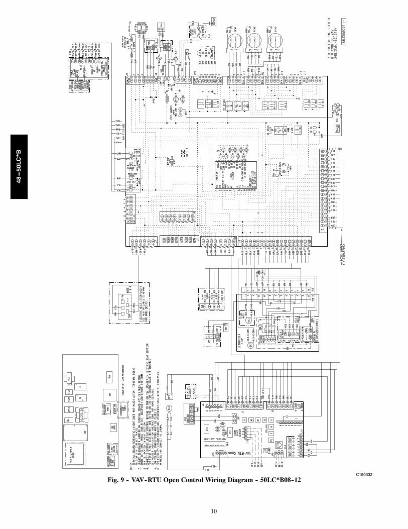
C150332Fig. 9 -- VAV--RTU Open Control Wiring Diagram -- 50LC*B08--12
48---50LC*B
11
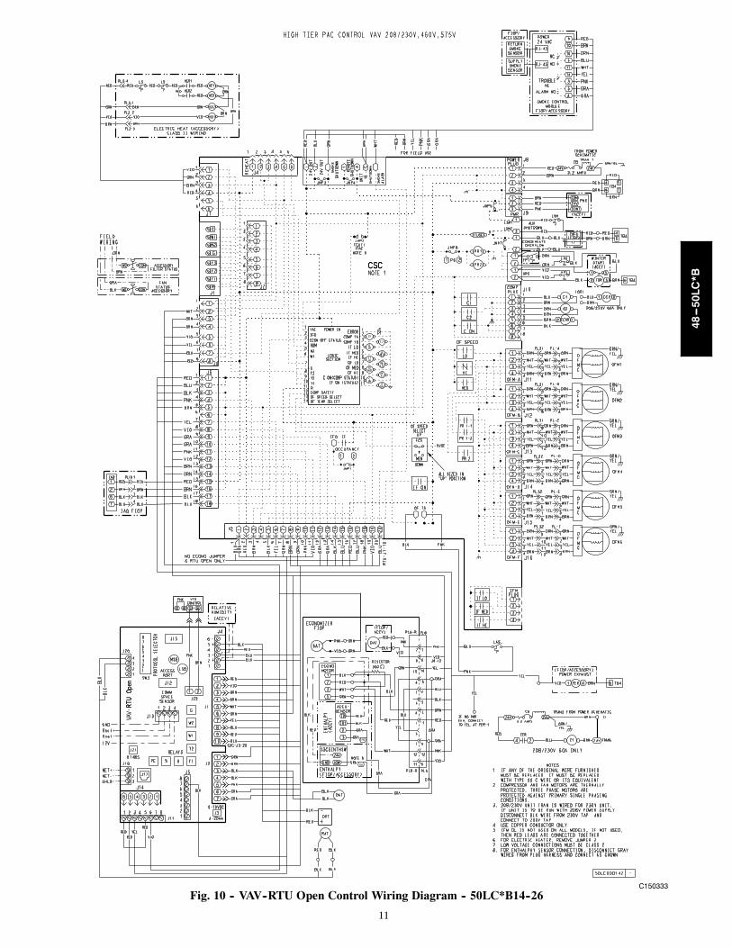
C150333Fig. 10 -- VAV--RTU Open Control Wiring Diagram -- 50LC*B14--26
48---50LC*B

12
Rnet Communicating Sensor WiringThe Rnet bus allows local communication with theVAV--RTU Open, including communicating sensors. TheRnet bus can support CO2, RH or a combination of CO2and RH wired directly to VAV--RTU Open for demandcontrol ventilation (CO2) and enables adjustment to anysupply air reset override when Supply Air Reset is enabled(RH control)..NOTE: Additional ZS sensors must be addressed. Usethe jumpers on the ZS sensor’s circuit board and refer tothe sensor installation instructions for addressing.
For Rnet wiring up to 500ft (152m), use 18 AWG 4conductor unshielded plenum rated cable. The VAV--RTUOpen’s J13-RNET connection has a 4 pin Phoenix connectorwired as described below, Fig. 11 shows sensor Rnet wiring.S RNET -- 1 = Signal ground (GND)S RNET -- 2 = Signal (Rnet+)S RNET -- 3 = Signal (Rnet--)S RNET -- 4 = Power (+12v)
C10820
Fig. 11 -- Typical Rnet Communication Sensor Wiring
CO2 Sensor(s) (IAQ and OAQ)The indoor air quality (IAQ) and outdoor air quality(OAQ) sensors monitor carbon dioxide (CO2) levels. Thisinformation is used to monitor the quality of air in termsof parts per million (PPM). The same sensor is used forinside, outside, and duct monitoring, except an aspiratorbox is required for outside and duct mounting. The CO2sensor is preset for a range of 0 to 2000 ppm and a linearmA output of 4 to 20. The rooftop unit may have a factoryinstalled CO2 sensor on the side of the economizer
assembly in the return air section of the unit and ispre-wired and pre-configured at the factory. For fieldinstalled sensors, a field supplied transformer must beused to power the sensor. Refer to the instructionssupplied with the CO2 sensor for electrical requirementsand terminal locations. VAV--RTU Open configurationsmust be changed after adding a CO2 sensor. See belowand Fig. 5 through Fig. 10 for typical CO2 sensor wiring.S J4--2 or J4--5 = 4--20mA signal inputS J4--3 or J4--6 = signal common
NOTE: The factory used J4-2&3 for CO2 (IAQ) sensorinputs.
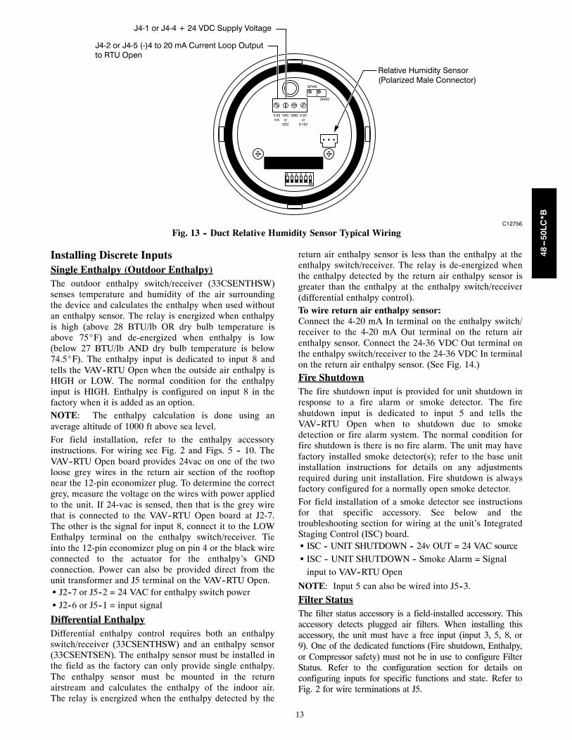
Relative Humidity Sensors (Space or DuctMounted)The accessory space humidity sensor or duct humiditysensor is used to measure the relative humidity of the airwithin the space or return air duct. For wiring distances upto 500 ft (152m), use a 3-conductor, 18 or 20 AWG shieldedcable. The shield must be removed from the sensor end ofthe cable and grounded at the unit end. The current looppower for the sensor is provided by the VAV--RTU Opencontroller as 24vdc. Refer to the instructions supplied withthe RH sensor for electrical requirements and terminallocations. VAV--RTU Open configurations must be changedafter adding a RH sensor. See below and Figs. 12 & 13 fortypical non--communicating RH sensor wiring.S J4--1 = 24vdc loop powerS J4--2 = 4--20mA signal input
SW2123456
ON
Io Vin Gnd Vo
MOUNTINGHOLES
WIRINGOPENING
a33-9141
Vin - J4 -1 or J4 -4 24VdcIo - J4 -2 or J4 -5 4 -20mA output
C07201
Fig. 12 -- Space Relative Humidity Sensor Typical Wiring
48---50LC*B
13
SPAN
ZERO
4-20mA
VACor
VDC
GND 0-5Vor
0-10V
123456
ON
J4-1 or J4-4 + 24 VDC Supply Voltage
J4-2 or J4-5 (-)4 to 20 mA Current Loop Outputto RTU Open
Relative Humidity Sensor(Polarized Male Connector)
C12756
Fig. 13 -- Duct Relative Humidity Sensor Typical Wiring
Installing Discrete InputsSingle Enthalpy (Outdoor Enthalpy)The outdoor enthalpy switch/receiver (33CSENTHSW)senses temperature and humidity of the air surroundingthe device and calculates the enthalpy when used withoutan enthalpy sensor. The relay is energized when enthalpyis high (above 28 BTU/lb OR dry bulb temperature isabove 75_F) and de-energized when enthalpy is low(below 27 BTU/lb AND dry bulb temperature is below74.5_F). The enthalpy input is dedicated to input 8 andtells the VAV--RTU Open when the outside air enthalpy isHIGH or LOW. The normal condition for the enthalpyinput is HIGH. Enthalpy is configured on input 8 in thefactory when it is added as an option.NOTE: The enthalpy calculation is done using anaverage altitude of 1000 ft above sea level.
For field installation, refer to the enthalpy accessoryinstructions. For wiring see Fig. 2 and Figs. 5 -- 10. TheVAV--RTU Open board provides 24vac on one of the twoloose grey wires in the return air section of the rooftopnear the 12-pin economizer plug. To determine the correctgrey, measure the voltage on the wires with power appliedto the unit. If 24-vac is sensed, then that is the grey wirethat is connected to the VAV--RTU Open board at J2-7.The other is the signal for input 8, connect it to the LOWEnthalpy terminal on the enthalpy switch/receiver. Tieinto the 12-pin economizer plug on pin 4 or the black wireconnected to the actuator for the enthalpy’s GNDconnection. Power can also be provided direct from theunit transformer and J5 terminal on the VAV--RTU Open.S J2--7 or J5--2 = 24 VAC for enthalpy switch powerS J2--6 or J5--1 = input signal
Differential EnthalpyDifferential enthalpy control requires both an enthalpyswitch/receiver (33CSENTHSW) and an enthalpy sensor(33CSENTSEN). The enthalpy sensor must be installed inthe field as the factory can only provide single enthalpy.The enthalpy sensor must be mounted in the returnairstream and calculates the enthalpy of the indoor air.The relay is energized when the enthalpy detected by the
return air enthalpy sensor is less than the enthalpy at theenthalpy switch/receiver. The relay is de-energized whenthe enthalpy detected by the return air enthalpy sensor isgreater than the enthalpy at the enthalpy switch/receiver(differential enthalpy control).To wire return air enthalpy sensor:--MPConnect the 4-20 mA In terminal on the enthalpy switch/receiver to the 4-20 mA Out terminal on the return airenthalpy sensor. Connect the 24-36 VDC Out terminal onthe enthalpy switch/receiver to the 24-36 VDC In terminalon the return air enthalpy sensor. (See Fig. 14.)
Fire ShutdownThe fire shutdown input is provided for unit shutdown inresponse to a fire alarm or smoke detector. The fireshutdown input is dedicated to input 5 and tells theVAV--RTU Open when to shutdown due to smokedetection or fire alarm system. The normal condition forfire shutdown is there is no fire alarm. The unit may havefactory installed smoke detector(s); refer to the base unitinstallation instructions for details on any adjustmentsrequired during unit installation. Fire shutdown is alwaysfactory configured for a normally open smoke detector.For field installation of a smoke detector see instructionsfor that specific accessory. See below and thetroubleshooting section for wiring at the unit’s IntegratedStaging Control (ISC) board.S ISC -- UNIT SHUTDOWN -- 24v OUT = 24 VAC sourceS ISC -- UNIT SHUTDOWN -- Smoke Alarm = Signal
input to VAV--RTU Open
NOTE: Input 5 can also be wired into J5--3.
Filter StatusThe filter status accessory is a field-installed accessory. Thisaccessory detects plugged air filters. When installing thisaccessory, the unit must have a free input (input 3, 5, 8, or9). One of the dedicated functions (Fire shutdown, Enthalpy,or Compressor safety) must not be in use to configure FilterStatus. Refer to the configuration section for details onconfiguring inputs for specific functions and state. Refer toFig. 2 for wire terminations at J5.
48---50LC*B

14
C10821
Fig. 14 -- Enthalpy Switch and Sensor Wiring
Fan StatusThe fan status accessory is a field-installed accessory.This accessory detects when the indoor fan is moving air.When installing this accessory, the unit must have a freeinput (input 3, 5, 8, or 9). One of the dedicated functions(Fire shutdown or Enthalpy) must not be in use toconfigure Fan Status. Refer to the configuration sectionfor details on configuring inputs for specific functions andstate. Refer to Fig. 2 for wire terminations at J5.
IGC OverrideThe IGC Override input is factory--installed for 48LC gasheat units. This input provides an indication that the gasvalve is stuck open and the heat is still operating after anycall for heating has been dropped. This function requiresthe use of input 9. Any of the other dedicated functions(Fan Status, Filter Status, Remote Occupancy, or DoorContact) will not be in use if IGC Override is configured.Refer to the configuration section for details onconfiguring inputs for specific functions and state. Referto Fig. 5 for wire terminations.
Communication Wiring --GeneralProtocols are the communication languages spoken bycontrol devices. The main purpose of a protocol is tocommunicate information in the most efficient methodpossible. Different protocols exist to provide differentkinds of information for different applications. In the BASapplication, many different protocols are used, dependingon manufacturer. Protocols do not change the function ofa controller; just make the front end user different.The VAV--RTU Open is set to communicate onBACnetRMS/TP. Switch 3 (SW3) on the board is used toset protocol and baud rate. Switches 1 and 2 (SW1 andSW2) are used to set the board’s network address. See Fig.16 and 17 for protocol switch settings and addressswitches. For network wiring reference refer to MS/TPNetworking and Wiring Installation Guide.NOTE: Power must be cycled after changing the SW1--3switch settings.
BACnetR MS/TPBACnet Master Slave/Token Passing (MS/TP) is used forcommunicating BACnet over a sub--network ofBACnet--only controllers. This is the default Carriercommunications protocol. Each VAV--RTU Open moduleacts as an MS/TP Master. The speed of an MS/TP networkcan range from 9600 to 76.8K baud. Physical Addressescan be set from 01 to 99.Wiring BACnet MS/TP network for VAV SystemThe VAV Open Control System uses linkage to exchangedata between the zone terminals and their air source toform a coordinated HVAC system. The system’s air sourcecontroller and zone controllers are linked so that their dataexchange can be managed by one zone controllerconfigured as the VAV Master.A VAV Master can have a maximum of 63 slave zonecontrollers reporting to it. An MS/TP network is limited toa maximum of 60 controllers, but a VAV Master can havecontrollers from other networks as slaves.A linked VAV system can be as simple as a single MS/TPnetwork with a VAV Master and slaves, or it can be ascomplex as multiple MS/TP networks with VAVsub--masters and slaves on other networks. See thefollowing example and Appendix B for configuringlinkage in VAV zone controllers.EXAMPLE: A simple network. The VAV Masterexchanges data between the slave controllers and theAHU controller. The linked controllers on an MS/TPnetwork must be sequentially addressed, and the VAVMaster must have the highest address.
Address Network #:16116
Slaves
12
34
56
78
VAVMaster
RTU
C150391
Fig. 15 -- Example -- Simple Network
i--VuR Building Automation Systemi--Vu is a Carrier front-end and Building Automation System(BAS). It is a web based network system that uses a nativeBACnet over MS/TP communication protocol. The speed ofthe network can range from 9600 to 76,800 baud. Refer toi--Vu literature for more information on i--Vu.
48---50LC*B

15
SW3 Protocol Selection
PROTOCOL DS8 DS7 DS6 DS5 DS4 DS3 DS2 DS1BACnetRMS/TP(Master) Unused OFF OFF OFF ON OFF Select Baud Select Baud
NOTE:DS = Dip SwitchBACnet MS/TP SW3 example shown
Baud Rate Selections
BAUD RATE DS2 DS19600 OFF OFF19,200 ON OFF38,400 OFF ON76,800 ON ON
C07166
Fig. 16 -- VAV--RTU Open SW3 Dip Switch Settings
C10815
Fig. 17 -- VAV--RTU Open Address Switches
Shield
C150411
Fig. 18 -- Network WiringLocal AccessWall Mounted System TouchThe System Touch (SYT1--4--CAR) is a wall mountedinterface used to connect to the VAV--RTU Open or VAVZone to access the control information, read sensor values,and maintenance. This is an accessory interface that does notcome with the VAV--RTU Open controller. You wire theSystem Touch to the VAV--RTU Open or VAV Zone BACnetMS/TP network wiring connection. There are 2 passwordprotected levels in the display (User and Admin). See theEquipment Touch Installation and Setup Guide for moreinformation. See Appendix A for navigation and screencontent.
Field AssistantField Assistant is a computer program included with thepurchase of the Tech Tool Kit (USB-TKIT). This is a fieldTech Tool to set-up, service, or download applicationsoftware to the VAV--RTU Open controller and includes aUSB Link Cable. The link cable connects a USB port tothe J12 local access port. The Field Assistant’s menustructure is similar and functions the same as i--VuR. SeeFig. 19.
Connect tocomputer’sUSB port
Connect tothe Local
Access portUSB Link Kit VAV-RTU Open
AccessPort
J12
P1 P1
P5 P5LOCAL
ACCESSPORT
GN
D
GN
D
*Thermm
A
*Thermm
A
UI-10UI-11
SW3
on
CO
MM
OP
TIO
N
CR2032
+-
SW1 SW2
MSB LSB
TXRX
+12 DVCRnet-Rnet+GND
RNET
J12
J13
J15J20
C150394
Fig. 19 -- PC Running Field Assistant
48---50LC*B
16
START--UPIMPORTANT: Follow the base unit’s start-up sequencedocumented in its specific instructions. Use the base unit’sstart-up check list when performing the start-up. At theend of this manual there is an additional VAV--RTU OpenStart-up Sheet to be completed and included with the baseunit check list.
Besides the base unit start-up, there are a few steps to take toproperly start-up the controls. VAV--RTU Open’s ServiceTest function should be used to assist in the base unitstart-up and also allows verification of output operation.Controller configuration is also part of start-up. This isespecially important when field accessories have been addedto the unit. The factory pre-configures options installed atthe factory. There may also be additional installation steps orinspection required during the start-up process.
VAV--RTU Open System StartupBefore system test mode is activated the VAV Zoneterminals and VAV--RTU Open are required to beprogrammed to meet the application. Reference the terminalcontroller installation and start--up guide for configurationfor specific terminals. (OPN--VAVB3 / OPN--VAVB1) andthis manual for VAV--RTU Open.Proper addressing and programming for the units can befound in referenced manuals prior to setting up system.
Step 1 —Set up the terminals minimum and maximum airflowsetpoints so that sufficient system minimum airflow ismaintained in both heating and cooling modes. Refer tothe Product Data for the specific rooftop equipment todetermine those minimum values.
Step 2 —Refer to product data for the VAV RTU, verify the sum ofthe minimum heat airflow setpoints for all the air terminalare 80–100% of the minimum heating airflow requirementfor the unit.
Step 3 —Refer to product data for the VAV RTU, verify the sum ofthe maximum cool cfm setpoints are equal to or greaterthan the units max airflow.
Step 4 —Now the unit can be put in service test mode and the fantest used to set minimum VFD speed. The fan will startwhen the fan test is set to enable. The test runs the fan atminimum speed (default 25%) as configured in the VAVRTU controller. During this time all terminals will beopen 70%.The minimum VFD output is set to a factory default of25% which may be increased or decreased as required sothat measured value of static pressure read will beapproximately 0.07--0.1”wg.
Step 5 —Final Test & Balance can be performed with Test andBalance software for system available from your localCarrier office. The USB adaptor and cable (USB--L) willalso be required..
Additional Installation/InspectionInspect the field installed accessories for properinstallation, making note of which ones do or do notrequire configuration changes. Inspect the VAV--RTUOpen’s Alarms for initial insight to any potential issues.See troubleshooting section for alarms. Inspect the SATsensor for relocation as intended during installation.Inspect special wiring as directed below.
Power Exhaust Relay PowerThe relay used by the VAV--RTU Open board to controlpower exhaust is a dry contact which means it does nothave 24vac. This 24vac must be connected to the relay toallow it operate the power exhaust relay in the PEaccessory. A 24vac source should be provided to the J11-2pin on the VAV--RTU Open. This can be provided by theunit’s transformer from various sources. The “R” terminalon the unit’s Integrated Staging Control (ISC) board is alogical source.NOTE: Factory installed power exhaust comespre--configured and does not require routing 24vac asdescribed above. This factory installed option is onlyavailable on the following vertical air flow units:48/50LC*B 14--26.
Service TestThe Service Test function can be used to verify properoperation of compressors, heating stages, indoor fan,power exhaust fans and economizer. Use of Service Test isrecommended at initial system start up and duringtroubleshooting. See Appendix A for Service Test Modetable.Service Test mode has the following changes from normaloperation:S Outdoor air temperature limits for cooling circuits,
economizer, and heating are ignored.S Normal compressor time guards and other staging
delays are ignored.
S The status of Alarms (except Fire and Safety chain) isignored, but all alerts and alarms are still broadcastedon the network.
Service Test can be turned ON/OFF from Field Assistant,from the network, or from the Equipment or SystemTouch. Once turned ON, other entries may be made withthe display or through the network. To turn Service Teston, change the value of Test Mode to ON, to turn ServiceTest off, change the value of Test Mode to OFF.Service Test allows testing of each controller output.Binary Service Test functions are on when the DefaultValue is set to Enable and off when set to Disable.The output of the Analog Service Test is controlled bypercentage (0--100%) entered into the Default Value.It is recommended to return every Service Test variable toDisable or 0.00 after testing each function (unless that testvariable must be active to test a subsequent function. Asin Compressor 2 Test).All outputs return to normal when Service Test is set toDisable. In addition, Service Test also returns to Disableafter 1 hour.
48---50LC*B

17
Fan TestThis point allows the board’s fan output to be manuallyturned On (Enable) and Off (Disable). Other test pointsthat require the fan for operation will automatically turnthe fan on and this point will still show “Disable.” Fan testcan operate simultaneously with other Service Test Points.The fan test will operate the unit’s fan at minimum VFDoutput speed.
Compressor 1 and Compressor 2 TestThe compressor test points are used to change outputstatus for the individual compressors. Compressor startsare not staggered. The fan and heating service test outputsare reset to “Disable” for the compressor service tests.Compressor Tests can be enabled separately for Stage 1 or2 or enabled in combination for Stage 3. The Indoor fanand outdoor fans are controlled normally to maintainproper unit operation. All normal cooling alarms andalerts are functional.
Heat 1 and Heat 2 TestThe heat test points are used to change output status forthe individual heat stages, gas or electric. The fans andcooling service test outputs are reset to “Disable” for theheat service tests. Indoor and outdoor fans are controllednormally to maintain proper unit operation. All normalheating alarms and alerts are functional.
Power Exhaust TestThis point allows the board’s power exhaust (PE) outputto be manually turned On (Enable) and Off (Disable).Power Exhaust test can operate simultaneously with otherService Test Points.
Economizer TestThis point allows the board’s economizer output to bemanually controlled from 0 to 100 % Open. Economizer testcan operate simultaneously with other Service Test Points.
VFD Speed TestThis point activates the board’s 0--10vdc analog outputthat controls the unit’s supply fan VFD speed.NOTE: Service Test Mode does not timeout. Be sure toturn off test mode or cycle power to the RTU to return tonormal operation.
ConfigurationThe VAV--RTU Open controller’s configuration pointseffect the unit’s inputs and operation. Review andunderstand the meaning and purpose of each configurationpoint before changing it from the factory default value.Use the VAV--RTU Open Start-up Sheet duringconfiguration; fill in changed values if changed fromfactory default. There are three main configurationsmenus: SETPOINT, UNIT CONFIGURATION, SERVICEand LINKAGE.Each configuration point is described below under itsaccording menu. See Appendix A for menu structure.
SetpointSupply Air Setpoint -- The user--defined base setpoint forSupply Air while in the Cooling mode.
Range = 45 - 75_FDefault = 53_F
Static Pressure Setpoint – The base setpoint for supplyduct static pressure to be maintained at the static pressuresensor, which is located approximately 2/3 of the waydown the supply duct.
Range = 0.25 to 2.25 Iwc Default = 0.5 IwcSupply Air Tempering Setpoint – The temperaturedefined to control supply air when Outside Air Temp isbelow Supply Air Temp Low limit and unit is operating inFan Only or IAQ Override mode.
Range = 40 - 75_F Default = 48_FOcc Relative Humidity Setpoint – The setpoint used todetermine when any supply air reset, if previouslycalculated, should not be used. This will cause the supply airto be controlled at a temperature closer to the configuredSAT setpoint when a high humidity condition exists.
Range = 0 to the Unocc RH control setpointDefault 60% RH
DCV Max Ctrl Setpoint – The difference between indoorand outdoor CO2 level which results in maximumventilation damper position. This value is transmittedthrough linkage from the VAV zones.
Range = 0-9999ppm Default = 110ppmPower Exhaust Setpoint – The outside air damperposition at which the controller energizes the PowerExhaust relay.
Range = Open Default = OpenNOTE: This setpoint is automatically adjusted in order tomaintain proper building pressure. The actual calculatedvalue, Calculated PE Setpoint, is shown inMAINTENANCE.
NOTE: This point is only used when ContinuousOccupied Exhaust = NO
Unit ConfigurationFan Mode – Sets the operation of the indoor fan when notin cooling or heating mode. Refer to fan operation fordetails on each operation.
Range = Auto, Continuous, or Always OnDefault = Continuous
Power Fail Restart Delay -- Sets how long the controllerdelays normal operation after the power is restored.Typically used to prevent excessive demand whenrecovering from a power failure
Range = 0 - 30 sec Default = 5 secFan Off Delay – The number of seconds that the fancontinues to run after heating or cooling has ended.
Range = 5 -- 120 secDefault = 90 sec
Occupied Heating – Once a morning warmup cycle iscomplete, Occupied Heating allows the unit to return toheating, if needed. If Disable is selected, the unit will notreturn to heating until the next occupancy cycle.
Range = Disable/EnableDefault = Disable
Supply Air Temp Reset – Allows the Supply AirTemperature Setpoint to be reset upward based on theamount the controlling zone temperature has fallen belowthe cooling setpoint.
Range = Disable/EnableDefault = Disable
48---50LC*B

18
Reset Ratio – The amount of reset calculated per degreeas the controlling zone temperature falls below thecooling setpoint.
Range = 0 -- 10 Default = 3Reset Maximum Limit – The highest value in degrees ofreset allowed when calculating the Supply Air Temp Reset.
Range = 0 - 25_F Default = 10_FHumidity Override – Allows a reduction of thecalculated Supply Air Temp Reset as the Space RelativeHumidity approaches the Occ Relative Humidity Setpoint.
Range = Disable/EnableDefault = Disable
Minimum Cooling SAT – In cooling mode, the coolingoutputs are controlled so that the supply air temperaturedoes not drop below this value. The Minimum CoolingSAT is upper--limited by the calculated Supply Air TempClg. Setpoint minus 5_.
Range = 45 - 75_F Default = 45_FMaximum Heating SAT – In heating mode, the heatingoutputs are controlled so the supply air temperature does notrise above this value. The Maximum Heating SAT isupper--limited by the calculated Automatic Max SAT LimitLearning algorithm.
Range = 90 - 150_F Default = 120_FVent Dmpr Pos / DCV Min Pos – The minimum outdoorair damper position maintained during occupied periods.
Range = 0 -- 100% open Default = 20% openLow Fan Econ Min Pos – The minimum outdoor airdamper position maintained during occupied periods whenthe fan is running at the minimum VFD speed.
Range = 0 -- 100% Default = 33%DCV Max Vent Damper Pos – The maximum outdoorair damper position allowed while DCV is active.
Range = 0 -- 75% open Default = 50% openStatic Pressure Reset Enable – Enables Static Pressuresetpoint reset, based on air terminal damper positionreceived via Linkage. When the air terminal maximumdamper is less than Minimum Damper Position, the unitinitiates static pressure reset by lowering the calculated staticpressure setpoint.
Range = Disable/Enable Default = EnableMaximum Damper Position – The trip point for themaximum air terminal damper position, received viaLinkage, that calculates a reduction in any previouslycalculated static pressure reset value. When any airterminal has a damper above the Maximum DamperPosition, the static pressure setpoint begins to increasetoward the configured Static Pressure Setpoint.
Range = 0 to 100% Open Default = 80% OpenMinimum Damper Position – The trip point for theminimum air terminal damper position, received viaLinkage, that calculates static pressure setpoint reset.When all air terminals have their damper below theMinimum Damper Position, the Current Static PressureSetpoint Reset value will increase, reducing the staticpressure setpoint.
Range = 0 to 100% Open Default = 50% OpenMaximum Reset – The maximum static pressure resetallowed.
Range = 0.05 to 2.50 Iwc Default = 0.25 Iwc
SP Reset Demand Level – Enables the System DemandLevel specified to lower the static pressure by the maxi-mum reset value, when active. Enabling is cumulative forthat level and higher levels with Cool Dmd Lvl 3 beingthe highest load shedding demand level.
Range = Not Active, Cool Dmd Lvl 1,Cool Dmd Lvl 2 Cool, Dmd Lvl 3
Default= Not ActiveSupply Fan Service Alarm Timer -- A Supply FanRuntime alarm is generated when the supply fan run hoursexceed this value. Set to 0 to disable.
Range = 0 to 9999 hr Default = 600 hrCompressor 1 Service Alarm Timer – A Compressor 1Runtime alarm is generated when the compressor 1 runhours exceed this value. Set to 0 to disable.
Range = 0 to 9999 hr Default = 0 hrCompressor 2 Service Alarm Timer -- A Compressor 2Runtime alarm is generated when the compressor 2 runhours exceed this value. Set to 0 to disable.
Range = 0 to 9999 hr Default = 0 hrFilter Service Alarm Timer -- The amount of time thefan will run before generating a Filter Alarm. Set to 0 todisable the alarm and reset accumulated fan hours.
Range = 0 to 9999 hr Default = 600 hrHeat 1 Service Alarm Timer -- A Heat 1 Runtime alarmis generated when the Heat Stage 1 run hours exceed thisvalue. Set to 0 to disable.
Range = 0 to 9999 hr Default = 0 hrHeat 2 Service Alarm Timer -- A Heat 2 Runtime alarmis generated when the Heat Stage 2 run hours exceed thisvalue. Set to 0 to disable.
Range = 0 to 9999 hr Default = 0 hrDoor Alarm Delay -- Determines the amount of delaybefore a door alarm is generated.
Range = 0 to 3600 seconds Default = 60 secondsCooling Lockout Temperature -- Cooling is inhibitedbelow this outdoor air temperature.
Range = --65 to 80_F Default = 45_FEconomizer High OAT Lockout Temp -- The outdoor airtemperature above which economizer cooling is inhibited.
Range = 55 to 80_F Default = 75_FHeating Lockout Temperature -- Heating is inhibitedabove this outdoor air temperature.
Range = 35 to 150_F Default = 65_FUnocc Free Cool -- Enables or disables the use of theeconomizer to provide unoccupied free cooling (NTFC).
Range = Disable/Enable Default = DisableMinimum Setpoint Separation -- The minimum amountof temperature separation between the heating and coolingsetpoints.
Range = 2 to 10_F Default = 5_F
InputsInput 2 Function – This input is an analog (4--20mA)input and can be configured to be one of four differentinputs: No Sensor, IAQ Sensor, OAQ Sensor, or Space RHSensor. Input 2 is wired to pin J4--1,2,3.
Software Default = No SensorFactory Default = IAQ Sensor with factory
installed CO2 sensor
48---50LC*B

19
NOTE: For Input 2, if using Carrier air quality sensors donot use 24Vdc from VAV--RTU Open board. External24Vdc power supply required.
Input 3 -- This input is a discrete input and can beconfigured to be one of four different functions: NoFunction, Compressor Safety, Fan Status, and FilterStatus. This input can also be configured to be either aNormally Open (N/O) or a Normally Closed (N/C) switch.Input 3 is factory wired to pin J1-2. Field accessories canbe wired to its parallel pin J5-5. You must also set Input 3Switch Configuration.
Software Default = No FunctionInput 5 -- This input is a discrete input and can beconfigured to be one of four different functions: NoFunction, Fire Shutdown, Fan Status, and Filter Status. Thisinput can also be configured to be either a Normally Open(N/O) or a Normally Closed (N/C) switch. Input 5 is factorywired to pin J1-10. Field accessories can be wired to itsparallel pin J5-3. You must also set Input 3 SwitchConfiguration.
Software Default = Fire Shutdown and N/CFactory Default = Fire Shutdown and N/O
Input 5 Switch Configuration -- The normal (de--energized)state for the set of contacts terminated at Input 5.
Range = NO/NC (normally open/normally closed)Default = NO
Input 8 -- This input is a discrete input and can beconfigured to be one of six different functions: NoFunction, Enthalpy Switch, Fan Status, and Filter Status.This input can also be configured to be either a NormallyOpen (N/O) or a Normally Closed (N/C) switch. Input 8 isfactory wired to pin J2-6. Field accessories can be wiredto its parallel pin J5-1.
Software Default= Enthalpy Switch and N/OFactory Default = No Function and N/O without
factory installed enthalpy sensorInput 8 Switch Configuration -- The normal (de--energized)state for the set of contacts terminated at Input 8.
Range = NO/NC (normally open/normally closed)Default = NO
Input 9 -- This input is a discrete input and can beconfigured to be one of seven different functions: NoFunction, Fan Status, and Filter Status, or IGC Override.This input can also be configured to be either a NormallyOpen (N/O) or a Normally Closed (N/C) switch. Input 9 isfactory and field wired to pin J5-7.
Factory Default = N/ONOTE: For 48LC*B 07--26 Units (gas heat units) thisdecision is automatically set to IGC Override and isfactory wired.
Input 9 Switch Configuration -- The normal (de--energized)state for the set of contacts terminated at Input 9.
Range = NO/NC (normally open/normally closed)Default = NO
ZS Sensor Type -- The type of local space temperaturesensor.
Range = ZS Base, ZS Plus, ZS ProDefault = None
Rnet Port -- input for communicating sensor orEquipment Touch Terminal J13 -- 1, 2, 3, 4
Range = SPT Sensor, ZS Sensor, orEquipment Touch
Default= None
Service ConfigurationCompressor Stages – The number of mechanical coolingstages. This decision is not configurable.
Default = Three stagesEconomizer Exists – Set to Yes at factory. This decisionis not configurable.
Default = YesVFD Input – Defines the electrical control signal used bythe Variable Frequency Drive’s (VFD) input.
Range = 0--10 Vdc, 2--10 VdcDefault = 2--10 Vdc
Max VFD Output – The maximum output signal thecontrol supplies to the VFD as a percentage of its range.The balancer can set this to adjust the unit’s maximumairflow.
Range = 15% to 100% Default = 100%Min VFD Output – The minimum output signal thecontrol supplies to the VFD as a percentage of its range.This must be set to ensure the unit’s minimum airflow.
Range = 15% to 100% Default = 25%Heat Type – The type of heating used by the unit.
Range = Electric/Gas Default = GasNumber of Heat Stages – The number heat stages.
Range = 1 / 2 /0 (no heating) Default = 2SA Tempering – Supply Air Tempering permits usingheating, if installed to temper OA while unit is in FanOnly or IAQ Override mode.
Range = Disable/Enable Default = DisableContinuous Occupied Exhaust – This point tells thecontroller when to run the power exhaust if equipped onthe unit.If set to YES, the power exhaust will be on all the timewhen in occupied mode and will be off when inunoccupied mode. If set to NO the power exhaust will becontrolled by the Power Exhaust Setpoint.
Range = YES/NO Default = NODCV Control -- Enables demand controlled ventilation(DCV) if valid CO2 sensor value is available and the unithas an economizer installed.
Range = Disable/EnableDefault = Disable
Indoor CO2 Sensor Value @min (ma) -- The CO2 valuethat corresponds to a 4mA input at the appropriate inputchannel.
Range = 0 to 9999 ppm Default = 0 ppmIndoor CO2 Sensor Value @max (ma) -- The CO2 valuethat corresponds to a 20mA input at the appropriate inputchannel.
Range = 0 to 9999 ppm Default = 2000 ppmOutdoor CO2 Sensor Value @min (ma) -- The CO2value that corresponds to a 4mA input at the appropriateinput channel.
Range = 0 to 9999 ppm Default = 0 ppm
48---50LC*B

20
Outdoor CO2 Sensor Value @max (ma) -- The CO2value that corresponds to a 20mA input at the appropriateinput channel.
Range = 0 to 9999 ppm Default = 2000 ppmNOTE: The indoor and outdoor min and max mA settingare used to set the linear curve of mA vs. PPM.
System Space Temperature -- The network spacetemperature value that the controller is using for control(if applicable).
Range = N/A Default = --999.0_FSystem Space RH -- The network relative humidity valuethat the controller is using for control (if applicable)
Range = N/A Default = --999.0%System Space AQ -- The network indoor air quality (CO2)value that the controller is using for control (if applicable)
Range = N/A Default = --999.0 PPMSystem Cool Demand Level -- The system cool demandlevel being received over the network
Range = N/A Default = 0--3System Heat Demand Level -- The system heat demandlevel being received over the network
Range = N/A Default = 0--3System Outdoor Air Temperature -- Allows the outdoor airtemperature value to be network readable when enabled.
Range = N/A Default = --999.0_FSystem Outdoor AQ -- Allows network readable value ofOAQ for calculation during differential OAQ CO2 levelsand IAQ CO2 levels to drive the IAQ control
Range = N/A Default = --999.0 PPMSystem Fire / Smoke -- Allows network readable fire/smokesignal to invoke shutdown action in the RTU
Range = N/A Default = OFF
OPERATIONThe VAV--RTU Open will control the compressors,economizer and heating outputs based on the spacetemperature inputs and setpoints received from the zoningmaster through Linkage. An optional CO2 IAQ sensormounted in the space can influence the economizerminimum position. The following sections describe theoperation for the functions of the VAV--RTU Open.
OccupancyOccupancy is the fundamental overall control of equipment.The unit can be in one of two states: Occupied orUnoccupied. These are usually referred to as periods becausethey represent periods of any given day. Before VAV--RTUOpen can operate specific functions of the equipment it isinstalled on, occupancy must be determined. Occupancyonly comes from the Linked zoning system.
Indoor (Supply) FanThe indoor fan can be configured to operate in threedifferent manors. The configuration point Fan Modedetermines how the fan will run. The fan will always bedisabled if a fire shutdown or safety chain alarm is active.A valid space temperature and supply air temperaturemust be available for the fan to operate. There is a unitstart delay in effect when the unit is transitioning fromunoccupied to occupied. The following describes specificfan operation based on the Fan Mode configuration value.
AutoWhen Fan Mode is set to Auto, VAV--RTU Open will cyclethe fan on and off based on the demand for heating, andcooling. There is a configurable fan off delay that is upheldbefore shutting the fan off after conditioning has ended.
ContinuousWhen Fan Mode is set to Continuous, VAV--RTU Openwill cycle the fan based on occupancy. The fan will runcontinuously whenever the unit is occupied and operate inthe auto mode during the unoccupied period.
Always OnWhen Fan Mode is set to Always On, VAV--RTU Openwill run the fan all the time regardless of occupancy ordemand.
Fan Off DelayA Fan Off Delay allows the supply fan to continueoperating after heating or cooling stops. If the followingalarms are active, the fan turns off immediately, regardlessof the occupancy state or demand:S Fire ShutdownS Safety ChainS Supply Air Temp Sensor alarm
The VAV--RTU Open does not include smoke--controlfunctions such as smoke--purge, zone--pressurization, orsmoke--ventilation.
Indoor (Supply) Fan StatusThe VAV--RTU Open has an optional Supply Fan Statusinput to provide proof of airflow. If this is enabled, thepoint will look for a contact change whenever the SupplyFan Relay is on. If it is not enabled then it will always bethe same state as the Supply Fan Relay. The cooling,economizer, heating, CO2 and power exhaust routines willuse this input point for fan status.
CoolingThe VAV--RTU Open’s application and configurationdetermines the specific cooling sequence. The VAV--RTUOpen controls 3 stages of mechanical cooling. Thenumber of stages is not configurable.The following conditions must be true for the coolingalgorithm to operate:S Cooling is required. (If occupied, the space temperature
is > occupied cooling setpoint if reset is disabled orspace temperature > occupied heating setpoint + 1_F(.5_C)] if reset is enabled. If unoccupied, spacetemperature is > unoccupied cooling setpoint).S Outdoor Air Temperature, if valid, is greater than the
Cooling Lockout Temperature setpoint
S The Supply Fan is onS The unit has a valid Supply Air Temperature inputS The unit has a valid Space Temperature inputS Heat mode is not active and the 5--minute time guard
between modes has expiredS Economizer cooling is unavailable, or if Economizer
cooling is active, the economizer is open > 90% for atleast 5 minutes, the OAT > [Supply Air Setpoint+ 5_F(2.7_C)], SAT > Supply Air Setpoint, and cooling
48---50LC*B

21
mode is active (SPT > CSP if reset is disabled or SPT >HSP +1 if reset is enabled).
The cooling relays are controlled by the Cooling ControlPID Loop and Cooling Capacity algorithm. They calculatethe desired number of stages needed to satisfy the supplyair temperature setpoint.When the cooling algorithm preconditions have been met,the compressors are energized in stages, as applicable.Anti--recycle timers are employed to protect theequipment from short--cycling. There are fixed 3 minuteminimum on--times, and 1 minute off--times for eachcompressor output.During compressor operation, the VAV--RTU Open willreduce the number of active stages to only one if therooftop supply air temperature falls below the Supply AirSetpoint. During mechanical cooling, should the SAT fallbelow the configured Minimum Cooling SAT value of45_F (7.2_C), the economizer will modulate more open tomaintain the minimum SAT. During integrated cooling,should the SAT fall below the configured MinimumCooling SAT value of 45_F (7.2_C), the economizer willmodulate more closed to maintain the minimum SAT. TheMinimum Cooling SAT is user configurable between 45_F(7.2_C) and 75_F (23.9_C)Compressor Service Alarm Timer functions are available(1 for each compressor). This function tracks the numberof compressor run hours and generates an alarm when theaccumulated runtime exceeds the threshold set by theadjustable compressor service alarm timers.
Supply FanThe VAV--RTU Open supply fan is configured for VariableSpeed operation:S Fan speed is controlled to maintain the configured duct
static pressure setpoint.
The VAV--RTU Open supply fan may be configured for 1of 3 Fan Modes:S Auto -- The fan cycles on/off in conjunction with
heating or cooling.S Continuous -- The fan runs continuously during
occupancy and intermittently during unoccupiedperiods with heating and cooling.
S Always On -- The fan runs continuously regardless ofoccupancy or calls for heating and cooling.
Occupancy is determined by Linkage.A Fan Off Delay allows the supply fan to continueoperating after heating or cooling stops.If the following alarms are active, the fan turns offimmediately, regardless of the occupancy state or demand:S Fire ShutdownS Safety chainS SAT sensor alarmS SPT sensor alarms
The VAV--RTU Open does not include smoke--control func-tions such as a smoke--purge, zone--pressurization, orsmoke--ventilation. Each of these modes require a field--de-signed circuit to operate the following by local fine codes:S RTU supply fan
S RTU economizerS RTU power exhaust
The VAV--RTU Open many be configured to accept aSupply Fan Status input to provide proof the supply fan isoperating. When enabled, a loss or lack of fan status willstop heating and cooling operation.A supply Fan Alarm Service Timer function is availableto track the number of supply fan run hours and generatean alarm when the accumulated runtime exceeds the setthreshold.
EconomizerThe Economizer dampers are used to provide free coolingwhen the outside conditions are suitable and Indoor AirQuality, if optional CO2 sensor is installed.The following conditions must be true for economizeroperation:S Indoor Fan is on.S Enthalpy is Low if the Enthalpy input is enabled.S SAT reading is available.S OAT reading is available.S SPT reading is available.S OAT <= High OAT economizer lockout configuration
(default = 75).S OAT <= SPT
For LC VAV rooftop the VAV--RTU Open will determinethe required minimum economizer position (CalculatedMin Econ Pos) based on the fan’s actual operation speed.The minimum damper position can be overridden by theIAQ routine described later in this section.Since the VAV--RTU Open provides variable supplyairflow to the VAV system, as the supply airflow changes,the economizer minimum position is adjusted to provide aconstant amount of outdoor air. If the fan operates atmaximum speed, the economizer minimum position willbe set to the Vent Dmpr Pos / DCV Min Pos setpoint.When the fan operates at its lowest speed, the economizerminimum position will be set to the Low Fan Econ MinPos. For any fan speed between the minimum andmaximum speeds, the VAV--RTU control calculates aminimum economizer position by a linear interpolationbetween these two values. When cooling is required, if allpreceding conditions are true and the outdoor EnthalpyStatus is Low, the economizer PID loop modulates thedamper between the minimum position and 100% open tomaintain the Supply Air Setpoint.
During economizer operation, the economizer position isreduced as the SAT falls below the Supply Air setpoint --3_F (1.7_C), but never closes below the applicableminimum ventilation position. The Calculated Min EconPos used for control is displayed in the Maintenancesection.
VAV--RTU Open provides Fault Diagnostic and Detection(FDD) for economizer operation in compliance withCalifornia Title 24. The FDD logic will detect aneconomizer that fails to close, fails to open, stuck fullyopen, and fails to fully open. Each condition will cause anEconomizer Operation alarm to occur and the specificcondition will be displayed.
48---50LC*B
22
Enthalpy ControlYou may use an enthalpy switch to indicate the suitability ofoutdoor air for economizer cooling. You can use either anoutdoor air or differential enthalpy switch. A differentialenthalpy switch has a sensing device in both the outdoor andreturn air streams. A differential enthalpy switch indicateswhen outside air is more suitable to be used than the returnair and is available for economizer cooling. If no enthalpyswitch is configured, a network point (Object Name: oae) isavailable. This point is displayed in the i--Vu application andEquipment Touch as Enthalpy (BACnet).The sequence of operation for economizer cooling is thesame with or without an enthalpy switch, except that anenthalpy switch imposes one more validation on thesuitability of outside air for economizer cooling. AnEnthalpy Status that is High disables the economizer and theoutside air damper goes to its minimum position. AnEnthalpy Status that is Low enables the economizer if a callfor cooling exists and the remaining preconditions are met.
Space Air QualitySpace Air Quality (AQ) is controlled on rooftopequipment using the economizer. The Space AQ sequenceutilizes an air quality (CO2) sensor to monitor conditionswithin the occupied space. A CO2 sensor may beterminated at the VAV--RTU Open, or a subordinate zonecontroller, when part of a zoned system.When an outdoor air quality sensor is not installed, thealgorithm uses 400ppm as the fixed outdoor air CO2 level.The following conditions must be true for the Space AQalgorithm to operate:S The system is occupiedS The supply fan has been operating for at least 30 secondsS The Space AQ sensor has a valid reading
As the air quality in the space decreases (Space AQ CO2value increases), the minimum position of the economizerincreases, allowing more outdoor air to enter the space.The amount of increase depends on the relationshipbetween the Space AQ level and the DCV Max CtrlSetpoint.The Space AQ algorithm calculates a minimum positionvalue using a PID loop. The CO2 minimum damper positionis then compared against the Vent Dmpr Pos / DCV Min Possetpoint and the greatest value becomes the minimumdamper position utilized for the economizer. When theminimum economizer position is being reset by the SpaceAQ algorithm, the System Mode displays IAQ Override.The maximum amount the economizer may be opened tooutdoor air by the Space AQ algorithm is limited by theDCV Max Vent Damper Pos, which is adjustable between10 and 75%.
Power ExhaustVAV--RTU Open may enable and disable an exhaust fanbased on either the controller’s occupancy or its economizerdamper position. If configured for continuous occupiedoperation, it will be energized whenever the controller is inthe occupied mode and disabled when in the unoccupiedmode. If configured for damper position control, it will beenergized whenever the economizer exceeds the powerexhaust setpoint and disabled when the economizer drops
below the setpoint by a fixed hysteresis of 10%. The PowerExhaust Setpoint is automatically adjusted based on the fan’sair delivery. The Calculated PE Setpoint used for control isdisplayed in the Maintenance section.
HeatingThe heat outputs are controlled by the Heating ControlPID Loop and Heating Stages Capacity algorithm.
Morning Warm--UpThe specific heating sequence is determined by thecontroller’s application and configuration. The VAV--RTUOpen controls up to two stages of gas or electric heating.Morning Warm--Up occurs after the first transition fromunoccupied operation to occupied operation if heat isrequired.The following conditions must be true for the morningwarm--up algorithm to operate:S The Outdoor Air Temperature is less than the Heating
Lockout Temperature setpointS Heating is required (Space temperature is < occupied
heating setpoint – 1_F (.5_C). The unit has a validSupply Air Temperature inputS The unit has a valid Space Temperature inputS Neither Cool nor Economizer modes have been active
previously.
The heating relays are controlled by the Heating ControlPID Loop and Heating Stages Capacity algorithm, whichcalculate the required Supply Air Temperature to satisfythe space by comparing the Space Temperature to the:S Effective Occupied Heating Setpoint when occupied
When the heating algorithm preconditions have been met,the Heating Stages Capacity algorithm calculates theHeating Control Setpoint during any heating mode.Anti--recycle timers are employed to protect theequipment from short--cycling. There are fixed applicationspecific minimum on and off times for each heatingoutput (gas = 120 seconds on & 60 seconds off / electric =15 seconds on & 10 seconds off).During heating operation, the VAV--RTU Open mayreduce the number of active stages as the rooftop’s SupplyAir Temperature approaches the Maximum Heating SATsetpoint. A heat stage turned off in this fashion may bestarted again after the normal time--guard period hasexpired, if the Supply Air Temperature has decreasedbelow the Maximum Heating SAT setpoint.Heating Service Alarm Timer functions are available (1for each stage of heat). This function tracks the number ofheat run hours and generates an alarm when theaccumulated runtime exceeds the threshold set by theadjustable heat service alarm timers.
Occupied HeatingOccupied Heating operates exactly the same as MorningWarm--up except that heating can occur any time duringthe occupied period. All the same conditions that apply toMorning warm--up apply to occupied heating except: therestriction -- Neither Cool nor Economizer modes havebeen active. In its place is:S Neither Cool or Economizer modes are currently active
and the 5 minute time guard between modes has expired.
48---50LC*B

23
Unoccupied HeatingThe following conditions must be true for the unoccupiedheating algorithm to operate:S The Outdoor Air Temperature is less than the Heating
Lockout Temperature setpointS Heating is required (Space temperature is < unoccupied
heating setpoint – 1_F (.5_C).S The unit has a valid Supply Air Temperature inputS The unit has a valid Space Temperature inputS Neither Cool nor Economizer modes are active and the
5 minute time guard between modes has expired.
When the heating algorithm preconditions have been met,the Heating Stages Capacity algorithm calculates theHeating Control Setpoint during the heating mode and theheat operate the same as Morning Warm--up.
Supply Air TemperingThe VAV--RTU Open provides the option to operate theheat, if so equipped, to maintain a minimum supply airtemperature during conditions where very cold outdoor aircauses the supply air temperature to fall below theconfigured SA Tempering Setpoint. This occurs duringperiods where DCV is active and increasing the amount ofoutdoor air or in cases where the system is operating atvery low airflow and the calculated economizer positionhas increased to maintain a constant ventilation rate.The following conditions must be true for the supply airtempering algorithm to operate:S The SA Tempering is set to EnableS The indoor fan is onS The System Mode is Fan Only or IAQ OverrideS The Outdoor Air Temperature < Minimum Cooling SAT
S Heat type is gas or electric and Number Of HeatStages > 0
If the above are true, the VAV--RTU Open will monitor theSAT sensor value and operate the first stage of heat totemper the supply air as required in order to maintain theconfigured SA Tempering Setpoint. Heat operation issubject to anti--recycle timers to protect the equipmentfrom short--cycling. There are fixed application specificminimum on and off times for each heating output (gas =120 seconds on & 60 seconds off / electric = 15 secondson & 10 seconds off).
Demand Controlled VentilationThe VAV--RTU Open provides the option to control theeconomizer’s minimum ventilation position based on aDemand Controlled Ventilation (DCV) algorithm. Thealgorithm monitors the CO2 sensor value and comparesthat value to the user defined setpoint. A PID controlcalculates the required minimum economizer positionrequired to satisfy the ventilation requirements of thespace. A user adjustable DCV Max Vent Damper Pos isprovided to limit the maximum amount of outdoor air thatcan be brought into the unit due to the DCV algorithm.The following conditions must be true for DCV operation:S The DCV Control is set to EnableS The unit has a valid IAQ sensor inputS The unit is in an occupied mode
S If the above are true, the VAV--RTU Open will monitorthe IAQ sensor value and the OAQ sensor value if theoption is provided. It will compare those values to theIAQ setpoint and then calculate the required minimumeconomizer position as required. If that calculated value isgreater than the configured DCV Max Vent Damper Pos,the value is clamped to that maximum limit. If the DCVdamper position is less than the calculated economizerminimum position for ventilation, the economizer willmaintain that calculated economizer minimum position.
Demand LimitThe VAV--RTU Open may employ a demand limit strategy.Demand limiting in the VAV--RTU Open works by resettingthe Supply Air Static Pressure Setpoint. The demand level atwhich static pressure reset begins is defined by theparameter SP Reset Demand Level which is selected by theuser. The selected SP Reset Demand Level determines atwhich demand level the SP Reset becomes active. Theamount of reset is determined by Maximum Reset .
Unoccupied Free CoolingThe control can run a night time free cooling (NTFC)mode called Unocc Free Cooling. In this mode the damperis utilized to bring in outdoor air for free cooling duringunoccupied periods. The following conditions must betrue for unoccupied free cooling to operate:S Unocc Free Cool Enable set to EnableS The system is unoccupiedS The outside air temperature is below the Economizer
High OAT Lockout TempS The outside air temperature is less than the space
temperatureS Enthalpy (if enabled) is LowWhen the VAV--RTU Open schedule is unoccupied andthe space temperature rises at least 1 degree above theOccupied Cooling Setpoint, the supply fan starts. Theeconomizer damper opens as necessary to cool the space.The VAV--RTU Open continues to operate in this modeuntil the space is satisfied or the outside air conditions areno longer suitable for free cooling.
Fire ShutdownFire Shutdown may be configured on Binary Input 5. Atypical application involves a smoke detector or fireshutdown contact, which, when active, immediately shutsdown equipment operation.
Compressor SafetyCompressor Safety may be configured on Binary Input 3.This feedback can be provided by a CompressorLock--Out (CLO) device or current switch when fieldinstalled. A Compressor Safety Alarm indicates that theequipment requires attention. Cooling, heating, and supplyfan outputs are not interrupted. Normal operation resumeswhen the compressor safety circuit is de--energized.
Fan StatusFan Status may be configured on any unused binary inputchannel. A typical application would be an airflow switch,current sensing relay, or other device that provides a supplyfan running verification. Enabling this function displays thesupply fan’s status on the equipment graphic. If the
48---50LC*B
24
controller loses fan status during operation, heating andcooling are disabled, the economizer damper (if available) isclosed, and an alarm for loss of status is indicated. If the fanstatus is on when the controller is commanding the fan off,the unit remains in the off state. An alarm is generatedindicating that the fan is running when it should be off.
Filter StatusFilter status may be configured on any unused binary inputchannel. A typical application is a differential pressureswitch that senses the pressure drop across a filter bank.When the pressure across the filter bank exceeds the setpointof the differential pressure switch, the Filter status isdisplayed as Dirty on the controller graphic. An alarmindicates a dirty filter.
LinkageThe VAV--RTU Open may also serve as an air source to anOpen Variable Volume and Temperature (VVTR) system.When the VAV--RTU Open is part of a VVT system and thecontrollers are wired together to form a network, thecontrollers may use a method of communication known asLinkage. Linkage is a method by which an air source and itssubordinate zone terminals exchange data to form acoordinated HVAC system. The system’s air sourcecontroller, zone controllers, and bypass controller are linkedso that their data exchange can be managed by one zonecontroller configured as the VVT Master. The VVT Mastergathers the following information from the slave zonecontrollers:S occupancy statusS setpointsS zone temperatureS relative humidityS CO2 levelS damper positionS optimal start data
The VVT Master performs mathematical calculations andalgorithms on the data and then sends the compositeinformation to the air source. The VVT Master receivesinformation from the air source such as mode, supply airtemperature, and outside air temperature, and passes thatinformation to all linked controllers.
Linkage Air Source ModesIn a linked system, the air source determines its operatingmode and qualifies that mode based on its own Supply AirTemperature (SAT). The following modes can be sent bythe air source depending on its configuration:S Off – Air source fan is offS Ventilation – Air source fan is on and providing
ventilation (neutral SAT) without heating or coolingS Cooling – Air source fan is on and cooling is provided
by economizer and mechanical coolingS Heating – Air source fan is on and heating is provided
(gas or electric)S Unocc Free Cooling – Air source fan is on, with the
economizer providing cooling while unoccupied
TROUBLESHOOTINGGeneralThe VAV--RTU Open controller acts as an intelligentimbedded thermostat to the rooftop unit, but can bemonitored and controlled from i--Vu Open (Linkage) or a3rd party network. This causes the system as a whole to betroubleshot from three points of view. The three parts tothe system are the rooftop unit, the Open controller, andthe network connected. Determining which part needs tobe troubleshot is the first step.The Open controller can be used to troubleshoot the rooftopunit and/or itself with service test, communicating LED’s,and built in alarms. Disconnecting the VAV--RTU Open fromthe network may also help troubleshooting the controller androoftop unit. Third Party Network troubleshooting may alsobe required. For base unit troubleshooting, refer to specificbase unit Service Maintenance manual.There is an on--board battery that is used for RAM andclock back--up (see Fig. 2). It is a 3--volt lithium battery(CR2032). The average life is 7 years with a minimum of10,000 hours of back--up. When the VAV--RTU Openboard is powered up, the battery is not being used. Ifpower is lost, the battery backs up the time clock.
Replacing the VAV--RTU Open’s BatteryTo determine when to replace the battery, remove andmeasure the voltage. If the voltage is below 2.9 volts,replace the battery.
UNIT OPERATION HAZARD
Power must be ON to the VAV--RTU Open whenreplacing the battery or date, time, and trend data willbe lost.
CAUTION!
1. Remove the battery from the controller, makingnote of the battery’s polarity.
2. Insert the new battery, matching the battery’s polaritywith the polarity indicated on the VAV--RTU Open .
Thermistor TroubleshootingVAV--RTU Open uses thermistors to sense temperaturesfor control operation of the unit. Resistances at varioustemperatures are listed in Table 2. Thermistor pinconnections are shown in Table 1. Thermistors are usedfor supply air temperature (SAT), return air temperature(FATT) and outdoor air temperature (OAT).To check accuracy, use a high quality digitalvolt-ohmmeter. Connect the meter to the thermistor leadsto obtain a resistance value. Use Table 2 to convert thatresistance to a temperature. Next step is to measuretemperature at probe location with an accuratethermocouple-type temperature-measuring instrument.Temperature measured by thermocouple and temperaturedetermined from thermistor voltage reading should beclose, within 5_F if care was taken in applyingthermocouple and taking readings. If a sensor must becorrected, use the VAV--RTU Open’s calibration functionto offset the temperature reading.
48---50LC*B
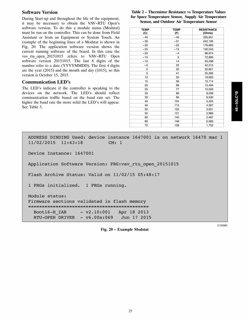
25
Software VersionDuring Start-up and throughout the life of the equipment,it may be necessary to obtain the VAV--RTU Open’ssoftware version. To do this a module status (Modstat)must be run on the controller. This can be done from FieldAssistant or from an Equipment or System Touch. Anexample of the beginning lines of a Modstat is shown inFig. 20. The application software version shows thecurrent running software of the board. In this case thevav_rtu_open_20151015 refers to VAV--RTU Opensoftware version 20151015. The last 8 digits of thenumber refer to a date (YYYYMMDD). The first 4 digitsare the year (2015) and the month and day (1015), so thisversion is October 15, 2015.
Communication LED’sThe LED’s indicate if the controller is speaking to thedevices on the network. The LED’s should reflectcommunication traffic based on the baud rate set. Thehigher the baud rate the more solid the LED’s will appear.See Table 3.
Table 2 – Thermistor Resistance vs Temperature Valuesfor Space Temperature Sensor, Supply Air Temperature
Sensor, and Outdoor Air Temperature Sensor
TEMP(C)
TEMP(F)
RESISTANCE(Ohms)
---40 ---40 335,651---35 ---31 242,195---30 ---22 176,683---25 ---13 130,243---20 ---4 96,974---15 5 72,895---10 14 55,298---5 23 42,3150 32 32,6515 41 25,39510 50 19,90315 59 15,71420 68 12,49425 77 10,00030 86 8,05635 95 6,53040 104 5,32545 113 4,36750 122 3,60155 131 2,98560 140 2,48765 149 2,08270 158 1,752
ADDRESS DINDING Used: device instance 1647001 is on network 16470 mac 111/02/2015 11:43:18 CM: 1
Device Instance: 1647001
Application Software Version: PRG:vav_rtu_open_20151015
Flash Archive Status: Valid on 11/02/15 05:48:17
1 PRGs initialized. 1 PRGs running.
Module status:Firmware sections validated in flash memory---------------------------------------------------------------------------------------- Boot16-H_IAR - v2.10:001 Apr 18 2013 RTU-OPEH DRIVER - v6.00a:069 Jun 17 2015
C150395
Fig. 20 -- Example Modstat
48---50LC*B

26
Table 3 – LED’sThe LED’s on the VAV--RTU Open show the status of certain functions
If this LED is on... Status is...
Power The VAV---RTU Open has power
Rx The VAV---RTU Open is receiving data from the network segment
Tx The VAV---RTU Open is transmitting data over the network segment
BO# The binary output is active
The Run and Error LED’s indicate control module and network status
If Run LED shows... And Error LED shows... Status is...
2 flashes per second Off Normal
2 flashes per second 2 flashes, alternating with Run LED Five minute auto--- restart delay after system error
2 flashes per second 3 flashes, then off Control module has just been formatted
2 flashes per second 4 flashes, then pause Two or more devices on this network have the sameMSTP network address
2 flashes per second On Exec halted after frequent system errors or control pro-grams halted
5 flashes per second On Exec start---up aborted, Boot is running
5 flashes per second Off Firmware transfer in progress, Boot is running
7 flashes per second 7 flashes per second, alternating withRun LED
Ten second recovery period after brownout
14 flashes per second 14 flashes per second, alternating withRun LED
Brownout
On On Failure. Try the following solutions:--- Turn the VAV---RTU Open off, then on.--- Format the VAV---RTU Open.--- Download memory to the VAV---RTU Open.--- Replace the VAV---RTU Open.
Table 4 – VAV--RTU Open Alarms
POINT NAME ACTION TAKEN BYCONTROL RESET METHOD PROBABLE CAUSE
Safety Chain Immediate Shutdown Automatic Over load Indoor Fan or Electric Heateroverheat
Fire Shutdown Immediate Shutdown Automatic Smoke detected by smoke detector orconfiguration incorrect
Gas Valve Immediately operate fan at highestspeed
Automatic Gas valve stuck open after heating cycle, causingheat to continue to operate.
Supply Fan Immediately disableOperation
Automatic Tripped Circuit Breaker, Broken belt, Bad indoorfan motor, Configuration incorrect, Bad fanstatus switch.
Supply Fan in Hand Ramp down Operations Automatic Bad Fan Status Switch, Configuration incorrect.
Compressor Status Alert Generated Automatic Compressor would not start
Space Temp Sensor Ramp down Operations Automatic Bad sensor, bad wiring, failure to receive Networkor Linkage Space Temp value, or sensorconfigured incorrectly.
ZS Sensor Alert Generated Automatic This alarm indicates a communication failure ofa connected ZS sensor that previously hadbeen actively communicating.
ZS Configuration Alert Generated Automatic This alarm indicates that at least one ZS sensoris configured in the Sensor Binder propertiesand is not actually communicating.
Supply Air Temp Sensor Ramp down Operations Automatic Faulty, shorted, or open thermistor caused bywiring error or loose connection.
Local OAT Sensor May cause Economizer and Low ambi-ent DX cooling lockout to be disabled
Automatic Faulty, shorted, or open thermistor caused bywiring error or loose connection.
Outdoor Air Temp Sensor Economizer and Low ambient DX cool-ing lockout disabled.
Automatic Failure to receive valid local or network valuefor Outdoor Air Temperature
Space RelativeHumidity Sensor
Dehumidification disabled Automatic Sensor reading is out of range. Bad sensor, badwiring, failure to receive Network or Linkage RHvalue, or sensor configured incorrectly.
Indoor Air Quality Sensor No IAQ Operation Automatic Sensor reading is out of range. Bad sensor, badwiring, failure to receive Network or Linkage RHvalue, or sensor configured incorrectly.
Outdoor Air Quality Sensor Control uses default OAQ value of 400ppm.
Automatic Sensor reading is out of range. Bad sensor, badwiring, failure to receive Network value, orsensor configured incorrectly.
48---50LC*B

27
Table 4 -- VAV--RTU Open Alarms (cont)
POINT NAME ACTION TAKEN BYCONTROL RESET METHOD PROBABLE CAUSE
Economizer Operation Alert Generated Automatic This alarm is active whenever an economizerfault is detected as required by the CaliforniaTitle 24 Economizer FDD logic.Economizer fault conditions include; Failed toFully Open, Failed to Open, Failed to Close,and Stuck Open.
Space Temperature Alert Generated Automatic Space Temperature value is less than the lowlimit value or greater than the high limit value
Supply Air Temperature Alert Generated Automatic SAT is greater than the high limit value or lessthan the low limit value for more than 5 minutes
Switch Configuration Disable only wrong switch functions Configure correctly More than one discrete input is configured toprovide the same function.
Analog InputConfiguration
Disable 4 selectable analog inputs Configure correctly More than one analog input is configured toprovide the same function.
Space Relative Humidity Alert Generated Automatic Indoor RH is greater than the high limit value orless than the low limit value for more then 15minutes
Indoor Air Quality Alert Generated Automatic CO2 ppm reading is above the configuration for1 minute
Supply Fan Runtime Alert Generated zero the timer Supply fan run time exceeded user defined limit
Compressor 1 Runtime Alert Generated zero the timer Compressor #1 run time limit is exceeded
Compressor 2 Runtime Alert Generated zero the timer Compressor #2 run time limit is exceeded
Heat 1 Runtime Alert Generated zero the timer Heat Stage 1 run time limit is exceeded
Heat 2 Runtime Alert Generated zero the timer Heat Stage 2 run time limit is exceeded
Filter Alert Generated Automatic / reset timer Dirty Filter, supply fan run time exceeded, filterswitch configuration wrong.
Airside Linkage Alarm Alert Generated Automatic Airside Linkage communication from VVTR or VAVmaster terminal has stopped or failed
48---50LC*B

28
AlarmsAlarms are provided to indicate a possible problem withthe controller or unit. Alarms can be checked through anetwork and/or the local access device. All alarms arelisted in Table 4 with name, object name, action taken bycontrol, reset method, and possible cause. Some alarmscan occur based on specific configurations.
Safety Chain AlarmThis alarm occurs immediately if a field installed, normallyclosed, safety contact opens and interrupts 24VAC signalinput #4 (J1--9). The Unit Status will be Shutdown and theSystem Mode will be Disable. All unit operations stopimmediately and will not restart until the alarmautomatically clears. There are no configurations for thisalarm; it is all based on field installed wiring. This alarmwill not occur if Fire Shutdown Alarm is active. Normaloperation resumes when the safety chain circuit is complete.
Fire/Smoke Shutdown AlarmThis alarm occurs immediately when the smoke detectorsenses smoke. The Unit Status will be Shutdown and theSystem Mode will be Disable. All unit operations stopimmediately and will not restart until the alarmautomatically clears. If there is not a smoke detectorinstalled or the smoke detector did not trip, check inputconfigurations.NOTE: The default function for input 5 is a normallyopen Fire Shutdown input.
Gas Valve AlarmThis alarm occurs 60 second after gas heat has beende--energized but the Integrated Gas Control (IGC) boardis still indicating a need for fan operation. Upon alarmdetection, the fan will start immediately and run at itshighest speed.NOTE: The default function for input 9 is a normallyopen IGC input for LC WeatherExpert units.
Supply Fan FailureThis alarm occurs when the indoor fan is being commandon and the fan status switch feedback is showing the fanoff. This will end current operating mode and disable unitoperation. This alarm requires a fan status switch to beconfigured on one of the inputs.
Supply Fan in HandThis alarm occurs when the indoor fan is beingcommanded off and the fan status switch feedback isshowing the fan is on. This will prevent any operatingmode and disable unit operation. This alarm requires a fanstatus switch to be configured on one of the inputs.
Compressor StatusThis alarm indicates the base unit’s compressor safetycircuit is energized. Cooling, heating, and supply fanoutputs are not interrupted. Normal operation resumeswhen the compressor safety circuit is de-energized. Thisalarm requires field use of this described compressorsafety circuit.
Space Temp SensorThe SPT value from the Network or Airside Linkage is nolonger being received. When this occurs the Unit Status willbe Shutdown and the System Mode will be Run. Sensor,
sensor connections, wiring, board connection, andconfigurations should be checked for faults or errors. Alarmwill reset automatically when cause is fixed.
ZS SensorThis alarm occurs if the ZS sensor wired to the VAV--RTUOpen stops communicating with the controller.ZS Sensor -- This alarm indicates a communicationfailure of a connected ZS sensor that previously had beenactively communicating. The alarm is reset when normalZS sensor communications resume, if power is cycled tothe controller, or if the Shutdown point is set to Active.ZS Configuration -- This alarm indicates that at least oneZS sensor is configured in the Sensor Binder propertiesand is not actually communicating. The alarm is resetwhen the configured ZS sensor is communicating or theconfiguration is changed to reflect the sensor is no longerconnected to the Rnet.
Supply Air Temp SensorThis alarm occurs immediately when the supply airtemperature sensor wired to the VAV--RTU Open isdisconnected or shorted. When this occurs the Unit Statuswill be Shutdown and the System Mode will be Run.Sensor, sensor connections, wiring, board connection, andconfigurations should be checked for faults or errors.Alarm will reset automatically when cause is fixed.
Local OAT SensorThis alarm occurs when the outdoor air sensor indicates ashort or open circuit or the Network OAT value is nolonger being received. Economizer cooling and optimalstart functions are disabled. Normal operation resumeswhen the controller detects a valid sensor.
Outdoor Air Temp SensorThis alarm indicates that a valid OAT sensor value is nolonger available to the controller after having beenavailable previously.Economizer Operation -- This alarm is active wheneveran economizer fault is detected as required by CaliforniaTitle 24 Economizer FDD logic. Once detected, this alarmwill stay active until the Shutdown input is set to Activeor the fan is stopped.Economizer -- This point indicates the specific faultdetected and annunciated by the Economizer Operationalarm above. Detected fault conditions include: Failed toFully Open, Failed to Open, Failed to Close, and StuckOpen.
Space Relative Humidity SensorThis alarm indicates the mA input at the associatedchannel falls below 3.5 mA or rises above 21 mA, or theNetwork value for space RH is no longer being received.Cooling, heating, and supply fan operation continues,however, the controller’s Humidi-MiZer binary output isdisabled until the fault condition is corrected.
IAQ SensorThis alarm indicates the mA input at the associatedchannel falls below 3.5 mA or rises above 21 mA, or theNetwork value for space RH is no longer being received.Cooling, heating, and supply fan operation continues.However, the controller’s IAQ control function is disableduntil the fault condition is corrected.
48---50LC*B
29
OAQ SensorThis alarm indicates the mA input at the associated channelfalls below 3.5 mA or rises above 21 mA, or the Networkvalue for space RH is no longer being received. Cooling,heating, and supply fan operation continues. However, thecontroller’s IAQ control function uses 400ppm as the fixedoutdoor air CO2 level until the fault condition is corrected.
Space TemperatureWhen Occupied, a Space Temperature alarm is generatedif the space temperature falls below the lower limit orrises above the upper limit.When Unoccupied, an unoccupied space temperaturealarm is generated when the space temperature falls belowthe alarm configuration Unoccupied Low SPT AlarmLimit or when the space temperature rises above the alarmconfiguration Unoccupied High SPT Alarm Limit.The following values are related to the Space Temperaturealarm:Alarming Temperature – This variable displays the valueof the space temperature that caused the alarm and is onlyvisible when the space temperature is in an alarm state.Alarm Limit Exceeded – This variable displays the valueof the alarm setpoint that was exceeded by the alarmingspace temperature and is only visible when the spacetemperature is in an alarm state.
Supply Air TemperatureThis alarm indicates the supply air temperature fell belowthe alarm configuration Low SAT Alarm Limit orexceeded the alarm configuration High SAT Alarm Limitfor 5 minutes. This alarm is inhibited until the RTU hasbeen running for 30 minutes to allow for systemstabilization after startup.
Switch ConfigurationThis occurs if more than one binary input (inputs 3, 5, and8) is configured for the same function. When this happensthe two inputs (or more) configured wrong will bedisabled as an inputs. This alarm will automatically becleared when configuration is corrected.An example of this would be: Input 3 = CompressorSafety, input 5 = Fan Status, and input 8 = Fan Status; thealarm would be active, unit would run, compressor safety,and Fan Status (inputs 5 & 8) will be interpreted as “NoFunction.”
Analog Input ConfigurationThis occurs if more than one analog input (inputs 1 & 2)is configured for the same sensor. When this happens thetwo inputs will be disabled as inputs. This alarm willautomatically be cleared when configuration is corrected.An example of this would be: Input 1 = IAQ Sensor, input2 = IAQ Sensor; the alarm would be active, unit wouldrun, but the IAQ Sensor (inputs 1 & 2) will be interpretedas “No Function.”
Space Relative HumidityThis alarm indicates the space humidity fell below thealarm configuration Low Space Humidity Alarm Limit orexceeded the alarm configuration High Space HumidityAlarm Limit for 10 minutes. This alarm is inhibited untilthe RTU runs for 15 minutes to allow for systemstabilization after startup.
Indoor Air QualityThis alarm indicates the space CO2 level exceeds thealarm configuration Occupied High CO2 Alarm Limit for1-minute. This alarm will be inhibited until the RTU hasbeen running for 2-minutes to allow for systemstabilization after startup.
Supply Fan RuntimeThis alarm indicates the accumulated runtime exceeds theunit configuration Supply Fan Service Alarm Timer value(when not set to 0). This alarm is most commonly used toindicate an equipment maintenance interval is due. Thesupply fan runtime accumulator may be reset by settingthe maintenance point Reset Supply Fan Runtime Alarmto Clear, and then back to Run – acknowledging eachselection by clicking the OK button when it appears.Setting unit configuration Supply Fan Service Timer valueto 0 disables the supply fan runtime alarm function.
Compressor 1 RuntimeThis alarm indicates the accumulated runtime exceeds theunit configuration Compressor 1 Service Alarm Timer value(when not set to 0). This alarm is most commonly used toindicate an equipment maintenance interval is due. TheCompressor 1 Runtime accumulator may be reset by settingthe maintenance point Reset Comp 1 Runtime Alarm toClear, and then back to Run – acknowledging each selectionby clicking the OK button when it appears. Setting unitconfiguration Compressor 1 Service Timer value to 0disables the Compressor 1 Runtime alarm function.
Compressor 2 RuntimeThis alarm indicates the accumulated runtime exceeds theunit configuration Compressor 2 Service Alarm Timervalue (when not set to 0). This alarm is most commonlyused to indicate an equipment maintenance interval is due.The Compressor 2 runtime accumulator may be reset bysetting the maintenance point Reset Comp 2 RuntimeAlarm to Clear, and then back to Run – acknowledgingeach selection by clicking the OK button when it appears.Setting unit configuration Compressor 2 Service Timervalue to 0 disables the Compressor 2 runtime alarmfunction. Note that this function is unavailable if theservice configuration Compressor Stages value is not setto Two Stages.
Heat 1 RuntimeThe VAV--RTU Open generates this alarm when theaccumulated runtime exceeds the Unit Configuration >Heat 1 Service Alarm Timer value (when not set to 0).This alarm is most commonly used to indicate anequipment maintenance interval is due. The Heat 1Runtime accumulator may be reset by setting theMaintenance > Reset Heat 1 Runtime Alarm to Clear, andthen back to Run – acknowledging each selection byclicking the OK button when it appears. Setting UnitConfiguration > Heat 1 Service Timer value to 0 disablesthe Heat 1 Runtime alarm function.
Heat 2 RuntimeThe VAV--RTU Open generates this alarm when theaccumulated runtime exceeds the Unit Configuration >Heat 2 Service Alarm Timer value (when not set to 0).This alarm is most commonly used to indicate anequipment maintenance interval is due. The Heat 2
48---50LC*B
30
Runtime accumulator may be reset by setting theMaintenance > Reset Heat 2 Runtime Alarm to Clear, andthen back to Run – acknowledging each selection byclicking the OK button when it appears. Setting UnitConfiguration > Heat 2 Service Timer value to 0 disablesthe Heat 2 Runtime alarm function. Note that thisfunction is unavailable if the Service Configuration >Heat Stages value is not set to Two Stages.
FilterThis alarm indicates the accumulated runtime exceeds theunit configuration Filter Service Alarm Timer value(when not set to 0). This alarm is most commonly used toindicate a filter replacement is due. Reset the filter serviceruntime accumulator by setting the maintenance pointReset Filter Runtime Alarm to On, back to Off, andclicking the OK button after each setting. Setting unitconfiguration Filter Service Alarm Timer value to 0disables the filter service alarm function.
Airside Linkage AlarmThis alarm indicates that VAV--RTU Open was connectedto a zoned system using Airside Linkage and it lostcommunications with its linkage master or it is receivingdata from multiple masters.
PerformanceCurrent Performance DataThe VAV--RTU Open collects performance data duringoperation. The data can be used to monitor the operationof the unit over time.
Equipment RuntimeThe RTU monitors the supply fan and records the amountof time the unit has been operating. This value willcontinue to accumulate runtime until Performance Datahas been changed to Reset or will also automatically resetevery 24 hours at midnight if Save Performance DataDaily is set to Enable.
Economizer UtilizationThe amount of time the equipment has operated in theeconomizer mode as a percentage of the equipmentruntime above. This value will continue to accumulateruntime until Performance Data has been changed toReset or will automatically reset every 24 hours atmidnight if Save Performance Data Daily is set to Enable.
DCV UtilizationThe amount of time the equipment has provided DemandControlled Ventilation as a percentage of the equipmentruntime above. This value will continue to accumulateruntime until Performance Data has been changed toReset or will automatically reset every 24 hours atmidnight if Save Performance Data Daily is set to Enable.
Unocc Free Cool UtilizationThe amount of time the equipment has provided FreeCooling while unoccupied as a percentage of theequipment runtime above. This value will continue toaccumulate runtime until Performance Data has beenchanged to Reset or will automatically reset every 24hours at midnight if Save Performance Data Daily is set toEnable.
Part Load Cooling UtilizationThe amount of time the equipment has operated in thecooling mode but at less than 100% full cooling capacityas a percentage of the equipment runtime above. Thisvalue will continue to accumulate runtime untilPerformance Data has been changed to Reset or willautomatically reset every 24 hours at midnight if SavePerformance Data Daily is set to Enable.
Full Load Cooling UtilizationThe amount of time the equipment has operated in thecooling mode at 100% full cooling capacity as apercentage of the equipment runtime above. This valuewill continue to accumulate runtime until PerformanceData has been changed to Reset or will automatically resetevery 24 hours at midnight if Save Performance DataDaily is set to Enable.
Heating UtilizationThe amount of time the equipment has operated in theheating mode as a percentage of the equipment runtimeabove. This value will continue to accumulate runtimeuntil Performance Data has been changed to Reset or willautomatically reset every 24 hours at midnight if SavePerformance Data Daily is set to Enable.
Recorded High OATThe highest value of OAT noted since the last resetoccurred. This value will continue to update untilPerformance Data has been changed to Reset or willautomatically reset every 24 hours at midnight if SavePerformance Data Daily is set to Enable.
Recorded Low OATThe lowest value of OAT noted since the last resetoccurred. This value will continue to update untilPerformance Data has been changed to Reset or willautomatically reset every 24 hours at midnight if SavePerformance Data Daily is set to Enable
Performance DataIndicates the mode that is currently in effect. This point isused to reset all of the above performance data manuallyat any time.
Range = Collect/Reset Default = Collect
Historical Performance DataThe VAV--RTU Open collects historical performanceevery time the performance data above has been reset.
Save Performance Data DailyIf set to Enable, the control will automatically transfer theCurrent Performance Data directly to the HistoricalPerformance Data values for each entry once every 24 hoursat midnight. All Historical data will only be available forviewing for the next 24 hours. Also, all current performancedata will be reset after the data has been transferred.
Range = Disable/Enable Default = Enable
Equipment RuntimeThe value of the equipment runtime when the currentperformance data was last reset.
Economizer UtilizationThe value of the Economizer Utilization when the currentperformance data was last reset.
48---50LC*B

31
DCV UtilizationThe value of the DCV Utilization when the currentperformance data was last reset.
Unocc Free Cool UtilizationThe value of the Unocc Free Cool Utilization when thecurrent performance data was last reset.
Part Load Cooling UtilizationThe value of the Part Load Cooling Utilization when thecurrent performance data was last reset.
Full Load Cooling UtilizationThe value of the Full Load Cooling Utilization when thecurrent performance data was last reset.
Heating UtilizationThe value of the Heating Utilization when the currentperformance data was last reset.
Previous High OATThe value of the Recorded High OAT when the currentperformance data was last reset.
Previous Low OATThe value of the Recorded Low OAT when the currentperformance data was last reset.
Table 5 – Manufacture DateWhen troubleshooting, you may need to know a control module’s manufacture date.
Obtain the manufacture date from a... Notes
Module status report (modstat) To obtain a modstat with Field Assistant:1. Press Function (FN) key and hold.2. Then press period (.)3. Release both buttons.The report shows the date under Main board hardware.
Sticker on the control board“Serial No: OR2YMCxxxP”(Bar Coded & Typed Number)
The serial numbers are unique and contain embedded information, for example OR2420042P:“VRT” --- These first three digits are unique to VAV---RTU Open and are used as an identifier.“YM” --- These two digits identify the last digit of the year and month (in hex, A=10/Oct)
of manufacture. “42” would represent a date of manufacture of “Feb 2014”.“C” --- Thousands counter 0---9 and A---Z; A = 10; Z = 35“xxx” --- These three digits represent the sequential number of units produced for a given
product for the mentioned manufacturing time period.“P” --- This final digit represents the decade and toggles between “N” and “M” every
ten years.
Table 6 – Basic Protocol Troubleshooting
Problem Possible cause Corrective action
No communication with 3rdparty vendor
Incorrect settings on SW1, SW2 and SW3 Verify and correct switch settings. Cyclepower to VAV---RTU Open after changingswitch settings.
RS485 Port has no voltage output(check with VAV---RTU Open disconnected from RS485communication bus):
• BacnetR@ 9600/19.2K --- .01 to .045vdc• Bacnet @ 38.4K --- .06 to .09vdc• Bacnet @ 76.8K --- .1vdc
Verify VAV---RTU Open has correct powersupply.
Possible bad driver on board.
Check RS485 bus for external voltagebefore reconnecting to the bus.
Verify devices are daisy chained and repeaters and biasterminators are correctly installed.
Check 3rd party vendor RS485communication wiring guidelines andtroubleshooting procedures.
48---50LC*B
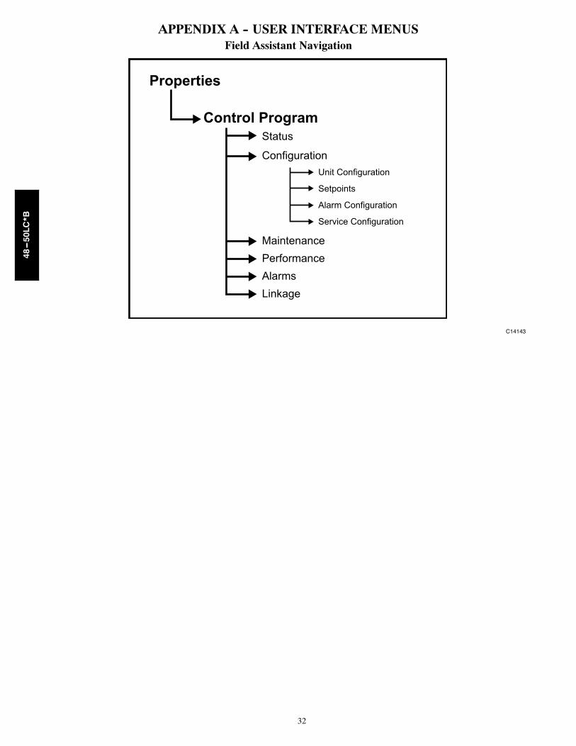
32
APPENDIX A -- USER INTERFACE MENUSField Assistant Navigation
Properties
Control ProgramStatus
ConfigurationUnit Configuration
Setpoints
Alarm Configuration
Service Configuration
MaintenancePerformanceAlarmsLinkage
C14143
48---50LC*B

33
APPENDIX A -- USER INTERFACE MENUS (CON’T)
Equipment Touch orSystem Touch Menu
Access Level3 = ADMIN2 = USER1 = None
POINT NAME RANGE DEFAULT Field Assistant Menu
STATUSProperties Pages>Status 3, 2, 1 Equipment Status 1 = Disabled
2 = Test3=RunProperties>Control Program>Status
3, 2, 1 System Mode 1 = Off2 = Fan Only3 = Economizer Cooling4 = Cooling5 = Heating6 = Dehumidification7 = Test8 = Shutdown9 = Unocc Free Cooling10 = Fire Shutdown11 =I AQ Override12 = Pre-occ Purge13 = IGC Override
3, 2, 1 Supply Fan Status1 Off / Running3, 2, 1 Static Pressure -xxx.x - xxx.x "wc3, 2, 1 Supply Fan VFD 0-100 %3, 2, 1 Supply Air Temperature - Prime Variable -xxx.x - xxx.x °F3, 2, 1 Return Air Temperature -xxx.x - xxx.x °F3, 2, 1 Space Temperature2 -xxx.x - xxx.x °F3, 2, 1 Outdoor Air Temperature -xxx.x - xxx.x °F3, 2, 1 Enthalpy Status -xxx.x - xxx.x °F3, 2, 1 Space Relative Humidity3 0-100 %3, 2, 1 Indoor Air Quality CO2
4 0-5000 ppm3, 2, 1 Outdoor Air Quality CO2
5 0-5000 ppm3, 2, 1 Economizer Output 0-100 % Open3, 2, 1 Shutdown Inactive/Active Inactive
UNIT CONFIGURATIONProperty Pages>Configuration>Unit Configuration
3 Fan Mode 1 = Auto2 = Continuous3 = Always On
Continuous Properties>Control Program>Configuration>Unit Configuration
3 Power Fail Restart Delay 0-30 sec 53 Fan Off Delay 5-120 sec 903 Occupied Heating Disable/Enable Disable3 Supply Air Temp Reset Disable/Enable Disable3 Reset Ratio 0-10 33 Reset Maximum Limit 0 - 25°F 103 Humidity Override Disable/Enable Disable3 Minimum Cooling SAT6 45 - 75°F 453 Maximum Heating SAT 90 - 150°F 1203 Vent Dmpr Pos / DCV Min Pos 0-100 % Open 203 Low Fan Econ Min Pos 0-100 % Open 333 DCV Max Vent Damper Pos 0-75 % Open 503 Static Pressure Reset Enable Disabled/Enabled Enabled3 Maximum Damper Position 0-100 % Open 803 Minimum Damper Position 0-100 % Open 503 Maximum Reset 0.00 to 2.00 "wc 0.253 SP Reset Demand Level 1 = Not Active
2 = Cool Dmd Lvl 13 = Cool Dmd Lvl 24 = Cool Dmd Lvl 3
Not Active
3 Supply Fan Service Alarm Timer 0-9999 hr 6003 Comp 1 Service Alarm Timer 0-9999 hr 03 Comp 2 Service Alarm Timer 0-9999 hr 03 Filter Service Alarm Timer 0-9999 hr 6003 Heat 1 Service Alarm Timer 0-9999 hr 03 Heat 2 Service Alarm Timer 0-9999 hr 03 Cooling Lockout Temperature -65 - 80°F 453 Economizer High OAT Lockout Temp 55 - 80°F 753 Heating Lockout Temperature 35 - 150°F 653 Unocc Free Cool Disable/Enable Disable3 Min Setpoint Separation 2-10∆ °F 5∆
1 This input will only be shown if Input Configuration>Input 5, 8 or 9 Function is set to 3 = Fan Status2 Displayed value that the VAV-RTU Open controller is controlling to3 This input will only be shown if Input Configuration>Input 2 Function is set to 3 = Space RH Sensor and there is a valid Space Relative Humidity value on J4 -2&34 This input will only be shown if Input Configuration>Input 2 Function is set to 2 = IAQ Sensor and there is a valid Indoor Air Quality CO2 Sensor value on J4 -2&35 This input will only be shown if Input Configuration>Input 2 Function is set to 2 = OAQ Sensor, there is a valid Indoor Air Quality CO2 Sensor value on J4 -2&3, and Service
Configuration>DCV Control is set to Enable at one of the VAV Zone controllers which has Service Configuration>Hardwired Sensor set to CO2 Sensor with a valid value on J4 - RH&Gnd6 Default to meet California Title 24 requirements is 45°F
48---50LC*B

34
APPENDIX A -- USER INTERFACE MENUS (CON’T)
Equipment Touch orSystem Touch Menu
Access Level3 = ADMIN2 = USER1 = None
POINT NAME RANGE DEFAULT Field Assistant Menu
INPUT CONFIGURATIONProperty Pages>Configuration>Unit Configuration>Input Configuration
3 Input 2 Function 1 = No Sensor2 = IAQ Sensor3 = Space RH Sensor4 = OAQ Sensor
No Sensor Properties>Control Program>Configuration>Unit Configuration>Input Configuration
3 Input 3 Function 1 = No Function2 = Compressor Safety3 = Fan Status4 = Filter Status5 = Remote Occupancy7
6 = Door Contact7
No Function
3 Input 3 Switch Configuration8 1 = NO (Normally Open)2 = NC (Normally Closed)
NO
3 Input 5 Function 1 = No Function2 = Fire Shutdown3 = Fan Status4 = Filter Status5 = Remote Occupancy7
6 = Door Contact7
Fire Shutdown
3 Input 5 Switch Configuration 1 = NO (Normally Open)2 = NC (Normally Closed)
NO
3 Input 8 Function8 1 = No Function2 = Enthalpy Switch3 = Fan Status4 = Filter Status5 = Remote Occupancy7
6 = Door Contact7
No Function
3 Input 8 Switch Configuration8 1 = NO (Normally Open)2 = NC (Normally Closed)
NO
3 Input 9 Function9 1 = No Function2 = Humidistat7
3 = Fan Status4 = Filter Status5 = Remote Occupancy7
6 = Door Contact7
7 = IGC Override
No Function
3 Input 9 Switch Configuration8 9 NO (Normally Open)NC (Normally Closed)
NO
N/A ZS sensor type10 1 = ZS Base2 = ZS Plus3 = ZS Pro
None
SENSOR CALIBRATIONProperty Pages>Configuration>Unit Configuration>Sensor Calibration
3 Space RH3 %rh Properties>Control Program>Configuration>Unit Configuration>Sensor Calibration
3 Space AQ4 ppm3 Outdoor AQ5 ppm3 Static Pressure 0.00 - 2.50 "wc3 Static Pressure Calibration -0.2 - 0.20 "wc 03 Supply Air Temperature -56 - 245°F3 Supply Air Temp Calibration -9.9 - 10∆°F 0∆3 Return Air Temperature -56 - 245°F3 Return Air Temp Calibration -9.9 - 10∆°F 0∆3 Outdoor Air Temperature -56 - 245°F3 Outdoor Air Temp Calibration -9.9 - 10∆°F 0∆
SETPOINTSProperty Pages>Configuration>Setpoints
3 Supply Air Setpoint 45 - 75°F 53 Properties>Control Program>Configuration>Setpoints
3 Static Pressure Setpoint 0.25 - 2.25 "wc 0.53 SA Tempering Setpoint11 40 - 75°F 48
Occ Relative Humidity Setpoint 0%RH to Unoccupied RH ControlSetpoint
60
DCV Max Ctrl Setpoint 0 to 9999 ppm 11003 Power Exhaust Setpoint 20 to 90% Open 50
3 This input will only be shown if Input Configuration>Input 2 Function is set to 3 = Space RH Sensor and there is a valid Space Relative Humidity value on J4 -2&34 This input will only be shown if Input Configuration>Input 2 Function is set to 2 = IAQ Sensor and there is a valid Indoor Air Quality CO2 Sensor value on J4 -2&35 This input will only be shown if Input Configuration>Input 2 Function is set to 2 = OAQ Sensor, there is a valid Indoor Air Quality CO2 Sensor value on J4 -2&3, and Service
Configuration>DCV Control is set to Enable at one of the VAV Zone controllers which has Service Configuration>Hardwired Sensor set to CO2 Sensor with a valid value on J4 - RH&Gnd7 Do Not Use8 Input Switch Configuration must be set for each Input Function9 This input will only be shown if Service Configuration>Heat Type is set to Electric. For gas units (Service Configuration> Heat Type set to 1 = Gas (48 series units) this input is
automatically set to 7 = IGC Override10 This input will only be shown when a ZS sensor is connected to J1311 This setpoint will only be shown if Service Configuration>SA Tempering is set to Enable
48---50LC*B

35
APPENDIX A -- USER INTERFACE MENUS (CON’T)
Equipment Touch orSystem Touch Menu
Access Level3 = ADMIN2 = USER1 = None
POINT NAME RANGE DEFAULT Field Assistant Menu
HIGH STATIC PRESSURE ALARM
Property Pages>Configuration>Alarm Configuration
3 SP High Limit Trip Setpoint 0 to 2.50 "wc 1.50 Properties>Control Program>Configuration>Alarm Configuration>
SUPPLY AIR TEMPERATURE ALARM
Property Pages>Configuration>Alarm Configuration
3 Low SAT Alarm Limit 15-90°F 38 Properties>Control Program>Configuration>Alarm Configuration>
3 High SAT Alarm Limit 90-175°F 160
RETURN AIR TEPERATURE ALARM
Property Pages>Configuration>Alarm Configuration
3 Low RAT Alarm Limit 15-90°F 38 Properties>Control Program>Configuration>Alarm Configuration>
3 High RAT Alarm Limit 90-175°F 120
SPACE HUMIDITY ALARM
Property Pages>Configuration>Alarm Configuration
3 Occupied High RH Alarm Limit 0-100%RH 70 Properties>Control Program>Configuration>Alarm Configuration>
3 Alarm Delay (min/%RH) 0-30 min 5
3 Unoccupied High RH Alarm Limit 0-100%rh 100
3 Low RH Alarm Limit 0-100%rh 30
IAQ / VENTILATION ALARM
Property Pages>Configuration>Alarm Configuration
3 Occ High CO2 Alarm Limit 0-9999 ppm 1200 Properties>Control Program>Configuration>Alarm Configuration>
SERVICE CONFIGURATION
Property Pages>Configuration>Service Configuration
3 Compressor Stages12 N/A Three Stages Properties>Control Program>Configuration>Service Configuration
3 Economizer Exists13 N/A Yes (FIOP)
3 VFD Input 0-10Vdc/2-10Vdc 2-10Vdc
3 Max VFD Output 15-100% 100
3 Min VFD Output 15-100% 25
3 Heat Type 0 = Electric (50 series units)1 = Gas (48 series units)
Gas
3 Number of Heat Stages 1 = 1 stage (All 50LC*B07-09units, 50LC*B12-14 lo heat)
2 = 2 stages (All 48LC*B07-26units, 50LC*B12 hi heat,50LC*B14 med/hi heat, All50LC*B17-26 units)
2
3 SA Tempering Disabled/Enabled Disable
3 Continuous Occupied Exhaust No/Yes No
3 DCV Control Disable/Enable Disable
3 Indoor CO2 Sensor Value @ Min mA14 0-9999ppm 0
3 Indoor CO2 Sensor Value @ Max mA14 0-9999ppm 2000
3 Outdoor CO2 Sensor Value @ Min mA15 0-9999ppm 0
3 Outdoor CO2 Sensor Value @ Max mA15 0-9999ppm 2000
3 Static Pressure Sensor Value @ Min mA 0
3 Static Pressure Sensor Value @ Max mA 2.5
3 System Space RH N/A -999.0
3 System Space AQ N/A -999.0
3 System Cool Demand Level 0-3 0
3 System Heat Demand Level 0-3 0
3 System Outdoor Air Temperature N/A -999.0
3 System Outdoor AQ N/A -999.0
3 System Fire / Smoke Off/On Off
3 Network Heat Interlock Not Used
12 Compressor Stages default is Three Stages and cannot be changed13 Economizer Exist default is Yes and cannot be changed14 This configuration will only be shown if Input Configuration>Input 2 Function is set to 2 = IAQ Sensor15 This configuration will only be shown if Input Configuration>Input 2 Function is set to 4 = OAQ Sensor
48---50LC*B

36
APPENDIX A -- USER INTERFACE MENUS (CON’T)
Equipment Touch orSystem Touch Menu
Access Level3 = ADMIN2 = USER1 = None
POINT NAME RANGE DEFAULT Field Assistant Menu
SERVICE TEST
Property Pages>Configuration>Service Configuration
3 Service Test Mode Disable/Enable Properties>Control Program>Configuration>Service Configuration>Service Test
3 Service Test Disable/Enable Disable
3 Fan Test Disable/Enable Disable
3 Compressor 1 Test Disable/Enable Disable
3 Compressor 2 Test Disable/Enable Disable
3 Heat 1 Test Disable/Enable Disable
3 Heat 2 Test Disable/Enable Disable
3 Heat Interlock Relay Test Disable/Enable Disable
3 Power Exhaust Test Disable/Enable Disable
3 Economizer Test 0-100 %Open 0
3 VFD Speed Test 0-100% 0
MAINTENANCE (UNIT)
Property Pages>Maintenance>Unit
3 Occupancy Status Occupied/Unoccupied Properties>Control Program>Maintenance>Unit
3 Current Static Pressure Setpoint "wc
3 Calculated Static Pressure Reset "wc
3 HPCO Status Normal/Shutdown
3 Reset Tripped HPCO16 Run / Reset
3 Static Pressure Proof Not ActiveValid SP ProofWait SP ProofSP Proof Timeout
3 Supply Air Setpoint °F
3 Supply Air Temp Clg. Setpoint °F
3 SAT Reset Source No ResetSAT Rst by SPTSAT Rst ovr RH
3 SAT Reset Value °F
3 RH Reset Override °F
3 Heating Control Setpoint °F
3 Calculated Max Heat SAT Limit °F
3 Space Temp Source Sensor FailureAirside LinkageLocked Value
3 Effective Heat Setpoint °F
3 Effective Cool Setpoint °F
3 Relative Humidity Source 1 = N/A2 = Local3 = Network4 = Linkage5 = Locked Value6 = Linkage & Local7 = ZS Sensor8 = Linkage & ZS Sensor
3 IAQ Source 1 = N/A2 = Local3 = Network4 = Linkage5 = Locked Value6 = Linkage & Local7 = ZS Sensor8 = Linkage & ZS Sensor
3 Outdoor Air Temperature Source 1 = N/A2 = Local3 = Network4 = Linkage5 = Locked Value6 = Linkage & Local7 = ZS Sensor8 = Linkage & ZS Sensor
16 This input will only be shown if HPCO Shutdown is in alarm. This is the reset point for the alarm.
48---50LC*B
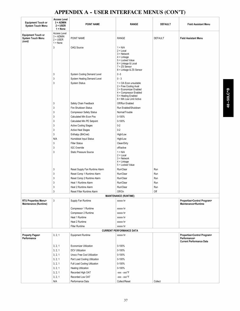
37
APPENDIX A -- USER INTERFACE MENUS (CON’T)
Equipment Touch orSystem Touch Menu
Access Level3 = ADMIN2 = USER1 = None
POINT NAME RANGE DEFAULT Field Assistant Menu
Equipment Touch orSystem Touch Menu(cont)
Access Level3 = ADMIN2 = USER1 = None
POINT NAME RANGE DEFAULT Field Assistant Menu
3 OAQ Source 1 = N/A2 = Local3 = Network4 = Linkage5 = Locked Value6 = Linkage & Local7 = ZS Sensor8 = Linkage & ZS Sensor
3 System Cooling Demand Level 0 -3
3 System Heating Demand Level 0 - 3
3 System Status 1 = OA Econ unsuitable2 = Free Cooling Avail3 = Economizer Enabled4 = Compressor Enabled5 = Heating Enabled6 = MA Low Limit Active
3 Safety Chain Feedback Off/Run Enabled
3 Fire Shutdown Status Run Enabled/Shutdown
3 Compressor Safety Status Normal/Trouble
3 Calculated Min Econ Pos 0-100%
3 Calculated Min PE Setpoint 0-100%
3 Active Cooling Stages 0-2
3 Active Heat Stages 0-2
3 Enthalpy (BACnet) High/Low
N/A Humidistat Input Status High/Low
3 Filter Status Clean/Dirty
3 IGC Override off/active
3 Static Pressure Source 1 = N/A2 = Local3 = Network4 = Linkage5 = Locked Value
3 Reset Supply Fan Runtime Alarm Run/Clear Run
3 Reset Comp 1 Runtime Alarm Run/Clear Run
3 Reset Comp 2 Runtime Alarm Run/Clear Run
3 Heat 1 Runtime Alarm Run/Clear Run
3 Heat 2 Runtime Alarm Run/Clear Run
3 Reset Filter Runtime Alarm Off/On Off
MAINTENANCE (RUNTIME)
RTU Properties Menu>Maintenance (Runtime)
3 Supply Fan Runtime xxxxx hr Properties>Control Program>Maintenance>Runtime
Compressor 1 Runtime xxxxx hr
Compressor 2 Runtime xxxxx hr
Heat 1 Runtime xxxxx hr
Heat 2 Runtime xxxxx hr
Filter Runtime xxxxx hr
CURRENT PERFORMANCE DATA
Property Pages>Performance
3, 2, 1 Equipment Runtime xxxxx hr Properties>Control Program>Performance>Current Performance Data
3, 2, 1 Economizer Utilization 0-100%
3, 2, 1 DCV Utilization 0-100%
3, 2, 1 Unocc Free Cool Utilization 0-100%
3, 2, 1 Part Load Cooling Utilization 0-100%
3, 2, 1 Full Load Cooling Utilization 0-100%
3, 2, 1 Heating Utilization 0-100%
3, 2, 1 Recorded High OAT -xxx - xxx°F
3, 2, 1 Recorded Low OAT -xxx - xxx°F
N/A Performance Data Collect/Reset Collect
48---50LC*B

38
APPENDIX A -- USER INTERFACE MENUS (CON’T)
Equipment Touch orSystem Touch Menu
Access Level3 = ADMIN2 = USER1 = None
POINT NAME RANGE DEFAULT Field Assistant Menu
HISTORICAL PERFORMANCE DATA
Save Performance Data Daily Disable/Enable Enable Properties>Control Program>Performance>Historical Performance Data
Equipment Runtime xxxxx.x hr
Economizer Utilization 0-100%
Field Assistant Only DCV Utilization 0-100%
Unocc Free Cool Utilization 0-100%
Part Load Cooling Utilization 0-100%
Full Load Cooling Utilization 0-100%
Heating Utilization 0-100%
Previous High OAT -xxx - xxx°F
Previous Low OAT -xxx - xxx°F
ALARMS
Property Pages>Alarms 3, 2, 1 Safety Chain Normal/Alarm Properties>Control Pro-gram>Alarms
3, 2, 1 Fire / Smoke Shutdown Normal/Alarm
3, 2, 1 Gas Valve Normal/Alarm
3, 2, 1 HPCO Shutdown Normal/Alarm
3, 2, 1 SP Proof (status) Not ActiveValid SP ProofWait SP ProofSP Proof Timeout
3, 2, 1 Compressor Status Normal/Alarm
3, 2, 1 ZS Sensor Configuration Normal/Alarm
3, 2, 1 Space Temp Sensor Normal/Alarm
3, 2, 1 Supply Air Temperature Normal/Alarm
3, 2, 1 Supply Air Temp Sensor Normal/Alarm
3, 2, 1 Return Air Temperature Normal/Alarm
3, 2, 1 Return Air Temp Sensor Normal/Alarm
3, 2, 1 Supply Fan Failure Normal/Alarm
3, 2, 1 Supply Fan in Hand Normal/Alarm
3, 2, 1 Indoor Air Quality Normal/Alarm
3, 2, 1 Indoor Air Quality Sensor Normal/Alarm
3, 2, 1 Space Relative Humidity Normal/Alarm
3, 2, 1 Space Relative Humidity Sensor Normal/Alarm
3, 2, 1 Filter Clean/Dirty
3, 2, 1 Local OAT Sensor Normal/Alarm
3, 2, 1 Outdoor Air Temp Sensor Normal/Alarm
3, 2, 1 Economizer Operation Normal/Alarm
3, 2, 1 Economizer 1 = Normal2 = Failed to Fully Open3 = Failed to Open4 = Failed to Close5 = Stuck Open
3, 2, 1 Switch Configuration Normal/Alarm
3, 2, 1 Analog Input Configuration Normal/Alarm
3, 2, 1 Supply Fan Runtime Normal/Alarm
3, 2, 1 Compressor 1 Runtime Normal/Alarm
3, 2, 1 Compressor 2 Runtime Normal/Alarm
3, 2, 1 Heat 1 Runtime Normal/Alarm
3, 2, 1 Heat 2 Runtime Normal/Alarm
3, 2, 1 Airside Linkage Normal/Alarm
3, 2, 1 Static Pressure Sensor Normal/Alarm
3, 2, 1 Outdoor Air Quality Sensor Normal/Alarm
48---50LC*B
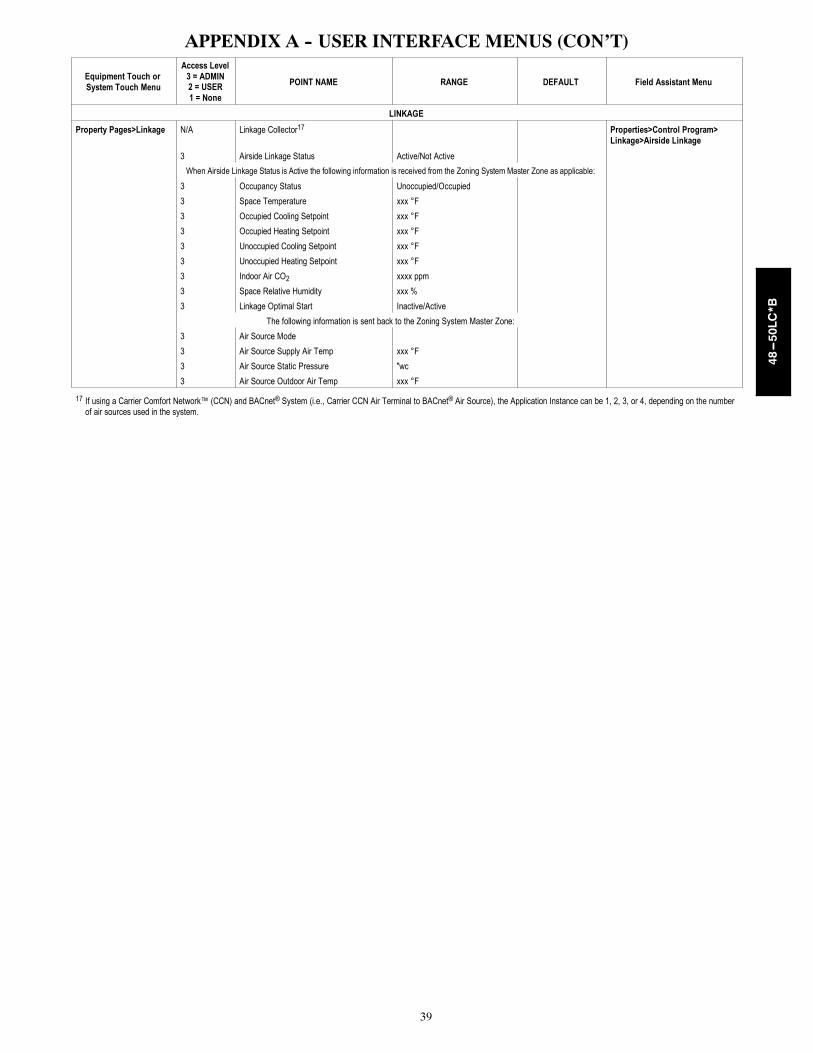
39
APPENDIX A -- USER INTERFACE MENUS (CON’T)
Equipment Touch orSystem Touch Menu
Access Level3 = ADMIN2 = USER1 = None
POINT NAME RANGE DEFAULT Field Assistant Menu
LINKAGE
Property Pages>Linkage N/A Linkage Collector17 Properties>Control Program>Linkage>Airside Linkage
3 Airside Linkage Status Active/Not Active
When Airside Linkage Status is Active the following information is received from the Zoning System Master Zone as applicable:
3 Occupancy Status Unoccupied/Occupied
3 Space Temperature xxx °F
3 Occupied Cooling Setpoint xxx °F
3 Occupied Heating Setpoint xxx °F
3 Unoccupied Cooling Setpoint xxx °F
3 Unoccupied Heating Setpoint xxx °F
3 Indoor Air CO2 xxxx ppm
3 Space Relative Humidity xxx %
3 Linkage Optimal Start Inactive/Active
The following information is sent back to the Zoning System Master Zone:
3 Air Source Mode
3 Air Source Supply Air Temp xxx °F
3 Air Source Static Pressure "wc
3 Air Source Outdoor Air Temp xxx °F
17 If using a Carrier Comfort Network™ (CCN) and BACnet® System (i.e., Carrier CCN Air Terminal to BACnet® Air Source), the Application Instance can be 1, 2, 3, or 4, depending on the numberof air sources used in the system.
48---50LC*B

40
APPENDIX B -- VAV ZONE AIRSIDE LINKAGE CONFIGURATION
Equipment Touch orSystem Touch Menu
Access Level3 = ADMIN2 = USER1 = None
POINT NAME RANGE DEFAULT Field Assistant Menu
AIRSIDE LINKAGE
Air TerminalProperties>Startup Wizard>Airside Linkage Configuration
N/A Linkage CollectorIf Master zone, set Number of Providersto the total # of controllers that will reportto the Master, including the masterFor a slave zone the # of providers is 1
1 to 64 1 Properties>Control Program>Linkage>Airside Linkage
N/A Linkage ProviderIf Master zone, set MS/TP networknumber and MAC address of the RTU(air source) with the VAV-RTU OpencontrollerFor a slave zone leave at zero
Network Number: 0 to 65,535MAC Address: 0 to 127
00
N/A Airside Linkage Status Active/Not Active
3 Linkage Zone Type SlaveVVT MasterVAV Master
Slave
3 Inhibit Heating Call from this zone? No/Yes No
N/A Active Heating Caller? No/Yes
3 Inhibit Cooling Call from this zone? No/Yes No
N/A Active Cooling Caller? No/Yes
3 Linkage RH Type Avg/Max Avg
3 Linkage IAQ Type Avg/Max Avg
N/A Air Source Mode OffWarmupHeatCoolFreecoolPressureEvacVent
N/A Air Source Supply Air Temp °F
N/A Air Source Static Pressure in wc
3 Air Source Outdoor Air Temp °F
3 Number of ProvidersIf Master zone, set Number of Providersto the total # of controllers that will reportto the Master, including the masterFor a slave zone the # of providers is 1
1 to 64 1
Air Terminal Properties>Startup Wizard>Airside Linkage Configuration>Air Source Configuration
3 Air Source (RTU)(Collector) Network # 0 to 65,535 0 Properties>Control Program>Linkage>Airside Linkage3 Air Source Address Type MSTP or IP MSTP
3 MS/TP Address 0 to 137 0
48---50LC*B

41
APPENDIX C -- VAV ZONE CONTROLLER -- SUBMITTAL EXAMPLE
CATALOG #
BUYER #
LOCATIONJOB NAME
SHEET
PAGE NUMBERJOB NUMBER
BUYER
DRAWING NUMBER
CODETHIS DOCUMENT IS THE PROPERTY OFCARRIER CORPORATION AND IS DELIVEREDUPON THE EXPRESS CONDITION THATTHE CONTENTS WILL NOT BE DISCLOSEDO R U S E D W I T H O U T C A R R I E RCORPORATION’S WRITTEN CONSENT
SUBMISSION OF THESEDRAWINGS OR DOCUMENTSDOES NOT CONSTITUTEPA RT P E R F O R M A N C EO R A C C E P TA N C E O FCONTRACT
6/15/2010
3 5 E D - 4 2 4 3
PRODUCT INFORMATION IS SUBJECT TO CHANGE WITHOUT NOTICE.
VARIABLE AIR VOLUME 35ED
1 OF 3
Application:Single duct units are designed to provide accurate variableair volume (VAV) temperature control with a minimumamount of energy consumption. A typical application isshown in Fig. 1. A wall-mounted space temperature (SPT)sensor located in each zone will sense load requirementsand activate the control sequence to accommodate coolingor heating. Load requirements and sound level acceptabilitygovern terminal sizing. When reheat is required, thecontroller can increase airflow to a user-definedreheat airflow set point to ensure sufficient air quantitythrough the heating coil. It is important that the correctreheat airflow be selected to ensure that sufficient Btu’scan be delivered to meet load requirements. The airflowwill be reduced to the minimum cooling airflow set pointafter reheat is no longer required. This control packageprovides the following sequences of operation:A. Cooling: (refer to numbers on flow diagram [Fig. 2])
1. 1-2 indicates that maximum flow is established by theuser-defined maximum cooling airflow set point untilthe zone comes under control at 2.
2. Beginning at 2, the flow is regulated over a throttlingrange by the damper until the minimum cooling airflowset point is reached at 3.
3. 3-4 indicates that, should the zone temperaturecontinue to fall the damper will hold the user-definedminimum cooling airflow set point.
4. It must be noted that the minimum cooling airflow set point could be set to zero by the user. In this case,the damper will hold a fully closed position if the zonetemperature continues to fall.
B. Hot water reheat: (when the primary air source is cooling,refer to numbers on flow diagram) 1. Should the zone temperature fall below the occupied
heating set point, the Occupied Heating mode is ineffect at 4.
2. At 5, the flow is increased to the user-defined reheatairflow set point. The on/off hot water valve will open toprovide heating and satisfy the load requirements. Thevalve is controlled so as not to exceed the maximumdischarge temperature limit.
3. When the zone temperature rises above the occupiedheating set point, the on/off hot water valve will close,the Ventilation mode is reactivated at 4, and the airflowis reduced to the minimum cooling airflow set point.
C. Heating: (when the primary air source is providing heatedair, refer to numbers on flow diagram)1. Should the zone temperature fall below the occupied
heating set point, the Occupied Heating mode is ineffect at 4'.
2. The damper is throttled between the user-definedminimum heating airflow set point at 4' and the user-defined maximum heating airflow set point at 6. Thehot water valve will operate as required to supplementthe primary air temperature and controlled so as notto exceed the maximum discharge temperature limit.
3. The control may be configured to provide constantvolume heating. In that case the damper will maintainthe minimum heating airflow set point at 4' to supply aconstant volume of heated air to the zone. If the tem-perature of the primary air is insufficient to meet thezone’s heating requirements, the hot water valve willoperate as required to supplement the primary air. Thevalve is controlled so as not to exceed the maximumdischarge temperature limit.
D. Unoccupied time period: (cooling)When the unoccupied period is reached, the user-definedoccupied cooling set point is reset upward to a user-defined unoccupied cooling set point. The damper willoperate in the same manner (as per A) during the unoc-cupied period, using the unoccupied cooling set point.
BACnet VARIABLE AIR VOLUME COOLING WITH ON/OFF HOT WATER HEATCONTROL PACKAGE NO. 4243
SUPPLYAIR
AIRFLOWSENSOR DAMPER
ACTUATOR
SUPPLYAIRDAMPER
HEAT COIL
SPACETEMPERATURE
SENSORBACnetMS/TP
ZONECONTROLLER24 VAC
LEAVING AIRTEMPERATURESENSOR
LEAVINGAIR
HEATVALVE
Figure 1 - Single Duct Air Terminal with Hot Water or Steam Heat
C150396
48---50LC*B

42
APPENDIX C -- VAV ZONE CONTROLLER -- SUBMITTAL EXAMPLE (CON’T)
BUYER #
LOCATIONJOB NAME
SHEET
PAGE NUMBERJOB NUMBER
BUYER
DRAWING NUMBER
3 5 E D - 4 2 4 32 OF 3
E. Unoccupied time period: (reheat)When the unoccupied period is reached, the user-definedoccupied heating set point is reset downward to a user-defined unoccupied heating set point. The damper willoperate in the same manner (as per B) during the unoc-cupied period. The hot water valve will operate asrequired to satisfy the heating load.
F. Unoccupied time period: (heating)When the unoccupied period is reached, the user-definedoccupied heating set point is reset downward to a user-defined unoccupied heating set point. The damper willoperate in the same manner (as per C) during the unoc-cupied period, if the air source provides heat. The hotwater valve will operate to supplement the primary airheat (if required).
G. Morning warm-up: (if not configured to provide constantvolume heating)Upon receiving a morning warm-up signal generated bythe air source equipped with BACnet controls, the damperwill go to the maximum heating airflow set point if thezone temperature is below the occupied heating set pointat 6. This allows the warm primary air to be deliveredto the zone. As the zone temperature rises above theoccupied heating set point, the damper will move towardthe minimum heating airflow set point at 4'. The hotwater valve will operate to supplement the primary airheat (if required) and controlled so as not to exceed themaximum discharge temperature limit.
H. Demand controlled ventilation (option):Whenever the zone is occupied and the air source is notheating (determined by receiving a cooling signal from theair source equipped with BACnet controls or a primary airtemperature sensor is installed to detect the air source isoperating in the Cooling mode), the control will monitora CO2 sensor (optional) and determine if ventilation isadequate. The zone CO2 level is compared to the venti-lation set point. If the CO2 level is above the set point(insufficient ventilation), the airflow set point is increasedappropriately to maintain proper ventilation. Should thezone’s temperature fall, reheat will operate to maintainthe zone’s temperature midway between the heatingand cooling set points. Should the zone’s temperaturefall below the heating set point, the control will suspendventilation override until the zone’s temperature recovers(reheat will operate as per B).
J. Humidity control (option):Whenever the zone is occupied and the air source is
cooling (determined by receiving a cooling signal fromthe air source equipped with BACnet controls or a primaryair temperature sensor is installed to detect the air sourceis operating in the Cooling mode), the control will monitora relative humidity (rh) sensor (optional) and determineif the zone’s rh is above the humidity set point. If the rhlevel is above the rh set point, the airflow control point isincreased to displace the humid air in the space with airfrom the primary air source (which has a lower dew point).To ensure non-simultaneous operation of both heatingand cooling, should the increased airflow cause thezone’s temperature to fall below the heating set point, thecontrol will suspend the airflow override. Reheat will beenabled to maintain the zone’s heating set point (reheatwill operate as per B). The airflow override will resumewhen the zone’s temperature recovers and be disabledonce the zone’s rh level falls below the zone’s rh set point.
K. Damper override:The damper override function is energized through theuse of a field-supplied smoke control panel connected tothe air source equipped with BACnet controls. The smokecontrol panel and installation must be in accordance withUL864 and local codes. The damper override functionoverrides the airflow setting used by the logic. It will causethe terminal to provide the configured maximum coolingairflow when the air source is in the Pressurization mode,and to fully close the damper when the air source is in theEvacuation mode.
M. Nighttime free cooling:The logic calculates nighttime free cooling (NTFC) tem-perature set point halfway between the occupied heatingand occupied cooling temperature set points. Uponreceiving a NTFC signal generated by the air sourceequipped with BACnet controls (or a primary air temperaturesensor is installed to detect the air source is operating inthe NTFC mode), the damper will throttle between themaximum and minimum cooling airflow set points asrequired to maintain the zone’s NTFC temperature set point.
N. Primary air source shuts off:1. The damper will fully close and the control will
recalibrate the airflow transducer.2. If the primary air source remains off (no primary air),
the damper will be repositioned to at least 50% opento allow the air source to restart properly.
100%MAX COOL LIMIT
(DAMPER OVERRIDEPRESSURIZATION
MODE)MAX HEAT LIMIT
MIN HEAT LIMIT
MIN COOL LIMIT
0%
FULL HEATING
FULL COOLING
DEADBAND
COOL WARMOCCUPIEDCOOLING
NTFCSETPOINT
OCCUPIEDHEATING &MORNINGWARM-UPSETPOINT
DAMPEROVERRIDE-
EVACUATIONMODE
< >
% AIRFLOW
SPACE TEMPERATURE
TWO-POSITIONHOT WATER HEAT
ON OFF
REHEAT LIMIT
Figure 2 - Sequence of Operation for Single Duct Air Terminal with Two-Position Hot Water or Steam Heat
LEGENDNTFC—Nighttime Free Cooling
Air Source Supplying Heated AirAir Source Supplying Cooled Air
C150397
48---50LC*B
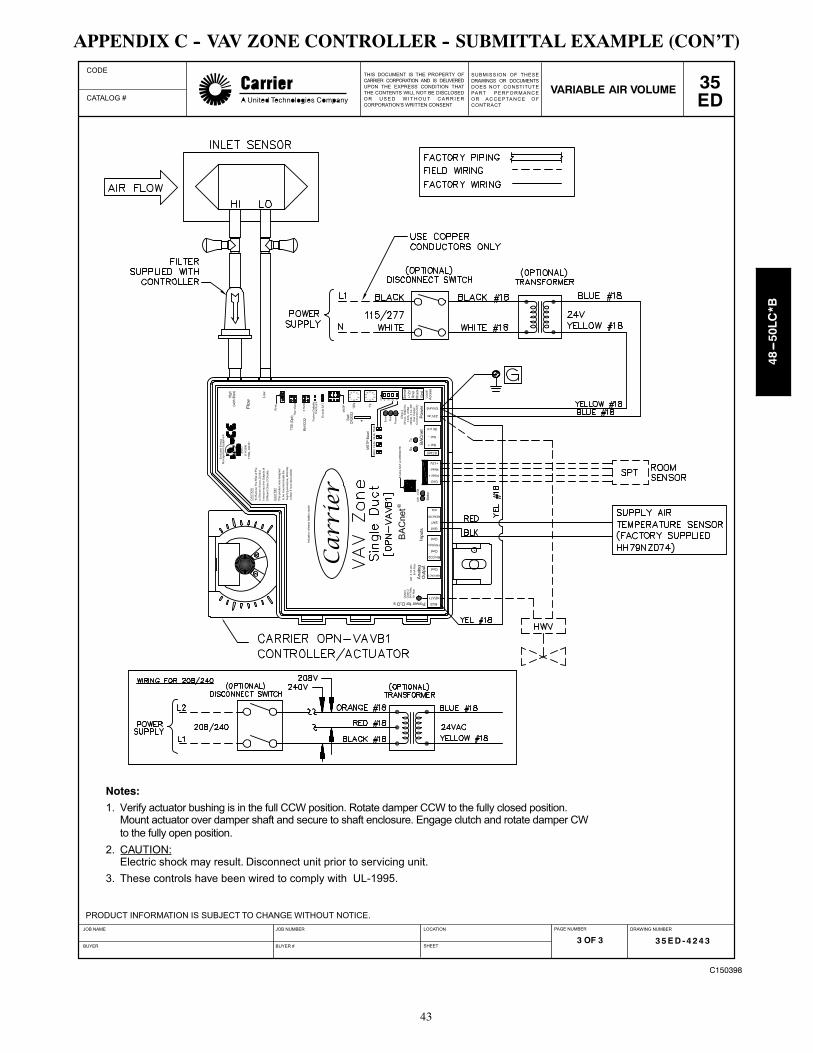
43
APPENDIX C -- VAV ZONE CONTROLLER -- SUBMITTAL EXAMPLE (CON’T)
CATALOG #
BUYER #
LOCATIONJOB NAME
SHEET
PAGE NUMBERJOB NUMBER
BUYER
DRAWING NUMBER
CODETHIS DOCUMENT IS THE PROPERTY OFCARRIER CORPORATION AND IS DELIVEREDUPON THE EXPRESS CONDITION THATTHE CONTENTS WILL NOT BE DISCLOSEDO R U S E D W I T H O U T C A R R I E RCORPORATION’S WRITTEN CONSENT
SUBMISSION OF THESEDRAWINGS OR DOCUMENTSDOES NOT CONSTITUTEPA RT P E R F O R M A N C EO R A C C E P TA N C E O FCONTRACT
3 5 E D - 4 2 4 3
PRODUCT INFORMATION IS SUBJECT TO CHANGE WITHOUT NOTICE.
VARIABLE AIR VOLUME 35ED
3 OF 3
Notes:
1. Verify actuator bushing is in the full CCW position. Rotate damper CCW to the fully closed position.Mount actuator over damper shaft and secure to shaft enclosure. Engage clutch and rotate damper CWto the fully open position.
2. CAUTION:Electric shock may result. Disconnect unit prior to servicing unit.
3. These controls have been wired to comply with UL-1995.
C150398
48---50LC*B
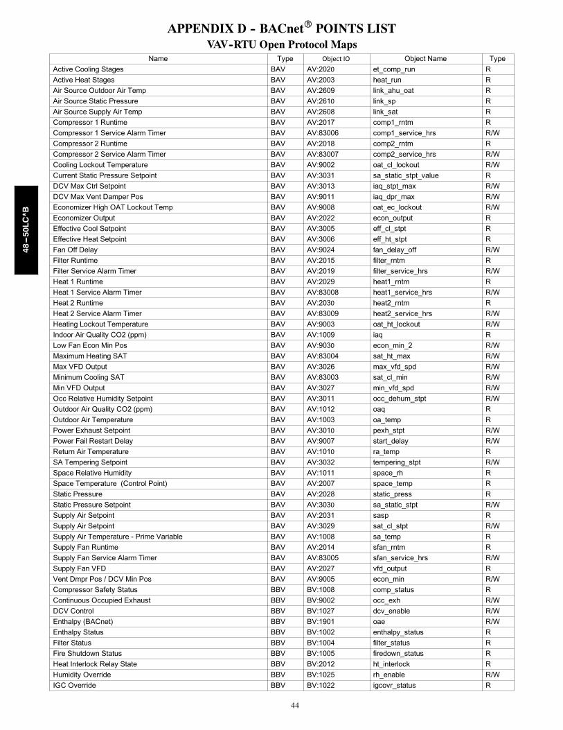
44
APPENDIX D -- BACnetR POINTS LISTVAV--RTU Open Protocol Maps
Name Type Object IO Object Name Type
Active Cooling Stages BAV AV:2020 et_comp_run R
Active Heat Stages BAV AV:2003 heat_run R
Air Source Outdoor Air Temp BAV AV:2609 link_ahu_oat R
Air Source Static Pressure BAV AV:2610 link_sp R
Air Source Supply Air Temp BAV AV:2608 link_sat R
Compressor 1 Runtime BAV AV:2017 comp1_rntm R
Compressor 1 Service Alarm Timer BAV AV:83006 comp1_service_hrs R/W
Compressor 2 Runtime BAV AV:2018 comp2_rntm R
Compressor 2 Service Alarm Timer BAV AV:83007 comp2_service_hrs R/W
Cooling Lockout Temperature BAV AV:9002 oat_cl_lockout R/W
Current Static Pressure Setpoint BAV AV:3031 sa_static_stpt_value R
DCV Max Ctrl Setpoint BAV AV:3013 iaq_stpt_max R/W
DCV Max Vent Damper Pos BAV AV:9011 iaq_dpr_max R/W
Economizer High OAT Lockout Temp BAV AV:9008 oat_ec_lockout R/W
Economizer Output BAV AV:2022 econ_output R
Effective Cool Setpoint BAV AV:3005 eff_cl_stpt R
Effective Heat Setpoint BAV AV:3006 eff_ht_stpt R
Fan Off Delay BAV AV:9024 fan_delay_off R/W
Filter Runtime BAV AV:2015 filter_rntm R
Filter Service Alarm Timer BAV AV:2019 filter_service_hrs R/W
Heat 1 Runtime BAV AV:2029 heat1_rntm R
Heat 1 Service Alarm Timer BAV AV:83008 heat1_service_hrs R/W
Heat 2 Runtime BAV AV:2030 heat2_rntm R
Heat 2 Service Alarm Timer BAV AV:83009 heat2_service_hrs R/W
Heating Lockout Temperature BAV AV:9003 oat_ht_lockout R/W
Indoor Air Quality CO2 (ppm) BAV AV:1009 iaq R
Low Fan Econ Min Pos BAV AV:9030 econ_min_2 R/W
Maximum Heating SAT BAV AV:83004 sat_ht_max R/W
Max VFD Output BAV AV:3026 max_vfd_spd R/W
Minimum Cooling SAT BAV AV:83003 sat_cl_min R/W
Min VFD Output BAV AV:3027 min_vfd_spd R/W
Occ Relative Humidity Setpoint BAV AV:3011 occ_dehum_stpt R/W
Outdoor Air Quality CO2 (ppm) BAV AV:1012 oaq R
Outdoor Air Temperature BAV AV:1003 oa_temp R
Power Exhaust Setpoint BAV AV:3010 pexh_stpt R/W
Power Fail Restart Delay BAV AV:9007 start_delay R/W
Return Air Temperature BAV AV:1010 ra_temp R
SA Tempering Setpoint BAV AV:3032 tempering_stpt R/W
Space Relative Humidity BAV AV:1011 space_rh R
Space Temperature (Control Point) BAV AV:2007 space_temp R
Static Pressure BAV AV:2028 static_press R
Static Pressure Setpoint BAV AV:3030 sa_static_stpt R/W
Supply Air Setpoint BAV AV:2031 sasp R
Supply Air Setpoint BAV AV:3029 sat_cl_stpt R/W
Supply Air Temperature - Prime Variable BAV AV:1008 sa_temp R
Supply Fan Runtime BAV AV:2014 sfan_rntm R
Supply Fan Service Alarm Timer BAV AV:83005 sfan_service_hrs R/W
Supply Fan VFD BAV AV:2027 vfd_output R
Vent Dmpr Pos / DCV Min Pos BAV AV:9005 econ_min R/W
Compressor Safety Status BBV BV:1008 comp_status R
Continuous Occupied Exhaust BBV BV:9002 occ_exh R/W
DCV Control BBV BV:1027 dcv_enable R/W
Enthalpy (BACnet) BBV BV:1901 oae R/W
Enthalpy Status BBV BV:1002 enthalpy_status R
Filter Status BBV BV:1004 filter_status R
Fire Shutdown Status BBV BV:1005 firedown_status R
Heat Interlock Relay State BBV BV:2012 ht_interlock R
Humidity Override BBV BV:1025 rh_enable R/W
IGC Override BBV BV:1022 igcovr_status R
48---50LC*B

45
APPENDIX D -- BACnetR POINTS LISTVAV--RTU Open Protocol Maps
Name Type Object IO Object Name Type
Occupancy Status BBV BV:2008 occ_status R
Occupied Heating BBV BV:2031 occ_heat R/W
Power Exhaust Relay State BBV BV:2010 pexh R
Reset Comp 1 Runtime Alarm BBV BV:7514 comp1_rntm_clr R/W
Reset Comp 2 Runtime Alarm BBV BV:7515 comp2_rntm_clr R/W
Reset Filter Alarm BBV BV:7517 filter_rntm_clr R/W
Reset Heat 1 Runtime Alarm BBV BV:7518 heat1_rntm_clr R/W
Reset Heat 2 Runtime Alarm BBV BV:7519 heat2_rntm_clr R/W
Reset Supply Fan Runtime Alarm BBV BV:7510 sfan_rntm_clr R/W
Safety Chain Feedback BBV BV:1009 safety_status R
Shutdown BBV BV:9001 shutdown R/W
Supply Fan Relay State BBV BV:2001 sfan R
Supply Fan Status BBV BV:1003 sfan_status R
System is shut down BBV BV:2011 shutdown_status R
Unocc Free Cool BBV BV:80001 ntfc_ena R/W
Air Source Mode BMSV MSV:2005 link_ahu_mode R
Equipment Status BMSV MSV:2001 mode_status R
Fan Mode BMSV MSV:9032 fan_mode R/W
SAT Reset Source BMSV MSV:2011 sat_reset_source R
Space Temp Source BMSV MSV:2003 spt_status R
System Mode BMSV MSV:2002 run_status R
Airside Linkage BALM BV:7030 air_linkage_fail R
Analog Input Configuration BALM BV:7026 ai_cfg_alarm R
Compressor 1 Runtime BALM BV:7014 comp1_rntm_alarm R
Compressor 2 Runtime BALM BV:7015 comp2_rntm_alarm R
Compressor Status BALM BV:7013 comp_alarm R
Economizer Operation BALM BV:7054 econ_opr R
Filter BALM BV:7017 filter_alarm R
Fire / Smoke Shutdown BALM BV:7007 fire_alarm R
Gas Valve BALM BV:7050 igc_alarm R
Heat 1 Runtime BALM BV:7062 heat1_rntm_alarm R
Heat 2 Runtime BALM BV:7063 heat2_rntm_alarm R
HPCO Shutdown BALM BV:7060 sp_alarm R
Indoor Air Quality BALM BV:7005 iaq_alarm R
Indoor Air Quality Sensor BALM BV:7039 iaq_sensor_fail R
Local OAT Sensor BALM BV:7003 loc_oat_sensor_fail R
Outdoor Air Quality Sensor BALM BV:7006 oaq_fail R
Outdoor Air Temp Sensor BALM BV:7029 oat_fail R
Return Air Temperature BALM BV:7035 rat_alarm R
Return Air Temp Sensor BALM BV:7052 rat_fail R
Safety Chain BALM BV:7024 safety_alarm R
Space Relative Humidity BALM BV:7018 sprh_hi_alarm R
Space Relative Humidity Sensor BALM BV:7022 sprh_sensor_fail R
Space Temp Sensor BALM BV:7001 spt_fail R
Static Pressure Sensor BALM BV:7061 sp_fail R
Supply Air Temperature BALM BV:7004 sat_alarm R
Supply Air Temp Sensor BALM BV:7020 loc_sat_sensor_fail R
Supply Fan Failure BALM BV:7008 sfan_fail_alarm R
Supply Fan in Hand BALM BV:7009 sfan_hand_alarm R
Supply Fan Runtime BALM BV:7010 sfan_rntm_alarm R
Switch Configuration BALM BV:7025 di_cfg_alarm R
ZS Sensor Configuration BALM BV:7055 zs_config_fail R
48---50LC*B

46
APPENDIX E -- EQUIPMENT/SYSTEM TOUCH NAVIGATION SCREENS
Equipment Touch is a touchscreen device with a 4.3 in.Color LCD display that can be connected to theVAV--RTU Open controller to view or change its propertyvalues, schedule equipment, view trends and alarms, andmore, without having to access the Building Automationsystem’s server.
C150399
Fig. 21 -- Equipment Touch
This appendix provides a brief overview of the screens usedto navigate the Equipment Touch. For full details oninstallation and setup refer to the Equipment TouchInstallation and Setup Guide.NOTE: The System Touch when connected to theVAV--RTU Open controller over the BACnet MS/TPnetwork will provide the same screens and function as theEquipment Touch.
Standby
C150400
The Standby screen displays after the Inactivity Timerexpires (default is 5 minutes).Displays:S Average space temperature
(optional Static Pressure or SAT)S current controlling setpointsS ModeS Occupancy statusS OAT, if available
The Standby screen is not interactive. Touch anywhere onthe screen to advance to the Home screen.
Home
C150401Displays:S Average space temperature
(optional Static Pressure or SAT)S Current controlling setpointsS ModeS Occupancy statusS OAT, if available
Click on the right to navigate to the Snapshot screen.
Snapshot
C150402Displays:S SAT, actual and setpointS RAT actualS Static Pressure, actual and setpointS % Open EconomizerS OAT actualS VFD % SpeedS Active Cooling StagesS Active Heating Stages
S Comp 1, Comp 2S Heat 1, Heat 2
S VAV--RTU Open alarms, if present
S Filter Status
Navigates to:
S Alarm status
S Trends
S Back to Home screen -- click on the left
S Forward to the VAV RTU Properties Menu screen--
click on the right
48---50LC*B
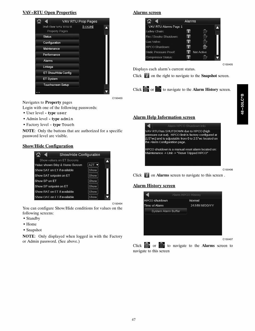
47
VAV--RTU Open Properties
C150403
Navigates to Property pagesLogin with one of the following passwords:S User level -- type userS Admin level -- type adminS Factory level -- type Touch
NOTE: Only the buttons that are authorized for a specificpassword level are visible.
Show/Hide Configuration
C150404
You can configure Show/Hide conditions for values on thefollowing screens:S StandbyS HomeS Snapshot
NOTE: Only displayed when logged in with the Factoryor Admin password. (See above.)
Alarms screen
C150405
Displays each alarm’s current status.
Click on the right to navigate to the Snapshot screen.
Click or to navigate to the Alarm History screen.
Alarm Help Information screen
C150406
Click on Alarms screen to navigate to this screen .
Alarm History screen
C150407
Click or to navigate to the Alarms screen tonavigate to this screen
48---50LC*B

48
Copyright 2015 Carrier Corp. D 7310 W. Morris St. D Indianapolis, IN 46231 Edition Date: 11/15
Manufacturer reserves the right to change, at any time, specifications and designs without notice and without obligations.
Catalog No: 48---50LCB---7---26---01T
Replaces: New
48---50LC*B

49
VAV--RTU OPEN START--UP SHEET
RTU Model Number: Date:
RTU Serial Number: Performed by:
VAV---RTU Open Software Version: Company:
Protocol and Baud Rate: Network Address:
CONFIGURATION POINTSPOINT NAME RANGE DEFAULT ENTRY
UNIT CONFIGURATION
Fan Mode 1 = Auto2 = Continuous3 = Always On
Continuous
Power Fail Restart Delay 0-30 sec 5
Fan Off Delay 5-120 sec 90
Occupied Heating Disable/Enable Disable
Supply Air Temp Reset Disable/Enable Disable
Reset Ratio 0-10 3
Reset Maximum Limit 0 - 25°F 10
Humidity Override Disable/Enable Disable
Minimum Cooling SAT1 45 - 75°F 45
Maximum Heating SAT 90 - 150°F 120
Vent Dmpr Pos / DCV Min Pos 0-100 % Open 20
Low Fan Econ Min Pos 0-100 % Open 33
DCV Max Vent Damper Pos 0-75 % Open 50
Static Pressure Reset Enable Disabled/Enabled Enabled
Maximum Damper Position 0-100 % Open 80
Minimum Damper Position 0-100 % Open 50
Maximum Reset 0.00 to 2.00 "wc 0.25
SP Reset Demand Level 1 = Not Active2 = Cool Dmd Lvl 13 = Cool Dmd Lvl 24 = Cool Dmd Lvl 3
Not Active
Supply Fan Service Alarm Timer 0-9999 hr 600
Comp 1 Service Alarm Timer 0-9999 hr 0
Comp 2 Service Alarm Timer 0-9999 hr 0
Filter Service Alarm Timer 0-9999 hr 600
Heat 1 Service Alarm Timer 0-9999 hr 0
Heat 2 Service Alarm Timer 0-9999 hr 0
Cooling Lockout Temperature -65 - 80°F 45
Economizer High OAT Lockout Temp 55 - 80°F 75
Heating Lockout Temperature 35 - 150°F 65
Unocc Free Cool Disable/Enable Disable
Min Setpoint Separation 2-10∆ °F 5∆
1 Default to meet California Title 24 requirements is 45°F48---50LC*B
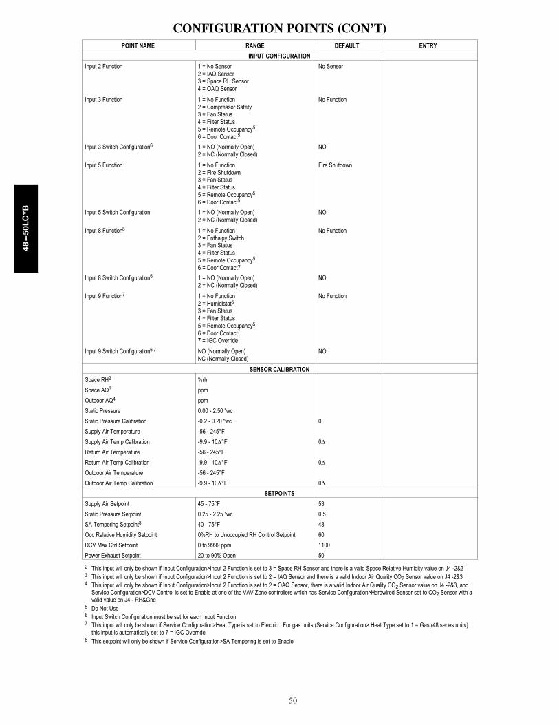
50
CONFIGURATION POINTS (CON’T)POINT NAME RANGE DEFAULT ENTRY
INPUT CONFIGURATION
Input 2 Function 1 = No Sensor2 = IAQ Sensor3 = Space RH Sensor4 = OAQ Sensor
No Sensor
Input 3 Function 1 = No Function2 = Compressor Safety3 = Fan Status4 = Filter Status5 = Remote Occupancy5
6 = Door Contact5
No Function
Input 3 Switch Configuration6 1 = NO (Normally Open)2 = NC (Normally Closed)
NO
Input 5 Function 1 = No Function2 = Fire Shutdown3 = Fan Status4 = Filter Status5 = Remote Occupancy5
6 = Door Contact5
Fire Shutdown
Input 5 Switch Configuration 1 = NO (Normally Open)2 = NC (Normally Closed)
NO
Input 8 Function8 1 = No Function2 = Enthalpy Switch3 = Fan Status4 = Filter Status5 = Remote Occupancy5
6 = Door Contact7
No Function
Input 8 Switch Configuration6 1 = NO (Normally Open)2 = NC (Normally Closed)
NO
Input 9 Function7 1 = No Function2 = Humidistat5
3 = Fan Status4 = Filter Status5 = Remote Occupancy5
6 = Door Contact7
7 = IGC Override
No Function
Input 9 Switch Configuration6 7 NO (Normally Open)NC (Normally Closed)
NO
SENSOR CALIBRATION
Space RH2 %rh
Space AQ3 ppm
Outdoor AQ4 ppm
Static Pressure 0.00 - 2.50 "wc
Static Pressure Calibration -0.2 - 0.20 "wc 0
Supply Air Temperature -56 - 245°F
Supply Air Temp Calibration -9.9 - 10∆°F 0∆
Return Air Temperature -56 - 245°F
Return Air Temp Calibration -9.9 - 10∆°F 0∆
Outdoor Air Temperature -56 - 245°F
Outdoor Air Temp Calibration -9.9 - 10∆°F 0∆
SETPOINTS
Supply Air Setpoint 45 - 75°F 53
Static Pressure Setpoint 0.25 - 2.25 "wc 0.5
SA Tempering Setpoint8 40 - 75°F 48
Occ Relative Humidity Setpoint 0%RH to Unoccupied RH Control Setpoint 60
DCV Max Ctrl Setpoint 0 to 9999 ppm 1100
Power Exhaust Setpoint 20 to 90% Open 50
2 This input will only be shown if Input Configuration>Input 2 Function is set to 3 = Space RH Sensor and there is a valid Space Relative Humidity value on J4 -2&33 This input will only be shown if Input Configuration>Input 2 Function is set to 2 = IAQ Sensor and there is a valid Indoor Air Quality CO2 Sensor value on J4 -2&34 This input will only be shown if Input Configuration>Input 2 Function is set to 2 = OAQ Sensor, there is a valid Indoor Air Quality CO2 Sensor value on J4 -2&3, and
Service Configuration>DCV Control is set to Enable at one of the VAV Zone controllers which has Service Configuration>Hardwired Sensor set to CO2 Sensor with avalid value on J4 - RH&Gnd
5 Do Not Use6 Input Switch Configuration must be set for each Input Function7 This input will only be shown if Service Configuration>Heat Type is set to Electric. For gas units (Service Configuration> Heat Type set to 1 = Gas (48 series units)
this input is automatically set to 7 = IGC Override8 This setpoint will only be shown if Service Configuration>SA Tempering is set to Enable
48---50LC*B

51
CONFIGURATION POINTS (CON’T)POINT NAME RANGE DEFAULT ENTRY
ALARM CONFIGURATION
SP High Limit Trip Setpoint 0 to 2.50 "wc 1.50
Low SAT Alarm Limit 15-90°F 38
High SAT Alarm Limit 90-175°F 160
Low RAT Alarm Limit 15-90°F 38
High RAT Alarm Limit 90-175°F 120
Occupied High RH Alarm Limit 0-100%RH 70
Alarm Delay (min/%RH) 0-30 min 5
Unoccupied High RH Alarm Limit 0-100%rh 100
Low RH Alarm Limit 0-100%rh 30
Occ High CO2 Alarm Limit 0-9999 ppm 1200
SERVICE CONFIGURATION
Compressor Stages9 N/A Three Stages
Economizer Exists10 N/A Yes (FIOP)
VFD Input 0-10Vdc/2-10Vdc 2-10Vdc
Max VFD Output 15-100% 100
Min VFD Output 15-100% 25
Heat Type 0 = Electric (50 series units)1 = Gas (48 series units)
Gas
Number of Heat Stages 1 = 1 stage (All 50LC*B07-09 units,50LC*B12-14 lo heat)
2 = 2 stages (All 48LC*B07-26 units,50LC*B12 hi heat, 50LC*B14 med/hi heat,All 50LC*B17-26 units)
2
SA Tempering Disabled/Enabled Disable
Continuous Occupied Exhaust No/Yes No
DCV Control Disable/Enable Disable
Indoor CO2 Sensor Value @ Min mA11 0-9999ppm 0
Indoor CO2 Sensor Value @ Max mA11 0-9999ppm 2000
Outdoor CO2 Sensor Value @ Min mA12 0-9999ppm 0
Outdoor CO2 Sensor Value @ Max mA12 0-9999ppm 2000
Static Pressure Sensor Value @ Min mA 0
Static Pressure Sensor Value @ Max mA 2.5
System Space RH N/A -999.0
System Space AQ N/A -999.0
System Cool Demand Level 0-3 0
System Heat Demand Level 0-3 0
System Outdoor Air Temperature N/A -999.0
System Outdoor AQ N/A -999.0
System Fire / Smoke Off/On Off
SERVICE TEST
Service Test Mode Disable/Enable
Service Test Disable/Enable Disable
Fan Test Disable/Enable Disable
Compressor 1 Test Disable/Enable Disable
Compressor 2 Test Disable/Enable Disable
Heat 1 Test Disable/Enable Disable
Heat 2 Test Disable/Enable Disable
Heat Interlock Relay Test Disable/Enable Disable
Power Exhaust Test Disable/Enable Disable
Economizer Test 0-100 %Open 0
VFD Speed Test 0-100% 0
9 Compressor Stages default is Three Stages and cannot be changed10 Economizer Exist default is Yes and cannot be changed11 This configuration will only be shown if Input Configuration>Input 2 Function is set to 2 = IAQ Sensor12 This configuration will only be shown if Input Configuration>Input 2 Function is set to 4 = OAQ Sensor
48---50LC*B

52
VAV ZONE AIRSIDE LINKAGE CONFIGURATIONEquipment Touch orSystem Touch Menu POINT NAME RANGE ENTRY
AIRSIDE LINKAGE
Air TerminalProperties>Startup Wizard>Airside Linkage Configuration
Linkage CollectorIf Master zone, set Number of Providersto the total # of controllers that will reportto the Master, including the masterFor a slave zone the # of providers is 1
1 to 64
Linkage ProviderIf Master zone, set MS/TP networknumber and MAC address of the RTU(air source) with the VAV-RTU OpencontrollerFor a slave zone leave at zero
Network Number:0 to 65,535
MAC Address:0 to 127
Airside Linkage Status Active/Not Active
Linkage Zone Type SlaveVVT MasterVAV Master
Inhibit Heating Call from this zone? No/Yes
Active Heating Caller? No/Yes
Inhibit Cooling Call from this zone? No/Yes
Active Cooling Caller? No/Yes
Linkage RH Type Avg/Max
Linkage IAQ Type Avg/Max
Air Source Mode OffWarmupHeatCoolFreecoolPressureEvacVent
Air Source Supply Air Temp °F
Air Source Static Pressure in wc
Air Source Outdoor Air Temp °F
Number of ProvidersIf Master zone, set Number of Providersto the total # of controllers that will report
to the Master, including the masterFor a slave zone the # of providers is 1
1 to 64
Air Terminal Properties>Startup Wizard>Airside Linkage Configuration>Air Source Configuration
Air Source (RTU)(Collector) Network # 0 to 65,535
Air Source Address Type MSTP or IP
MS/TP Address 0 to 137
Copyright 2015 Carrier Corp. D 7310 W. Morris St. D Indianapolis, IN 46231 Edition Date: 11/15
Manufacturer reserves the right to change, at any time, specifications and designs without notice and without obligations.
Catalog No: 48---50LCB---7---26---01T
Replaces: New
48---50LC*B