copyright © 2001 - 2008 keyscan inc. all rights reserved.€¦ · table 4 – ocb-8 to ec 2200...
TRANSCRIPT


Copyright © 2001 - 2008 Keyscan Inc. All rights reserved. Information in this document is subject to change without notice. Except for the benefit of installation and operation of the Keyscan access control system, no part of this documentation may be reproduced or transmitted in any form or by any means without the expressed written permission of Keyscan Inc. Keyscan Inc. 901 Burns Street East Whitby, Ontario Canada L1N 6A6 Phone: 1-888-539-7226 (Toll Free Canada/USA) Phone: 905-430-7226 Fax: 905-430-7275 Web Site: www.keyscan.ca

Keyscan Technical Guide (Rev. 11 / 04.08) 1
Table of Contents List of Figures ....................................................................................................................................3
List of Tables .....................................................................................................................................7
Foreword ...........................................................................................................................................9
Requirements ..................................................................................................................................10
General Installation Guidelines........................................................................................................14
Mounting ACUs/Circuit Boards/Power Supplies ..............................................................................16
Mounting Readers & Door Hardware...............................................................................................25
Terminate Wiring at the ACU...........................................................................................................29
ACU/ECU Jumper Settings..............................................................................................................50
Communication – Single & Multiple ACUs.......................................................................................61
Power-up and Test Voltages ...........................................................................................................98
Appendix A – HID Reader Connections ........................................................................................105
Appendix B – Indala Reader Connections.....................................................................................119
Appendix C – Keyscan WSSKP1 Connections..............................................................................124
Appendix D – RXPROX Receiver / Transmitter Activation ............................................................127
Appendix E – Keyscan COMMex ..................................................................................................130
Appendix F – Wiegand Extenders WIEEX and CWIEEX...............................................................133
Appendix G – Handicap Accessibility Relay Option.......................................................................139
Appendix H – Pre-alert Relay Option.............................................................................................143
Appendix I – MISCOMM2 Communication between Buildings on a CPB-10 Loop........................147
Appendix J – Telephone Entry Systems........................................................................................152
Appendix K – 'MISC-BRC' Barcode Reader Interface ...................................................................156
CA 230 Quick Reference...............................................................................................................158
CA 4300 Quick Reference.............................................................................................................162
CA 8300 Quick Reference.............................................................................................................166
EC 1300 Quick Reference.............................................................................................................170
EC 2300 Quick Reference.............................................................................................................174
Relay States ..................................................................................................................................177

Keyscan Technical Guide (Rev. 11 / 04.08) 2
Warranty........................................................................................................................................179
Index..............................................................................................................................................180

Keyscan Technical Guide (Rev. 11 / 04.08) 3
List of Figures Figure 1 - Grounding Access Control Units and Cables with CB-485s ............................................12 Figure 2 - Grounding Access Control Units and Cables with CPB-10s............................................13 Figure 3 - Mounting the Access Control Panel ................................................................................17 Figure 4 - Stand Off .........................................................................................................................17 Figure 5 - Mounting Power Supplies................................................................................................19 Figure 6 - CA 200 with Circuit Board Mounting Positions ................................................................20 Figure 7 - CA 4000 with Circuit Board Mounting Positions ..............................................................20 Figure 8 - CA 8000 with Circuit Board Mounting Positions ..............................................................21 Figure 9 - EC 1000 with Circuit Board Mounting Positions ..............................................................21 Figure 10 - EC 2000 with Circuit Board Mounting Positions ............................................................22 Figure 11 - Securing the Enclosure Cover.......................................................................................23 Figure 12 – Typical Door Layout......................................................................................................25 Figure 13 - Typical Door Strike Connection.....................................................................................26 Figure 14 - Typical Door Maglock Connection.................................................................................26 Figure 15 - Door Contacts, Exit Buttons, PIRs, & Auxiliary Inputs ...................................................27 Figure 16 - Door Reader Connection...............................................................................................28 Figure 17 - Lock State - Fail Safe Device ........................................................................................30 Figure 18 - Lock State - Fail Secure Device ....................................................................................31 Figure 19 - Terminate Lock Wiring CA 230 .....................................................................................32 Figure 20 - Terminate Lock Wiring CA 4300 ...................................................................................33 Figure 21 - Terminate Lock Wiring CA 8300 ...................................................................................34 Figure 22 - Terminate Input Wiring – Door Contacts CA 230 / CA 4300 / CA 8300.........................36 Figure 23 - Terminate Input Wiring – RTE Push Button CA 230 / CA 4300 / CA 8300....................37 Figure 24 - Terminate Input Wiring – RTE PIR Motion Sensor CA 230 / CA 4300 / CA 8300 .........38 Figure 25 - Terminate Input Wiring – Auxiliary/Supervised Inputs CA 230 / CA 4300 / CA 8300 ....39 Figure 26 - Terminate Floor Wiring EC 1300...................................................................................41 Figure 27 - Terminate Floor Wiring EC 2300...................................................................................42 Figure 28 - Terminate Floor Input Wiring EC 1300 ..........................................................................43 Figure 29 - Terminate Floor Input Wiring EC 2300 ..........................................................................44
Keyscan Technical Guide (Rev. 11 / 04.08) 4
Figure 30 - Terminate Reader Wiring ..............................................................................................45 Figure 31 - Terminate Auxiliary Outputs CA 230 .............................................................................47 Figure 32 - Terminate Auxiliary Outputs CA 4300 ...........................................................................48 Figure 33 - Terminate Auxiliary Output CA 8300 .............................................................................49 Figure 34 - System Jumper J16.......................................................................................................50 Figure 35 - System Jumper J16 Location on ACU/ECU Circuit Boards...........................................52 Figure 36 - Software Jumper J17 ....................................................................................................53 Figure 37 - Software Jumper J17 Location on CA & EC boards......................................................53 Figure 38 - Reader Type Jumper J3................................................................................................54 Figure 39 - Reader Format Jumper J3 and Wiegand Bit Counter LEDs..........................................56 Figure 40 - Address/External Jumper J18 .......................................................................................59 Figure 41 - Jumper J18 Location – CA 230 / CA 4300 / CA 8300 ...................................................59 Figure 42 - Clear Memory Jumper J1 - All CA & EC boards............................................................60 Figure 43 - Single ACU Communication - Direct Serial ...................................................................63 Figure 44 - Single ACU Communication – Serial CB-485................................................................64 Figure 45 - Single ACU Communication - Serial CPB-10 ................................................................65 Figure 46 – Single ACU Communication - USB Adaptor .................................................................66 Figure 47 - Single ACU Communication - USB Adaptor/CB-485 (RS232) ......................................67 Figure 48 - Single ACU Communication - USB Adaptor/CB-485 (RS485) ......................................68 Figure 49 - Single ACU Communication - USB Adaptor/CPB-10 (RS232) ......................................69 Figure 50 - Single ACU Communication - NETCOM2P or NETCOM6P/CB-485.............................70 Figure 51 - NETCOM2 or NETCOM6/CB-485.................................................................................71 Figure 52 - Single ACU Communication - NETCOM2 or NETCOM6...............................................72 Figure 53 - Single ACU Communication - NETCOM2 or NETCOM6/CPB-10 .................................73 Figure 54 - Single ACU Communication NETCOM2WH or NETCOM 6WH / CB-485.....................74 Figure 55 - Single ACU Communication - NETCOM2WH or NETCOM6WH / CPB-10 ...................75 Figure 56 - Single ACU Communication - NETCOM2WH or NETCOM6WH / ACU ........................76 Figure 57 - Single ACU Communication - CB-485M/MC33H ..........................................................77 Figure 58 - Single ACU Communication - MC9600/MC33H ............................................................78 Figure 59 - Single ACU Communication - MC9600/MC33H/CPB-10...............................................79 Figure 60 – Multiple ACU Communication – CB-485.......................................................................81 Figure 61 – Multiple ACU Communication – CPB-10 ......................................................................82 Figure 62 – Multiple ACU Communication – USB Adaptor/CB-485 (RS-232) .................................83
Keyscan Technical Guide (Rev. 11 / 04.08) 5
Figure 63 - Multiple ACU Communication - USB Adaptor/CB-485 (RS-485)...................................84 Figure 64 - Multiple ACU Communication - USB Adaptor/CPB-10 ..................................................85 Figure 65 - Multiple ACU Communication - NETCOM2P or NETCOM6P/CB-485 ..........................86 Figure 66 - Multiple ACU Communication - NETCOM2 or NETCOM6/CPB-10...............................87 Figure 67 - Multiple ACU Communication - NETCOM2P or NETCOM6P/CB-485 (1 to 1) ..............88 Figure 68 - Multiple ACU Communication - NETCOM2 or NETCOM6 (1 per ACU) ........................89 Figure 69 - Multiple ACU Communication - NETCOM2WH or NETCOM6WH/CB-485s .................90 Figure 70 - Multiple ACU Communication - NETCOM2WH or NETCOM6WH/CPB-10s .................91 Figure 71 - Multiple ACU Communication - NETCOM2WH or NETCOM6WH / 1 per ACU.............92 Figure 72 - Multiple ACU Communication - CB-485M/CB-485/MC33H...........................................93 Figure 73 - Multiple ACU Communication - MC9600/CPB-10/MC33H ............................................94 Figure 74 - Communication LEDs CA & EC boards ........................................................................97 Figure 75 - Communication LEDs on CB-485..................................................................................97 Figure 76 - Communication LEDs on CPB-10 .................................................................................97 Figure 77 - Power Supply Wiring .....................................................................................................99 Figure 78 - Controller Test Points – Voltages................................................................................101 Figure 79 – ACU Communication Test Points ...............................................................................103 Figure 80 - CB-485 Communication Test Points ...........................................................................103 Figure 81 - CPB-10 Communication Test Points ...........................................................................104 Figure 82 - Keyscan K-PROX2 (125 KHz HID compatible) ...........................................................107 Figure 83 - Keyscan K-VAN Proximity Reader (125 KHz HID compatible)....................................108 Figure 84 - Keyscan K-KPR Keypad / Proximity Reader (125 KHz HID compatible).....................109 Figure 85 - HID-5395 Wiring..........................................................................................................110 Figure 86 - HID 5365 / 6005 Wiring ...............................................................................................111 Figure 87 - HID 5355 Wiring ..........................................................................................................112 Figure 88 - HID 5375 Wiring ..........................................................................................................113 Figure 89 - HID 5355KP Wiring .....................................................................................................114 Figure 90 - HID iClass KEYR10.....................................................................................................115 Figure 91 - HID iClass KEYR40.....................................................................................................116 Figure 92 - HID iClass KEYRW400 ...............................................................................................117 Figure 93 - HID iClass KEYRK40 ..................................................................................................118 Figure 94 - Indala PX 603 and PX 605 Wiring ...............................................................................120 Figure 95 - Indala PX610 Wiring....................................................................................................121
Keyscan Technical Guide (Rev. 11 / 04.08) 6
Figure 96 – Indala PX 620 Wiring..................................................................................................122 Figure 97 - Indala PXK 501 Wiring ................................................................................................123 Figure 98 - WSSKP-1 Keypad Connection....................................................................................125 Figure 99 - WSSKP-1 Keypad/Reader Combination Connections ................................................126 Figure 100 - RXPROX Receiver Connections ...............................................................................129 Figure 101 - COMMex Overview ...................................................................................................131 Figure 102 - COMMex Connections ..............................................................................................132 Figure 103 - Wiegand Extender Overview.....................................................................................135 Figure 104 - WIEEX RS485 Transmitter/Receiver Connections....................................................136 Figure 105 - CWIEEX - Coaxial Transmitter/Receiver Connections ..............................................137 Figure 106 - WIEEX to OCB-8 Cable Connection .........................................................................138 Figure 107 - Handicap Relay CA 230/OCB-8 Connections ...........................................................140 Figure 108 - Handicap Relay CA 4300/OCB-8 Connections .........................................................141 Figure 109 - Handicap Relay CA 8300/OCB-8 Connections .........................................................142 Figure 110 - Pre-alert Relay CA 230/OCB-8 Connections.............................................................144 Figure 111 - Pre-alert Relay CA 4300/OCB-8 Connections...........................................................145 Figure 112 - Pre-alert Relay CA 8300/OCB-8 Connections...........................................................146 Figure 113 - MISCOMM2 – Inter Building Communication to a single ACU ..................................148 Figure 114 - MISCOMM2 Connections – to a single ACU.............................................................149 Figure 115 - MISCOMM2 Inter Building Communication to Multiple ACUs ...................................150 Figure 116 - MISCOMM2 Connections to Multiple ACUs ..............................................................151 Figure 117 - VIS100 - ENT Connections .......................................................................................153 Figure 118 - VIS100 SES Connections .........................................................................................154 Figure 119 - VIS100 STX Connections..........................................................................................155 Figure 120 - Bar Code Card Placement Specifications .................................................................156 Figure 121 - MISC-BRC Barcode Reader Interface Connections..................................................157 Figure 122 - CA 230 Circuit Board.................................................................................................158 Figure 123 - CA 4300 Circuit Board...............................................................................................162 Figure 124 - CA 8300 Circuit Board...............................................................................................166 Figure 125 - EC 1300 Circuit Board...............................................................................................170 Figure 126 - EC 2300 Circuit Board...............................................................................................174

Keyscan Technical Guide (Rev. 11 / 04.08) 7
List of Tables Table 1 - Cable Requirements.........................................................................................................11 Table 2 - Battery Duration Times.....................................................................................................18 Table 3 – OCB-8 to EC 1300 Ribbon Cable Connections ...............................................................40 Table 4 – OCB-8 to EC 2200 Ribbon Cable Connections ...............................................................40 Table 5 - System Jumper J16 Settings............................................................................................50 Table 6 - Software Jumper J17........................................................................................................53 Table 7 - Reader Type Jumper J3 ...................................................................................................54 Table 8 - J18 Jumper Settings.........................................................................................................59 Table 9 - Single ACU Communication .............................................................................................62 Table 10 - Multiple ACU Communication.........................................................................................80 Table 11 - Communication LEDs.....................................................................................................96 Table 12 - Controller Test Points - Voltages..................................................................................100 Table 13 – Communication Voltage Test Points............................................................................102 Table 14 - HID Reader Power Specifications ................................................................................105 Table 15 - Indala Reader Power Specifications.............................................................................119 Table 16 - Keypad Power Specifications .......................................................................................124 Table 17 - RXPROX (RF) Receiver Specifications ........................................................................127 Table 18 - COMMex Power Specifications ....................................................................................130 Table 19 - COMMex Communication and Cables .........................................................................130 Table 20 - WIEEX/CWIEEX Power Requirements ........................................................................133 Table 21 - WIEEX/CWIEEX Cables and Distances .......................................................................133 Table 22 - OCB8 Power Specifications .........................................................................................139 Table 23 - Handicap Relay/ Door Assignment...............................................................................139 Table 24 – OCB-8 Power Specifications .......................................................................................143 Table 25 - Pre-alert Relay to Door Assignments ...........................................................................143 Table 26 - MISCOMM2 Voltages...................................................................................................147 Table 27 - CA 230 Quick Reference..............................................................................................159 Table 28 - CA 4300 Quick Reference............................................................................................163 Table 29 - CA 8300 Quick Reference............................................................................................167

Keyscan Technical Guide (Rev. 11 / 04.08) 8
Table 30 - EC 1300 Quick Reference............................................................................................171 Table 31 - EC 2300 Quick Reference............................................................................................175 Table 32 – List of Relay States......................................................................................................177

Keyscan Technical Guide (Rev. 11 / 04.08) 9
Foreword Keyscan systems are designed for use in various environments and applications. As such, care must be exercised to ensure proper cable, power, ground, and environment specifications are followed for reliable and safe operation of the equipment.
Approved Standards Keyscan CA 200, CA 4000 and CA 8000 access control units conform to the following approved standards:
• UL STD 294 – Access Control Systems Units • CSA STD C22.2 No. 205-M1983 – Signal Equipment
Product Listings The certification record can be viewed at http://directories.csa-international.org.
Enter 110441_0_000 in the File Number box.
About This Guide This Technical Guide is designed to provide general information for installing Keyscan access control systems. This guide assumes the installer has knowledge of electrical, electronic, mechanical, and computer concepts, as well as having familiarity with access control systems and associated components. The guide is divided into 4 sections:
• Requirements • Installation Guidelines • Mounting and Connecting System Components • Appendices
We have tried to organize the technical guide in a manner that allows for quick referencing based on installation tasks with pertinent diagrams.

Keyscan Technical Guide (Rev. 11 / 04.08) 10
Requirements The following is a review of power, cable, and ground requirements for the access control system.
Power Each access control unit requires two dedicated Class 2 transformers. The following transformers are acceptable:
• 16V 40VA transformer • 16.5V 37VA transformer
Any deviation from a specified transformer or the use of a single transformer to power multiple access control units will cause faulty system operation. All warranties are voided if non CLASS 2 transformers or incorrect voltages are used.
Standby batteries with their duration times for access control and reader power are listed on page 18.
Important The power supply included with each access control unit is for the exclusive use of the ACU circuit boards and the readers. It should not be used to power external devices such as door strikes or magnetic locks.
Electrical Precautions Be sure that all circuit breakers powering the system are switched off before commencing installation or modifying wiring connections. Do not apply power before the installation is completed otherwise damage to the equipment may result. Connect earth grounds to all enclosures ensuring proper and safe operation of the system.
Tools We recommend having the following tools on hand to complete the installation of the access control system:
• Digital Voltmeter • Wire Cutters & Needle Nose Pliers • Soldering Iron & Tape • Set of Screwdrivers • Drill & Drill Bits • Laptop Computer (optional)

Keyscan Technical Guide (Rev. 11 / 04.08) 11
Cables The following table outlines system cable requirements. Please be sure to review grounding guidelines for safe system operation. Avoid running access control system cables parallel with AC wires or across florescent light fixtures. This can cause AC induction or transmission interference.
Table 1 - Cable Requirements
Standard Device Wiring Signal Protocol
Maximum Distance
Cable Type Notes
Readers to ACU (includes HID iClass – Rev B)
Wiegand 500 ft 152.4 m
3 pairs shielded 22AWG
Overall shielded cable accepted. CAT5 cable not acceptable with Wiegand signal protocol.
Exception Readers to ACU – PX-620, HID-5375, MR-10, MR-20, HID-iClass (Rev A), and elevator readers
Wiegand 500 ft 152.4 m
3 pairs shielded 18AWG
Overall shielded cable accepted. CAT5 cable not acceptable with Wiegand signal protocol.
Door Strikes & Electro Magnets to ACU
n/a 500 ft 152.4 m
1 pair 18AWG Shielded wire not required.
Contacts & Exit Devices n/a 500 ft 152.4 m
1 pair 22AWG Shielded wire not required.
Motion Sensors (PIR) n/a 500 ft 152.4 m
2 pairs 22AWG Shielded wire not required
CB-485 RS485 2000 ft 609 m
CAT5 – 2 twisted pairs
Maximum distance @ 9600 BPS between units Maximum baud rate is 56K BPS
CB-485M RS485 2000 ft 609 m
CAT5 – 3 twisted pairs
Maximum distance @ 9600 BPS between units Maximum baud rate is 19.2K BPS
CPB-10 (9600 baud) Not recommended for use with Rev. 11 boards.
EIA/TIA-562 2000 ft 609 m
4 conductors shielded 22AWG
Overall shielded cable accepted. CAT5 cable not acceptable with EIA/TIA-562 signal protocol. Maximum distance between units. Overall maximum is 4000 ft (1219.2 m)
CPB-10 (19200 baud) Not recommended for use with Rev. 11 boards.
EIA/TIA-562 200 ft 61 m
4 conductors shielded 22AWG
Overall shielded cable accepted. CAT5 cable not acceptable with EIA/TIA-562 signal protocol. Maximum between units and overall distance.
ACU/PC/Modem/CB-485/ NETCOM/CPB-10
RS-232 (9600 BPS)
100 ft 30 m
5 conductors shielded 22AWG
Overall shielded cable accepted. CAT5 cable not acceptable with RS-232 signal protocol.
COMMEX Extender Kit (PC Extender)
n/a 4000 ft 1219.2 m
CAT 5 - 2 twisted pairs communication
Shielded wire not required. Kit includes 1 transmitter & 1 receiver.
WIEEX Extender Kit (Wiegand Protocol Extender)
n/a 4000 ft 1219.2 m
CAT 5 – 1 twisted pair communication. 1 pair 18AWG power to TX.
If powering transmitter locally, 18 AWG power wiring is not required. Kit includes 1 transmitter & 1 receiver.
CWIEEX Extender Kit (Coax Extender)
n/a 500 ft 152.4 m
RG59U Coax cable required. Kit includes 1 transmitter & 1 receiver.
Keyscan Technical Guide (Rev. 11 / 04.08) 12
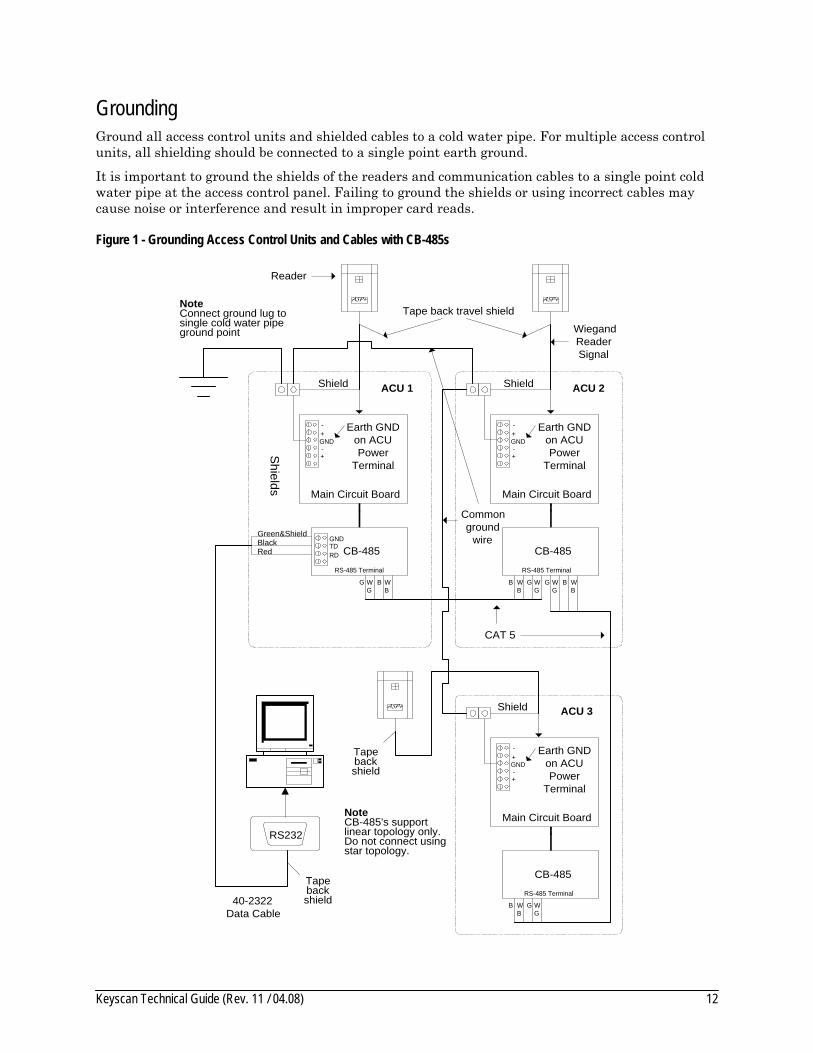
Grounding Ground all access control units and shielded cables to a cold water pipe. For multiple access control units, all shielding should be connected to a single point earth ground.
It is important to ground the shields of the readers and communication cables to a single point cold water pipe at the access control panel. Failing to ground the shields or using incorrect cables may cause noise or interference and result in improper card reads.
Figure 1 - Grounding Access Control Units and Cables with CB-485s
40-2322Data Cable
NoteConnect ground lug tosingle cold water pipeground point
Tapebackshield
ASP+
Reader
Tapebackshield
CAT 5
WiegandReaderSignal
Shields
Commonground
wire
Tape back travel shieldASP+
ASP+
CB-485
ACU 1
Earth GNDon ACUPower
Terminal
CB-485
CB-485
RS232
Main Circuit Board
ACU 3
Main Circuit Board
Main Circuit Board
ACU 2Shield Shield
Shield
GND+-
+-
Earth GNDon ACUPower
Terminal
GND+-
+-
Earth GNDon ACUPower
Terminal
GND+-
+-
GNDTDRD
Green&ShieldBlackRed
G WG
B WB
G WG
B WB
B WB
G WG
B WB
G WG
RS-485 Terminal RS-485 Terminal
RS-485 Terminal
NoteCB-485's supportlinear topology only.Do not connect usingstar topology.
Keyscan Technical Guide (Rev. 11 / 04.08) 13
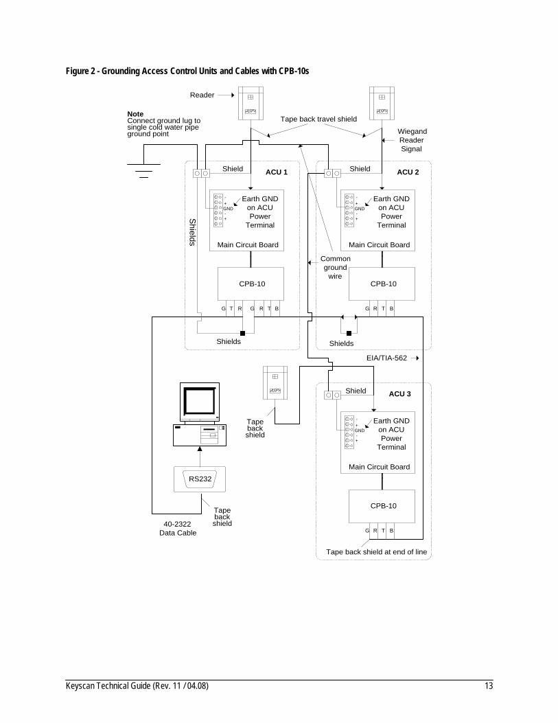
Figure 2 - Grounding Access Control Units and Cables with CPB-10s
40-2322Data Cable
NoteConnect ground lug tosingle cold water pipeground point
Shields
Tapebackshield
Tape back shield at end of line
ASP+
Reader
Tapebackshield
EIA/TIA-562
WiegandReaderSignal
Shields
Commonground
wire
Tape back travel shieldASP+
ASP+
CPB-10
ACU 1
Earth GNDon ACUPower
Terminal
G R T BG RT
CPB-10
BG R T
CPB-10
BG R T
RS232
Shields
Main Circuit Board
ACU 3
Main Circuit Board
Main Circuit Board
ACU 2Shield Shield
Shield
GND+-
+-
Earth GNDon ACUPower
Terminal
GND+-
+-
Earth GNDon ACUPower
Terminal
GND+-
+-

Keyscan Technical Guide (Rev. 11 / 04.08) 14
General Installation Guidelines
Mounting Access Control Units and Components Identify and mount all hardware including access control units and power supplies in a convenient and suitable location. Do not mount access control units close to high voltage equipment. Comply with all local and regional codes.
Each access control unit requires two dedicated Class 2 transformers. The following transformers are acceptable:
• 16V 40VA transformer • 16.5V 37VA transformer
Record the serial number and the model number listed on the ACU's main circuit board. The serial number is a required entry in the Client software.
Mounting Readers and Door Hardware Install all door hardware. Be sure to position readers on the door latch side and at a convenient height. Using a battery for power, ensure the door operates properly – alignment, holding, activation, de-activation – before connecting to the Keyscan access control unit. Where applicable, comply with all fire and safety codes for the installation of door strikes and magnetic locks.
If a door/reader is located beyond the maximum cable length to the ACU, use a Keyscan WIEEX Extender Kit to a maximum distance of 4000 feet (1219.2 m).
Cables Run all cables between components. Label cables as they are installed. Do not connect cables at the ACU until all hardware has been tested and is operating correctly. Cable routes should avoid potential sources of electrical noise from fluorescent light fixtures, high voltage equipment, high voltage lines, and radio transmission equipment that may impede access control system communications.
Be sure to comply with proper cable types and do not exceed maximum distances.
Elevators Elevator installations require licensed 3rd party technicians. Not all readers operate properly in elevators. Use suitable readers.
Terminate Wiring at the ACU Terminate reader, lock, input, elevator floor, and elevator input wiring to the designated input terminals on the appropriate ACU circuit boards.

Keyscan Technical Guide (Rev. 11 / 04.08) 15
All Keyscan circuit board relays use Form C contacts rated at 5 Amps, 24VAC or 32VDC maximum.
Use a separate power supply for door locking devices. The DPS12 power supply included with ACU/ECU is intended for powering the circuit boards and readers.
Be sure to ground the shields of reader and communication cables to a single point cold water pipe ground at the ACU enclosure. See Grounding on page 12. Failing to ground the shields may result in incorrect card reads caused by noise or interference.
Jumpers Keyscan factory defaults all circuit board jumper settings before they are shipped. As such no adjustments are required with the exception of momentarily shorting jumper J1 which is reviewed in the power up instructions. In the case of card reader retro-fits, however, you may have to adjust jumper settings so the circuit boards are in tune with system components.
Communication Communication must be established between the personal computers (PCs) with the Keyscan software and the ACUs. Communication is divided into 2 segments:
• Single panel communication • Multiple panel communication
Test the communication ports on the PC(s) before connecting to the access control system.
When the span between the PC and the ACU is greater than the maximum allowable cable distance, use a Keyscan COMMex extender kit.
Power Up and Test Voltages Be sure that all necessary power supplies have been installed. The DPS12 power supply powers only the ACU main circuit board and the readers. A separate power supply must be used for door lock devices. Before applying power, verify all cable connections, ensure no short circuits exist when measuring voltages, and verify DC polarity is correct for all equipment.

Keyscan Technical Guide (Rev. 11 / 04.08) 16
Mounting ACUs/Circuit Boards/Power Supplies The following sub-sections review mounting access control units, circuit boards, and power supplies:
• mounting the access control unit – page 16 • mounting power supplies – page 18 • mounting circuit boards – page 19
UL STD 294 and CSA STD C22.2 To be in compliance with UL STD 294 and CSA STD C22.2 standards, please adhere to the following practices:
• use the Keyscan enclosure with the CSA label on the inside of the panel cover • mount circuit boards with the standoffs supplied • secure the enclosure cover with the 4 screws supplied • connect tamper switch to an auxiliary input on the main circuit board • use Keyscan power supply DPS-12 to power access control unit and readers • Keyscan power supply DPS-12 requires 2 x 16V 40VA transformers or 2 x 16.5V 37VA
transformers • transformers must be located within 30 feet (9.144 m) of Keyscan power supply DPS-12 • do not use Keyscan power supply DPS-12 to power door strikes or auxiliary equipment • use standby battery with sufficient amp hours (minimum is 12V 7.0 Ah) connected to the
Keyscan power supply DPS-12 • connect proper ground wire from ground lug inside enclosure to a cold water pipe ground
(earth ground) • connect the ACU enclosure ground strap to the designated studs on the ACU cover and ACU
enclosure (CSA 22.2)
Any deviations or alterations will result in non-compliance of these standards.
Mounting the Access Control Unit The ACU has 4 pre-drilled holes for mounting the enclosure to the wall. Connect the unit's ground lug to a true earth ground. Ensure the unit is not close to high voltage equipment and the cables will not exceed maximum distances when locating mounting areas. Door ACU models – CA 200, CA 4000, and CA 8000 – can be mixed and matched in one communication loop.

Keyscan Technical Guide (Rev. 11 / 04.08) 17
Figure 3 - Mounting the Access Control Enclosure
Ground Lug
Side View
Front View – Cover removed (diagram not to scale)
EnclosureSingle locking CEMA/NEMA Type 1 boxHeight - 20" (50.8 cm)Width - 16" (40.64 cm)Depth - 5 1/2" (13.97 cm)
Wall
KnockoutsLarge - 1 3/4" (4.5 cm)Small - 7/8" (2.0 cm)
Alternateground lug
mount.
Stand Offs Use the stand offs when mounting power supplies and circuit boards to the ACUs. Stand offs are pre-mounted on most power supplies and circuit boards. In cases where stand offs are not pre-mounted, insert the double pronged end of the stand off in the enclosure hole first. Then mount the circuit board to the stand offs.
Figure 4 - Stand Off
STAND OFF
into enclosure hole
into circuit board

Keyscan Technical Guide (Rev. 11 / 04.08) 18
Mounting Power Supplies A 13.5VDC dual linear regulated power supply rated at 2 x 1.2 amps maximum is provided to power the access control unit circuit boards and the readers. This power supply requires one of the following CLASS 2 CSA/UL approved transformers and a standby battery with sufficient amp hours.
• 2 x 16V 40VA • 2 x 16.5V 37VA
The purpose of two transformers is to comply with UL STD 294 and CSA STD C22.2 and charge the battery circuit. The transformers must be located within 30 feet of the Keyscan power supply. All warranties are voided if non CLASS 2 transformers or incorrect voltages are used. The system may operate erratically if the voltage is lower than 12VDC.
Power supplies are mounted inside at the top left or bottom left of the ACU enclosure as shown on page 19. For power supply connections refer to Figure 78 on page 99.
The DC Common must be connected to a cold water pipe ground (earth ground).
Important Do not use this supply to power door strikes or auxiliary equipment.
Select a battery with enough amp hours to operate the system for the total hours specified. The following table lists power duration times:
Table 2 - Battery Duration Times
Amp-hour Battery Amps Power Duration
8.0 1.4 5.71 hours
7.5 * 1.4 5.36 hours
7.0 * 1.4 5.00 hours
* Indicates the two most commonly used backup batteries.
Keyscan Technical Guide (Rev. 11 / 04.08) 19
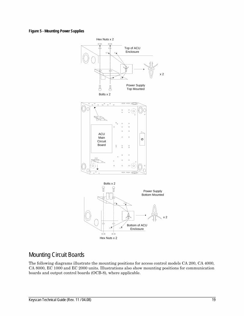
Figure 5 - Mounting Power Supplies
Power SupplyTop Mounted
Hex Nuts x 2
Bolts x 2
Top of ACUEnclosure
x 2
ACUMain
CircuitBoard
Hex Nuts x 2
Power SupplyBottom Mounted
Bolts x 2
Bottom of ACUEnclosure
x 2
Mounting Circuit Boards The following diagrams illustrate the mounting positions for access control models CA 200, CA 4000, CA 8000, EC 1000 and EC 2000 units. Illustrations also show mounting positions for communication boards and output control boards (OCB-8), where applicable.

Keyscan Technical Guide (Rev. 11 / 04.08) 20
Important Do not mount access control units close to high voltage equipment.
Figure 6 - CA 200 with Circuit Board Mounting Positions
Front View - Cover not shown
Tamper Switch
Power Supply
NETCOMor
CB-485or
CB-485Mor
MC9600or
CPB-10
1 x CA 230 circuit board 1 x OCB-81 x DPS-12 power supply1 x metal enclosure
Parts
CA230Main
CircuitBoard
OCB-8
OptionalOCB-8
Locations
OptionalOCB-8
LocationsGround Lug
Wireless NETCOM or NETCOM
Wireless NETCOM antenna
Power Supply
Figure 7 - CA 4000 with Circuit Board Mounting Positions
Front View - Cover not shown
Tamper Switch
Power Supply
NETCOMor
CB-485or
CB-485Mor
MC9600or
CPB-10
1 x CA 4300 circuit board 1 x OCB-81 x DPS-12 power supply1 x metal enclosure
Parts
CA4300Main
CircuitBoard
OCB-8
OptionalOCB-8
Locations
OptionalOCB-8
LocationsGround Lug
Wireless NETCOM or NETCOM
Wireless NETCOM antenna
Power Supply

Keyscan Technical Guide (Rev. 11 / 04.08) 21
Figure 8 - CA 8000 with Circuit Board Mounting Positions
Front View - Cover not shown
Tamper Switch
Power Supply
NETCOMor
CB-485or
CB-485Mor
MC9600or
CPB-10
1 x CA 8300 circuit board 2 x OCB-81 x DPS-12 power supply1 x metal enclosure
Parts
CA8300Main
CircuitBoard
OCB-8
OptionalOCB-8
LocationsGround Lug
Wireless NETCOM or NETCOM
Wireless NETCOM antenna
Power Supply
OCB-8
Figure 9 - EC 1000 with Circuit Board Mounting Positions
Front View - Cover not shown
Tamper Switch
Power Supply
NETCOMor
CB-485or
CB-485Mor
MC9600or
CPB-10
1 x EC 1300 circuit board 1 x OCB-81 x DPS-12 power supply1 x metal enclosure
Parts
EC1300Main
CircuitBoard
OCB-8
OptionalOCB-8
LocationsGround Lug
Wireless NETCOM or NETCOM
Wireless NETCOM antenna
Power Supply
OptionalOCB-8
Locations
Keyscan Technical Guide (Rev. 11 / 04.08) 22
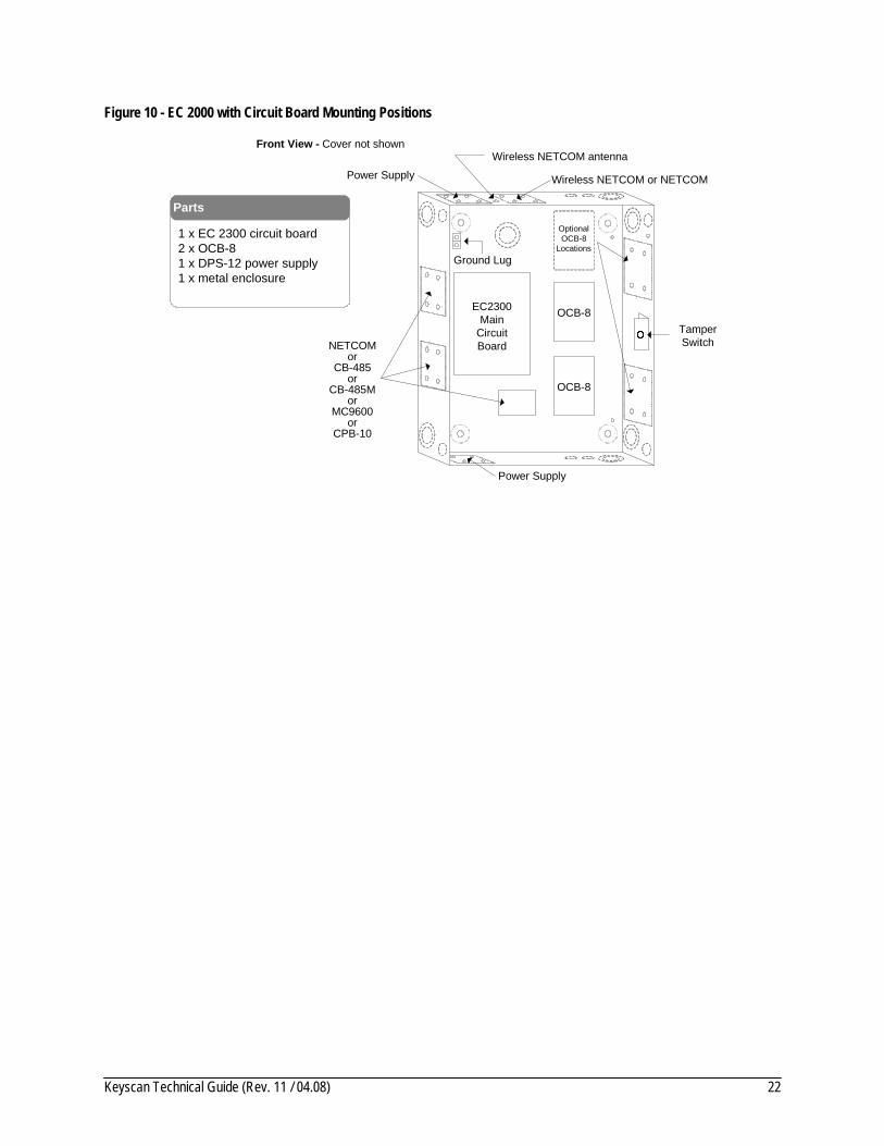
Figure 10 - EC 2000 with Circuit Board Mounting Positions
Front View - Cover not shown
Tamper Switch
Power Supply
NETCOMor
CB-485or
CB-485Mor
MC9600or
CPB-10
1 x EC 2300 circuit board 2 x OCB-81 x DPS-12 power supply1 x metal enclosure
Parts
EC2300Main
CircuitBoard
OCB-8
OptionalOCB-8
LocationsGround Lug
Wireless NETCOM or NETCOM
Wireless NETCOM antenna
Power Supply
OCB-8

Keyscan Technical Guide (Rev. 11 / 04.08) 23
ACU Enclosure Ground Strap Ensure that the ACU Enclosure Ground Strap is connected to the designated studs on both the ACU cover and ACU enclosure. Be sure the cable lug is positioned between two star washers and securely tightened with a nut as illustrated in the diagram below.
Figure 11 - ACU Enclosure Ground Strap Connection
ACU Enclosure Ground Strap
ACU Enclosure Cover ACU Enclosure
Use enclosed star washers and nuts to secure both ends of cable to studs as shown below.
StudStud
StarWashers
Nut
Cable Lug
Stud
Side View of Stud with Cable Lug Connection

Keyscan Technical Guide (Rev. 11 / 04.08) 24
Figure 12 - Securing the Enclosure Cover
Front View of Enclosure with Cover
3/8“ x 4
Cover Locking Screw
Cover Locking Screw
Cover Locking Screw
Cover Locking Screw
Optional locations for cover locking screws
Optional locations for cover locking screws

Keyscan Technical Guide (Rev. 11 / 04.08) 25
Mounting Readers & Door Hardware The following sub-sections review door components and related diagrams. Refer to the lock manufacturer's documentation for more detailed information on mounting door hardware. Some jurisdictions require a qualified locksmith for installation of lock hardware. Consult with local authorities.
• door lock hardware – page 26 • door contacts, exit buttons, auxiliary inputs – page 27 • readers – page 28
The following diagram shows a single conduit to the access control unit. For high voltage readers greater than 150mA, avoid running the communication cables in the same conduit with the door lock cables.
Figure 13 – Typical Door Layout
3/4" conduitto ACU
Junctionbox
Reader
Requestto exit PIR
36" to 48"
Door contact
3 pairs shielded22 AWG
2 pairs22 AWG
1 pair18 AWG
Mag Lock
DoorStrike
1 pair22 AWGPIR requires 3 pairs if
connecting to soundalert.
Keyscan Technical Guide (Rev. 11 / 04.08) 26
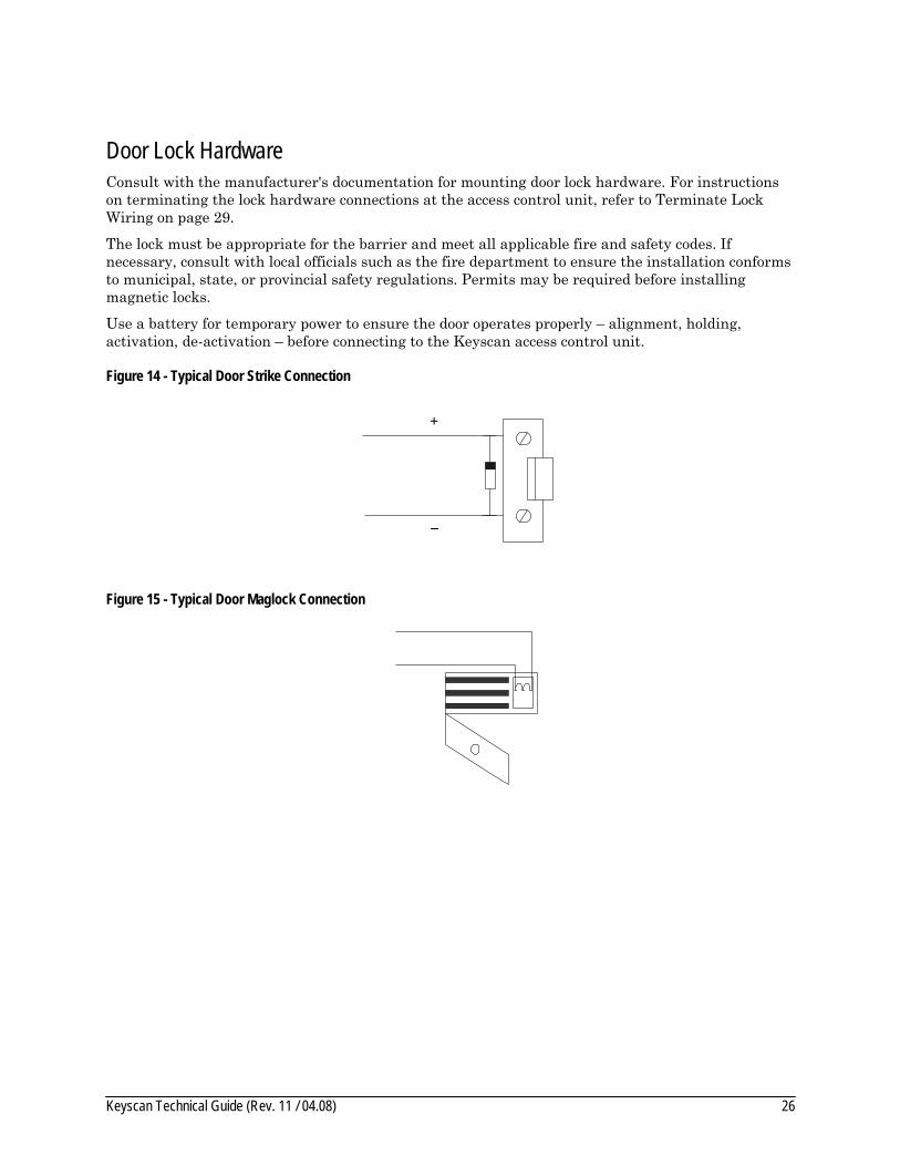
Door Lock Hardware Consult with the manufacturer's documentation for mounting door lock hardware. For instructions on terminating the lock hardware connections at the access control unit, refer to Terminate Lock Wiring on page 29.
The lock must be appropriate for the barrier and meet all applicable fire and safety codes. If necessary, consult with local officials such as the fire department to ensure the installation conforms to municipal, state, or provincial safety regulations. Permits may be required before installing magnetic locks.
Use a battery for temporary power to ensure the door operates properly – alignment, holding, activation, de-activation – before connecting to the Keyscan access control unit.
Figure 14 - Typical Door Strike Connection
+
Figure 15 - Typical Door Maglock Connection

Keyscan Technical Guide (Rev. 11 / 04.08) 27
Door Contacts, Exit Buttons, Auxiliary Inputs The following diagram illustrates the door contacts, exit buttons, PIRs, and auxiliary inputs. See the manufacturer's documentation for mounting instructions. Avoid running cables parallel with AC wiring or across florescent light fixtures. This causes AC induction and transmission interference.
Figure 16 - Door Contacts, Exit Buttons, PIRs, & Auxiliary Inputs
Exit Push Button
1
1
Door Contact
NC COM
Door Sensor
DoorSensor
AuxiliaryInput
LensNO COM
COM
NO
PIRRTE - 1/4 second pulse(Request To Exit)
1
1
Aux Input
COMNC
NO = Normally OpenNC = Normally Closed
Keyscan Technical Guide (Rev. 11 / 04.08) 28
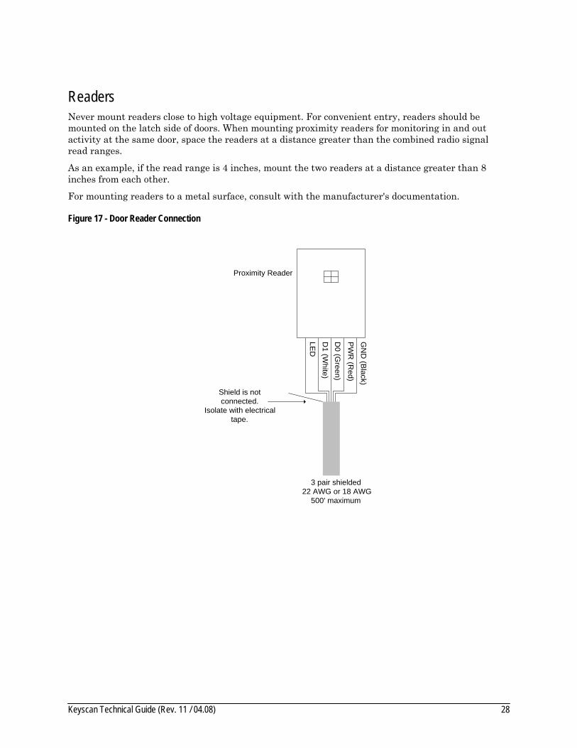
Readers Never mount readers close to high voltage equipment. For convenient entry, readers should be mounted on the latch side of doors. When mounting proximity readers for monitoring in and out activity at the same door, space the readers at a distance greater than the combined radio signal read ranges.
As an example, if the read range is 4 inches, mount the two readers at a distance greater than 8 inches from each other.
For mounting readers to a metal surface, consult with the manufacturer's documentation.
Figure 17 - Door Reader Connection
LED
D1 (W
hite)D
0 (Green)
PW
R (R
ed)
GN
D (B
lack)
Shield is notconnected.
Isolate with electricaltape.
3 pair shielded 22 AWG or 18 AWG
500' maximum
Proximity Reader

Keyscan Technical Guide (Rev. 11 / 04.08) 29
Terminate Wiring at the ACU The following sub-sections review terminating system wiring at the access control units:
• terminate lock wiring – page 29 • terminate input wiring – page 35 • terminate elevator floor wiring – page 40 • terminate floor input wiring – page 43 • terminate reader wiring – page 44 • terminate auxiliary outputs with hardware/alarms – page 46
Terminate Lock Wiring A separate power supply must be used for door strikes and other 12VDC equipment. The power supply should have battery backup for continued operation during a power failure. When adding equipment to an existing system, be sure the power supply can withstand the increased current consumption.
To calculate total current requirements for power supplies, use the following formula which includes a 30% tolerance factor:
• Total Current = (Device A amps + Device B amps + Device C amps, etc.) x 1.30
Example An installation calls for 1 magnetic lock and 3 door strikes requiring 12VDC:
Mag Lock 100mA + Door Strike A 200mA + Door Strike B 200mA + Door Strike C 200mA x 1.30 = 910mA
In this example, a separate 1-amp power supply is sufficient.
Important The total current of the devices must not be greater than the current of the power supply.
Relay Status Jumpers Relay boards have jumpers that may be set to “Normal” or “Reversed”. Each relay has an LED that indicates the relay status:
• Normal – LED on circuit board is not illuminated when door is locked • Reversed – LED on the circuit board is illuminated when door is locked
Diodes are supplied with Keyscan access control panel(s). Diodes must be installed across all D.C. door strikes as shown in Figure 21 on page 33. The anode of the diode is connected to the positive side of the strike at the door. The cathode of the diode is connected to the common return wire.
Diodes must be installed for proper operation.

Keyscan Technical Guide (Rev. 11 / 04.08) 30
Fail Safe/Fail Secure Lock Devices The power supply's positive output must be connected to the common door relay outputs, which are labeled on the relay board.
For ‘fail-safe’ and ‘fail-secure’ door strikes, observe the following relay connections:
• ‘Fail-Safe’ – Connect the positive terminal on the door strike to the 'Normally Closed' position on the board relay. Connect the return wire to the Common on the DC power supply via the ground lug on the ACU enclosure.
• ‘Fail-Secure’ – Connect the positive terminal on the door strike to the 'Normally Open' position on the board relay. Connect the return wire to the Common on the DC power supply via the ground lug on the ACU enclosure.
Figure 18 - Lock State - Fail Safe Device
Maglock
+
-
to 'NormallyClosed' positon
on relay
to commonon DC power supply
ACU board relay
ACU board relay+
-
Door Strike
Lock Stateof
Fail Safe Device
DCSupply
+
-Lock
to 'NormallyClosed' positon
on relay
to+
supply
to commonon DC power supply
to+
supply

Keyscan Technical Guide (Rev. 11 / 04.08) 31
Figure 19 - Lock State - Fail Secure Device
to'Normally Open'positon on relay +
-
Door Strike
to commonon DC
power supply
Lock Stateof
Fail Secure DeviceLockDCSupply
+
-
ACU board relay
to+
supply
Warning Before securing any exit, please ensure all wiring to electrical door hardware conforms to federal, state, provincial, or municipal fire and building codes.
Keyscan Technical Guide (Rev. 11 / 04.08) 32
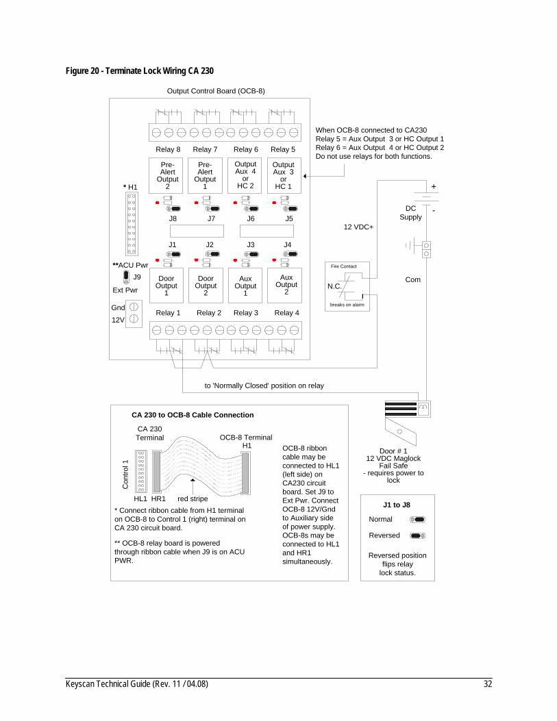
Figure 20 - Terminate Lock Wiring CA 230
to 'Normally Closed' position on relay
Door Output
1
Door Output
2
Aux Output
1
Aux Output
2
J1 J2 J3 J4
J5J6J7J8
Output Control Board (OCB-8)
Gnd
J9
Ext Pwr
12V
**ACU Pwr
* H1
12 VDC+
Com
+
-DCSupply
Relay 1 Relay 2 Relay 3 Relay 4
Relay 5Relay 6Relay 7Relay 8
Normal
Reversed
Reversed positionflips relay
lock status.
J1 to J8* Connect ribbon cable from H1 terminal on OCB-8 to Control 1 (right) terminal on CA 230 circuit board.
** OCB-8 relay board is powered through ribbon cable when J9 is on ACU PWR.
CA 230 to OCB-8 Cable Connection
red stripe
H1
CA 230Terminal OCB-8 Terminal
Con
trol 1
HR1
Door # 112 VDC Maglock
Fail Safe- requires power to
lock
Pre-Alert
Output1
Pre-Alert
Output2
OutputAux 3
orHC 1
OutputAux 4
orHC 2
When OCB-8 connected to CA230Relay 5 = Aux Output 3 or HC Output 1Relay 6 = Aux Output 4 or HC Output 2Do not use relays for both functions.
Fire Contact
breaks on alarm
N.C.
HL1
OCB-8 ribbon cable may be connected to HL1 (left side) on CA230 circuit board. Set J9 to Ext Pwr. Connect OCB-8 12V/Gnd to Auxiliary side of power supply. OCB-8s may be connected to HL1 and HR1 simultaneously.

Keyscan Technical Guide (Rev. 11 / 04.08) 33
Figure 21 - Terminate Lock Wiring CA 4300
to 'Normally Closed' position on relay
Door Output
1
Door Output
2
Door Output
4
DoorOutput
3
Aux Output
1
Aux Output
2
Aux Output
4
AuxOutput
3
J1 J2 J3 J4
J5J6J7J8
Output Control Board (OCB-8)
Gnd
J9
Ext Pwr
12V
**ACU Pwr
* H1
12 VDC+
Com
Fire Contact
breaks on alarm
N.C.
Diode1N4004
Door # 112 VDC Strike
Fail Safe - requires power
to lock
+
-
DCSupply
Relay 1 Relay 2 Relay 3 Relay 4
Relay 5Relay 6Relay 7Relay 8
Normal
Reversed
Reversed positionflips relay
lock status.
J1 to J8
* Connect ribbon cable from H1 terminal on OCB-8 to Control 1 (right) terminal on CA 4300 circuit board.
** OCB-8 relay board is powered through ribbon cable when J9 is on ACU PWR.
CA 4300 to OCB-8 Cable Connection
red stripe
H1
CA 4300Terminal OCB-8 Terminal
Con
trol 1
HR1HL1
OCB-8 ribbon cable may be connected to HL1 (left side) on CA 4300 circuit board. Set J9 to Ext Pwr. Connect OCB-8 12V/Gnd to Auxiliary side of power supply. OCB-8s may be connected to HL1 and HR1 simultaneously.

Keyscan Technical Guide (Rev. 11 / 04.08) 34
Figure 22 - Terminate Lock Wiring CA 8300
to 'Normally Open' position on relay
Door Output
1
Door Output
2
Door Output
4
DoorOutput
3
Door Output
5
Door Output
6
Door Output
8
DoorOutput
7
J1 J2 J3 J4
J5J6J7J8
Output Control Board (OCB-8)
Gnd
J9
Ext Pwr
12V
**ACU Pwr
* H1
12 VDC+
Com
Diode1N4004
Door # 112 VDC Strike
Fail Secure - requires power
to unlock
+
-DC
Supply
Relay 1 Relay 2 Relay 3 Relay 4
Relay 5Relay 6Relay 7Relay 8
Normal
Reversed
Reversed positionflips relay
lock status.
J1 to J8
* Connect ribbon cable from H1 terminal on OCB-8 to Control 1 (right) terminal on CA 8300 circuit board.
** OCB-8 relay board is powered through ribbon cable when J9 is on ACU PWR.
CA 8300 to OCB-8 Cable Connection
red stripe
H1
CA 8300Terminal OCB-8 Terminal
Con
trol 1
HR1HL1
OCB-8 ribbon cable may be connected to HL1 (left side) on CA 8300 circuit board. Set J9 to Ext Pwr. Connect OCB-8 12V/Gnd to Auxiliary side of power supply. OCB-8s may be connected to HL1 and HR1 simultaneously.

Keyscan Technical Guide (Rev. 11 / 04.08) 35
Terminate Input Wiring The following sub-topics review termination of door, exit, and auxiliary alarm input wiring.
Door Monitoring Connections A normally-closed door contact is for monitoring door security. Door inputs are shunted during the door relay unlock time.
Exit Device Connections A normally-open exit device contact unlocks its assigned door for its defined door relay unlock time and overrides the alarm input during its defined door held open time. Examples of exit devices are exit push buttons or motion sensors (PIR) etc.
Keyscan recommends a PIR with a pulse output of ¼ second and suited to its environment.
Security Monitoring Connections A normally-closed device may be connected to an auxiliary alarm input for monitoring stairwell or interior doors, or windows. The auxiliary alarm inputs may be connected to infrared sensors or to an existing alarm system with a normally-closed auxiliary output relay contact.

Keyscan Technical Guide (Rev. 11 / 04.08) 36
Figure 23 - Terminate Input Wiring – Door Contacts CA 230 / CA 4300 / CA 8300
Cut View of CA 8300
Door Contacts Request to Exit 16 Supervised Auxiliary Alarm Inputs
Door ContactNormally Closed
J18 – Jumper 5 & 4 = Off
Door 1
9 10 1112 131415 16
Com
mon R
eturn
1 2 3 4 5 6 7 81 2 3 4 5 6 7 81 2 3 4 5 6 7 8
to Door Contact
1
Door Contact
to Common Return
Normally Closed J18 – Jumper 5 = Off
Jumper 4 = On
1K
Single end of line supervision
Binary
5 4 3 2 1
J18Address | Ext Jmp
A B C D E
to Door Contact
1
Door Contact
to Common Return
Normally Closed J18 Jumper 5 & 4 = On
1K
Double end of line supervision
3K
Non -supervisedNotesDiagram illustrates CA 8300. Connections also apply to CA 230 & CA 4300.- CA 230 – up to 2 door contacts- CA 4300 – up to 4 door contacts- CA 8300 – up to 8 door contacts
J18 – pins 5 & 4 set supervision type (Jumper setting applies to all Door Contact, Request to Exit, and Supervised Auxiliary inputs.)
NC COM
NC COM
NC COM

Keyscan Technical Guide (Rev. 11 / 04.08) 37
Figure 24 - Terminate Input Wiring – RTE Push Button CA 230 / CA 4300 / CA 8300
Cut View of CA 8300
Door Contacts Request to Exit 16 Supervised Auxiliary Alarm Inputs 9 10 1112 131415 16
Com
mon R
eturn1 2 3 4 5 6 7 81 2 3 4 5 6 7 81 2 3 4 5 6 7 8
J18 – Jumper 5 = OffJumper 4 = On
Single end of line supervision
Binary
5 4 3 2 1
J18Address | Ext Jmp
A B C D E
to Request to Exit
to Common Return
J18 Jumper 5 & 4 = On
Double end of line supervision
Non-supervised
NotesDiagram illustrates CA 8300. Connections also apply to CA 230 & CA 4300.- CA 230 – up to 2 Request To Exits- CA 4300 – up to 4 Request To Exits- CA 8300 – up to 8 Request To Exits
RTEPush Button
COM
NO
NO = Normally Open
J18 Jumper 5 & 4 = Off
1K
3K
COM
NO
to Request to Exit
to Common Return
1K
COM
NO
J18 – pins 5 & 4 set supervision type (Jumper setting applies to all Door Contact, Request to Exit, and Supervised Auxiliary inputs.)
Keyscan Technical Guide (Rev. 11 / 04.08) 38
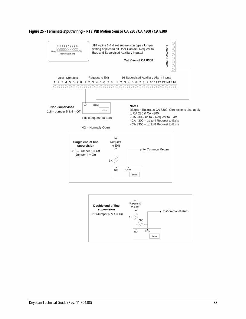
Figure 25 - Terminate Input Wiring – RTE PIR Motion Sensor CA 230 / CA 4300 / CA 8300
Cut View of CA 8300
Door Contacts Request to Exit 16 Supervised Auxiliary Alarm Inputs 9 10 1112 131415 16
Com
mon R
eturn1 2 3 4 5 6 7 81 2 3 4 5 6 7 81 2 3 4 5 6 7 8
toRequestto Exit
to Common ReturnJ18 – Jumper 5 = OffJumper 4 = On
1K
Single end of line supervision
Binary
5 4 3 2 1
J18Address | Ext Jmp
A B C D E
to Common ReturnJ18 Jumper 5 & 4 = On
1K
Double end of line supervision
3K
Non -supervised NotesDiagram illustrates CA 8300. Connections also apply to CA 230 & CA 4300.- CA 230 – up to 2 Request to Exits- CA 4300 – up to 4 Request to Exits- CA 8300 – up to 8 Request to Exits
Lens
NO COM
PIR (Request To Exit)
J18 – Jumper 5 & 4 = Off
Lens
NO COM
Lens
NO COM
toRequestto Exit
NO = Normally Open
J18 – pins 5 & 4 set supervision type (Jumper setting applies to all Door Contact, Request to Exit, and Supervised Auxiliary inputs.)

Keyscan Technical Guide (Rev. 11 / 04.08) 39
Figure 26 - Terminate Input Wiring – Auxiliary/Supervised Inputs CA 230 / CA 4300 / CA 8300
Cut View of CA 8300
Door Contacts Request to Exit 16 Supervised Auxiliary Alarm Inputs
J18 – Jumper 5 & 4 = Off
9 10 11 12 13 1415 16
Com
mon R
eturn
1 2 3 4 5 6 7 81 2 3 4 5 6 7 81 2 3 4 5 6 7 8
to Supervised Auxiliary Alarm Input
1
to Common ReturnJ18 – Jumper 5 = OffJumper 4 = On
1K
Single end of line supervision
Binary
5 4 3 2 1
J18Address | Ext Jmp
A B C D E
1
to Common ReturnJ18 Jumper 5 & 4 = On 1K
Double end of line supervision
3K
Non -supervised
NotesDiagram illustrates CA 8300.Connections also apply to CA 230 & CA 4300.- CA 230 – up to 8 Supervised Auxiliary Alarm Inputs- CA 4300 – up to 16 Supervised Auxiliary Alarm Inputs - CA 8300 – up to 16 Supervised Auxiliary Inputs
NC COM
NC COM
NC COM
NC = Normally Closed
to Supervised Auxiliary Alarm Input
J18 – pins 5 & 4 set supervision type (Jumper setting applies to all Door Contact, Request to Exit, and Supervised Auxiliary inputs.)

Keyscan Technical Guide (Rev. 11 / 04.08) 40
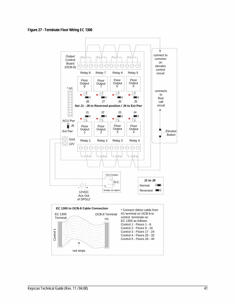
Terminate Elevator Floor Wiring If the elevator control unit (ECU) regulates more than 8 floors, multiple output control boards (OCB-8) are required. See the following table for ribbon cable elevator/floor assignments from the OCB-8 terminal to the ECU terminal.
OCB-8 Jumper Settings • J1 to J8 set to Reversed position • J9 set to EXT PWR
Note Verify all floor hardware conforms to federal, state, provincial or municipal fire codes.
Table 3 – OCB-8 to EC 1300 Ribbon Cable Connections
OCB Terminal ECU Terminal Elevator Floors
1st OCB-8 – H1 Control 1 1 1 – 8
*2nd OCB-8 – H1 Control 2 1 9 – 16
*3rd OCB-8 – H1 Control 3 1 17 – 24
*4th OCB-8 – H1 Control 4 1 25 – 32
*5th OCB-8 – H1 Control 5 1 33 – 40
Table 4 – OCB-8 to EC 2300 Ribbon Cable Connections
OCB Terminal ECU Terminal Elevator Reader Floors
1st OCB-8 – H1 Control 1 1 1 1 – 8
*2nd OCB-8 – H1 Control 2 1 1 9 – 16
3rd OCB-8 – H1 Control 3 2 2 1 – 8
*4th OCB-8 – H1 Control 4 2 2 9 – 16
* Optional OCB-8's must be purchased separately.
Keyscan Technical Guide (Rev. 11 / 04.08) 41
Figure 27 - Terminate Floor Wiring EC 1300
Floor Output
1
Floor Output
2
Floor Output
4
FloorOutput
3
Floor Output
5
Floor Output
6
Floor Output
8
FloorOutput
7
J1 J2 J3 J4
J5J6J7J8
OutputControlBoard
(OCB-8)
Gnd
J9
Ext Pwr
12V
ACU Pwr
* H1
Relay 1 Relay 2 Relay 3 Relay 4
Relay 5Relay 6Relay 7Relay 8
Elevator Button
connectsto
floorcall
circuit
connect tocommon
onelevatorcontrolcircuit
EC 1300 to OCB-8 Cable Connection
red stripe
H1EC 1300Terminal
OCB-8 Terminal
Con
trol 1
* Connect ribbon cable fromH1 terminal on OCB-8 to control terminals onEC 1300 as follows:Control 1 - Floors 1 - 8 Control 2 - Floors 9 - 16Control 3 - Floors 17 - 24Control 4 - Floors 25 - 32 Control 5 - Floors 33 - 40
Set J1 - J8 to Reversed position / J9 to Ext Pwr
Fire Contact
breaks on alarm
N.C.
12VDCAux Out
of DPS12
+-NormalReversed
J1 to J8

Keyscan Technical Guide (Rev. 11 / 04.08) 42
Figure 28 - Terminate Floor Wiring EC 2300
EC 2300 to OCB-8 Cable Connection
red stripe
H1EC 2300Terminal
OCB-8 Terminal
Con
trol 1
* Connect ribbon cable from H1 terminal onOCB-8 to control terminals on EC 2300 as follows:Control 1 - Elevator 1/Reader 1 Floors 1 - 8 Control 2 - Elevator 1/Reader 1 Floors 9 - 16Control 3 - Elevator 2/Reader 2 Floors 1 - 8Control 4 - Elevator 2/Reader 2 Floors 9 - 16
Floor Output
1
Floor Output
2
Floor Output
4
FloorOutput
3
Floor Output
5
Floor Output
6
Floor Output
8
FloorOutput
7
J1 J2 J3 J4
J5J6J7J8
OutputControlBoard
(OCB-8)
Gnd
J9
Ext Pwr
12V
ACU Pwr
* H1
Relay 1 Relay 2 Relay 3 Relay 4
Relay 5Relay 6Relay 7Relay 8
Elevator Button
connectsto
floorcall
circuit
connect tocommon
onelevatorcontrolcircuit
Set J1 - J8 to Reversed position / J9 to Ext Pwr
Fire Contact
breaks on alarm
N.C.
12VDCAux Out
of DPS12
+-NormalReversed
J1 to J8
Keyscan Technical Guide (Rev. 11 / 04.08) 43
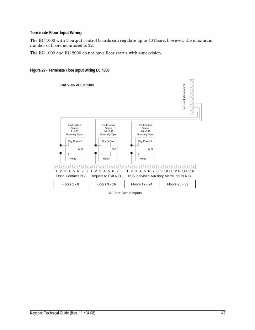
Terminate Floor Input Wiring The EC 1000 with 5 output control boards can regulate up to 40 floors; however, the maximum number of floors monitored is 32.
The EC 1000 and EC 2000 do not have floor status with supervision.
Figure 29 - Terminate Floor Input Wiring EC 1300
Cut View of EC 1300
Call ButtonStatus2 of 32
Normally Open
Com
mon R
eturn
1 2 3 4 5 6 7 81 2 3 4 5 6 7 8 1 2 3 4 5 6 7 8 9 10 1112 131415 16Door Contacts N.C Request to Exit N.O. 16 Supervised Auxiliary Alarm Inputs N.C.
Floors 1 - 8 Floors 9 - 16 Floors 17 - 24 Floors 25 - 32
32 Floor Status Inputs
Dry Contact
Relay
N.O.
Call ButtonStatus
10 of 32Normally Open
Dry Contact
Relay
N.O.
Call ButtonStatus
18 of 32Normally Open
Dry Contact
Relay
N.O.

Keyscan Technical Guide (Rev. 11 / 04.08) 44
Figure 30 - Terminate Floor Input Wiring EC 2300
Cut View of EC 2300
Elevator 1Call Button Status
2 of 16Normally Open
Com
mon R
eturn
1 2 3 4 5 6 7 81 2 3 4 5 6 7 8 1 2 3 4 5 6 7 8 9 10 1112 131415 16Door Contacts N.C Request to Exit N.O. 16 Supervised Auxiliary Alarm Inputs N.C.
Floors 1 - 8 Floors 9 - 16 Floors 1 - 8 Floors 9 - 16
Elevator 1 - 16 Floor Status Inputs
Dry Contact
Relay
N.O.
Elevator 1Call Button Status
10 of 16Normally Open
Dry Contact
Relay
N.O.
Elevator 2Call Button Status
2 of 16Normally Open
Dry Contact
Relay
N.O.
Elevator 2 - 16 Floor Status Inputs
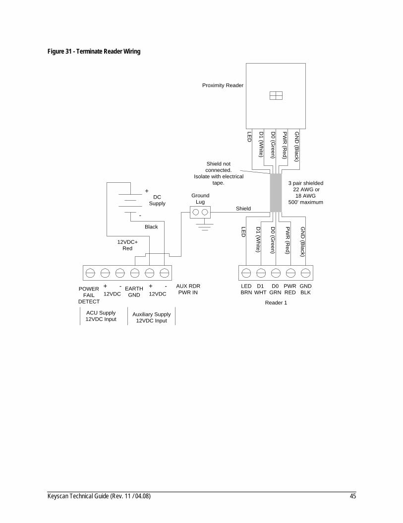
Terminate Reader Wiring at ACU The reader cable should be 3 pair 22AWG shielded or a cable with overall shielding. 18 AWG is acceptable for current demanding readers such as the Indala PX620 or the HID5375. The shielding wire from each pair must be connected to the earth ground lug at the ACU and isolated and taped at the reader. The maximum reader distance is 500 feet (152.4 m) from the controller when transmitting a Wiegand signal protocol. If the distance is greater than 500 feet (152.4 m), install one WIEEX per reader, which extends the distance to 4000 feet (1219.2 m). See Appendix F – Wiegand Extenders WIEEX and CWIEEX on page 133.
Reader Wiring • Red – Positive DC Power. Each reader port is fused at 12VDC at 120 mA. For readers that
draw more current, connect the red wire directly to the power supply. • Black – Ground (GND) • Brown – Light Emitting Diode (LED) on reader • Green – Data output bit 0 • White – Data output bit 1
For specific reader wiring review the appendices listed in the Table of Contents.
Keyscan Technical Guide (Rev. 11 / 04.08) 45
Figure 31 - Terminate Reader Wiring
LED
D1 (W
hite)
D0 (G
reen)
PW
R (R
ed)
GN
D (B
lack)
Shield notconnected.
Isolate with electricaltape. 3 pair shielded
22 AWG or18 AWG
500' maximum
LEDBRN
D1WHT
D0GRN
PWRRED
GNDBLK
Reader 1
AUX RDRPWR IN
EARTHGND 12VDC
+ -12VDC+ -POWER
FAILDETECT
Auxiliary Supply12VDC Input
ACU Supply12VDC Input
DCSupply
+
-
12VDC+Red
Black
Proximity Reader
Shield
GroundLug
LED
D1 (W
hite)
D0 (G
reen)
PW
R (R
ed)
GN
D (B
lack)

Keyscan Technical Guide (Rev. 11 / 04.08) 46
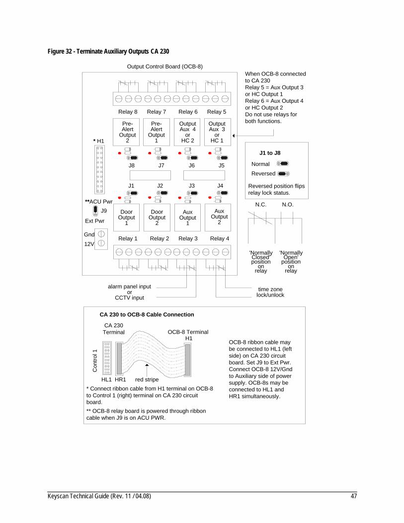
Terminate Auxiliary Outputs with Hardware/Alarms Door and auxiliary inputs can be programmed to trip auxiliary output relays on an alarm event. This excludes pre-alert relays. Auxiliary output relays can be connected to alarm panels, CCTV systems etc.
As an example, a forced entry detected by a door input could be programmed to trip an auxiliary output which initiates a CCTV system to record the intrusion at the door.
Auxiliary output relays may also be used to control hardware with an associated time zone, such as scheduling the locking/unlocking of a door, which does not have a reader, to a defined time zone.
Important Do not assign a time zone to an auxiliary output if the output has previously been assigned to an alarm event. The alarm has priority over the time zone.
Keyscan Technical Guide (Rev. 11 / 04.08) 47
Figure 32 - Terminate Auxiliary Outputs CA 230
'Normally Closed'position
onrelay
'Normally Open'
positionon
relay
N.O.N.C.
alarm panel inputor
CCTV inputtime zone
lock/unlock
Door Output
1
Door Output
2
Aux Output
1
Aux Output
2
OutputAux 3
orHC 1
J1 J2 J3 J4
J5J6J7J8
Output Control Board (OCB-8)
Gnd
J9
Ext Pwr
12V
**ACU Pwr
* H1
Relay 1 Relay 2 Relay 3 Relay 4
Relay 5Relay 6Relay 7Relay 8
OutputAux 4
orHC 2
Pre-Alert
Output1
Pre-Alert
Output2
When OCB-8 connected to CA 230Relay 5 = Aux Output 3 or HC Output 1Relay 6 = Aux Output 4 or HC Output 2Do not use relays for both functions.
Normal
Reversed
Reversed position flips relay lock status.
J1 to J8
* Connect ribbon cable from H1 terminal on OCB-8 to Control 1 (right) terminal on CA 230 circuit board. ** OCB-8 relay board is powered through ribbon cable when J9 is on ACU PWR.
CA 230 to OCB-8 Cable Connection
red stripe
H1
CA 230Terminal OCB-8 Terminal
Con
trol 1
HR1HL1
OCB-8 ribbon cable may be connected to HL1 (left side) on CA 230 circuit board. Set J9 to Ext Pwr. Connect OCB-8 12V/Gnd to Auxiliary side of power supply. OCB-8s may be connected to HL1 and HR1 simultaneously.
Keyscan Technical Guide (Rev. 11 / 04.08) 48
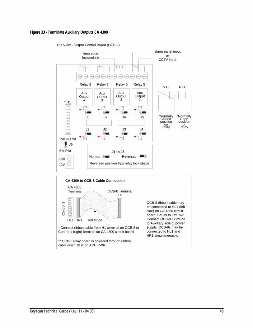
Figure 33 - Terminate Auxiliary Outputs CA 4300
Aux Output
1
Aux Output
2
Aux Output
4
AuxOutput
3
J1 J2 J3 J4
J5J6J7J8
Cut View - Output Control Board (OCB-8)
Gnd
J9
Ext Pwr
12V
**ACU Pwr
* H1
Relay 5Relay 6Relay 7Relay 8
'Normally Closed'position
onrelay
'Normally Open'
positionon
relay
N.O.N.C.
Normal Reversed
Reversed position flips relay lock status.
J1 to J8
time zonelock/unlock
alarm panel inputor
CCTV input
* Connect ribbon cable from H1 terminal on OCB-8 to Control 1 (right) terminal on CA 4300 circuit board.
** OCB-8 relay board is powered through ribbon cable when J9 is on ACU PWR.
CA 4300 to OCB-8 Cable Connection
red stripe
H1
CA 4300Terminal OCB-8 Terminal
Con
trol 1
HR1HL1
OCB-8 ribbon cable may be connected to HL1 (left side) on CA 4300 circuit board. Set J9 to Ext Pwr. Connect OCB-8 12V/Gnd to Auxiliary side of power supply. OCB-8s may be connected to HL1 and HR1 simultaneously.
Keyscan Technical Guide (Rev. 11 / 04.08) 49
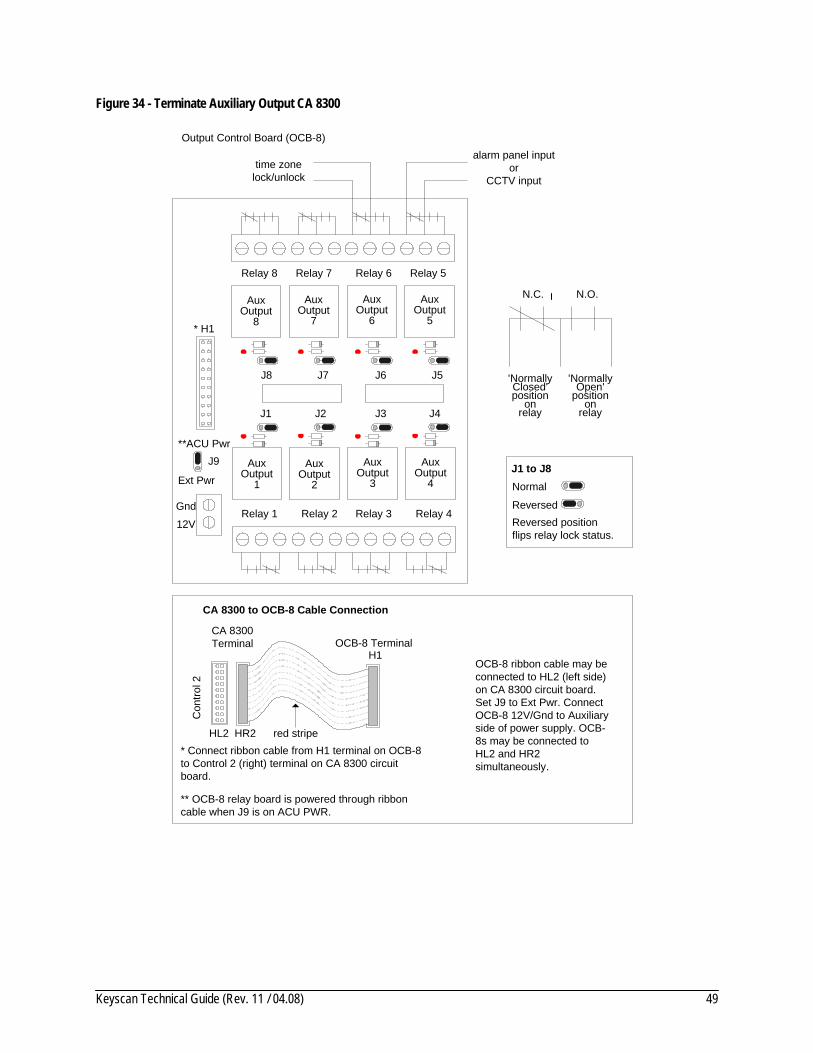
Figure 34 - Terminate Auxiliary Output CA 8300
Aux Output
1
Aux Output
2
Aux Output
4
AuxOutput
3
Aux Output
5
Aux Output
6
Aux Output
8
AuxOutput
7
J1 J2 J3 J4
J5J6J7J8
Output Control Board (OCB-8)
Gnd
J9
Ext Pwr
12V
**ACU Pwr
* H1
Relay 1 Relay 2 Relay 3 Relay 4
Relay 5Relay 6Relay 7Relay 8
'Normally Closed'position
onrelay
'Normally Open'
positionon
relay
N.O.N.C.
Normal
Reversed Reversed positionflips relay lock status.
J1 to J8
time zonelock/unlock
alarm panel inputor
CCTV input
* Connect ribbon cable from H1 terminal on OCB-8 to Control 2 (right) terminal on CA 8300 circuit board.
** OCB-8 relay board is powered through ribbon cable when J9 is on ACU PWR.
CA 8300 to OCB-8 Cable Connection
red stripe
H1
CA 8300Terminal OCB-8 Terminal
Con
trol 2
HR2HL2
OCB-8 ribbon cable may be connected to HL2 (left side) on CA 8300 circuit board. Set J9 to Ext Pwr. Connect OCB-8 12V/Gnd to Auxiliary side of power supply. OCB-8s may be connected to HL2 and HR2 simultaneously.
Keyscan Technical Guide (Rev. 11 / 04.08) 50
ACU/ECU Jumper Settings The following sub-sections outline jumper settings on ACU and ECU circuit boards:
• communications, card name storage, reader LEDs, card count, SI inputs jumper J16 – page 50 • software version selection jumper J17 – page 53 • reader technology selection jumper J3 – page 54 • address / external jumper J18 – page 57 • clear ACU memory jumper J1 – page 60
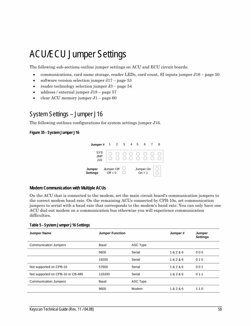
System Settings – Jumper J16 The following outlines configurations for system settings jumper J16.
Figure 35 - System Jumper J16
1 2 3 4 5 6 7 8
SYSJMPJ16
Jumper OffOff = 0
Jumper OnOn = 1
Jumper #
Jumper Settings
Modem Communication with Multiple ACUs On the ACU that is connected to the modem, set the main circuit board's communication jumpers to the correct modem baud rate. On the remaining ACUs connected by CPB-10s, set communication jumpers to serial with a baud rate that corresponds to the modem's baud rate. You can only have one ACU dial-out modem on a communication bus otherwise you will experience communication difficulties.
Table 5 - System Jumper J16 Settings
Jumper Name Jumper Function Jumper # Jumper Settings
Communication Jumpers Baud ASC Type
9600 Serial 1 & 2 & 6 0 0 0
19200 Serial 1 & 2 & 6 0 1 0
Not supported on CPB-10 57600 Serial 1 & 2 & 6 0 0 1
Not supported on CPB-10 or CB-485 115200 Serial 1 & 2 & 6 0 1 1
Communication Jumpers Baud ASC Type
9600 Modem 1 & 2 & 6 1 1 0

Keyscan Technical Guide (Rev. 11 / 04.08) 51
Jumper Name Jumper Function Jumper # Jumper Settings
Not supported with CPB-10 19200 Modem 1 & 2 & 6 1 0 0
For future use 1 & 2 & 6 1 1 1
For future use 1 & 2 & 6 1 0 1
3 n/a
Card Name Storage in ACU Option (Prom version 6.2.X or higher)
System V or VII software - names stored in ACU - 24,000 card capacity
4 1
System V or VII software – names not stored in ACU – 32,000 card capacity (Disaster recovery utility unable to retrieve names from ACU in the event database is lost or corrupted when this option selected)
4 0
Reader LED (condition on door lock status) Red & Green LED type reader (board revs 9.8b or higher)
5 1
Red LED type reader 5 0
Enable/Disable Temporary Card Countdown Enable Temporary Card Countdown (Prom version 6.07 or higher)
7 1
Disable Temporary Card Countdown 7 0
Enable/Disable SI Inputs
Firmware 7.30 to 8.11 & greater Disable IOCB1616 8 1
Enable IOCB1616 8 0
Firmware 6.07 to 7.04 (does not support IOCB1616)
Enable AL32/64 8 1
Disable AL32/64 8 0
Firmware 7.11 to 7.25 (custom) Enable IOCB1616 8 1
Enable AL32/64 8 0
Firmware 7.05 to 7.10 (custom) Enable IOCB1616 8 1
Disable IOCB1616 8 0
Keyscan Technical Guide (Rev. 11 / 04.08) 52
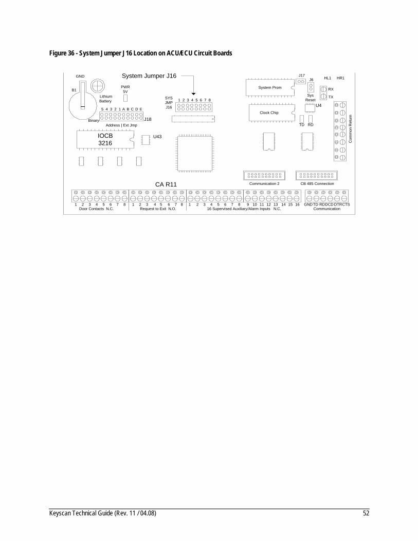
Figure 36 - System Jumper J16 Location on ACU/ECU Circuit Boards
PWR 5V
LithiumBattery
B1
SYS JMPJ16
1
CB 485 Connection
J17J6
SysReset
TX
RX
HR1HL1
Com
mon
Ret
urn
1 Door Contacts N.C.
2 3 4 1 2 3 4 Request to Exit N.O.
1 2 3 4 5 6 16 Supervised Auxiliary/Alarm Inputs N.C.
7 8 9 10 11 12 13 14 15 16 Communication
GNDTD RDDCD DTRCTS5 6 7 85 6 7 8
TD RD
System Prom
Clock Chip
Communication 2
IOCB3216
2 3 4 5 6 7 8
GND
CA R11
U43
U4
System Jumper J16
Binary
5 4 3 2 1
J18Address | Ext Jmp
A B C D E

Keyscan Technical Guide (Rev. 11 / 04.08) 53
Software Selection – Jumper J17 Jumper J17 selects the Keyscan software. If jumper J17 is altered, you must clear memory to reset ACU board settings. In the event of a software version upgrade, jumper J17 does not have to be changed. Refer to the table below for jumper settings.
Important When installing the ACU/ECU circuit board or changing jumper J17, you must clear the ACU memory by momentarily shorting Clear Memory jumper J1.
Figure 37 - Software Jumper J17
J17
Jumper OffOff = 0
Jumper OnOn = 1
JumperSettings
Table 6 - Software Jumper J17
Software Version PROM Version ACU/ECU Version Jumper Settings
System V or System VII 7.4.0 or higher Rev. 11.x 0
System V or System VII 7.x.x to 7.3.9 Rev. 10.x 0
System V or System VII 6.5.0 Rev.10.x 1
System V or System VII 6.11 to 6.22 Rev. 9.x 0
Current ACU hardware no longer supports System 3 or 3 Plus software. Please contact Keyscan technical support.
Figure 38 - Software Jumper J17 Location on CA & EC boards
PWR 5V
LithiumBattery
B1
SYS JMPJ16
1
CB 485 Connection
J17
J6
SysReset
TX
RX
HR1HL1
Com
mon
Ret
urn
1 Door Contacts N.C.
2 3 4 1 2 3 4 Request to Exit N.O.
1 2 3 4 5 6 16 Supervised Auxiliary/Alarm Inputs N.C.
7 8 9 10 11 12 13 14 15 16 Communication
GNDTD RDDCD DTRCTS5 6 7 85 6 7 8
TD RD
System Prom
Clock Chip
Communication 2
IOCB3216
2 3 4 5 6 7 8
GND
CA R11
U43
U4
Software Jumper J17
Binary
5 4 3 2 1
J18Address | Ext Jmp
A B C D E

Keyscan Technical Guide (Rev. 11 / 04.08) 54
Reader Formats – Jumper J3 Jumper J3 sets the ACU or ECU main circuit board to the corresponding reader format. The table below lists the reader format, the corresponding jumper setting and the security level of the card/reader format.
26-bit cards and tags are not secure. Duplicate card numbers exist in this format so a facility is vulnerable to unauthorized access. KEYSCAN assumes no responsibility for liability should any 26-bit card format be enabled in a KEYSCAN system. Further, Keyscan assumes no responsibility for liability for any other format except Keyscan’s proprietary 36-bit format.
KEYSCAN systems are factory defaulted to use KEYSCAN’s proprietary 36-bit Wiegand format cards and tags. KEYSCAN’s 36-bit proprietary Wiegand format ensures no duplicate cards or tags exist offering a high level of security.
Waiver of Liability Installing dealers should have an authorized end-user sign a waiver of liability before enabling 26-bit cards. Keyscan has enclosed a Waiver of Liability on page 57.
Figure 39 - Reader Type Jumper J3
Jumper OffOff = 0
Jumper OnOn = 1
5 4 3 2 1
J3Reader Type
Jumper Settings
JumperPins
6
Note Reader formats apply to PROM version 2.23 or greater. Keyscan 36 bit format is a proprietary format.
Table 7 - Reader Type Jumper J3
Ref # Reader Format Security Level
Jumper Settings Pins 6 - 1
Batch Code Notes
0 Keyscan 36 bit only High 0 0 0 0 0 0 Batch code and facility code are the same for cards or tags
Formats Not Recommended
1 Standard 26 bit & Keyscan 36 bit Low 0 0 0 0 0 1 "
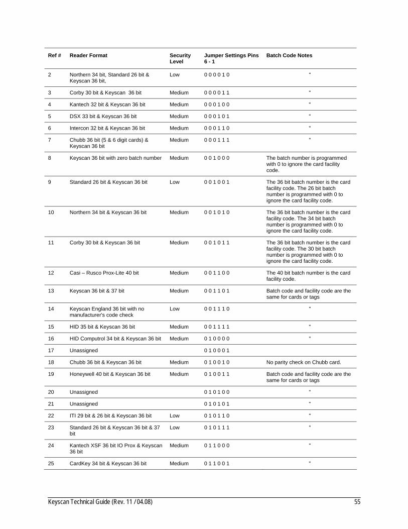
Keyscan Technical Guide (Rev. 11 / 04.08) 55
Ref # Reader Format Security Level
Jumper Settings Pins 6 - 1
Batch Code Notes
2 Northern 34 bit, Standard 26 bit & Keyscan 36 bit,
Low 0 0 0 0 1 0 "
3 Corby 30 bit & Keyscan 36 bit Medium 0 0 0 0 1 1 "
4 Kantech 32 bit & Keyscan 36 bit Medium 0 0 0 1 0 0 "
5 DSX 33 bit & Keyscan 36 bit Medium 0 0 0 1 0 1 "
6 Intercon 32 bit & Keyscan 36 bit Medium 0 0 0 1 1 0 "
7 Chubb 36 bit (5 & 6 digit cards) & Keyscan 36 bit
Medium 0 0 0 1 1 1 "
8 Keyscan 36 bit with zero batch number Medium 0 0 1 0 0 0 The batch number is programmed with 0 to ignore the card facility code.
9 Standard 26 bit & Keyscan 36 bit Low 0 0 1 0 0 1 The 36 bit batch number is the card facility code. The 26 bit batch number is programmed with 0 to ignore the card facility code.
10 Northern 34 bit & Keyscan 36 bit Medium 0 0 1 0 1 0 The 36 bit batch number is the card facility code. The 34 bit batch number is programmed with 0 to ignore the card facility code.
11 Corby 30 bit & Keyscan 36 bit Medium 0 0 1 0 1 1 The 36 bit batch number is the card facility code. The 30 bit batch number is programmed with 0 to ignore the card facility code.
12 Casi – Rusco Prox-Lite 40 bit Medium 0 0 1 1 0 0 The 40 bit batch number is the card facility code.
13 Keyscan 36 bit & 37 bit Medium 0 0 1 1 0 1 Batch code and facility code are the same for cards or tags
14 Keyscan England 36 bit with no manufacturer's code check
Low 0 0 1 1 1 0 "
15 HID 35 bit & Keyscan 36 bit Medium 0 0 1 1 1 1 "
16 HID Computrol 34 bit & Keyscan 36 bit Medium 0 1 0 0 0 0 "
17 Unassigned 0 1 0 0 0 1
18 Chubb 36 bit & Keyscan 36 bit Medium 0 1 0 0 1 0 No parity check on Chubb card.
19 Honeywell 40 bit & Keyscan 36 bit Medium 0 1 0 0 1 1 Batch code and facility code are the same for cards or tags
20 Unassigned 0 1 0 1 0 0 "
21 Unassigned 0 1 0 1 0 1 "
22 ITI 29 bit & 26 bit & Keyscan 36 bit Low 0 1 0 1 1 0 "
23 Standard 26 bit & Keyscan 36 bit & 37 bit
Low 0 1 0 1 1 1 "
24 Kantech XSF 36 bit IO Prox & Keyscan 36 bit
Medium 0 1 1 0 0 0 "
25 CardKey 34 bit & Keyscan 36 bit Medium 0 1 1 0 0 1 "

Keyscan Technical Guide (Rev. 11 / 04.08) 56
Ref # Reader Format Security Level
Jumper Settings Pins 6 - 1
Batch Code Notes
26 Keyscan 36 bit & 26 bit with no parity checking format (Example Keri part # SM-2000X, 05454-030)
Low 0 1 1 0 1 0 "
27 Modern 30 bit & 26 bit & Keyscan 36 bit
Low 0 1 1 0 1 1 "
28 Intercon 32 bit & Keyscan 36 bit & Standard 26 bit
0 1 1 1 0 0 Both batch and card require programming
29 Indala 27 bit (format 10251) & Keyscan 36 bit
0 1 1 1 0 1
30 Cards between 26 bit & 40 bit read as 26 bit card location with parity check
Very Low 0 1 1 1 1 0 Batch or facility codes are read as a 26 bit batch location
31 Diagnostic - evaluates cards between 26 bit & 40 bit for Keyscan engineers only.
Display Only
0 1 1 1 1 1 Cards do not unlock door relays. Evaluation mode only.
For other custom Wiegand protocol firmware or development, contact Keyscan technical support.
ACU/ECU Circuit Board LED Wiegand Bit Counters ACU & ECU circuit boards have Wiegand bit counter LEDs – L1 and L2 – for determining card binary bits. To verify the binary bits, present the card or tag at the reader. You must be able to observe the ACU/ECU circuit board when you present the card or tag at the reader. Count the number of times each LED blinks.
• L1 counts the 1st binary digit • L0 counts the 2nd binary digit
Example If L1 blinks 2 times and L0 blinks 6 times, the card has 26 binary bits (26 bit Wiegand card).
Figure 40 - Reader Format Jumper J3 and Wiegand Bit Counter LEDs
(For all CA & EC control panels)
Aux RdrPwr In
12VDC
PowerFail
DetectACU
PowerIN
+
-
EARTHGND
12VDC+
-
Reader TypeJ3
L1 L0
Reader Prom
J7ReaderReset
F11
Wiegand Bit Counter LEDsL1 & L0
Reader Format Jumpers J3
123456

Keyscan Technical Guide (Rev. 11 / 04.08) 57
Liability Warning – 26 Bit Wiegand Card Format KEYSCAN systems are factory defaulted for KEYSCAN's proprietary 36-bit Wiegand format cards.
KEYSCAN systems can be modified to recognize a wide range of additional access card formats. Some of these formats are proprietary to other system manufacturers. Some other formats, notably 26-bit Wiegand, are “open”. This means that card manufacturers will supply any card number sequence requested. The “open” 26-bit format means duplicate cards exist.
Installing dealers and end-users should be aware of the risk. Because the 26-bit format is unregulated, duplicated card numbers can be easily obtained and could be used to gain unauthorized access to a facility.
KEYSCAN strongly recommends that installing dealers apprise the end user customer of the risks posed by 26-bit cards and have the end user customer acknowledge they understand the risk by signing the “Waiver of Liability”.
Waiver of Liability Keyscan system end user (End User Name - ) acknowledges that he/she has been advised that the KEYSCAN system installed by (Dealer Name - ) in the end-user premises has been modified from the factory original settings to accept Wiegand 26 bit format cards.
End user acknowledges that he/she is aware that duplicate cards may exist in this format and that a duplicate card could be used to gain illegal access to his/her facility.
(Dealer Name - ) SHALL NOT BE RESPONSIBLE FOR ANY CONSEQUENTIAL, CONTINGENT, SPECIAL OR INCIDENTAL DAMAGES whatsoever, except as specifically set forth in the LIMITED WARRANTY, caused by illegal use of duplicate 26 bit access cards.
DEALER NAME: END USER NAME:
PER: PER:
SIGNED: SIGNED:
DATED: DATED:

Keyscan Technical Guide (Rev. 11 / 04.08) 58
This page is intentionally blank.
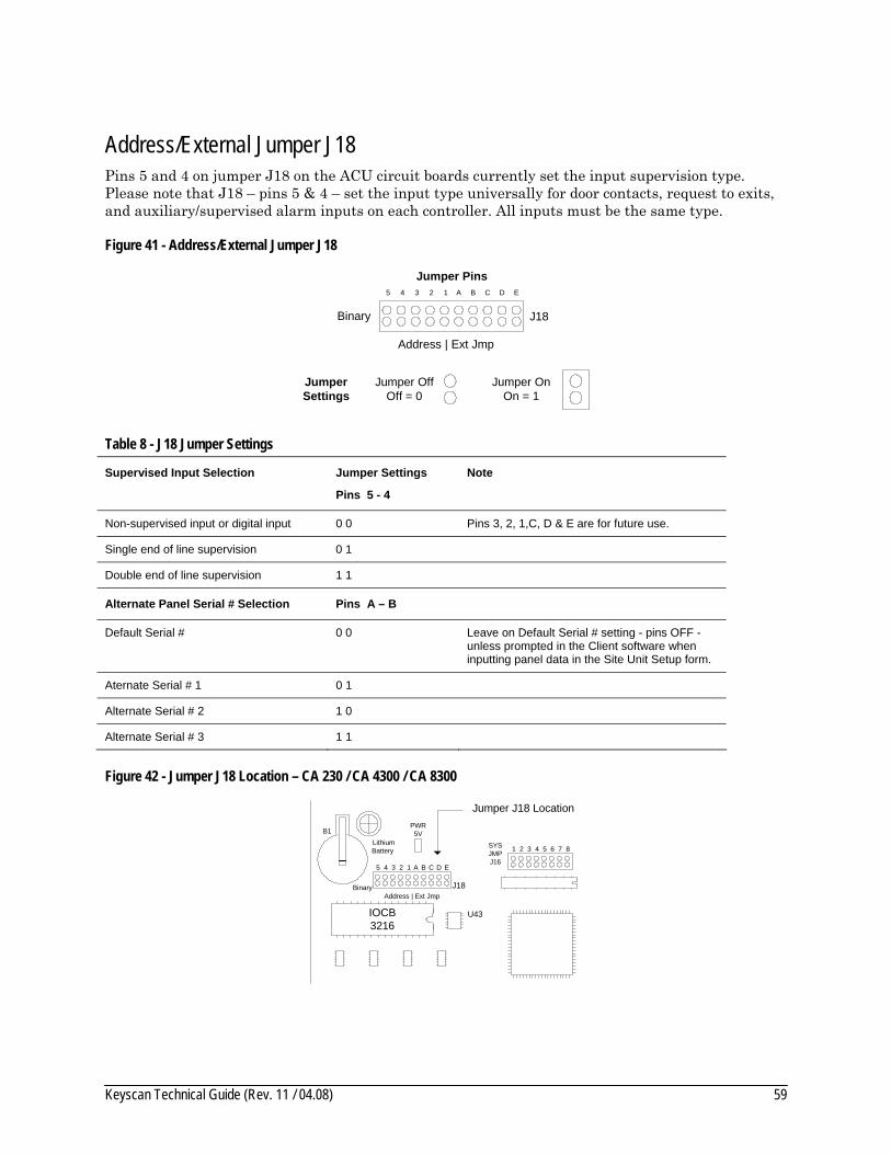
Keyscan Technical Guide (Rev. 11 / 04.08) 59
Address/External Jumper J18 Pins 5 and 4 on jumper J18 on the ACU circuit boards currently set the input supervision type. Please note that J18 – pins 5 & 4 – set the input type universally for door contacts, request to exits, and auxiliary/supervised alarm inputs on each controller. All inputs must be the same type.
Figure 41 - Address/External Jumper J18
Binary
5 4 3 2 1
J18
Address | Ext Jmp
A B C D E
Jumper OffOff = 0
Jumper OnOn = 1
Jumper Settings
Jumper Pins
Table 8 - J18 Jumper Settings
Supervised Input Selection Jumper Settings
Pins 5 - 4
Note
Non-supervised input or digital input 0 0 Pins 3, 2, 1,C, D & E are for future use.
Single end of line supervision 0 1
Double end of line supervision 1 1
Alternate Panel Serial # Selection Pins A – B
Default Serial # 0 0 Leave on Default Serial # setting - pins OFF - unless prompted in the Client software when inputting panel data in the Site Unit Setup form.
Aternate Serial # 1 0 1
Alternate Serial # 2 1 0
Alternate Serial # 3 1 1
Figure 42 - Jumper J18 Location – CA 230 / CA 4300 / CA 8300
PWR 5V
LithiumBattery
B1
SYS JMPJ16
1
IOCB3216
2 3 4 5 6 7 8
U43
Binary
5 4 3 2 1
J18Address | Ext Jmp
A B C D E
Jumper J18 Location
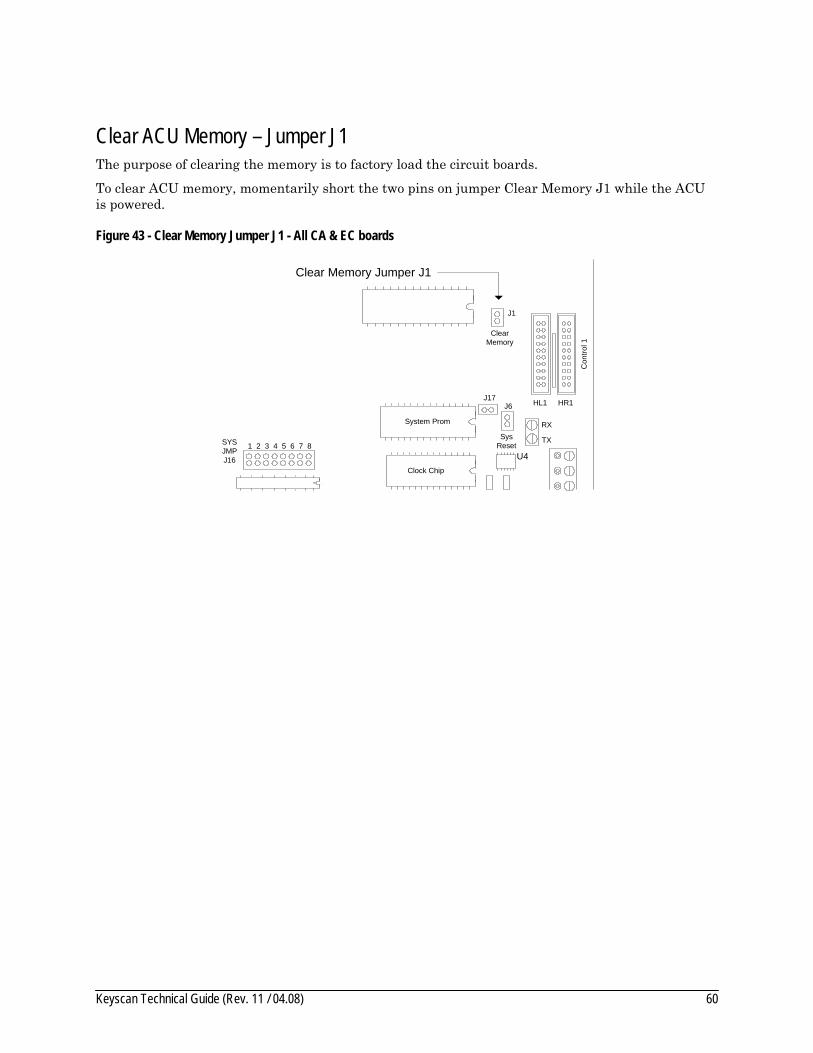
Keyscan Technical Guide (Rev. 11 / 04.08) 60
Clear ACU Memory – Jumper J1 The purpose of clearing the memory is to factory load the circuit boards.
To clear ACU memory, momentarily short the two pins on jumper Clear Memory J1 while the ACU is powered.
Figure 43 - Clear Memory Jumper J1 - All CA & EC boards
SYS JMPJ16
1
J17
ClearMemory
J1
J6
SysReset
TX
RX
Con
trol 1
HR1HL1
System Prom
Clock Chip
2 3 4 5 6 7 8
U4
Clear Memory Jumper J1

Keyscan Technical Guide (Rev. 11 / 04.08) 61
Communication – Single & Multiple ACUs This section outlines ACU to PC communication and ACU to ACU communication. Keyscan supports the following connectivity modes:
• Serial • USB (USB 1.1 & USB 2.0 supported) • Network (TCP/IP) • Wireless Network (TCP/IP) • Modem
Communication is divided into 2 parts:
• Single ACU Communication • Multiple ACU Communication
Each section reviews the supported communication modes, applicable communication devices and connection diagrams.
Important Do not mix CPB-10 boards with CB-485 boards on the same communication loop.
Refer to page 50 for setting communication ACU baud rates. Be sure the correct baud rate of the PC's communication port is set in the Client software. Verify the PC communication port is active and is dedicated for access control communication.
Modem Communication Modem communication requires independent analog phone lines and modems at both the PC and the remote ACU location.
We recommend using either the CB-485M or MC9600 and the MC33H modem because they are manufactured by Keyscan specifically for our access control systems. Setup strings for the modems are defaulted in the Keyscan software. Other 3rd party modems may be used; however, you may encounter problems.
Do not connect a CB-485M, MC9600 or MC33H modem to a digital phone line. If digital phone lines are in use, contact your phone service provider for converter equipment.
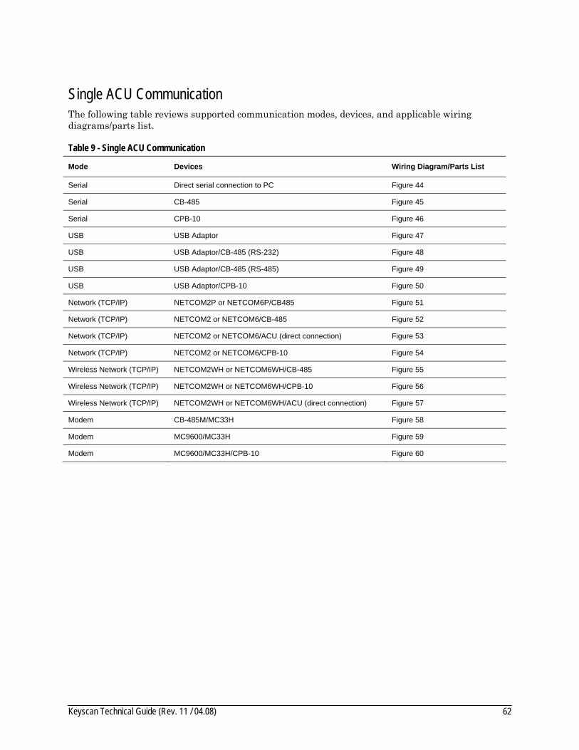
Keyscan Technical Guide (Rev. 11 / 04.08) 62
Single ACU Communication The following table reviews supported communication modes, devices, and applicable wiring diagrams/parts list.
Table 9 - Single ACU Communication
Mode Devices Wiring Diagram/Parts List
Serial Direct serial connection to PC Figure 44
Serial CB-485 Figure 45
Serial CPB-10 Figure 46
USB USB Adaptor Figure 47
USB USB Adaptor/CB-485 (RS-232) Figure 48
USB USB Adaptor/CB-485 (RS-485) Figure 49
USB USB Adaptor/CPB-10 Figure 50
Network (TCP/IP) NETCOM2P or NETCOM6P/CB485 Figure 51
Network (TCP/IP) NETCOM2 or NETCOM6/CB-485 Figure 52
Network (TCP/IP) NETCOM2 or NETCOM6/ACU (direct connection) Figure 53
Network (TCP/IP) NETCOM2 or NETCOM6/CPB-10 Figure 54
Wireless Network (TCP/IP) NETCOM2WH or NETCOM6WH/CB-485 Figure 55
Wireless Network (TCP/IP) NETCOM2WH or NETCOM6WH/CPB-10 Figure 56
Wireless Network (TCP/IP) NETCOM2WH or NETCOM6WH/ACU (direct connection) Figure 57
Modem CB-485M/MC33H Figure 58
Modem MC9600/MC33H Figure 59
Modem MC9600/MC33H/CPB-10 Figure 60
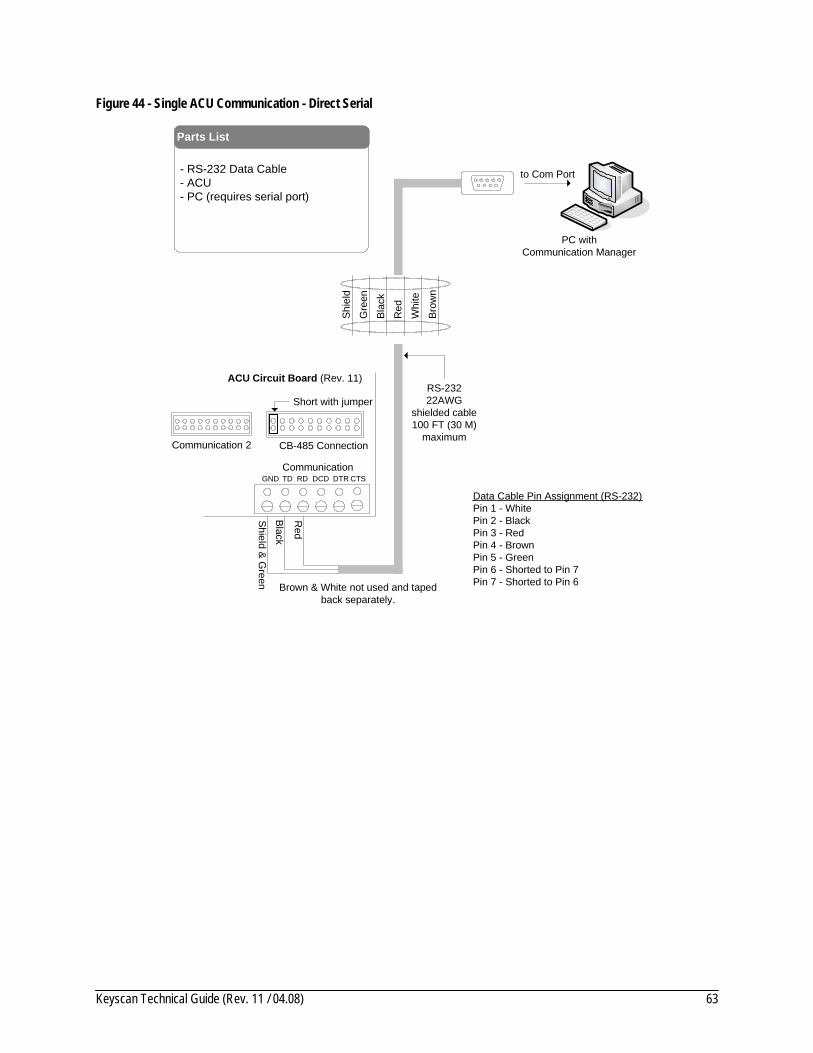
Keyscan Technical Guide (Rev. 11 / 04.08) 63
Figure 44 - Single ACU Communication - Direct Serial
to Com Port
GNDCommunication
ACU Circuit Board (Rev. 11)
Shield & G
reen
Black
Brown & White not used and taped back separately.
CB-485 Connection
Short with jumper
Brow
n
Shie
ld
Gre
en
Blac
k
Red
Whi
te
PC withCommunication Manager
- RS-232 Data Cable- ACU- PC (requires serial port)
Parts List
RS-23222AWG
shielded cable100 FT (30 M)
maximum
TD RD DCD DTR CTS
Red
Data Cable Pin Assignment (RS-232)Pin 1 - WhitePin 2 - BlackPin 3 - RedPin 4 - BrownPin 5 - GreenPin 6 - Shorted to Pin 7Pin 7 - Shorted to Pin 6
Communication 2
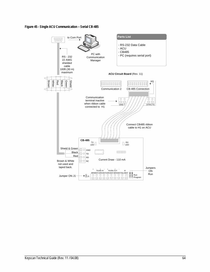
Keyscan Technical Guide (Rev. 11 / 04.08) 64
Figure 45 - Single ACU Communication – Serial CB-485
to Com Port
Brown
Shield
Green
Black
Red
White
PC withCommunication
Manager
- RS-232 Data Cable- ACU- CB485- PC (requires serial port)
Parts List
GND
Brown & White not used and taped back.
Shield & Green
Red
CB-485
J1
CB-485 Connection
H1
Connect CB485 ribbon cable to H1 on ACU
CTSGND T DTR
Communication terminal inactive
when ribbon cable connected to H1
Black
ACU Circuit Board (Rev. 11)
RXLED
TXLED
TD
RD
NC
BRNWHTGRNWHT BRNWHTGRNWHT BLUWHTRS485 IN RS485 OUT M
+ - + - + - + -
Jumper ON J1
RS - 23222 AWG shielded
cable 100ft (30 m) maximum
Current Draw - 110 mA
JumpersONRunRun
Program
Communication 2
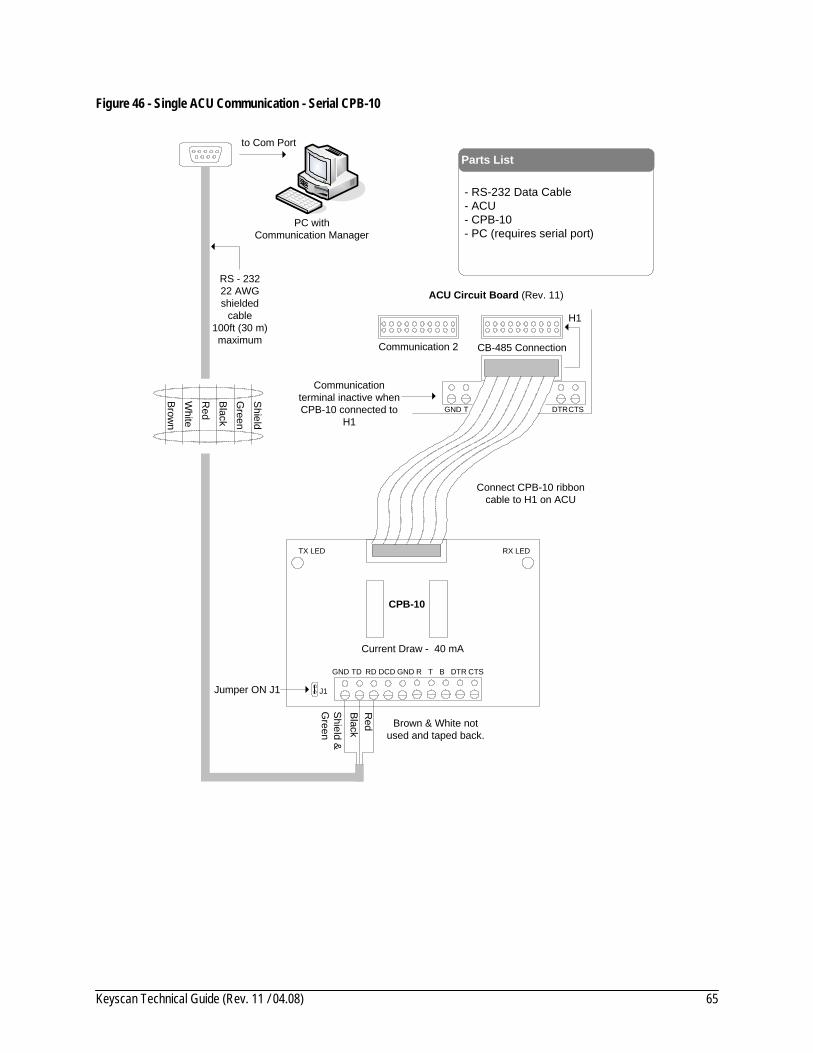
Keyscan Technical Guide (Rev. 11 / 04.08) 65
Figure 46 - Single ACU Communication - Serial CPB-10
to Com Port
RS - 23222 AWG shielded
cable 100ft (30 m) maximum
Brow
n
Shield
Green
Black
Red
White
PC withCommunication Manager
- RS-232 Data Cable- ACU- CPB-10- PC (requires serial port)
Parts List
GND
Brown & White not used and taped back.
Shield &
Green
Red
CPB-10
J1
CB-485 Connection
H1
Connect CPB-10 ribbon cable to H1 on ACU
CTSGND T DTR
Communication terminal inactive when CPB-10 connected to
H1
Black
ACU Circuit Board (Rev. 11)
RX LEDTX LED
TD RD DCD GND R T B DTR CTS
Jumper ON J1
Current Draw - 40 mA
Communication 2
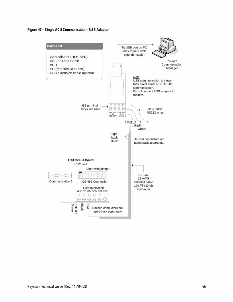
Keyscan Technical Guide (Rev. 11 / 04.08) 66
Figure 47 – Single ACU Communication - USB Adaptor
PC withCommunication
Manager
- USB Adaptor (USB-SER) - RS-232 Data Cable- ACU- PC (requires USB port)- USB extension cable optional
Parts List
BRNWHTGRN WHT+ TX - + RX -
485 OUT 485 IN
To USB port on PC(may require USB extender cable)
485 terminal block not used use 3 loose
RS232 wires
tape back shield
NoteUSB communication is slower than direct serial or NETCOM communication.Do not connect USB adaptor to modem.
GNDCommunication
ACU Circuit Board(Rev. 11)
Shield &
Green
Black
CB-485 Connection
Short with jumper
RS-23222 AWG
shielded cable100 FT (30 M)
maximumTD RD DCD DTR CTS
Red
Green
BlackRed
Unused conductors are taped back separately.
Unused conductors are taped back separately.
Communication 2

Keyscan Technical Guide (Rev. 11 / 04.08) 67
Figure 48 - Single ACU Communication - USB Adaptor/CB-485 (RS232)
RS - 23222 AWG
shielded cable100 FT (30 M)
maximum
PC withCommunication
Manager
- USB Adaptor (USB-SER) - RS-232 Data Cable- CB485- ACU- PC (requires USB port)- USB extension cable optional
Parts List
Green
Black
use 3 loose RS232 wires
tape back shield
GNDShield & Green
Red
CB-485
J1
CB-485 Connection
H1
Connect CB-485 ribbon cable to H1 on ACU
CTSGND T DTR
Communication terminal inactive
when CB-485 connected to H1
Black
ACU Circuit Board(Rev. 11)
RXLED
TXLED
TD
RD
NC
BRN WHTGRNWHT BRN WHTGRNWHT BLUWHTRS485 IN RS485 OUT M
+ - + - + - + -
Jumper ON J1
To USB port on PC(may require USB extension cable)
Red
Unused conductors are taped back separately.
Unused conductors are taped back separately.
Current Draw - 110 mA
BRNWHTGRN WHT+ TX - + RX -
485 OUT 485 IN
NoteUSB communication is slower than direct serial or NETCOM communication.Do not connect USB adaptor to modem.
JumpersONRunRun
Program
Communication 2
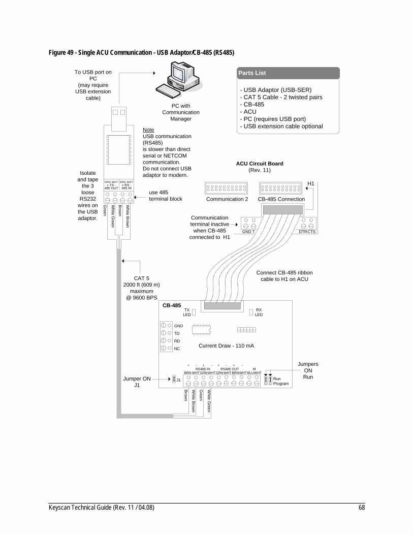
Keyscan Technical Guide (Rev. 11 / 04.08) 68
Figure 49 - Single ACU Communication - USB Adaptor/CB-485 (RS485)
CAT 52000 ft (609 m)
maximum@ 9600 BPS
PC withCommunication
Manager
- USB Adaptor (USB-SER) - CAT 5 Cable - 2 twisted pairs- CB-485- ACU- PC (requires USB port)- USB extension cable optional
Parts List
BRNWHTGRN WHT+ TX - + RX -
485 OUT 485 IN
To USB port on PC
(may require USB extension
cable)
use 485 terminal block
Isolate and tape
the 3 loose
RS232 wires on the USB adaptor.
GND
CB-485
J1
CB-485 Connection
H1
Connect CB-485 ribbon cable to H1 on ACU
CTSGND T DTR
Communication terminal inactive
when CB-485 connected to H1
ACU Circuit Board(Rev. 11)
RXLED
TXLED
TD
RD
NC
BRN WHTGRNWHT BRNWHTGRNWHT BLUWHTRS485 IN RS485 OUT M
+ - + - + - + -
Jumper ON J1
Green
White G
reen
Brown
White Brow
n
Green
White G
reen
Brown
White Brow
n
Current Draw - 110 mA
NoteUSB communication (RS485)is slower than direct serial or NETCOM communication.Do not connect USB adaptor to modem.
JumpersONRunRun
Program
Communication 2
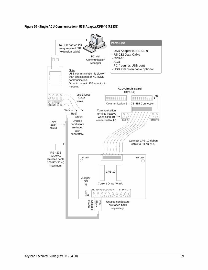
Keyscan Technical Guide (Rev. 11 / 04.08) 69
Figure 50 - Single ACU Communication - USB Adaptor/CPB-10 (RS232)
RS - 23222 AWG
shielded cable100 FT (30 m)
maximum
PC withCommunication
Manager
- USB Adaptor (USB-SER) - RS-232 Data Cable- CPB-10- ACU- PC (requires USB port)- USB extension cable optional
Parts List
BRNWHTGRN WHT+ TX - + RX -
485 OUT 485 IN
To USB port on PC(may require USB extension cable)
tape back shield
CB-485 Connection
H1
Connect CPB-10 ribbon cable to H1 on ACU
CTSGND T DTR
Communication terminal inactive when CPB-10
connected to H1
ACU Circuit Board(Rev. 11)
GND
Unused conductors are taped back
separately.
Shield &G
reen
Red
CPB-10
J1
Black
RX LEDTX LED
TD RD DCD GND R T B DTR CTS
Jumper ONJ1
Green
Black
use 3 loose RS232 wires
Red
Current Draw 40 mA
NoteUSB communication is slower than direct serial or NETCOM communication.Do not connect USB adaptor to modem.
Unused conductors are taped
back separately.
Communication 2

Keyscan Technical Guide (Rev. 11 / 04.08) 70
Figure 51 - Single ACU Communication - NETCOM2P or NETCOM6P/CB-485
- PC - 10/100 Base-T Cable- ACU- CB-485- NETCOM2P or NETCOM6P
Parts List
GND
CB-485
J1
CB-485 Connection
H1
Connect CB-485 ribbon cable to H1 on ACU
CTSGND T DTR
Communication terminal inactive
when CB-485 connected to
H1
ACU Circuit Board(Rev. 11)
RXLED
TXLED
TD
RD
NC
BRN WHT GRNWHT BRN WHTGRNWHT BLU WHTRS485 IN RS485 OUT M
+ - + - + - + -
Jumper ON J1
RJ45
Terminal
JackJ1
U2
NETC
OM
P
to network
to networkHost PC with
Communication Manager
10 or 100 Base-T
Current Draw 250 mA
Communication 2
JumpersONRunRun
Program
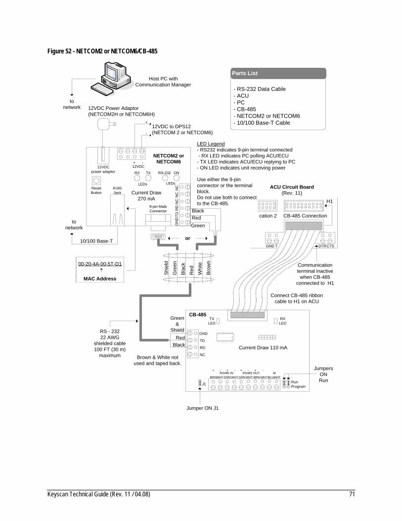
Keyscan Technical Guide (Rev. 11 / 04.08) 71
Figure 52 - NETCOM2 or NETCOM6/CB-485
Host PC withCommunication Manager
- RS-232 Data Cable- ACU- PC- CB-485 - NETCOM2 or NETCOM6- 10/100 Base-T Cable
Parts List
RS - 23222 AWG
shielded cable100 FT (30 m)
maximum
10/100 Base-T
12VDC Power Adaptor(NETCOM2H or NETCOM6H)
tonetwork
12VDCpower adaptor
12VDC + -
ResetButton
RJ45Jack
9-pin MaleConnector
RS-232RX TX ON
00-20-4A-00-5T-D1
MAC Address
12VDC to DPS12(NETCOM 2 or NETCOM6)
LEDsLEDs
GN
DTD
RD
NC
NC
NC
GreenRedBlack
or
NETCOM2 orNETCOM6
Use either the 9-pin connector or the terminal block. Do not use both to connect to the CB-485.
tonetwork
LED Legend- RS232 indicates 9-pin terminal connected - RX LED indicates PC polling ACU/ECU- TX LED indicates ACU/ECU replying to PC- ON LED indicates unit receiving power
Brown & White not used and taped back.
CB-485 Connection
H1
Connect CB-485 ribbon cable to H1 on ACU
CTSGND T DTR
Communication terminal inactive
when CB-485 connected to H1
ACU Circuit Board(Rev. 11)
Brow
n
Shie
ld
Gre
en
Blac
k
Red
Whi
te
+
-
Current Draw270 mA
cation 2
CB-485
J1
RXLED
TXLED
TD
RD
NC
BRNWHTGRNWHT BRN WHTGRNWHT BLUWHTRS485 IN RS485 OUT M
+ - + - + - + -
Jumper ON J1
Current Draw 110 mA
Green&
ShieldRed
Black
GND
JumpersONRunRun
Program

Keyscan Technical Guide (Rev. 11 / 04.08) 72
Figure 53 - Single ACU Communication - NETCOM2 or NETCOM6
Host PC withCommunication Manager
- RS-232 Data Cable- ACU- PC - NETCOM2 or NETCOM6- 10/100 Base-T Cable
Parts List
via shielded 6-wire cable
Brow
n
Shie
ld
Gre
en
Blac
k
Red
Whi
te
10/100 Base-T
12VDC Power Adaptor (NETCOM2H or NETCOM6H)
tonetwork
12VDCpower adaptor
12VDC + -
ResetButton
RJ45Jack
9-pin MaleConnector
RS-232RX TX ON
00-20-4A-00-5T-D1
MAC Address
12VDC to DPS12 (NETCOM2 or NETCOM6)
LEDsLEDs
GN
DTD
RD
NC
NC
NC
GreenRedBlack
or
NETCOM2 orNETCOM6
Use either the 9-pin connector or the terminal block.
Do not use both to connect to the ACU.
tonetwork
LED Legend- RS232 indicates 9-pin terminal connected - RX LED indicates PC polling ACU/ECU- TX LED indicates ACU/ECU replying to PC- ON LED indicates unit receiving power
GNDCommunication
ACU Circuit Board(Rev. 11)
Shield &G
reen
Black
Brown & Whitenot used and
taped back separately.
CB-485 Connection
Short with jumper
RS-23222 AWG
shielded cable100 FT (30 m)
maximumTD RD DCD DTR CTS
Red
Current Draw270 mA
Communication 2
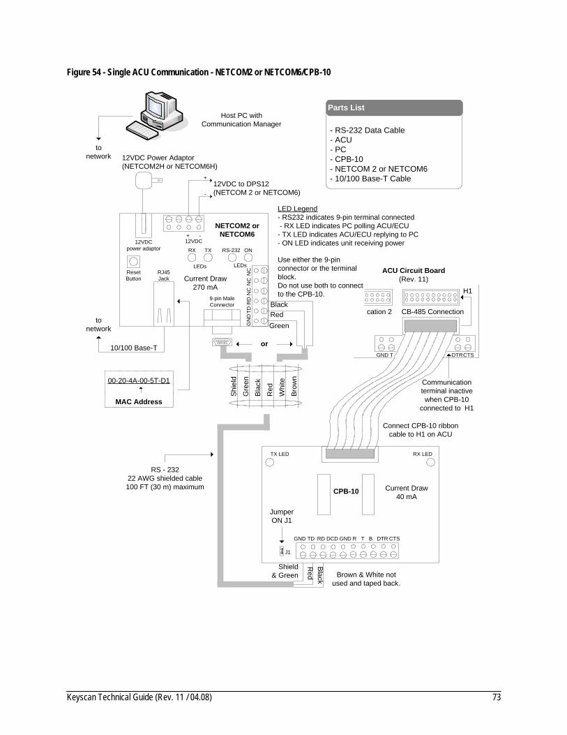
Keyscan Technical Guide (Rev. 11 / 04.08) 73
Figure 54 - Single ACU Communication - NETCOM2 or NETCOM6/CPB-10
Host PC withCommunication Manager
- RS-232 Data Cable- ACU- PC- CPB-10 - NETCOM 2 or NETCOM6- 10/100 Base-T Cable
Parts List
RS - 23222 AWG shielded cable100 FT (30 m) maximum
10/100 Base-T
12VDC Power Adaptor(NETCOM2H or NETCOM6H)
tonetwork
12VDCpower adaptor
12VDC + -
ResetButton
RJ45Jack
9-pin MaleConnector
RS-232RX TX ON
00-20-4A-00-5T-D1
MAC Address
12VDC to DPS12(NETCOM 2 or NETCOM6)
LEDsLEDs
GN
DTD
RD
NC
NC
NC
GreenRedBlack
or
NETCOM2 orNETCOM6
Use either the 9-pin connector or the terminal block. Do not use both to connect to the CPB-10.
tonetwork
LED Legend- RS232 indicates 9-pin terminal connected - RX LED indicates PC polling ACU/ECU- TX LED indicates ACU/ECU replying to PC- ON LED indicates unit receiving power
GND
Brown & White not used and taped back.
Shield& Green
Red
CPB-10
J1
CB-485 Connection
H1
Connect CPB-10 ribbon cable to H1 on ACU
CTSGND T DTR
Communication terminal inactive when CPB-10
connected to H1
Black
ACU Circuit Board(Rev. 11)
RX LEDTX LED
TD RD DCD GND R T B DTR CTS
JumperON J1
Brow
n
Shie
ld
Gre
en
Blac
k
Red
Whi
te
+
-
Current Draw270 mA
Current Draw40 mA
cation 2
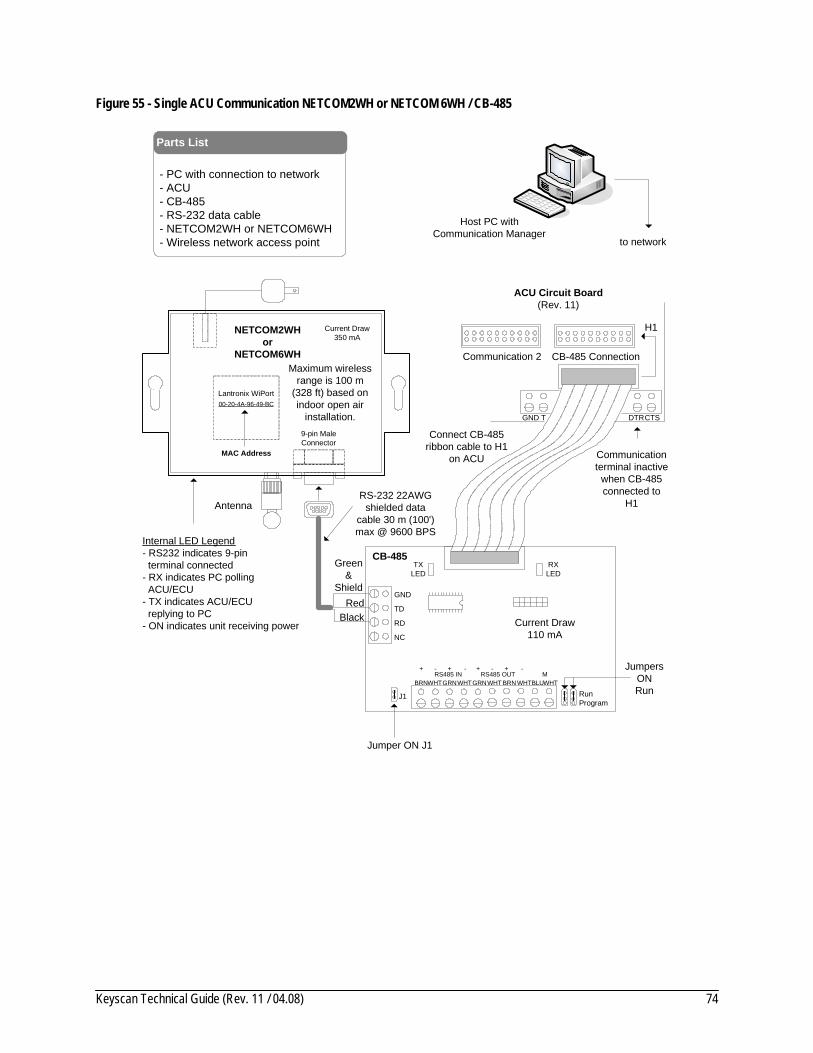
Keyscan Technical Guide (Rev. 11 / 04.08) 74
Figure 55 - Single ACU Communication NETCOM2WH or NETCOM 6WH / CB-485
- PC with connection to network - ACU- CB-485- RS-232 data cable- NETCOM2WH or NETCOM6WH- Wireless network access point
Parts List
GND
CB-485
J1
CB-485 Connection
H1
Connect CB-485 ribbon cable to H1
on ACU
CTSGND T DTR
Communication terminal inactive
when CB-485 connected to
H1
ACU Circuit Board(Rev. 11)
RXLED
TXLED
TD
RD
NC
BRNWHTGRNWHT BRN WHTGRNWHT BLUWHTRS485 IN RS485 OUT M
+ - + - + - + -
Jumper ON J1
to network
Host PC withCommunication Manager
Current Draw 110 mA
9-pin MaleConnector
NETCOM2WH or
NETCOM6WH
Current Draw350 mA
MAC Address
Lantronix WiPort00-20-4A-96-49-BC
Antenna
Internal LED Legend- RS232 indicates 9-pin terminal connected- RX indicates PC polling ACU/ECU- TX indicates ACU/ECU replying to PC- ON indicates unit receiving power
Maximum wireless range is 100 m
(328 ft) based on indoor open air
installation.
RS-232 22AWG shielded data
cable 30 m (100') max @ 9600 BPS
Green&
ShieldRed
Black
Communication 2
JumpersONRunRun
Program
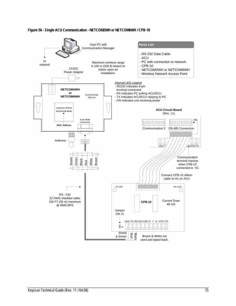
Keyscan Technical Guide (Rev. 11 / 04.08) 75
Figure 56 - Single ACU Communication - NETCOM2WH or NETCOM6WH / CPB-10
Host PC withCommunication Manager
- RS-232 Data Cable- ACU- PC with connection to network- CPB-10 - NETCOM2WH or NETCOM6WH- Wireless Network Access Point
Parts List
RS - 23222 AWG shielded cable100 FT (30 m) maximum
@ 9600 BPS
tonetwork
GND
Brown & White not used and taped back.
Shield& Green
Red
CPB-10
J1
Connect CPB-10 ribbon cable to H1 on ACU
CTSGND T DTR
Communication terminal inactive when CPB-10
connected to H1
Black
RX LEDTX LED
TD RD DCD GND R T B DTR CTS
JumperON J1
Brow
n
Shie
ld
Gre
en
Blac
k
Red
Whi
te
Current Draw40 mA
9-pin MaleConnector
NETCOM2WH or
NETCOM6WH Current Draw350 mA
MAC Address
Lantronix WiPort00-20-4A-96-49-BC
Antenna
Internal LED Legend- RS232 indicates 9-pin terminal connected- RX indicates PC polling ACU/ECU- TX indicates ACU/ECU replying to PC- ON indicates unit receiving power
12VDCPower Adaptor
Maximum wireless range is 100 m (328 ft) based on
indoor open air installation.
CB-485 Connection
H1
ACU Circuit Board(Rev. 11)
Communication 2
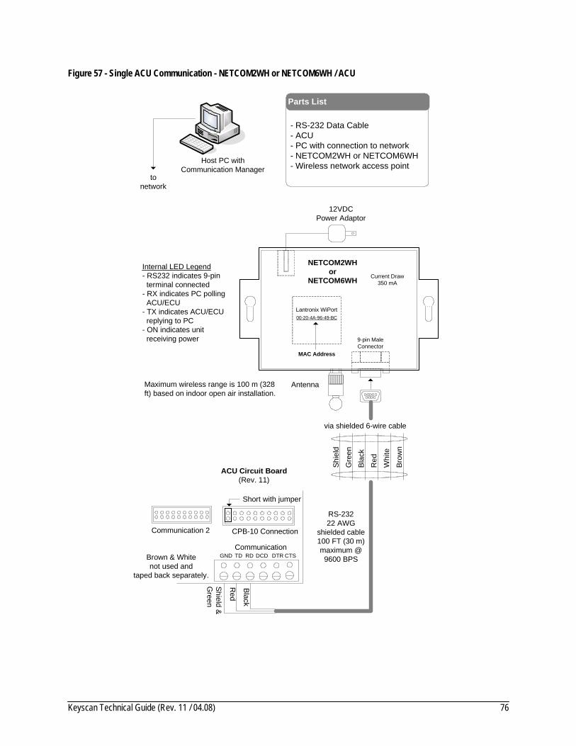
Keyscan Technical Guide (Rev. 11 / 04.08) 76
Figure 57 - Single ACU Communication - NETCOM2WH or NETCOM6WH / ACU
Host PC withCommunication Manager
- RS-232 Data Cable- ACU- PC with connection to network - NETCOM2WH or NETCOM6WH- Wireless network access point
Parts List
via shielded 6-wire cable
Brow
n
Shie
ld
Gre
en
Blac
k
Red
Whi
te
tonetwork
GNDCommunication
Shield &G
reen
Black
Brown & Whitenot used and
taped back separately.
CPB-10 Connection
Short with jumper
RS-23222 AWG
shielded cable100 FT (30 m)maximum @
9600 BPSTD RD DCD DTR CTS
Red
9-pin MaleConnector
NETCOM2WH or
NETCOM6WH Current Draw350 mA
MAC Address
Lantronix WiPort00-20-4A-96-49-BC
Antenna
Internal LED Legend- RS232 indicates 9-pin terminal connected- RX indicates PC polling ACU/ECU- TX indicates ACU/ECU replying to PC- ON indicates unit receiving power
12VDCPower Adaptor
Maximum wireless range is 100 m (328 ft) based on indoor open air installation.
ACU Circuit Board(Rev. 11)
Communication 2
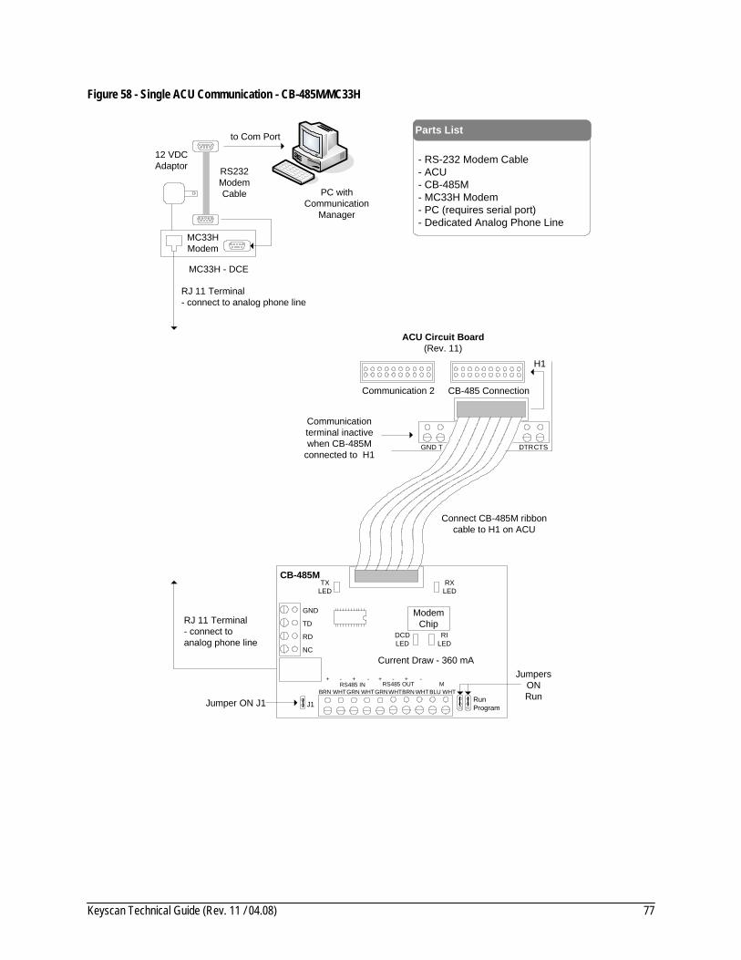
Keyscan Technical Guide (Rev. 11 / 04.08) 77
Figure 58 - Single ACU Communication - CB-485M/MC33H
to Com Port
PC withCommunication
Manager
- RS-232 Modem Cable- ACU- CB-485M- MC33H Modem- PC (requires serial port)- Dedicated Analog Phone Line
Parts List
GND
CB-485M
J1
CB-485 Connection
H1
Connect CB-485M ribbon cable to H1 on ACU
CTSGND T DTR
Communication terminal inactive when CB-485M
connected to H1
ACU Circuit Board(Rev. 11)
RXLED
TXLED
TD
RD
NC
BRN WHTGRN WHT BRN WHTGRNWHT BLU WHTRS485 IN RS485 OUT M
+ - + - + - + -
Jumper ON J1
MC33H Modem
RJ 11 Terminal- connect to analog phone line
12 VDCAdaptor
ModemChipRJ 11 Terminal
- connect to analog phone line
RS232ModemCable
Current Draw - 360 mAJumpers
ONRunRun
Program
DCDLED
RILED
Communication 2
MC33H - DCE
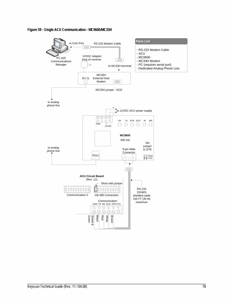
Keyscan Technical Guide (Rev. 11 / 04.08) 78
Figure 59 - Single ACU Communication - MC9600/MC33H
PC withCommunications
Manager
to Com Port RS-232 Modem Cable
to MC33H terminal
to analog phone line
RJ 11MC33H
External Host Modem
MC33H jumper - DCE
- RS-232 Modem Cable- ACU- MC9600- MC33H Modem- PC (requires serial port)- Dedicated Analog Phone Line
Parts List
Set jumper to DTE
to 12VDC ACU power supply
300 mA
GND
MC9600
RX TX MRRIDCD
DCE
-+12VDC
DTR
DTE
9-pin MaleConnector
RJ11
-
+
12VDC Adaptor plug on reverse.
to analog phone line
GNDCommunication
ACU Circuit Board(Rev. 11)
Shield &
Green
Black
CB-485 Connection
Short with jumper
RS-23222AWG
shielded cable100 FT (30 M)
maximumTD RD DCD DTR CTS
Red
White
Brown
Communication 2

Keyscan Technical Guide (Rev. 11 / 04.08) 79
Figure 60 - Single ACU Communication - MC9600/MC33H/CPB-10
PC withCommunications
Manager
to Com Port
RS-232ModemCable
to analog phone line
12VDC Adaptor plug on reverse.
RJ 11MC33H
External Host Modem
to analogphone
line
Set jumper to DTE
MC33H jumper - DCE
- RS-232 Modem Cable- RS-232 Data Cable- ACU- MC9600- MC33H Modem- CPB-10 - PC (requires serial port)- Dedicated Analog Phone Line
Parts List
CB-485 Connection
H1
Connect CPB-10 ribbon cable to H1 on ACU
CTSGND T DTR
Communication terminal inactive when CPB-10
connected to H1
ACU Circuit Board(Rev. 11) to 12VDC ACU power supply
Current Draw 300 mA
GND
MC9600
RX TX MRRIDCD
DCE
-+12VDC
DTR
DTE
9-pin MaleConnector
RJ11
-
+
GND
CPB-10
J1
RX LEDTX LED
TD RD DCD GND R T B DTR CTS
Jumper ONJ1
Shield& Green
Red
Black
White
Brow
n
to 9-pin male
connector
Current Draw40 mA
Communication 2
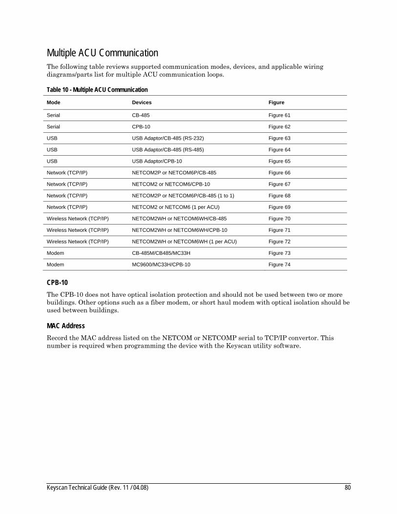
Keyscan Technical Guide (Rev. 11 / 04.08) 80
Multiple ACU Communication The following table reviews supported communication modes, devices, and applicable wiring diagrams/parts list for multiple ACU communication loops.
Table 10 - Multiple ACU Communication
Mode Devices Figure
Serial CB-485 Figure 61
Serial CPB-10 Figure 62
USB USB Adaptor/CB-485 (RS-232) Figure 63
USB USB Adaptor/CB-485 (RS-485) Figure 64
USB USB Adaptor/CPB-10 Figure 65
Network (TCP/IP) NETCOM2P or NETCOM6P/CB-485 Figure 66
Network (TCP/IP) NETCOM2 or NETCOM6/CPB-10 Figure 67
Network (TCP/IP) NETCOM2P or NETCOM6P/CB-485 (1 to 1) Figure 68
Network (TCP/IP) NETCOM2 or NETCOM6 (1 per ACU) Figure 69
Wireless Network (TCP/IP) NETCOM2WH or NETCOM6WH/CB-485 Figure 70
Wireless Network (TCP/IP) NETCOM2WH or NETCOM6WH/CPB-10 Figure 71
Wireless Network (TCP/IP) NETCOM2WH or NETCOM6WH (1 per ACU) Figure 72
Modem CB-485M/CB485/MC33H Figure 73
Modem MC9600/MC33H/CPB-10 Figure 74
CPB-10 The CPB-10 does not have optical isolation protection and should not be used between two or more buildings. Other options such as a fiber modem, or short haul modem with optical isolation should be used between buildings.
MAC Address Record the MAC address listed on the NETCOM or NETCOMP serial to TCP/IP convertor. This number is required when programming the device with the Keyscan utility software.
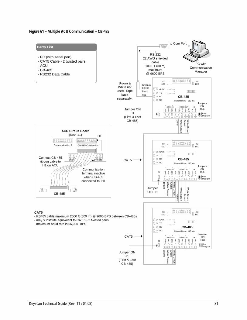
Keyscan Technical Guide (Rev. 11 / 04.08) 81
Figure 61 – Multiple ACU Communication – CB-485
Brown
White Brow
n
White G
reenG
reen
GND
RD
NC
TD
RXLED
TXLED
BRN
WH
T
GR
N
WH
T
BR
N
WH
T
GR
N
WH
T
BLU
WH
T
RS485 IN RS485 OUT M+ - + - + - + -
Current Draw - 110 mA
CB-485
Connect CB-485 ribbon cable to
H1 on ACU
GND
RD
NC
TD
RXLED
TXLED
Current Draw - 110 mA
CB-485
GND
RD
NC
TD
RXLED
TXLED
Current Draw - 110 mA
CB-485
Brown
White Brow
n
White G
reenG
reen
Brown
White B
rown
White G
reenG
reen
Brown
White Brow
n
White G
reenG
reen
- PC (with serial port) - CAT5 Cable - 2 twisted pairs- ACU- CB-485- RS232 Data Cable
Parts Listto Com Port
PC withCommunication
Manager
RS-23222 AWG shielded
cable100 FT (30 m)
maximum@ 9600 BPS
Brown & White not
used. Tape back
separately.
Jumper ONJ1
(First & Last CB-485)
Jumper OFF J1
Jumper ONJ1
(First & Last CB-485)
CAT5
CAT5- RS485 cable maximum 2000 ft (609 m) @ 9600 BPS between CB-485s- may substitute equivalent to CAT 5 - 2 twisted pairs- maximum baud rate is 56,000 BPS
CAT5
Green &Shield
RedBlack
RXLED
TXLED
CB-485
CB-485 Connection
H1
CTSGND T DTR
Communication terminal inactive
when CB-485 connected to H1
ACU Circuit Board(Rev. 11)
J1
J1
J1
BRN
WH
T
GR
N
WH
T
BR
N
WH
T
GR
N
WH
T
BLU
WH
T
RS485 IN RS485 OUT M+ - + - + - + -
BRN
WH
T
GR
N
WH
T
BR
N
WH
T
GR
N
WH
T
BLU
WH
T
RS485 IN RS485 OUT M+ - + - + - + -
JumpersONRun
RunProgram
JumpersONRun
RunProgram
JumpersONRun
RunProgram
Communication 2

Keyscan Technical Guide (Rev. 11 / 04.08) 82
Figure 62 – Multiple ACU Communication – CPB-10
Connect CPB10 ribbon cable to H1 on ACU
- PC (with serial port) - 22 AWG 4 conductors shielded cable- ACU- CPB-10- RS232 Data Cable
Parts List to Com Port
PC withCommunication
Manager
RS-23222 AWG shielded
cable100 FT (30 m)
maximum@ 9600 BPS
Brown & White not
used. Tape back
separately.
Jumper ONJ1
(First & Last CPB10)
Jumper OFF J1
Jumper ONJ1
(First & Last CPB10)
Green &
Shield
Red
Black
RX LEDTX LED
CPB-10
CB-485 Connection
H1
CTSGND T DTR
Communication terminal inactive when CPB-10 connected to
H1
ACU Circuit Board(Rev. 11)
RXLED
TXLED
GND TD RD DCD T BGND R DTR CTS
Current Draw40 mA
J1TO PC
RXLED
TXLED
GND TD RD DCD T BGND R DTR CTS
Current Draw40 mA
CPB-10
J1
RXLED
TXLED
GND TD RD DCD T BGND R DTR CTS
Current Draw40 mA
J1
GN
DR T B
Shield
GN
DR T B
GN
D R T B
GN
DR T B
Shield
Tape back shield
EIA/TIA 562 Signal
CPB-10- supports parallel and star communication (diagram shows CPB-10 in parallel communication)- maximum distance 1st to last CPB-10 - 4000 ft (1219 m) - maximum distance between CPB-10s - 2000 ft (609 m)- see MISCOMM2 for inter-building communication on a CPB-10 communication loop
LegendGND = GroundR = RxT = TxB = Busy Line
CPB-10
CPB-10
Communication 2
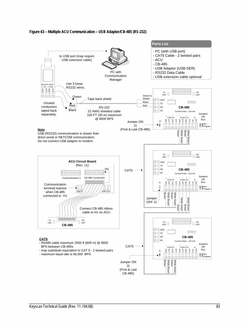
Keyscan Technical Guide (Rev. 11 / 04.08) 83
Figure 63 – Multiple ACU Communication – USB Adaptor/CB-485 (RS-232)
Brown
White B
rown
White G
reenG
reen
GND
RD
NC
TD
RXLED
TXLED
Current Draw - 110 mA
CB-485
Connect CB-485 ribbon cable to H1 on ACU
GND
RD
NC
TD
RXLED
TXLED
Current Draw - 110 mA
CB-485
GND
RD
NC
TD
RXLED
TXLED
Current Draw - 110 mA
CB-485
Brown
White Brow
n
White G
reenG
reen
Brown
White Brow
n
White G
reenG
reen
Brown
White Brow
n
White G
reenG
reen
- PC (with USB port) - CAT5 Cable - 2 twisted pairs- ACU- CB-485- USB Adaptor (USB-SER)- RS232 Data Cable- USB extension cable optional
Parts List
to USB port (may require USB extension cable)
PC withCommunication
Manager
RS-23222 AWG shielded cable100 FT (30 m) maximum
@ 9600 BPS
Unused conductors taped back separately.
Jumper ONJ1
(First & Last CB-485)
Jumper OFF J1
Jumper ONJ1
(First & Last CB-485)
CAT5
CAT5
Green &Shield
RedBlack
RXLED
TXLED
CB-485
CB-485 Connection
H1
CTSGND T DTR
Communication terminal inactive
when CB-485 connected to H1
ACU Circuit Board(Rev. 11)
J1
J1
J1
BR
N
WH
T
GR
N
WH
T
+ TX - + RX -485 OUT 485 IN
Green
Black
Use 3 loose RS232 wires.
Red
Tape back shield.
NoteUSB (RS232) communication is slower than direct serial or NETCOM communication.Do not connect USB adaptor to modem.
BRN
WH
T
GR
N
WH
T
BR
N
WH
T
GR
N
WH
T
BLU
WH
T
RS485 IN RS485 OUT M+ - + - + - + -
BR
N
WH
T
GR
N
WH
T
BR
N
WH
T
GR
N
WH
T
BLU
WH
T
RS485 IN RS485 OUT M+ - + - + - + -
BRN
WH
T
GR
N
WH
T
BR
N
WH
T
GR
N
WH
T
BLU
WH
T
RS485 IN RS485 OUT M+ - + - + - + -
JumpersONRun
RunProgram
JumpersONRun
RunProgram
JumpersONRun
RunProgram
CAT5- RS485 cable maximum 2000 ft (609 m) @ 9600 BPS between CB-485s- may substitute equivalent to CAT 5 - 2 twisted pairs- maximum baud rate is 56,000 BPS
Communication 2

Keyscan Technical Guide (Rev. 11 / 04.08) 84
Figure 64 - Multiple ACU Communication - USB Adaptor/CB-485 (RS-485)
Brown
White Brow
n
White G
reenG
reen
GND
RD
NC
TD
RXLED
TXLED
Current Draw - 110 mA
CB-485
Connect CB-485 ribbon cable to H1 on ACU
GND
RD
NC
TD
RXLED
TXLED
Current Draw - 110 mA
CB-485
GND
RD
NC
TD
RXLED
TXLED
Current Draw - 110 mA
CB-485
Brow
nW
hite Brown
White G
reenG
reen
Brown
White B
rown
White G
reenG
reen
Brow
nW
hite Brow
n
White G
reenG
reen
- PC (with USB port) - CAT5 Cable - 2 twisted pairs- ACU- CB-485- USB Adaptor (USB-SER)- USB extension cable optional
Parts List
to USB port (may require USB extension cable)
PC withCommunication
Manager
CAT52 twisted pairs
2000 ft (609 m) maximum
Isolate and tape the 3
loose RS232 wires on USB
adaptor.
Jumper ONJ1
(First & Last CB-485)
Jumper OFF J1
Jumper ONJ1
(First & Last CB-485)
CAT5
CAT5RXLED
TXLED
CB-485
CB-485 Connection
H1
CTSGND T DTR
Communication terminal inactive when CB-485 connected to
H1
ACU Circuit Board(Rev. 11)
J1
J1
J1
NoteUSB (RS485) communication is slower than direct serial or NETCOM communication.Do not connect USB adaptor to modem.
Brown
White Brow
n
White G
reenG
reen
Brow
nW
hite Brown
White G
reenG
reen
BR
N
WH
T
GR
N
WH
T
BR
N
WH
T
GR
N
WH
T
BLU
WH
T
RS485 IN RS485 OUT M+ - + - + - + -
BR
N
WH
T
GR
N
WH
T
BR
N
WH
T
GR
N
WH
T
BLU
WH
T
RS485 IN RS485 OUT M+ - + - + - + -
BRN
WH
T
GR
N
WH
T
BR
N
WH
T
GR
N
WH
T
BLU
WH
T
RS485 IN RS485 OUT M+ - + - + - + -
BR
N
WH
T
GR
N
WH
T
+ TX - + RX -485 OUT 485 IN
JumpersONRun
RunProgram
JumpersONRun
RunProgram
JumpersONRun
RunProgram
CAT5- RS485 cable maximum 2000 ft (609 m) @ 9600 BPS between CB-485s- may substitute equivalent to CAT 5 - 2 twisted pairs- maximum baud rate is 56,000 BPS
Communication 2
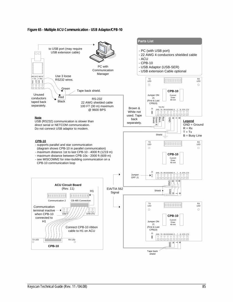
Keyscan Technical Guide (Rev. 11 / 04.08) 85
Figure 65 - Multiple ACU Communication - USB Adaptor/CPB-10
Connect CPB-10 ribbon cable to H1 on ACU
- PC (with USB port) - 22 AWG 4 conductors shielded cable- ACU- CPB-10- USB Adaptor (USB-SER)- USB extension Cable optional
Parts List
Brown & White not
used. Tape back
separately.
Jumper ONJ1
(First & Last CPB10)
Jumper OFF J1
Jumper ONJ1
(First & Last CPB10)
Green &
Shield
Red
Black
RX LEDTX LED
CPB-10
CB-485 Connection
H1
CTSGND T DTR
Communication terminal inactive when CPB-10 connected to
H1
ACU Circuit Board(Rev. 11)
RXLED
TXLED
GND TD RD DCD T BGND R DTR CTS
Current Draw40 mA
J1TO PC
RXLED
TXLED
GND TD RD DCD T BGND R DTR CTS
Current Draw40 mA
CPB-10
J1
RXLED
TXLED
GND TD RD DCD T BGND R DTR CTS
Current Draw40 mA
J1
GN
DR T B
Shield
GN
DR T B
GN
D R T B
GN
DR T B
Shield
Tape back shield
EIA/TIA 562 Signal
CPB-10- supports parallel and star communication (diagram shows CPB-10 in parallel communication)- maximum distance 1st to last CPB-10 - 4000 ft (1219 m) - maximum distance between CPB-10s - 2000 ft (609 m)- see MISCOMM2 for inter-building communication on a CPB-10 communication loop
LegendGND = GroundR = RxT = TxB = Busy Line
CPB-10
CPB-10
to USB port (may require USB extension cable)
PC withCommunication
Manager
RS-23222 AWG shielded cable100 FT (30 m) maximum
@ 9600 BPS
Unused conductors taped back separately.
Green
Black
Use 3 loose RS232 wires.
Red
Tape back shield.
NoteUSB (RS232) communication is slower than direct serial or NETCOM communication.Do not connect USB adaptor to modem.
BR
N
WH
T
GR
N
WH
T
+ TX - + RX -485 OUT 485 IN
Communication 2

Keyscan Technical Guide (Rev. 11 / 04.08) 86
Figure 66 - Multiple ACU Communication - NETCOM2P or NETCOM6P/CB-485
Brown
White Brow
n
White G
reenG
reen
GND
RD
NC
TD
RXLED
TXLED
+ - + -
Current Draw - 250 mACB-485
Connect CB-485 ribbon cable to H1 on ACU
GND
RD
NC
TD
RXLED
TXLED
Current Draw - 110 mA
CB-485
GND
RD
NC
TD
RXLED
TXLED
Current Draw - 110 mA
CB-485
Brown
White B
rown
White G
reenG
reen
Brow
nW
hite Brown
White G
reenG
reen
Brown
White Brow
n
White G
reenG
reen
- PC - CAT5 Cable - 2 twisted pairs- ACU- CB-485- NETCOM2P or NETCOM6P- 10/100 Base-T cable
Parts List
Host PC withCommunication
Manager
Jumper ONJ1
(First & Last CB-485)
Jumper OFF J1
Jumper ONJ1
(First & Last CB-485)
CAT5
RXLED
TXLED
CB-485
CB-485 Connection
H1
CTSGND T DTR
Communication terminal inactive
when CB-485 connected to H1
ACU Circuit Board(Rev. 11)
J1
J1
J1
CAT5
to network
to network
BR
N
WH
T
GR
N
WH
T
BR
N
WH
T
GR
N
WH
T
BLU
WH
T
RS485 IN RS485 OUT M+ - + - + - + -
BRN
WH
T
GR
N
WH
T
BR
N
WH
T
GR
N
WH
T
BLU
WH
T
RS485 IN RS485 OUT M+ - + - + - + -
BR
N
WH
T
GR
N
WH
T
BR
N
WH
T
GR
N
WH
T
BLU
WH
T
RS485 IN RS485 OUT M+ - + - + - + -
NE
TCO
MP
RJ45Terminal
Jack
J1
U2
JumpersONRunRun
Program
JumpersONRun
RunProgram
JumpersONRun
RunProgram
CAT5- RS485 cable maximum 2000 ft (609 m) @ 9600 BPS between CB-485s- may substitute equivalent to CAT 5 - 2 twisted pairs- maximum baud rate is 56,000 BPS
Communication 2
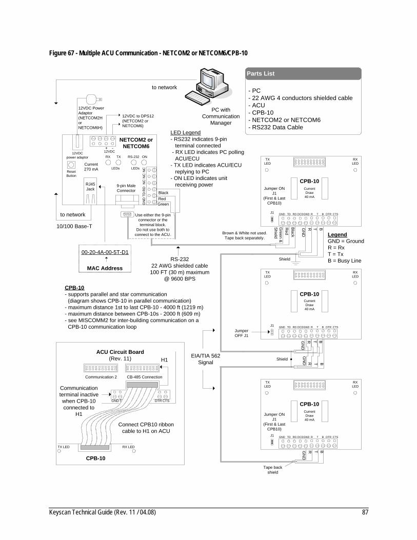
Keyscan Technical Guide (Rev. 11 / 04.08) 87
Figure 67 - Multiple ACU Communication - NETCOM2 or NETCOM6/CPB-10
Connect CPB10 ribbon cable to H1 on ACU
- PC - 22 AWG 4 conductors shielded cable- ACU- CPB-10- NETCOM2 or NETCOM6 - RS232 Data Cable
Parts List
Brown & White not used. Tape back separately.
Jumper ONJ1
(First & Last CPB10)
Jumper OFF J1
Jumper ONJ1
(First & Last CPB10)
Green &
Shield
Red
Black
RX LEDTX LED
CPB-10
CB-485 Connection
H1
CTSGND T DTR
Communication terminal inactive when CPB-10 connected to
H1
ACU Circuit Board(Rev. 11)
RXLED
TXLED
GND TD RD DCD T BGND R DTR CTS
Current Draw40 mA
J1
RXLED
TXLED
GND TD RD DCD T BGND R DTR CTS
Current Draw40 mA
CPB-10
J1
RXLED
TXLED
GND TD RD DCD T BGND R DTR CTS
Current Draw40 mA
J1
GN
DR T B
Shield
GN
DR T B
GN
D R T B
GN
DR T B
Shield
Tape back shield
EIA/TIA 562 Signal
CPB-10- supports parallel and star communication (diagram shows CPB-10 in parallel communication)- maximum distance 1st to last CPB-10 - 4000 ft (1219 m) - maximum distance between CPB-10s - 2000 ft (609 m)- see MISCOMM2 for inter-building communication on a CPB-10 communication loop
LegendGND = GroundR = RxT = TxB = Busy Line
CPB-10
CPB-10
PC withCommunication
Manager
RS-23222 AWG shielded cable100 FT (30 m) maximum
@ 9600 BPS
12VDCpower adaptor
12VDC + -
ResetButton
RJ45Jack
9-pin MaleConnector
RS-232RX TX ON
LEDsLEDs
GN
DTD
RD
NC
NC
NC
NETCOM2 orNETCOM6
GreenRedBlack
Use either the 9-pin connector or the terminal block.
Do not use both to connect to the ACU.
10/100 Base-T
to network
to network
12VDC to DPS12 (NETCOM2 orNETCOM6)
12VDC Power Adaptor(NETCOM2H or NETCOM6H)
LED Legend- RS232 indicates 9-pin terminal connected - RX LED indicates PC polling ACU/ECU- TX LED indicates ACU/ECU replying to PC- ON LED indicates unit receiving power
Current270 mA
00-20-4A-00-5T-D1
MAC Address
Communication 2
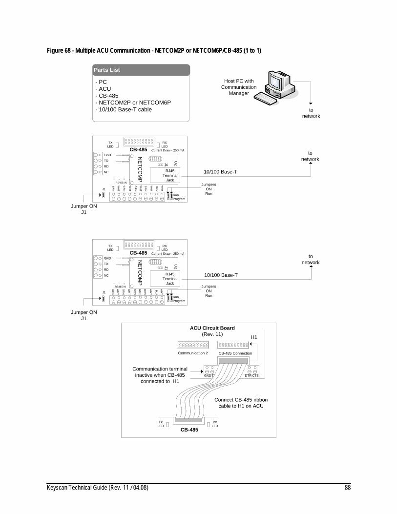
Keyscan Technical Guide (Rev. 11 / 04.08) 88
Figure 68 - Multiple ACU Communication - NETCOM2P or NETCOM6P/CB-485 (1 to 1)
GND
RD
NC
TD
RXLED
TXLED
+ - + -
+ - + -
Current Draw - 250 mACB-485
Connect CB-485 ribbon cable to H1 on ACU
- PC - ACU- CB-485- NETCOM2P or NETCOM6P- 10/100 Base-T cable
Parts List
Host PC withCommunication
Manager
Jumper ONJ1
RXLED
TXLED
CB-485
CB-485 Connection
H1
CTSGND T DTR
Communication terminal inactive when CB-485
connected to H1
ACU Circuit Board(Rev. 11)
J1
NETC
OM
P
RJ45Terminal
Jack
J1
U2
to network
to network
GND
RD
NC
TD
RXLED
TXLED
+ - + -+ - + -
Current Draw - 250 mACB-485
J1
NETC
OM
P
RJ45Terminal
Jack
J1
U2
10/100 Base-T
to network
10/100 Base-T
Jumper ONJ1
BRN
WH
T
GR
N
WH
T
BR
N
WH
T
GR
N
WH
T
BLU
WH
T
RS485 IN
BRN
WH
T
GR
N
WH
T
BR
N
WH
T
GR
N
WH
T
BLU
WH
T
RS485 IN JumpersONRunRun
Program
JumpersONRunRun
Program
Communication 2

Keyscan Technical Guide (Rev. 11 / 04.08) 89
Figure 69 - Multiple ACU Communication - NETCOM2 or NETCOM6 (1 per ACU)
- PC - 10/100 Base-T Cable- ACU- NETCOM2 or NETCOM6 - RS232 Data Cable
Parts List
Brown & White not used. Tape back
separately.
Green &
Shield
Red
Black
Host PC withCommunication
Manager
RS-23222 AWG shielded cable100 FT (30 m) maximum
@ 9600 BPS
12VDCpower adaptor
12VDC + -
ResetButton
RJ45Jack
9-pin MaleConnector
RS-232RX TX ON
LEDsLEDs
GN
DTD
RD
NC
NC
NC
NETCOM2 orNETCOM6
GreenRedBlack
Use either the 9-pin connector or the terminal block.
Do not use both to connect to the ACU.
10/100 Base-T
to network
to network
12VDC to DPS12 (NETCOM2 orNETCOM6)
12VDC Power Adaptor(NETCOM2H or NETCOM6H)
LED Legend- RS232 indicates 9-pin terminal connected - RX LED indicates PC polling ACU/ECU- TX LED indicates ACU/ECU replying to PC- ON LED indicates unit receiving power
Current270 mA
00-20-4A-00-5T-D1
MAC Address
CB-485 Connection
Short with jumper.
ACU Circuit Board(Rev. 11)
Brown & White not used. Tape back
separately.
Green &
Shield
Red
Black
12VDCpower adaptor
12VDC + -
ResetButton
RJ45Jack
9-pin MaleConnector
RS-232RX TX ON
LEDsLEDs
GN
DTD
RD
NC
NC
NC
NETCOM2 orNETCOM6
GreenRedBlack
Use either the 9-pin connector or the terminal block.
Do not use both to connect to the ACU.
10/100 Base-T
to network
12VDC to DPS12 (NETCOM2 orNETCOM6)
12VDC Power Adaptor(NETCOM2H or NETCOM6H)
Current270 mA
CB-485 Connection
Short with jumper.
ACU Circuit Board(Rev. 11)
GNDTD RDDCD DTRCTS
GNDTD RDDCDDTRCTS
Communication 2
H1
Communication 2
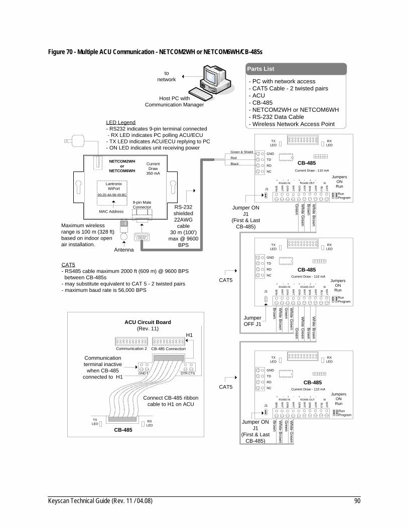
Keyscan Technical Guide (Rev. 11 / 04.08) 90
Figure 70 - Multiple ACU Communication - NETCOM2WH or NETCOM6WH/CB-485s
Brown
White B
rown
White G
reenG
reen
GND
RD
NC
TD
RXLED
TXLED
+ - + -
Current Draw - 110 mA
CB-485
Connect CB-485 ribbon cable to H1 on ACU
GND
RD
NC
TD
RXLED
TXLED
Current Draw - 110 mA
CB-485
GND
RD
NC
TD
RXLED
TXLED
Current Draw - 110 mA
CB-485
Brown
White B
rown
White G
reenG
reen
Brown
White B
rown
White G
reenG
reen
Brown
White Brow
n
White G
reenG
reen
- PC with network access - CAT5 Cable - 2 twisted pairs- ACU- CB-485- NETCOM2WH or NETCOM6WH- RS-232 Data Cable- Wireless Network Access Point
Parts List
Host PC withCommunication Manager
Jumper ONJ1
(First & Last CB-485)
Jumper OFF J1
Jumper ONJ1
(First & Last CB-485)
CAT5
RXLED
TXLED
CB-485
CB-485 Connection
H1
CTSGND T DTR
Communication terminal inactive
when CB-485 connected to H1
J1
J1
J1
CAT5
to network
BRN
WH
T
GR
N
WH
T
BR
N
WH
T
GR
N
WH
T
BLU
WH
T
RS485 IN RS485 OUT M+ - + - + - + -
BR
N
WH
T
GR
N
WH
T
BR
N
WH
T
GR
N
WH
T
BLU
WH
T
RS485 IN RS485 OUT M+ - + - + - + -
BRN
WH
T
GR
N
WH
T
BR
N
WH
T
GR
N
WH
T
BLU
WH
T
RS485 IN RS485 OUT M+ - + - + - + -
JumpersONRun
RunProgram
JumpersONRun
RunProgram
JumpersONRun
RunProgram
CAT5- RS485 cable maximum 2000 ft (609 m) @ 9600 BPS between CB-485s- may substitute equivalent to CAT 5 - 2 twisted pairs- maximum baud rate is 56,000 BPS
Maximum wireless range is 100 m (328 ft) based on indoor open air installation.
9-pin MaleConnector
NETCOM2WH or
NETCOM6WH
Current Draw
350 mA
MAC Address
Lantronix WiPort
00-20-4A-96-49-BC
Green & Shield
Red
Black
RS-232 shielded22AWG
cable30 m (100')
max @ 9600 BPS
LED Legend- RS232 indicates 9-pin terminal connected - RX LED indicates PC polling ACU/ECU- TX LED indicates ACU/ECU replying to PC- ON LED indicates unit receiving power
Antenna
ACU Circuit Board(Rev. 11)
Communication 2

Keyscan Technical Guide (Rev. 11 / 04.08) 91
Figure 71 - Multiple ACU Communication - NETCOM2WH or NETCOM6WH/CPB-10s
Connect CPB10 ribbon cable to H1 on ACU
- PC with network connection - 22 AWG 4 conductors shielded cable- ACU- CPB-10- NETCOM2WH or NETCOM6WH - RS232 Data Cable- Wireless network access point
Parts List
Brown & White not used. Tape back separately.
Jumper ONJ1
(First & Last CPB10)
Jumper OFF J1
Jumper ONJ1
(First & Last CPB10)
Green &
Shield
Red
Black
RX LEDTX LED
CPB-10
CB-485 Connection
H1
CTSGND T DTR
Communication terminal inactive when CPB-10 connected to
H1
ACU Circuit Board(Rev. 11)
RXLED
TXLED
GND TD RD DCD T BGND R DTR CTS
Current Draw40 mA
J1
RXLED
TXLED
GND TD RD DCD T BGND R DTR CTS
Current Draw40 mA
CPB-10
J1
RXLED
TXLED
GND TD RD DCD T BGND R DTR CTS
Current Draw40 mA
J1
GN
DR T B
Shield
GN
DR T B
GN
D R T B
GN
DR T B
Shield
Tape back shield
EIA/TIA 562 Signal
CPB-10- supports parallel and star communication (diagram shows CPB-10 in parallel communication)- maximum distance 1st to last CPB-10 - 4000 ft (1219 m) - maximum distance between CPB-10s - 2000 ft (609 m)- see MISCOMM2 for inter-building communication on a CPB-10 communication loop
LegendGND = GroundR = RxT = TxB = Busy Line
CPB-10
CPB-10
PC withCommunication
Manager
RS-23222 AWG shielded cable100 FT (30 m) maximum
@ 9600 BPS
to network
LED Legend- RS232 indicates 9-pin terminal connected - RX LED indicates PC polling ACU/ECU- TX LED indicates ACU/ECU replying to PC- ON LED indicates unit receiving power
Maximum wireless range is 100 m (328 ft) based on indoor open
air installation.
9-pin MaleConnector
NETCOM2WH or
NETCOM6WH
Current Draw
350 mA
MAC Address
Lantronix WiPort
00-20-4A-96-49-BC
Antenna
Communication 2

Keyscan Technical Guide (Rev. 11 / 04.08) 92
Figure 72 - Multiple ACU Communication - NETCOM2WH or NETCOM6WH / 1 per ACU
- PC with network connection - ACU- NETCOM2WH or NETCOM6WH - RS232 Data Cable- Wireless Network Access Point
Parts List
Brown & White not used. Tape back
separately.
Green &
Shield
Red
Black
Host PC withCommunication
Manager
RS-23222 AWG shielded cable100 FT (30 m) maximum
@ 9600 BPS
to network
12VDC Power Adaptor
LED Legend- RS232 indicates 9-pin terminal connected - RX LED indicates PC polling ACU/ECU- TX LED indicates ACU/ECU replying to PC- ON LED indicates unit receiving power
CB-485 Connection
Short with jumper.
ACUCircuit Board
(Rev. 11)
Brown & White not used. Tape back
separately.
Green &
Shield
Red
Black
CB-485 Connection
Short with jumper.
ACUCircuit Board
(Rev. 11)
GND TD RDDCDDTRCTS
GNDTD RDDCDDTRCTSMaximum wireless range is 100 m (328 ft) based on indoor open air installation.
9-pin MaleConnector
NETCOM2WH or
NETCOM6WH
Current Draw
350 mA
MAC Address
Lantronix WiPort
00-20-4A-96-49-BC
Antenna
12VDC Power Adaptor
Maximum wireless range is 100 m (328 ft) based on indoor open air installation.
9-pin MaleConnector
NETCOM2WH or
NETCOM6WH
Current Draw
350 mA
MAC Address
Lantronix WiPort
00-20-4A-96-49-BC
Antenna
Communication 2
Communication 2

Keyscan Technical Guide (Rev. 11 / 04.08) 93
Figure 73 - Multiple ACU Communication - CB-485M/CB-485/MC33H
Brown
White Brow
n
White G
reenG
reen
GND
RDModem
ChipNC
TD
RXLED
TXLED
Current Draw360 mA
CB-485M
Connect CB-485 ribbon cable to H1 on ACU
GND
RD
NC
TD
RXLED
TXLED
Current Draw - 110 mA
CB-485
GND
RD
NC
TD
RXLED
TXLED
Current Draw - 110 mA
CB-485
Brown
White Brow
n
White G
reenG
reen
Brown
White B
rown
White G
reenG
reen
Brown
White Brow
n
White G
reenG
reen
- PC - CAT5 Cable - 3 twisted pairs- ACU- CB-485- CB485M- MC33H Modem- RS232 Modem Cable- Dedicated Analog Phone Line
Parts List
PC withCommunication
Manager
Jumper ONJ1
(First & Last CB-485)
Jumper OFF J1
Jumper ONJ1
(First & Last CB-485)
CAT5
CAT5- RS485 cable maximum 2000 ft (609 m) @ 9600 BPS between CB-485s- may substitute equivalent to CAT 5 - 3 twisted pairs- maximum baud rate is 19,200 with CB-485M
RXLED
TXLED
CB-485
CB-485 Connection
H1
CTSGND T DTR
Communication terminal inactive
when CB-485 connected to
H1
ACU Circuit Board(Rev. 11)
J1
J1
J1
CAT5
connect to analog phone
line
RJ11Terminal
to Com Port
RJ 11 Terminal- connect to analog phone line
12 VDCAdaptor
(plug on reverse side)
RS232 ModemCable
MC33H Modem
BRN
WH
T
GR
N
WH
T
BR
N
WH
T
GR
N
WH
T
BLU
WH
T
RS485 IN RS485 OUT M+ - + - + - + -
BRN
WH
T
GR
N
WH
T
BR
N
WH
T
GR
N
WH
T
BLU
WH
T
RS485 IN RS485 OUT M+ - + - + - + -
BRN
WH
T
GR
N
WH
T
BR
N
WH
T
GR
N
WH
T
BLU
WH
T
RS485 IN RS485 OUT M+ - + - + - + -
JumpersONRun
RunProgram
JumpersONRun
RunProgram
JumpersONRun
RunProgram
RILED
DCDLED
BlueW
hite BlueBlueW
hite Blue
BlueW
hite Blue
Communication 2
MC33H jumper - DCE

Keyscan Technical Guide (Rev. 11 / 04.08) 94
Figure 74 - Multiple ACU Communication - MC9600/CPB-10/MC33H
Important - see Communication Jumper J16 for Multiple ACUs with Modem/CPB-10 Configuration on next page.
Connect CPB10 ribbon cable to H1 on ACU
- PC (with serial port) - 22 AWG 4 conductors shielded cable- ACU- CPB-10- RS232 Modem Cable- MC9600 Modem- MC33H Modem- Dedicated Analog Phone Line
Parts List
to ComPort
PC withCommunication
Manager
Jumper ONJ1
(First & Last CPB10)
Jumper OFF J1
Jumper ONJ1
(First & Last CPB10)
Green
&Shield
Red
Black
RX LEDTX LED
CPB-10
CB-485 Connection
H1
CTSGND T DTR
Communication terminal inactive when CPB-10 connected to
H1
ACU Circuit Board(Rev. 11)
RXLED
TXLED
GND TD RD DCD T BGND R DTR CTS
Current Draw40 mA
J1
RXLED
TXLED
GND TD RD DCD T BGND R DTR CTS
Current Draw40 mA
CPB-10
J1
RXLED
TXLED
GND TD RD DCD T BGND R DTR CTS
Current Draw40 mA
J1
GN
DR T B
Shield
GN
DR T B
GN
D R T B
GN
DR T B
Shield
Tape back shield
EIA/TIA 562 Signal
CPB-10- supports parallel and star communication (diagram shows CPB-10 in parallel communication)- maximum distance 1st to last CPB-10 - 4000 ft (1219 m) - maximum distance between CPB-10s - 2000 ft (609 m)- see MISCOMM2 for inter-building communication on a CPB-10 communication loop
LegendGND = GroundR = RxT = TxB = Busy Line
CPB-10
CPB-10
White
Brow
n
RJ 11 Terminal- connect to analog phone line
12 VDCAdaptor
(plug on reverse side)
RS232 ModemCable
MC33H Modem
Set jumper to DTE
Current Draw 300 mA
GND
MC9600
RX TX MRRIDCD
DCE
-+12VDC
DTR
DTE
9-pin MaleConnector
to 12VDC ACU power supply-
+
to analogphone line RJ 11
Terminal
Communication 2
MC33H jumper - DCE

Keyscan Technical Guide (Rev. 11 / 04.08) 95
Communication Jumper J16 for Multiple ACUs with CB-485M/CB-485 Configuration On the ACU that is connected to the CB-485M (modem), set the main circuit board's communication to 9600 (pins 1 & 2) or 19,200 (pin 1) Keyscan Modem. On the remaining ACUs connected by CB-485s, set communication to the equivalent Keyscan serial baud rate.
MainCircuitBoard
CB-485
MainCircuitBoard
CB-485
MainCircuitBoard
J16 - Pins 1 & 2ON
J16 - Pins 1 & 2OFF
J16 - Pins 1 & 2OFF
J161 2 3 4 5 6 7 8
J161 2 3 4 5 6 7 8
J161 2 3 4 5 6 7 8
CB-485M ACU ACU ACU
CB-485M @ 9600 BPS
MainCircuitBoard
CB-485
MainCircuitBoard
CB-485
MainCircuitBoard
J16 - Pin 1ON
J16 - Pin 2ON
J16 - Pin 2ON
J161 2 3 4 5 6 7 8
J161 2 3 4 5 6 7 8
J161 2 3 4 5 6 7 8
CB-485M ACU ACU ACU
CB-485M @ 19200 BPS
Communication Jumper J16 for Multiple ACUs with Modem/CPB-10 Configuration On the ACU that is connected to the modem, set the main circuit board's communication to 9600 Keyscan Modem. On the remaining ACUs connected by CPB-10s, set communication to 9600 Keyscan Serial.
CPB-10
MainCircuitBoard
CPB-10
MainCircuitBoard
CPB-10
MainCircuitBoard
J16 - Pins 1 & 2ON
J16 - Pins 1 & 2OFF
J16 - Pins 1 & 2OFF
J161 2 3 4 5 6 7 8
J161 2 3 4 5 6 7 8
J161 2 3 4 5 6 7 8
Modem
ACU ACU ACU

Keyscan Technical Guide (Rev. 11 / 04.08) 96
Communication LEDs The CA 230, CA 4300, CA 8300, EC 1300, EC 2300, CB-485, and CPB-10 have on-board communication LEDs for diagnostic and troubleshooting. The table below outlines the LED and its diagnostic function. When calling Keyscan for technical support, indicating the state of the LED will assist our technicians in isolating potential difficulties.
Table 11 - Communication LEDs
All CA & EC boards
LED State of LED
Green LED – TD Flashing: Normal – Replying to PC Not Illuminated – No response Illuminated – Power or wiring fault
Red LED – RD Flashing: Normal – Polling PC Not Illuminated – No response Illuminated – Power or wiring fault
CB-485/CPB-10
LED State of LED
Green LED – TX Flashing: Normal – Replying to PC Not Illuminated – No response Illuminated – Power or wiring fault
Red LED – RX Flashing: Normal – Polling PC Not Illuminated – No response Illuminated – Power or wiring fault
Red LED – B Not Illuminated – Normal Illuminated – One of the following conditions exists: a) Alarm in queue b) Communication Manager's Unit Diagnostics communicating with PC c) Modem is dialing out

Keyscan Technical Guide (Rev. 11 / 04.08) 97
Figure 75 - Communication LEDs CA & EC boards
CB 485 Connection
Com
mon
Ret
urn
9 10 11 12 13 14 15 16 Communication
GNDTD RDDCD DTRCTS
TD RD
Clock Chip
Communication 2
/ Alarm Inputs N.C.
CommunicationLEDs
U4
Figure 76 - Communication LEDs on CB-485
GND
CB-485
J1
RXLED
TXLED
TD
RD
NC
BRNWHTGRN WHT BRNWHTGRN WHT BLU WHTRS485 IN RS485 OUT M
+ - + - + - + -
BLED
Communication LEDs
Figure 77 - Communication LEDs on CPB-10
TGnd TD RD DCD Gnd R B DTR CTS
TX LED B LED RX LED
Communication LEDs

Keyscan Technical Guide (Rev. 11 / 04.08) 98
Power-up and Test Voltages
Power Supply Specifications The power supply for the ACUs and ECUs is a dual power supply with 2 linear DC outputs. Each output is rated at 12VDC – 1.2 Amp.
Wiring Connections Before connecting power to the ACU, be sure to observe the following points:
• check the cable and wire connections • ensure no short circuits exist when measuring voltages • verify the DC polarity is correct for all equipment
Following the above guidelines ensures each device will function properly and not be damaged.
System Power-up Steps 1. Connect 12VDC power, Power Fail Detect, and Earth Ground to the ACU circuit board. 2. Connect backup battery. 3. Connect 2 x 16V 40VA or 16.5V 37VA Class 2 transformers. Must be CSA/UL approved
transformers. 4. Repeat battery and transformer connections for additional power supplies. 5. After power is applied to the ACU, check ACU voltage test points. Refer to Table 12 and Table 13. 6. Load factory default settings by momentarily shorting the 2 pins on Clear Memory Jumper J1 on
the ACU main circuit board while the ACU is powered. Do not short Jumpers J6 or J8 otherwise the factory default settings will not load properly and result in communication difficulties.
7. When all voltage and current measurements are verified as correct, you are ready to upload the database to the ACUs. Refer to the Client on-line help.
Notes ACU's DC power input x 2.
For battery circuit and auxiliary power output to function, 2 transformers must be connected.
If any reader exceeds 150mA, connect reader red wire directly to separate DC supply's positive (+) terminal.
For monitoring an auxiliary power failure, the Auxiliary Power Fail Output terminal can be connected to an Auxiliary Input on the ACU's main circuit board.
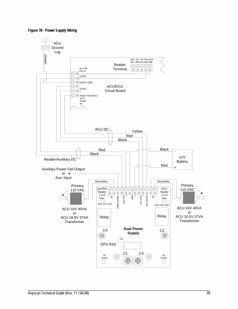
Keyscan Technical Guide (Rev. 11 / 04.08) 99
Figure 78 - Power Supply Wiring
Aux RdrPwr In
12VDC
Power Fail DetectACUPowerIN
+
-
EARTH GND
12VDC+
-
AC - Aux 12V
Alarm O
utput
Batt
Power Fail
Reader Terminal
Primary110 VAC
ACU 16V 40VAor
ACU 16.5V 37VATransformer
Primary110 VAC
ACU 16V 40VAor
ACU 16.5V 37VATransformer
ACUSupply1.2 A max
Aux/RdrSupply1.2 A max
+ - + AC- ACU
12V
+
12VBattery
+
-Black
Red
Green
ACU Ground
Lug
U1
C2C4
DPS R2A
AUX 12V LED
Dual Power Supply
Relay Relay
ACU 12V LED
Secondary Secondary
ACU/ECUCircuit Board
ACPower
ACPower
Auxiliary Power Fail Outputto
Aux. Input
Reader/Auxiliary DC
ACU DC
BlackRed
Yellow
BlackRed
LEDBrn
D1Wht
D0Grn
PwrRed
GndBlk
C1 C3
Keyscan Technical Guide (Rev. 11 / 04.08) 100
Controller Voltage Test Points The following table outlines the correct voltages for the test points on the ACU main circuit boards. Be sure to review the notes opposite the appropriate voltage test points to comply with proper measuring techniques or special circumstances.
Voltmeter Connections • Voltmeter set to VDC • V-Ω to test points • Com to ground lug in ACU enclosure
Table 12 - Controller Test Points - Voltages
Board Test Point Voltage Instructions/Notes
Reader Terminal
D1 WHT (+) 5VDC White data 1
D0 GRN (+) 5VDC Green data 0
PWR RED (+) 12VDC Red DC Out
Reader Power Input (+) 13.5VDC Measure the + contact
ACU Power Input (+) 13.5VDC Measure the + contact
TP1 (+) 5VDC
TP2 (+) 12VDC
TP3 (-) 11VDC TP3 voltage (-) 11VDC
TP4 (+) 5VDC Measure TP4 for 1 minute. If voltage constant at 5VDC, board processor OK If voltage fluctuates or drops to 0VDC, board processor faulty.
TP5 (+) 5VDC
B1 – Lithium Battery (+) 3VDC Voltmeter V-Ω contact to metallic circle of lithium battery
Input Points
Input points with open circuit (+) 5VDC
Input points shorted to common return
0VDC
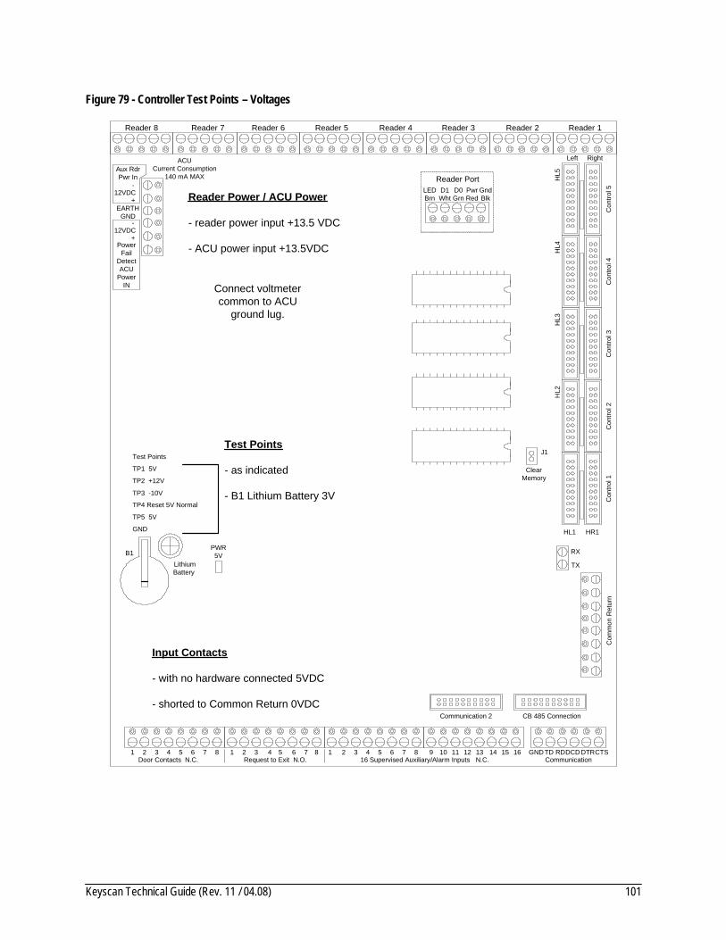
Keyscan Technical Guide (Rev. 11 / 04.08) 101
Figure 79 - Controller Test Points – Voltages
TP2 +12V
Aux RdrPwr In
12VDC
PowerFail
DetectACU
PowerIN
PWR 5V
LithiumBattery
B1
TP3 -10V
+
-
EARTHGND
12VDC+
-
TP1 5V
CB 485 Connection
ClearMemory
J1
TP4 Reset 5V Normal
Reader 1Reader 2Reader 3
Reader PortLEDBrn
D1Wht
D0Grn
PwrRed
GndBlk
TX
RX
Con
trol 1
Con
trol 2
Con
trol 3
Con
trol 4
Con
trol 5
HR1HL1
Com
mon
Ret
urn
HL2
HL3
HL4
HL5
1 Door Contacts N.C.
2 3 4 1 2 3 4 Request to Exit N.O.
1 2 3 4 5 6 16 Supervised Auxiliary/Alarm Inputs N.C.
7 8 9 10 11 12 13 14 15 16 Communication
GNDTD RDDCD DTRCTS5 6 7 85 6 7 8
Reader 4Reader 5Reader 6Reader 7Reader 8
Left Right
Communication 2
TP5 5V
GND
Test Points
ACUCurrent Consumption
140 mA MAX
Reader Power / ACU Power
- reader power input +13.5 VDC
- ACU power input +13.5VDC
Test Points
- as indicated
- B1 Lithium Battery 3V
Input Contacts
- with no hardware connected 5VDC
- shorted to Common Return 0VDC
Connect voltmeter common to ACU
ground lug.

Keyscan Technical Guide (Rev. 11 / 04.08) 102
Controller Test Points – Communication Terminal The following table outlines the correct voltages for the test points on the communication terminal on the ACU, the CB-485 or the CPB-10.
Table 13 – Communication Voltage Test Points
Communication Test Point Voltage Instructions/Notes
ACU Communication Terminal
RS-232 connected to ACU
Connect Voltmeter COM to GND on ACU Communication terminal block or green on data cable.
GND
TD (-) 9VDC TD is an ACU generated voltage
RD (-) 10VDC RD is a PC generated voltage
DCD Used for modems only
DTR n/a
CTS n/a
CB-485
At all ACUs
Connect Voltmeter COM to GND on ACU Communication terminal block or green on data cable. Remove jumper to plug in ribbon.
GND .
GRN+ 3.5VDC
WHT- 1.5VDC
BRN+ 3.5VDC
WHT- 1.5VDC
TD (-) 7VDC TD is an ACU generated voltage
RD (-) 7VDC RD is a PC generated voltage
Important When a CB-485 is used, the Communication terminal block on the ACU main circuit board is in-active. Measure only the CB-485 Communication terminal.
CPB 10
At all ACUs
Connect Voltmeter COM to GND on ACU Communication terminal block or green on data cable. Remove jumper to plug in ribbon.
GND .
R 12.8VDC
T 12.8VDC
TD (-) 11VDC TD is an ACU generated voltage
RD (-) 10VDC RD is a PC generated voltage
Important When a CPB-10 is used, the Communication terminal block on the ACU main circuit board is in-active. Measure only the CPB-10 Communication terminal.

Keyscan Technical Guide (Rev. 11 / 04.08) 103
Figure 80 – ACU Communication Test Points
CB 485 Connection
9 10 11 12 13 14 15 16 Communication
GNDTD RDDCD DTRCTS
Communication 2
Figure 81 - CB-485 Communication Test Points
ACU Circuit Board
CB-485 Connection
H1
red stripeRibbon cable connects
from CB-485 tomain circuit board - H1
Communication terminal inactive
when CB-485 connected to H1
CTS
Communication 2
15141312111098
GND
CB-485
J1
RXLED
TXLED
TD
RD
NC
BRNWHTGRNWHT BRNWHTGRNWHT BLUWHTRS485 IN RS485 OUT M
+ - + - + - + -
Current Draw - 110 mA
RunProgram

Keyscan Technical Guide (Rev. 11 / 04.08) 104
Figure 82 - CPB-10 Communication Test Points
GND TD RD DCD GND R T B DTR CTS
CPB-10 Circuit Board - Communication Terminal
Main Circuit Board
CPB-10 Terminal
CB-485 Connection
H1
red stripe
CPB-10Circuit Board
Ribbon cable connectsfrom CPB-10 to
main circuit board - H1
Communication terminal inactive when CPB-10
connected to H1
CTS
Communication 2
15141312111098
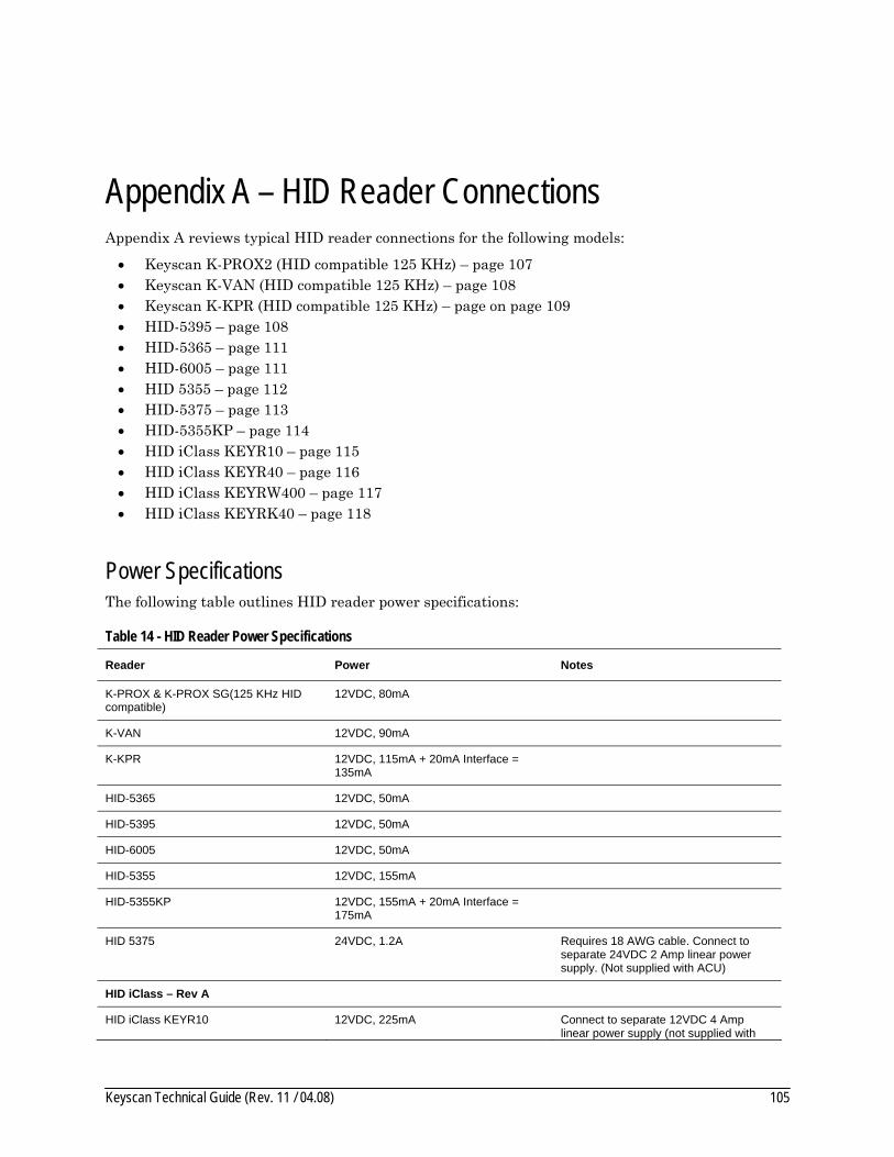
Keyscan Technical Guide (Rev. 11 / 04.08) 105
Appendix A – HID Reader Connections Appendix A reviews typical HID reader connections for the following models:
• Keyscan K-PROX2 (HID compatible 125 KHz) – page 107 • Keyscan K-VAN (HID compatible 125 KHz) – page 108 • Keyscan K-KPR (HID compatible 125 KHz) – page on page 109 • HID-5395 – page 108 • HID-5365 – page 111 • HID-6005 – page 111 • HID 5355 – page 112 • HID-5375 – page 113 • HID-5355KP – page 114 • HID iClass KEYR10 – page 115 • HID iClass KEYR40 – page 116 • HID iClass KEYRW400 – page 117 • HID iClass KEYRK40 – page 118
Power Specifications The following table outlines HID reader power specifications:
Table 14 - HID Reader Power Specifications
Reader Power Notes
K-PROX & K-PROX SG(125 KHz HID compatible)
12VDC, 80mA
K-VAN 12VDC, 90mA
K-KPR 12VDC, 115mA + 20mA Interface = 135mA
HID-5365 12VDC, 50mA
HID-5395 12VDC, 50mA
HID-6005 12VDC, 50mA
HID-5355 12VDC, 155mA
HID-5355KP 12VDC, 155mA + 20mA Interface = 175mA
HID 5375 24VDC, 1.2A Requires 18 AWG cable. Connect to separate 24VDC 2 Amp linear power supply. (Not supplied with ACU)
HID iClass – Rev A
HID iClass KEYR10 12VDC, 225mA Connect to separate 12VDC 4 Amp linear power supply (not supplied with

Keyscan Technical Guide (Rev. 11 / 04.08) 106
Reader Power Notes
(HID label – 6100AKN0010 – Rev A) ACU kit) for CA8000 when connecting 8 readers. For all other ACU models connect power (red) of iClass reader directly to DPS-12 power.
HID iClass KEYR40 (HID label – 6120AKN0010 – Rev A)
12VDC, 260mA See note HID iClass KEYR10 – Rev A
HID iClass KEYRK40 (HID label – 6130AKN001000 – Rev A)
12VDC, 260mA + 20mA Interface = 280mA
See note HID iClass KEYR10 – Rev A
HID iClass KEYRW400 (HID label 6121AKN0010 – Rev A)
12VDC, 260mA See note HID iClass KEYR10 – Rev A
HID iClass – Rev B
HID iClass KEYR10 (HID label – 6100BKN0010 – Rev B)
12VDC, 75mA
HID iClass KEYR40 (HID label – 6120BKN0010 – Rev B)
12VDC, 75mA
HID iClass KEYRK40 (HID label – 6130BKN001000 – Rev B)
12VDC, 244mA + 20mA Interface = 264mA
Connect to separate 12VDC 4 Amp linear power supply (not supplied with ACU kit) for CA8000 when connecting 8 readers. For all other ACU models connect power (red) of iClass reader directly to DPS-12 power.
HID iClass KEYRW400 (HID label – 6121BKN0010 – Rev B)
12VDC, 75mA
Installation Notes on Proximity Readers Do not run reader cables in same conduit with AC power or signal cables.
Keep reader cables at a minimum distance of 12 inches or 30 centimetres from AC, computer data, telephone data, or electric lock device cables.
Do not install readers within 3.5 feet or 1.1 metres of computer CRTs.
Do not install readers in areas where broad spectrum EMI noise may be present. Devices such as motors, pumps, generators, and AC switching relays can create EMI noise.
Readers mounted on a metal surface can reduce the read range.
See HID manual for full operational details and recommendations.
Important The following diagrams illustrate HID readers with dual LEDs. On models 5365, 5395, and 6005 do not use the brown wire with "00" LED. If readers are single LED type "06", substitute the brown wire in place of the orange wire.
• S16 – 5 ON dual LED = 00 • S16 – 5 OFF single LED = 06

Keyscan Technical Guide (Rev. 11 / 04.08) 107
Figure 83 - Keyscan K-PROX2 (125 KHz HID compatible)
LED (Brow
n)D
1 (White)
D0 (G
reen)
PW
R (R
ed)G
ND
(Black)
Shield not connected.
Isolate with electrical tape. 3 pair shielded
22 AWG 500' maximum
LEDBRN
D1WHT
D0GRN
PWRRED
GNDBLK
Shield
ACU Ground Lug
D1 (W
hite)
D0 (G
reen)
PWR
(Red)
GN
D (B
lack)
LED (Brow
n)
Reader port on ACU main circuit board
KEYSCAN
Orange not used.Isolate with electrical
tape.
Blue - used for pre-alert option or isolate with
electrical tape.
KEYSCAN
K-PROX2 shown with switch plate.
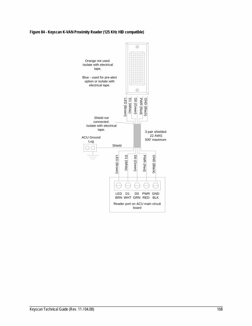
Keyscan Technical Guide (Rev. 11 / 04.08) 108
Figure 84 - Keyscan K-VAN Proximity Reader (125 KHz HID compatible)
LED (Brow
n)D
1 (White)
D0 (G
reen)
PW
R (R
ed)G
ND
(Black)
Shield not connected.
Isolate with electrical tape. 3 pair shielded
22 AWG 500' maximum
LEDBRN
D1WHT
D0GRN
PWRRED
GNDBLK
Shield
ACU Ground Lug
D1 (W
hite)
D0 (G
reen)
PW
R (R
ed)
GN
D (Black)
LED (Brow
n)
Reader port on ACU main circuit board
Orange not used.Isolate with electrical
tape.
Blue - used for pre-alert option or isolate with
electrical tape.
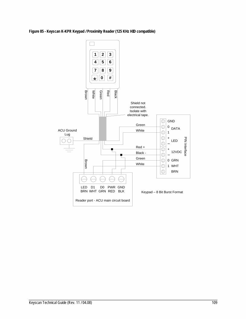
Keyscan Technical Guide (Rev. 11 / 04.08) 109
Figure 85 - Keyscan K-KPR Keypad / Proximity Reader (125 KHz HID compatible)
Brown
White
Green
Red
Black
Shield not connected.Isolate with
electrical tape.
LEDBRN
D1WHT
D0GRN
PWRRED
GNDBLK
Shield
ACU Ground Lug
White
Black -
Brow
n
Reader port - ACU main circuit board
Red +
PIN
Interface
GND
1
0
+LED
+12VDC
0
1 WHT
GRN
DATA
BRN
Green
White
Green
1 2 3
4 5 6
7 8 9
0* #
Keypad – 8 Bit Burst Format
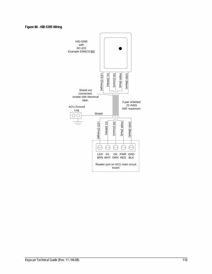
Keyscan Technical Guide (Rev. 11 / 04.08) 110
Figure 86 - HID-5395 Wiring
LED
(Orange)
D1 (W
hite)
D0 (G
reen)
PW
R (R
ed)
GN
D (B
lack)
Shield notconnected.
Isolate with electricaltape. 3 pair shielded
22 AWG500' maximum
LEDBRN
D1WHT
D0GRN
PWRRED
GNDBLK
HID-5395with
00 LEDExample 5395CG100
Shield
ACU GroundLug
D1 (W
hite)
D0 (G
reen)
PW
R (R
ed)
GN
D (B
lack)
LED
(Orange)
Reader port on ACU main circuitboard
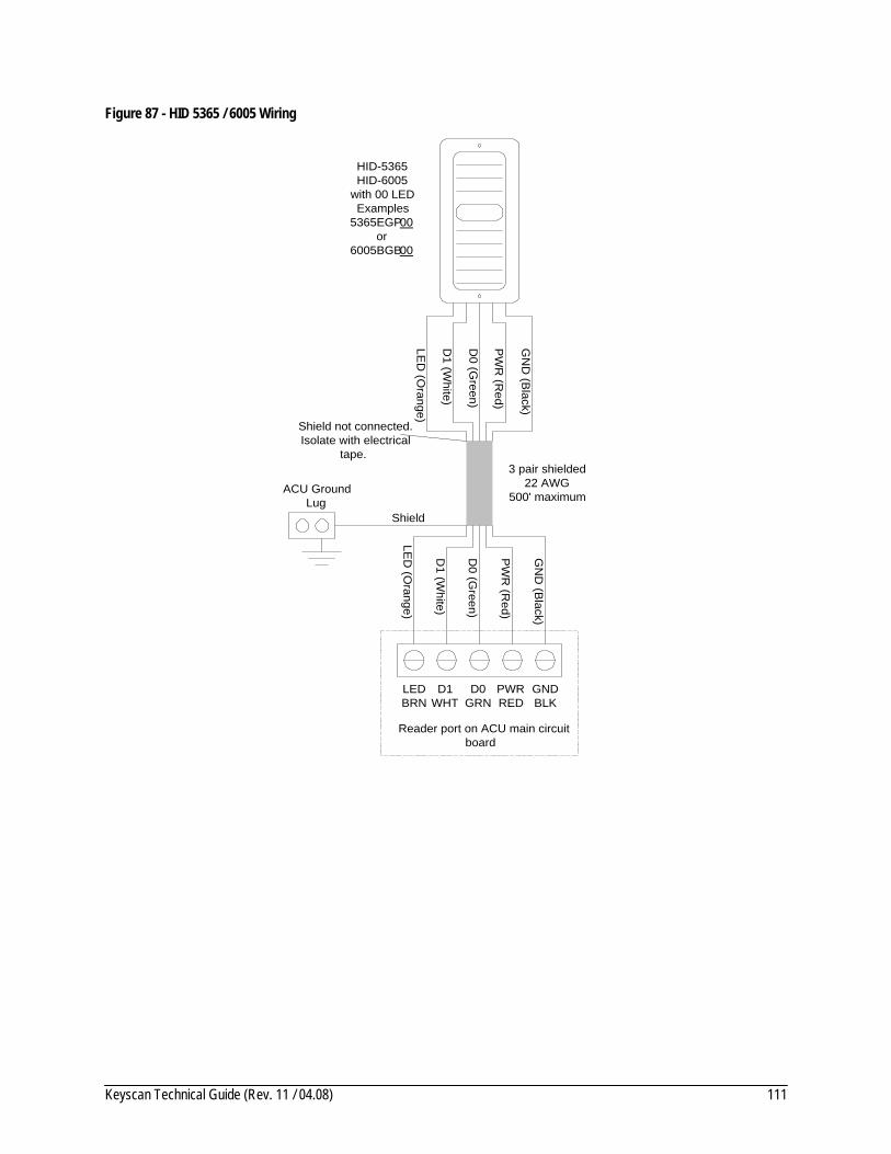
Keyscan Technical Guide (Rev. 11 / 04.08) 111
Figure 87 - HID 5365 / 6005 Wiring
LED
(Orange)
D1 (W
hite)
D0 (G
reen)
PW
R (R
ed)
GN
D (B
lack)
Shield not connected.Isolate with electrical
tape.3 pair shielded
22 AWG500' maximum
LEDBRN
D1WHT
D0GRN
PWRRED
GNDBLK
HID-5365HID-6005
with 00 LEDExamples
5365EGP00or
6005BGB00
Shield
ACU GroundLug
D1 (W
hite)
D0 (G
reen)
PW
R (R
ed)
GN
D (B
lack)
LED
(Orange)
Reader port on ACU main circuitboard
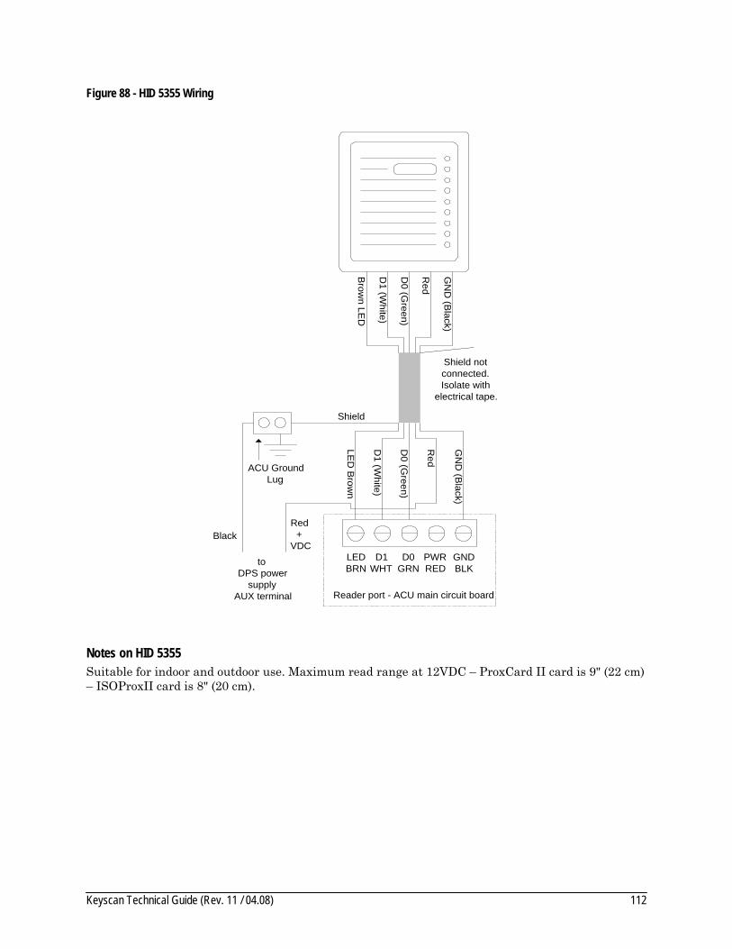
Keyscan Technical Guide (Rev. 11 / 04.08) 112
Figure 88 - HID 5355 Wiring
Brow
n LED
D1 (W
hite)
D0 (G
reen)
Red
GN
D (B
lack)
Shield notconnected.Isolate with
electrical tape.
LEDBRN
D1WHT
D0GRN
PWRRED
GNDBLK
Shield
ACU GroundLug
D1 (W
hite)
D0 (G
reen)
GN
D (B
lack)
LED
Brow
n
Reader port - ACU main circuit board
Red
Red+
VDCBlack
toDPS power
supplyAUX terminal
Notes on HID 5355 Suitable for indoor and outdoor use. Maximum read range at 12VDC – ProxCard II card is 9" (22 cm) – ISOProxII card is 8" (20 cm).
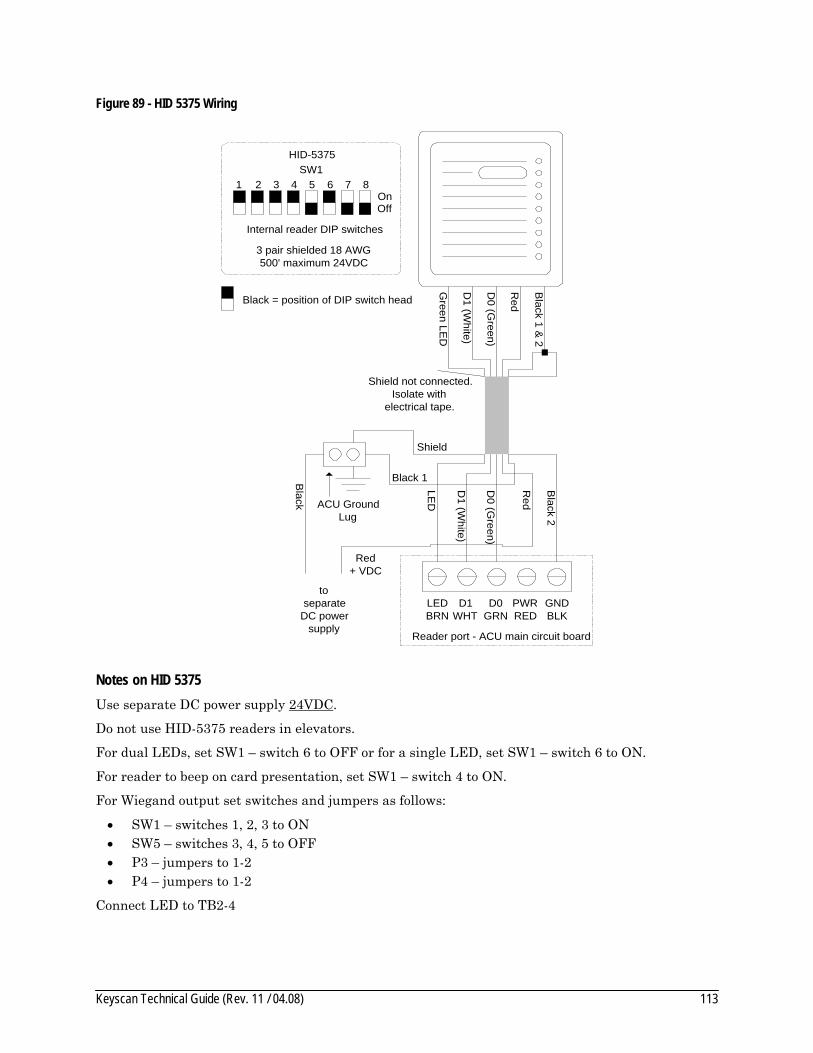
Keyscan Technical Guide (Rev. 11 / 04.08) 113
Figure 89 - HID 5375 Wiring
Green LE
D
D1 (W
hite)
D0 (G
reen)
Red
Black 1 &
2
Shield not connected.Isolate with
electrical tape.
LEDBRN
D1WHT
D0GRN
PWRRED
GNDBLK
Shield
ACU GroundLug
D1 (W
hite)
D0 (G
reen)
Red+ VDC
Black 2
LED
Reader port - ACU main circuit board
Red
Black
toseparate
DC powersupply
3 pair shielded 18 AWG500' maximum 24VDC
1 2 3 4 5 6 7 8OnOff
Internal reader DIP switches
HID-5375SW1
Black = position of DIP switch head
Black 1
Notes on HID 5375 Use separate DC power supply 24VDC.
Do not use HID-5375 readers in elevators.
For dual LEDs, set SW1 – switch 6 to OFF or for a single LED, set SW1 – switch 6 to ON.
For reader to beep on card presentation, set SW1 – switch 4 to ON.
For Wiegand output set switches and jumpers as follows:
• SW1 – switches 1, 2, 3 to ON • SW5 – switches 3, 4, 5 to OFF • P3 – jumpers to 1-2 • P4 – jumpers to 1-2
Connect LED to TB2-4

Keyscan Technical Guide (Rev. 11 / 04.08) 114
Figure 90 - HID 5355KP Wiring
Green LE
D
White
Green
Red
Black
Shield notconnected.Isolate with
electrical tape.
LEDBRN
D1WHT
D0GRN
PWRRED
GNDBLK
Shield
ACU GroundLug
White
Red+ VDC
Black -
LED
Reader port - ACU main circuit board
Red +
Black
toDPS power
supplyAUX
terminal
3 pair shielded 22 AWG500' maximum
1 2 3 4 5 6 7 8OnOff
Internal reader switches
HID-5355KPSW1
PIN
Interface
GND
1
0
+LED
+12VDC
0
1 WHT
GRN
DATA
BRN
Green
White
Green
1
4
7
*
2
5
8
0
3
6
9
#
Black = position of DIP switch head
Note on HID 5355 KP Reader/Keypad/LED ordered as 00 (4 bit burst) example 5355AGK00 (Red/Green colour)
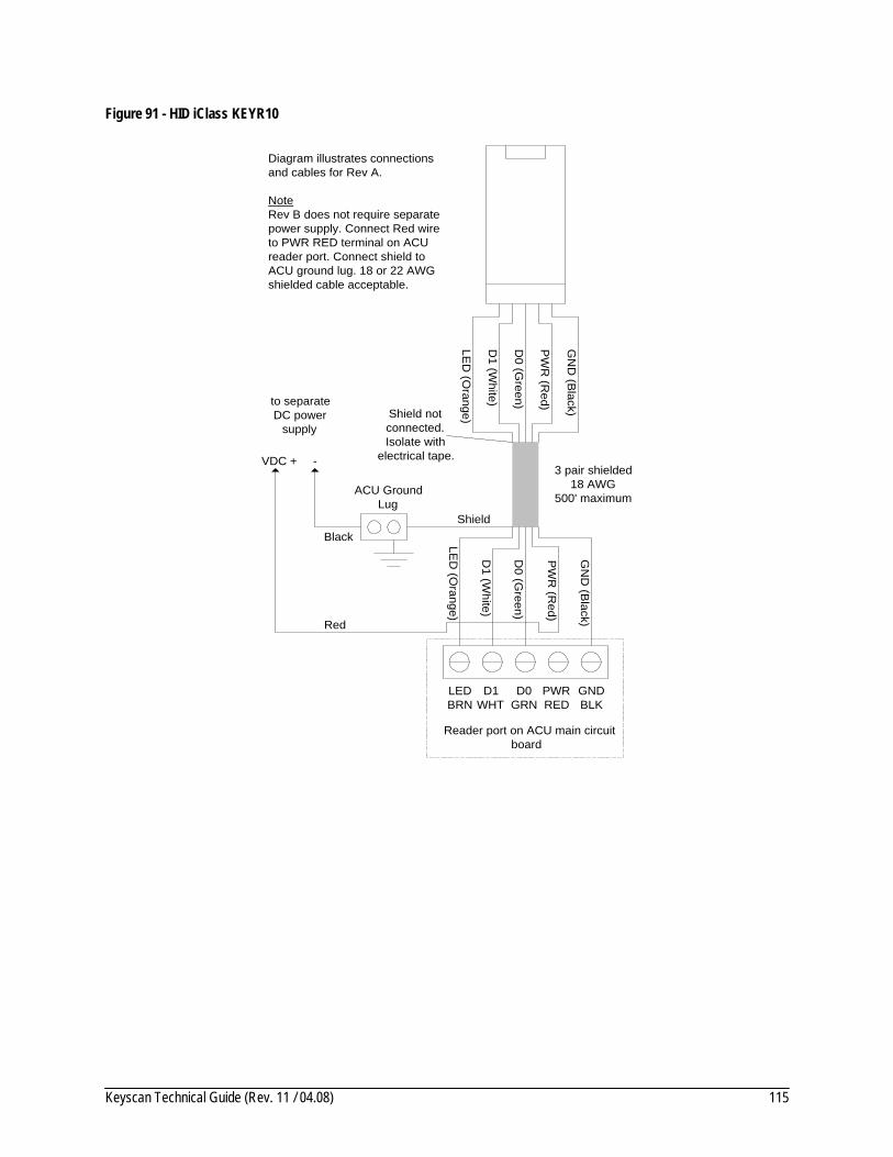
Keyscan Technical Guide (Rev. 11 / 04.08) 115
Figure 91 - HID iClass KEYR10
LED
(Orange)
D1 (W
hite)
D0 (G
reen)
PW
R (R
ed)
GN
D (B
lack)Shield notconnected.Isolate with
electrical tape.3 pair shielded
18 AWG500' maximum
LEDBRN
D1WHT
D0GRN
PWRRED
GNDBLK
Shield
ACU GroundLug
D1 (W
hite)
D0 (G
reen)
Red
GN
D (B
lack)
LED
(Orange)
Reader port on ACU main circuitboard
Black
VDC + -
to separateDC power
supply
PW
R (R
ed)
Diagram illustrates connectionsand cables for Rev A.
NoteRev B does not require separatepower supply. Connect Red wireto PWR RED terminal on ACUreader port. Connect shield toACU ground lug. 18 or 22 AWGshielded cable acceptable.
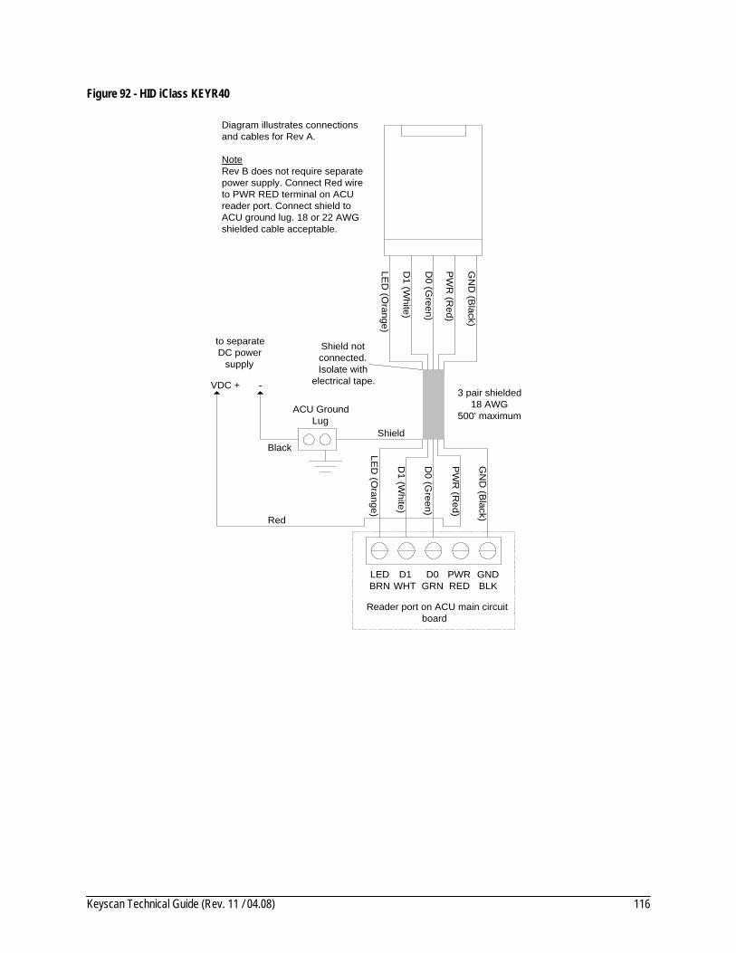
Keyscan Technical Guide (Rev. 11 / 04.08) 116
Figure 92 - HID iClass KEYR40
LED
(Orange)
D1 (W
hite)
D0 (G
reen)
PW
R (R
ed)
GN
D (B
lack)
Shield notconnected.Isolate with
electrical tape.3 pair shielded
18 AWG500' maximum
LEDBRN
D1WHT
D0GRN
PWRRED
GNDBLK
Shield
ACU GroundLug
D1 (W
hite)
D0 (G
reen)
Red
GN
D (B
lack)
LED
(Orange)
Reader port on ACU main circuitboard
Black
VDC + -
to separateDC power
supply
PW
R (R
ed)
Diagram illustrates connectionsand cables for Rev A.
NoteRev B does not require separatepower supply. Connect Red wireto PWR RED terminal on ACUreader port. Connect shield toACU ground lug. 18 or 22 AWGshielded cable acceptable.
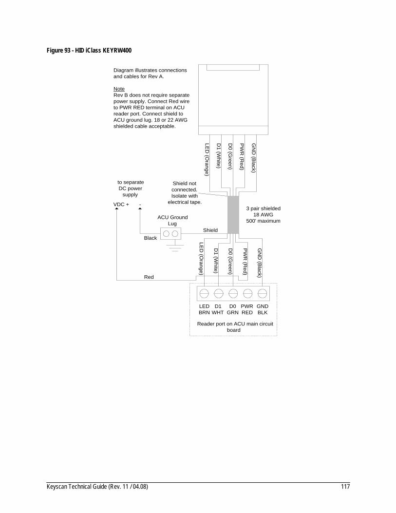
Keyscan Technical Guide (Rev. 11 / 04.08) 117
Figure 93 - HID iClass KEYRW400
LED
(Orange)
D1 (W
hite)
D0 (G
reen)
PW
R (R
ed)
GN
D (B
lack)
Shield notconnected.Isolate with
electrical tape.3 pair shielded
18 AWG500' maximum
LEDBRN
D1WHT
D0GRN
PWRRED
GNDBLK
Shield
ACU GroundLug
D1 (W
hite)
D0 (G
reen)
Red
GN
D (B
lack)
LED
(Orange)
Reader port on ACU main circuitboard
Black
VDC + -
to separateDC power
supply
PW
R (R
ed)
Diagram illustrates connectionsand cables for Rev A.
NoteRev B does not require separatepower supply. Connect Red wireto PWR RED terminal on ACUreader port. Connect shield toACU ground lug. 18 or 22 AWGshielded cable acceptable.
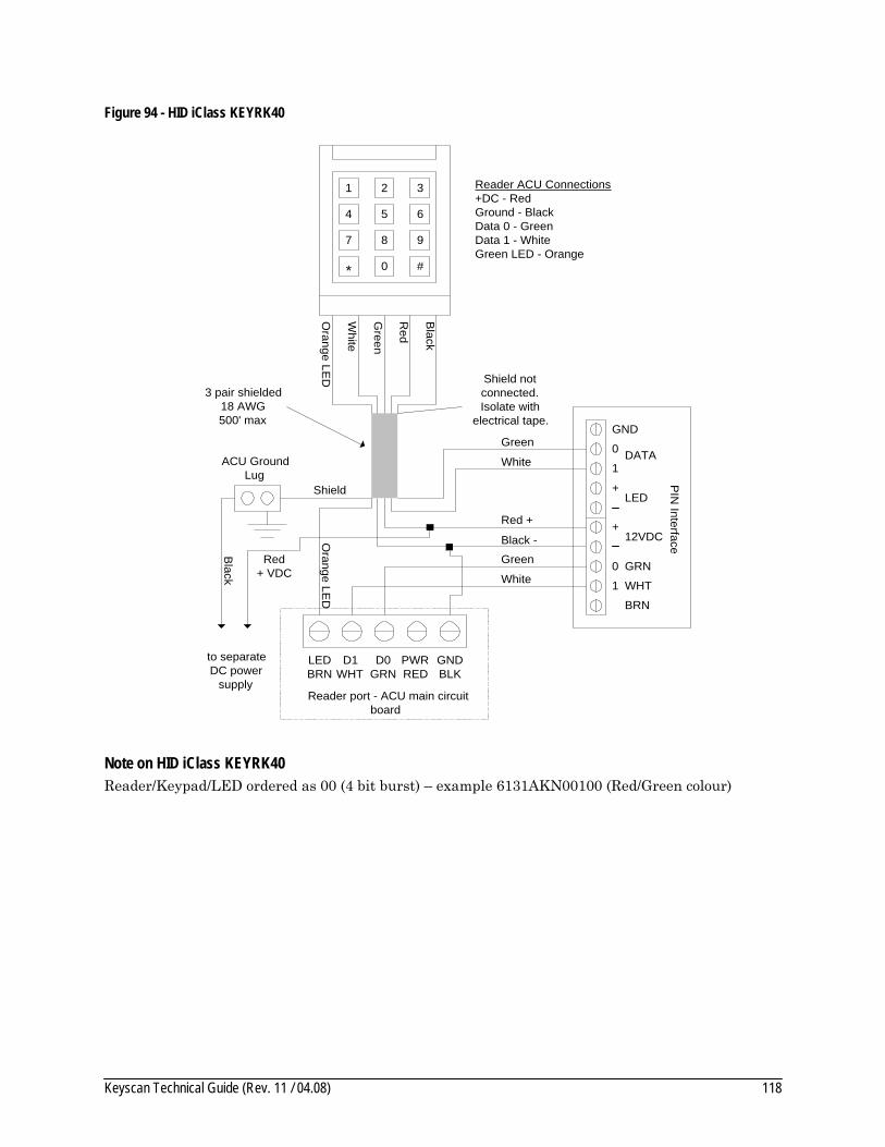
Keyscan Technical Guide (Rev. 11 / 04.08) 118
Figure 94 - HID iClass KEYRK40
Orange LE
D
White
Green
Red
Black
LEDBRN
D1WHT
D0GRN
PWRRED
GNDBLK
Shield
White
Red+ VDC
Black -
Red +
Black
PIN
Interface
GND
1
0
+LED
+12VDC
0
1 WHT
GRN
DATA
BRN
Green
White
Green
1 2 3
4 5 6
7 8 9
0* #
Orange LE
D
Reader ACU Connections+DC - RedGround - BlackData 0 - GreenData 1 - WhiteGreen LED - Orange
Shield notconnected.Isolate with
electrical tape.
to separateDC power
supply
3 pair shielded 18 AWG500' max
Reader port - ACU main circuitboard
ACU GroundLug
Note on HID iClass KEYRK40 Reader/Keypad/LED ordered as 00 (4 bit burst) – example 6131AKN00100 (Red/Green colour)
Keyscan Technical Guide (Rev. 11 / 04.08) 119
Appendix B – Indala Reader Connections Appendix B reviews typical Indala proximity reader connections for the following models:
• PX 603 – page 120 • PX 605 –page 120 • PX 610 – page 121 • PX 620 – page 122 • PXK 501 – page 123
Power Specifications The following table outlines Indala reader power specifications:
Table 15 - Indala Reader Power Specifications
Reader Power Notes
PX 603 12VDC, 100mA
PX 605 12VDC, 100mA
PX 610 12VDC, 150mA Requires additional power supply when connected to CA 8100 circuit board.
PX 620 24VDC, 1.2A Requires 18 AWG cable. Connect to separate 24VDC 2 Amp linear power supply. (Not supplied with ACU kit.)
PXK 501 12VDC, 100mA + 20mA Interface = 120mA
Current consumption includes interface circuit board
Installation Notes on Proximity Readers Do not run reader cables in same conduit with AC power or signal cables.
Keep reader cables at a minimum distance of 12 inches or 30 centimetres from AC, computer data, telephone data, or electric lock device cables.
Do not install readers within 3.5 feet or 1.1 metres of computer CRTs.
Do not install readers in areas where broad spectrum EMI noise may be present. Devices such as motors, pumps, generators, and AC switching relays can create EMI noise.
Readers mounted on a metal surface can reduce the read range. See the Indala manual for recommendations.
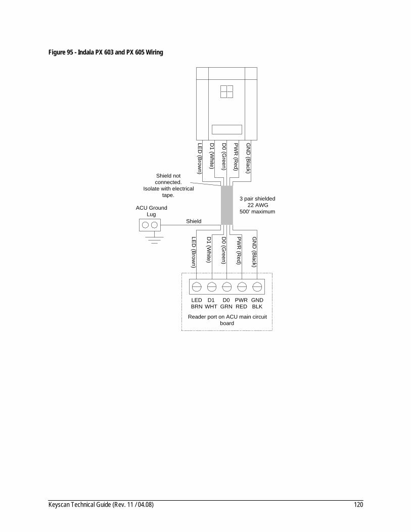
Keyscan Technical Guide (Rev. 11 / 04.08) 120
Figure 95 - Indala PX 603 and PX 605 Wiring
LED
(Brow
n)
D1 (W
hite)
D0 (G
reen)
PW
R (R
ed)
GN
D (B
lack)
Shield notconnected.
Isolate with electricaltape. 3 pair shielded
22 AWG500' maximum
LEDBRN
D1WHT
D0GRN
PWRRED
GNDBLK
Shield
ACU GroundLug
D1 (W
hite)
D0 (G
reen)
PW
R (R
ed)
GN
D (B
lack)
LED
(Brow
n)
Reader port on ACU main circuitboard
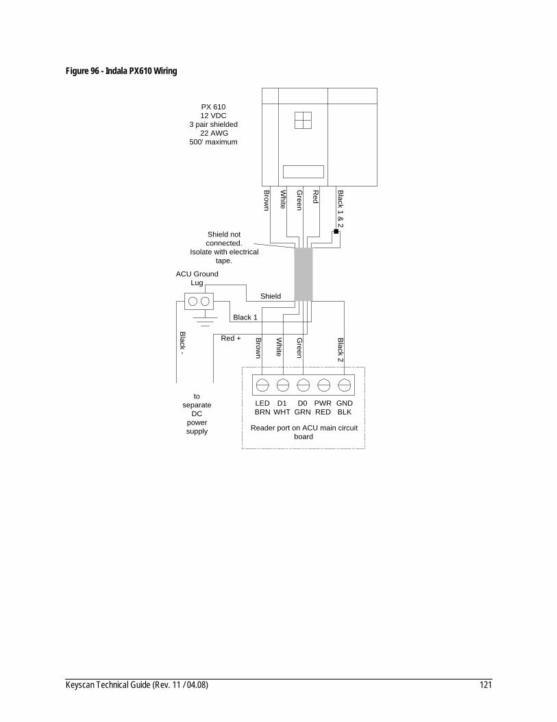
Keyscan Technical Guide (Rev. 11 / 04.08) 121
Figure 96 - Indala PX610 Wiring
Brow
n
White
Green
Red
Black 1 &
2
Shield notconnected.
Isolate with electricaltape.
PX 61012 VDC
3 pair shielded 22 AWG
500' maximum
LEDBRN
D1WHT
D0GRN
PWRRED
GNDBLK
Shield
ACU GroundLug
White
Green
Red + Black 2
Brow
n
Reader port on ACU main circuitboard
Black 1
Black -
toseparate
DCpowersupply
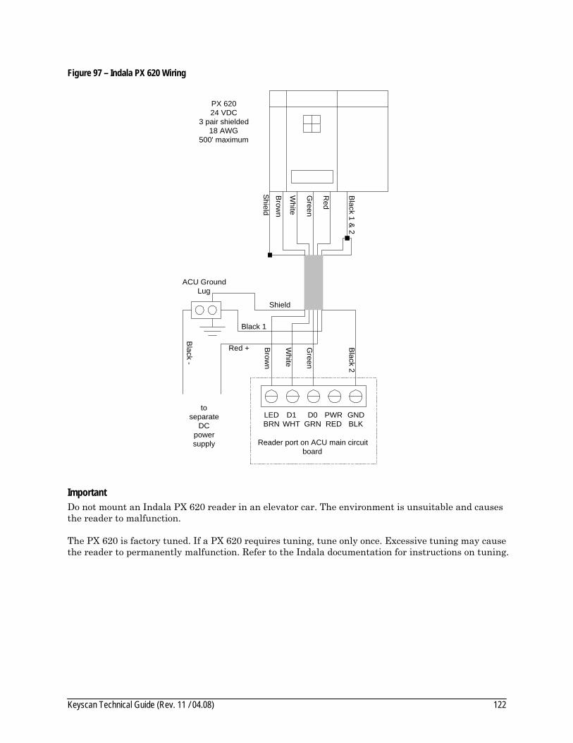
Keyscan Technical Guide (Rev. 11 / 04.08) 122
Figure 97 – Indala PX 620 Wiring
Brow
n
White
Green
Red
Black 1 &
2
Shield
LEDBRN
D1WHT
D0GRN
PWRRED
GNDBLK
Shield
ACU GroundLug
White
Green
Red + Black 2
Brow
n
Reader port on ACU main circuitboard
Black 1
Black -
toseparate
DCpowersupply
PX 62024 VDC
3 pair shielded18 AWG
500' maximum
Important Do not mount an Indala PX 620 reader in an elevator car. The environment is unsuitable and causes the reader to malfunction.
The PX 620 is factory tuned. If a PX 620 requires tuning, tune only once. Excessive tuning may cause the reader to permanently malfunction. Refer to the Indala documentation for instructions on tuning.
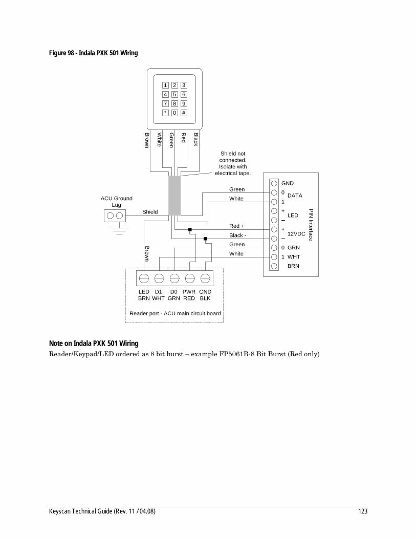
Keyscan Technical Guide (Rev. 11 / 04.08) 123
Figure 98 - Indala PXK 501 Wiring
Brow
n
White
Green
Red
Black
Shield notconnected.Isolate with
electrical tape.
LEDBRN
D1WHT
D0GRN
PWRRED
GNDBLK
Shield
ACU GroundLug
White
Black -
Brow
n
Reader port - ACU main circuit board
Red +
PIN
Interface
GND
1
0
+LED
+12VDC
0
1 WHT
GRN
DATA
BRN
Green
White
Green
1
4
7
*
2
5
8
0
3
6
9
#
Note on Indala PXK 501 Wiring Reader/Keypad/LED ordered as 8 bit burst – example FP5061B-8 Bit Burst (Red only)

Keyscan Technical Guide (Rev. 11 / 04.08) 124
Appendix C – Keyscan WSSKP1 Connections Appendix C reviews typical Keyscan WSSKP-1 keypad connections and keypad/reader combination connections:
• WSSKP-1 – page 125 • WSSKP-1 and reader combination – page 126
Table 16 - Keypad Power Specifications
Reader Power Notes
WSSKP-1 No digital output.
12VDC, 20mA Orange wire not connected.
WSSKP-1 Digital output
12VDC 530mA Orange wire connected.
Installation Notes on Keypads Do not run keypad cables in same conduit with AC power or signal cables.
Keep keypad cables at a minimum distance of 12 inches or 30 centimetres from AC, computer data, telephone data, or electric lock device cables.
Do not install keypads within 3.5 feet or 1.1 metres of computer CRTs.
Do not install readers in areas where broad spectrum EMI noise may be present. Devices such as motors, pumps, generators, and AC switching relays can create EMI noise.
Important Keypads made by other manufacturers may not have the necessary Wiegand interface. Hence these keypads will not operate in dual card and PIN modes; they will only operate in card/reader simulation.

Keyscan Technical Guide (Rev. 11 / 04.08) 125
Figure 99 - WSSKP-1 Keypad Connection
Brow
n
White
Green
Blue
Black
Shield notconnected.Isolate with
electrical tape.
LEDBRN
D1WHT
D0GRN
PWRRED
GNDBLK
Shield
ACU GroundLug
Brow
n
Reader port - ACU main circuit board
White
Green
Blue
Black
3 pair shielded22AWG
500' maximum
1
4
7
*
2
5
8
0
3
6
9
#
Orange to third party
device or tapeback.
Diagram Notes on WSSKP-1 Orange wire in keypad is used for negative digital trigger for a third party device such as a relay or a lock. If using the orange wire, it is triggered from local PIN stored in keypad memory. The keypad memory stores 28 Personal Identification Numbers. If orange wire is not used, tape back. See instructions with WSSKP-1 keypad for connections with third party devices.

Keyscan Technical Guide (Rev. 11 / 04.08) 126
Figure 100 - WSSKP-1 Keypad/Reader Combination Connections
Brow
n
White
Green
Red
Black
Shield notconnected.Isolate with
electrical tape.
LEDBRN
D1WHT
D0GRN
PWRRED
GNDBLK
Shield
ACU GroundLug
Brow
n
Reader port - ACU main circuit board
White
Green
Red
Black
3 pair shielded18AWG
500' maximum
Brow
n
Brow
n
White
White
Green
Blue
Red
Green
Black
Black
Keypad Reader1
4
7
*
2
5
8
0
3
6
9
#
Orange
to third partydevice ortape back
Diagram Notes on WSSKP-1/Reader Combination The above diagram generally applies to a retro-fit where either a reader or keypad is already installed. If a reader/keypad combination is required on a new installation consider such readers as a HID 5355KP or an Indala PXK501.

Keyscan Technical Guide (Rev. 11 / 04.08) 127
Appendix D – RXPROX Receiver / Transmitter Activation Appendix D reviews typical RXPROX transmitter connections and TX2PRX and TX4PRX transmitter button activation.
Table 17 - RXPROX (RF) Receiver Specifications Input Power 12VDC, 35mA
Output Signal 433 MHz (Operating 315 MHz)
Relays 2 Class "C" 30V @ 3A max
Range 30 m (100 ft)
Internal Circuit RF side 9V
RF Output – idle 10mA, 90mW
RF Output – during read 25mA, 225mW
RF Output – peak 185mA, 1.6W
Installation Notes on RXPROX Receiver Do not mount 2 RF receivers within range of each other when using the same transmitter buttons. Assign different transmitter buttons for each RF receiver.
Do not run receiver cable in conduit with AC power or signal wiring. Keep receiver wiring at a minimum of 12" (30cm) from AC wiring.
If receivers exceed the number buttons on the transmitter, do not mount receivers within RF ranges. Minimum distance should be 200 feet.
Reset RXPROX Receiver The following outlines steps to initiate the receiver for transmitter button activation. This resets the RXPROX receiver.
1. Ensure all receiver DIP switches are OFF. 2. Turn DIP switches 5 and 8 ON. 3. Press and hold the RESET button and apply power. 4. Release the RESET button and wait 5 seconds. 5. Turn DIP switch 5 and 8 to OFF. 6. Configure the receiver DIP switches as noted in TX2PRX and TX4PRX Transmitter Button
Activation.

Keyscan Technical Guide (Rev. 11 / 04.08) 128
TX2PRX and TX4PRX Transmitter Button Activation The RXPROX receiver has a set of 8 DIP switches. Switches 1 to 4 assign specific buttons on the TX2PRX and TX4PRX transmitters to activate the RXPROX receiver. All transmitter buttons may be active. Switches 5 to 8 must remain OFF.
The number on the back of the transmitter is the card number that is entered in the cardholder record form in the System V Client software.
TX2PRX Transmitter DIP Switch Assignment • Receiver DIP switch 1 ON – activates
transmitter button 1 • Receiver DIP switch 2 ON – activates
transmitter button 2
TX2 PRX
1 2
TX4PRX Transmitter DIP Switch Assignment • Receiver DIP switch 1 ON – activates
transmitter button 1 • Receiver DIP switch 2 ON – activates
transmitter button 2 • Receiver DIP switch 3 ON – activates
transmitter button 3 • Receiver DIP switch 4 ON – activates
transmitter button 4 TX4 PRX
1 2
3 4

Keyscan Technical Guide (Rev. 11 / 04.08) 129
Figure 101 - RXPROX Receiver Connections
ShieldACU Ground
Lug
ResetPush
ButtonLED
12
34
56
78
O N
Fuse
LEDBRN
D1WHT
D0GRN
PWRRED
GNDBLK
White
Green
Red
Black
Reader port on ACU main circuitboard
Black G
ND
Red 12V
DC
Green Data 0
White Data 1
12VDC
GND
Data 1
Data 0
DIP Switches
Black = position of DIP switch head

Keyscan Technical Guide (Rev. 11 / 04.08) 130
Appendix E – Keyscan COMMex Appendix E reviews typical COMMex connections to extend communication distances from PCs to access control units.
• COMMex overview – page 131 • COMMex connections – page 132
The Keyscan COMMex kit includes two circuit boards. Use one COMMex circuit board as the transmitter and the other as the receiver. Both circuit boards are identical with the exception that one of the circuit boards is mounted in a black case. The circuit board in the black case can be mounted in proximity to the PC or removed from the case if it is to be mounted in a remote enclosure. The maximum distance from the PC is 100 feet.
Table 18 - COMMex Power Specifications
Unit Power Notes
COMMex kit 12VDC, 300mA
Table 19 - COMMex Communication and Cables
Communication Type Maximum Distance Cable
RS232 100 feet Minimum 18 AWG or 22AWG 3 conductor shielded
RS485 4000 feet CAT 5 – 2 twisted pairs
Installation Notes on COMMex From the COMMex circuit board that connects to the PC, insert the female socket end of data cable 40-2322 into a COM port. Be sure to connect the shield to an earth ground.
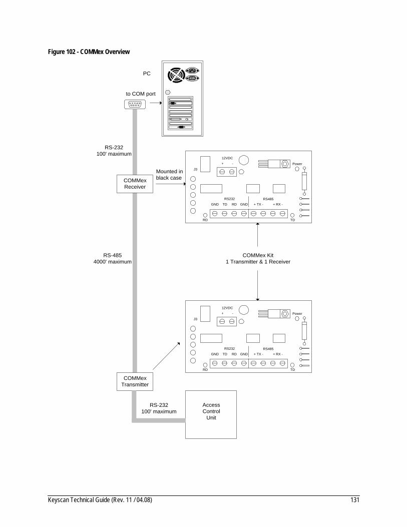
Keyscan Technical Guide (Rev. 11 / 04.08) 131
Figure 102 - COMMex Overview
GNDRS232 RS485
TD RD GND + TX - + RX -
RD TD
12VDC+ - Power
J3
COMMexReceiver
COMMexTransmitter
AccessControl
Unit
PC
to COM port
RS-232100' maximum
RS-232100' maximum
RS-4854000' maximum
COMMex Kit1 Transmitter & 1 Receiver
Mounted inblack case
GNDRS232 RS485
TD RD GND + TX - + RX -
RD TD
12VDC+ - Power
J3

Keyscan Technical Guide (Rev. 11 / 04.08) 132
Figure 103 - COMMex Connections
GNDRS232 RS485TD RD GND + TX - + RX -
RD TD
12VDC+ -
LEDPower
RS
232
Black
Black
Red
Red
Green
Green
J3
Green
Yellow
Black
Red
Red
Black
Yellow
Green
RS
485
Connect to ACU power supply
Connect AC transformer at PC end
GNDRS232 RS485TD RD GND + TX - + RX -
RD TD
12VDC+ -J3
Green
Black
Red
40-2322 femalecable end connects
to PC COM port.Connect shield to earth ground
GND TD RDACU or CPB-10 or CB-485 Communication Terminal
LED LED
+
-
LEDPower
LEDLED
RS
232

Keyscan Technical Guide (Rev. 11 / 04.08) 133
Appendix F – Wiegand Extenders WIEEX and CWIEEX Appendix F reviews general information, installation guidelines, and connection diagrams for Keyscan RS485 Wiegand Extenders (WIEEX) and COAX Wiegand Extenders (CWIEEX). Wiegand extenders are used for doors and readers that exceed the 500 feet maximum distance from the ACU.
Diagrams can be found on the following pages:
• WIEEX/CWIEEX overview – page 135 • WIEEX-connections – page 136 • CWIEXX-connections – page 137 • WIEEX to OCB4 cable connections – page 138
Each type of Wiegand extender includes 1 transmitter and 1 receiver. The following additional components may be required to complete the installation of Wiegand extenders:
• 12VDC 1Amp power supply with battery backup • mounting interface enclosure
Table 20 - WIEEX/CWIEEX Power Requirements
Unit Power Notes
WIEEX Transmitter (Tx) 12VDC, 50mA
WIEEX Receiver (Rx) 12VDC, 50mA
CWIEEX Transmitter (Tx) 12VDC, 50mA
CWIEEX Receiver (Rx) 12VDC, 50mA
OCB-8 12VDC, 230mA Optional – An OCB8 is required when not switching a 12VDC door lock or gate operator. See Figure 107 - WIEEX to OCB-8 Cable Connection on page 138.
Table 21 - WIEEX/CWIEEX Cables and Distances
Unit Connections Maximum Distance Cable
WIEEX Transmitter (Tx) to Reader 500 feet Refer to Table 1 - Cable Requirements - Readers
WIEEX Transmitter (Tx) to Receiver (Rx) 4000 feet CAT 5 - 1 twisted pair (communication) 1 pair 18AWG power if no local independent power supply
WIEEX Receiver (Rx) to ACU 500 feet
CWIEEX Transmitter (Tx) to Reader 500 feet Refer to Table 1 - Cable Requirements – Readers
CWIEEX Transmitter (Tx) to Receiver (Rx)
500 feet RG59U
CWIEEX Receiver (Rx) to ACU 500 feet

Keyscan Technical Guide (Rev. 11 / 04.08) 134
Installation Notes WIEEX (RS485) Existing 22AWG UTP can be used between a WIEEX transmitter and receiver provided it is in good condition without breaks or high impedance splices. Nominal resistance for 22AWG UTP is approximately 18 ohms/1000 feet.
Short J1 on the WIEEX transmitter and receiver.
Connect the WIEEX transmitter (Tx) to the reader, door contact, request to exit device, auxiliary input, and door lock, whichever are applicable.
Connect the WIEEX receiver (Rx) to the appropriate ACU terminals.
Power the transmitter with a 12VDC 1Amp power supply, if a local power supply is required and not sourced from the ACU.
The Door Unlock Output (RA2/OC) is defaulted for 'fail safe'. If 'fail secure' is required, connect a jumper wire from the RB4 terminal to the GND terminal on the transmitter.
The WIEEX transmitter (Tx) can control a lock device or relay to a maximum of 12VDC 500mA.
Installation Notes CWIEEX (COAX) Existing coaxial cable can be used between a CWIEEX transmitter and receiver provided it is in good condition without breaks or high impedance splices.
Connect the WIEEX transmitter (Tx) to the reader, door contact, request to exit device, auxiliary input, and door lock, whichever are applicable.
Connect the WIEEX receiver (Rx) to the appropriate ACU terminals.
The Door Unlock Output (RA2/OC) is defaulted for 'fail safe'. If 'fail secure' is required, connect a jumper wire from the RB4 terminal to the GND terminal on the transmitter.
The CWIEEX transmitter (Tx) can control a lock device or relay to a maximum of 12VDC 500mA.

Keyscan Technical Guide (Rev. 11 / 04.08) 135
Figure 104 - Wiegand Extender Overview
Reader
to Exit Device
Transmitter(WIEEX -Tx)
(CWIEEX - Tx)
Receiver(WIEEX -Rx)
(CWIEEX - Rx)
ACU
to Auxiliary Input
GNDLED +LED -RB7 D1RB6 D0+5VRA2 OCRA1 D1RA0 D0
RB5RB4DCDDTR
RXTXGND
L3
T
R
J1
LED BRND1 WHTD0 GRNData GND
-12V
+
ACor
DC
H1
WIEEX-Tx
(shorted)
WIEEX -Tx
GNDLED +LED -RB7 D1RB6 D0+5VRA2 OCRA1 D1RA0 D0
RB5RB4DCDDTR
RXTXGND
L3
T
R
J1
LED BRND1 WHTD0 GRNData GND
-12V
+
ACor
DC
H1
WIEEX-Rx
(shorted)
WIEEX -Rx
Reader
Exit D
evice
Auxiliary Input
Com
munication
Tx-Rx

Keyscan Technical Guide (Rev. 11 / 04.08) 136
Figure 105 - WIEEX RS485 Transmitter/Receiver Connections
GNDLED +LED -RB7 D1RB6 D0+5VRA2 OCRA1 D1RA0 D0
RB5RB4DCDDTR
RXTXGND
LED BRND1 WHTD0 GRNData GND
-12VDC
+
H1
reader
+12 VDC
COM
Data GND
White Data 1Green Data 0
LED
Red +12VDC
WIEEX-TxTransmitter
Request to Exit Input N.O.
Door Contact Input N.C.
Auxiliary Input N.C.
Door Unlock Output
GNDLED +LED -RB7 D1RB6 D0+5VRA2 OCRA1 D1RA0 D0
RB5RB4DCDDTR
RXTXGND
LED BRND1 WHTD0 GRNData GND
-12VDC
+
H1WIEEX-RxReceiver
+DC Supply (local)-
+ 12 VDC
ACUReader Port
LED
BrnD
1 Wht
D0 G
rn
PW
R R
edG
ND
Black
J1 (shorted)
J1 (shorted)
Trigger for Transmitter R
A2 OC
D1 W
hite
D0 G
reen
GN
D B
lack
+DC Supply
-
+ 12 VDC
CO
M
Maxim
um 4000'
Connect H1 toOCB-8
Door 1 2 1 2 1 2 3 4
ACU Inputs
Exit Auxiliary
Request to E
xit
Door C
ontact
Auxiliary Input
for Com
munications Failure O
utput connect to open Auxiliary Input
Failed Secure Lock
N.O
.C
om
N.C
.
ACULock Relay
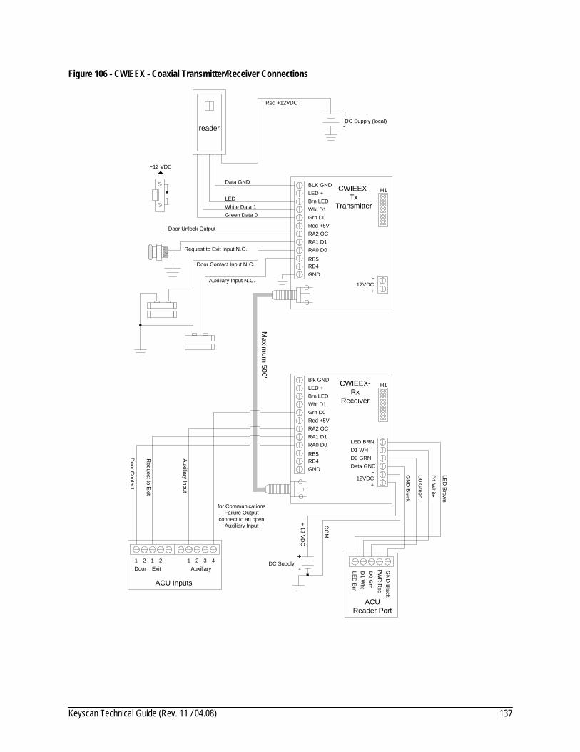
Keyscan Technical Guide (Rev. 11 / 04.08) 137
Figure 106 - CWIEEX - Coaxial Transmitter/Receiver Connections
BLK GNDLED +Brn LEDWht D1Grn D0Red +5VRA2 OCRA1 D1RA0 D0
RB5RB4GND
-12VDC
+
H1
reader
+12 VDC
Data GND
White Data 1Green Data 0
LED
Red +12VDC
CWIEEX-Tx
Transmitter
Request to Exit Input N.O.
Door Contact Input N.C.
Auxiliary Input N.C.
Door Unlock Output
Blk GNDLED +Brn LED Wht D1Grn D0Red +5VRA2 OCRA1 D1RA0 D0
RB5RB4GND
LED BRND1 WHTD0 GRNData GND
-12VDC
+
H1CWIEEX-Rx
Receiver
+DC Supply (local)-
ACUReader Port
LED
BrnD
1 Wht
D0 G
rn
PW
R R
edG
ND
Black
LED B
rown
D1 W
hite
D0 G
reen
GN
D B
lack
+DC Supply
-
+ 12 VDC
CO
M
Maxim
um 500'
Door 1 2 1 2 1 2 3 4
ACU Inputs
Exit Auxiliary
Request to E
xit
Door C
ontact
Auxiliary Input
for CommunicationsFailure Output
connect to an openAuxiliary Input
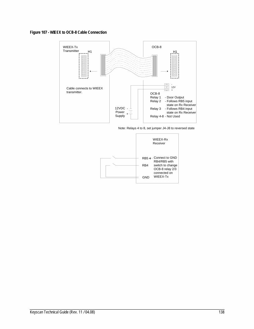
Keyscan Technical Guide (Rev. 11 / 04.08) 138
Figure 107 - WIEEX to OCB-8 Cable Connection
H1WIEEX-TxTransmitter H1
OCB-8
Cable connects to WIEEX transmitter. OCB-8
Relay 1 Relay 2 Relay 3 Relay 4-8
-12V +
+
-12VDCPowerSupply
WIEEX-RxReceiver
RB5
RB4
Connect to GND RB4/RB5 with switch to change OCB-8 relay 2/3 connected on WIEEX-TxGND
- Door Output- Follows RB5 input state on Rx Receiver - Follows RB4 input state on Rx Receiver- Not Used
Note: Relays 4 to 8, set jumper J4-J8 to reversed state

Keyscan Technical Guide (Rev. 11 / 04.08) 139
Appendix G – Handicap Accessibility Relay Option The handicap accessibility relay is designed to connect with an accessibility operator that mechanically opens and closes a door. Presenting a card with the Handicap Accessibility designation at a valid door pulses a handicap (HC) output relay. The HC output relay pulses the accessibility operator and the system monitors the door contact based on the Handicap Door Held Open Time set in the System V software. To use the Handicap Relay option on CA 4300 and CA 8300 circuit boards, an additional OCB-8 is required.
Table 22 - OCB8 Power Specifications
Unit Power Notes
OCB-8 12VDC, 230mA
Handicap Relays Ensure that the HC Output Relay matches the Door Output as indicated below.
Table 23 - Handicap Relay/ Door Assignment
Main Circuit Board/Output Control Board
Door # /HC Relay # Ribbon Cable Connection to Main Circuit Board
CA 230/OCB-8 Door 1/HC Relay 5 Door 2/HC Relay 6 Relay 7 and 8 reserved for Pre-alert.
Connect ribbon from OCB-8 to Control 1 (right terminal) on CA 230
CA 4300/OCB-8 (optional) Door 1/HC Relay 1 Door 2/HC Relay 2 Door 3/HC Relay 3 Door 4/HC Relay 4 Relays 5 to 8 not used.
Connect ribbon on OCB-8 to Control 4 (right terminal) on CA 4300.
CA 8300/OCB-8 (optional) Door 1/HC Relay 1 Door 2/HC Relay 2 Door 3/HC Relay 3 Door 4/HC Relay 4 Door 5/HC Relay 5 Door 6/HC Relay 6 Door 7/HC Relay 7 Door 8/HC Relay 8
Connect ribbon on OCB-8 to Control 4 (right terminal) on CA 8300.
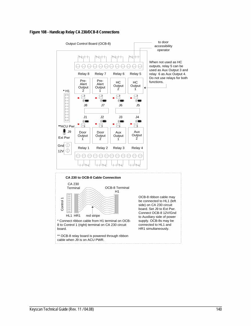
Keyscan Technical Guide (Rev. 11 / 04.08) 140
Figure 108 - Handicap Relay CA 230/OCB-8 Connections
DoorOutput
1
DoorOutput
2
AuxOutput
1
AuxOutput
2
HCOutput
1
J1 J2 J3 J4
J5J6J7J8
Output Control Board (OCB-8)
Gnd
J9
Ext Pwr
12V
**ACU Pwr
* H1
Relay 1 Relay 2 Relay 3 Relay 4
Relay 5Relay 6Relay 7Relay 8
HCOutput
2
Pre-Alert
Output1
Pre-Alert
Output2
to dooraccessibility
operator
When not used as HCoutputs, relay 5 can beused as Aux Output 3 andrelay 6 as Aux Output 4.Do not use relays for bothfunctions.
* Connect ribbon cable from H1 terminal on OCB-8 to Control 1 (right) terminal on CA 230 circuitboard.
** OCB-8 relay board is powered through ribboncable when J9 is on ACU PWR.
CA 230 to OCB-8 Cable Connection
red stripe
H1
CA 230Terminal OCB-8 Terminal
Con
trol 1
HR1HL1
OCB-8 ribbon cable maybe connected to HL1 (leftside) on CA 230 circuitboard. Set J9 to Ext Pwr.Connect OCB-8 12V/Gndto Auxiliary side of powersupply. OCB-8s may beconnected to HL1 andHR1 simultaneously.

Keyscan Technical Guide (Rev. 11 / 04.08) 141
Figure 109 - Handicap Relay CA 4300/OCB-8 Connections
HCOutput
1
HCOutput
2
HCOutput
4
HCOutput
3
J1 J2 J3 J4
J5J6J7J8
Output Control Board (OCB-8)
Gnd
J9
Ext Pwr
12V
**ACU Pwr
* H1
Relay 1 Relay 2 Relay 3 Relay 4
Relay 5Relay 6Relay 7Relay 8
to dooraccessibilityoperator
Relaynot
used
Relaynot
used
Relaynot
used
Relaynot
used
* Connect ribbon cable from H1 terminalon OCB-8 to Control 4 - HR4 terminal(right side) on CA 4300 circuit board.
** OCB-8 relay board is powered throughribbon cable when J9 is on ACU PWR.
CA 4300 to OCB-8 Cable Connection
red stripe
H1CA 4300Terminal
OCB-8 Terminal
Con
trol 4
HR4HL4
OCB-8 ribbon cablemay be connected toHL4 (left side) on CA4300 circuit board. SetJ9 to Ext Pwr.Connect OCB-8 12V/Gnd to Auxiliary sideof power supply.OCB-8s may beconnected to HL4 andHR4 simultaneously.
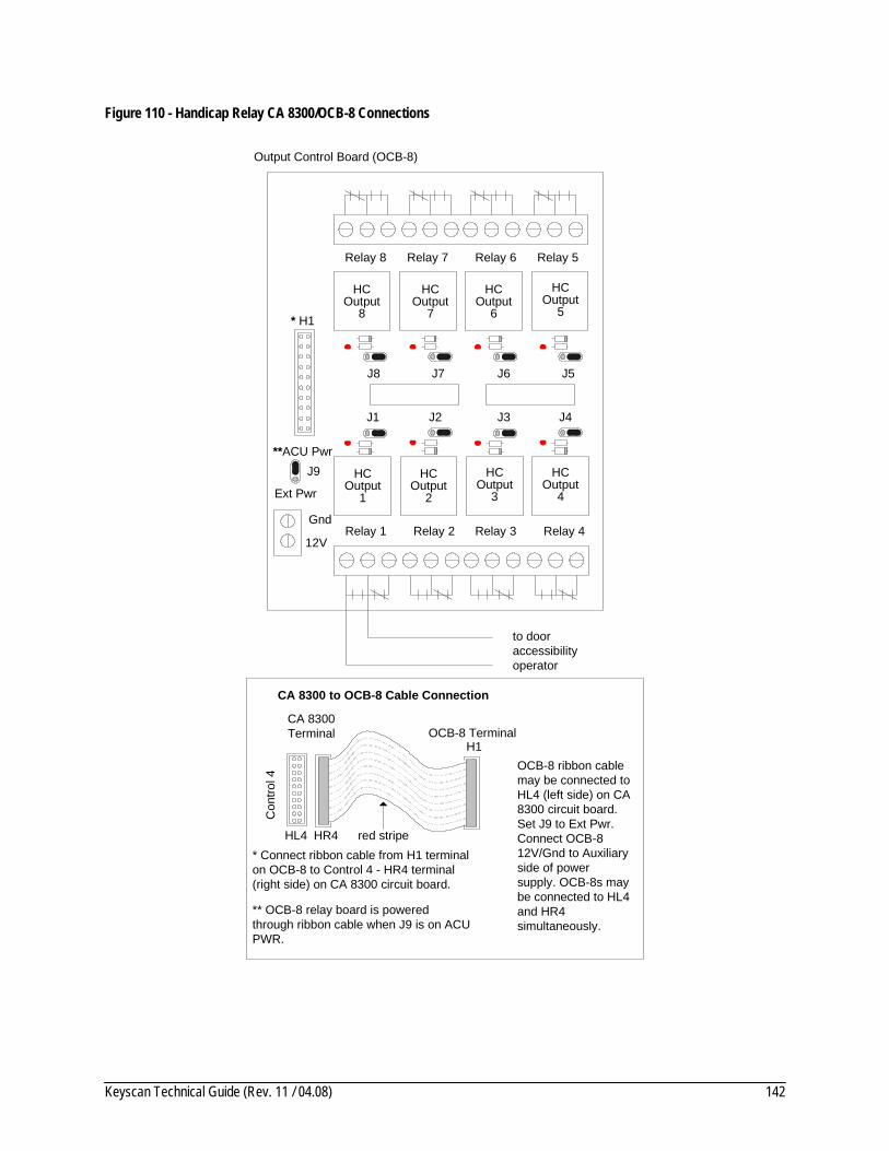
Keyscan Technical Guide (Rev. 11 / 04.08) 142
Figure 110 - Handicap Relay CA 8300/OCB-8 Connections
HC Output
1
HC Output
2
HC Output
4
HCOutput
3
J1 J2 J3 J4
J5J6J7J8
Output Control Board (OCB-8)
Gnd
J9
Ext Pwr
12V
**ACU Pwr
* H1
Relay 1 Relay 2 Relay 3 Relay 4
Relay 5Relay 6Relay 7Relay 8
to dooraccessibilityoperator
HC Output
5
HC Output
6
HC Output
7
HC Output
8
* Connect ribbon cable from H1 terminal on OCB-8 to Control 4 - HR4 terminal (right side) on CA 8300 circuit board.
** OCB-8 relay board is powered through ribbon cable when J9 is on ACU PWR.
CA 8300 to OCB-8 Cable Connection
red stripe
H1
CA 8300Terminal OCB-8 Terminal
Con
trol 4
HR4HL4
OCB-8 ribbon cable may be connected to HL4 (left side) on CA 8300 circuit board. Set J9 to Ext Pwr. Connect OCB-8 12V/Gnd to Auxiliary side of power supply. OCB-8s may be connected to HL4 and HR4 simultaneously.
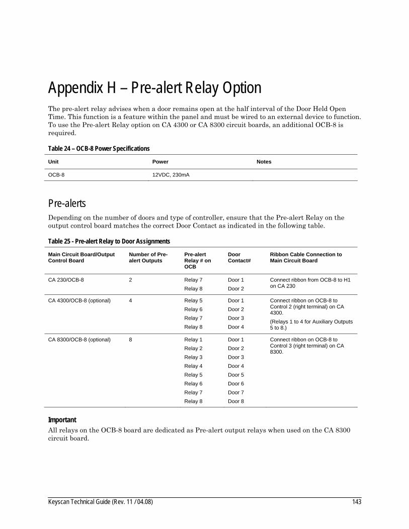
Keyscan Technical Guide (Rev. 11 / 04.08) 143
Appendix H – Pre-alert Relay Option The pre-alert relay advises when a door remains open at the half interval of the Door Held Open Time. This function is a feature within the panel and must be wired to an external device to function. To use the Pre-alert Relay option on CA 4300 or CA 8300 circuit boards, an additional OCB-8 is required.
Table 24 – OCB-8 Power Specifications
Unit Power Notes
OCB-8 12VDC, 230mA
Pre-alerts Depending on the number of doors and type of controller, ensure that the Pre-alert Relay on the output control board matches the correct Door Contact as indicated in the following table.
Table 25 - Pre-alert Relay to Door Assignments
Main Circuit Board/Output Control Board
Number of Pre-alert Outputs
Pre-alert Relay # on OCB
Door Contact#
Ribbon Cable Connection to Main Circuit Board
CA 230/OCB-8
2 Relay 7 Relay 8
Door 1 Door 2
Connect ribbon from OCB-8 to H1 on CA 230
CA 4300/OCB-8 (optional) 4 Relay 5 Relay 6 Relay 7 Relay 8
Door 1 Door 2 Door 3 Door 4
Connect ribbon on OCB-8 to Control 2 (right terminal) on CA 4300. (Relays 1 to 4 for Auxiliary Outputs 5 to 8.)
CA 8300/OCB-8 (optional) 8 Relay 1 Relay 2 Relay 3 Relay 4 Relay 5 Relay 6 Relay 7 Relay 8
Door 1 Door 2 Door 3 Door 4 Door 5 Door 6 Door 7 Door 8
Connect ribbon on OCB-8 to Control 3 (right terminal) on CA 8300.
Important All relays on the OCB-8 board are dedicated as Pre-alert output relays when used on the CA 8300 circuit board.
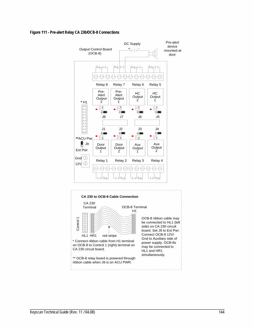
Keyscan Technical Guide (Rev. 11 / 04.08) 144
Figure 111 - Pre-alert Relay CA 230/OCB-8 Connections
DoorOutput
1
DoorOutput
2
AuxOutput
1
AuxOutput
2
HCOutput
1
J1 J2 J3 J4
J5J6J7J8
Output Control Board(OCB-8)
Gnd
J9
Ext Pwr
12V
**ACU Pwr
* H1
Relay 1 Relay 2 Relay 3 Relay 4
Relay 5Relay 6Relay 7Relay 8
HCOutput
2
Pre-Alert
Output1
Pre-Alert
Output2
Pre-alertdevice
mounted atdoor
DC Supply+ -
* Connect ribbon cable from H1 terminalon OCB-8 to Control 1 (right) terminal onCA 230 circuit board.
** OCB-8 relay board is powered throughribbon cable when J9 is on ACU PWR.
CA 230 to OCB-8 Cable Connection
red stripe
H1
CA 230Terminal OCB-8 Terminal
Con
trol 1
HR1HL1
OCB-8 ribbon cable maybe connected to HL1 (leftside) on CA 230 circuitboard. Set J9 to Ext Pwr.Connect OCB-8 12V/Gnd to Auxiliary side ofpower supply. OCB-8smay be connected toHL1 and HR1simultaneously.
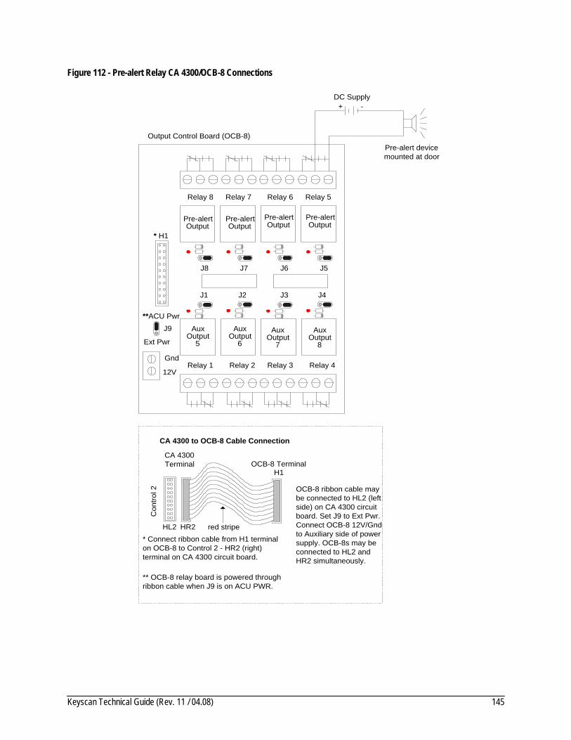
Keyscan Technical Guide (Rev. 11 / 04.08) 145
Figure 112 - Pre-alert Relay CA 4300/OCB-8 Connections
J1 J2 J3 J4
J5J6J7J8
Output Control Board (OCB-8)
Gnd
J9
Ext Pwr
12V
**ACU Pwr
* H1
Relay 1 Relay 2 Relay 3 Relay 4
Relay 5Relay 6Relay 7Relay 8
Pre-alert devicemounted at door
DC Supply
Pre-alertOutput
Pre-alertOutput
Pre-alertOutput
AuxOutput
5
-+
AuxOutput
6
AuxOutput
7
AuxOutput
8
Pre-alertOutput
* Connect ribbon cable from H1 terminalon OCB-8 to Control 2 - HR2 (right)terminal on CA 4300 circuit board.
** OCB-8 relay board is powered throughribbon cable when J9 is on ACU PWR.
CA 4300 to OCB-8 Cable Connection
red stripe
H1
CA 4300Terminal OCB-8 Terminal
Con
trol 2
HR2HL2
OCB-8 ribbon cable maybe connected to HL2 (leftside) on CA 4300 circuitboard. Set J9 to Ext Pwr.Connect OCB-8 12V/Gndto Auxiliary side of powersupply. OCB-8s may beconnected to HL2 andHR2 simultaneously.

Keyscan Technical Guide (Rev. 11 / 04.08) 146
Figure 113 - Pre-alert Relay CA 8300/OCB-8 Connections
Pre-alertOutput
J1 J2 J3 J4
J5J6J7J8
Output Control Board (OCB-8)
Gnd
J9
Ext Pwr
12V
**ACU Pwr
* H1
Relay 1 Relay 2 Relay 3 Relay 4
Relay 5Relay 6Relay 7Relay 8
Pre-alert devicemounted at door
DC Supply
* Connect ribbon cable from H1 terminal onOCB-8 to Control 3 - HR3 terminal (right side)on CA 8300.
Pre-alertOutput
Pre-alertOutput
Pre-alertOutput
Pre-alertOutput
Pre-alertOutput
Pre-alertOutput
Pre-alertOutput
-+
** OCB-8 relay board is powered throughribbon cable when J9 is on ACU PWR.
CA 8300 to OCB-8 Cable Connection
red stripe
H1
CA 8300Terminal OCB-8 Terminal
Con
trol 3
HR3HL3
OCB-8 ribbon cablemay be connected toHL3 (left side) on CA8300 circuit board. SetJ9 to Ext Pwr. ConnectOCB-8 12V/Gnd toAuxiliary side of powersupply. OCB-8s may beconnected to HL3 andHR3 simultaneously.
Keyscan Technical Guide (Rev. 11 / 04.08) 147
Appendix I – MISCOMM2 Communication between Buildings on a CPB-10 Loop For ACU communication between two buildings on a CPB-10 loop, we recommend using one of the following devices:dial-up modem, fiber optic modem, short haul modem or an asynchronous line driver with optical isolation.
When using a fiber optic modem, short haul modem, or an asynchronous line driver with optical isolation, a Miscellaneous Communication Board (MISCOMM2) is required.
The MISCOMM2 consists of two boards that are modified CPB-10s. One board connects to the ACU via a ribbon cable and the second connects via a terminal block to the fiber optic modem, short haul modem, or asynchronous line driver with optical isolation. The following table and diagrams illustrate voltages and installation connections for a single ACU and multiple ACUs.
• MISCOMM2 inter-building communication to a single ACU – page 148 • MISCOMM2 connections – to a single ACU – page 149 • MISCOMM2 inter-building communication to multiple ACUs – page 150 • MISCOMM2 connections to multiple ACUs – page 151
Important We do not recommend using two CPB-10s for inter-building communication as the potential for a ground loop surge exists which may damage equipment.
Ground Loops A ground loop is a current across a cable created by a difference in potential between two grounded points, as may exist with two buildings connected by a long run of EIA/TIA-562, RS485 or other data cables. When two devices are connected with potential ground differences, voltage flows from high to low through the data cable, even the ground wire. If the voltage potential is large enough, the equipment is unable to handle the excess voltage and as a result the communication ports are damaged. Even small ground loop voltages cause transmission errors with data signals riding on top of the ground loop current.
Table 26 - MISCOMM2 Voltages
Board Contact Voltage Notes
MISCOMM2 7 (GND) to 1 (+) 12VDC
7 (GND) to 2 (-) 8 to (-) 12VDC line driver generated
7 (GND) to 3 (-) 8 to (-) 12VDC pin 3 generated
7 (GND) to 5 (-) 10VDC

Keyscan Technical Guide (Rev. 11 / 04.08) 148
Figure 114 - MISCOMM2 – Inter Building Communication to a single ACU
via Line Driveror
Fiber Modem
MainCircuitBoard
ACU 1
Building 2
RS232 in fromBuilding 1
RS
232 out
MainCircuitBoard
RibbonCable
TerminalBlock
ACU 1
Building 1
MISCOMM2RS232
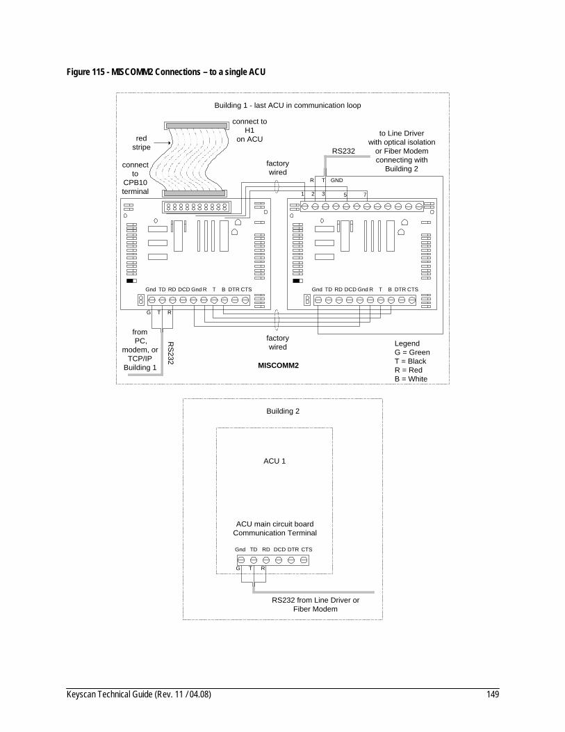
Keyscan Technical Guide (Rev. 11 / 04.08) 149
Figure 115 - MISCOMM2 Connections – to a single ACU
TGnd TD RD DCD Gnd R B DTR CTS TGnd TD RD DCD Gnd R B DTR CTS
from PC,
modem, orTCP/IP
Building 1
factorywired
2 3
GND
1 5 7
RS232
MISCOMM2
connect toH1
on ACU
Building 1 - last ACU in communication loop
redstripe
connectto
CPB10terminal
Gnd TD RD DCD DTR CTS
Building 2
ACU main circuit boardCommunication Terminal
factorywired
ACU 1
to Line Driverwith optical isolation
or Fiber Modemconnecting with
Building 2
RS232 from Line Driver orFiber Modem
TR
T RG
RS
232
G T R
LegendG = GreenT = BlackR = RedB = White

Keyscan Technical Guide (Rev. 11 / 04.08) 150
Figure 116 - MISCOMM2 Inter Building Communication to Multiple ACUs
via Line Driveror
Fiber Modem
MainCircuitBoard
CPB-10
MainCircuitBoard
CPB-10
ACU 1ACU 2
Building 2
RS232 in fromBuilding 1
RS
232 out
EIA/TIA 562
MainCircuitBoard
CPB-10
MainCircuitBoard
RibbonCable
TerminalBlock
ACU 1 ACU 2
Building 1
MISCOMM2RS232 EIA/TIA 562
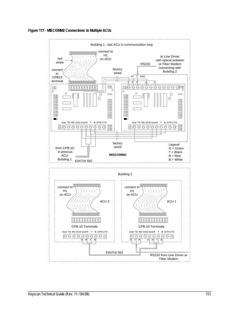
Keyscan Technical Guide (Rev. 11 / 04.08) 151
Figure 117 - MISCOMM2 Connections to Multiple ACUs
TGnd TD RD DCD Gnd R B DTR CTS TGnd TD RD DCD Gnd R B DTR CTS
EIA/TIA 562
from CPB-10 in prevous
ACUBuilding 1
factorywired
2 3
GND
1 5 7
RS232
MISCOMM2
connect toH1
on ACU
Building 1 - last ACU in communication loop
redstripe
connectto
CPB10terminal
TGnd TD RD DCD Gnd R B DTR CTSTGnd TD RD DCD Gnd R B DTR CTS
Building 2
connect toH1
on ACU
connect toH1
on ACU
CPB-10 TerminalsCPB-10 Terminals
factorywired
ACU 1ACU 2
to Line Driverwith optical isolation
or Fiber Modemconnecting with
Building 2
RS232 from Line Driver orFiber Modem
TR
T RG
EIA/TIA 562
G TR BG TR B
LegendG = GreenT = BlackR = RedB = White

Keyscan Technical Guide (Rev. 11 / 04.08) 152
Appendix J – Telephone Entry Systems Keyscan access control systems interface with two types of telephone entry systems:
• Phone Bill – requires a dedicated telephone line • No Phone Bill – requires relay control equipment
Supported Telephone Entry Systems Keyscan systems interface with the following major brands of telephone entry systems, which have a communication port and transmit visitor activity information:
• Enterphone 2000, Electra, Axess, and Crusader • Select Engineered Systems (SES), TEC, and CAT • Sentex Infinity
Keyscan Telephone Interface Kits Keyscan offers the following 3 interface kits:
• VIS100 ENT interface kit used with Enterphone 2000, Axess, and Crusader (Axess and Crusader require RS-485 to RS-232 converter from Viscount). See page 153 for connections.
• VIS100 SES interface kit used with Enterphone Electra or SES, TEC and CAT series entrance panels. These panels require an OPTKSERIAL communications interface board from the manufacturer. See page 154 for connections.
• VIS100 STX interface kit used with Sentex Infinity series entrance panel. See page 155 for connections.
Test Mode Terminal RB7/D1 on the interface is used for testing Wiegand output wiring and board operation. To test, connect a wire from RB7/D1 to ground and apply power to the interface board. The interface board outputs card number 12345, batch 000 in test mode. To exit test mode, remove the wire from RB7/D1.
Entering Access Codes in Client Software Each suite or tenant must be given a record that is created in the Cardholder form from the Keyscan Client software as follows:
• First Name field – suite number or suite name • Last Name field – last name of tenant • Card Number – entry code or relay number • Batch field – 255
Refer to the Client on-line help for setting access levels, time zones etc.
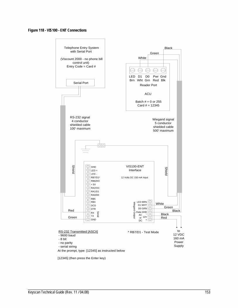
Keyscan Technical Guide (Rev. 11 / 04.08) 153
Figure 118 - VIS100 - ENT Connections
VIS100-ENTInterface
12 Volts DC 150 mA Input
LEDBrn
D1Wht
D0Grn
PwrRed
GndBlk
Reader Port
ACU
Batch # = 0 or 255Card # = 12345
Telephone Entry Systemwith Serial Port
(Viscount 2000 - no phone billcontrol unit)
Entry Code = Card #
Serial Port
RS-232 Transmitted [ASCII]- 9600 baud- 8 bit- no parity- serial string
RS-232 signal4 conductor
shielded cable100' maximum
Wiegand signal5 conductor
shielded cable500' maximum
Shield
Red
Green
GreenWhite
Black
Shield
BlackRed
to12 VDC160 mAPowerSupply
GreenWhite
Black
GNDLED +LED -RB7/D1*RB6/DO+ 5VRA2/OCRA1/D1
RB5RB4DCDDTR
RXTXGND
RA0/D0
Wiegand O
utput
LED BRND1 WHTD0 GRN
Data GND-
12V+
ACor
DC
* RB7/D1 - Test Mode
Serial
At the prompt, type: [12345] as instructed below
[12345] (then press the Enter key)

Keyscan Technical Guide (Rev. 11 / 04.08) 154
Figure 119 - VIS100 SES Connections
* RB7\ D1: Test Mode
VIS100-SES(formally ELK-100)
Interface
12 Volts DC 150 mA Input
LEDBrn
D1Wht
D0Grn
PwrRed
GndBlk
Reader Port
ACU
Batch # = 0 or 255Card # = 123
Telephone Entry Systemwith Serial Port
Select Engineered SystemsTEC or CAT Entry Systems and
Enterphone Electra 2 TEC2require OPTKSERIALEntry Code = Card #
Serial Port
RS232 Transmitted [ASCII]- 9600 baud- 8 bit- no parity- serial stringAt the prompt, type: CODE 123 OPEN as instructed below
CODE (insert a space) 123 (insert 2 spaces) OPEN (insert a space and then press theEnter key)
Shield
Red
Green
GreenWhite
Black
Shield
BlackRed
to12 VDC160 mAPowerSupply
GreenWhite
Black
RS-232 signal4 conductor
shielded cable100' maximum
Wiegand signal5 conductor
shielded cable500' maximum
GNDLED +LED -RB7/D1*RB6/DO+ 5VRA2/OCRA1/D1
RB5RB4DCDDTR
RXTXGND
RA0/D0
Wiegand O
utput
LED BRND1 WHTD0 GRN
Data GND-
12V+
ACor
DC
Serial

Keyscan Technical Guide (Rev. 11 / 04.08) 155
Figure 120 - VIS100 STX Connections
* RB7\ D1: Test Mode
VIS100-STXInterface
12 Volts DC 150 mA Input
LEDBrn
D1Wht
D0Grn
PwrRed
GndBlk
Reader Port
ACU
Batch # = 0 or 255Card # = 12345
Telephone Entry Systemwith Serial Port
Sentex Infinity Entry CodeSingle Line LCD
Large LCDComport B on boardShort RTS + CTS
Entry Code = Card #
Serial Port
RS232 Transmitted [ASCII]- 4800 baud- 8 bit- no parity- serial stringAt the prompt, type: [ PHONE ENTRY 12345 GRANTED] as instructed below
[ (insert a space) PHONE (insert a space) ENTRY (insert 2 spaces) 12345(insert 2 spaces) GRANTED] (press the Enter key)
Shield
Red
Green
GreenWhite
Black
Shield
BlackRed
to12 VDC160 mAPowerSupply
GreenWhite
Black
RS-232 signal4 conductor
shielded cable100' maximum
Wiegand signal5 conductor
shielded cable500' maximum
GNDLED +LED -RB7/D1*RB6/DO+ 5VRA2/OCRA1/D1
RB5RB4DCDDTR
RXTXGND
RA0/D0
Wiegand O
utput
LED BRND1 WHTD0 GRN
Data GND-
12V+
ACor
DC
Serial
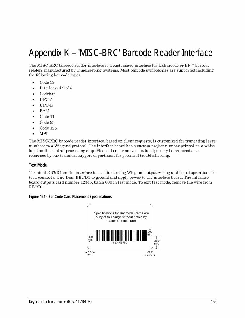
Keyscan Technical Guide (Rev. 11 / 04.08) 156
Appendix K – 'MISC-BRC' Barcode Reader Interface The MISC-BRC barcode reader interface is a customized interface for EZBarcode or BR-7 barcode readers manufactured by TimeKeeping Systems. Most barcode symbologies are supported including the following bar code types:
• Code 39 • Interleaved 2 of 5 • Codebar • UPC-A • UPC-E • EAN • Code 11 • Code 93 • Code 128 • MSI
The MISC-BRC barcode reader interface, based on client requests, is customized for truncating large numbers to a Wiegand protocol. The interface board has a custom project number printed on a white label on the central processing chip. Please do not remove this label; it may be required as a reference by our technical support department for potential troubleshooting.
Test Mode Terminal RB7/D1 on the interface is used for testing Wiegand output wiring and board operation. To test, connect a wire from RB7/D1 to ground and apply power to the interface board. The interface board outputs card number 12345, batch 000 in test mode. To exit test mode, remove the wire from RB7/D1.
Figure 121 - Bar Code Card Placement Specifications
.100"min.
.450"min.
.500"min.
.500"min.
.100"min.
Specifications for Bar Code Cards aresubject to change without notice by
reader manufacturer

Keyscan Technical Guide (Rev. 11 / 04.08) 157
Figure 122 - MISC-BRC Barcode Reader Interface Connections
Barcode Reader
Black VIS100-WZ/485Interface R3
Power requirements12 VDC 150 mA
GNDLED +LED -RB7/D1*RB6/DO+ 5VRA2/OCRA1/D1
RB5RB4DCDDTR
RXTXGND
RA0/D0
Wiegand O
utput
LED BRND1 WHTD0 GRN
Data GND-
12V+
ACorDC
Serial
Orange
Brown
Red
GreenTTL
ASCIIOutput
1200 baud
Isolate shieldand
tape back
Yellow
Blue
Purple
notconnected
Project number
RS-232 Signal5 conductor shielded cable
100' maximum
Wiegand Signal4 conductor cable
500' maximum
+
*RB7/D1 terminal used for test mode
-
12VDCPowerSupply
Shield
Isolateshieldand
tape back
LEDBrn
D1Wht
D0Grn
PwrRed
GndBlk
Reader Port
Brown
Green
White
Black
ACU
Shield

Keyscan Technical Guide (Rev. 11 / 04.08) 158
CA 230 Quick Reference Figure 123 - CA 230 Circuit Board
TP2 +12V
Aux RdrPwr In
12VDC
PowerFail
DetectACU
PowerIN
PWR 5V
LithiumBattery
B1
TP3 -10V
+
-
EARTHGND
12VDC+
-
TP1 5V
SYS JMPJ16
1
CB 485 Connection
J17
ClearMemory
J1
J6
SysReset
Reader TypeJ3
L1 L0
TP4 Reset 5V Normal
Reader 1Reader 2
Reader PortLEDBrn
D1Wht
D0Grn
PwrRed
GndBlk
TX
RX
Con
trol 1
Con
trol 2
Con
trol 3
Con
trol 4
Con
trol 5
HR1HL1C
omm
on R
etur
n
HL2
HL3
HL4
HL5
1 Door Contacts N.C.
2 1 2 Request to Exit N.O.
1 2 3 4 5 6 Supervised Auxiliary/Alarm Inputs N.C.
7 8 Communication
GNDTD RDDCD DTRCTS
Left Right
TD RD
Reader Prom
System Prom
Clock Chip
Communication 2
IOCB3216
2 3 4 5 6 7 8
Binary
5 4 3 2 1
TP5 5V
GND
Test Points
ACUCurrent Consumption
140 mA MAX
CA R11
J7ReaderReset
J18Address | Ext Jmp
F11
U43
U4A B C D E
123456
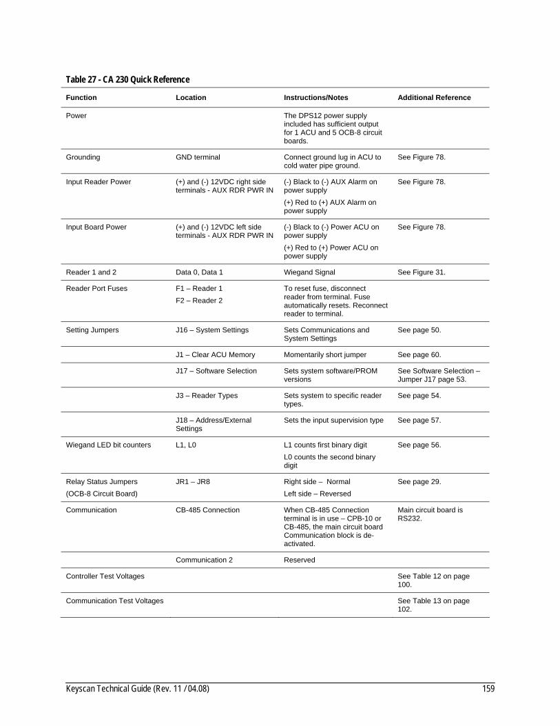
Keyscan Technical Guide (Rev. 11 / 04.08) 159
Table 27 - CA 230 Quick Reference
Function Location Instructions/Notes Additional Reference
Power The DPS12 power supply included has sufficient output for 1 ACU and 5 OCB-8 circuit boards.
Grounding GND terminal Connect ground lug in ACU to cold water pipe ground.
See Figure 78.
Input Reader Power (+) and (-) 12VDC right side terminals - AUX RDR PWR IN
(-) Black to (-) AUX Alarm on power supply (+) Red to (+) AUX Alarm on power supply
See Figure 78.
Input Board Power (+) and (-) 12VDC left side terminals - AUX RDR PWR IN
(-) Black to (-) Power ACU on power supply (+) Red to (+) Power ACU on power supply
See Figure 78.
Reader 1 and 2 Data 0, Data 1 Wiegand Signal See Figure 31.
Reader Port Fuses F1 – Reader 1 F2 – Reader 2
To reset fuse, disconnect reader from terminal. Fuse automatically resets. Reconnect reader to terminal.
Setting Jumpers J16 – System Settings Sets Communications and System Settings
See page 50.
J1 – Clear ACU Memory Momentarily short jumper See page 60.
J17 – Software Selection Sets system software/PROM versions
See Software Selection – Jumper J17 page 53.
J3 – Reader Types Sets system to specific reader types.
See page 54.
J18 – Address/External Settings
Sets the input supervision type See page 57.
Wiegand LED bit counters L1, L0 L1 counts first binary digit L0 counts the second binary digit
See page 56.
Relay Status Jumpers (OCB-8 Circuit Board)
JR1 – JR8 Right side – Normal Left side – Reversed
See page 29.
Communication CB-485 Connection When CB-485 Connection terminal is in use – CPB-10 or CB-485, the main circuit board Communication block is de-activated.
Main circuit board is RS232.
Communication 2 Reserved
Controller Test Voltages See Table 12 on page 100.
Communication Test Voltages See Table 13 on page 102.
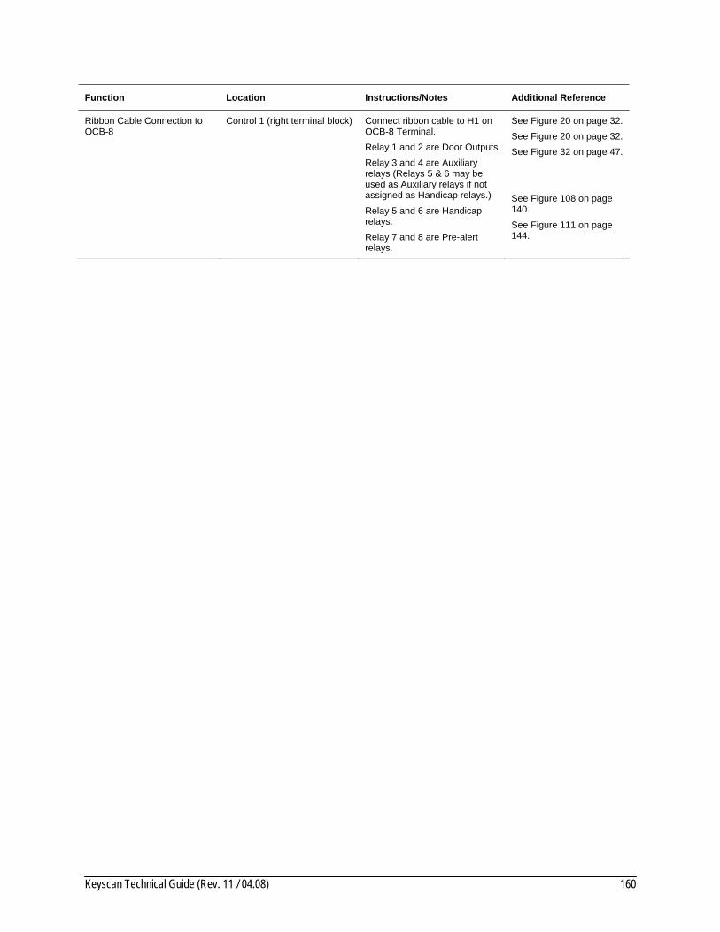
Keyscan Technical Guide (Rev. 11 / 04.08) 160
Function Location Instructions/Notes Additional Reference
Ribbon Cable Connection to OCB-8
Control 1 (right terminal block) Connect ribbon cable to H1 on OCB-8 Terminal. Relay 1 and 2 are Door Outputs Relay 3 and 4 are Auxiliary relays (Relays 5 & 6 may be used as Auxiliary relays if not assigned as Handicap relays.) Relay 5 and 6 are Handicap relays. Relay 7 and 8 are Pre-alert relays.
See Figure 20 on page 32. See Figure 20 on page 32. See Figure 32 on page 47. See Figure 108 on page 140. See Figure 111 on page 144.

Keyscan Technical Guide (Rev. 11 / 04.08) 161
This page is intentionally blank.
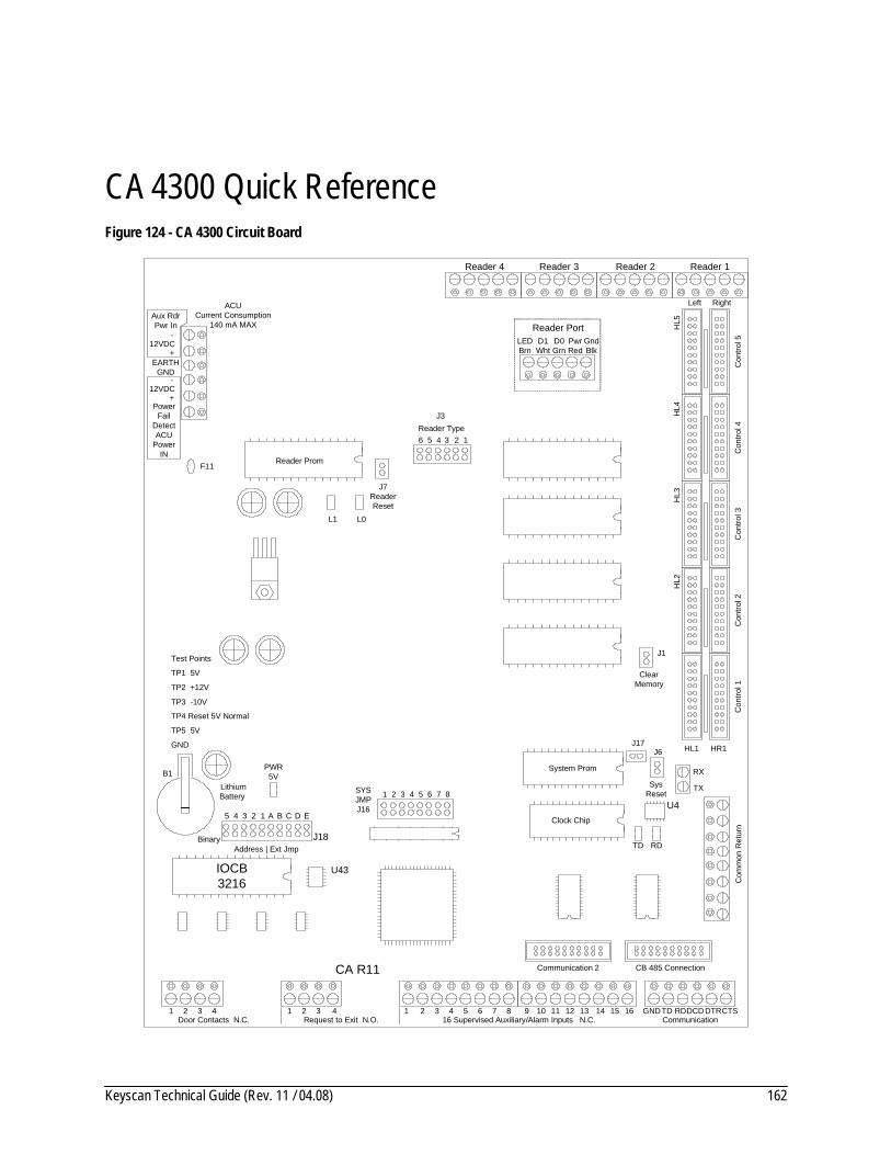
Keyscan Technical Guide (Rev. 11 / 04.08) 162
CA 4300 Quick Reference Figure 124 - CA 4300 Circuit Board
TP2 +12V
Aux RdrPwr In
12VDC
PowerFail
DetectACU
PowerIN
PWR 5V
LithiumBattery
B1
TP3 -10V
+
-
EARTHGND
12VDC+
-
TP1 5V
SYS JMPJ16
1
CB 485 Connection
J17
ClearMemory
J1
J6
SysReset
Reader TypeJ3
L1 L0
TP4 Reset 5V Normal
Reader 1Reader 2Reader 3
Reader PortLEDBrn
D1Wht
D0Grn
PwrRed
GndBlk
TX
RX
Con
trol 1
Con
trol 2
Con
trol 3
Con
trol 4
Con
trol 5
HR1HL1C
omm
on R
etur
n
HL2
HL3
HL4
HL5
1 Door Contacts N.C.
2 3 4 1 2 3 4 Request to Exit N.O.
1 2 3 4 5 6 16 Supervised Auxiliary/Alarm Inputs N.C.
7 8 9 10 11 12 13 14 15 16 Communication
GNDTD RDDCD DTRCTS
Reader 4
Left Right
TD RD
Reader Prom
System Prom
Clock Chip
Communication 2
IOCB3216
2 3 4 5 6 7 8
TP5 5V
GND
Test Points
ACUCurrent Consumption
140 mA MAX
CA R11
J7ReaderReset
F11
U43
U4
Binary
5 4 3 2 1
J18Address | Ext Jmp
A B C D E
123456

Keyscan Technical Guide (Rev. 11 / 04.08) 163
Table 28 - CA 4300 Quick Reference
Function Location Instructions/Notes Additional Reference
Power The DPS12 power supply included has sufficient output for 1 ACU and 5 OCB-8 circuit boards.
Grounding GND terminal – AUX RDR PWR IN
Connect ground lug in ACU to cold water pipe ground
See Figure 78.
Input Reader Power (+) and (-) 12VDC upper terminals - AUX RDR PWR IN
(-) Black to (-) AUX Alarm on power supply (+) Red to (+) AUX Alarm on power supply
See Figure 78.
Input Board Power (+) and (-) 12VDC lower terminals - AUX RDR PWR IN
(-) Black to (-) Power ACU on power supply (+) Red to (+) Power ACU on power supply
See Figure 78.
Readers 1 to 4 Data 0, Data 1 Wiegand Signal See Figure 31.
Reader Port Fuses F1 – Reader 1 F2 – Reader 2 F3 – Reader 3 F4 – Reader 4
To reset fuse, disconnect reader from terminal. Fuse automatically resets. Reconnect reader to terminal.
Setting Jumpers J16 – System Settings Sets Communications and System Settings
See page 50.
J1 – Clear ACU Memory Momentarily short jumper See page 60.
J17 – Software Selection Sets system software/PROM versions
See page 53.
J3 – Reader Types Sets system to specific reader types.
See page 54.
J18 – Address/External Settings
Sets the input supervision type See page 57.
Wiegand LED bit counters L1, L0 L1 counts first binary digit L0 counts the second binary digit
See page 56.
Relay Status Jumpers (OCB -8 Circuit Board)
JR1 – JR8 Right side – Normal Left side – Reversed
See page 29.
Communication CB-485 Connection When CB-485 Connection terminal is in use – CPB-10 or CB-485, the main circuit board Communication block is de-activated.
Main circuit is RS232.
Communication 2 Reserved
Controller Test Voltages See Table 12 on page 100.
Communication Test Voltages See Table 13 on page 102.

Keyscan Technical Guide (Rev. 11 / 04.08) 164
Function Location Instructions/Notes Additional Reference
Ribbon Cable Connection to OCB-8
1st OCB 8 H1 on OCB-8 to Control 1 (right terminal) CA 4300 (red stripe on bottom)
See Figure 21 on page 33.
2nd OCB 8 (optional) H1 on OCB 8 to Control 2 (right terminal) CA 4300 Use Control 2 for Pre-Alert relays (red stripe on bottom)
See Figure 112 on page 145.
Control 3 not used
3rd OCB 8 (optional) H1 on OCB 8 to Control 4 (right terminal) CA 4300 Use Control 4 for Handicap Accessibility relays. (red stripe on bottom)
See Figure 109 on page 141.
Control 5 not used

Keyscan Technical Guide (Rev. 11 / 04.08) 165
This page is intentionally blank.
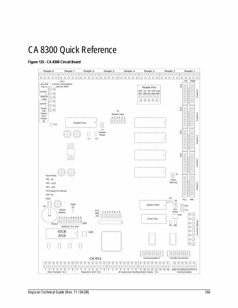
Keyscan Technical Guide (Rev. 11 / 04.08) 166
CA 8300 Quick Reference Figure 125 - CA 8300 Circuit Board
TP2 +12V
Aux RdrPwr In
12VDC
PowerFail
DetectACU
PowerIN
PWR 5V
LithiumBattery
B1
TP3 -10V
+
-
EARTHGND
12VDC+
-
TP1 5V
SYS JMPJ16
1
CB 485 Connection
J17
ClearMemory
J1
J6
SysReset
Reader TypeJ3
L1 L0
TP4 Reset 5V Normal
Reader 1Reader 2Reader 3
Reader PortLEDBrn
D1Wht
D0Grn
PwrRed
GndBlk
TX
RX
Con
trol 1
Con
trol 2
Con
trol 3
Con
trol 4
Con
trol 5
HR1HL1C
omm
on R
etur
n
HL2
HL3
HL4
HL5
1 Door Contacts N.C.
2 3 4 1 2 3 4 Request to Exit N.O.
1 2 3 4 5 6 16 Supervised Auxiliary/Alarm Inputs N.C.
7 8 9 10 11 12 13 14 15 16 Communication
GNDTD RDDCD DTRCTS5 6 7 85 6 7 8
Reader 4Reader 5Reader 6Reader 7Reader 8
Left Right
TD RD
Reader Prom
System Prom
Clock Chip
Communication 2
IOCB3216
2 3 4 5 6 7 8
TP5 5V
GND
Test Points
ACUCurrent Consumption
140 mA MAX
CA R11
J7ReaderReset
F11
U43
U4
Binary
5 4 3 2 1
J18Address | Ext Jmp
A B C D E
123456

Keyscan Technical Guide (Rev. 11 / 04.08) 167
Table 29 - CA 8300 Quick Reference
Function Location Instructions/Notes Additional Reference
Power The DPS12 power supply included has sufficient output for 1 ACU and 5 OCB-8 circuit boards.
Grounding GND terminal – AUX RDR PWR IN
Connect ground lug in ACU to cold water pipe ground
See Figure 78.
Input Reader Power (+) and (-) 12VDC upper terminals - AUX RDR PWR IN
(-) Black to (-) AUX Alarm on power supply (+) Red to (+) AUX Alarm on power supply
See Figure 78.
Input Board Power (+) and (-) 12VDC lower terminals - AUX RDR PWR IN
(-) Black to (-) Power ACU on power supply (+) Red to (+) Power ACU on power supply
See Figure 78.
Readers 1 to 8 Data 0, Data 1 Wiegand Signal Main circuit board is RS232.
Reader Port Fuses F1 – Reader 1 F2 – Reader 2 F3 – Reader 3 F4 – Reader 4 F5 – Reader 5 F6 – Reader 6 F7 – Reader 7 F8 – Reader 8
To reset fuse, disconnect reader from terminal. Fuse automatically resets. Reconnect reader to terminal.
Setting Jumpers J16 – System Settings Sets Communications and System Settings
See page 50.
J1 – Clear ACU Memory Momentarily short jumper See page 60.
J17 – Software Selection Sets system software/PROM versions
See page 53.
J3 – Reader Types Sets system to specific reader types.
See page 54.
J18 – Address/External Settings
Sets the input supervision type See page 57.
Wiegand LED bit counters L1, L0 L1 counts first binary digit L0 counts the second binary digit
See page 56.
Relay Status Jumpers (OCB -8 Circuit Board)
JR1 – JR8 Right side – Normal Left side – Reversed
See page 29.
Communication CB-485 Connection When CB-485 Connection terminal is in use – CPB-10 or CB-485, the main circuit board Communication block is de-activated.
Communication 2 Reserved
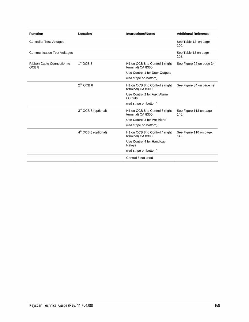
Keyscan Technical Guide (Rev. 11 / 04.08) 168
Function Location Instructions/Notes Additional Reference
Controller Test Voltages See Table 12 on page 100.
Communication Test Voltages See Table 13 on page 102.
Ribbon Cable Connection to OCB 8
1st OCB 8 H1 on OCB 8 to Control 1 (right terminal) CA 8300 Use Control 1 for Door Outputs (red stripe on bottom)
See Figure 22 on page 34.
2nd OCB 8 H1 on OCB 8 to Control 2 (right terminal) CA 8300 Use Control 2 for Aux. Alarm Outputs. (red stripe on bottom)
See Figure 34 on page 49.
3rd OCB 8 (optional) H1 on OCB 8 to Control 3 (right terminal) CA 8300 Use Control 3 for Pre-Alerts (red stripe on bottom)
See Figure 113 on page 146.
4th OCB 8 (optional) H1 on OCB 8 to Control 4 (right terminal) CA 8300 Use Control 4 for Handicap Relays (red stripe on bottom)
See Figure 110 on page 142.
Control 5 not used

Keyscan Technical Guide (Rev. 11 / 04.08) 169
This page is intentionally blank.

Keyscan Technical Guide (Rev. 11 / 04.08) 170
EC 1300 Quick Reference Figure 126 - EC 1300 Circuit Board
TP2 +12V
Aux RdrPwr In
12VDC
PowerFail
DetectACU
PowerIN
PWR 5V
LithiumBattery
B1
TP3 -10V
+
-
EARTHGND
12VDC+
-
TP1 5V
SYS JMPJ16
1
CB 485 Connection
J17
ClearMemory
J1
J6
SysReset
Reader TypeJ3
L1 L0
TP4 Reset 5V Normal
Reader 1Reader 2
Reader PortLEDBrn
D1Wht
D0Grn
PwrRed
GndBlk
TX
RX
Con
trol 1
Con
trol 2
Con
trol 3
Con
trol 4
Con
trol 5
HR1C
omm
on R
etur
n
1 Door Contacts N.C.
2 3 4 1 2 3 4 Request to Exit N.O.
1 2 3 4 5 6 16 Supervised Auxiliary/Alarm Inputs N.C.
7 8 9 10 11 12 13 14 15 16 Communication
GNDTD RDDCD DTRCTS5 6 7 85 6 7 8
Right
TD RD
Reader Prom
System Prom
Clock Chip
Communication 2
IOCB3216
2 3 4 5 6 7 8
TP5 5V
GND
Test Points
ACUCurrent Consumption
140 mA MAX
CA R11
J7ReaderReset
F11
U43
U4
(not used)
Floor Inputs 1 - 16 Floor Inputs 17 - 32
Binary
5 4 3 2 1
J18Address | Ext Jmp
A B C D E
123456

Keyscan Technical Guide (Rev. 11 / 04.08) 171
Table 30 - EC 1300 Quick Reference
Function Location Instructions/Notes Additional Reference
Power The DPS12 power supply included has sufficient output for 1 ACU and 5 OCB-8 circuit boards.
Grounding GND terminal – AUX RDR PWR IN
Connect ground lug in ACU to cold water pipe ground
See Figure 78.
Input Reader Power (+) and (-) 12VDC upper terminals - AUX RDR PWR IN
(-) Black to (-) AUX Alarm on power supply (+) Red to (+) AUX Alarm on power supply
See Figure 78.
Input Board Power (+) and (-) 12VDC lower terminals - AUX RDR PWR IN
(-) Black to (-) Power ACU on power supply (+) Red to (+) Power ACU on power supply
See Figure 78.
Reader 1 Data 0, Data 1 Wiegand Signal See Figure 31.
Reader Port Fuses F1 – Reader 1 To reset fuse, disconnect reader from terminal. Fuse automatically resets. Reconnect reader to terminal.
Setting Jumpers J16 – System Settings Sets Communications and System Settings
See page 50.
J1 – Clear ACU Memory Momentarily short jumper See page 60.
J17 – Software Selection Sets system software/PROM versions
See page 53.
J3 – Reader Types Sets system to specific reader types.
See page 54.
Wiegand LED bit counters L1, L0 L1 counts first binary digit L0 counts the second binary digit
See page 56.
Relay Status Jumpers (OCB -8 Circuit Board)
JR1 – JR8 Right side – Normal Left side – Reversed
See page 29.
Communication CB-485 Connection When CB-485 Connection terminal is in use – CPB-10 or CB-485, the main circuit board Communication block is de-activated.
Communication 2 Reserved
Controller Test Voltages See Table 12 on page 100.
Communication Test Voltages See Table 13 page 102
Ribbon Cable Connection to OCB 8
1st OCB 8 Floors 1 to 8
H1 on OCB 8 to Control 1 (right terminal) EC 1300 (red stripe on bottom)
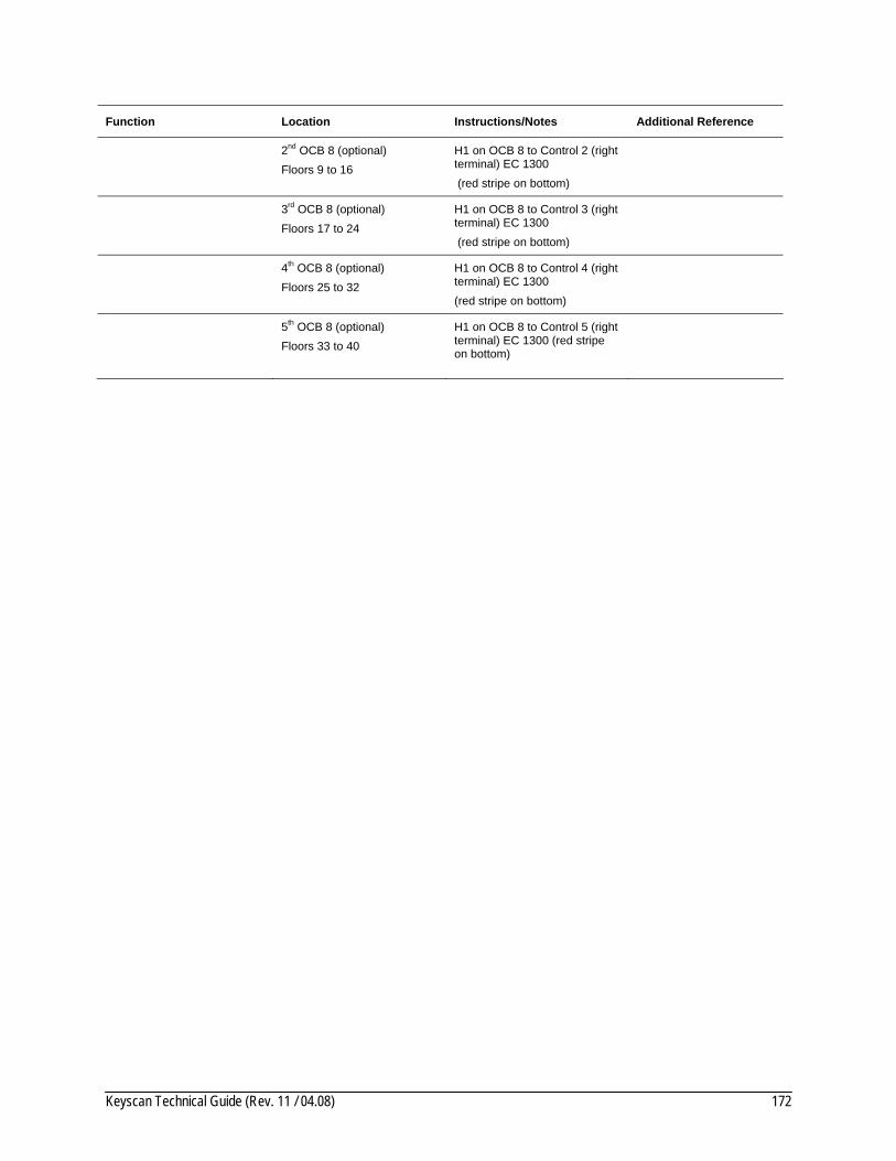
Keyscan Technical Guide (Rev. 11 / 04.08) 172
Function Location Instructions/Notes Additional Reference
2nd OCB 8 (optional) Floors 9 to 16
H1 on OCB 8 to Control 2 (right terminal) EC 1300 (red stripe on bottom)
3rd OCB 8 (optional) Floors 17 to 24
H1 on OCB 8 to Control 3 (right terminal) EC 1300 (red stripe on bottom)
4th OCB 8 (optional) Floors 25 to 32
H1 on OCB 8 to Control 4 (right terminal) EC 1300 (red stripe on bottom)
5th OCB 8 (optional) Floors 33 to 40
H1 on OCB 8 to Control 5 (right terminal) EC 1300 (red stripe on bottom)

Keyscan Technical Guide (Rev. 11 / 04.08) 173
This page is intentionally blank.
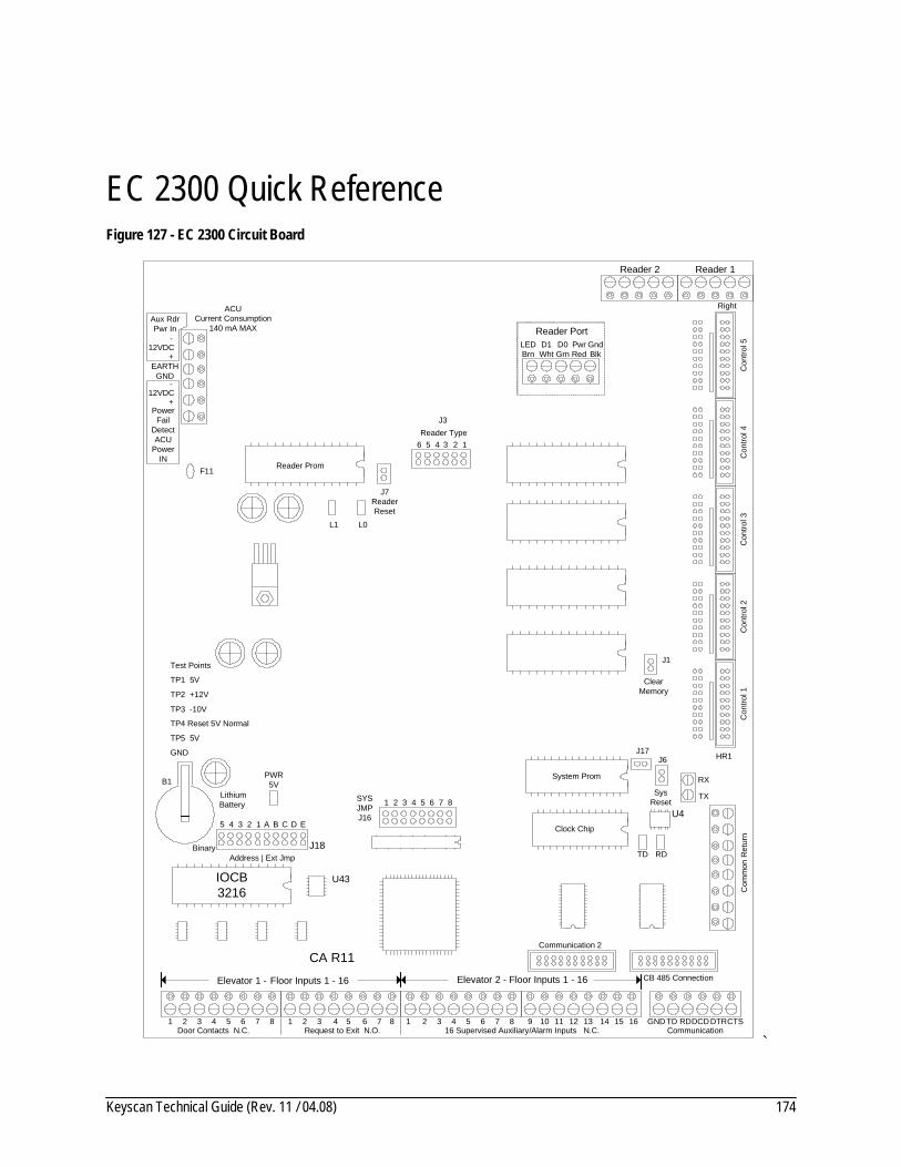
Keyscan Technical Guide (Rev. 11 / 04.08) 174
EC 2300 Quick Reference Figure 127 - EC 2300 Circuit Board
TP2 +12V
Aux RdrPwr In
12VDC
PowerFail
DetectACU
PowerIN
PWR 5V
LithiumBattery
B1
TP3 -10V
+
-
EARTHGND
12VDC+
-
TP1 5V
SYS JMPJ16
1
CB 485 Connection
J17
ClearMemory
J1
J6
SysReset
Reader TypeJ3
L1 L0
TP4 Reset 5V Normal
Reader 1Reader 2
Reader PortLEDBrn
D1Wht
D0Grn
PwrRed
GndBlk
TX
RX
Con
trol 1
Con
trol 2
Con
trol 3
Con
trol 4
Con
trol 5
HR1C
omm
on R
etur
n
1 Door Contacts N.C.
2 3 4 1 2 3 4 Request to Exit N.O.
1 2 3 4 5 6 16 Supervised Auxiliary/Alarm Inputs N.C.
7 8 9 10 11 12 13 14 15 16 Communication
GNDTD RDDCD DTRCTS5 6 7 85 6 7 8
Right
TD RD
Reader Prom
System Prom
Clock Chip
Communication 2
IOCB3216
2 3 4 5 6 7 8
TP5 5V
GND
Test Points
ACUCurrent Consumption
140 mA MAX
CA R11
J7ReaderReset
F11
U43
U4
Elevator 1 - Floor Inputs 1 - 16 Elevator 2 - Floor Inputs 1 - 16
Binary
5 4 3 2 1
J18Address | Ext Jmp
A B C D E
123456
`
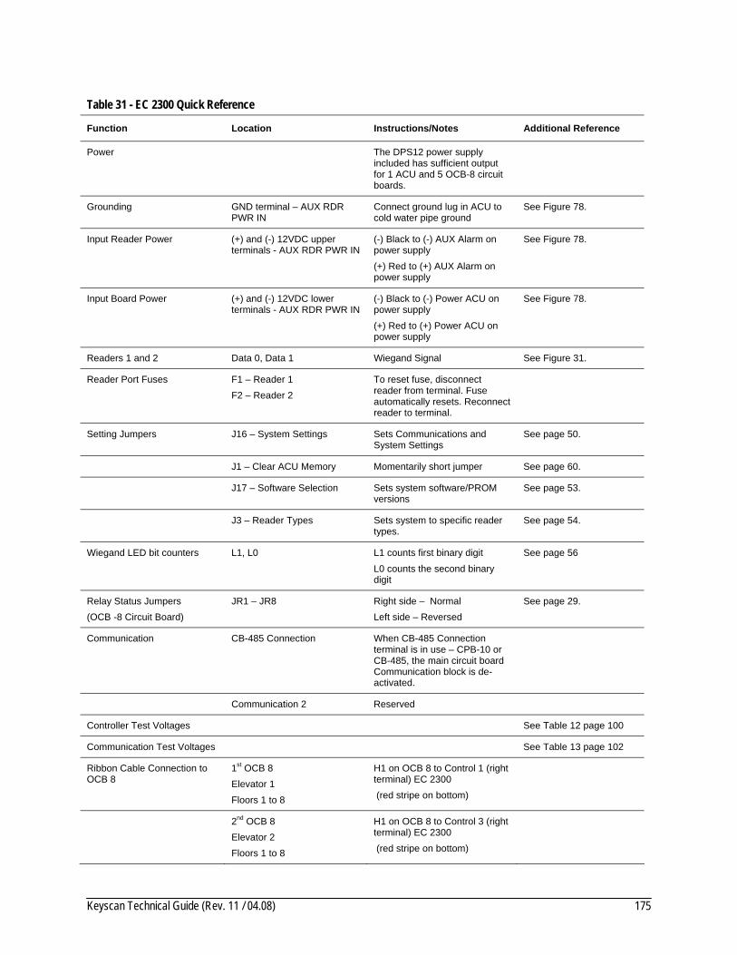
Keyscan Technical Guide (Rev. 11 / 04.08) 175
Table 31 - EC 2300 Quick Reference
Function Location Instructions/Notes Additional Reference
Power The DPS12 power supply included has sufficient output for 1 ACU and 5 OCB-8 circuit boards.
Grounding GND terminal – AUX RDR PWR IN
Connect ground lug in ACU to cold water pipe ground
See Figure 78.
Input Reader Power (+) and (-) 12VDC upper terminals - AUX RDR PWR IN
(-) Black to (-) AUX Alarm on power supply (+) Red to (+) AUX Alarm on power supply
See Figure 78.
Input Board Power (+) and (-) 12VDC lower terminals - AUX RDR PWR IN
(-) Black to (-) Power ACU on power supply (+) Red to (+) Power ACU on power supply
See Figure 78.
Readers 1 and 2 Data 0, Data 1 Wiegand Signal See Figure 31.
Reader Port Fuses F1 – Reader 1 F2 – Reader 2
To reset fuse, disconnect reader from terminal. Fuse automatically resets. Reconnect reader to terminal.
Setting Jumpers J16 – System Settings Sets Communications and System Settings
See page 50.
J1 – Clear ACU Memory Momentarily short jumper See page 60.
J17 – Software Selection Sets system software/PROM versions
See page 53.
J3 – Reader Types Sets system to specific reader types.
See page 54.
Wiegand LED bit counters L1, L0 L1 counts first binary digit L0 counts the second binary digit
See page 56
Relay Status Jumpers (OCB -8 Circuit Board)
JR1 – JR8 Right side – Normal Left side – Reversed
See page 29.
Communication CB-485 Connection When CB-485 Connection terminal is in use – CPB-10 or CB-485, the main circuit board Communication block is de-activated.
Communication 2 Reserved
Controller Test Voltages See Table 12 page 100
Communication Test Voltages See Table 13 page 102
Ribbon Cable Connection to OCB 8
1st OCB 8 Elevator 1 Floors 1 to 8
H1 on OCB 8 to Control 1 (right terminal) EC 2300 (red stripe on bottom)
2nd OCB 8 Elevator 2 Floors 1 to 8
H1 on OCB 8 to Control 3 (right terminal) EC 2300 (red stripe on bottom)

Keyscan Technical Guide (Rev. 11 / 04.08) 176
Function Location Instructions/Notes Additional Reference
3rd OCB 8 (optional) Elevator 1 Floors 9 to 16
H1 on OCB 8 to Control 2 (right terminal) EC 2300 (red stripe on bottom)
4th OCB 8 (optional) Elevator 2 Floors 9 to 16
H1 on OCB 8 to Control 4 (right terminal) EC 2300 (red stripe on bottom)

Keyscan Technical Guide (Rev. 11 / 04.08) 177
Relay States Table 32 – List of Relay States
Device Relay Jumper Status Possible TZ Status
LED State N.C. Relay State
N.O. Relay State
Door Relay Normal Unlocked ON
Door Relay Normal Locked OFF
Door Relay Reversed Unlocked ON
Door Relay Reversed Locked OFF
Aux Output Relay Normal Door Held Open Alarm
-
Aux Output Relay Normal Alarm Tripped
-
Aux Output Relay Reversed Door Held Open Alarm
-
Aux Output Relay Reversed Alarm Tripped
-
Aux Output Relay Normal
OFF
Aux Output Relay Normal
ON
Aux Output Relay Reversed
OFF
Aux Output Relay Reversed
ON
Pre-alert Relay Normal Activated -
Pre-alert Relay Normal Normal -
Pre-alert Relay Reversed Activated -
Pre-alert Relay Reversed Normal -
Accessibility Relay Normal Activated -
Accessibility Relay Normal Normal -
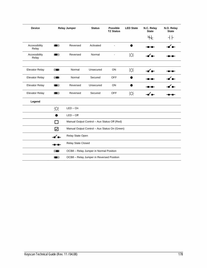
Keyscan Technical Guide (Rev. 11 / 04.08) 178
Device Relay Jumper Status Possible TZ Status
LED State N.C. Relay State
N.O. Relay State
Accessibility Relay Reversed Activated -
Accessibility Relay Reversed Normal -
Elevator Relay Normal Unsecured ON
Elevator Relay Normal Secured OFF
Elevator Relay Reversed Unsecured ON
Elevator Relay Reversed Secured OFF
Legend
LED – On
LED – Off
Manual Output Control – Aux Status Off (Red)
Manual Output Control – Aux Status On (Green)
Relay State Open
Relay State Closed
OCB8 – Relay Jumper in Normal Position
OCB8 – Relay Jumper in Reversed Position

Keyscan Technical Guide (Rev. 11 / 04.08) 179
Warranty Limited Warranty Keyscan warrants that all Keyscan manufactured products shall be free of defects in materials and workmanship under normal use for a period of two years from the date of purchase. In fulfillment of any breach of such warranty, Keyscan shall, at its option, repair or replace defective equipment upon return to its facilities. This warranty applies only to defective parts or workmanship. This warranty does not apply to damage that occurred during shipping or handling, or damage due to causes beyond the control of Keyscan such as lightning, excessive voltage, mechanical shock, water damage, or damage arising out of abuse, alteration or improper application of the equipment.
This warranty does not extend to products distributed by Keyscan that are manufactured by 3rd parties. The original equipment manufacturer's warranty shall apply.
The foregoing warranty shall apply only to the original buyer and is and shall be in lieu of any and all other warranties, whether expressed or implied and of all other obligations or liabilities on the part of Keyscan. This warranty contains the entire warranty. Keyscan neither assumes, nor authorizes any other person purporting to act on its behalf to modify or to change this warranty, nor to assume for it any other warranty or liability concerning this product.
In no event shall Keyscan be liable for any direct, indirect, or consequential damages, loss of anticipated profits, loss of time or any other losses incurred by the buyer in connection with the purchase, installation, or operation or failure of this product.
WARNING – Keyscan recommends that the entire system be completely tested on a regular basis. However, despite frequent testing and due to, but not limited to, criminal tampering or electrical disruption, it is possible for this product to fail to perform as expected.
Seller’s Right of Possession In addition to all remedies Keyscan may possess, Keyscan shall have the right at any time for credit reasons or because of buyer’s defaults, to withhold shipments in whole or in part, to recall goods in transit, retake same and repossess all goods which may be stored, without the necessity of taking any other action.
Buyer consents that all merchandise so recalled, retaken, or repossessed shall become the absolute property of Keyscan provided that buyer is promptly notified of such action and is given full credit therefore.
Product Installation and Operation Buyer assumes all responsibility for the proper selection, installation, operation, maintenance and adherence to any and all federal, state/provincial and municipal building and fire codes of the merchandise purchased from Keyscan. Keyscan SHALL NOT BE RESPONSIBLE FOR ANY CONSEQUENTIAL, CONTINGENT, SPECIAL OR INCIDENTAL DAMAGES whatsoever, except as specifically set forth in the LIMITED WARRANTY.

Keyscan Technical Guide (Rev. 11 / 04.08) 180
Index A
approved standards, 9 auxiliary output relays, 46
B barcode
reader interface, 156 symbologies, 156
battery duration times, 18
baud rates, 50 button activation
TX2PRX/TX4PRX, 127
C cable requirements, 11 COAX Wiegand Extenders (CWIEEX), 133 COMMex connections, 130 communication LEDs, 96 current requirements
calculate, 29
D door
contacts, 27 door strikes
diodes, 29
E elevator/floor assignments, 40 enclosure
dimensions, 16 exit buttons, 27
F fail-safe, 30 fail-secure, 30
G ground loop, 147 grounding, 12
H handicap accessibility relay, 139 HID reader connections, 105
I Indala proximity reader connections, 119
J jumpers
clear ACU memory, 60 reader formats J3, 54 software selection J17, 53 system settings J16, 50
K Keyscan K-PROX, 105 Keyscan warranty, 179 Keyscan WSSKP-1 keypad connections, 124
L lock hardware, 26
M MISCOMM2
inter-building communication, 147 modem communication, 61 mounting
access control unit, 16 circuit boards, 19 door hardware, 25 power supply, 18 readers, 28
P PIRs, 27 power, 10 power supply
specifications, 98 pre-alert relay, 143
R Relay States, 177 relay status

Keyscan Technical Guide (Rev. 11 / 04.08) 181
jumpers, 29 RXPROX transmitter connections, 127
S stand offs, 17
T telephone entry systems, 152 terminate
input wiring, 35 tools, 10 transformers, 18
V voltage test points
ACU/CPB-10 communication terminal, 102 main circuit boards, 100
W Wiegand bit counter LEDs, 56 Wiegand Extenders (WIEEX), 133