copyright © 2002 delmar thomson learning chapter 13 understanding relay instructions and the...
DESCRIPTION
Copyright © 2002 Delmar Thomson Learning Objectives (cont’d.) Explain why PLC ladder logic for motor starter interface has an additional contact in comparison to a conventional schematic. Hook up a start-stop station to a PLC input module. Hook up and develop a PLC program to correctly control a motor starter.TRANSCRIPT

Copyright © 2002 Delmar Thomson Learning
Chapter 13
Understanding Relay Instructions
and the Programmable Controller Input
Modules

Copyright © 2002 Delmar Thomson Learning
ObjectivesExplain proper programming of normal
closed and normally open PLC input signals.
Describe hardware relay operation and its correlation to proper PLC interface and programming.
Convert a conventional start-stop schematic to a PLC ladder rung diagram.

Copyright © 2002 Delmar Thomson Learning
Objectives (cont’d.)Explain why PLC ladder logic for
motor starter interface has an additional contact in comparison to a conventional schematic.
Hook up a start-stop station to a PLC input module.
Hook up and develop a PLC program to correctly control a motor starter.

Copyright © 2002 Delmar Thomson Learning
Typical Hard-Wired Start-Stop Latching
Circuit

Copyright © 2002 Delmar Thomson Learning
Incorrect Conversion of Conventional Start-Stop Schematic to PLC Control

Copyright © 2002 Delmar Thomson Learning
Normally Open Push Button and Non-Energized Relay

Copyright © 2002 Delmar Thomson Learning
Normally Open Push Button Energizing Relay Coil and Pilot
Light B

Copyright © 2002 Delmar Thomson Learning
Normally Closed Push Button Energizing Relay Coil and Pilot
Light B

Copyright © 2002 Delmar Thomson Learning
Normally Closed Stop Push Button Depressed

Copyright © 2002 Delmar Thomson Learning
Relay Status in Conjunction with Input Push Buttons

Copyright © 2002 Delmar Thomson Learning
Input and Output Separation
Copyright © 2002 Delmar Thomson Learning
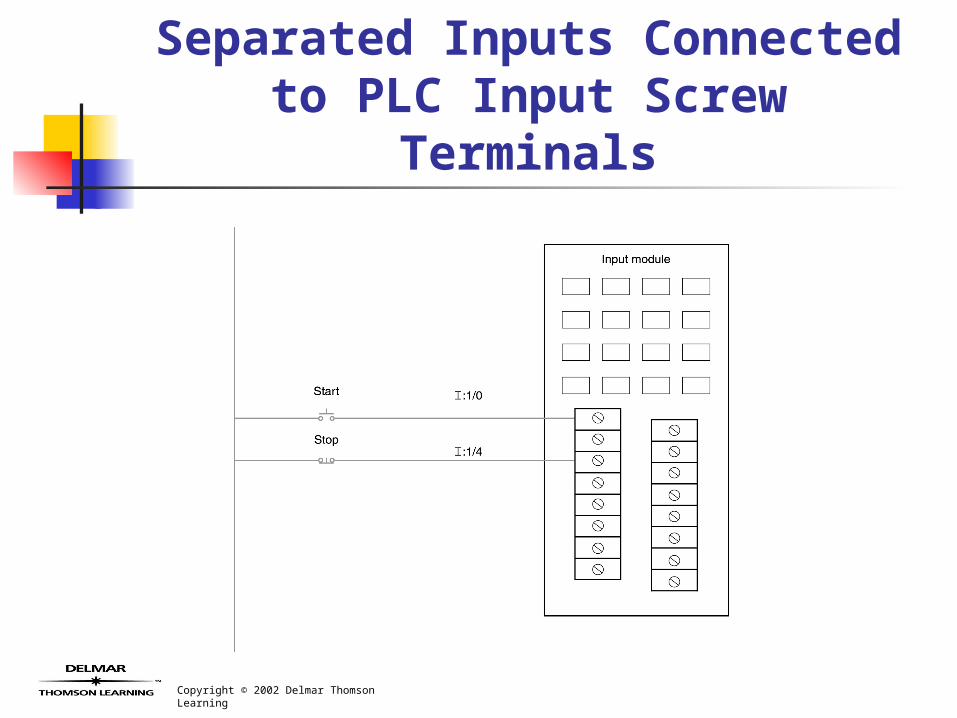
Separated Inputs Connected to PLC Input Screw Terminals

Copyright © 2002 Delmar Thomson Learning
Start Push-Button Status Reflected in the Input Status
Table

Copyright © 2002 Delmar Thomson Learning
Start-Stop Input Bit Status from Input Hardware in a Non-
Energized State

Copyright © 2002 Delmar Thomson Learning
Normally Open Push Button Not Activated

Copyright © 2002 Delmar Thomson Learning
Normally Open Push Button Input Pressed

Copyright © 2002 Delmar Thomson Learning
Normally Closed Input Push Button

Copyright © 2002 Delmar Thomson Learning
Normally Closed Push Button Input to PLC

Copyright © 2002 Delmar Thomson Learning
Push Button Released Output Latched through CR
1-1

Copyright © 2002 Delmar Thomson Learning
Conventional Schematic Start-Stop Logic

Copyright © 2002 Delmar Thomson Learning
Conventional Motor Starter Schematic Diagram

Copyright © 2002 Delmar Thomson Learning
Conventional Motor Starter Circuit Converted for PLC
System Management