copyright warning &...
TRANSCRIPT

Copyright Warning & Restrictions
The copyright law of the United States (Title 17, United States Code) governs the making of photocopies or other
reproductions of copyrighted material.
Under certain conditions specified in the law, libraries and archives are authorized to furnish a photocopy or other
reproduction. One of these specified conditions is that the photocopy or reproduction is not to be “used for any
purpose other than private study, scholarship, or research.” If a, user makes a request for, or later uses, a photocopy or reproduction for purposes in excess of “fair use” that user
may be liable for copyright infringement,
This institution reserves the right to refuse to accept a copying order if, in its judgment, fulfillment of the order
would involve violation of copyright law.
Please Note: The author retains the copyright while the New Jersey Institute of Technology reserves the right to
distribute this thesis or dissertation
Printing note: If you do not wish to print this page, then select “Pages from: first page # to: last page #” on the print dialog screen

The Van Houten library has removed some of the personal information and all signatures from the approval page and biographical sketches of theses and dissertations in order to protect the identity of NJIT graduates and faculty.

AN ANALYSIS OF PREDETERMINED TIME SYSTEMS
BY
RICHARD 0. SCHMID
A THESIS SUBMITTED TO THE FACULTY OF
THE DEPARTMENT OF MANAGEMENT ENGINEERING OF
NEWARK COLLEGE OF ENGINEERING
IN PARTIAL FULFILLMENT OF THE REQUIREMENTS FOR THE DEGREE
OF
MASTER OF SCIENCE WITH A MAJOR IN MANAGEMENT ENGINEERING
NEWARK, NEW JERSEY
1957

ABSTRACT
This paper endeavors to compare three predetermined
time systems, namely; Work-Factor, Methods-Time Measure-
ment and Basic Motion Timestudy, elemental-by-elemental,
through the use of a series of detailed analyses. The
following information in the form of conclusions and
recommendations has been set forth from the investigation
of the various comparative analyses contained herein:
I. Reasons for the variation between the
elementals.
2. A chronological order of attack for
further study with an eye to accomplishing
the most in the shortest possible time.
3. The results of a composite analysis which
utilizes the most realistic elemental
definitions of the three systems. (This
includes the comparison of the latter and
the other three systems of predetermined
time standards to the Time Study values
for the operation being analyzed).
4. An indication of which systems appear to
be the quickest and easiest to use, based
on the operation that was analyzed.
5. Recommendations concerning the selection
i i

of a predetermined time system for
actual use.
In addition, the introductory chapters acquaint the
reader generally with the Time Study Technique and the
history and operation of all of the well known systems
of predetermined time standards.
iii

APPROVAL OF THESIS
FOR
DEPARTMENT OF MANAGEMENT ENGINEERING
NEWARK COLLEGE OF ENGINEERING
BY
FACULTY COMMITTEE
APPROVED:
NEWARK, NEW JERSEY
JUNE, 1957
iv
PREFACE
The purpose of this paper is essentially to compare
three well known predetermined time systems, elemental by
elemental, in order to find out how and why they differ,
if at all, and also to determine which of the systems is
the easiest and quickest to use based on the operation
that was analyzed. Originally it was planned to analyze
a hand operation and a man-machine operation. However,
it was soon realized that either one or the other was
sufficient for the purposes of this paper, since the
fundamental motions are designated as universal and hence
found in either operation. Analysis of both would simply
have amounted to duplication. Actually it did not matter
which type of operation was chosen for analysis, as long
as the one selected "ran the gamut" of the fundamental
motions as presented by the predetermined time systems.
In short, coverage of elementals was essential.
As the work progressed, it became apparent that it
would be advantageous to analyze the industrial operation
that was selected, not only by the three standard pre-
determined time systems, but also by a "composite system"
which utilized the most realistic fundamental motion
definitions of each of those systems. This, of course,
was done with the purpose of comparing all four values to

the time study value for the operation to ascertain which
system(s) compared most favorably to time study. Of
course, the results of this phase of the analysis cannot
be as detailed nor as accurate as those described in the
first paragraph. This type of analysis done properly
would involve the use of many time studies of various
types of operations (a representative sample) with their
respective predetermined time system or "composite system"
analyses in order to statistically determine whether or
not a significant difference exists. Although this paper
considers only one operation, it appears to be a step in
the right direction and definite trends can be determined.
Chapter I acquaints the reader with the two basic
techniques for determining the standard time of an
operation - Time Study and the Predetermined Time Systems,
through a discussion of the basic concepts and individual
histories of each.
Chapter II familiarizes the reader with the princi-
ples of operation of each predetermined time system as
discussed in Chapter I, so that he might proceed to the
rest of the text and follow the various detailed analyses
contained therein.
Chapter III sets forth the actual element analyses
of a selected industrial operation through the use of
vi

each of three specific predetermined time systems. These
are Work-Factor, Methods-Time Measurement and Basic Motion
Timestudy. This is preceded by a detailed description of
the operation.
Chapter IV has as its purpose the presentation of
the various detailed breakdowns of the latter analysis in
the form of the charts, tables and discussions that are
necessary to fulfill the purposes of the thesis as stated.
Finally, Chapter V presents the conclusions derived
from a searching analysis of the results of Chapter IV,
and as well sets forth some recommendations based
primarily on those conclusions.
It is strongly suggested that the reader read each
chapter and especially the introduction to Chapter IV
before attempting to study any of the analysis charts or
discussions as presented in Chapter IV.
I would like to express sincere appreciation for the
many helpful suggestions and criticisms given me by
Professor Oliver J. Sizelove of Newark College of
Engineering. Also, grateful acknowledgment is made to
Mr. James H. Duncan, Managing Partner of the Work-Factor
Company for sending me a copy of The Detailed Work-Factor
Manual; to Messrs. Gilbert P. Blackwood and David Egan,
vii

also of the latter Company, who were kind enough to
review the technical details of the Work-Factor analysis
contained herein; to Harold B. Maynard, President of the
Methods Engineering Council who forwarded to me much
useful information concerning the application of Methods-
Time Measurement; and to my typist Miss Joan M. Schmid who
spent many tedious hours at the keyboard.
Finally, permission to quote is gratefully
acknowledged as secured from the following publishers:
The Chilton Company, Inc.
Harper and Brothers Publishers
John Wiley and Sons, Inc.
The McGraw-Hill Book Company, Inc.
The McGraw-Hill Publishing Company, Inc.
Magazines of Industry, Inc.
Prentice-Hall, Inc.
The Ronald Press Company
Society for the Advancement of Management
Richard 0. Schmid Union, New Jersey June, 1957
viii

TABLE OF CONTENTS
Title Page
Abstract ii
Approval Page iv
Preface
Table of Contents ix
List of Figures •• xiii
List of Tables xiv
CHAPTER I: INTRODUCTION TO STOPWATCH TIME STUDY AND THE PREDETERMINED TIME SYSTEMS
Background of Stopwatch Study 1
Time Study - The Definition I History of Time Study 2
Predetermined Time Systems 6 The Definition and Basic Concepts.. 6 History of Predetermined Time Systems 9 The Uses of Predetermined Time Systems 1
Developing Effective Methods in Advance of Production a 1
Improving Existing Methods 2 Establishing Time Standards 2 Developing Standard Data and
Time Formulas 3 Estimating 4 Guiding Product Design 4 Developing Effective Tool Designs 4 Selecting Effective Equipment 5 Training Supervisors to Become
Methods-Conscious 5 Settling Grievances 5 Operator Training 6
Research 6 Advantages, Disadvantages and Limitations
of Predetermined Time Systems. 6 Advantages of Predetermined Time Systems 6 Disadvantages and Limitations of
Predetermined Time Systems 8 Summary of a Survey which Determines What
132 Users Are Really Getting From PTS 9
ix

Historical Background of the Development of the Individual Predetermined Time Systems 21
History of Motion Time Analysis (MTA) 21 History of Work-Factor 22 History of Methods-Time Measurement (MTM).. 24 History of Dimensional Motion Times (DMT). 28 History of Basic Motion Timestudy (BMT) 29
Summary 30
CHAPTER I I : THE OPERATION OF THE PREDETERMINED TIME SYSTEMS
Introduction 30
Operation of Motion Time Analysis (MTA) 32 Definition and Theory of MTA 32 The MTA Basic Motions 34 The Application of MTA 36
Operation of Work-Factor 38 Definition and Theory of Work-Factor 38 The Application of Work-Factors 41 Standard Elements of Work 46 Effect of Simultaneous Elements on Time. 47 Scope and Use of the Work-Factor System 47 Making the Work-Factor Analysis 48
Operation of Methods-Time Measurement (MTM) 49 Definition and Theory of MTM 49 The MTM Basic Motions 49 Limiting Motions 55 Simplified Data 56 MTM Application Procedure 56 Why is MTM Different?.... 57
Operation of Dimensional Motion Times (DMT) 58 Definition and Theory of DMT 58 Scope of Application 59 The DMT Basic Motions 60 The Application of DMT 64
Operation of Basic Motion Timestudy (BMT) .65 Definition and Theory of BMT 65 The BMT Basic Motions 66 The Application of BMT 72
Summary 72

CHAPTER III: THE ANALYSIS OF A SELECTED INDUSTRIAL OPERATION USING THE PREDETERMINED TIME SYSTEMS
Selection of the Predetermined Time Systems to be Used in the Analysis of the Operation, "Make Cartons" 74
The Nature of the Elemental Analysis 76
Shoe We Operation - Operational Description 77
Element Descriptions of Sub-Operation 1., "Make Cartons" 79
Work-Factor Element Analysis of "Make Cartons" 86 Element I: Pick Up Carton 86 Element 2: Open Carton and Fold Ends 87 Element 3: Place Carton on Stapler 89 Element 4: Staple Carton Ends 90 Element 5: Set Carton Aside 92
MTM Element Analysis of "Make Cartons" 94 Element I: Pick Up Carton 94 Element 2: Open Carton and Fold Ends 95 Element 3: Place Carton on Stapler 97 Element 4: Staple Carton Ends 98 Element 5: Set Carton Aside...., 00
BMT Element Analysis of "Make Cartons" 01 Element 1: Pick Up Carton 101 Element 2: Open Carton and Fold Ends. 02 Element 3: Place Carton on Stapler 04 Element 4: Staple Carton Ends 05 Element 5: Set Carton Aside 06
Summary 08
CHAPTER IV: COMPARISON OF THE ELEMENTALS
The Nature of the Analysis 110
Element 1: Pick Up Carton Comparative Analysis 116 Discussion: Element 1 117
Element 2: Open Carton and Fold Ends Comparative Analysis 121 Discussion: Element 2 124
xi

Element 3: Place Carton on Stapler Comparative Analysis 133 Discussion: Element 3 134
Element 4: Staple Carton Ends Comparative Analysis 138 Discussion: Element 4 140
Element 5: Set Carton Aside Comparative Analysis 146 Discussion: Element 5 147
Cycle Time Weighted 5 Difference Analysis 151
Composite Analysis 154
Summary 157
CHAPTER V: CONCLUSIONS AND RECOMMENDATIONS
Conclusions 158 Comparison of the Elementals 158 Use of the Systems 165
Composite Analysis 165 Which System is Quickest and Easiest
to Use? (Based on the Operation that was analyzed) 167
Recommendations 168 Concerning Further Study of the Predetermined Time Systems 168
Comparison of the Systems One to Another (Elementals) 168
Comparison of the Systems to Time Study 169 Concerning Use of the Systems 170
Composite System 170 Standard Systems 172
CHAPTER VI: CRITICAL EVALUATION 174
Bibliography 181
xii

LIST OF FIGURES
Figure I. Basic Steps in the Opening and
Subsequent Stapling of the Carton 83
Figure 2. Acme "Silver Stitcher" Stapling
Machine; Motion Path of Stapling
Operation ....84
Figure 3. Layouts: Shoe Welting Operation and
"Make Cartons" Stapling Operation 85
xii

LIST OF TABLES
Table 1: Work-Factor "Arm" (A) Motion-Time
Table 44
Table 11: MTM "Reach" (R) Motion-Time Table 51
Table 111: DMT "Grasp - Jumbled Parts in Trays -
J" Motion-Time Table 63
Table IV: BMT "Reach and Move" Motion-Time Table 67
Table V: Time Value Summary Sheet 107
Table VI: Summary of the Discussion.-
Element 1 120
Table VII: Summary of the Discussion.-
Element 2 132
Table VIII: Summary of the Discussion.-
Element 3 137
Table IX: Summary of the Discussion,-
Element 4 145
Table X: Summary of the Discussion.-
Element 5 150
xiv
CHAPTER I
INTRODUCTION TO STOPWATCH TIME STUDY AND THE PREDETERMINED TIME SYSTEMS
BACKGROUND OF STOPWATCH STUDY
Time Study - The Definition
What is Time Study? Presented below may be found the
definitions of Time Study as seen by several notables in
the field:
"Time Study - A searching scientific analysis of methods and equipment used or planned in doing a piece of work, development in practical detail of the best manner of doing it, and determination of an accurate time standard."'
Barnes states "Common practice today requires that motion study and time study be used together since the two supplement each other. Motion and Time Study is the analysis of the methods, of the materials, and of the tools and equipment used, or to be used, in the perfor-mance of a piece of work - an analysis carried on with the purpose of (I) finding the most economical way of doing this work; (2) standard- izing the methods, materials, tools and equip-ment; (3) accurately determining the time required by a qualified person working at a normal pace to do the task; and (4) assisting in training the worker in the new method."2
"A Stop-Watch Time Study is used to find the amount of time necessary to accomplish a unit of work, using a given method, under given
1. Morrow, Robert Lee, M. E. Time Study and Motion Economy. New York: The Ronald Press Company, 1946. p. 104.
2, Barnes, Ralph M., M. E., Ph. D., Motion and Time Study, Third Edition. New York: John Wiley & Sons, inc., 1949. p. 1

2
conditions of work, by a worker possessing a specified amount of skill on the job and a specified attitude for the job, when working at a pace that will produce, within a unit of time, a specified physical effect upon him. The time obtained is called standard time."3
From the foregoing definitions, it may be seen that
theory holds that Time Study is not merely the setting of
a rate for a job, but also a determination of the proper
method for doing that job before any Time Studies are
taken. However, in actual practice this, many times, is
not so. Many rates are set by the stopwatch with little
or no methods analysis preceding the Time Study. This
serves as one excellent explanation for the widespread
use of predetermined time systems, namely; the use of
such a system is in effect a "forced" methods analysis.
The analyst must look at methods in order to use the
system at all.
History of Time Study4
The first known time studies were made in 1760 in
France by M. Perronet. Following this in 1830 the
English economist, Charles Babbage, also made a series of
time studies. Coincidentally, both men concerned them—
selves with studying the manufacture of pins. Everything
3. Mundel, Marvin E., Ph. D., Systematic Motion and Time Study. New York: Prentice—Hall, Inc., 1947. p. 128.
4. Ibid. I, pp. 69-71.

3
indicates that the studies of these men were of the type
which merely indicated a total time for the completion of
a stipulated amount of production.
Frederick W. Taylor "The Father of Scientific
Management" is credited with taking the first time studies
in the United States.
"So great has been Taylor's contribution to the whole problem of effective utilization of human effort in industry that we can profit from a review of his work in this field. Taylor came from a well-to-do Philadelphia family, was trained at Phillips Exeter Academy to enter Harvard, and after but a year and a half at Phillips Exeter passed the Harvard entrance examinations with honors, but at the cost of seriously impaired eyesight. Forced to give up the idea of further study, at the age of eighteen he obtained a job in a machine shop where he served the apprentices of machinist and pattern-maker. In 1878 when he was twenty-two he went to work at the Midvale Steel Works. As business conditions were bad at that time, he took a job as an ordinary laborer. He was rapidly promoted to time clerk, journeyman, lathe operator, gang boss, foreman of the machine shop, and at the age of thirty-one was made chief engineer of the works. During his early years at Midvale, Taylor studied at night and in 1883 obtained a degree in mechanical engineering from Stevens Institute."5
Taylor's time studies were taken at the Midvale Steel
Company in 1881 and were vastly different from those taken
by Perronet and Babbage. The time studies were quite
5. Ibid. 2, p. 9.

4
detailed in nature, requiring that the job be broken down
into basic motion groups or elements for which individual
times had to be established. In 1883, E. H. Miller was
hired to help Taylor in the organization of a Time Study
Department. It is interesting to note that Taylor's idea
of taking time studies came to him while he was a student
at Exeter. His mathematics professor made a practice of
timing the students with a stop watch as they did their
problems.
After 12 years experience with Time Study at Midvale,
Taylor presented a speech at the Detroit Meeting of the
American Society of Mechanical Engineers which related
the findings of his work. This proved to be a most
disappointing experience for Taylor, since many of the
prominent engineers of the day completely missed his
message. They wrongly concluded that Taylor was primarily
discussing a piece rate system of wage payment rather
than a new technique which measured the amount of time
necessary to complete an operation.
It was, however, in June 1903 when Taylor presented
his paper "Shop Management" to the American Society of
Mechanical Engineers that a more favorable response
resulted. Many progressive factory managers gave the new
Time Study Technique much favorable attention, and it was
quite successfully used in many plants. However, at the

5
Watertown Arsenal, time study was not well received by
labor, and after an Interstate Commerce Commission
Investigation, Congress attached a rider to the govern-
ment appropriation bill in 1913 which in effect stipulated
that no pay be made available for any time study personnel.
The rider was eliminated on August 26, 1948 during the
Proceedings and Debates of the 81st Congress, 1st Session.
This was accomplished largely through the efforts of such
men as John W. Nickerson and Phil Carroll, Jr.
Far from being discouraged by this, Taylor was most
happy to hear that the American Society of Mechanical
Engineers' Report for 1912 reviewed the Time Study
Technique and concluded that when properly administered,
it has contributed to the good of the human race. This
conviction has been upheld from that time on by the
Society and by other groups.
After retirement Taylor embarked upon one of his
great dreams, namely; to begin a review of all unit times
that had been recorded. This was to be done in collabo-
ration with Dwight V. Merrick and unfortunately was
interrupted by Taylor's death. The work was started
again by Merrick and other of the followers of Taylor.
Merrick also wrote the first complete book on time
studies in the United States which fully explained the
applications and uses of Time Study. The book is

6
entitled "Time Studies as a Basis for Rate Setting" and
was published in 1920.
Since 1917 the Taylor Society, which in 1936 merged
with the Society of Industrial Engineers to form the
Society for the Advancement of Management, has undertaken
the Time Study work. The American Society of Mechanical
Engineers, the American Management Association and the
American Institute of Industrial Engineers are continuing
to publish papers on Time Study that are presented before
them.
One final word about Taylor, "One cannot read Taylor's experiments on the art of cutting metals, his study of rest pauses in handling pig iron, or his investigations in shoveling without at once realizing that he was a scientist of high order. With Taylor, as with the factory manager today, Time Study was a tool to be used in increasing the overall efficiency of the plant, making possible higher wages for labor, and lower prices of the finished products to the consumer."6
PREDETERMINED TIME SYSTEMS
The Definition and Basic Concepts
"Predetermined Time Standards (PTS) is our term for time standards developed from basic motion study data for fundamental manual motions. Grouped into tables covering a complete set of basic manual motions, these standards provide
6. Ibid. 2, P. 12.

7
a system for measuring manual work."7
It has been the goal of the industrial engineer since
the time of Taylor to develop a system of work measure—
ment which was broad enough to be applicable to every
existing job and yet defined to a point where interpre—
tation posed no great problem. In its initial stages
this type of thinking referred to the assignment of time
values to operations that were being timed and retimed
throughout the country, such as pushing buttons, stepping
on footpedals, etc.; and that eventually all existing
operations in industry would have a time value attached
to them. Then, after classification in a text or manual
these values were to all but eliminate stop watch time
study.
This concept has remained, with one notable
exception (A. B. Segur), until quite recently somewhat
more of a dream than a practical reality because industry
claimed that even if such a manual were developed, it
would be so bulky and complicated as to render it
impractical to use.
A reconsideration of the problem, however, brought
7. "Predetermined Time Standards", Factory Management and Maintenance, Vol. III, September, 1953. p. 134.

8
about the conclusion that the fallacy was based on the
conception of an element time. The time study element
such as "pick up hammer", "nail wood in place", etc.,
indeed would be difficult to classify in such a volume.
It may readily be seen that elements such as these for
the various trades would be infinite in number. Hence
the "element" of Taylor and Frank B. Gilbreth's further
subdivision of the element into "therbligs" had to be
replaced by the modern industrial engineering concept of
fundamental or basic manual motions (elementals).
Gilbreth had pointed out in his concept of universal
elementary motions that of all jobs, the same elementary
motions were used "in various combinations and sequences".
Gilbreth's concept was sound, indeed it is the basis of
all modern predetermined time systems, however, it
remained for later work to uncover the further sub-
division and/or combination of the "therblig" into the
fundamental manual motion or elemental.
The efforts made in determining the meaning and
magnitude of these fundamental manual motions were
expended essentially to attempt to provide a table of
standard time values for body motions that are common
to all jobs such as reaching, moving and grasping. These
timetables as recently developed are based on many stop
watch and/or motion picture time studies. Using the time-
tables, the standard time for an operation may be built

9
up by determining first just exactly what the operator
DOES during the operation, and then analyzing these
motions and breaking them down into the elementary
motions, picking the values off the timetable for each
elementary motion and taking the sum of these times to
determine the total "standard" (base) time for the
operation.
For example, the operation "sign name" would be
broken down into, "Reach 12 inches for pencil, grasp
pencil, move pencil to paper 15 inches", etc. The total
motion time is given by summing the times for each funda-
mental motion as it is selected from the motion timetable.
This in essence, is the thinking upon which Predetermined
Time Systems are based.
History of Predetermined Time Systems
As mentioned in the section previous to this, the
work of Taylor and Gilbreth paved the way to the Pre-
determined Time Systems of today. Taylor by his contem-
plation of standard times for "every element in every
trade" and Gilbreth by determining his fundamental 18
motions (therbligs) which, if used in various combinations
could identify any element of any job.
After the work of these two pioneers, the first
person to attempt to establish a predetermined time
system through an appreciation of time as it concerned

10
a methods analysis was A. B. Segur in the early 1920's.
Even though this work was essentially confined to his
clients, his technique of minute motion breakdowns of
body members and the assignment of physiological values
to the muscle structures which caused the movements was
a great stride forward in the field of Industrial
Engineering. Today, Segur's system is known as Motion-
Time-Analysis (MTA). This approach, which was especially
applicable to the repetitive manufacture of small parts
became of great interest to General Electric in the
early 1920's. General Electric's original time standard
plan represented the first classification of predetermined
time standards for specific hand and body motions for
specific types of work.
It was the work of three industrial engineers at the
Radio Corporation of America beginning in 1934, which
brought forth the first system of real practical value.
This system, known as the Work-Factor System was
developed by Messrs. J. H. Quick, W. J. Shea and R. E.
Koehler and has since received widespread acceptance in
industry. In 1940, H. B. Maynard of Westinghouse
conducted an intensive study of sensitive drill press
work which later developed into the Methods-Time Measure-
ment (MTM) system of predetermined time standards. Other
recent systems worthy of mention are the Dimensional

11
Motion Times system of H. C. Geppinger, and the Basic
Motion Timestudy system of Ralph Presgrave.
The Uses of Predetermined Time Systems8
The following uses for predetermined time standards
have been set forth by industry, schools and colleges:
"Developing effective methods in advance of beginning
production". The reluctance with which the worker accepts
a methods change is a well known fact and is based upon a
fear that he may lose his job. Nevertheless Taylor has
stated that:
"Complete standardization of all details and methods is indispensable to specifying the proper time in which each operation shall be done and to insisting that it shall be done in the time allowed."9
It is of prime importance to apply this principle on any
new job so as to avoid worker ill feeling later on and to
produce the product at the lowest possible cost. Pre-
determined time standards lend themselves ideally for
application in this area and provide, as well, pre-
determined instruction cards for each job before the
8. Maynard, H. B., Editor-in-Chief, Industrial Engineering Handbook, First Edition. New York: McGraw Hill Book Co., Inc., 1956. pp. 4-3 to 4-13. (ALL THE HEADINGS OF THIS SECTION ARE QUOTED FROM THIS TEXT)
9. Taylor, Frederick Winslow, Shop Management. New York: Harper and Brothers Publishers, 1912. p. 123.

12
method is instituted on that job. All of this could be
most instrumental in eliminating many industrial relations
difficulties.
"Improving existing methods". The work of the methods
engineer never stops because the method of a job never
ceases to change. Predetermined Time Standards are
particularly applicable to this area because of the nature
of the system. The analyst is, in a sense, forced to
examine the operation step by step, and motion by motion.
A questioning attitude is raised as to which motions are
really necessary, and it is indeed most difficult to find
an operation that could not be improved. A justification
of the importance of this use of predetermined time systems
is the following fundament of Taylor:
"The greatest permanent prosperity for workman and employer comes from doing work with the smallest expenditure of human effort, natural resources and invested capital."'°
"Establishing time standards". Here as has been
previously discussed, method of application is quite
simple after adequate training and experience has been
gained in the field of predetermined time systems.
Standard time for an operation is merely a summation of
the times required to perform each basic motion as
10. Ibid. 9, p. 10.

13
presented in a motion time table.
Use of these systems effects a great savings in the
amount of time required to study a job, and at the same
time imposes a motion study on that job. Though many
uses exist for predetermined time systems, it is the
opinion of the author that this is the use which stands
well above any of the others in importance. Taylor wrote
that time study is the cornerstone of Scientific Management;
predetermined time systems strive to determine time in a
consistent manner. Their basic principle is scientifically
sound.
"Developing standard data and time formulas". Time
formulas or standard data is the means by which large
numbers of consistent standards may be set on a given class
of work. This is generally done by the laborious time
study method through compilation of standard element times
from a representative group of time studies. For certain
types of work predetermined time systems may be used to
much advantage, since the results will be developed con—
sistently through a knowledge of the proper method.
Constant and variable elements that are not process
controlled may be easily determined by a predetermined
time system, and combined to form the desired time formula
in a fraction of the time required by the time study
technique. Curve plotting methods may aid greatly in the
development of time formulas.

14
"Estimating". Estimating labor costs for large
quantities of repetitive work so that an accurate cost
might be quoted to a potential customer is one of the
more important applications of a predetermined time
system. It may readily be seen that use of this method
will be far more time consuming than use of conventional
"rule-of-thumb" estimating methods, but if the quantity
of production is large and exact estimates are required,
then use of such a system is fully justified.
"Guiding product design". Refinements in design may
be effected if en industrial engineer analyzes the manu-
facture of the part through a motion-by-motion analysis
with a predetermined time system. Hence, suggestions may
be made before the part is designed and/or jigs and tools
are built which, in turn, may reduce the work and cost of
manufacture.
"Developing effective tool designs". A tool designer's
final choice of design may be based upon such considerations
as accuracy obtainable, tool life, cost and handling time
necessary. The least amount of handling time may not
necessarily mean lowest cost, but generally this is a
desirable condition. Predetermined elemental times,
through a visualization of the method of use, are a great
aid to the tool designer in a predetermination of the
least handling time.

15
"Selecting effective equipment". When one is consider-
ing the purchase of a piece of machine tool equipment for
a job he would naturally want the machine which could be
manipulated most quickly and easily. Through use of a
predetermined time system analysis (visualizing motions)
as outlined in the preceding paragraphs, the proper
conclusion might be arrived at in a short period of time.
"Training supervisors to become methods-conscious".
The supervisor is the man who should instruct his personnel
in the proper methods of doing their work. In order to do
this the supervisor should be able to analyze a job through
use of the basic motions as prescribed in any predetermined
time system. The analysis should then indicate to the
supervisor the motions required to perform the job and the
layout of the workplace. He should be able to explain and
demonstrate the method to the worker.
"Settling grievances". Many workers are reluctant to
accept the validity of time study standards due to the
judgement involved in rating the original times. However,
a foreman trained to analyze basic motions can generally
settle a standards grievance at his own level by showing
the worker the exact motions required to perform his job.
This demonstrates satisfactorily to most workers that the
job may be done in the prescribed time if the exact method
is used, but if extra motions are introduced then the

16
reason for the supposed "tightness" of the standard is
evident. It must be realized, however, that the above is
not wholly true, in that judgement is indeed brought to
bear in the selection of the fundamental motions used in
any analysis, and of course judgement in the form of
rating was used in the gathering of the original data of
each predetermined time system.
"Operator training". The teaching of motions in the
form of reaches, grasps, etc. along with a presentation
of corresponding time values has been a great aid in
operator training in recent years. This is so because the
operator will become motion conscious, and will be able to
easily recognize and eliminate wasteful motions.
"Research". Predetermined time systems are a tool
whereby knowledge about methods and time in general can
be increased greatly. Examples of research projects
might be a study of how methods vary as the operator
learns to do a new operation, and the learning time
required for same. There exist many fascinating studies
of this type for one interested in research. (Also, see
Recommendations For Further Study in Chapter V of this
manuscript).
Advantages, Disadvantages and Limitations of Predetermined
Time Systems
Advantages. "I. The judgement factor involved

17
in the rating of individual operators is eliminated. (The author is not in full accord with this. Judgement used in rating is not eliminated through the use of a predetermined time system. It is merely bypassed, since such judgement was used in gathering the original data).
2. The job breakdown and analysis of individual motions necessary to assign time values from the tables encourage improvement in work methods; and provide an accurate, minute description of each job that serves as a record for future reference.
3. Time estimates can be made before a job starts running, even if it has never run before.
4. Building up work standards from tabular data is faster and more accurate, particularly for short jobs, than time study, if the engineer knows exactly what will take place on the job.
5. Because times are obtained from a table they are consistent." 11
John S. Kelly of Sargent & Company, New Haven,
Connecticut enthusiastically reports about predetermined
time standards as follows:
"Of even greater value than the tremendous time savings of these work sheets is the consistency of the rates. The operators know that the same application of skill and effort will always result in their same level of earnings. This does away with one of the foreman's greatest problems. There are no 'tight' or 'loose' rates that he has to watch to see that they are equally divided. He can move any job to any operator and know the operator's or group's earnings will not be affected.
II. "Short Cuts To Productivity", Modern Industry, Vol. 19, May 15, 1950. p. 44. (parenthesis added)

18
Many doubts and questions may be answered at this point by a few simple statements of resultant facts.
1. Required production per man hours was considerably raised.
11. Workers made bonuses. III. Quality was maintained or increased
where necessary. IV. Training became remarkably efficient. V. Grievances over rates now were reduced
to, 'What did you do? What was the condition of the incoming part?' A change in work or quality resulted in an instant change in rate or a special allowance for a run of poor stock." 12
Disadvantages and limitations.
"I. Since the various tables of motion differ, there is some question about their accuracy. They can't all be exactly right.
2. It has not been proved that a given motion will have a fixed time value, regardless of the motions which precede or follow it.
3. Stop watch studies or other techniques are still necessary for machine controlled elements of jobs, for drilling and cutting time, and the like. Furthermore, tabular systems do not solve such problems as the number of passes which must be made with a grinding wheel to secure the proper surface quality on a given type of part.
4. To obtain data that will be usable in the shop, it is still necessary to prepare standard data charts. This part of the work may require by far the larger part of the time, so that the timesaving, even on short jobs, is not always as great as it may seem.
5. The fact that time standards can be set without ever observing the job in the shop may lead the unwary and untrained user of these systems into two traps:
a. The 'ideal' motion pattern established by an engineer working in the office may be very different from the pattern used by operators on
12. Kelly, John S., "Establishing Finishing Operation Rates With Elemental Time Standards", Metal Finishing, Vol. 49, March, 1951. p. 74.

19
the production line. b. If motions are missed in the job
analysis, standards will be 'tight' (not enough time will be allowed). If motions are duplicated, standards will be 'loose'. Thus, one or two stopwatch time studies are very often necessary - not only to check standards, but also to provide a record for use in union nego-tiations."13
Summary of a Survey Which Determines What 132 Users Are
Really Getting From Predetermined Time Standards14
The following five questions represent the results
of a survey conducted by Factory Management and
Maintenance in 1953:
1. "What will Predetermined Time Standards (PTS) do
for you?"
A series of basic questions such as: To what
extent has your system resulted in - (1) shop changes?
(2) elapsed time to develop incentive or methods?, etc.
were asked and the answers to them indicate a high degree
of satisfaction with PTS. The amount of dissatisfaction
was very small. "Nine out of ten (87%) cite better shop
methods as a benefit."
2. "What's the future of PTS?"
"Nine out of ten users (92%) say they plan to
increase their use of PTS." One reason for this might.
13. Ibid. II, p. 44.
14. Ibid. 7, pp. 134-139. (ALL THE QUOTES IN THIS SECTION ARE TAKEN FROM THIS TEXT EXCEPT WHERE OTHERWISE NOTED)

20
well be that PTS acquires many more uses in a company
after the company has gained experience with the system.
3. "How accurate are PTS?"
"Almost all users (97%) agree that PTS are
accurate enough." In other words from a practical stand-
point it is the general consensus of opinion that PTS
are as accurate as can be expected where human judgement
is involved.
4. "Is the stopwatch out?"
"Four out of five users continue to use the
stopwatch" (to supplement PTS studies). This conclusion
is in complete agreement with Harold Engstrom of Sylvania
Electric Products, Inc. who speaking at a Management
Conference at the University of Connecticut in 1952,
stated:
"Verification time studies should be insisted upon as an assurance that we are not digressing too far from normal. This might seem contra-dictory but we still have this problem of operator aptitude, managerial climate and war conditions for which we have yet to devise a measuring stick. Despite the great advances made in synthetic values, we cannot at this point consider them as substitutes for time study measurement. They are rather an aid, supplement and guide for better and improved standards determination."15
IS. Engstrom, Harold, "Predetermined Time Standards", Advanced Management, Vol. 17, April, 1952. p. 17.

21
5. "What it takes to install PTS."
"You'd better call in a consultant". Experience
must be brought to a PTS installation at the very outset.
It may readily be seen that due to the complicated nature
of some of the systems, training by competent personnel
is necessary to eliminate many of the "bugs" and
unfamiliarities with the intricacies of the system being
used.
HISTORICAL BACKGROUND OF THE DEVELOPMENT
OF THE INDIVIDUAL PREDETERMINED TIME SYSTEMS
History of Motion-Time-Analysis (MTA)
As was mentioned earlier, A. B. Segur, now of
A. B. Segur and Company, Oak Park, Illinois was the first
to establish a predetermined time system (early 1920's)
through an appreciation of time as it concerned methods
analysis. Originally the system was used for setting
rates, but eventually came to be used primarily as a mean
of methods control.
"The first key to the time equations of Motion-Time-Analysis was discovered in 1924 by analyzing micromotion films taken of expert operators in World War I. These films were originally taken with the view of discovering a means of training blind and other handicapped workers to perform useful industrial tasks. The workers studied were the best available in the industry. At the time this analysis was made, Gilbreth's motion classification was already available as an aid.
22
After careful study of the work of these experts, it was discovered that, 'Within reasonable limits, the time required of all experts to perform a time fundamental motion is a constant.'
In the above statement, 'reasonable limits' can be taken to mean 'industrial limits'. It was recognized that there would be a slight difference between the time required for various expert operators to perform an identical motion, but that a fairly wide limit existed within which it was possible to control industrial operations. As a result of 28 years of experience, it can be stated positively that the greatest average variation in the speed of normal individuals will be from 10 per cent below normal speed to 10 per cent above normal speed."16
Even though the work of Mr. Segur was essentially
under wraps, being confined to his clients, his technique
of minute motion breakdowns of body members and the
assignment of physiological values to the muscle
structures which cause the movements was a great stride
forward in the field of Industrial Engineering.
History of Work-Factor17
Work-Factor was originated in Philadelphia,
Pennsylvania in 1934. The original concept was a product
of Joseph H. Quick who is now the president and general
manager of the Harrington and Richardson Arms Company.
He was assisted by William J. Shea, who is now vice-
16. Ibid. 8, p. 4-102.
17. Ibid. 8, pp. 4-42 to 4-43.

23
president of the H. H. Brown Shoe Company. Also assisting
was Robert E. Koehler now plant manager of the Capehart—
Farnsworth Corporation. The original work of data
collection was done by a staff of 12-25 engineers through
the year 1937 and was made by studying a sample of about
1,100 experienced factory employees. The studies were
made during working hours under normal factory conditions
of experienced workers who varied in skill, ability and
effort expended.
Approximately 17,000 motions were studied using a
watch calibrated in thousandths of a minute and also
photoelectric timers and 16 MM motion picture cameras for
extremely short motions and varied complex situations.
Stroboscopic photography in the laboratory was used to
verify much of the shop data.
Two to five engineers worked simultaneously, but
independently in rating the performance of each operation
by individual motion and total operation cycle. Nothing
was accepted until the sum of the leveled times for the
individual motions matched the leveled time for the total
cycle.
The original data was tabulated in the form of
curves and later in the more convenient tabular form of
the Motion—Time table.

24
The final time values as they appear in the motion-
time table represent times required by "an average of
experienced workers" as set forth by experienced engineers.
The first actual shop applications were made in
Camden, New Jersey in 1938. Some 220 engineers were
trained to use this system in the setting of production
standards through 1945, The Camden manufacturing firm
involved employed about 10,000 persons.
During this seven year period the original data was
refined as problems presented themselves in the shop, and
hence the time tables were revised to conform with the
corrected data. In 1945, the time values and a short
explanation of Work—Factor were published in the magazine,
"Factory Management and Maintenance". Since that time
there have been few changes in time values, but work has
been expended in attempting a further standardization in
the rules and procedures for using them. This development
since 1945 has been under the direction of James H. Duncan,
Managing Partner of the Work—Factor Company.
History of Methods—Time Measurement (MTM) 18
The basic thinking behind the MTM predetermined time
system originated in the mid—twenties with Harold B. Maynard,
18. "Timing a Fair Day's Work", Fortune, Vol. XL, October, 1950, pp. 129-132+.
25
then a recent Cornell graduate, who was engaged in time
study work for Westinghouse in Pittsburgh. His supervisor
was Gustav J. Stegemerten, the Superintendent of Wage
Incentives. The initial work of the two men consisted of
the determination of a concept of performance rating from
which a definition of average performance was developed.
From this, although unknowingly at the time, came the
underlying definition of MTM. Average performance was
that which could be expected of the conscientious worker
being paid the going wage.
The definition of average performance eventually led
to, through the work of Maynard and Stegemerten, a system
of using numerical factors to level time study data in
accordance with their performance rating system. In 1940
both men put these leveling factors together on the
problem which eventually led to the development of MTM.
By this time Maynard was heading up his own consulting
firm - the Methods Engineering Council.
Soon, Maynard and Stegemerten using the data acquired
during a methods-improvement program at Westinghouse,
studied the performance times of the various job motions
in this data. When their leveling factors were applied,
the average times all seemed to fall along well defined
curves. The work continued for another year as sensitive
26
drill press operations were minutely studied using 16 MM
motion pictures.
"The camera used was driven by a constant speed motor. Thus, with the film exposed at a constant speed, the use of timing devices and other distracting accessories was eliminated, enabling the operator to work under normal operating conditions. The film was exposed at 16 frames per second. Exposure at a slower speed made it more difficult to analyze the film in the early research phase of MTM development because element starting and stopping points were not easily identifiable.
Body, leg and foot motions were derived later by detailed time study, assisted by already developed MTM data. Simultaneous equations and statistical methods were employed to determine the published time standards." 19
The work involved breaking down Gilbreth's basic
elements or "therbligs" still further into basic motions,
since their scope and coverage was too broad and was
essentially indefinable.
In 1943 the drill press standards were being put to
the test in various companies in Pittsburgh. At this
point Jack Schwab, an extremely intelligent Westinghouse
employee began to assist the men. It was Schwab who
suggested an even finer breakdown of the data to cover
each motion when it was found one day that the data was
inapplicable to a specific type of drill press. Further
19. Ibid. 8, p. 4-17.

27
film studies found the standard time values to check out
perfectly.
MTM worked so well at Westinghouse that other com-
panies fast became interested, and it was even taught
by Schwab at the Bridgeport Engineering Institute. In
1946 Schwab and Stegemerten joined the Methods Engineering
Council, and by 1949 there were nine MTM experts who were
showing other engineers how to apply the system.
" in the last year, (1951) MTM has gained many champions. About 50 companies - including DuPont, Robertshaw-Fulton, and some divisions of G. E. - have put MTM to use. There is sub-stantial evidence that the new management tool helps improve operator training, machine design and selection, etc.
The Methods Engineering Council found that opportunities for the technique were becoming too big for it to handle. About a year ago, (1950) competitors of the Council were offered, and accepted training in MTM.
This summer (1951), 'The MTM Association for Standards and Research' was formed Harold B. Maynard of MEC, is president
At its first meeting in Toronto last month, (1951) the MTM Association announced its objectives: to coordinate research, to ex-change techniques, to establish standards and (ultimately) issue licenses, and to widen acceptance for the proper use of MTM.
Thus the industrial consultant field has taken another step showing evidence of a desire to raise its professional sights."20
20. "Methods Time Measurement", Modern Industry, Vol. 22, August 15, 1951. p. 78. (DATES IN PARENTHESIS ADDED BY THE AUTHOR)
28
History of Dimensional Motion Times (DMT)
The original work for the predetermined time system
known as Dimensional Motion Times was developed by
Harold Engstrom and his associates at the General Electric
Company in Bridgeport, Connecticut. Originally, the data
was used for estimating direct labor costs, and finally
for time standards. The research was eventually taken
over by Mr. H. C. Geppinger, Supervisor of Time Study
Training, who pursued the system to its completion and
publication in book form.
"The research project, , was carried on in great detail with an equitable number of samples and under closely controlled specifications and conditions. About 350,000 test runs were made, recorded and analyzed on nearly 1,000 test samples from September, 1949 to December, 1951. The project also included producing and analyzing 300 laboratory films and numerous test applications to known shop operations to reconcile and verify the data at several stages of the project."21
The entire DMT system, its use and application has
been recently presented in a textbook by Mr. Geppinger
entitled "DMT Dimensional Motion Times, Development and
Application", published in 1955 by John Wiley and Sons,
Inc.
21. Geppinger, H. C., "New Motion Time Method Defined", The Iron Age, Vol. 171, January 8, 1953. P. 106.

29 History of Basic Timestudy (BMT)22
Basic Motion Timestudy was developed by J. D. Woods
and Gordon, Limited, Ralph Presgrave was instrumental in
this development. The date of introduction was 1950, which
was preceded by approximately four years of research that
considered the scope, validity and timeliness of the
predetermined times as an extension of the standard data
technique.
The first experimentation dealt with a close analysis
of actual factory operations. This experimentation
followed the requirements of the "synthetic" system which
are as follows:
I. Identifiable units of movement,
2. No overlapping of units of movement.
3. The sum of units of movement must yield the
proper total time for the operation—in—question.
Finally, the first experimentation inferred that
there exist external factors (other than distance etc.)
which affect a basic motion. An example of this might be
weight carried, or care exercised in performing a basic
motion.
The second stage of experimentation concerned
itself with introducing these variable external factors
22. Ibid. 12, pp. 4-91 to 4-92.

30
singly and/or in combination with a basic motion and
measuring the results under rigid control.
These analyses were checked out against actual
factory operations and confirmed or modified if the need
arose. Motion picture analysis supplemented all studies.
SUMMARY
Chapter I essentially has a two-fold purpose, namely;
that of acquainting the reader with the two basic tech-
niques for determining the standard time of an industrial
operation - Time Study and Predetermined Time Systems.
After reading Chapter I, the reader should have an
appreciation of the meaning and history of the Time Study
Movement in the United States. In addition, he will have
become generally acquainted with the individual histories
of each of five well known systems of predetermined time
standards; and should have acquired a basic knowledge of
the meaning, fundamentals, uses, advantages, and dis-
advantages of those systems in general.
The chapter should have given the reader enough of
a background, so that he might be able to proceed to a
more detailed description of the operation of each of the
individual predetermined time systems.
CHAPTER II
THE OPERATION OF THE PREDETERMINED TIME SYSTEMS
INTRODUCTION
All of the Systems of Predetermined Time Standards
operate in essentially the same way. Each is involved
with breaking a job down into its basic fundamental
motions. An example is in order at this point: Picking.
up a pencil from a table is not a fundamental motion. It
is not universal - it is not a fine enough breakdown.
Rather, the following becomes the basic elemental motion
breakdown:
Move hand to pencil
Close fingers to grasp pencil
Move arm to pick up pencil
Motions such as the above are universal in nature and
the predetermined time systems each set forth tables of
values for those motions as well as for others. These
include reaching, moving, grasping, turning, positioning,
etc.
Hence, after an operation is described as above, the
proper motion-time value may be taken from the motion-time
table being used, and that figure will represent the base
time for the motion. The summation of all base times so
obtained will yield the base time for the entire element
or cycle.

32
The next pages will endeavor to present the methods
of operation of five of the most popular systems of
predetermined elemental times, presented in the
chronological order of their appearance on the industrial
scene,
OPERATION OF MOTION-TIME-ANALYSIS (MTA)23
Definition and Theory of MIA
Motion-Time-Analysis is the system of predetermined
time standards developed by A. B. Segur, which was
originally used in a rate setting capacity, but more
recently has been used more and more for methods control.
The following, in the words of Mr. Segur, best
describes the basic concept of MTA:
"The basis of Motion-Time-Analysis lies in the theory now rather widely accepted among physiologists that the mechanism of the human body is primarily a chemical engine. Each action of the body is the result of some chemical action that takes place within the body. Since this chemical reaction takes place in a constant temperature - insofar as the chemical reaction is constant - the time for the reaction will also be constant within narrow limits.
The controlling time for human action may be defined as follows:
Average speed of a nerve reaction in the human body is 0.000045 minute per foot of distance
23. Ibid. 8, pp. 4-101 to 4-118.

33
traveled. Average number of messages that can be started over any one nerve path in the body is 5000 per minute. Average time for a single sarcostyle to complete a contraction in response to a nerve impulse is 0.00064 minute.
In actual practice over nearly 30 years, these times have been found to hold. The units into which these reaction times are built depend entirely upon the intended use of the data. For a fixed use, they can be built into a simple set of standards, which can be memorized in I or 2 hours.
In the use of Motion-Time-Analysis, the deter-mination of the synthetic time for performing an operation is the simplest part of the entire procedure.
The above times apply to routine thinking, as well as to muscular reaction. These reactions, which are controlled by the brain, are becoming increasingly more important in industry than those which are controlled by the muscles
alone." u24
It is extremely important in applying MTA, to observe
in meticulous detail, each minute movement that is made
and to set it down in longhand, so that the developed time
values may be applied. These minute movements may then
be grouped into one of the 17 MTA basic motions, after
which each of these is examined to determine which are
"useful or unuseful".
"The times required to perform what appears to be the same motion may differ widely. In Motion-Time-Analysis practice, it was learned early that unless the motion paths could be
24. Ibid. 8, p. 4-102.
34
closely controlled, the accuracy of the developed synthetic times was no greater (if as great) as that obtainable through ordinary stopwatch studies. Therefore, Motion-Time Analysis practice has tended more and more to be a science of motion or methods control. No good analyst will assume the responsibility for setting a time standard on any job unless he can also control the method to be used by the operator in performing that job."25
The MTA basic motions.26 The MTA Basic Motions are
essentially the same as the "therbligs" as originated
by Gilbreth. These are, together with their symbols,
as follows:
I. Transport Loaded (TL): Moving with a load or
against a resistance.
2. Transport Empty (TE): Moving with a load.
3. Direct (D): Guiding of actions with sensory
movements.
4. Grasp (G): Gaining of control over an object.
5. Hold (H): Maintaining control over an object.
6. Release Load (RL): Relinquishing control over an
object.
7. Unavoidable Delay (UD): A delay beyond the
operator's control.
25. Ibid. 8, p. 4-104.
26. Ibid. 8, p. 4-105.

35
8. Avoidable Delay (AD): A delay within the
operator's control.
9. Balance Delay (BD): A delay caused by the nervous
limitations of the human body.
10. Rest (R): An operational delay permitting
elimination of fatigue.
II. Pre—position (PP): A rearrangement which readies
a part for the next operation.
12. Position (P): The placement of two parts to an
exact relationship with one another.
13. Select (SE): Choosing between two or more parts
from a specific location.
14. Search (S): The determination of location.
15. Inspect (1): Critical examination of the features
of a part.
16. Plan (PL): Determination of method.
17. Use (U): Performance of a mechanical or chemical
operation.
Definite laws exist concerning the wisdom of use of
any of the above basic motions. As examples: Hold should
never be used; Positioning is to be looked at carefully;
and Grasp and Release are to be used only in limited
proportions. Hence, an MTA analysis must consider which
of the basic motions are useful or unuseful.

36
The application of MTA. An MTA analysis of an
operation has as its first step a complete description
of the job, in longhand, of every basic movement or
motion involved in the job. This is essentially the
breakdown of the above "Basic Motions" into finer sub-
motions which must be done without the aid of symbols
or convention. The term "Basic Motions" is a misnomer
here, because of the fact that they are composed of
various submotions which are combined in different
proportions to form the MTA Basic Motion. In many cases
the importance of the operation does not justify this
minute description, in which case the "Direct Summary
Method" is used. Use of this method indicates that there
is no intention of setting a standard time for the
operation, but rather the analysis is to be used for
determining a method for an operation that any worker
could follow with relative ease. The Direct Summary
Method makes use of the MTA Basic Motions and symbols in
its analysis. Use of this method generally implies that
movements allowed are greater than for the detailed analysis.
As concerns the detailed analysis,
"At the outset of a Motion-Time Analysis study, the analyst puts his attention first on getting a correct detailed description of the motions which are being performed - for this description determines the time which will be allowed for the operation. If a motion is of doubtful value
37
in the job (is Loss), the figures for its time are entered in red pencil. If the motion should generally be allowed, the time is entered in black ink. The number of red figures which appear on the sheet are a very good indication of the type and extent of im- provement possible on the operation. In many cases, it has been found possible to eliminate whole sections of manufacturing processes because each section of the process was com-posed of some form of 'forbidden' motion."27
This is essentially the concept of MTA which is
known as Avoidable Loss Analysis. The concept is most
important because it has been found that if an operation
contains an excessive amount of loss, it is quite easy
for the rates of that operation to get out of line.
Mr. Segur states that if the Avoidable Loss is less than
25 per cent, the rates almost never get out of line.
It may readily be seen from the foregoing discussion
that the Motion-Time-Analysis procedure is being used in
industry today primarily to determine and establish the
best methods of performing various industrial operations,
after which that data is employed to train the operators
in the proper method.
27. Ibid. 8, p. 4-106.

OPERATION OF WORK-FACTOR28; 29
Definition and Theory of Work-Factor
Definition. "Work-Factor is a method of determining the select time for a given motion pattern by (I) making a detailed analysis of each motion based on the identi-fication of the four major variables of work and the use of Work-Factors as a unit of measurement and (2) applying to each motion the proper standard-time value contained in the Motion-Time Table."30
The four major variables. The four major variables
mentioned in the above definition analyze the relations
between time required and (1) distance moved (2) body
member used (3) manual control involved and (4) weight
carried:
I. Distance Moved
In general, the shorter the distance moved, the
shorter the time will be. In general the farther the
distance moved, within normal limits, the shorter the time
will be per inch of movement. (Because starting acceleration
and ending deceleration becomes less of the total time as
the distance is increased). Distance moved is determined
28. Quick, J. H., Shea, W. J. and Koehler, P. E., "Motion-Time Standards", Factory Management and Maintenance, Vol. 103, May, 1955. pp. 97-108.
29, Ibid. 8, pp. 4-40 to 4-90.
30. lbid. 8, p. 4-47.

39
simply by measuring with a scale.
2. Body Member Used
There exists a Basic Motion-Timetable for each
of the following body members:
Finger - Hand
Arm
Forearm Swivel
Trunk
Foot
Leg
All of the above are exactly defined in the Work-
Factor text, and this serves as their means of identi-
fication.
3. Manual Control Involved
The amount of control in making any basic motion
must be considered in establishing the time standard for
that basic motion. In other words, men doing crude work
may move carelessly and quickly; whereas men on complex
detailed jobs must exercise a varying degree of fine
control over what they are doing. An example might be
as follows: In painting a wall, relatively little care
would be used in applying the paint; but if, on the other
hand, a sign were to be painted this would require a great
deal of skill, care, and dexterity with the paint brush.
Control is indeed the most difficult quality to
distinguish in a motion as it cannot be measured

40
directly in terms of physical units. However, the Work-
Factor System holds that 95 per cent of all industrial
motions can be classified or identified by the following
factors:
"Definite Stop Work-Factor. Manual control required to terminate a motion with a definite stop is limited to movements terminated at the will of the operator and does not include movements arrested by a physical obstruction.
Directional Control Work-Factor (Steer). Manual control required to direct or steer a motion through a limited clearance or toward a small target area.
Care Work Factor (Precaution). Manual control required, or precaution exercised, to prevent damage or injury, or to maintain manual control as a necessary function of the motion (other than directional).
Change of Direction Work-Factor. Manual control required to change the direction of motion, such as that required in moving around an
obstruction."31
4. Weight or Resistance
The effects of weight and resistance both are
fatiguing, and definitely must be taken into consideration
in determining the standard time for a basic motion.
These effects vary with the body member used and the sex
of the operator.
Resistance is governed by the same principle as
31. Ibid. 8, p. 4-49.

41
that which governs weight, and may be encountered in any
movements which require bending, pushing, rubbing, etc.
Weight and/or resistance is measured in pounds
with the exception of the forearm swivel which is
measured in pound-inches of torque.
The Application of Work-Factors
"Work-Factor is a unit used as the index of additional time required over and above the basic time when motions are performed in-volving the following variables:
1. Manual control 2. Weight or Resistance"32
A distinction must be made between the four major
variables as discussed, and the Work-Factors which affect
the basic motions. Work-Factors measure the effect of
weight and control on the other two variables of distance
and body member. In other words, weight and control are
used to describe the motion that is made, through a
determination of the amount of weight and/or the type of
control involved. This essentially is the principle of
Work-Factor.
The value of a Work-Factor has been determined and
set down in tabular form. When reviewing a cycle of
basic motions, it only becomes necessary for the analyst
32. Ibid. 8, p. 4-47.

42
to determine to what extent (how many Work-Factors) the
control or weight affects the distance moved and the body
member used. It might be that the motion(s) involved
require no control or encounter no resistance, such being
the case the motion would be classified as basic, or the
simplest type of motion. If control were involved, then
type of control must be determined, (Definite stop, care,
etc.) and the number of Work-Factors noted. The motion
would then be classified as a 1, 2, 3 or more Work-Factor
motion depending upon how much the control, weight and/or
resistance affect that motion. An example might be the
following: Putting a peg in a hole 12 inches away from
the starting point. This would involve a movement of
the arm for a distance of 12 inches, and the motion would
be affected by the Work-Factors of Directional Control
(essentially a positioning) and Definite Stop. This is a
2 Work-Factor motion.
It may readily be seen that a basic motion such as
just described may have any number of Work-Factors
affecting it. Hence, the complexity of the motion is
determined by the amount of control, weight, or resistance;
which, in turn, determines how many Work-Factors are
applicable.
It is important to note that it does not matter how
a motion is affected by various factors of weight and

43
control; the nature of the individual Work-Factors does
not affect time. The important thing is to note the
actual number of Work-Factors that apply so that the
motion may be identified on the motion-time table. The
motion described in previous example is a 2 Work-Factor
motion; it would remain a 2 Work-Factor motion even if a
factor of weight and a different control factor were
substituted for the Work-Factors of Directional Control
and Definite Stop.
The motion-time tables (see Table I on the next page)
have been set forth for each of the individual body
members, and their use involves only the determination of
distance moved and number of Work-Factors involved. To
clarify further, in order to find any motion on the motion-
time table one must identify that motion in terms of:
I. Body member used
The tables have been set forth as follows:
Symbol Body Member
F Finger
H Hand
FS Forearm swivel
A Arm
FT Foot
L Leg
T Trunk
HT Head Turn

44
Distance moved, inches Basic
Work-Factors 2 3
(A) Arm, measured at knuckles
I 18 26 34 40 46 2 20 29 37 44 50 3 22 32 41 50 57 4 26 38 48 58 66 5 29 43 55 65 75
6 32 47 60 72 83 7 35 51 65 78 90 8 38 54 70 84 96 9 40 58 74 89 102 0 42 61 78 93 07
1 44 63 81 98 12 2 46 65 85 02 17 3 47 67 88 05 21 4 49 69 90 09 25 5 51 71 92 13 29
6 52 73 94 15 33 7 54 75 96 18 37 8 55 76 98 20 40 9 56 78 00 22 42 20 58 80 02 24 44
22 61 83 06 28 48 24 63 86 09 31 52 26 66 90 13 35 56 28 68 93 16 39 59 30 70 96 19 42 63
35 76 103 28 51 71 40 81 109 35 59 79
Weight, pounds: Male 2 7 13 20 Up Female I 3 10 Up
TABLE 1 Sample Work-Factor Motion-Time Table
(Arm Movement)
(Reproduced from The McGraw-Hill Industrial Engineering Handbook, 1956, First Edition, p. 4-51)

45
2. Distance moved
Distance is located on the left hand side of the
table(s) and is measured in terms of inches.
3. Work-Factors
Simply count the number of Work-Factors affecting
the motion being considered, and locate the proper column
at the top of the table. Work-Factors are indicated in
the motion analysis by the following symbols:
W - Weight or Resistance
S - Directional Control (Steer)
P - Care (Precaution)
U - Change Direction
D - Definite Stop
Hence, all variables affecting a basic motion may be
recorded in one symbolic form with body member first,
distance moved second, and Work-Factors third. Consider
the previously mentioned example which involved putting
a peg in a hole 12 inches away. In symbolic form this
would be an A12SD motion (a 2 Work-Factor motion) and
would be located on the "ARM" motion-time table, page 44.
The time for this motion may be found under the "2 Work-
Factor" column, Table I, page 44, opposite"12 inches".
The time is 85 units or 0.0085 minute. The Motion-Time
Tables are set forth in ten-thousandths of a minute
(0.0001).

In addition to the time values already discussed,
the motion-time tables make provision for the following
basic motions:
I. Walking (general and restricted)
2. Head Turns
3. Visual Inspection
4. Mental Processes (Reaction Time,
Decision Time and Thought Processes)
Standard Elements of Work
"Work-Factor Standard Elements have been set up to represent the basic divisions of work. They may be composed on a single motion or series of motions. There are eight elements.
I. Transport (Reach and Move) (TRP) 2. Grasp (GR) 3. Pre-position (PP) 4. Assemble (ASY) 5. Use (Manual, Process or Machine Time) (US) 6. Disassemble (DSY) 7. Mental Process (MP) 8. Release (RL)
During the development of the Work-Factor System, it became apparent that, for ease and simplicity of description, the eight divisions listed above are adequate and practical."33
The rules for the application of the Work-Factor
System are set up according to the descriptions of the
Standard Elements. These detailed rules are most
46
33. Ibid. 8, pp. 4-53 to 4-54.

47
important to proper application of Work-Factor, and should
be consulted before attempting to apply the system.
Effect of Simultaneous Elements on Time
Many simple motions may be performed simultaneously
by two or more body members, but certain of the more
complex motions cannot be performed in that manner
without an increase in elapsed time over what would nor-
mally be required to perform one of the motion independently.
Such elements are called Simo Elements.
It has been found through application of the Law of
Probability, that on an average basis, an increase in
time of 50 per cent compensated for the extra time needed
to perform two or more complex simultaneous motions.
Scope and Use of the Work-Factor System
The initial use of the Work-Factor System was to
determine the standard time for an operation. Usage for
methods improvement was the outgrowth of this original
concept.
Varying amounts of production require different
accuracies in standards. For this reason Work-Factor
has been grouped into three basic sets of values as
follows:
I. Detailed Work-Factor (Accurate work measure-
ment for mass production)

48
2, Simplified Work-Factor (Rapid measurement for
medium-quantity production)
3. Abbreviated Work-Factor (Meets the needs of
small job-shop operations)
The Simplified data cuts the number of elemental
descriptions by approximately 60 per cent and the
Abbreviated data cuts it by approximately 90 per cent.
Making the Work-Factor Analysis
The Evaluation of the time required to perform an
operation becomes a relatively simple task through the
use of the Work-Factor System. The first step is to
observe the job in close detail, and make a list of
every motion that the operator makes (Every necessary
motion). These motions are described by body member used
and distance moved. Then each motion, as listed, is
analyzed in terms of the Control and Weight Work-Factors
that affect the motion. Next, the time value for each
motion is selected from the proper motion-time table;
and finally all of these individual times as recorded
are summed to yield total time for performance of the
operation.

OPERATION OF METHODS-TIME MEASUREMENT (MTM) 34
Definition and Theory of MTM
"Methods-time Measurement is a procedure which analyzes any manual operation or method into the basic motions required to perform it and assigns to each motion a predetermined time standard which is determined by the nature of the motion and the conditions under which it is made."35
Hence, the MTM system presents predetermined standard
times in the form of basic (universal) motions, and
recognizes that these basic motions will vary under
different conditions. In other words, there are different
classifications within any one basic motion. For example,
the MTM Basic Motion "Reach" may be for a specific distance
and may be of Class A, B, C, D or E. The lettered classi-
fications are each defined as to the amount of care and
control involved in the "Reach".
The MTM procedure also has determined laws about the
sequences these basic motions will follow.
The MTM Basic Motions
The following represents the MTM classification of
Basic Motions:
Reach (R). "Reach is the basic element
34. Ibid. 8, pp. 4-14 to 4-39.
35, Maynard, Stegemerten and Schwab, "Methods-Time Measure-ment." New York: McGraw-Hill Book Co., Inc., 1948. p. 12.

50
employed when the predominant purpose is to move the hand or finger to a destination or general location. The time for making a reach varies with the following factors:
1. The conditions under which the motion is made.
2. The length of the motion. 3. The absence of acceleration and/or
deceleration in the motion."36
Referring to Table 11 ("Reach") which appears on the
next page, for factor 1 above, note that the five classes
of reach are indexed along the top of the table and
described along the right hand side. For factor 2, the
Length of the motion is indexed along the left margin of
the table. For factor 3, the Hand in motion is indexed
in the top right hand corner of the table. An inspection
of the above should give an insight into how the table is
actually used in an analysis for the determination of a
time standard.
An example of a reach might be as follows: Reach
12 inches for a pencil lying on the tabletop. Using MTM
convention this would be an "R12B" or a 12" reach during
which little care is needed. The reach is to a general
location for a single object. The time for this motion
would be 12.9 TMU where ITMU = .0006 minute. All tables
are set up in Time Motion Units (TMU) for convenience and
36. Ibid. 8, p. 4-22.
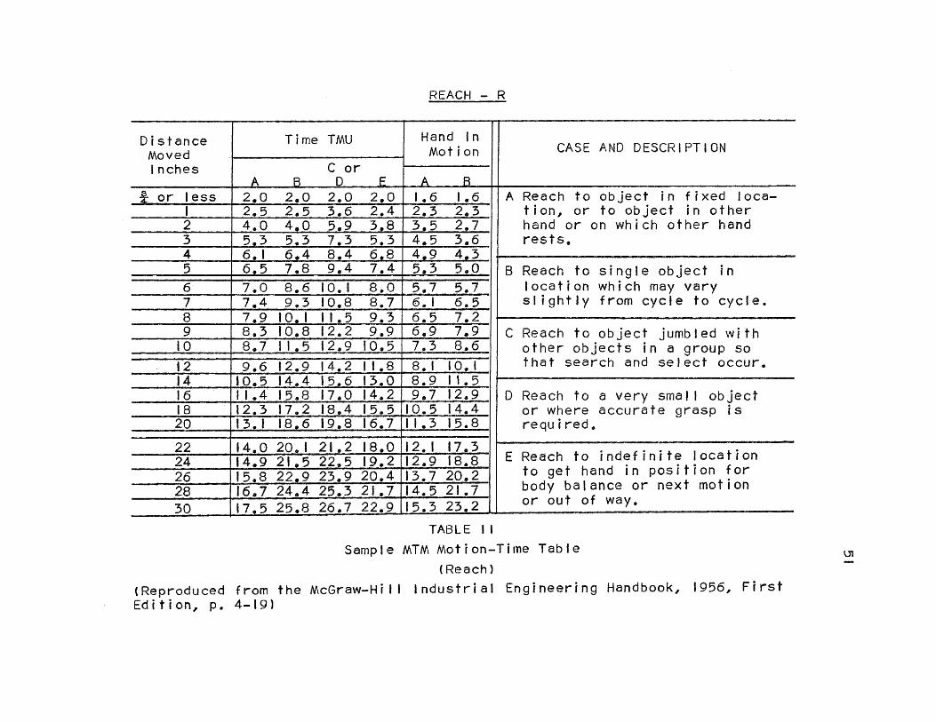
REACH - R
Distance Moved Inches
Time TMU Hand In Motion CASE AND DESCRIPTION
A B C or D E A B
or less 2.0 2.0 2.0 2.0 1.6 1.6 A Reach to object in fixed loca- tion, or to object in other hand or on which other hand rests.
1 2.5 2.5 3.6 2.4 2.3 2.3 2 4.0 4,0 5.9 3.8 3.5 2.7 3 5.3 5.3 7.3 5,3 4.5 3,6_ 4 6.1 6.4 8.4 6.8 4,9 4.3
B Reach to single object in location which may vary slightly from cycle to cycle.
5 6.5 7.8 9.4 7.4 5.3 5.0 6 7.0 8.6 10.1 8.0 5.7 5.7
7.4 9.3 10.8 8.7 6.1 6.5 8 7.9 10.1 11.5 9.3 6.5 7.2
C Reach to object jumbled with other objects in a group so that search and select occur.
9 8.3 10.8 12.2 9.9 6.9 7.9 10 8,7 11.5 12.9 10.5 7.3 8.6 12 u 9.6 12.9 14.2 11.8 8.1 0.1 14 10.5 14.4 15.6 13.0 8.9 1.5
D Reach to a very small object or where accurate grasp is required.
16 11.4 15.8 17.0 14.2 9.7 2.9 18 12.3 17.2 18.4 15.5 10.5 4.4 20 13.1 18.6 19.8 16.7 11.3 5.8
22 14,0 20.1 21.2 18.0 12.1 7.3 E Reach to indefinite location
to get hand in position for body balance or next motion or out of way.
24 14,9 21.5 22.5 19.2 12.9 8.6 26 15.8 22.9 23.9 20 4 13.7 20.2 28 16.7 24.4 25.3..21.7 14.5 21.7
30 17.5 25.8 26.7 22.9 15.3 23.2
TABLE II Sample MTM Motion-Time Table
(Reach) (Reproduced from the McGraw-Hill Industrial Engineering Handbook, 1956, First Edition, p. 4-19)
51

52
ease of application. The other tables are set up in
similar fashion, all of the variables being indexed. A
word of caution is in order at this point - one must not
try to apply MTM or any other predetermined time system
before thoroughly studying the subject. Many mistakes
will be made if the uninitiated attempts to apply data
from the time tables without being experienced in the
application of the system.
The rest of the MTM basic motions will be discussed
lightly in this paper. For a detailed description of
those motions and their application the reader may refer
to the original text by Maynard, Stegemerten and Schwab
entitled "Methods-Time Measurement", New York: McGraw-Hill
Book Co., Inc., 1948.
Move (M). "Move is the basic element employed when the predominant purpose is to transport an object to a destination.
Move time is varied in the same manner as Reach, by (1) the conditions present (2) the distance moved, and (3) whether the hand is in motion at the beginning and/or end of the move. In addition, the factor of weight or resistance has an effect on the move time."37
Turn (T). "Turn is the motion employed to turn the hand either empty or loaded by a movement that rotates the hand, wrist, and forearm about the long axis of the forearm. The length of turn is measured in degrees
37. Ibid. 8, p. 4-23.

53
turned. . The weight factor is handled by three classifications "38
Apply Pressure (AP). "Apply pressure is the basic element used to overcome resistance or to exert precise control. it appears as a distinct pause or hesitation and is required to overcome an amount of pressure or precision which is abnormal for the body member used to perform the action."39
Grasp (G). "Grasp is defined as the basic element employed when the predominant purpose is to secure sufficient control of one or more objects with the fingers or the hand to permit the performance of the next required basic element. It begins at the end of the preceding basic element and it ends when the next basic element begins."40
Five classifications exist some of which have sub-
classifications. Any complex grasps which do not fall
in any of these classifications must be analyzed through
use of other of the MTM elements.
Position (P). "The MTM element Position is defined as 'the basic element employed to align, orient, and engage an object with another object, where the motions used are so minor that they do not justify classification as other basic elements,. A position usually follows a Case C Move. There are three classes of Position. They are:
I. Class of fit 2. Symmetry 3. Ease of Handling
38. Ibid. 8, p. 4-24.
39. Ibid. 8, p. 4-24.
40, Ibid. 8, p. 4-24.

54
Since the time standard for the element Position is large, improper classification can result in serious errors in MTM analyses."41
Disengage (D). "Disengage is the basic element employed to break the contact between one object and another. It is characterized by an involuntary movement caused by the sudden ending of resistance.
There are three variables that have been found to affect the time for Disengage. These are:
I. Class of Fit 2. Ease of Handling 3. Care of Handling. "42
Release Load (RL). "Release Load is the basic element employed to relinquish control of an object by the fingers or the hand."43
In addition to the basic motions as described above,
there also exist some other miscellaneous body member
motions which are set forth as follows:
1. Walking (W - FT or W-P
2. Foot Motion (FM)
3. Leg Motion (LM)
4. Side Step (SS)
5. Turn Body (TB)
6. Bend (B)
7. Stoop (S)
8. Kneel On One Knee (KOK)
9. Kneel on Both Knees (KBK)
41. Ibid. 8, pp. 4-25 and 4-26.
42, Ibid. 8, p. 4-27.
43. Ibid. 8, p. 4-28.

55
10. Sit and Stand From A Sitting Position (SIT
and STD)
Also Eye Travel Time, Eye Focus and cranking motions
have been added since the original data was gathered.
Limiting Motions
The MTM system has developed a law called the
Principle of Limiting Motions which essentially tells
the analyst which motions can be performed simultaneously
and which cannot. This data is represented in two
dimensional chart form on the MTM Motion-Time Table.
This data is most important, because if not considered,
will frequently result in an incorrect standard time
for an operation.
The "Limiting Motion" is the one which takes the
greatest amount of time, if two or more motions are
combined, overlapped or performed simultaneously.
Combination motions are those which are performed
by the same body member at the same time. An example
would be moving a part to a location and regrasping at
the same time.
Simultaneous motions are motions performed by different
body members at the same time. The time for a right hand
motion may be greater than that for the left when the two

56
are performed simultaneously; hence the right hand motion
is the limiting motion and determines the standard time.
Simplified Data
Many times the Industrial Engineer, the Estimator
and the Tool Designer, among others, will want to quickly
determine the time to perform an operation. The MTM data
has been simplified through averaging, and the results
are claimed to have a loss of accuracy not greater than
5 per cent. Also a 15 per cent factor for personal,
fatigue and delay allowances has been included in the
data.
The tables are extremely easy to use, and the values
are so few that they may be memorized quite readily. The
major advantage of this simplification procedure is the
large savings in application time.
MTM Application Procedure
"The methods-time measurement procedure may be applied in two ways:
I. By visualizing an operation not yet existent.
2. By Observing en already established operation.
The approach to either method is similar except that the application of MTM to a visualized operation requires more attention to detail in order to avoid error. The procedure for applying MTM by either method can be divided
57
into certain basic steps these are:
Visualization
Create the operation. Visualize and organize information. Plan the operation method. Analyze operation details and
establish time.
Observation
Observe the operation. Broadly analyze and record existing
information. Record the operation method. Analyze the method and establish the
time."44
"Why is MTM Different?
MTM is the only published system that meets all four of these tests for standard data:
I. The data must be absolutely consistent at all times and under all conditions.
2. It must be possible to reproduce the data.
3. It must be possible to apply the data quickly and cheaply.
4. It must be easy for the operator to understand the data.
There are other systems which meet these tests. But, while time values have been published for other systems, basic research data have not been made available for impartial investigations and analysis. The situation could change at any time, but right now (1950) MTM stands above as the only tool of scientific management that can be proved to have met the tests."45
44. Ibid. 8, p. 4-31.
45. "How Good is MTM?", Factory Management and Maintenance, Vol. 108, August, 1950, p. 86.
OPERATION OF DIMENSIONAL MOTION TIMES (DMT)46
Definition and Theory of DMT
"DMT is a systematic procedure for analyzing elements of work in terms of motions and for measuring the work content by predetermined time values which are related to distances and other dimensional terms whenever such relationship was found to exist."46
The basic concept upon which the DMT system of
predetermined time standards is based was expressed by
Lord Kelvin in 1883 when he said:
"I often say that when you can measure what you are speaking about, and express it in numbers, you know something about it; but when you cannot measure it, when you cannot express it in numbers, your knowledge is of a meagre and unsatisfactory kind............"
The DMT system translates the meaning of the above
statement into its predetermined time standards by using
dimensions to describe the basic motions wherever possible.
"DMT is constructed on the basis of terms which are more clearly defined and specified. Common motions which recur in any operation are directly related and expressed by dimensions in inches. They refer to distance, part size, target size, and clearance. The time values designating any particular motion
46. Geppinger, H. C., DMT Dimensional Motion Times Development and Application. New York: John Wiley & Sons, Inc., 1955, P. 1.

59
are positive. Concise dimensional terms require only a small number of explanatory and defining rules, since they deal to a large extent with factual measurement."47
it is claimed that the factor of judgement had been
eliminated in other predetermined time systems as far as
effort rating was concerned, but the judgement had taken
on a new aspect in the determination of the step by step
basic motions to be used in analyzing an operation. In
other words, it was necessary to use judgement when
selecting such motions as grasping and positioning which
are generally described in terms of "easy", "difficult"
etc. The DMT approach leaves nothing to the imagination,
as it pins down and describes these motions exactly in
terms of the dimensions of the object under consideration.
It makes something specific out of a generality, and truly
maximizes the claim of all predetermined time systems that
they eliminate the factor of judgement.
"By eliminating word descriptions and the factor of judgement in the selection of a motion value, the newly developed system assumes a more scientific aspect."48
Scope of application. It is claimed that DMT can be
used for measuring all kinds of manual work, but actually
47. Geppinger, H. C., "New Motion Time Method Defined," The Iron Age, January 8, 1953, p. 106.
48, Ibid. 47, p. 106.

60
it was developed for a specific purpose, and that was to
measure processes that have been divided into specific
operations which have specific methods with no variation
whatsoever from that method. The work place of such an
operation must be fixed and permanent in its layout, and
variations in material conditions must be held to a
minimum. Hence it would appear that DMT is applicable
in a practical manner only to the repetitive assembly
operations of small parts. It must be concluded, there-
fore, that DMT is not universally applicable to all
operations, at least not in the same sense of the word,
as are the other systems of predetermined time standards.
The DMT Basic Motions
The DMT Basic Motions and Time Tables are con-
siderably more complicated in the opinion of the author
than those of any of the other systems. However, since
many of the tables are indexed by dimension only, the
application from those tables does become somewhat simpler
because of the elimination of judgement. Nevertheless,
this is more than offset by Table number one (DMT-l)
whose variables are all affected by the judgement factors
which the system is supposed to eliminate. Transports
(Reaches and Moves) require approximately the same amount
of judgement as do any of the other systems; and it is
generally agreed that these two are the more important of

61
the basic motions. Also, there is a list of no less than
41 separate miscellaneous motion times, each of which
involve judgement. Motions such as this are interspersed
throughout the five DMT motion-time tables.
Presented below in a short survey form are the DMT
basic motions as presented in the five motion-time tables:
Data sheet DMT-1. Transport Motions (T) - Corresponds
to a "reach" motion. Base Transport (B) - Corresponds to
a "move" motion. Toss Transport (T) - Applicable when
the hand does not come to a complete stop at the end of
a transport.
Transports are affected by the factors of:
1. "Restricted" (Refers to all positioning moves
not specifically covered by positioning tables)
2. "Wiping" (The rubbing of a cloth of a surface
with pressure)
3. "Brushing" (The brushing of liquids on the
surfaces of parts)
4. "Weight" (Also applies to grasping, position-
ing and release load motions)
In addition DMT-1 lists a time table for turning a
crank, 41 separate miscellaneous motion times, and 5
standardized elemental times.
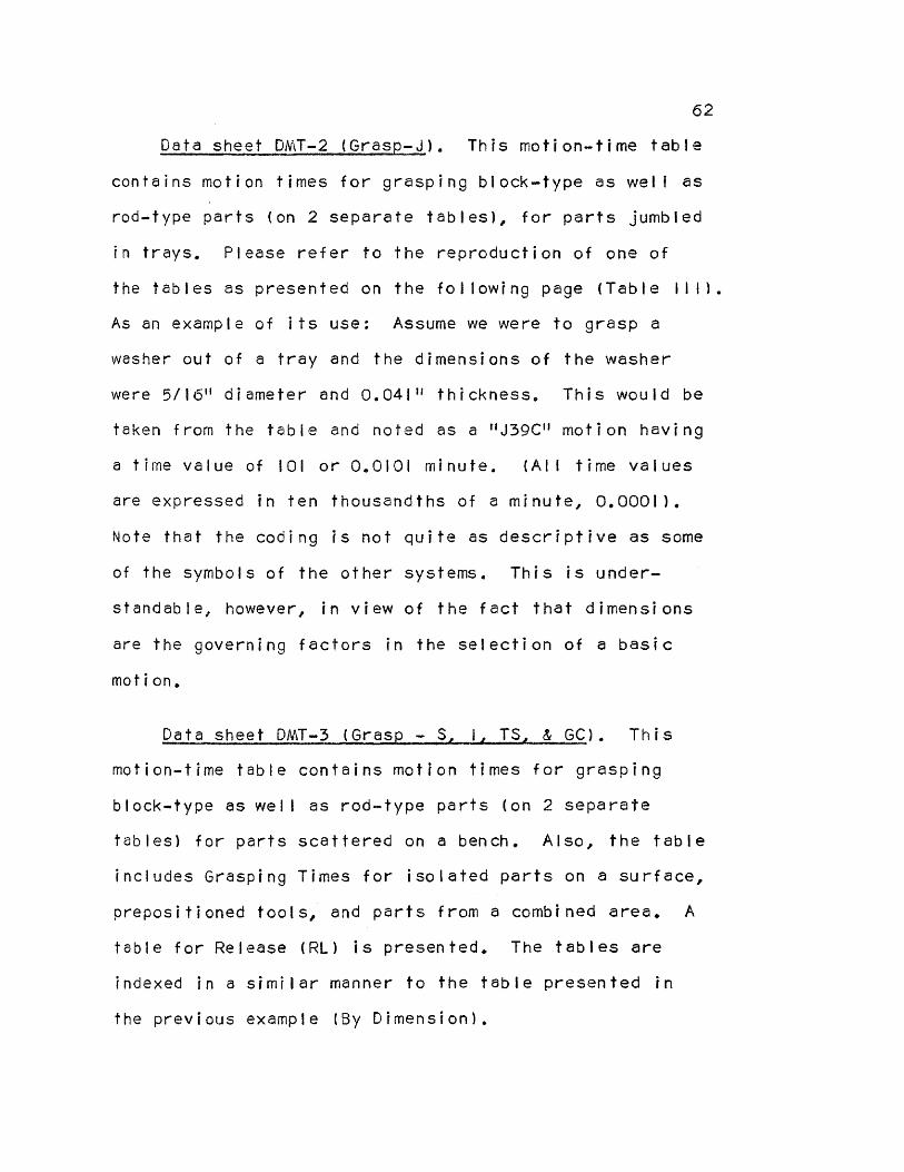
62
Data sheet DMT-2 (Grasp-J). This motion-time table
contains motion times for grasping block-type as well as
rod-type parts (on 2 separate tables), for parts jumbled
in trays. Please refer to the reproduction of one of
the tables as presented on the following page (Table 111).
As an example of its use: Assume we were to grasp a
washer out of a tray and the dimensions of the washer
were 5/16" diameter and 0.041" thickness. This would be
taken from the table and noted as a "J39C" motion having
a time value of 101 or 0.0101 minute. (All time values
are expressed in ten thousandths of a minute, 0.0001).
Note that the coding is not quite as descriptive as some
of the symbols of the other systems. This is under-
standable, however, in view of the fact that dimensions
are the governing factors in the selection of a basic
motion.
Data sheet DMT-3 (Gras - S 1 TS & GC). This
motion-time table contains motion times for grasping
block-type as well as rod-type parts (on 2 separate
tables) for parts scattered on a bench. Also, the table
includes Grasping Times for isolated parts on a surface,
prepositioned tools, and parts from a combined area. A
table for Release (RL) is presented. The tables are
indexed in a similar manner to the table presented in
the previous example (By Dimension).

GRASP-JUMBLED PARTS IN TRAYS - J
ROD TYPE PARTS
Diameter Inches
THICKNESS OR LENGTH. INCHES
Limit 0.007 0.015 0.035 0.080 0.187 0.375 0.750 1.5 3.0 6.0 40.0
Code A B C D E F G H I J
0.015 to 0.035 35 174 156 134 122 115 106 0.080 36 154 135 121 106 95 90 82 9/64 37 181 161 136 118 106 96 87 79 72 68
7/32 38 151 137 115 100 91 84 77 71 66 63 3/8 39 127 117 101 88 80 74 68 64 61 59 3/4 40 102 92 80 71 66 61 58 55 55 56
1.5 41 78 71 63 58 53 50 47 45 46 49 3.0 42 69 63 57 52 49 46 42 41 42 44 6.0 43 66 60 55 51 48 45 42 40 41 43
TABLE III
Sample Dimensional Motion Times Motion-Time Table
(Grasp)
(Reproduced from DMT Dimensional Motion Times Development and Application by H. C. Geppinger. New York: John Wiley and Sons, Inc., 1955, p. 17)
63

64
Data sheet DMT-4 (Position-P). This motion-time
table includes two positioning time tables. The first
deals with positioning a Hole to a Pin or a Pin to a
Hole. The second covers the positioning of square and
oblong Holes and Pins. Three other tables are presented
also, namely; Directional Turn (DT), Rotate, and a table
of 10 miscellaneous motions. The positioning time tables
are indexed again by dimension, the others are not.
Data sheet DMT-5 (Position-PF). This motion-time
table presents 4 separate tables. The first deals with
positioning various parts to nests. The second and third
deal, respectively, with the single or simultaneous
motions of positioning a nut to a screw or a screw to a
nut. The last has to do with positioning in a restricted
area.
The Application of DMT
In the application of the motion-time data for an
analysis of an operation, one must be quite careful that
the proper table is selected for a specific basic motion.
After that it is not too difficult to select the proper
motion by using the dimensions of the object under
consideration (only where applicable) to determine the
proper time value.
It would follow then that application of DMT data

65
requires an analyst well versed in the data and having
considerable experience in same. This definitely is not
a system for the novice; none of the PTS systems are,
but DMT even more so. Despite the claims of the author
that judgement in the selection of basic motions is all
but eliminated, a look at the 5 DMT tables in the DMT
textbook will convince anyone that this is so only in
those tables which are indexed by dimension. The others
leave a lot to be desired in the elimination of the
judgement factor.
OPERATION OF BASIC MOTION TIMESTUDY (BMT) 49
Definition and Theory of BMT
Basic Motion Timestudy is the system of predetermined
time standards that is dependent upon the definition of a
Basic Motion which states that such a motion has taken
place when and only when a body member that has been at
rest moves, and then again comes to rest. This is so
even though the rest be infinitesimal in duration. This
concept aids the analyst in describing consecutive motions
where the breakoff point between those motions might be
rather vague; such as a reach followed by a grasp.
Arbitrary terminology and vague terms have been left
49. Ibid. 8, pp. 4-91 to 4-100.

66
out of Basic Motion Timestudy. Many classifications have
been described by numbers wherever possible. This, of
course, helps the transfer of the data from one analyst
to another with no distortion.
The BMT Basic Motions
The BMT Motion-time tables have time values which are
expressed in ten-thousandths of a minute (0.0001) for ease
of application.
Reach and move (R and M). No distinction is made
between Reach and Move - they represent a hand moving
through space with no reference to purpose.
The Reach or Move essentially refers to movements of
the arms and fingers. It is here that the previously
mentioned definition of basic motion enters the picture.
Reach includes a grasp, and Move includes placing an
object. This is so only if the hand does not stop before
making the grasp etc., in which case an additional reach
or move time must be given to allow for the grasping time.
Referring to Table IV on the next page it may be
seen that Reach or Move time is dependent upon three
factors as follows:
1. Distance body member travels.
2. Degree of muscular control needed to stop the
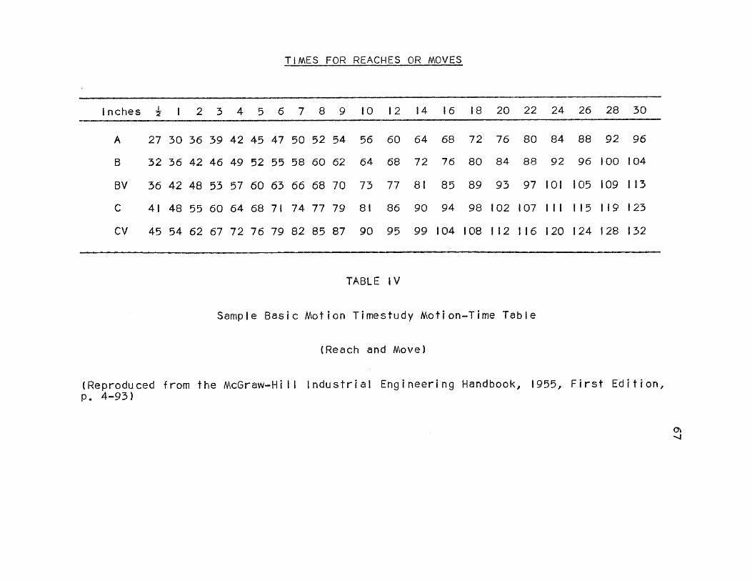
TIMES FOR REACHES OR MOVES
Inches 1/2 1 2 3 4 5 6 7 8 9 10 12 14 16 18 20 22 24 26 28 30
A 27 30 36 39 42 45 47 50 52 54 56 60 64 68 72 76 80 84 88 92 96
B 32 36 42 46 49 52 55 58 60 62 64 68 72 76 80 84 88 92 96 100 104
BV 36 42 48 53 57 60 63 66 68 70 73 77 81 85 89 93 97 101 105 109 113
C 41 48 55 60 64 68 71 74 77 79 81 86 90 94 98 102 107 III 115 119 123
CV 45 54 62 67 72 76 79 82 85 87 90 95 99 104 108 112 116 120 124 128 132
TABLE IV
Sample Basic Motion Timestudy Motion-Time Table
(Reach and Move)
(Reproduced from the McGraw-Hill Industrial Engineering Handbook, 1955, First Edition, p. 4-93)
67

68
movement. There exist three classifications here namely:
A. No muscular effort required to stop the motion.
B. The motion is stopped entirely by muscular
effort.
C. The motion is stopped by contacting a surface
usually with a grasping or placing action. The
greatest amount of control is required here.
3. The function of the eye during the motion or
Visual Direction. This depends entirely upon whether or
not the eyes move while the motion which needs eye attention
is being performed. If the end point may be watched, and
not the body member, then no time is required for Visual
Direction, This factor is used in connection with Class
B and C Motions and is designated by the letter V.
Thus it may be seen that this data, the most important
in the BMT system has easily identifiable units that are
more or less evenly spaced in time values. Referring to
Table IV on page 67 which presents the BMT Reach and Move
Data, an example of its use might be the 'following: "Reach
to a pencil 10 inches away", which would be designated by
an "RIOC" motion, having a time value of 81 or 0.0081
minute.
In addition to the above three factors the basic
motions Reach and Move are affected by two other very

important factors. These are as follows:
I. The precision factor (P). "In effect this is an extension of the B and C motions It relates to the slowing down at the end of a move while the eye directs more minute or delicate grasps or placements. The degrees of precision are described numerically by way of measured tolerances. There are five tolerance groupings ranging from 1/2 to 1/32 inch. Where the tolerance is greater than 1/2 inch, no retardation because of precision is imposed."50
This data is presented in a table whose distances
correspond to those of the Reach-Move table so that the
Precision Factor may be applied when necessary.
2. Simultaneous motions, "A complicating element in connection with Moves and Reaches is the possible retarding effect when motions are performed simultaneously. This does not always occur, and many simultaneous motions are performed without either being retarded. For instance, in driving a car one hand can steer while the other shifts gears, signals, or the like. It is only when the end points of both motions require visual direction and one hand has to wait for the eyes to direct the other to the end of the motion that added time is required.
The extent of the added time taken for this delay is governed by two obvious factors. The first is the actual distance separating the end points of the two motions, and the second is the degree of precision required to end the motions."51
50. Ibid. 8, p. 4-95.
51. Ibid. 8, p. 4-96.
69

70
The symbol for this special factor is simply listed
directly below the symbol for the Reach or Move to which
it pertains, along with the time as taken from the
Simultaneous Motion Timetable.
Eye time. "In addition to the slowing down of motions for eye fixation, there are frequent instances of actual cessation of motion while the eyes transfer focus from one point to another and when the new point of focus is different from the ending point of the arm motion that is delayed.
The allowance for this eye time is 80, to be added each time movement is stopped for eye fixation."52
Force factor. "One of the more serious retarding elements in a move occurs when it becomes necessary to overcome the effect of weight, friction, and the like. For want of a better term, this is called Force It is measured in terms of weight plus three broad, but practicable, groupings of distance. ..
The Force factor is introduced in three phases which may occur singly or combined. Arbitrary separation into these phases is introduced to simplify analysis.
1. To apply pressure when grasping an object in order to gain control of the weight. (AP)
2. After control is gained, to overcome inertia and start the weight in motion. (ST)
3. Toward the end of a motion, to apply restraining muscular effort to overcome momentum and bring the weight to a stop. (SP)
Thus when a motion consists of picking up, moving and placing an object of significant
52. Ibid. 8, p. 4-96.

71
weight, all the time phases of the Force factor are present."53, (Parenthesis added)
Turn (T). " Turn represents a specialized phase of the 'Move and Reach' motions requiring higher time values for corresponding distances because of differences in the degree of control required. "54
The Turn timetable is indexed by the number of degrees
of the turn and the classifications A, B, BV, C, and CV,
which apply in the same manner as for the Reach and Move
Timetable.
Body motions. Body motions are those performed by
the trunk or legs, and may be complementary to arm motions
or may occur as completely separate and distinct motions.
The latter case includes both motions which may be per-
formed as separate units over a range of distances, as
well as those which have no range of distance but are
performed in the same manner each time.
The BMT Body Motions together with their symbols
are as follows:
I. Foot Motion (FM)
2. Leg Motion (LM)
3. Side Step (SS)
53. Ibid. 8, pp. 4-96 to 4-97.
54. Ibid. 8, p. 4-97.
72
4. Walking (W)
5. Turn Body (TB)
6. Bend (B)
7. Stoop (S)
8. Kneel (K)
9. Arise (A)
10. Sit (SIT)
II. Stand (STAND)
Application of BMT
Concerning the application of BMT, the author of
the system puts out a few words of warning pertaining to
its limitations and use:
There do exist certain operations such as motions
which require extreme care or balance etc, that are not
covered by the 8MT Timetables. However, it is pointed
out that such motions are negligible in the total work
picture.
BMT is not a formula which may be applied by plugging
in numbers. Those who use BMT must have training, skill,
experience and imagination in its application.
SUMMARY
Chapter II was written with the intent of familiarizing
the reader with the systems of predetermined time standards,

73
so that he might have an appreciation of how they function,
and how they are applied to an industrial operation.
It was also considered important to acquaint the
reader with the thinking that preceded the conception
of each of these predetermined time systems, so that he
would acquire a basic understanding of the theory upon
which each system is based.
Again, much more detailed data as well as descrip-
tions of data, than is presented in Chapter II must be
sought if the reader is contemplating the use of any of
the mentioned systems. Training and experience are upper-
most in importance as concerns the application of such a
system, Chapter II presents but a general survey of the
operation of the most notable of the predetermined time
systems, so that the reader can better understand the
analyses as set forth in the next chapter.

CHAPTER III
THE ANALYSIS OF A SELECTED INDUSTRIAL OPERATION USING THE PREDETERMINED TIME SYSTEMS
SELECTION OF THE PREDETERMINED TIME SYSTEMS TO BE USED
IN THE ANALYSIS OF THE OPERATION, "MAKE CARTONS"
The Predetermined Time Systems that were selected for
analyzing the operation "Make Cartons" are presented in
this paper as follows:
I. Work-Factor
2. Methods-Time Measurement (MTM)
3. Basic Motion Timestudy
A first consideration was the relative popularity of
the systems. It is here that MTM and Work-Factor are
essentially keeping abreast of one another, even though
Work-Factor had better than a 10 year start on MTM. Each
system has received considerable representation in the form
of articles in the leading industrial magazines. Segur's
system of Motion-Time Analysis, though the oldest of the
systems of predetermined time standards, has received
little publicity due to the fact that his work was highly
secretive until recently. Basic Motion Timestudy and
Dimensional Motion Times have not been available long
enough to rate as much publicity as the others.
Secondly, ease of understanding the application of

75
the systems was considered, both from the standpoint of
the analyst and the people whom the study would subse-
quently affect. MTM and Work-Factor are quite straight-
forward in their operation, and the convention or symbols
used in the analysis are clearly indicative of their
meaning. Basic Motion Timestudy, in the author's opinion,
is the simplest of the systems to apply because the
variables seem to be cut to an absolute minimum. Here
too, the symbols used in the analysis are indicative of
their meaning. Motion-Time-Analysis is relatively simple
to understand, but one must write the entire operation out
in longhand as no symbols exist for the basic motions.
In addition MTA, by its author's admission is being
primarily used in the industrial scene today as a "Means
of methods control". Dimensional Motion Times is quite
complicated, as can be seen by examining the five motion-
time tables as they appear in Geppinger's text, "DMT
Dimensional Motion Times, Development and Application".
Many miscellaneous motions exist (at least 50) which
involve judgement on the part of the analyst in their
usage. It must be said, however, that the grasping and
positioning motion-time tables, among others, go a long
way in eliminating judgement since they are indexed in
the dimensions of the object only. DMT symbols, using a
dimensional coding system, are in general not too indicative,

76
as such, of the nature of the basic motion represented
by the symbol.
Lastly, it would appear that Dimensional Motion Times,
as previously discussed is not universally applicable to
all operations, in the same sense of the word, as are the
other systems of predetermined time standards. DMT is at
its most practical state of usage when it is being used
to analyze small, repetitive assembly operations having a
fixed workplace and few variations in material conditions.
In the author's opinion, Work—Factor, MTM, and BMT
are readily comprehensible, have the greatest breadth of
application, and will likely continue to be the most
popular systems of predetermined times. Thus, these will
be used in the analyses set forth on the following pages.
THE NATURE OF THE ELEMENTAL ANALYSIS
The first step in the elemental analysis of an
industrial operation was to find such an operation which
"ran the gamut" of the basic or fundamental motions so
that each would be covered in the elemental analysis, as
well as the comparative and composite analyses which
follow in the next chapter. Any operation which did not
cover most of the basic motions would be of no value to
this paper. The operation, "Make Cartons" meets this
requirement.
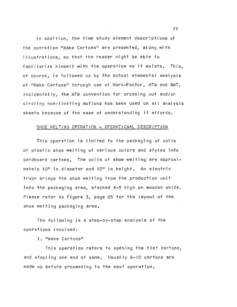
77
In addition, the time study element descriptions of
the operation "Make Cartons" are presented, along with
illustrations, so that the reader might be able to
familiarize himself with the operation as it exists. This,
of course, is followed up by the actual elemental analysis
of "Make Cartons" through use of Work-Factor, MTM and BMT.
Incidentally, the MTM convention for crossing out and/or
circling non-limiting motions has been used on all analysis
sheets because of the ease of understanding it affords.
SHOE WELTING OPERATION - OPERATIONAL DESCRIPTION
This operation is limited to the packaging of coils
of plastic shoe welting of various colors and styles into
cardboard cartons. The coils of shoe welting are approxi-
mately 10" in diameter and 10" in height. An electric
truck brings the shoe welting from the production unit
into the packaging area, stacked 4-5 high on wooden skids.
Please refer to Figure 3, page 85 for the layout of the
shoe welting packaging area.
The following is a step-by-step analysis of the
operations involved:
I. "Make Cartons"
This operation refers to opening the flat cartons,
and stapling one end of same. Usually 8-10 cartons are
made up before proceeding to the next operation.

78
2. "Line up Cartons on White Line"
After the cartons have been stapled they are lined
up at the white line as per Figure 3, page 85. The pur-
pose of doing this is to enable the operator to seal the
open ends of the cartons with the compressed air stapler
that runs overhead on a rail.
3. "Load Shoe Welting in Cartons"
It is here that the operator turns toward the skids
of shoe welting, picks up one coil and places it in the
carton, after which another is placed on top of it in the
same manner. All boxes are filled in the same way.
4. "Staple Ends of Cartons"
Next the ends of the cartons are folded over one
at a time, and sealed with the compressed air stapler
which runs on an overhead rail.
5. "Label Cartons"
In this operation the pre-glued labels are run
over a water-soaked brush to moisten and are placed on
each individual carton top.
6. "Get Skid"
The operator pulls a skid from storage and places
it in front of the sealed boxes.
7. "Load Cartons on Skid"
The operator walks toward, picks up and seta
finished carton of shoe welting on the skid. This is
repeated until all boxes are loaded.
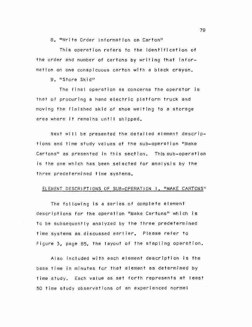
79
8. "Write Order Information on Carton"
This operation refers to the identification of
the order and number of cartons by writing that infor-
mation on one conspicuous carton with a black crayon.
9. "Store Skid"
The final operation as concerns the operator is
that of procuring a hand electric platform truck and
moving the finished skid of shoe welting to a storage
area where it remains until shipped.
Next will be presented the detailed element descrip-
tions and time study values of the sub-operation "Make
Cartons" as presented in this section. This sub-operation
is the one which has been selected for analysis by the
three predetermined time systems.
ELEMENT DESCRIPTIONS OF SUB-OPERATION 1. "MAKE CARTONS"
The following is a series of complete element
descriptions for the operation "Make Cartons" which is
to be subsequently analyzed by the three predetermined
time systems as discussed earlier. Please refer to
Figure 3, page 85, the layout of the stapling operation.
Also included with each element description is the
base time in minutes for that element as determined by
time study. Each value as set forth represents at least
50 time study observations of an experienced normal

80
operator. Leveling of the values never dropped below
90% nor above 110%. It is the opinion of the author that
said values are quite accurate.
Element 1: Pick up Carton
A. Time Study Base Time Value - .07 minutes
B. Element Description - The element begins as the
operator turns away from the completed cartons to the
right of the stapling machine and walks toward the unopened
cartons. He grasps one carton with the left hand, and the
element ends as he reaches to the carton and grasps it with
his right hand.
Element 2: Open Carton and Fold Ends
A. Time Study Base Time Value - .10 minutes
B. Element Description - Element begins as operator
moves edge of carton towards floor so he may regrasp and
gain better control. He then proceeds to open the carton
by exerting pressure on the flaps with his thumbs. After
the carton is opened, the operator sets it in front of
him, and folds the flaps down. The element ends as the
operator regrasps the carton end while holding the flaps
down.
Element 3: Place Carton on Stapler
A. Time Study Base Time Value - .06 minutes
B. Element Description - Element begins as the
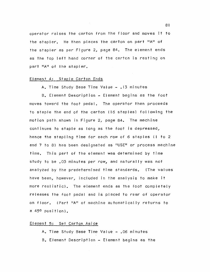
81
operator raises the carton from the floor and moves it to
the stapler. He then places the carton on part "A" of
the stapler as per Figure 2, page 84, The element ends
as the top left hand corner of the carton is resting on
part "A" of the stapler.
Element 4: Staple Carton Ends
A, Time Study Base Time Value - .13 minutes
B. Element Description - Element begins as the foot
moves toward the foot pedal. The operator then proceeds
to staple the end of the carton (16 staples) following the
motion path shown in Figure 2, page 84. The machine
continues to staple as long as the foot is depressed,
hence the stapling time for each row of 6 staples (1 to 2
and 7 to 8) has been designated as "USE" or process machine
time. This part of the element was determined by time
study to be .03 minutes per row, and naturally was not
analyzed by the predetermined time standards. (The values
have been, however, included in the analysis to make it
more realistic). The element ends as the foot completely
releases the foot pedal and is placed to rear of operator
on floor. (Part "A" of machine automatically returns to
a 450 position).
Element 5: Set Carton Aside
A. Time Study Base Time Value - .06 minutes
B. Element Description - Element begins as the

82
operator reaches to the upper left hand corner of the
carton, and turns it 90 degrees on part "A" of machine to
facilitate removal. Carton is then removed and turned
right side up as the operator turns his body and steps
toward completed cartons. Element ends as the left hand
places the completed carton on the floor.
The next step in this analysis will be the application
of MTM, Work—Factor and BMT to the elements as described
above. Please refer to the element descriptions as
presented and the illustrations, Figures I to 3, pages
83 to 85, for a clarification of the analyses as they
follow.

FIGURE I
Basic Steps in the Opening and
Subsequent Stapling of the Carton
83

84
Acme "Silver Stitcher"
Stapling Machine
FIGURE 2

85
I
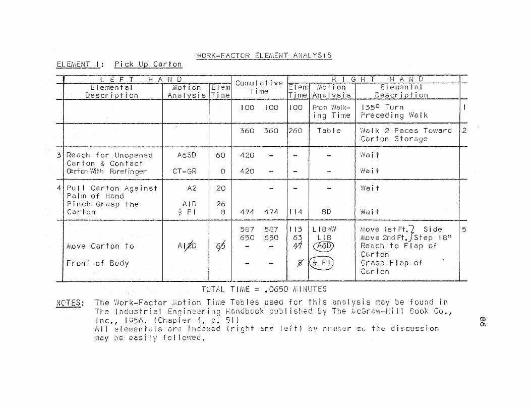
ELEMENT 1: Pick Up Carton WORK-FACTOR ELEMENT ANALYSIS
LEFT HAND Cumulative Time RIGHT HAND Elemental
Description Motion
Analysis Elem Time
Elem
Time Motion Analysis
Elemental Description
100 100 100 From Walk- ing Time
1350 Turn Preceding Walk
360 360 260 Table Walk 2 Paces Toward Carton Storage
2
3 Reach for Unopened Carton & Contact Carton Forefinger
A6SD
CT-GR
60
0
420 -
420 -
-
-
-
-
Wait
Wait
4 Pull Carton Against Palm of Hand Pinch Grasp the Carton
A2
AID 1/2 Fl
20
26 8
-
474 474
-
114
-
BD
Wait
Wait
Move Carton to
Front of Body
A12D
0
587 587 650 650
- -
-
113 63 44
L18WW L18 co
Move 1st Ft. Side Move 2nd Ft. Step 18" Reach to Flap of Carton Grasp Flap of Carton
5
TOTAL TIME = .0650 MINUTES
NOTES: The Work-Factor Motion Time Tables used for this analysis may be found in The Industrial Enginering Handbook published by The McGraw-Hill Book Co., Inc., 1956. (Chapter A, p. 51) All elementals are indexed (right and left) by number s the discussion may he easily followed,
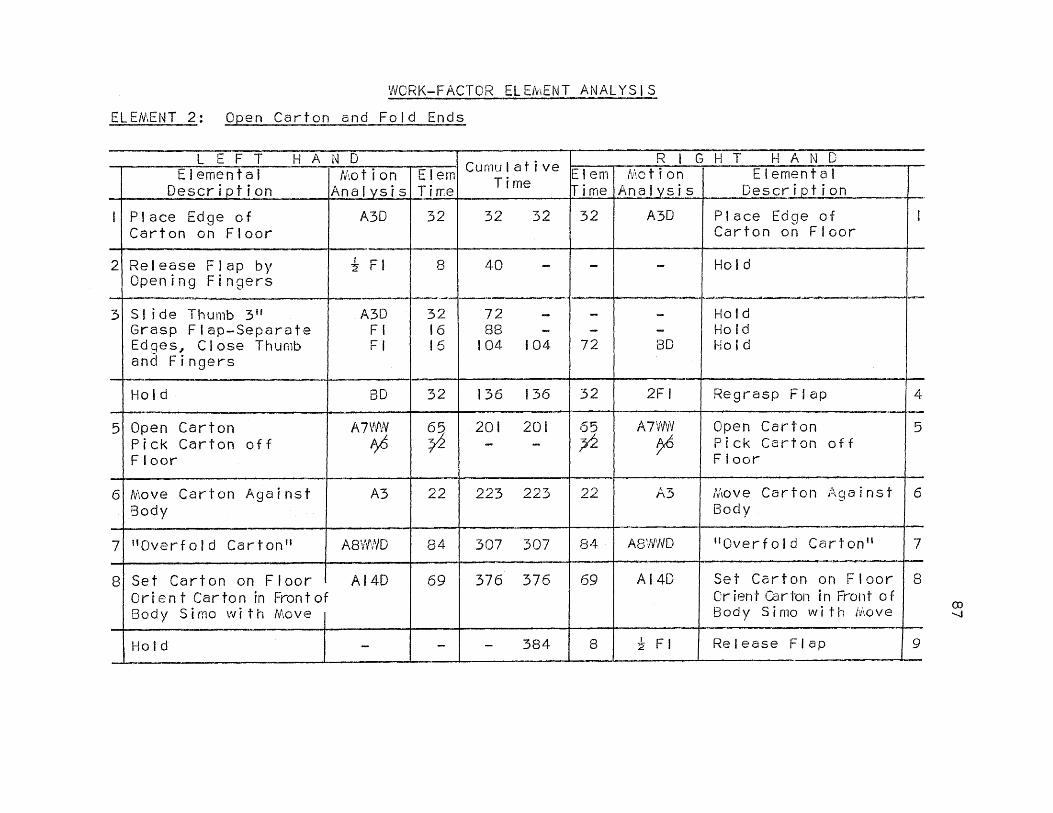
WORK-FACTOR ELEMENT ANALYSIS
ELEMENT 2: Open Carton and Fold Ends
LEFT HAND Elem Time
Cumulative Time
RIGHT HAND Elemental
Description Motion
Analysis Elem Time
Motion Analysis
Elemental Description
Place Edge of Carton on Floor
A3D 32 32 32 32 A3D Place Edge of Carton on Floor
1
2 Release Flap by Opening Fingers
1/2 Fl 8 40 - - -
Hold
3 Slide Thumb 3" Grasp Flap-Separate
Edges, Close Thumb and Fingers
A3D Fl Fl
32 16 16
72 -
88 _
104 104
- _
72
- - BD
Hold Hold Hold
Hold BD 32 136 136 32 2F1 Regrasp Flap
4
5 Open Carton Pick Carton off Floor
A7WW A6
65
0 201 201 - -
65
A7WW Open Carton Pick Carton off Floor
5
6 Move Carton Against Body
A3 22 223 223 22 A3 Move Carton Against Body
6
7 "Overfold Carton" AMID 84 307 307 84 A8WWD "Overfold Carton" 7
8 Set Carton on Floor Orient Carton in Front of Body Simo with Move
A14D 69 376 376 69
A14D
Set Carton on Floor Orient Carton in Front of Body Simo with Move
8
Hold - - 384 8 Fl Release Flap 9
87

ELEMENT 2: (Continued)
LEFT HAND Cumulative
Time
RIGHT HAND Elemental
Description Motion
Analysis Elem Time
Elem Time
Motion Analysis
Elemental Description
Hold Hold
- BD 63
- 431 439 439
47 8
A6D 2 Fl
Reach to kight Hand Flap Pinch Grasp Flap
10
I I Push Flap Down A8D 54 493 493 54 BD Hold
Reach to Left Corner Grasp Left Corner of Carton
AID F2 2.-
- 547 -
54 -
A8D Push Flap Down 12
Hold
Hold
-
BD
- 579
595 595
32
16
A3D
Fl
Slide Hand to Right Corner Grasp Right Corner of Carton
13
Hold as Pivot A3D 28 660 660 65 Al2D Twist Carton 90° 14
15 Reach to Left Flap Contact Grasp
A8 CT-GR
38 0
698 - 698 -
- -
- -
Hold Hold
16 Push Flap Down A8D 54 752 752 157 BD Hold
Hold Hold
- -
- 790 - 790
38 0
A8 CT-GR
Reach to Right Flap Contact Grasp
17
Hold BD 92 844 844 54 A8D Push Flap Down 18
19 Regrasp Carton A3D Fl
32 16 892 892
32 16
A3D Fl
Regrasp Carton 19
TOTAL TIME = .0892 MINUTES
88

WORK-FACTOR ELEMENT ANALYSIS
ELEMENT 3: Place Carton on Stapler
LEFT HAND Cumulative
Time
RIGHT HAND Elemental Description
Motion Analysis
Elem Time
Elem Time
Motion Analysis
Elemental Description
- 79 79 T8D Straighten Trunk I
Move Carton to Stapler
A5OD 1/2
196 263
- -
117 67 I22
L2OWW L 0
A OD
Move 1st Ft. Side Move 2nd Ft. Step 20" Move Carton to Stapler
2
3 Clear Part "A" A6D 47 310 310 47 A6D Clear Part "A" 3
4 Position Far Left Corner over "A"
A8SD 70 380 380 70 A8SD
Position Far Left Corner over "A"
4
5 Move Carton Gown on "A"
A26D 90 470 470 90 A26D Move Carton Down on "A"
5
6 Push Carton Till Flush on "A"
A2 20 490 490 20 BD
Hold
TOTAL TIME = .0490 MINUTES
89
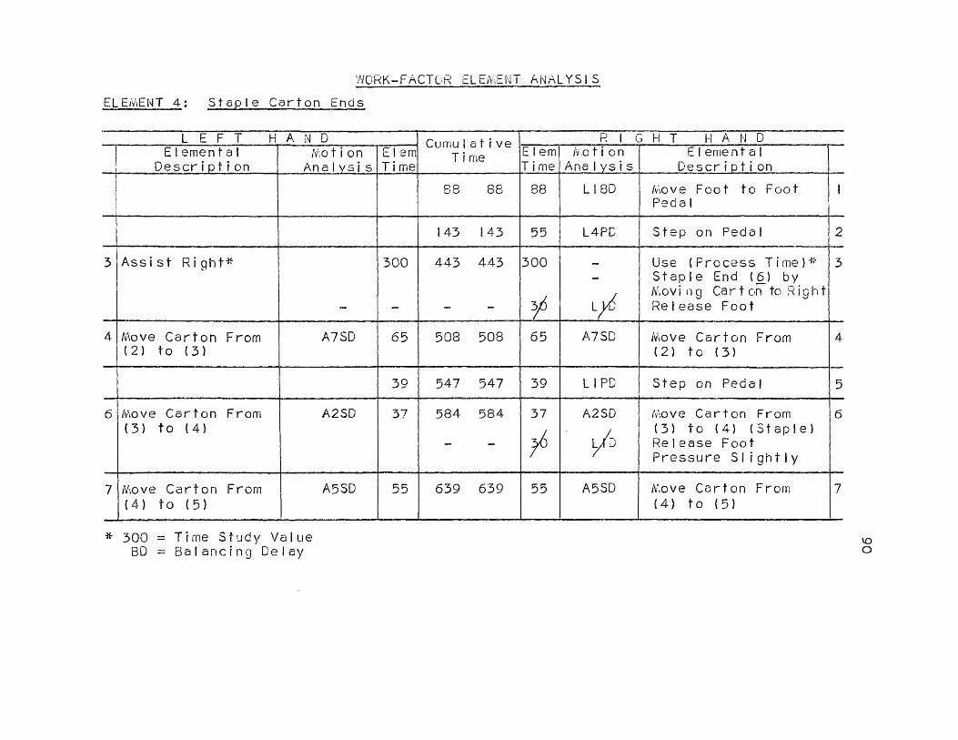
WORK-FACTOR ELEMENT ANALYSIS
ELEMENT 4: Staple Carton Ends
LEFT HAND Cumulative Time
RIGHT HAND Elemental Description Motion
Analysis Elem Time
Elem Time
fiction Anal sis
Elemental Description
88 88 88 LI8D Move Foot to Foot Pedal
I
143 143 55 L4PD Step on Pedal 2
3 Assist Right*
-
300
_
443 443
- -
300
30
- -
Use (Process Time)* Staple End (6) by Moving Cart on to Right Release Foot
3
4 Move Carton From (2) to (3)
A7SD 65 508 508 65 A7SD Move Carton From (2) to (3)
4
39 547 547 39 LIPD Step on Pedal 5
6 Move Carton From (3) to (4)
A2SD 37 584 584
- -
37 A2SD LI
D
move Carton From (3) to (4) (Staple) Release Foot Pressure Slightly
6
7 Move Carton From (4) to (5)
A5SD 55 639 639 55 A5SD Move Carton From (4) to (5)
7
* 300 = Time Study Value BD = Balancing Delay
90

ELEMENT 4: (Continued)
LEFT HAND Cumulative Time
RIGHT HAND Elemental
Description Motion
Analysis Elem
Time Elem Time
Motion Analysis
Elemental Description
39 678 678 39 LIPD Step on Pedal 8
9 Move Carton From (5) to (6)
A2SD 37
-
715 715
- -
37
30 A2SD
LA
Move Carton From (5) to (6) (Staple Release Foot Pressure Slightly
9
10 Move Carton From (6) to (7)
A6 32 747 747 32 A6 Move Carton From (6) to (7)
10
786 786 39 L1PD Step on Pedal 11
12 Use (Staple)* - 300 1086 1086 300 - Use (Staple)* 12
1174 1174 88 L18D
Replace Foot on Floor
13
* 300 = Time Study Value
TOTAL TIME = .1174 MINUTES
91

WORK-FACTOR ELEMENT ANALYSIS
ELEMENT 5: Set Carton Aside
LEFT HAND Cumulative Time
RIGHT HAND Elemental
Description Motion
Analysis Elem Time
Elem Time
Motion Analysis
Elemental Description
Reach to Corner of Carton Grasp Carton
A8D
Fl
54
16
54 -
70 70
-
70
-
BD
Wait
Wait
2
Turn Carton 90° on Pin "A"
AIOD 61 131 131 32
Regrasp Carton (Simo)
3 Pull Carton off "A" A3OD 96 227 227 96 A3OD Full Carton off "A" 3
4 Turn Carton 90° (Wrist Movement)
FS9OD, 30
292 292 55 A12D Turn Carton 90° (Arm Movement)
4
Hold Hold
- BD
- 95
- 368 387 387
76 19
A18D F3
Reach to Flap Grasp Flap (Wrap Around)
5
6 Move Arm Out From Under Carton (Controlling)
A14D 69 456 456 37 FS9OWD
Wrist Turns 90° as Carton Falls Using Flap as Pivot (Simo)
6
100
Walk Table
L24WW
135° Turn Preceding Walk Walk 1 Pace to Finished Cartons*
* See Note Next Page
92

ELEMENT 5: (Continued)
LEFT HAND HAND Cumulative
Time
RIGHT HAND Elemental Motion Elem Elem
Time Motion Analysis
Elemental Description
Wait - - 517 61 A1OD Set Carton on Floor 7
Wait BD 69 525 525 8 1/2 Fl Release Carton 8
NOTE: Turn and Walk Limited Out By Elementals 4, 5, 6, 7,
TOTAL TIME = .0525 MINUTES
93

MTV'', ELEMENT ANALYSIS
ELEMENT 1: Pick Up Carton
Description - Left Hand * Motion TMU Notion * Description - Right Hand
18.6 TBC1 ✓ Turn Away From Finished Cartons
30.0 W-2P Walk Toward Carton Storage
2
3 Reach For Unopened Carton Contact Carton With Forefinger
✓ ✓
R6D G5
10.1 0
4 Pull Carton Against Palm of Hand Regrasp the Carton
✓
✓
M3A
GIA
5,3
2.0
hove Carton to Front of Body
M1 2A 40.7 12.9 SS-C2
R6A GIB
f Side Step 18", Close to Front of Stapler Reach to Flap of Carton Grasp Flap of Carton
5
TOTAL TMU = 106.7 TOTAL TIME = .0640 MINUTES
* Limiting Motion
NOTES: The MTM Motion-Time Tables used for this analysis may be found in the Industrial Engineering Handbook published by the McGraw-Hill Book Co., Inc., 1956. (Chapter 4, pp. 19-21) All elementals are indexed (right and left) by number so the discussion may be easily followed.
94

MTM ELEMENT ANALYSIS
ELEMENT 2: Open Carton and Fold Ends
Description - Left Hand * Motion TMU Motion * Description - Right Hand
1 Place Edge of Carton on Floor
M3A 4.9
M3A Place Edge of Carton on Floor
1
2 Release Flap by Opening Fingers
RL1 2.0
3 Slide Thumb 3" Grasp Flap
R3B G2
5.3 5.6
5,6 G2 Regrasp Flap 4
5 Push Flaps Away from Body to Open Carton Pick Carton Up Off Floor Open Carton
AP-2
M6A M7A
10.6
8.1 8,g
AP-2
M6A M7A
Push Flaps Away from Body to Open Carton Pick Carton Up Off Floor Open Carton
5
6 Move Carton Against Body M3A 4.9 M3A Move Carton Against Body6
7 "Overfold Carton" mM8B AP-2
7.2 10.6 mM8B AP-2 "Overfold Carton"
8 Set Carton on Floor Orient Carton in Front of Body
M14A M3B 14.4 MI4A M3B Set Carton on Floor Orient Box in Front of Body
RL1
Release Far Flap
95

ELEMENT 2: (Continued)
Description - Left Hand Motion TMU Motion * Description - Right Hand
8.9 2.0
R6B G1A
✓ ✓
Reach to Right Hand Flap Grasp End of Flap
10
I Push Flap Down M8A 9.7
Reach to Lower Left Corner Grasp Left Corner of Carton
R1A
9.7 -
M8A Push Flap Down
12
5,3
2.0
R3A
GIA
Slide Hand Towards Upper Right Hand Corner Grasp Upper Right Corner of Carton
13
Hold as Pivot M3B 13.4 MI2B Twist Carton 90° 14
15 Reach to Flap on Left Contact Grasp
R8Am G5 6.5 0
16 Push Flap Down M8A 6.5 0
R8Am 85
Reach to Right Flap Contact Grasp
17
9,7 M8A
Push Flap Down 18
19 Regrasp Carton R3A R1A
5.3 2.5
R3A RIA
Regrasp Carton 19
* Limiting Motion TOTAL TMU = 173.2
TOTAL TIME = .1039 MINUTES 96

MTM ELEMENT ANALYSIS
ELEMENT 3: Place Carton on Stapler
Description - Left Hand Motion TMU Motion Description - Right Hand
I Straighten Trunk (See Discussion)
Move Carton to Stapler M5 B
42.9
36.4
SS-C2
M50B
Step to Front of Stapler 20" Move Carton to Stapler
2
3 Clear Part "A" M6B 8.9 M6B Clear Part "A" 3
4 Position Far Left Corner Over "A"
PISSD 14.7 P1SSD Position Far Left Corner Over "A"
4
5 Move Carton Down on "A" M26B 21.8 M26B Move Carton Down on "A" 5
6 Push Carton Till Flush on "A"
M2A 3.6
* Limiting Motion
TOTAL TMU = 91.6 TOTAL TME = .0551 MINUTES
97

MTM ELEMENT ANALYSIS
ELEMENT 4: Staple Carton Ends
Description - Left Hand * Motion TMU Motion * Description - Right Hand
21.5 LA-16 Move Foot to Fact Pedal 1
7.| LM-4 Step on Pedal 2
3 Assist Right Handx 50.0 Process Timex : Staple End (6) by Moving Carton to Right
3
4 wove Carton from (2) to (3)
M7C 11.1 M7C Move Carton from
(2) to (3) 4
7. LM-1 Step on Pedal 5
6 Move Carton from (3) to (4)
M2C 5.2 M2C Move Carton from
(3) to (4) (Staple) 6
7 Move Carton from (4) to (5)
M5C 9.2 M5C Move Carton from
(4) to (5) 7
9
M2C
7.1
5.2
LM-1 M2C
Step on Pedal B
9 Move Carton from (5) to (6)
Move Carton from (5) to (6) (Staple)
50TMU = Time Study Value 98
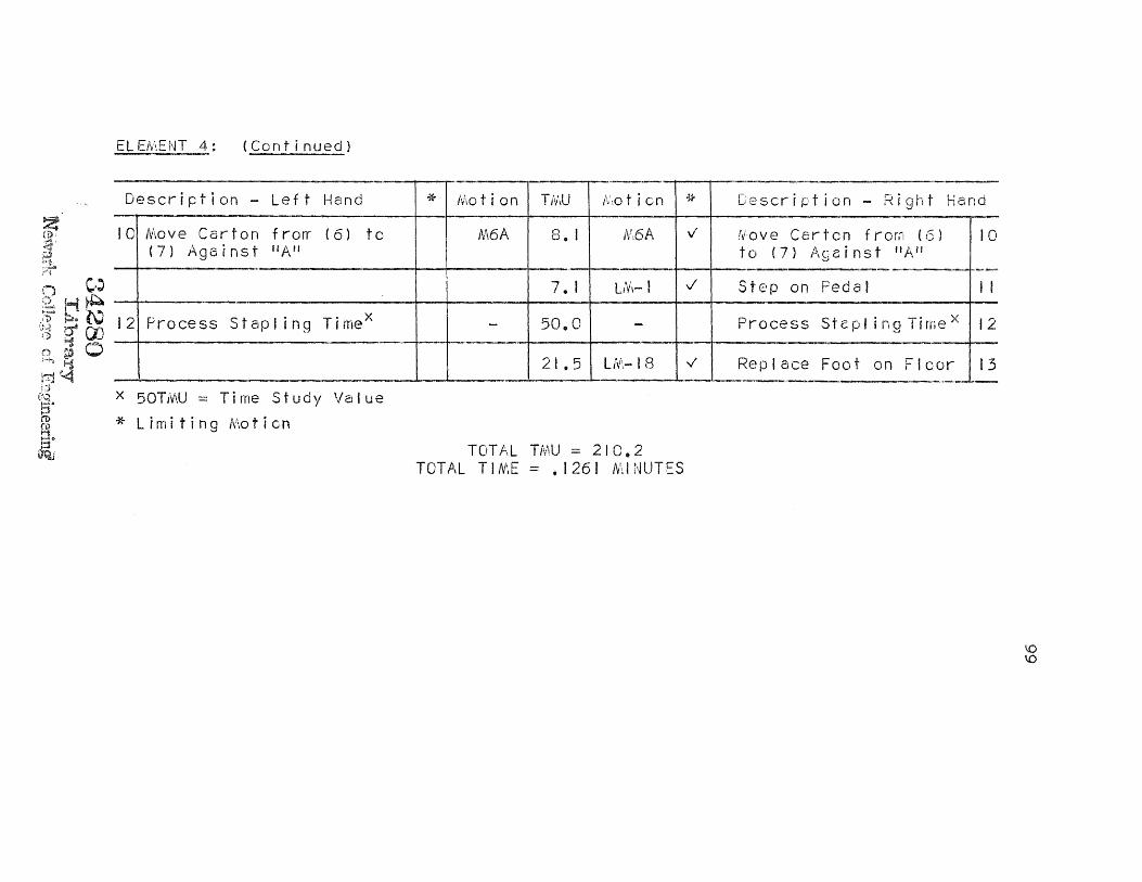
ELEMENT 4: (Continued)
Description - Left Hand Motion TMU Motion * Description - Right Hand
IC Move Carton from (5) to (7) Against "A"
M6A B°| M6A
Move Carton from (6) to (7) Against "A"
10
7. LM-1 Step on Pedal 11
1 Process Stapling Timex 50.0 - Process Stapling Time x 12
21,5 LM-18
Replace Foot on Floor 13
50TMU = Time Study Value
* Limiting Motion
TOTAL TMU = 210.2 TOTAL TIME = .1261 MINUTES
99

MTM ELEMENT ANALYSIS
ELEMENT 5: Set Carton Aside
Description - Left Hand * Motion TAW Motion * Description - Right Hand
Reach to Corner of Carton end Grasp
R8B G1A
10. 2.0
2 Turn Carton 90° on Pi n "A " M103 12,2 G2 Regrasp Carton
3 Pull Carton Off "A" M3OB 24.3 M3OB Pull Carton Off "A" 3
4 Turn Carton 90° (Wrist Movement) T90S 13.4 M12B Turn Carton 90°(Arm Movement) 4
12.3 2.0
R18A GI A
Reach to Flap Grasp Flap
5
6 Move Arm out from under Carton
4E 13.0 T90M Wrist Turns 90°as Carton Falls Using Flapas Pivot
6
18.6 15.0
TBC1 W-1P
Step to Finished Cartons
11.3 MICA Set Carton on Floor 7
2.0 RLI Release Carton 8
NOTE: Step to Finished Cartons Limited Cut By Elementals 4, 5, 6, 7.
* Limiting Motion
TOTAL TMU = 102.6 TOTAL TIME = .0616 MINUTES
100

BMT ELEMENT ANALYSIS
ELEMENT 1: Pick Up Carton
Motion Description-Left Hand * Code Motion Times Code * Motion Description-Right Hand
110 TB ✓ Turn Away from Finished Cartons
200 W-2 Walk Toward Carton Storage
Reach for Unopened Carton and Contact Grasp
R6CV 79
4 Forefinger Pull Carton ✓ M3A 39 Against Palm and Regrasp the Carton
168 SS2 ✓ Sidestep 18", Close to Front of Stapler
Move Carton to Front of M12B 71 R6C Reach to Flap of Carton Body 9 Grasp Flap of Carton
TOTAL TIME = 596 OR .0596 MINUTES
* Limiting Motion
NOTES: The BMT Motion-Time Tables used for this analysis may be found in the Industrial Engineering Handbook published by The McGraw-Hill Book Co., Inc., 1956. (Chapter 4, pp. 93-98)
All elementals are indexed (right and left) by number so that the discussion may be easily followed.
101

BMT ELEMENT ANALYSIS
ELEMENT 2: Open Carton and Fold Ends
Motion Description-LP-ft Hand * Code Motion Times
Code * Motion Description-Right Hand
I Place Edge of Carton on Floor
M3C 60
M3C ✓ Place Edge of Carton
on Floor 1
2 Release Flap by Opening R1/2B 32 Fingers
3 Slide Thumb 3" R3C 60 Grasp Flap
P1/2 6
41 RC Regrasp Flap 4
5 Push Flaps Away from AP-1 13 AR-10 Push Flaps Away from 5 Body to 0pen Carton ST-I0 13 ST-10 ✓ Body to Open Carton
/OA 50 M7A Pick Carton Up OffFloor MO
47 M6A Pick Carton Up Off Floor
6 Move Carton Against Body M3A 39 M3A ✓ Move Carton Against Body 6
7 "Overfold Carton" MBA 52 MBA •✓ "Overfold Carton" 7 AP-10 13 AR-10 ✓ ST-10 13 ST-0 VI
8 Set Carton on Floor M14C 90 M14C Set Carton on Floor 8 Orient Carton in Front of Body
M B 46 M3B
Orient Carton in Front of Body
32 RIB Release Far Flap by 9 Opening Fingers
102

ELEENT 2: (Continued)
Motion Description-Left Hand Code Motion
Times Code * Motion Description-Right Hand
71 R6C ✓ Reach to Right Hand Flap and Grasp
10
11 Push Flap Down ✓ M8A 52
Reach to Lower Left Corner and Grasp
RIC 52 MBA ✓ Push Flap Down 12
60 R3C ✓ Slide Hand to Right Corner and Grasp
13
Hold as Pivot M3B 68 M128 ✓ Twist Carton 90° 14
15 Reach to Left Flap (Contact Grasp)
✓ R8A
52
16 Push Flap Down ✓ MBA 52
52 RBA ✓ Reach to Right Flap (Contact Grasp)
17
52 MBA ✓ Push Flap Down 18
19 Regrasp Carton R4A 42 R4A v Regrasp Carton 19
* Limiting Motion
TOTAL TIME = 1,067 OR .1067 MINUTES
103

BMT ELEMENT ANALYSIS
ELEMENT 3: Place Carton on Stapler
Motion Description-Left Hand * Code Motion Times Code * Motion Description -Right Hand
Straighten Trunk (See Discussion)
1
Move Carton to Stapler MOB 176 144
SS2 M50B
✓ Step to Front of Stapler 20" Move Carton to Stapler
2
3 Clear Part "A" M6B 55 M6B Clear Part "A" 3
4 Position Far Left Corner Over "A"
M8CV 85 M8CV ✓ Position Far Left Corner Over "A"
4
5 Move Carton Down On "A"
M26B 96 M26B Move Carton Down On "A" 5
6 Push Carton Till Flush On "A"
M2A 36
* Limiting Motion
TOTAL TIME = 448 OR .0448 MINUTES
I
04

BMT ELEMENT ANALYSIS
ELEMENT 4: Staple Carton Ends
Motion * Description-Left Hand * Code Motion Times Code Motion Description-Right Hand
74 LM-18 ✓ Move Foot to Foot Pedal I
0 LM-4 ✓ Step on Pedal 2
3 AssistRight Hand x - 300 - Process Timex : Staple End (6) by Moving Carton to Right
3
4 Move Carton from (2) to (3) M7C 74 M7C ✓ Move Carton from (2) to (3) 4
50 LM-1 ✓ Step on Pedal 5
6 Move Carton from (3) to (4) M2C 55 M2C ✓ Move Carton from (3) to (4) 6
7 Move Carton from (4) to (5) M5C 68 M5C ✓ Move Carton from (4) to (5) 7
50 LM-1 ✓ Step on Pedal 8
9 Move Carton from (5) to (6) M2C 55 M2C ✓ Move Carton from (5) to (6) 9
10 Move Carton from (6) to (7) (Against "A")
M6A 47 M6A v Move Carton from (6) to (7) (Against "A")
10
50 LM-1 ✓ Step on Pedal 11
12 Process Stapling Timex - 300 - Process Stapling Timex 12
74 LM-18 ✓ Replace Foot on Floor 13
X 300 = Time Study Value * Limiting Motion
TOTAL TIME = 1,247 OR .1247 MINUTES
105

BMT ELEMENT ANALYSIS
ELEMENT 5: Set Carton Aside
Motion Description-Left Hand * Code Motion Times
Code * Motion Description-Right Hand
I Reach to Corner of Carton and Grasp
✓ R8C 77
2 Turn Carton 90° on Pin "A" ✓ M10B 64 R2 Regrasp Carton
3 Pull Carton Off "A" M30B 104 M30B Pull Carton Off "A" 3
4 Turn Carton 90° (Wrist Movement)
T90B 68 M12B ✓ Turn Carton 90°
(Arm Movement) 4
98 RISC ✓ Reach to Flap and Grasp 5
6 Move Arm Out From Under Carton
✓ M14,3 72 T90B Wrist Turns 900 as Carton Falls Using Flap as Pivot
6 SP-5
1 0 0
TB1 W-1 Step to Finished Cartons
81 M1OC Set Carton on Floor 7
32 R1/2B
✓ Release Carton by Opening Fingers
8
NOTE: Step to Finished Cartons Limited Out By Elementals 4, 5, 6, 7.
* Limiting Motion
TOTAL TIME = 596 OR .0596 MINUTES 106

107
ELEMENTAL BASE TIME VALUES (MIN), OBTAINED BY
T S T
M U E D
Y
F W A 0 C R T K 0
R
M T M
B M T
"MAKE CARTON" Listing Of Elements
Element I: Pick Up Carton
.07 .0650 .0640 .0596
Element 2: Open Carton & Fold Ends
.10 .0892 .1039 .1067
Element 3: Place Carton on Stapler
.06 .0490 .0551 .0448
Element 4: Staple Carton Ends
.13 .1174 .1261 .1247
Element 5: Set Carton Aside
.06 .0525 .0616 .0596
TOTAL TIME (MIN.) .42 .3731 .4107 .3954
TIME VALUE SUMMARY SHEET
TABLE V

108
SUMMARY
This chapter had as its basic purpose nothing more
than presenting and analyzing by predetermined time
systems the industrial operation that was selected by
reason of the fact that it pretty well "ran the gamut"
of fundamental motions as set forth by those systems.
(86% of the general fundamental motion classifications
of Work-Factor, 78% of those of MTM and 71% of those of
BMT were used in this analysis).
The description of the operation is accomplished
first through a presentation of the background of the
overall job from which the operation is taken. Next,
the operation itself is fully described by five detailed
element descriptions and the presentation of time study
values for each.
Secondly, the actual analysis of each element by
Work-Factor, MTM and BMT respectively is set forth on
the appropriate analysis sheets which bring out the
nature and time value of each of the fundamental motions
(elementals) which make up each separate element. The
predetermined time analyses as well as the element
descriptions have been supplemented by a series of three
illustrations.

109
Finally, a summary sheet of the resultant time
study and predetermined time values for the elements—in—
question are presented to conclude the chapter.
In any predetermined time system analysis of an
operation, there are always some elementals that are
controversial because of lack of exact agreement between
elemental description and work description. While the
author has exercised extreme care in the selection of the
elementals used in the analysis, he does not represent it
to be 100% accurate. He does feel, however, that were
"experts" in the several systems to make parallel analyses,
their results would not be sufficiently different to affect
the validity of the comparisons, conclusions, and
recommendations to follow.

CHAPTER IV
COMPARISON OF THE ELEMENTALS
THE NATURE OF THE ANALYSES
Chapter III set forth in very exact terms the element
analyses of the operation "Make Cartons" through the use
of three predetermined time systems. The next step
involved the determination of just exactly what was to
be compared, and how it was to be compared.
A comparison of the elements alone, or the total
cycle time alone was not enough. It was necessary to go
deeper into the problem. A comparison of the elementals
or fundamental motions, one to another, as analyzed by
Work-Factor, MTM and BMT was deemed necessary for the
purposes of this paper. In short, this essentially
amounts to a detailed comparison of the systems using
their most recent data revisions.
The next problem was to determine how to compare the
elementals. It was discovered that certain definitions
were overlapping when compared to similar definitions of
another system and as a result some elementals had to be
grouped in order to be compared. An example of this is
the BMT "reach" which is meant to include a simple grasp.
Work-Factor and MTM have separate motion analyses for
both "reach and "grasp". Hence, to compare the systems

It 1
the motions had to be grouped.
If each elemental were compared to any other, it was
found that six variations could conceivably exist as
follows:
Compare:
I. Work-Factor to MTM
2. Work-Factor to BMT
3. MTM to Work-Factor
4. MTM to BMT
5. BMT to Work-Factor
6. BMT to MTM
It may readily be seen that such an analysis would
result in a multitude of figures from which probably little
could be derived. Therefore, it was decided to arbitrarily
select one of the systems as a base and compare the other
two systems to it. The latter two systems would then, in
effect, be compared to each other also, since if two
quantities are compared to a third quantity, they are,
as a result, compared to one another. MTM was arbitrarily
chosen as the base. Using this concept, each elemental
was then compared to each other elemental of the same
motion on a percent difference basis in chart form. This
comparison is indicated on each Element Comparative Analysis
chart, pages 116 to 146 under the column entitled

112
"% Difference from Base". Incidentally, a plus (+) sign
indicates that the elemental is "looser" than the elemental
to which it is being compared, and a minus (-) sign indi-
cates that it is "tighter". Also to be included along
with the per cent difference column in comparing the
elementals, is a detailed Discussion and search of the
data as presented, in an effort to determine WHY the time
values for each individual elemental varied as the systems
were compared. Following the Discussion for each element-,
a chart follows which summarizes the findings of the dis-
cussion for that element. To go into more detail; con-
ceivably a definition for a basic motion as described by
any one of the systems may fit the situation and yet still
not compare to either of the other two definitions. In
other cases, the definition might not fit the situation
satisfactorily, but would have to be used because it is
the only analysis available in the system being used.
Other reasons for the time values being out of line with
one another might be indicated by the fact that the defini-
tions do not compare with one another even though both
seem to fit the situation; or the definitions compare but
the data does not - indicating a flaw in the original data
analysis. Also a combination of differences in both data
and definitions may be at fault. All of the foregoing is
discussed FOR EACH ELEMENTAL immediately following each

113
comparative analysis chart, and the results are summarized
in table form immediately following the Discussion. See
pages 117 to 150.
To take the Comparative Analysis one step further
as an aid in explaining why or why not the end result
(total element or cycle time) compared or did not compare,
it was necessary to find out which elementals were
responsible, and to what extent, for causing a per cent
difference in the total element times as analyzed by the
three systems. In other words, a large per cent difference
between individual elementals may have a very minor effect
on the total element or cycle time, because the time for
that element may be a very small portion or percentage
of the total time, in short a "Weighted Difference"
(column title in the Comparative Analysis) is necessary
to demonstrate the effect of the individual elemental
differences on the total element or cycle time. The
algebraic sum of the weighted per cent differences for
each elemental will result in the total per cent difference
between the final element times of the three systems.
(This same procedure may be followed for the cycle time,
and has been done in this paper on the charts entitled
"Cycle Time Weighted Per Cent Difference Analysis", pages
151 to 153). In the former chart (as well as the latter)
one may readily see by inspection which of the elementals

114
were the primary cause of the final per cent difference
in total element (or cycle) time of the three systems,
which, of course, should not exceed ± 5% (as per time
study) if the times are to be considered comparable. It
may be noted in this inspection that the weighted per
cent difference is always a great deal less than the per
cent difference from the base. This explains why even
though the individual elementals for the most part may
differ quite radically from one another, on an overall
element comparison basis, they do not. The comparison
also illustrates in graphic form how the various "tight"
and "loose" (weighted) elementals tend to cancel one
another out.
In addition the Comparative Analysis for each element
includes the number of symbols per system needed to describe
an elemental motion. Limiting motions are found in paren-
theses and limited out motions (if any) are found immediately
to the right of the latter number and separated from it by
a dash. This information may be found in the "Totals" row
and the "Motion" columns (for each system) in the Compara-
tive Analysis. From this data, the system of predetermined
times which is easiest and quickest to use may be deter-
mined (based on the operation that is being analyzed).
The time study value for each element also appears
in each comparative analysis. However the time study

115
value and the element time value as determined by a
predetermined time system cannot be directly compared,
since total cycle time is represented by the addition of
the latter element times which are set forth in ten-
thousandths of a minute. Only total cycle times can be
compared after rounding off - element times cannot be
rounded off because a great loss in accuracy would result,
as previously explained.
Finally, a composite analysis of the operation
"Make Cartons" is included in this chapter. After
acquiring a rather thorough knowledge of each system,
and a corresponding knowledge of the intricacies of the
definitions of the fundamental motions of each, the thought
of an "ideal" system using the most realistic definitions
of each entered the trend of thinking of the author. It
seemed to be an avenue well worth exploring - one which
might indeed provide a system whose time values compared
more favorably to time study values than any of those of
the other systems taken individually. These charts may
be found at the end of the chapter under the title,
"Composite Analysis", pages 154 to 156.

116
COMPARATIVE ANALYSIS
:LENENT I: PICK UP CARTON
LEMENTAL DESCRIPTION
W-F MTM BMT % DIFF. FROM BASE WEIGHTED % DIFF. MOTION* TIME MOTION TIME
4 j MOTION TIME W-F T BMT W-F BMT
Turn Away From Finished Cartons
TOTAL
135° Turn
(1)
100
100
TBCI 111.6 TB. 110
-10.4% - 1.4% - 2.0% - 0.2% (I) 111.6 (1)
110
Walk Toward
Carton Storage TOTAL
From Timetable
260 W-2P 180 W-2
(1)
200
200 +44.5% +11.1% +12.5% + 3.0% (I) 180 j (I) 260
3-L Reach For Un- opened Carton & Contact Grasp Same
TOTAL
A6SD
CT-GR
(2)
60
0
60
R6D
G5
60.6
0
R6CV (Grasp
(I)
79 Included)
79 - 1.0% +30.4% + 0.1% + 2.9% (2) 60.6
-L Pull Carton To Palm Of Hand & Regrasp Same
TOTAL
A2 AID
1/2 Fl (3)
20 26 8
54
M3A GIA
29.4 12.0
M3A
f (I)
39
39 +30.5% - 5.8% + 2.0% - 0.4% (2) 41.4
5 Side Step 18" Close To Front Of Stapler
TOTAL
LI8WW
L18
113
63
SS-C2 244.2 SS2 168
-27.8% -31.2% -10.8% -11.9% (1)-3 168 (1)-3 244.2 (2)-3 176
TOTALS
(9)-3 .0650 (7)-3 .0640 (5)-3 .0596 + 1.6% - 6.6% + 1.6% - 6.6%
TIME STUDY VALUE .07 MIN. .07 MIN .07 MIN.
No. in parenthesis = Limiting Motion Symbol(s) used in analysis.
2nd Number = Limited Out Motion Symbol(s) used in analysis.

1 1 7
Discussion: Element 1, Pick up Carton
Elemental Number Reason(s) for Variation Retween the Elementals
Work-Factor describes the Turn Body motion as
a "turn" of more than 120°. MTM and BMT as
compared to each other have essentially the
same definition as well as the same time value.
It would appear that definition in this case
is the misleading factor as far as Work-Factor
is concerned.
Walking as defined for BMT is designated as
"restricted". This is designed evidently to
cover the average condition of the workplace.
Work-Factor breaks the definition into
"restricted" or "general" walking, and MTM
defines its walking time merely as average.
The situation encountered in the "Make Cartons"
operation is not restricted, yet in the BMT
analysis we are forced to accept the one value
which includes restricted walking and which
strangely enough allows less time than Work-
Factor "general" walking. Definitions as well
* Refer to the Comparative Analysis Sheets. (Pages 116
to 146)
2

1 1 8
as time values do not agree for the three
systems.
Reaching for the carton involves an accurate
reach and a certain amount of vision since the
unopened cartons are stacked one against the
other much the same as a deck of cards. The
definitions of the motions used seem to be
essentially coincident except that the BMT
"C" reach includes time for a grasp. Here
a contact grasp is used requiring no time,
but the "C" reach does not allow for merely a
contact grasp since simple grasping time is
included. MTM and Work-Factor times compare
quite well, and BMT is out of line because of
its definition.
Each of the moves, by definition involves
moving an object against a rigid stop (using
no muscular control to stop it). The BMT
"A" reach again includes a simple grasp made
by closing the fingers. All definitions
coincide quite well. The only thing that
might be questioned is the BMT grasp for which
there exists no way of determining, exactly
what constitutes the grasp. The definition
simply states that a reach motion is intended
3
4
119
to include a "simple grasp".
The BMT and MTM definitions of sidestep
coincide, but their time values do not. The
Work-Factor definition of sidestep (single
step with both feet) is one which is synthesized
from previous data; it compares in time quite
favorably to the BMT time value. Essentially
all the definitions point to the same thing,
even though one is synthesized. It must be
concluded here that there is a flaw in the
original data, since the time values do not
compare.
5

CONDITION ELEMENTAL
TABLE VI
SUMMARY OF THE DISCUSSION - ELEMENT 1.
120
1 2 3 4 5
Definitions that fit the situation satisfactorily
ALL MTM W-F
MTM W-F
ALL ALL
All definitions similar
X X
All times similar 1
Two definitions similar X X
Two times similar X X
No definitions similar
X
No times similar X X
Probable reason for discrepancy between time values
Def. Def. Def. Data Data
1. Times must not vary from one another by more than
5% to be classed as similar.

121 COMPARATIVE ANALYSIS
ELEMENT 2: OPEN CARTON AND FOLD ENDS
:LEMENTAL DESCRIPTION W-F MTM BMT % DIFF. FROM BASE WEIGHTED % DIFF.
W-F BMT MOTION TIME W-F BMT MOTION TIME MOTION TIME
Place Ends of Carton on Floor
TOTAL
A3D
(I)
32
32
M3A
(1)
29.4
29.4
M3C
(I)
60
60
+ 8.9% +104.0%
+ 0.3% + 2.9%
2-L Release Flap By Opening Fingers
TOTAL
1/2 Fl
(I)
8
8
RL1
(1)
12.0
12.0
R1/2B (l)
32
32 -33.0% +167.0% - 0.3% + 2.0%
Slide Thumb 3" (An Arm Movement & Grasp Flap (Necessitates a Regrasp)
TOTAL
A3D
Fl
Fl (3)
32
16
16 64
R3B
G2
(2)
31.8
33.6
65.4
R3C
P
(2)
60
6
66 - 2.1%
+ 0.9% - 0.1% + 0.1%
Regrasp Flap TOTAL
2FI (I)
32 32
G2 (1)
33.6 33.6
. . .RC (1)
41 41 - 3.9% + 22.0% - 0.1% + 0.7%
Open Carton By Pushing Flap Out With Fingers
TOTAL
A7WW
(1)-1
65
65
AP-2
M-7A (2)-1
13 63.6
53 4 117.0
- AP-10 ST-10
M7A (3)-1
13
50 76
-44.4%
- 35.0% - 5.1%
- 4.1%
Move Carton Against Body
TOTAL
A3
(I)
22
22
M3A
(1)
29.4
29.4
• M3A
(1)
39
39 -25.2%
+ 32.8% - 0.7%
+ 0.9%
"Overfold" Carton Sy Pushing Flaps To Body
TOTAL
A8WWD
(1)
84
84
mM8B
AP-2 (2)
13 43.2
60.6 103.8
M8A AP-10
ST-10 (3)
52
13 78 -17.2% -23.1% - 1.8%
- 2.4%
Set Carton On Floor (Orienting of Carton Is Limited Out)
TOTAL
A14D
(1)-1
69
69
MI4A
(1)-1
86.4
86.4
MI4C
(1)-1
90
90 -20.5% + 4.2% - 1.7% + .3%
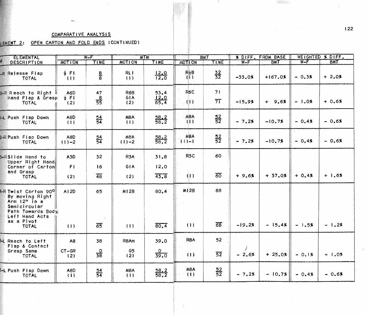
122 COMPARATIVE ANALYSIS
LEMENT 2: OPEN CARTON AND FOLD ENDS (CONTINUED)
ELEMENTAL W-F
MTM BMT % DIFF. FROM BASE WEIGHTED % DIFF. DESCRIPTION MOTION TIME MOTION TIME TIME MOTION TIME W-F BMT W-F BMT
Release Flap TOTAL
Fl (1)
8 8
RL1 12 0 R1/2B (1) j 32 32 -33.0% +167.0A - 0.3% + 2.0% (I) 12.0
o -R Reach to Right Hand Flap & Grasp
TOTAL
A6D 1/2 F1
(2)
47 8
55
R6B GIA
53.4 ,12.0
R6C
(1)
71
71 -15.9% + 9.6% - 1.0% + 0.6% (2) 65.4
M8A 58.2 MBA (I)
52 52 - 7.2$ -10.7% - 0.4% - 0.6%
1-L Push Flap Down TOTAL
A8D (1)
54 54 (1) 58.2
M8A 58.2 MBA (1)-I
52 52 - 7.2% -10.7% - 0.4% - 0.6%
2-R Push Flap Down TOTAL
A8D (1)-2
54 54 (1)-2 58.2
3-R Slide Hand to Upper Right Hand Corner of Carton and Grasp
TOTAL
A3D
Fl
(2)
32
16
48
R3A
G1A
31.8
12.0
R3C
(I)
60
60
+ 9.6% + 37.0% + 0.4% + 1.6% (2) 43.8
4-R Twist Carton 900 By Moving Right Arm 12" in a Semicircular Path Towards Body, Left Hand Acts as a Pivot
TOTAL
AI2D
(I)
65
65
M128 80.4 M128
(I)
68
68 -19.2$ - 15.4% - i.5% - 1.2% (1) 80.4
R8Am
G5
39.0
0
R8A
(1)
52
52 - 2.6% + 25.0$ - 0.1% + 1.0%
Reach to Left Flap & Contact Grasp Same
TOTAL
A8
CT-GR (2)
38
0 38 (2) 39.0
MBA 58.2 M8A 52 (1) 52 - 7.2% - 10.7% - 0.4% - 0.6%
5-LPush Flap Down TOTAL
A8D (I)
54 54 (1) 58.2

123 COMPARATIVE ANALYSIS
ELEMENT 2: OPEN CARTON AND FOLD ENDS (CONTINUED)
ELEMENTAL DESCRIPTION
W-F T MTM BMT % DIFF. FROM BASE WEIGHTED % DIFF. MOTION TIME MOTION TIME MOTION TIME 1 W-F BMT W-F BMT
17-R Reach to Right Flap & Contact Grasp Same
A8
CT-GR
38
0
R8Am
65
39.0
0
R8A 52
39.0
18-R Push Flap Down TOTAL
A8D (I)
54 M8A (I)
58.2 MBA (1)
52 - 7.2% - 10.7% - 0.4% - 0.6% 54 58.2 52
19 Regrasp Carton By Moving Arm 3" & Fingers 1"
TOTAL
A3D
Fl (2)
32
16
R3A
RIA (2)
31.8
15.0
R4A
(I)
42
+ 2.6% - 10.2% + 0.1% - 0.5% 48 46.8 42
TOTALS (26)-4 .0892=.0892 MIN. (27)-4 .1039 MIN. - (24)3
.1067 MIN= N. .1067 -14.1% + 2.7% -14.1% + 2.7%
TIME STUDY VALUE .10 MIN. .10 MIN.
.10 MIN.

124
Discussion: Element 2, Open Carton and Fold Ends
Elemental Number Reason(s) for Variation Between the Elementals
Here the definitions vary widely. Work-Factor
states that the "Definite Stop" factor must be
included for any motion that refers to placing
an object. MTM "Move Case A" infers that we
are moving an object against a stop (the floor)
with little sight or concentration. The com-
parable Work-Factor motion would not include
"Definite Stop" by definition and if this were
used it would vary from the MTM value by 24%
and the BMT value by 44%. The BMT "C Move"
fits in here because as defined, it refers to
the placing of an object. Hence it may be
seen that two definitions (Work-Factor and BMT)
coincide, but their times do not. None of the
times are within the ± 5% range.
The MTM and Work-Factor Definitions both amount
to the same thing for a release of this type,
namely; a simple opening of the fingers. The
times do not agree. The BMT definition of a
release left much to be desired as essentially
it had to be classed as a "B" finger reach
since the opening of the fingers is stopped by
2

125
"muscular control" as per the definition. The
BMT "reach" includes a grasp. How can a
release include a grasp? The analysis is
contradictory but the BMT "reach" had to be
used since that was all that was available.
The Work-Factor and BMT "reach" motion
definitions coincide perfectly. However,
the BMT value includes a simple grasping time
to which must be added the "Precision Factor"
value to compensate for the regrasp or second
grasp. The 2 Fl motions in Work-Factor repre-
sent a "regrasp" by 2 movements of the fingers
(a synthesized definition). The MTM definition
for the reach does not agree with the other two
in so many words, and the same applies to the
regrasp, but essentially they all point in the
same direction. All time values coincide
within the accepted range.
The MTM and Work-Factor definition of a regrasp
both seem to include two simple movements of
the finger and the respective times compare
quite well. The BMT "grasp" is difficult to
put together since the "C" reach must be used
because it applies to touching an object at
the end point of the reach. The definition
3
4

126
hardly compares with the other two as the BMT
"Reach and Move" table definitions seem to
apply primarily to the arms. The time value is
far out of line.
The opening of the flaps is a difficult thing
to analyze. Lack of precise measurement caused
the Analyst to assume pushing against a resis-
tance of 10 pounds for all systems while moving
the arms seven inches. The Work-Factor definition
included just exactly that - a movement of the
arm seven inches against a pressure of 10 pounds.
The BMT application of pressure is divided into
first gaining contro1 of the object and then
applying a pressure to start the motion. The
MTM "Apply Pressure" must be utilized in this
motion along with the move. The difference in
times is due mainly to the fact that the Work-
Factor arm motion includes a continuing pressure
through the move, whereas the other two have
somewhat of an overlap between the apply
pressure and the move. In the latter two cases
the full move time should not be given since
some of it takes place during the apply pressure,
but it is not known how much. The MTM and BMT
definitions are unsatisfactory for this reason
5

127
and the times allowed are therefore excessive.
The Work-Factor definition appears to be entirely
satisfactory.
All of the definitions here indicate quite
clearly that an object is moved against a stop
(the body) without being stopped by muscular
effort. They coincide perfectly. All of the
time values, however, are out of line.
Here the comments of "Elemental 5." apply,
but in reverse. There is no continuing
pressure, therefore the Work-Factor definition
does not apply, but must be used since it is
the only one available. The MTM and BMT
definitions fit much better here because the
move is followed by en apply pressure. Another
factor, namely; hand in motion from the previous
elemental enters into the MTM definition. This
is not considered in either of the other two
definitions. Basically the MTM and BMT
definitions are similar but the times compare
quite poorly. Strangely enough the time values
are much closer for the MTM and Work-Factor
motions, even though the definitions do not
coincide.
6
7

128
Same comments as "Elemental I."
Same comments as "Elemental 2."
The definitions all concur quite closely (the
reaching portion only). The BMT reach includes
a "simple grasp", as it is called, but there
really is no way of analyzing that grasp to
compare it to the others.
Basically this movement involves moving the
flap down against a stop (the rest of the
carton). It was the author's opinion that a
"Definite Stop" control factor should be
included in the Work-Factor Definition,
because the hand does come to a stop before
the next motion can begin, even though no
muscular control is employed to make the stop.
This may be stretching the definition a little,
but thus enters the element of judgement on
the part of the Analyst. The MTM and BMT
definitions of movement against a stop apply
perfectly. The times are just out of the
± 5% range.
Same comments as "Elemental 11."
The "reach" portion of the motions have similar
8
9
10
11
12
13

129
definitions. However, the grasp must be further
analyzed in that it involves more than a "1/2 Fl"
for Work-Factor, since the fingers move at
least an inch. The MTM "GIA" grasp is the only
one which applies, even though it does not fit
the situation exactly. The so-called "simple
grasp" is included in the BMT value, but there
is no way of knowing what the time is for
the grasp, nor exactly what type it is. The
definitions cannot be comparable because as may
be seen the Work-Factor grasp is more than the
simple "pinch" grasp. The inclusion of "grasp"
in the BMT definition makes it essentially non-
comparable to the other two.
All of the definitions here fit the case in
their own way. The Work-Factor and BMT defini-
tions are the same in that a definite stop is
indicated at the end of the movement. The
MTM move evidently presumes a stop since the
object is moved to an approximate location, but
it does not come right out and state that fact.
It is concluded that the definitions all are
quite applicable to this type of move. The
Work-Factor and BMT times are comparable; MTM
is out of line which might be due to the slight
14

130
difference in definition.
This type of motion is one which does not
involve a factor of definite stop at the end of
the motion. A contact grasp is made when the
hand touches the flap. The Work-Factor and
MTM definitions for this type of reach fit the
situation quite well since no stop is made (no
control required by operator) for the Work-
Factor definition, and for the MTM the hand is
in motion at the end of a reach to "an object
on which the other hand rests". The contact
grasp is, of course, zero. BMT is again out
of line because the time value includes a
simple grasp.
Same comments as "Elemental 11."
Same comments as "Elemental 15."
Same comments as "Elemental II."
This regrasp involves a movement of the arm a
distance of three inches and a subsequent closing
of the fingers a distance of one inch. All
motions here were analyzed satisfactorily by the
three systems. The definitions coincide quite
well, except that there exists the problem of
15
16
17
18
19

the exact nature of the grasp in the BMT
"reach"® The grasp cannot be analyzed - it
is there as a set figure and nothing can be
done about it.
131

CONDITION
TABLE VII
SUMMARY OF THE DISCUSSION - ELEMENT 2.
ELEMENTAL
1 2 3 4 5 6 7 8 9 10 11 12 13 14 15 16 17 18
19
Def. that fit the situation satisfactorily
ALL W-F MTM
ALL ALL W-F ALL MTM W-F
ALL
W-F MTM
ALL ALL ALL MTM W-F
ALL
MTM W-F
ALL MTM W-F
ALL
ALL
All definitions similar X X
All times similar 1
X
Two definitions similar
X X X X x x x x x x X x x x x x x
Two times similar X
X
X
X
x x X
x x x
No definitions similar
•
No times similar X X X X X
X X X
Probable reason for discrepancy between time values
I. Times must not vary from one -another by more than ± 5 to be classed as similar. * Times here compare for the two definitions that are not similar.
DEF.
& DA
TA
DEF.
& DA
TA *
DEF
.
DEF.
& DA
TA *
DEF.
DEF.
DEF.
& D
ATA
DEF.
& D
ATA
* D
EF.
& DA
TA
* DEF.
& D
ATA
DEF.
& DATA DEF.
& D
ATA
* D
EF.
& DATA
DATA
DEF.
& DATA
DEF.
DEF.
& DATA D
EF.
& DATA
132

COMPARATIVE ANALYSIS 133
EMENT 3: PLACE CARTON ON STAPLER
ELEMENTAL DESCRIPTION
W-F MTM BMT % DIFF. FROM BASE WEIGHTED % DIFF. MOTION TIME MOTION TIME MOTION TIME W-F A BMT W-F BMT
Straighten Back (Trunk Motion)
TOTAL
T8D
(I)
79
79 NO ANALYSIS NO ANALYSIS
L
INFINITY 0.0% +13.9% 0.0%
Step to Front of Stapler by Side-stepping 20" (Move Carton Limited Out)
TOTAL
L20WW
L20
(2)-I .
117
67
184
SS-C2
(1)-I
257.4
257.4
SS2
(1)-1
176
176 -28.6% -31.6% -13.3% -14.7%
Clear Part "A" TOTAL
A6D (1)
47 47
M6B (1)
53g4 53.4
M6B (1)
55 55 -12.0$ + 2.9% - 1.2% + 0.3%
Position Far Lef Corner Over "A"
TOTAL
A8SD
(1)
70
70
P1SSD
(1)
88.2
88.2
M8CV
(1)
85
85 -20.6% - 3.6% - 3.2% - 0.6%
Move Carton Down on Part "A" of Stapler
TOTAL
A26D
(1)
90
90
M266
(1)
130.8
130.8
M268
(1)
96
96 -29.6% -26.6% - 7.0% - 6.3%
Push Carton
Part "A" TOTAL
A2
(I)
20
20
M2A
(I)
Flush Against 21.6
21.6 k
M2A
(1)
36
36 - 7.4% +66.4% - 0.3% + 2.6%
TOTALS (7)-I 490= .0490 (5)-
551.4= .0551
(5)- 448= .0448
-11.1% -18.7% -11.1% -18.7$
TIME STUDY VALUE .06 .06 .06

134
Discussion: Element 3, Place Carton on Stapler
Elemental Number Reason(s) for Variation Between the Elementals
1 Before the sidestep can begin, the trunk of
the body must be brought up (straightened).
Work-Factor takes care of this very nicely.
MTM and BMT have NO analysis for such a trunk
movement. Perhaps it is meant to be included
in a sidestep, but this is not expressly
stated, so it must be assumed that the data as
well as the definitions are non-existent for
this type of trunk motion in the latter two
systems.
2 The motion being described here is not terminated
until the left leg comes to rest beside the
right leg. (Next motion cannot begin) All
of the definitions state this, The BMT and
MTM definitions for sidestep coincide, whereas
the Work-Factor definition is slightly different,
having been (synthetically) built up from two
leg motions. However, it does essentially say
the same thing as the other two definitions,
but in other words. The Work-Factor and BMT
values compare quite favorably; the MTM value
is far out of line.

135
This motion has to do with merely moving the
carton past part "A" so that the positioning
of the carton over that part can begin. All
of the definitions agree here in that movement
to an approximate location is implied.
Neither Work-Factor nor BMT has a specific
definition for this positioning. The move-
ment itself must be analyzed and built up from
the general definitions of motions of the two
systems. The Work-Factor arm movement was
selected as the positioning movement and the
factor of "Steering" was included since the
motion was directed at and through the target.
The BMT definition also must be built up and
the only logical choice here was the class "C"
move, or the most accurate move. The "Visual
Direction" Factor was added since the eyes
must be directed at the target in this case.
The MTM "positioning" elemental seems to fit
the situation very nicely. It is a case I
position since no pressure is applied; semi-
semetrical because it can go over part "A" in
several ways; and "D" because the length of
the carton makes it difficult to handle (the
hands grasp the carton quite a bit from the
3
4

136
point of contact, and it is in general quite
awkward to handle. It would appear that the
latter definition of the motion is the best for
the situation, as three variables are considered;
whereas BMT and Work-Factor consider only two
and one, respectively. The definitions do not
compare, but they are applicable to the
situation. This elemental is another case of
taking the only definitions available to analyze
the situation-in-question.
This motion at first glance would appear as if
a movement against a stop were involved. This
is not so since the carton is moved down on
part "A" in such a manner that a certain
amount of muscular control is used to stop
the motion. The definitions then compare quite
favorably. The MTM time value is the largest
of the three.
All definitions compare almost exactly for the
movement of the carton against part "A" of the
stapler, which acts as a stop. The motion is
stopped with no muscular effort, hence all
three definitions coincide very nicely. This
is one of the few instances where all definitions
fit the situation as well as coinciding with one
another.
5
6

137
TABLE VIII
SUMMARY OF THE DISCUSSION - ELEMENT 3.
CONDITION ELEMENTAL
1 2 3 4 5
6
Definitions that fit the situation satisfactorily
W-F ALL ALL ALL ALL ALL
All definitions similar X X X X
All times similar 1
Two definitions similar
Two times similar
X X
No definitions similar
X X
No times similar X
X
X X
Probable reason for discrepancy between time values
DEF. &
DATA DATA DATA
DEF. &
DATA DATA DATA
1. Times must not vary from one another by more than
5% to be classed as similar.

1 138
COMPARATIVE ANALYSIS
ELEMENT 4: STAPLE CARTON ENDS
ELEMENTAL DESCRIPTION
W-F MTM BMT I % DIFF. FROM BASE WEIGHTED % DIFF. MOTION TIME MOTION TIME MOTION TIME W-F BMT W-F BMT
Move Foot to Foot peda1 18"
TOTAL
L18D
(I)
88
88
LM-18
(I)
129.0
129.0
LMI8
(1)
74
74 -31.8% -41.8% -3.2% -4.4%
Step on Pedal (Foot Hinged at Ankle)(Pressure Less Than 10 lbs.)
TOTAL
L4PD
(1)-1
55
55
LM-4
(I)
42.6
42.6
LM-4
(1)
50
50 +29.0% +17.3% +TI.0% +0.6%
Process Stapling Time
- 300 - 300.0 - 300 - - - -
Move Carton From (2) to (3) (Position)
TOTAL
A7SD
(I)
65
65
M7C
(1)
66.6
66.6
M7C
(I)
74
74 - 2.4% +11.1% -0.1% +0.6%
Step on Pedal TOTAL
LIPD (1)-1
39 39
LM-1 (I)
42.6 42.6 LM-1
(1) 50 50 - 8.4% +17.3% -0.3% +0.6%
Move Carton From (3) to (4) (2 Staples)
TOTAL
A2SD
(1)-1
37
37
M2C
(I)
31.2
31.2
M2C
(1)
55
55 +18.5% +76.2% +0.5% +1.9%
Move Carton From (4) to (5) (Position)
TOTAL
A5SD
(I)
55
55
M5C
(I)
55.2
55.2
M5C
(I)
68
68 0.0% +23.2% 0.0% +1.0%
Step on Pedal TOTAL
LIPD (TI)
39 39
LM-1 (I)
42.6 42.6
j LM-1 (I)
50 50 - 8.4% +17.3% -0.3% +0.6%

139
COMPARATIVE ANALYSIS
ELEMENT 4: STAPLE CARTON ENDS (CONTINUED)
ELEMENTAL DESCRIPTION
W-F MTM ;MT % DIFF. FROM BASE WEIGHTED % DIFF. BMT MOTION TIME MOTION TIME I MOTION TIME W-F BMT I W-F
Move Carton From (5) to (6) (2 Staples)
TOTAL
A2SD
(1)-1
37 M2C
(I)
31.2 M2C
(I)
55
+18.5% +76.2% +0.5% +1.9% 37 31.2 55
Move Carton From (6) to (7)
TOTAL
A6
(1)
32 M6A
(I)
48.6
M6A
1 (I)
47
-34.2% - 3.3% -1.3% -0.1% 32 48.6 47
Step on Pedal TOTAL
LIPD (1)
39 LM-1 (1)
42.6 LM-I (I)
50 50 8.4% +17.3% -0.3% +0.6% 39 42.6
Process Stapling Time
- 300 - 300.0 300 - - - - -
Replace Foot on Floor
TOTAL
L18D
(1)
88
88
LM-18
(1)
I 129,0 LM-18
(I)
74
-31.8% -41.8% -3.2% -4.4% 129.0 74
TOTALS (11)-4 1174= .1174 MIN. (11) 1261.2=
.1261 MIN (II) 1247=
. 1247 MIN. - 6.8% -1.1% -6.8% -1.1%
TIME STUDY VALUE .13 .13 .13 1

Discussion: Element 4, Staple Carton Ends
140
Reason(s) for Variation Between the Elementats
The MTM and BMT definitions for a leg motion
coincide perfectly in that both allow for a
leg motion hinged at either the hip or the
<nee. The Work-Factor definition, however, is
nuch better in that it is more specific. The
former two definitions are very general in
nature whereas the Work-Factor leg motion in
his case includes the Factor of "Definite
Stop" which does take place immediately before
'he short leg motion that pushes the pedal
down. None of the times coincide, so it would
appear that the definitions as well as the
late for MTM and BMT are out of line. The
atter two definitions leave much to be desired
)ecause they are far too general in nature.
The foot pedal in this case is similar tb the
dutch on an automobile in its operation, but
in reverse. The operator, when stapling,
pushes the pedal down just a little below the
point at which it will staple so that a slight
release of pressure will stop the stapling
action. Hence on the push downward he is
exercising caution to move it just so far, and
Elemental Number
TI
2

141
then a definite stop follows. This is well
defined by the Work-Factor leg motion with the
"Precaution" and "Definite Stop" Work-Factors
added in. The MTM and BMT definitions are very
poor, again because they are too general. They
do not consider the care and stop as does the
Work-Factor definition. Also, they consider
an average distance which contradicts the
theory upon which the systems are based.
It might be noted that when the foot
releases the pedal, that this occurs just
before the last staple hits. In other words,
the operator intuitively knows that the machine
will follow through with one more staple after
he releases the pressure on the pedal at the
proper point. Therefore, the movement of the
carton to the next stapling position can take
place immediately after the last staple has
hit. This lowers the next leg motion to a
distance of one inch which cuts the time value
down considerably. However, the MTM and BMT
values do not change since they are designated
as applying to any leg motion of up to 6".
This is far too general to make the latter
definitions of any real value on a scientific

142
basis. The release of pressure by the foot is
limited out by the stapling time as previously
explained, (the motion is limited out near the
end of the stapling) but even so there exists
no MTM or BMT definition which could fit the
situation unless the LM motion be used, and
that would be ridiculous, since too much time
would be allowed for the motion. Therefore,
it is not shown on the BMT and MTM Analysis
Sheets because of this, and also because the
motion is limited out anyway.
Process Stapling time is the time required for
the machine to staple the carton 6 times as
the operator moves it to the right. This
cannot be analyzed by any predetermined time
system.
This motion implies movement of the carton
to an exact location so the stapling process
may begin. All the definitions fill this
qualification quite well. They fit the
situation even though they are not exactly
comparable to each other. Again the BMT Move
data seems to be loose compared to the other
two. This type of motion fits the need not
only for the positioning move prior to stapling,
3
4
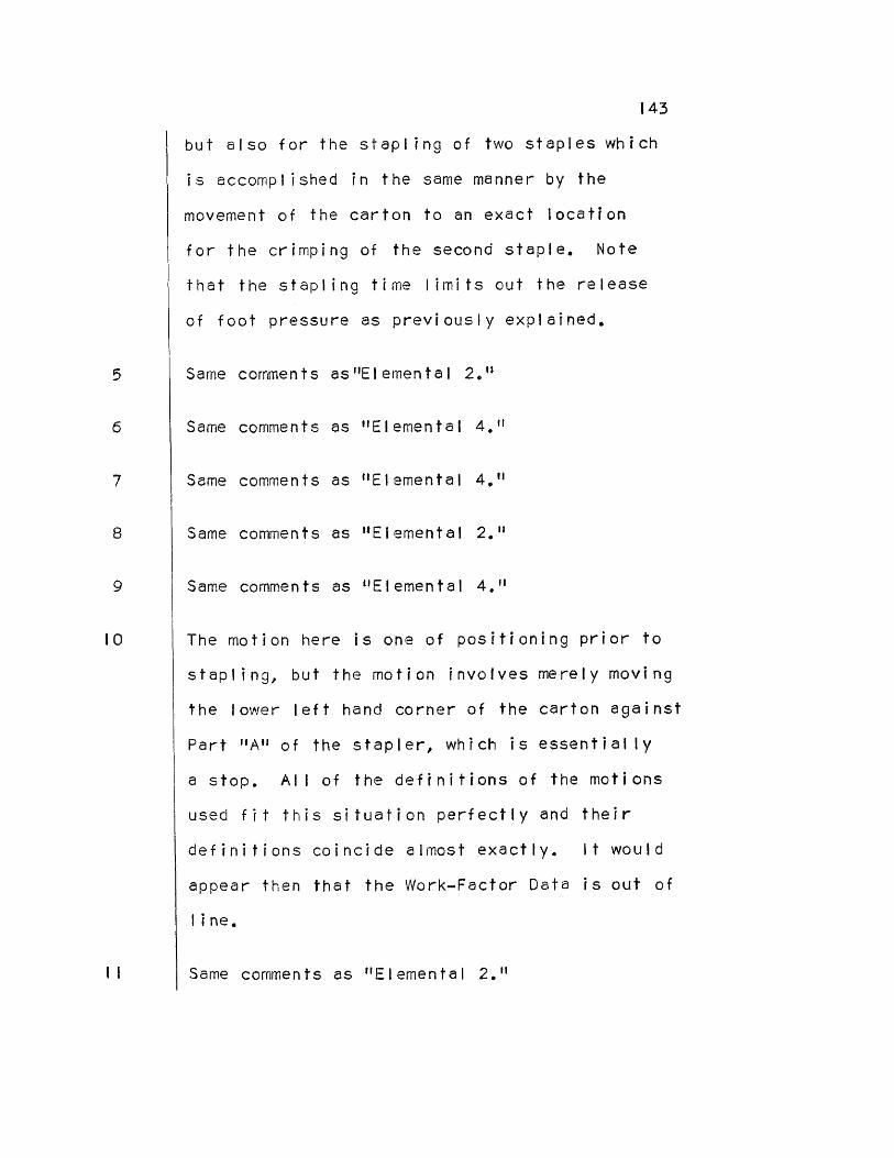
5
6
7
8
9
10
II
143
but also for the stapling of two staples which
is accomplished in the same manner by the
movement of the carton to an exact location
for the crimping of the second staple. Note
that the stapling time limits out the release
of foot pressure as previously explained.
Same comments as"Elemental 2."
Same comments as "Elemental 4."
Same comments as "Elemental 4."
Same comments as "Elemental 2."
Same comments as "Elemental 4."
The motion here is one of positioning prior to
stapling, but the motion involves merely moving
the lower left hand corner of the carton against
Part "A" of the stapler, which is essentially
a stop. All of the definitions of the motions
used fit this situation perfectly and their
definitions coincide almost exactly. It would
appear then that the Work-Factor Data is out of
line.
Same comments as "Elemental 2."
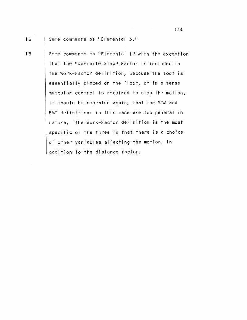
144
Same comments as "Elemental 3."
Same comments as "Elemental I" with the exception
that the "Definite Stop" Factor is included in
the Work-Factor definition, because the foot is
essentially placed on the floor, or in a sense
muscular control is required to stop the motion.
It should be repeated again, that the MTM and
BMT definitions in this case are too general in
nature. The Work-Factor definition is the most
specific of the three in that there is a choice
of other variables affecting the motion, in
addition to the distance factor.
12
TI3

TABLE IX
SUMMARY OF THE DISCUSSION - ELEMENT 4,
CONDITION ELEMENTAL
1 2 3 4 5 6 7 8 9 10 II 12 TI3
ALL Definitions that fit the situation satisfactorily
W-F W-F ALL W-F ALL ALL W-F ALL ALL W-F
All definitions similar
X X X X X
All times similar I
Pr
ocess staping in time
Process staping in time
Two definitions similar
X
X X
X X
Two times similar
X
X X X
X
X
No definitions similar
No times similar X X X X
x
Probable reason for discrepancy between time values
1, Times must not vary from one another by more than ± 5% to be classed as similar.
DE
F .
----
DEF.
DA
TA
DA
TA
DE
F.
DA
TA
DAT
A
DE
F .
DA
TA
----
DE
F.
DE
F.
& D
AT
A
145
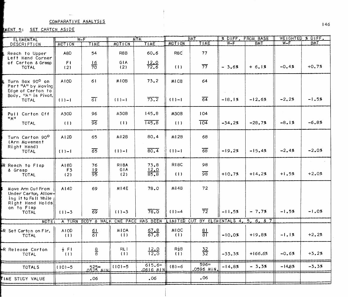
COMPARATIVE ANALYSIS 146
ELEMENT 5: SET CARTCN ASIDE
ELEMENTAL • DESCRIPTION
W-F MTM BMT % DIFF. FROM BASE WEIGHTED % DIFF. MOTION TIME MOTION TIME MOTION TIME W-F BMT W-F BMT
Reach to Upper Left Hand Corner of Carton & Grasp
TOTAL
A8D
Fl
54
TI6
R8B
GIA
60.6
TI2.0
R8C
(I)
77
77 - 3.6% + 6.1% -0.4% +0.7% (2) 70 (2) 72.6
Turn Box 90° on Part "A" by Moving Ed ge of Carton to Body. "A" is Pivot.
TOTAL
AIOD 6TI MIOB 73.2 MIOB
(TI)-I
64
64 -18.1% -12.6% -2.2% -TI.5% (TI)-I 6TI (TI)-TI 73.2
Pull Carton Off "A"
TOTAL
A300 96 M30B 145.8 M308 104
-34.2% -28.7% -8.1% -6.8% (1) 96 (I) TI45.8 (TI) 104
Turn Carton 90° (Arm Movement Ri ght Hand)
TOTAL
AI2D 65 M12B 80.4 M12B
(1)-I
68
68
-TI9.2% -15.4% -2.4% -2.0% (TI)-I 65 (1)-1 80.4
'OR Reach to Flap & Grasp
TOTAL
A18D F3
76 TI9
RI8A GIA
73.8 TI2.0
RI8C
(1)
98
98
+10.7% +TI4.2% +TI.5%
+2.0% (2) 95 (2) 85.8
Move Arm Out From Under Carton, Allow- ing ittoFall While Ri ght Hand Holds on to Flap
TOTAL
A14D
(TI)-3
69
69
M14E
(TI)-3
78.0
78.0
MI4B
(1)-4
72
72 -11.5% - 7.7% -TI.5%
-TI.0%
NOTE: A TURN BODY & WALK ONE PACE HAS BEEN LIMITED OUT BY ELEMENTALS 44 5, 6, & 7
R Set Carton on Flr. AIOD 6TI M10A 67.8 MIOC (I)
81 81 -10.0% +TI9.8% -1.1% +2.2% TOTAL (1) 6TI (1) 67.8
R Release Carton Fl 8 RLI TI2.0 RiB (I)
32 32 -33.3% +TI66.6% -0.6% +3.2% TOTAL (1) 8 (TI) TI2.0
TOTALS (10)-5 525= .0525 MIN.
(10)-5 0616
615.6= N . MIN
(8)-6 596= .0596 MIN. .0596
-14.8% - 3.3% -I4.8% -3.3%
TIME STUDY VALUE .06 .06 .06

Discussion: Element 5, Set Carton Aside
147
Reason(s) for Variation Between the Elementals
Here again exists a case of what has been
previously discussed many times, namely; that
the BMT "reach" contains a "grasp", but that
grasp cannot be analyzed. The definitions for
the "reach" part of the motions are all com-
parable by analysis though not in so many words,
but the "grasp" part of the BMT reach remains a
mystery. The exact nature of the grasp contained
therein is not known.
This motion deals simply with pulling the
carton towards the body as it rests on part
"A" and uses same as a pivot point. The
definitions here are all straightforward,
stating that the carton be moved to an approxi-
mate location and muscular control be used to
stop the carton. All of the definitions fit
the situation and imply the same thing, if not
saying it in exactly the same manner.
Here the comments immediately above apply,
since the motion simply involves moving the
carton to an approximate location and requiring
muscular control to stop the motion. The
Elemental Number
2
3

I48
definitions all fit the situation, but the
time values are out of line as compared to
one another.
Here the carton is turned from a vertical to
a horizontal position using the left hand as
a pivot. The left hand motion (turning motion)
is limited out by the movement of the right
hand. All of the definitions imply a move
with a stop at the end and compare quite well.
Same comments as "Elemental I."
The movement of the carton cannot begin until
the left hand is taken out from under the
carton and moved out of the way. Then the
carton can drop while the right hand holds on
to the flap. The left hand motion is limiting
here and is well defined by all definitions,
but particularly well by MTM which states that
the hand is moved out of the way. The other
two definitions imply a stop at the end of the
motion. They all point to the same thing.
In this move, the operator is to relinquish
control of the carton as soon as the object
touches the floor. All definitions imply the
placing of an object and compare quite favorably.
4
5
6
7

8
149
The release in this case is represented by
a simple opening of the fingers. The MTM
release spells this out in exact language,
whereas with the Work-Factor and BMT
definitions the opening of the fingers must
be analyzed. The Work-Factor simple release
has been standardized as Fl. The BMT "B"
reach was used because the fingers essentially
open up and muscular control stops the opening
process when necessary. The BMT time value is
ridiculously out of line simply because the
definition states that any reach includes a
simple grasp - how can a release include a
grasp? This is obviously contradictory. The
value was used because it was all that was
available.
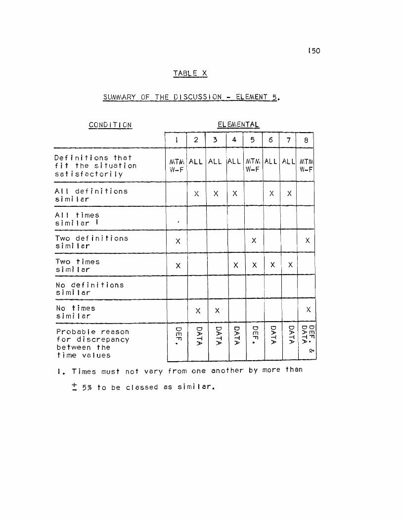
150
TABLE X
SUMMARY OF THE DISCUSSION - ELEMENT 5.
CONDITION ELEMENTAL
1 2 3 4 5 6 7 8
Definitions that fit the situation satisfactorily
MTM W-F
ALL ALL ALL MTM W-F ALL ALL MTM W-F
All definitions similar
X X X X X
All times similar 1
Two definitions similar
X X X
Two times similar X
x X x x
No definitions similar
No times similar
x X X
Probable reason for discrepancy between the time values
1. Times must not vary from one another by more than
± 5% to be classed as similar.
DE
F.
& D
ATA
DA
TA
DA
TA
DE
F.
DA
TA
DA
TA
DA
TA
DE
F.

151
CYCLE TIME WE % DIFFERENCE ANALYSIS
Weighted % Diff. On Basis Of Cycle Time
ELEMENTAL NO.
TYPE OF MOTION W-F BMT
1
2 3 4 5
Body Motion (Turn Body)
Body Motion (Walk) Reach & Grasp Move Body Motion
(Side Step)
SUB TOTAL
.28%
+1.95% - .01% + .30% -1.65%
+0.31%
- .04%
+ .49% + .45% - .06% -1.86%
-1.02%
ELEMENT 1
Weighted % Diff. On Basis Of Cycle Time
ELEMENTAL NO.
TYPE OF MOTION W-F BMT
1 2 3 4 5 6 7 8 9 0 1 2 3 4 5 6 7 8 9
Move Release Reach & Grasp Grasp Move Move Move Move Release Reach & Grasp Move Move Reach & Grasp Move Reach & Grasp Move Reach & Grasp Move Release
SUB TOTAL
+ .06% - .10% .03%
- .03% -1.27% - .18% - .44% - .43% - .10% - .25% - .10% - .10% + .10% - .38% - .02% - .10% - .02% - .10% + .03%
-3.36%
+ .74% + .49% + .01% + .18% -1.00% + .23% - .58% + .09% + .49% + .15% - .15% - .15% + .40% - .30% + .24% - .15% + .24% - .15% - .12%
+ .66%
ELEMENT 2

I52
CYCLE TIME WE % DIFFERENCE ANALYSIS (CONTINUED)
Weighted % Diff. On Basis Of Cycle Time
ELEMENTAL NO.
TYPE OF MOTION W-F BMT
1
2
3 4 5 6
Body Motion (Trunk)
Body Motion (Side Step)
Move Position Move Move
SUB TOTAL
+1.88%
-1.79%
.16%
.44%
.94%
.04%
1.49%
0.0%
-1.97%
+ .04% - .08% - .85% + .35%
-2.51%
ELEMENT 3
Weighted % Diff. On Basis Of Cycle Time
ELEMENTAL NO.
TYPE OF MOTION W-F BMT
I 2 3 4 5 6 7 8 9 10 11 12 13
Body Motion (Leg) Body Motion (Leg)
---- PROCESS Move Body Motion (Leg) Move Move Body Motion (Leg) Move Move Body Motion (Leg)
---- PROCESS Body Motion (Leg)
SUB TOTAL
-1.00% + .30%
TIME - .04% - .09% + .14% .00%
- .09% + .14% - .40% - .09%
TIME -1.00%
-2.13%
-1.31%
+ .18% ----
+ .18%
+ .18% + .58% + .30%
+ .18% + .58% - .04%
.+ .18% ---- -1.32%
- .31%
ELEMENT 4

153
CYCLE TIME WE % DIFFERENCE ANALYSIS (CONTINUED)
We % Diff. On Basis Of Cycle Time
ELEMENTAL NO. TYPE OF MOTION W-F BMT
I 2 3 4 5 6 7 8
Reach & Grasp Move Move Move Reach & Grasp Move Move Release
SUB TOTAL
- .06% - .32% -1.21% - .37% + .22% - .22% - .16% - .10%
-2.07%
+ .11% - .22% -1.02% - .30% + .30% - .15% + .33% + .49%
- .46%
ELEMENT 5

154
COMPOSITE ANALYSIS
ELEMENT 1 Elemental
N o. COMPOSITE ANALYSIS Number of
Symbols * W-F MTM BMT
1 2 3 4 5
260 60 54
111.6
244.2
(1) (1) (2) (3) (1)-3
ELEMENT 1: SUMMARY TOTAL TIME= .0730 MIN. (8)-3
ELEMENT2
No.
Elemental COMPOSITE ANALYSIS Number of Symbols * W-F MTM BMT
1 2 3 4 5 6 7 8 9 10 11 12 13 14 15 16 17 18 19
64 32 65
48
48
12.0
103.8
12.0 65.4 58.2 58.2
80.4
58.2
58.2
60
39
90
52
52
(1) (11 (3) (1) (1)-1 (1) (I) (1)-1 (1) (2) (
(1) -2 (1)
(1) (1)
(1) (1)
(1)
(2)
ELEMENT 2: SUMMARY TOTAL TIME= .1056 MIN. (231-4
* 1st No. = Limiting Motion Symbol(s) used in analysis
2nd No. = Limited Out Motion Symbol(s) used in analysis
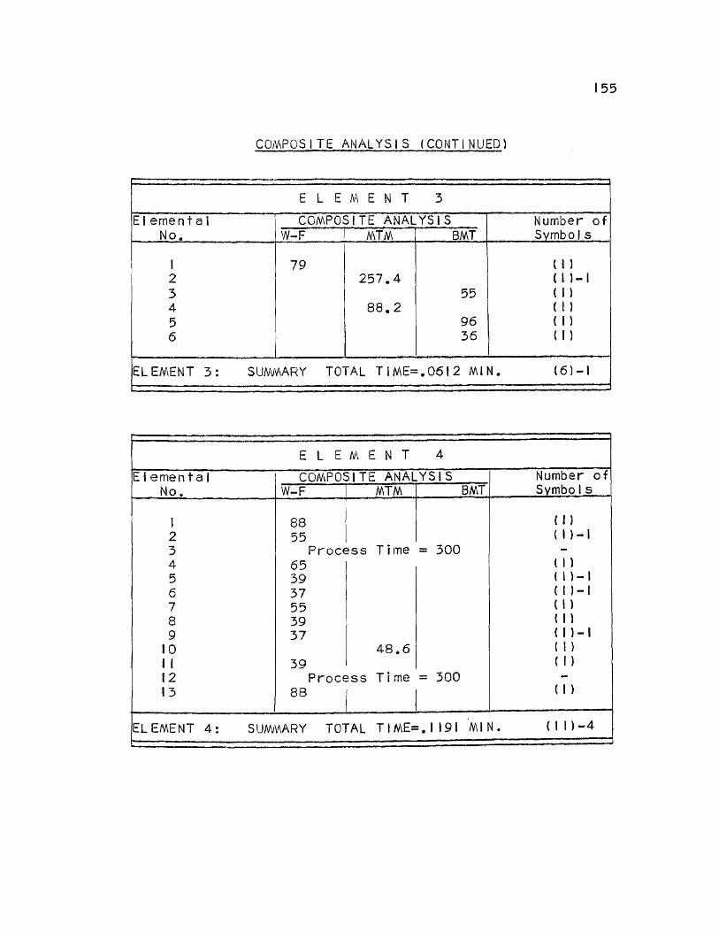
COMPOSITE ANALYSIS (CONTINUED)
ELEMENT3
Elemental No.
COMPOSITE ANALYSIS Number of Symbols W-F MTM BMT
1 2 3 4 5 6
79 257.4
88.2 55
96 36
(I) (1)-1 (1) (1) (1) (I)
ELEMENT 3: SUMMARY TOTAL TIME=.0612 MIN. (6)-1
ELEMENT4
Elemental COMPOSITE No.
ANALYSIS Number of Symbols W-F MTM BMT
1 2 3 4 5 6 7 8 9 10 11 12 13
88 55
Process 65 39 37 55 39 37
39 Process
88
Time
48.6
Time
= 300
= 300
(1) (1)-1
(1) ( )-1
(1)-1 (1 )
(1) (1)-1
(1) (1)
(I)
ELEMENT 4: SUMMARY TOTAL TIME=.1191 MIN. (11)-4
155

COMPOSITE ANALYSIS (CONTINUED)
ELEMENT5 Elemental I
No. W COMPOSITE ANALYSIS Number of
Symbols -F MTM BMT
I 2 3 4 5 6 7 8
95
72.6 73.2 145.8 80.4
78.0
12,0 81
(2) (1)-1 (I) (1)-1 (2) (1)-3 (I) (1)
ELEMENT 5: SUMMARY TOTAL TIME=.0638 MIN. (10)-5
156
TOTAL CYCLE TIME = .4227 MIN.

157
SUMMARY
The purposes of Chapter IV are: First, to set forth
an analysis which would compare each of the predetermined
time systems, elemental by elemental, so that definite
conclusions could be drawn as to why they do or do not
compare; secondly to establish which of the systems was
the quickest and easiest to use in the analysis of the
operation considered; and thirdly to present a composite
analysis of the operation "Make Cartons" through a use
of the most realistic definitions of all three systems.
The conclusions drawn from the comparison charts,
discussions, summary charts and composite analysis are
presented in the next chapter, along with several
recommendations concerning the use of the systems and
suggestions for further study.

CHAPTER V
CONCLUSIONS AND RECOMMENDATIONS
CONCLUSIONS
Comparison of the Elementals From the Comparative Analysis of Chapter IV, pages
116 to 146, it has been determined from an examination
and search of the column entitled "X Difference from
Base", that of 147 (49 x 3) elemental comparisons,
roughly 60 elementals (3 within each grouping compared)
or 41% of the total compared with each other within the
± 5% range as far as time values are concerned. (The
5% standard Time Study acceptable time difference has
been used here as well as throughout the text for com-
parison purposes.) The other 59% of the elementals (as
grouped and compared in threes) are different from one
another by an amount greater than ± 5%. The question to
be asked here is whether or not these per cent differences,
as far as individual elementals are concerned, are really
important in terms of their effect on the comparison of
the final cycle times. In other words, what is the nature
of the effect of individual elemental differences on total
cycle time?
To answer this question it must be realized, as
previously explained, that a large individual elemental

I59
per cent difference (as compared to one another) may affect
the total element time very little if its time value is
very small compared to total element time. In the Com-
parative Analysis, the column entitled "Weighted %
Difference" (from base) brings this principle out very
nicely. Referring to the analysis, pages 116 to 146,
notice how the individual difference percentages from
base are all lessened by quite an amount in the next
column to the right, "Weighted % Difference", in direct
proportion to the amount of total element time that the
elemental takes to perform. The latter weighted per-
centages are additive and their algebraic sum represents
the total percent difference of one total element time as
compared to another. Hence, for example the algebraic
sum of the BMT column under "Weighted % Difference" would
represent the per cent difference between the total element
time of BMT as compared to the total element time of the
base, MTM. Thus, it may be concluded here that the con-
trolling factor in determining whether or not element times
will compare is not the difference in time values between
individual elementals alone, but rather the weighted
difference as well as the dispersion of "tight" (+) and
"loose" (-) values which tend to cancel one another out.
When the preceding principles are applied to elementals
as opposed to cycle time, rather than from elementals to
element time, the weighted % difference becomes smaller

160
yet and the (+) and (-) values (tight or loose values)
work to more advantage in the subsequent comparison of
those total cycle times, since there are more of them
and a better dispersion exists. The "Cycle Time Weighted
Difference Analysis" presents this in chart form, pages
151 to 153. Again, the element % difference from base
(sub-totals on chart) are additive algebraically to yield
the final % difference of one cycle time as compared to
another. An examination of this analysis vs. the original
Comparative Analysis will demonstrate how the original
(high) % differences between elementals have been reduced
drastically when compared on the basis of their effect
on overall cycle time. The tight and loose values tend
to cancel one another out. In general these cancellations
are not too favorable in the case of the Work-Factor
system. The founders of Work-Factor have implied that
the Work-Factor Select Time does not compare to the base
time of any other system of predetermined times, since
the select time does not include an allowance for incentive
payment. They do, therefore, also imply that the base
times of those other systems do include an allowance for
incentive. No where in the author's study of predetermined
time systems has the latter point been verified. It might
appear then, that this explanation is somewhat of a
"device" which very nicely explains why Work-Factor is
just a little bit "tight" when compared to the other
161
systems of predetermined times. This should not in any
way, however, be taken as a criticism of Work-Factor,
since to the author's way of thinking the system is
second to none in analyzing WHAT IS DONE in an operation.
The system of symbols, definitions and variables, is
highly universal in scope. Any general condition such
as tightness or looseness in any system of predetermined
times can very easily be adjusted to conform to an
industrial organization through use of a constant
correction factor. This, of course, will maintain con-
sistency with Time Study.
A further examination of the "Cycle Time Weighted
% Difference Analysis", pages 151 to 153, will provide a
good indication of which fundamental motions or elementals
are out of line the most as concerns their effect on total
cycle time. The first step was to take the weighted %
differences by elemental group (Body motions, moves, etc.)
and determine from the analysis chart the weighted average
ABSOLUTE % difference within each group. This was done,
for example, simply by adding all the Body Motion weighted
absolute figures together (disregarding sign) and dividing
by the total number of Body Motions used in the analysis.
In other words, what is essentially being said here is
that the elementals with larger time values (al other
things being equal) will in general tend to have the
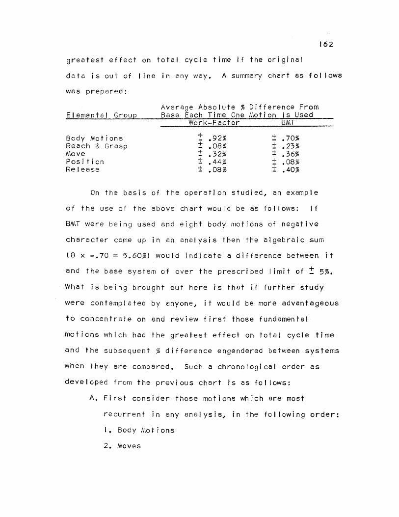
162
greatest effect on total cycle time if the original
date is out of line in any way. A summary chart as follows
was prepared:
Elemental Group Average Absolute % Difference Base Each Time One Motion
From Is Used
Work—Factor BMT
Body Motions ± .92% ± .70% Reach & Grasp ± .08% ± .23% Move ± .32% ± .36% Position ± .44% ± .08% Release ± .08% ± .40%
On the basis of the operation studied, an example
of the use of the above chart would be as follows: If
BMT were being used and eight body motions of negative
character came up in an analysis then the algebraic sum
(8 x —.70 = 5.60%) would indicate a difference between it
and the base system of over the prescribed limit of ± 5%.
What is being brought out here is that if further study
were contemplated by anyone, it would be more advantageous
to concentrate on and review first those fundamental
motions which had the greatest effect on total cycle time
and the subsequent % difference engendered between systems
when they are compared. Such a chronological order as
developed from the previous chart is as follows:
A. First consider those motions which are most
recurrent in any analysis, in the following order:
I. Body Motions
2. Moves

163
3. Reaches and Grasps
B. Other Motions
1. Position
2. Release
Hence, the above represents the most advantageous order
of attack (from the standpoint of doing the most good as
soon as possible) for further study of the validity of
those motions as they affect differences in total cycle
times when one system is compared to another.
The next problem is to take each group of elementals
and determine how to analyze the data for that group if
further study is contemplated. In short, the question
must be asked, "Should the validity of the original data
of each system be analyzed first or are the definitions
of elementals as presented by each system primarily to
blame for the time values being out of line with one
another"? For the answer to this one must refer to the
Discussion Summary Sheets which follow the Comparative
Analysis of each elemental, pages 120 to 150. At the
bottom of each summary sheet is indicated the probable
reason(s) for discrepancy between the elemental time
values. These reason(s) were determined for each elemental
through an examination of the Comparative Analysis and the
Discussion which follows each. The summary on the follow—
ing page will prove helpful.

164
* One of the elementals was omitted here because all of
the definitions as well as all of the times compared
favorably for that elemental.
From the above summary, it is rather difficult to
say which classification held the greatest weight as far
as causing individual elementals to be out of the ± 5%
limit when compared to one another. However, it is the
opinion of the author that if anything, it would appear
from the results that the data should be checked first.
The results as presented above do tend to lean in this
direction at any rate.
Hence, there has been established in the preceding
paragraphs, a chronological order for further study of the
elementals, and also how to treat each elemental group
in that study. The entire order of study was developed
from the standpoint of doing the greatest good in the
shortest amount of time.

165
Use of the Systems
Composite analysis. The cycle time values of the
three predetermined time systems as compared to one
another have already been determined for the operation,
"Make Cartons", to be as follows:
I. Work-Factor 3731 minutes
2. MTM 4107 minutes
3. BMT 3954 minutes
An inspection of the differences in times as well
as the experience gained in analyzing the operation
indicated the following things to the author:
I. Any one of the systems might perhaps have a
definition for an elemental motion which would fit a
specific situation, but many times a definition from
another system would fit the situation better, simply
on the merit of the actual wording of the definition
and/or the number of variables which it considered. In
other words, very often a specific elemental definition
of a specific system really did not fit the situation too
well, but it had to be used since it was the only value
available and was, in effect, "better than using nothing
at all". (See Discussion Summary Sheets, pages 120 to
150.)
2. At times any one system might not, have any
elemental definition at all to fit the situation. (This

166
occurred once in the analysis but could conceivably occur
many times in other analyses).
The above considerations led the author to believe
that there might be some particular advantage to using
the most realistic elemental definitions of ALL of the
systems to analyze a cycle and in so doing perhaps come
closer to the time study cycle time value. From this
standpoint the idea seemed to have enough merit to warrant
the presentation of a "composite analysis" of the operation
"Make Cartons" as presented in the preceding chapter. The
following "rules" were used in the Composite Analysis:
1
. Considering each elemental, select and use for
that elemental the definition from any one of the three
systems which best fits the situation.
2. If two or more definitions fit the situation
equally well, then use the one which gives the highest
time value.
The final cycle time value as determined by the
Composite Analysis was found to compare more favorably
to the Time Study value than that of any one of the other
three systems. The chart on the following page indicates
the comparison of the time values of the four systems to
Time Study.

167
Time Value From Cycle Time For Operation, "Make Cartons"
Time Study Composite Work-Factor MTM BMT
.42
.4227
.3731
.4107
.3954
In addition, it is interesting to note that of a total
of 49 elementals being analyzed in the Composite Analysis,
20 were selected from Work-Factor, 20 from MTM and 9 from
BMT; or 40.8%, 40.8% and 18.4% of the total respectively.
The use of BMT was somewhat restricted because of its
reach which included a grasp. For most situations en-
countered, this was felt not to be a good analysis, as
previously discussed many times, because the exact nature
of the "included" grasp could not be readily determined.
Which system is quickest and easiest to use? (Based
on the operation that was analyzed) The question posed
above requires that the investigation to be made include
the actual number of symbols used in each analysis by
each predetermined time system. In this investigation,
in order to give a truer picture of the actual amount of
symbol writing involved in each individual analysis, it
was decided to include in the total the symbols for
motions which are limited out as well as for those which
are limiting. (Limited out motions must be written down
in the analysis as well). The results are taken from the

168
Comparative and Composite Analysis Sheets of Chapter IV,
pages 116 to 156, and are as follows:
System Number of Symbols Used in the Analysis
Composite Work-Factor MTM 6MT
75 80 73 66
The above chart states, in effect, that on the basis
of the operation that was analyzed, BMT is the quickest
and easiest system to use, MTM was second, and Work-Factor
the most time consuming. Impressions gained from actually
analyzing the operation bear this out. It must be noted
that the figure for the composite analysis is not realistic
because that analysis considers three elemental definitions
for each definition that is written down on the final
composite analysis sheet. Hence the amount of work encoun-
tered in using the composite system would be multiplied
approximately threefold, if not more.
RECOMMENDATIONS
Concerning Further Study of the Predetermined Time Systems
Comparison of the systems one to another (elementals).
As per the conclusion, the following chronological order
of study of the basic motions or elementals is advised on
the basis of the accuracy it can add to the systems in
bringing their time values more in line with one another

169
in the shortest possible period of time.
Chronological Order Of Study
Considerations Within Each Group In Order Of Importance
1. Body Motions a, Data b. Definitions
2. Move a. Data b. Definitions
3. Reach and Grasp a. Data b. Definitions
4. Position a. Data b, Definitions
5. Release a. Data b. Definitions
Comparison of the systems to time study. This is
a different picture entirely from the general theme upon
which this thesis has concentrated. In order to compare
any predetermined time system (PTS) to Time Study, there
must first be available many time studies and their
respective PTS analyses. In short, there must exist a
representative sample. Each individual time study result
should be compared to its respective PTS analysis and the
cycle time differences noted and recorded. After the
proper sample size (number of studies to be considered)
has been determined statistically, the analysts must treat
this data, again statistically, to determine whether or
not there is a significant difference between Time Study
170
and the Predetermined Time System being used, based on
some predetermined % difference (an acceptance percentage)
that is acceptable to management. (Normally this would
be the ± 5% difference that is allowed in time study).
This type of analysis, however, will require a great
deal of time, but it is highly advisable for an industrial
organization to undertake such an investigation before
turning to full use of PTS, so that first, confidence
in the system is had by all, and secondly and more
important, that CONSISTENCY (the backbone of Time Study)
is maintained. Even if it is discovered that the time
values exceed the ± 5% acceptance percentage as described,
the PTS values may all be adjusted by a constant correction
factor as determined from the "representative sample"
analysis. This procedure will maintain consistency
between those time standards already in effect and the
predetermined time system to be installed. This entire
course of action is, of course, only to be taken if the
management of a company decides that the use of a pre—
determined time system is worthwhile either on a "full
or a part time" basis.
Concerning Use of the Systems
Composite system. The results of the Composite
Analysis, pages 154 to 156, indicate the existence of
a definite trend toward the validity of the thinking

171
that a composite type analysis which uses the "best" of
all predetermined time systems is an excellent answer
to the question, "Which system shall I use?".
Of course, the problem of practicality enters at
this point, since the Industrial Engineers of a company
would have to put forth much time and effort in
familiarizing themselves with all of the established
systems of predetermined time standards. It is a known,
but oft neglected fact that the uninitiated should never
attempt to use a predetermined time system without adequate
study and experience with the system-in-question. Hence,
from this standpoint, the idea of a composite system may
not be given further consideration from many industrial
organizations, since such an intricate knowledge of all
of the systems is involved. Perhaps the idea of a composite
system will receive more attention in the future when the
various systems of predetermined times are better known.
Nonetheless, regardless of the practicality as
discussed, the results of the Composite Study as brought
forth in the Conclusions do show a definite trend towards
producing a cycle time which compares much more favorably
to the time study value than any one of the other three
systems of predetermined time standards. This is so
most probably because the Composite System takes into
account the most realistic elemental definitions of each
172
system. It is the author's opinion that properly used,
a System of Composite Analysis would be quite worthwhile,
and would fit quite well into the plans of any industrial
organization contemplating the use of a system of
predetermined times.
Standard systems. If it is desired to select any one
of the three predetermined time systems (Work-Factor, MTM,
BMT) for use in an industrial organization, it might be
wise to study the Discussion and Summary Charts of Chapter
IV as well as the description of how to use each system
as presented in Chapter 11. Much of this information can
serve as an excellent basis for comparison between the
systems, and should prove valuable as an aid in helping
one decide which system best fits the needs of the
company-in-question. Also the fact that one may observe
each system as it is used to analyze the same operation
may be classed as a distinct aid in the selection of a
predetermined time system.
It might be added here that if full or part time
use of any one of the predetermined systems is contemplated
then a progressive management should:
1. Make sure that their Industrial Engineers have
proper training in the system of their choice, such
training being given by qualified personnel.
2. Undertake the statistical investigation of the

173
Time Study and PTS data as set forth in the Conclusions.
Consideration of these two points will greatly
increase the probability of the successful use of any
system of predetermined times within an industrial
organization.

CHAPTER VI
CRITICAL EVALUATION
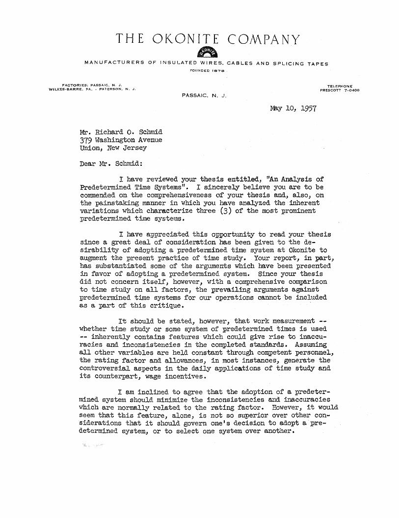
THE OKONITE COMPANY
MANUFACTURERS OF INSULATED WIRES, CABLES AND SPLICING TAPES
FOUNDED 1878
FACTORIES: PASSAIC, N. J. TELEPHONE WILKES-BARRE, PA. - PATERSON, N. J. PRESCOTT 7-0400
PASSAIC, N. J,
May 10, 1957
Mr. Richard 0. Schmid 379 Washington Avenue Union, New Jersey
Dear Mr. Schmid:
I have reviewed your thesis entitled, "An Analysis of Predetermined Time Systems". I sincerely believe you are to be commended on the comprehensiveness of your thesis and, also, on the painstaking manner in which you have analyzed the inherent variations which characterize three (3) of the most prominent predetermined time systems.
I have appreciated this opportunity to read your thesis since a great deal of consideration has been given to the de-sirability of adopting a predetermined time system at Okonite to augment the present practice of time study. Your report, in part, has substantiated some of the arguments which have been presented in favor of adopting a predetermined system. Since your thesis did not concern itself, however, with a comprehensive comparison to time study on all factors, the prevailing arguments against predetermined time systems for our operations cannot be included as a part of this critique.
It should be stated, however, that work measurement --whether time study or some system of predetermined times is used -- inherently contains features which could give rise to inaccu-racies and inconsistencies in the completed standards. Assuming all other variables are held constant through competent personnel, the rating factor and allowances, in most instances, generate the controversial aspects in the daily applications of time study and its counterpart, wage incentives.
I am inclined to agree that the adoption of a predeter-mined system should minimize the inconsistencies and inaccuracies which are normally related to the rating factor. However, it would seem that this feature, alone, is not so superior over other con-siderations that it should govern one's decision to adopt a pre-determined system, or to select one system over another.

- 2 -
In the first part of your thesis you have very capably presented the background of predetermined time systems and, also, presented most of the advantages associated with the use of them. I do not believe that these alleged advantages can be, generally applied to all types of operations. I believe that predetermined time systems predominate at only one end of the spectrum -- partic-ularly on fine assembly operations where micro-motion study could also be advantageously applied. In most other areas, I believe that some very cogent arguments could be presented in favor of con-ventional time study.
I cannot completely agree that the evolution of a System of Composite Analysis is the solution for reconciling the problem of which system a company should adopt. The results of each system do not compare so unrealistically that refinement, to the degree of a composite system, is required.
The essence of the selection would be to select a system of predetermined time values which would be applicable -- within the accepted degree of deviation -- to supplement a conventional time study system. Any company which has been using time study to good advantage for any period should be able to select, and support statistically, the system which gives the desired accuracy and ease of application.
One further thought should also be expressed concerning the development of a standard data system which uses information a company has developed and applied successfully. I would expect that it would be a very time consuming and unrewarding program to develop facility with any more than one system of predetermined time values. You have not particularly emphasized ,the development of predetermined time values based on time study information which has been converted to standard data; but I would recommend that this would prove much more beneficial to a company than adopting a system of time values which could not get their genesis within the company's operations.
All in all, I believe you have handled the subject matter quite expertly and have provided any reader with a deep insight into systems of predetermined values. My comments would not take exception in any way with the accuracy of your data, but rather with the practical relationships which should be associated with any system of work measurement.
Very truly yours,
V. A. VIGGIANO, DIRECTOR OF INDUSTRIAL ENGINEERING
THE OKONITE COMPANY.
VAV:ks

25 Grant Avenue, Clifton, New Jersey May 16, 1957
Professor 0. J. Sizelove Department of Management Engineering Newark College of Engineering Newark, New Jersey
Dear Professor Sizelove:
I have read the thesis submitted to you by Mr. R. 0. Schmid entitled, "An Analysis of Pre-determined Time Values," and the following is my critical evaluation thereof.
Mr. Schmid has written a well-organized thesis which uses a sound approach in attempting to compare the various systems under consideration. It is my opinion, that he has made an excellent start towards weighing the factors involved and pre-senting a sound approach for future research in this direction. However, there are several features which require revision be-fore the conclusions indicated are accepted on face value.
1) It is apparent from a cursory study of the analysis sheets that the writer has not had substantial experience in the application of the specific techniques. Despite this lack of experience, he arrives at reasonably accurate results but before further developments are made upon this base, these analyses should be reviewed for their accuracy.
2) The conclusions at which Mr. Schmid arrived at were, of necessity, based upon a very small sample. If this type of research were extended by experienced personnel and a statis-tically reliable sample were employed, the results obtained would have more weight in the profession.
3) Mr. Schmid's analysis points up one of the basic problems in evaluating pre-determined time values that is the fact that some of the elemental descriptions employed are not sufficiently discriminating to enable the user to apply them without rationalizing their meanings.
4) Comment was made in the thesis in an interpretation of the Work Factor technique that its time values are a bit on the tight side, and that its explanation was merely a device to explain this away. It should be noted that since the inception of Work Factor, the authors have maintained this same state-ment and have not adjusted their time values to cover this up.

-2-
5) Mr. Schmid suggests the possibility that a solution in this problem is to develop a composite system. Several attempts have been made at this, namely; General Electric Company, etc., and the resulting systems have not been much of an improvement. It is my suggestion that instead of trying to develop a com-posite system, that some person or group select one of the systems which they feel has merit and work out the specific problems on this system to meet the criteria which have been established.
6) Lastly, Mr. Schmid suggests a sequence for further study and indicates that the data should be revaluated first, and then the definitions clarified later. It should be noted that if the definitions are not sufficiently clarified before the data is collected, the results will be of little value since the data will be collected on one basis, while the definitions will be established on another basis. Again, it is my suggestion that firstly, we agree upon adequate definitions and then col- lect the data in consonance with the definitions.
In summary, I feel that my qualifications of this thesis are minor compared with the basic work which Mr. Schmid has done. However, I think that if these few modifications are made and further study is developed, we might achieve the goal that Mr. Schmid and others of us have been seeking for years.
Yours truly,
John Feltman
JF:bc
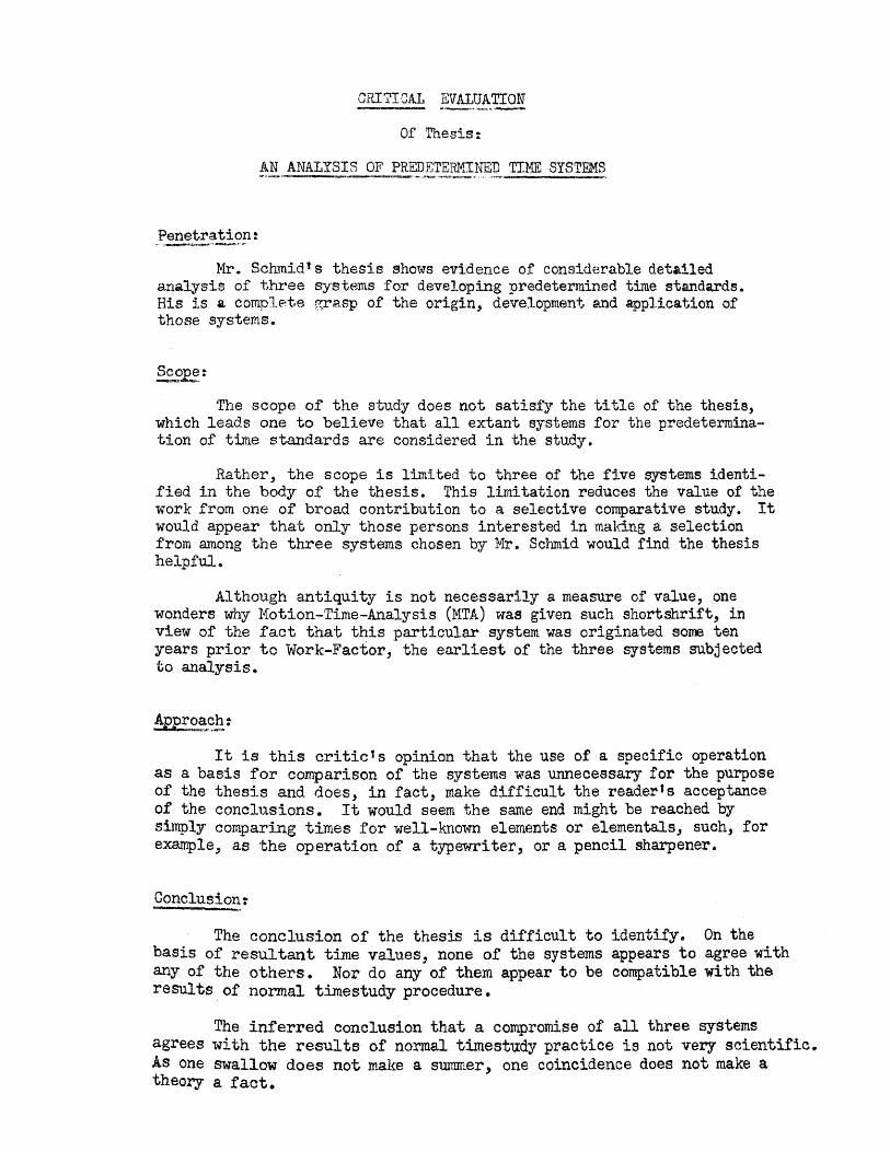
CRITICAL EVALUATION
Of Thesis:
AN ANALYSIS OF PREDETERMINED TIME SYSTEMS
Penetration:
Mr. Schmidts thesis shows evidence of considerable detailed analysis of three systems for developing predetermined time standards. His is a complete grasp of the origin, development and application of those systems.
Scope: The scope of the study does not satisfy the title of the thesis,
which leads one to believe that all extant systems for the predetermina-tion of time standards are considered in the study.
Rather, the scope is limited to three of the five systems identi-fied in the body of the thesis. This limitation reduces the value of the work from one of broad contribution to a selective comparative study. It would appear that only those persons interested in making a selection from among the three systems chosen by Mr. Schmid would find the thesis helpful.
Although antiquity is not necessarily a measure of value, one wonders why Motion-Time-Analysis (MTA) was given such short shrift, in view of the fact that this particular system was originated some ten years prior to Work-Factor, the earliest of the three systems subjected to analysis.
Approach:
It is this critic's opinion that the use of a specific operation as a basis for comparison of the systems was unnecessary for the purpose of the thesis and does, in fact, make difficult the reader's acceptance of the conclusions. It would seem the same end might be reached by simply comparing times for well-known elements or elementals, such, for example, as the operation of a typewriter, or a pencil sharpener.
Conclusion:
The conclusion of the thesis is difficult to identify. On the basis of resultant time values, none of the systems appears to agree with any of the others. Nor do any of them appear to be compatible with the results of normal timestudy procedure.
The inferred conclusion that a compromise of all three systems agrees with the results of normal timestudy practice is not very scientific. As one swallow does not make a summer, one coincidence does not make a theory a fact.

- 2
Usefulness:
Perhaps the most useful feature of the thesis is the conclusion that much more study will be needed before the validity of the principle of predetermined time standards can be proved. From the point of view of the industrial manager, reliable answers to the following questions need to be developed:
1. Is there a system which is better than normal timestudy procedure for the determination of standard times for specific operations?
2. If so, how is such a system better; is it less costly in application; does such a system give more uniform results?
Composition:
Length is perhaps the most obvious characteristic of the thesis. One gets the impression that a careful editing job would improve considerably the readability of the work and would result in pruning out much of the well-known material.
The thesis would be much more readable if it were presented somewhat in reverse. That is, the conclusions first, then the detail supporting the conclusion and finally, in appendix form, the historical data concerning the various systems.
W. F. Weir 5/13/57 Plant Manager
The Okonite Company Passaic, New Jersey

181
BIBLIOGRAPHY
Abruzzi, Adam, Work Measurement New Principles and Procedures. New York: Columbia University Press, 1952.
Alford, L. P. and Bangs, John R., Production Handbook, New York: The Ronald Press Company, 1953.
Anonymous: "Application of the Work-Factor Technique," Machinery (London), Vol. 87, September 23, 1955, pp. 729-30.
Anonymous: "How Good is MTM," Factory Management and Maintenance, Vol. 108, August, 1950, pp. 83-91.
Anonymous: "Methods-Time Measurement," Modern Industry, Vol. 22, August 15, 1951, pp. 76-77.
Anonymous: "Predetermined Time Standards," Factory Management and Maintenance, Vol. III, September, 1953, pp. 134-39.
Anonymous: "Short Cuts to Productivity," Modern Industry, Vol. 19, May 15, 1950, pp. 41-47.
Anonymous: "Stretching Engineering Skill with Predetermined Time Standards," American Society of Mechanical Engineers, Paper n52 SA-60 for Meeting June 15-19, 1952.
Anonymous: "Timing a Fair Day's Work," Fortune, Vol. XL, October, 1949, pp. 129-132.
Barnes, Ralph M., Motion and Time Study, Third Edition. New York: John Wiley and Sons, Inc., 1949.
Barnes, Ralph M., Work Measurement Manual, Third Edition. Dubuque, Iowa: Wm. C. Brown Co., 1947.
Brooks, W. Gilbert, "How Pitney-Bowes Applies Work Measurement to Its Office," Advanced Management, Vol. 19, December, 1954, pp. 8-11.
Davis, Louis E., "A Proposal for the Improvement of Time Study," Mechanical Engineering, Vol. 71, May, 1949, pp. 399-402.
Duncan, J. H., "Work-Factor System of Predetermined Times for Movements," Machinery (London), Vol. 81, December 5, 1952, pp. 1197-98.
182
Engstrom, Harold, "Predetermined Time Standards," Advanced Management, Vol. 17, April, 1952, pp. 16-17.
Farr, Donald E., "What Management Problems Can MTM Help Solve?" (Reprint of Speech by Mr. Farr who is Vice President of Engineering, Methods Engineering Council).
Geppinger, H. C., DMT Dimensional Motion Times Development and Application. New York: John Wiley and Sons, Inc., 1955.
Geppinger, H. C., "New Motion-Time Method Defined," The Iron Age, January 8, 1953, pp. 106-108.
Geppinger, H. C., "Planned Time Study Standards," The Iron Age, October 29, 1942, pp. 34-36.
Godwin, G. A., "Basic Principles of Work-Factor System of Time and Motion Study," Machinery (London), Vol. 85, October I, 1954, pp. 715-19.
Hodson, William K., "Practical Aspects of Methods-Time Measurement." (Reprint of speech by Mr. Hodson who is Engineering Manager, Methods Engineering Council).
Holmes, Walter G., Applied Time and Motion Study. New York: The Ronald Press Company, 1938.
Kelly, John S., "Establishing Finishing Operation Rates With Elemental Time Standards," Metal Finishing, Vol. 49, March, 1951, pp. 71-74.
Lowry, S. M., Maynard, H. B. and Stegemerten, G. J., Time and Motion Study For Wage Incentives, Third Edition. New York: The McGraw-Hill Book Co., Inc., 1940.
Maynard, H. B., Editor-in-Chief, Industrial Engineering Handbook, First Edition. New York: The McGraw-Hill Book Co., Inc., 1956.
Maynard, H. B., "Methods-Time Measurement Application Experiences." (Reprint of speech by Mr. Maynard who is President of the Methods Engineering Council).
Maynard, H. B,, Stegemerten, G. J. and Schwab, J. L., Methods-Time Measurement, First Edition. New York: The McGraw-Hill Book Co., Inc., 1948.
Maynard, H. B., Stegemerten, G. J. and Schwab, J. L., "Methods-Time Measurement," Factory Management and Maintenance, Vol. 106, February, 1948, pp. 97-104.

163
Mogensen, Allen H., Common Sense Applied To Motion And Time Study. New York: The McGraw-Hill Book Co., Inc., 1932.
Morrow, Robert Lee, Time Study and Motion Economy. New York: The Ronald Press Company, 1946.
Mundel, Marvin E., Systematic Motion and Time Study. New York: Prentice-Hall, Inc., 1947.
Nodler, Gerald, Motion and Time Study. New York: The McGraw-Hill Book Co., Inc., 1955.
Niebel, B. W., Motion and Time Study. Homewood, Illinois: R. D. Irwin, 1955.
Niebel, B. W. and Thuering, G. L., "Let's Have More Accurate Time Standards for Basic Motions," Factory Management and Maintenance, Vol. 109, September, 1951, p. 101.
Olson, R. A., "Setting Time Standards Without A Stopwatch," Factory Management and Maintenance, Vol. 104, February, 1946, pp. 92-96.
Presgrave, Ralph, The Dynamics of Time Study, Second Edition. New York: The McGraw-Hill Book Co., Inc., 1945.
Quick, J. H., Shea, W. J. and Koehler, R. E., "Motion-Time Standards," Factory Management and Maintenance, Vol. 103, May, 1945, pp. 97-108.
Shaw, H. D., "Methods-Time Measurement," Digest of Address, American Society of Mechanical Engineers, Advance Paper n50 PR1-10, for Meeting Apri1 25, 1950.
Stewart, Ted C., "Work-Factor Analysis Takes Stopwatches Out of Time Study," Factory Management and Maintenance, Vol, 106, May, 1948, pp. 126-128.
Taylor, Frederick Winslow, Shop Management. New York: Harper and Brothers Publishers, 1912.
Vallette, W. J., "Measure the Work-Factor," American Machinist, Vol, 99, November 21, 1955, pp. 130-33.
White, K. C., "Predetermined Elemental Motion Times," American Society of Mechanical Engineers, Advance Paper n500 for Meeting November 26 - December I, 1950.

Woerner, Otto and lndeck, Jack, "Predetermined Time Values Told Us to Break With Tradition," Factory Management and Maintenance, Vol. 110, November, 1952, pp. 88-89.
Work-Factor Company, The Detailed Work-Factor Manual For Timestandards Analysis. New York: The Work-Factor Company, 1956.
184