copyright warning &...
TRANSCRIPT

Copyright Warning & Restrictions
The copyright law of the United States (Title 17, United States Code) governs the making of photocopies or other
reproductions of copyrighted material.
Under certain conditions specified in the law, libraries and archives are authorized to furnish a photocopy or other
reproduction. One of these specified conditions is that the photocopy or reproduction is not to be “used for any
purpose other than private study, scholarship, or research.” If a, user makes a request for, or later uses, a photocopy or reproduction for purposes in excess of “fair use” that user
may be liable for copyright infringement,
This institution reserves the right to refuse to accept a copying order if, in its judgment, fulfillment of the order
would involve violation of copyright law.
Please Note: The author retains the copyright while the New Jersey Institute of Technology reserves the right to
distribute this thesis or dissertation
Printing note: If you do not wish to print this page, then select “Pages from: first page # to: last page #” on the print dialog screen

The Van Houten library has removed some of the personal information and all signatures from the approval page and biographical sketches of theses and dissertations in order to protect the identity of NJIT graduates and faculty.

RELIABILITY CONSIDERATIONS FOR COMMUNICATION SATELLITES
BY
FRANK POLIZZI
A THESIS
PRESENTED IN PARTIAL FULFILLMENT OF
THE REQUIREMENTS FOR THE DEGREE
OF
MASTER OF SCIENCE IN MANAGEMENT ENGINEERING
AT
NEWARK COLLEGE OF ENGINEERING
This thesis is to be used only with due regard to the rights of the author(s). Bibliographical references may be noted, but passages must not be copied without permission of the College and without credit being given in subsequent written or published work.
Newark, New Jersey 1968
i
ABSTRACT
A detailed program covering all phases of reliability for
a communication satellite was presented. In long mission programs
such as this one, reliability is the prime consideration in assuring
a successful accomplishment of the stringent goals set forth. Reli-
ability principles and methods were incorporated in delineating each
major task in the program. These principles and methods not only
aided the reliability personnel in performing their duties better,
but also assisted the design group, manufacturing personnel, and
the testing and evaluation group in performing their jobs efficiently
by being aware and knowledgeable of reliability engineering.
Various reliability disciplines were imposed, as requirements,
on the different groups assigned to the high reliability program.
As each group in the program organization became aware of the many
problems encountered in this type of program, the reliability personnel
worked with each one, incorporating the methods and controls of
reliability. These methods and controls aided the design group in
designing a system with reliability as the prime consideration. The
manufacturing personnel received training and indoctrination instructions
in reliability practices, thus enabling them to build a system at the
highest level of reliability. The testing and evaluation group used
reliability and statistical analysis techniques in their testing
programs to check out the design and manufacturing of the satellite.

The results and accomplishments speak for themselves. Checking
the record to date shows a very successful phase of communications
byway of satellite. The feasibility of satellite communications
has been proven and the future for more sophisticated techniques
looks excellent.
ii
APPROVAL OF THESIS
RELIABILITY CONSIDERATIONS FOR COMMUNICATION SATELLITES
BY
FRANK POLIZZI
FOR
DEPARTMENT OF INDUSTRIAL AND MANAGEMENT ENGINEERING
NEWARK COLLEGE OF ENGINEERING
BY
FACULTY COMMITTEE
APPROVED:
NEWARK, NEW JERSEY
JUNE, 1968
iii

iv
PREFACE
Communication by means of satellite has come of age. A decade
ago this method of communicating was not feasible basically because
of the severe requirements imposed on the various electronic components.
Parts were needed that could last for many years without maintenance.
Our technology had not advanced that far at that time. Another way
of putting it: the methods and techniques of obtaining high reliable
components for the satellite were not fully developed. This paper
presents one way of designing, manufacturing, and testing a communi-
cation satellite, with reliability being the primary objective.
Chapter 1 is concerned with the historical background of
communication satellites, detailing the progress achieved since
the first successful launching of Score in December, 1958. Also
discussed in this chapter are the merits of passive communication
satellites and active communication satellites. Reliability was
introduced at this point to establish the necessary goals in
achieving a communication satellite of high reliability for mission
times of up to 5 years.
Reliability was the main concern during the stages of design.
This was accomplished by setting up an organization with the
reliability function as one of the main disciplines. A reliability
program was set up specifically to monitor and control all aspects

of the reliability tasks. Such tasks as reliability analysis and
assessments; control of processes, material, and parts; reliability
control of suppliers; failure reporting, analysis, and corrective
action feedback of all failures; reliability indoctrination and
training; reliability testing programs; and program review are
covered in some detail in Chapters 3 and 4.
In Chapter 5 are the conclusions, findings, and recommendations
of the reliability program developed for the communication satellite
system. These conclusions and recommendations are based on present
state-of-the-art techniques and methods.
I would like to express my appreciation to my advisor, Dr.
Salvatore R. Calabro, Department of Industrial and Management
Engineering, Newark College of Engineering for his suggestions and
guidance while writing this thesis; also to Mr. Anthony J. Finocchi,
Staff Consultant for Reliability and Quality Control at ITT Avionics,
a division of International Telephone and Telegraph Corporation and
Mr. Fred T. Kallet, Chief Engineer, Reliability Engineering, Kearfott
Products, a division of General Precision Systems Incorporated, for
their critical reviews and suggestions. Many thanks are also in
order to Mrs. Edward Schley, who typed the thesis most efficiently.
Most of all I wish to express my sincere thanks to my wife,
Gloria, who's encouragement inspired me in writing this thesis.
Frank Polizzi
June, 1968

vi
TABLE OF CONTENTS
Preface iv
Chapter 1. HISTORY AND INTRODUCTION OF COMMUNICATION SATELLITES 1
Historical Background 1
Introductory Remarks 13
Chapter 2. STATEMENT OF THE PROBLEM 21
Chapter 3. SOLUTION TO THE PROBLEM 45
Reliability Program Organization
Reliability Program Plan 51
Reliability Design Review 55
Reliability Apportionment, Assessment, and Analysis 66
Chapter 4. SOLUTION TO THE PROBLEM (CONTINUED) 97
Parts, Material and Process Control 97
Supplier Reliability Control 116
Failure Reporting and Analysis, and Corrective Action 119
Reliability Indoctrination and Training 124
Reliability Testing Program 132
Reliability Program Review .. 163
Chapter 5. CONCLUSIONS AND RECOMMENDATIONS • 169
Appendix I Satellites Remaining As A Function of Time 182
Appendix II Letters of Critical Evaluation 186-A
References 187

LIST OF _FIGURES
Figure 1.1 Communication Time Lag 20
Figure 3.1 Reliability Organization Chart 47
Figure 3.2 Reliability Engineering Functional Organization Chart 48
Figure 3.3 Scope of Design Reviews vs Phase of Development 56
Figure 3.4 Component Failure Rate as a Function of Age. . . 70
Figure 3.5 Failure Rates for Silicon Transistors 76
Figure 3.6 Failure Rates for Silicon Diodes 76
Figure 3.7 Failure Rates for Composition Resistors 77
Figure 3.8 Failure Rates for Film Resistors . 77
Figure 3.9 Failure Rates for Paper Capacitors 78
Figure 3.10 Failure Rates for Mica Capacitors 79
Figure 3.11 Failure Rates for Ceramic or Glass Capacitors 80
Figure 3.12 Failure Rates for Tantalum Capacitors 81
Figure 3.13 Failure Rates for Transformers and Coils . . . . 81
Figure 3.14 Failure Rates for Rotary Devices 83
Figure 3.15 Basic Configuration of Communication Satellite . 88
Figure 3.16 Redundant Configuration for Communication Satellite. 90
Figure 4.1 Summary of Flaw Failure Reporting, Analysis, and Corrective Action System 125
Figure 5.1 Probability of Survival (High-power Communication Satellites) . 179
vii

LIST OF TABLES
Table 1.1 Space Log of Communication Satellites 9
Table 2.1 Characteristics of Ground Station 24
Table 2.2 Standards for Communication System 25
Table 2.3 Frequency Modulation (TV), Ground to Spacecraft 26
Table 2.4 Frequency Modulation (TV), Spacecraft to Ground 27
Table 2.5 Single Sideband Modulation (Voice) Ground to Spacecraft 28
Table 2.6 Phase Modulation (Voice) Spacecraft to Ground 29
Table 2.7 Spacecraft Reliability Requirements 30
Table 2.8 Reliability Objectives 31
Table 3.1 Reliability Design Review Check List 63
Table 3.2 Typical Failure Rates 68
Table 3.3 Relay Base Failure Rates 84
Table 3.4 Relay Failure Rates per Contact Set 84
Table 3.5 Relay Load Factor for Contact Current Rating 85
Table 3.6 Average Failure Rates for Low Population Parts 86
Table 3.7 Failure Rates for Communication Satellite System 89
Table 3.8 Different System Configurations for Satellite System Showing Probability of Success for 1 Year 91
viii

LIST OF TABLES (Continued)
Table 4.1 Typical Screening Conditions 99
Table 4.2 Types and Typical Uses of Communication Satellite Passive Components 101
Table 4.3 Limits of Radiation Resistance of Selected Organic Coatings 115
Table 4.4 Environmental Conditions Experienced by Communication Satellites 134
Table 4.5 Concepts of Testing . . . 135
Table 4.6 Environments and Testing Parameters of Satellite Components 136
Table 4.7 Satellite Traveling Wave Tube Characteristics 147
Table 4.8 Reliability Program Evaluation Summary 166
Table A-1 Satellites Remaining as a Function of Time (MTF = 24 months) 184
Table A!-2 Satellites Remaining as a Function of Time (MTF = 60 months) 185
ix

1
CHAPTER 1
HISTORY AND INTRODUCTION OF COMMUNICATION SATELLITES
HISTORICAL BACKGROUND
In this fast moving and complex world we live in today, the
need for long distance, real-time communications has developed. One
solution to this problem is the use of a communication satellite. To
this end the National Aeronautics and Space Administration, in 1959,
initiated a program developing the technology and feasibility of such
a system.
Passive Communication Satellites
Earth satellites could either be passive or active. The passive
satellites are orbiting reflectors that return a signal from a trans-
mitter on the primary body. The most common configuration used is the
balloon. Examples of the passive satellites are the Echo I, Echo II
(Rebound), and West Ford.
Echo I is a 100-foot diameter balloon made of aluminized plastic
film (Mylar) only 0.005 inches thick. It was launched into orbit on
August 12, 1960, The important significance of Echo I was it proved
that it was practical to reflect two-way telephone conversations by
using a manmade passive satellite. It also confirmed the design
requirements for future ground stations and that satellite tracking
by the use of radar and telescope was very reliable.

2
The Echo II was launched from the Pacific Missile Range on
January 25, 1964. The satellite had a novel controlled inflation and
pressurization system. This came about because it was indicated in
the Echo I configuration that the balloon had not been pressurized
significantly to remove the wrinkles from the skin surface. This
increase in pressure provided a great improvement in balloon sphericity
and RF reflectivity characteristics. It should be noted that during
this time a cooperative experimental program was implemented between
the USSR and the U.S. The USSR supplied the U.S. the results of their
optical and photographic observations from Soviet sites taken in the
early life of Echo II.
The last type of passive satellite is the West Ford which was
conceived in 1959. It was originated and developed by Massachusetts
Institute of Technology's Lincoln Laboratory. The satellite was made
up of a belt of millions of hair-thin orbiting reflective "needles".
It was successfully launched in the summer of 1963 with the following
results noted:
. A few of these belts could provide worldwide, reliable, low
data rate communications almost immune from physical
destruction.
. Predictions of non-interference with radio astronomy were
valid.
. The method used of dispensing a belt of millions of tiny fine
wires was workable and feasible.

3
Active Communication Satellites
The other type of satellite being used for communications is the
active type. The active satellites receive and amplify a signal before
retransmitting it to the ground. There is therefore some electronics
involved in the configuration of these active satellites.
The first active communications satellite was Score, standing for
"Signal Communications by Orbiting Relay Equipment". It was launched
on December 18, 1958 with the capability of real-time relay of voice,
code and teletype. Although short lived, only 13 days, it demonstrated
its capabilities extremely well. The satellite was powered by battery,
being the most feasible in 1958.
Another active satellite was the Army Signal Corps' Courier I-B.
It was launched on October 1i, 1960 being powered by 20,000 solar cells.
The electronic package consisted of four receivers, four transmitters,
and five tape recorders. In this way signals were received from the
ground, stored on the tapes and transmitted back to the ground at a
later time. It transmitted some 118 million words during its active
but short life (only 17 days in orbit).
Telstar I, proposed by the Bell System in 1960, was another type
of active satellite used for communications. It was launched into an
elliptical orbit on July 10, 1962 having an apogee of 3503 miles and
a perigee of 593 miles. It weighed only 170 pounds and had a 34 inch
diameter.

4
The following objectives were the reason for the Telstar project:
. To prove that a broadband communications satellite could be
used to relay telephone messages, data, and television programs.
. To measure the radiation that the satellite encountered while
in space.
. To test the electronic equipment used in the communications
satellite under launch and space stresses.
. To find the most efficient means to track the satellite
accurately.
. To provide life test for the antennas and other ground station
equipment.
The satellite performed more than 300 technical tests all with
successful results. The electronic equipment performed just as it was
expected, encountering no damage from vibration or shock during the
launch phase. The only unexpected thing that was encountered was the
extreme manmade radiation levels in space. These were estimated to be
more than 100 times than expected. As a result the transistors in the
command circuit encountered difficulties. The malfunctioning satellite
was diagnosed from the ground and successfully commanded back "on".
This was a first in space communications.
On May 7, 1963 Telstar II was launched into an elliptical orbit
having an apogee of 6713 miles and a perigee of 604 miles. The higher
altitude (almost twice that of Telstar I) provided Telstar II with
longer visibility periods at the ground station in Andover, Maine and

5
several ground stations in Europe. Most important it kept the satellite
out of the high radiation regions of space for a much longer time.
The major differences in Telstar I and Telstar II were the
following:
• Telstar II had a greater range of sensitivity when radiation
measurements were taken.
. Six new measurements were taken and reported back to earth.
. Telemetry could be sent on both the microwave beacon and on
the 136 megahertz beacon.
. Telstar II used different types of transistors in the command
decoder circuit, one from which the gasses had been removed
from the cap enclosures that surround the elements of the
transistor. In this instance we see where reliability is an
over-riding consideration in satellite design to provide longer
life by proper choice of components.
Relay I was another in the series of active communication
satellites. It was launched by NASA on December 13, 1962 and provided
the first satellite communications link between the United States and
South America, Japan, Germany, and Scandinavia. Relay I was designed
to receive and transmit one television broadcast or 12 simultaneous
two-way telephone conversations. It used nickel-cadmium storage
batteries charged by more than 800 solar cells. Each satellite had
two transponders delivering 10 watts each. The transponders consisted
of a receiving, amplifying, and transmitting system.

6
Relay I was successful in carrying live television broadcasts
between the United States and Europe and continued to operate for
more than twice its design life of 1 year. This is another example
of designing a reliable satellite and using reliability and all its
important considerations in the program for long life electronics.
Relay II was launched on January 21, 1964. It was modified
basically to improve its reliability and increase its resistance to
radiation damage. It performed its intended function and experiments
were conducted until September 26, 1965.
The Syncom Project was an undertaking in the field of active
communications satellites that started with the launching of Syncom I
on February 14, 1963. The objective was to place active repeater
satellites into synchronous orbit.
There were two advantages of a synchronous satellite. The first
advantage of synchronous orbits is that fewer satellites are needed to
cover most of the earth's surface. The second advantage is that simpler
ground stations are needed, despite its greater distance from the earth.
Since low altitude satellites move very fast through the field
of view of the ground station, two antennas were needed for uninter-
rupted service, one to track the satellite and the other ready to
acquire the next satellite as it comes into the field of view. These
very large antennas had bandwidths of 0.1 degree. Using and pointing

7
these large antennas with their narrow bandwidth beams at fast moving
satellites was not an easy assignment. The equipment used during this
operation was very expensive.
Synchronous satellites, like the Syncom series of active commun-
ications satellites, were quite satisfactorily used with nearly fixed
antennas.
The Syncom satellites carried within their structure an apogee
kick rocket motor. This motor added the capabilities of the existing
launching vehicle to place the 75-pound satellite in a near synchronous
orbit. Additional propulsion subsystems must perform to successfully
complete the intended mission.
As was mentioned previously, the first experimental Syncom
satellite, Syncom I, was launched on February 14, 1963. Its peak
altitude was approximately 22,300 statute miles. After the on-board
rocket was fired, all signals ceased. Up to this point, however, the
communications equipment functioned satisfactorily. It was established
at a later time that Syncom I achieved a 33° inclined orbit with a
period of almost 24 hours.
Syncom II, launched on July 26, 1963, achieved first successful
synchronous orbit with full spacecraft capability. It had many "firsts"
to its credit. Among them were:
. Provided first television, voice, and facsimile experience
with a satellite in 24 hour orbit.
. Became the first satellite maneuvered to a specific longitude
(55° West).

8
. Period and attitude control was achieved for the first time
in order to station Syncom II and provided the world with
demonstrations between North America, Europe, and Africa.
• Carried first telephone conference between heads of state via
satellite.
. The first press conference was successfully completed by using
the Syncom II communication facilities in 1963.
In addition to these achievements Syncom II supplied useful data
to scientifically determine the shape of the earth and to learn more
about drift behaviour of synchronous satellites. Accurate observations
were made of anomalies in the earth's gravitational field. It was also
learned that it took less energy to keep a synchronous satellite on
station than was originally surmised.
Syncom III was launched on August 19, 1964. It was the first
attempt to place a satellite in geostationary orbit. The ground track
of a geostationary satellite is a point instead of a figure 8. Zero
inclination of Syncom III was possible by using the Thrust Augmented
Delta (TAD). This was a more powerful X-258 third stage with the thrust
of the second hydrogen peroxide spacecraft control system.
Syncom III provided increased capability for maneuvering and station
keeping. Also greater radiation protection and longer useful life
expectancy was realized by shielding the solar cells with 12 mil glass.
A summary of the space communication satellite projects is given
in Table 1.1.

LAUNCH DATA INITIAL ORBITAL DATA
NAME DATE SITE VEHICLE WEIGHT POUNDS
PERIOD MINUTES
PERIGEE MILES
APOGEE MILES
INCL. DEGREES STATUS
Score 12/18/58 ETR Atlas B 8750 101.5 115 914 32.3 Decayed, 1/21/59; first comsat, transmitted messages for 13 days.
Echo I 8/12/60 ETR Delta 166 118.2 941 1,052 47.2 In orbit, first passive comsat; relayed voice and TV signals.
Courier 1B 10/4/60 ETR Thor-Able Star
500 106.9 586 767 28.3 In orbit; first active repeater comsat; operated 17 days.
Telstar I 7/10/62 ETR Delta 170 157.8 593 3,503 44.8 In orbit, active repeater comsat; transmitted until 2/21/63.
Relay I 12/13/62 ETR Delta 172 185.9 819 4,612 47.5 In orbit; comsat, experiments con-ducted until 2/65.
Syncom I 2/14/63 ETR Delta 86 1426.6 21,195 22,953 33.5 In orbit; communi-cation lost at orbital injection.
TABLE 1.1 SPACE LOG OF COMMUNICATION SATELLITES
9

LAUNCH DATA
INITIAL ORBITAL DATA
NAME DATE SITE VEHICLE WEIGHT POUNDS
PERIOD MINUTES
PERIGEE MILES
APOGEE MILES
INCL. DEGREES STATUS
Telstar II 5/7/63 ETR Delta 175 225.0 604 6,713 42.7 In orbit; active repeater comsat; transmitted until 5/65.
Syncom II 7/26/63 ETR Delta 86 1454.0 22,062 22,750 33.1 In orbit; synchron-ous comsat over Indian Ocean, used by DOD.
Relay II 1/21/64 ETR Delta 172 194.7 1,298 4,606 46.0 In orbit, comsat, experiments conducted until 9/26/65.
Echo II 1/25/64 WTR Thor-Agena B 547 108.8 642 816 81.5 In orbit, passive comsat, first joint program with USSR.
Syncom III 8/19/64 ETR TAD 86 1436.2 22,164 22,312 0.1 In orbit; synchron-ous comsat at 180°W.
Early Bird Intelsat I
4/6/65 ETR TAD 85 1436.4 21, 748 22,733 0.1 In orbit; commercial communication service initiated 6/28/65.
IDCSP-1 6/16/66 ETR Titan IIIC 100 1334.7 20,923 21,053 0.1 In orbit; one of 7 initial defense communication satellites.
TABLE 1.1 Continued 10

LAUNCH DATA INITIAL ORBITAL DATA
NAME DATE SITE VEHICLE WEIGHT POUNDS
PERIOD MINUTES
PERIGEE MILES
APOGEE MILES
INCL. DEGREES STATUS
IDCSP-2 6/16/66 ETR Titan IIIC 100 1335.3 20,927 21,066 0.1 In orbit; initial defense comsat; all successfully operated.
IDCSP-3 6/16/66 ETR Titan IIIC 100 1336.6 20,936 21,088 0.1 In orbit; initial defense comsat.
IDCSP-4 6/16/66 ETR Titan IIIC 100 1340.8 20,935 21,194 0.0 In orbit; initial defense comsat.
IDCSP-5 6/16/66 ETR Titan IIIC 100 1344.0 20,949 21,258 0.1 In orbit; initial defense comsat.
IDCSP-6 6/16/66 ETR Titan IIIC 100 1338.6 20,936 21,139 0.2 In orbit; initial defense comsat.
IDCSP-7 6/16/66 ETR Titan IIIC 100 1347.6 20,948 21,350 0.0 In orbit; initial defense comsat.
Intelsat 2A
10/26/66 ETR TAD 192 730.1 2,088 23,014 17.2 In orbit; active comsat, 12 hour orbit rather than planned 24 hour orbit.
Pacific 1 1/11/67 ETR TAD 192 1436.1 22,244 22,257 1.3 In orbit; trans-pacific communica-tion service initiated 1/11/67.
TABLE 1.1 Continued
11

LAUNCH DATA INITIAL ORBITAL DATA
NAME DATE SITE VEHICLE WEIGHT POUNDS
PERIOD MINUTES
PERIGEE MILES
APOGEE MILES
INCL. DEGREES STATUS
IDCSP-8 1/18/67 ETR Titan IIIC 100 1330.0 20,835 21,038 0.1 In orbit; initial defense comsat.
IDCSP-9 1/18/67 ETR Titan IIIC 100 1331.0 20,854 21,031 0.0 In orbit; initial defense comsat.
IDCSP-10 1/18/67 ETR Titan IIIC 100 1332,0 20,867 21,036 0.0 In orbit; initial
defense comsat.
IDCSP-11 1/18/67 ETR Titan IIIC 100 1333.0 20,875 21,063 0.0 In orbit; initial defense comsat.
IDCSP-12 1/18/67 ETR Titan IIIC 100 1335.0 20,901 21,089 0.0 In orbit; initial defense comsat.
IDCSP-13 1/18/67 ETR Titan IIIC 100 1337.0 20,923 21,128 0.1 In orbit; initial defense comsat.
IDCSP-14 1/18/67 ETR Titan IIIC 100 1340.0 20,932 21,192 0.1 In orbit; initial defense comsat.
IDCSP-15 1/18/67 ETR Titan IIIC 100 1343.0 20,935 21,275 0,0 In orbit; initial defense comsat.
Atlantic 2 5/22/67 ETR TAD 192 1436.1 22,246 22,254 2.0 In orbit; third Intelsat II, sta-tioned above Atlantic.
TABLE 1.1 Continued
ETR = Eastern Test Range WTR = Western Test Range TAD = Thrust Augmented Delta
12

INTRODUCTORY REMARKS
We now come to the main subject of this paper: Reliability. Just
what is reliability? Webster defines reliability as being suitable or
fit to be relied on, trustworthy, honesty. These are all in the category
of abstract concepts. In the engineering world and in mathematical
statistics, reliability has a real and exact meaning. In its simplest
and general form, reliability is a probability of success. Stated in
formal terms: Reliability is the probability of performing without
failure a specified function under given conditions for a specified
period of time.
Reliability is viewed as one of the essential engineering
technologies and is characterized as concerning itself with:
. The probability of performance over a specified period of time.
. The analysis of available strength against probable stress.
. The trade-off of reliability against other qualities that are
desired.
. The cost needed to achieve the given reliability goal.
. The optimum usefulness of the product after it has been sent
into service.
Military reliability considerations have become very important in
the last ten years. With increasingly wide use of electronic equipment
and its growing complexity reliability found its way into every phase
of the concept, design, development, manufacturing, test, and delivery
cycle. By 1952 the Research and Development Board of the Department
13

14
of Defense had created an Advisory Group on the Reliability of
Electronic Equipment. As a result of their studies the reliability
activity grew and culminated in the 1957 AGREE report, on the work of
nine task groups in the Reliability of Electronic Equipment.
Reliability becomes an ever-increasing factor in the military
business. The main specifications and documents listed in the
bibliography are an indication of the importance of reliability
requirements.
In the design of communication satellites, reliability is a most
important consideration. In order for the system, using satellites for
communications, not to become prohibitively expensive the satellite has
to be extremely reliable, with a lifetime of at least one year or more.
Presently for space electronics used in communication satellites, the
term long life connotes mean-time-to-failures or mean-time-between
failures (MTBF) of at least five years.
For a typical communication satellite the following reliability
requirements will have to be met.
. The mission time - ten years.
. The probability of success - at least 50%.
. The Mean-Time-Between Failure, MTBF - 5,250 days or
approximately 1,916,250 hours.
. The number of discrete electronic components - 2500 to 5000.
. The average failure rate per part - 1.6 x 10⁻⁹ to 3.2 x 10⁻⁹.

15
These reliability requirements will have to be achieved by
designing reliability into the communication satellite system. By
proper selection of component parts, by use of redundancy in certain
sections of the electronics package, and by having a tight control on
manufacturing, testing, failure reporting, training of personnel, it is
then possible to achieve the reliability for a successful satellite system.
Before delineating on the main tasks of reliability to assure a
reliable satellite let's describe in detail the advantages and disadvan-
tages of some of the satellite systems mentioned in the previous section.
When considering the advantages and disadvantages of the different
communication satellite systems, there are certain points which should be
remembered. First, distinction must be made between a disadvantage that is
relative in nature and a disadvantage of a system that might prevent the
satellite from operating satisfactorily. Thus if the satellite system was
of the synchronous orbit type, the station keeping equipment would be more
complex thus reducing the reliability (which is of prime importance in long
life communication satellites). The launch weight would be greater and a
more powerful vehicle would be required to launch the satellite. Looking
at it from another point of view, ground station antenna costs are reduced
considerably, tracking requirements are lessened, fewer satellites are
needed to cover the same area, and that of knowing where the next satellite
will appear is reduced. Thus only a complete analysis will tell if one type
of system is better than another. All of the factors must be examined
thoroughly and weighed against the attributes of other competing systems.

16
If several satellite systems are feasible a decision must be made
as to which one should be chosen. There are a few criteria in making
the selection. They are:
. Location in the radio spectrum of the bands of frequencies needed
for the proposed service. Usually the transmit frequency bands
are different from the receiver frequency bands.
. The required bandwidth needed to transmit and receive
communication messages.
. Any interference that might be encountered to the system, thus
not providing the optimum requirements for communications.
• The cost of building such a satellite system.
. Obtaining approval for frequency allocations.
Advantages and Disadvantages of Passive Satellites
As we recall passive satellites are metallized spheres that reflect
ground radio signals from one point to another ground point. There are
no active parts in the passive satellite and therefore the signal is not
amplified in anyway. Some of the important advantages of passive
satellite systems offered are as follows:
. Simplicity and reliability because, as mentioned above, there are
no active components in the system.
. Satellite stabilization is not a requirement unless the system
uses a reflector that is directive.
. Since the satellites are linear, they are broad-bandwidth devices
and can be used at various power levels and frequencies without
problems in cross-talk.

17
. The feasibility of such a satellite system has been demonstrated,
as in Projects Echo and West Ford.
. The required payload weight is very modest.
. The satellite cannot cause any radio interference once it becomes
obsolete.
. By adding terminal facilities new channels can be added thus
increasing the flexibility of the system.
. Changes in the state-of-the-art can be made even if the satellite
is in orbit. These changes might be a change in frequency, increase
in power, and use of different modulation techniques.
The disadvantages or limitations of a passive satellite system are:
. The need for high transmitter power for isotropic designs,
usually ranging from 10 kilowatts to 10 megawatts. This high
power is likely to cause interference to other services, due to
antenna and side-lobe radiation and radiation of harmonic power.
. The signals received are not amplified in any way in the process
of being reflected from the sphere or balloon.
. The returned signals will fluctuate unless the sphere is rigid.
. The maximum range at which the passive satellite can be used is
restricted due to the poor signal-to-noise ratio at the altitudes
at which the satellite is placed in orbit.
. The large size makes it very susceptible to puncture and to
orbital deviation due to radiation pressure.

18
Advantages and Disadvantages of Active Satellites
Recalling that active satellites are complex electronic devices
capable of receiving a signal, amplifying it, and returning it to the
ground (this is an instantaneous repeater) or storing it and returning it
at a different location (this is a delayed repeater), let us discuss some
of the advantages and limitations of this device.
The advantages may be stated as follows:
. Smaller ground antennas and transmitter powers can be used, as
compared to the passive satellite system. The power requirements
are usually 1 kilowatt or less. This low power reduces the
interference to other services from antenna side lobes and
harmonic radiation.
. The signal-to-noise ratio is adequate for high-altitude orbits.
Some limitations or disadvantages of active satellites are as
follows:
. Once the satellite is in orbit, state-of-the-art changes cannot
be made in the improvement of system characteristics.
. The equipment used is more complex, thus giving a satellite system
which is inherently less reliable than a passive satellite system.
Due to this complexity more effort in design and development is
required to achieve long lifetimes (usually five years or more)
for the satellite.
. There are limitations on the power supplies and transmitter power
in the satellite for the time being. This will improve as larger
payloads become possible, and as nuclear power sources become available.

19
. In order not to be a source of interference, the satellite
system must be destroyed or its transmission terminated once it
becomes obsolete.
. Antenna stabilization would be needed to minimize any fluctuation
of signals.
. The satellite might be susceptible to interference from high-power
ground sources such as radars.
. To transmit and receive a message over a long distance, say
45,000 miles (from earth to satellite and back), involves a
time lag of about 0.55 seconds. This delay is very annoying
and makes two-way conversation difficult. Figure 1.1 shows the
time delay which will be present in space systems.
In the chapters to follow attention will be given to every phase
and task deemed necessary for reliability considerations in designing,
building, and launching a successful communication satellite. First
of all let us talk about the problem we are faced with. We begin this
in the next chapter by giving a statement of the problem.

20
FIGURE 1.1 Communication Time Lag

21
CHAPTER 2
STATEMENT OF THE PROBLEM
As can be seen from the discussion in Chapter 1 and by reviewing
Table 1.1, Space Log of Communication Satellites, a very large percentage
of satellites that were launched were successful and as a matter of fact
still operating perfectly. The questions now are asked: Why have there
been so many successful communications satellites? Was it just a matter
of chance? On the contrary: It was no accident that caused a very suc-
cessful phase in communication by means of satellite. It could be stated
in just one simple phrase: Reliability was the prime consideration from
initial system concept, through manufacturing and testing, and finally
into launch and orbit.
How does one go about implementing a reliability program for a
communication satellite to be reasonably confident that the satellite
will perform its mission satisfactorily for periods in excess of 3 years?
This then is the problem that we are faced with.
The rest of this chapter will discuss in some detail the necessary
reliability considerations and tasks needed to obtain a communication
satellite that must be extremely reliable.
Bell Telephone Laboratories have developed a numerical procedure for
predicting the mean time to failure of complex electromechanical systems.
For instance, in designing a 2 hour synchronous communication satellite,
the mean time before failure of 1.5 years was calculated. If the satellite,

22
whose orbit control had to last for only 30 days, a mean time before
failure of 1.8 years is possible. This would be the case for satellites
in a polar orbit. A theoretical mean time before failure of 3 years
would be required for uncontrolled active satellites.
High reliability in a communication satellite requires intensive
planning during its design and construction. Reliability must be con-
sidered during the initial design studies and continued throughout the
entire program. Reliability cannot be overlooked until the testing program
is started in hopes that testing will improve the system reliability. One
very important fact must be stated at this point: Reliability cannot be
tested into a system, it must be designed in very early in the program.
In obtaining a high reliable communication satellite certain
approaches must be followed:
. Reliability must be pursued in every phase of the program as an
end in itself.
. Components used in the system must be used at a small fraction
of the designed or rated capacity. This is known as derating.
. Wide design margins must be used in all subsystems when
considering environmental conditions and operating parameters.
. Consider the use of redundant components or units which will
offer the highest potential for increasing the overall reliability.
Redundancy is the existence of more than one way for doing a given
task where a system failure is defined only if all the ways to

23
perform the given task have failed. We will discuss redundancy
and types of redundant configurations under the task of
reliability assessments, apportionment, and analysis.
▪ All phases of the mechanical design and fabrication must be
understood and designed with adequate margins.
. The testing program must be performed at three levels -
component, subsystem, and system.
At this point a review will be made of a system description and some
of the requirements for a typical communication satellite system in order
to point out the characteristics of not only the satellite itself but also
of the ground station from which full communications capacity is obtained.
The review will consider one of the project Syncom satellites. This project
was assigned the synchronous orbit, active repeater satellite investigations.
The advanced Syncom, or Syncom II has a voice communication capacity
of 600 two-way telephone conversations for each of the transponders in
the satellite. The Syncom II system had four transponders, giving a total
capability of 2400 two-way telephone channels. The system was also
capable of providing television or other wide-bandwidth signals, using
the same transponders. The solar cells which were used for electrical
power provided the satellite with 135 watts.
The communications requirements for the Syncom II are as follows:
Capacity: The satellite should be designed to accommodate 600
two-way telephone channels or one monochrome or color television station

24
in each of the four frequency bands. The 600 telephone channels could
start from as many as 100 ground station terminals simultaneously and
should accommodate multiplexed teletype signals.
Quality: The communication links should be of such quality so
as to exceed the standards set by the International Radio Consultative
Committee (CCIR) of the International Telecommunication Union (ITU).
Table 2.1 lists the characteristics of the ground station for
which the full communications capacity is achieved.
Transmitter (For Each Frequency Assignment)
Saturated Power 10 kilowatts
Frequency Band 6 gigahertz
Bandwidth 25 megahertz
Diplexer Loss -1 db
Frequency Stability 1 part in 1010 for short term
1 part in 107 for long term
Antenna
Diameter 85 feet
Efficiency (receiving and
transmitting) 54 percent
Receiver
Noise temperature (all sources
including antenna) 80°K
TABLE 2.1 Characteristics of Ground Station

The standards used for the Syncom II are given in Table 2.2.
Television Signal-to-Noise Ratio
Peak-to-peak signal to weighted
noise 51 db
Television Video Bandwidth
Monochrome 4 megahertz
Color 4.5 megahertz
Voice Channels
Test tone/noise ratio 50 db
Total channel bandwidth 4 kilohertz
Voice portion of bandwidth 3.1 kilohertz
Multiplexed Teletype Signals
Maximum error in frequency 2 hertz
TABLE 2.2 Standards for Communication System
The signal and noise levels for the system at several points are
given in Tables 2.3 and 2.4. It should be noted that these parameters
are for the system when used for monochrome television signals.
Transmitter Power 33.0 dbw
Diplexer Loss -1.0 db
Ground Antenna Gain 62.1 db
Space Attenuation -200.8 db
Receiver Antenna Gain 8.0 db
25

Off Beam Center Allowance -1.5 db
Receiver Carrier Power -101.2 dbw
Receiver Noise Power Density -195.3 dbw/hertz
Receiver Noise Bandwidth 74.0 db
Receiver Noise Power -121.3 dbw
Carrier/Noise Ratio 20.1 db
TABLE 2.3 Frequency Modulation (TV), Ground to Spacecraft
Spacecraft Transmitter Power 6 dbw
Diplexer and Phase Shifter
Losses -3 db
Spacecraft Antenna Gain 18 db
Space Attenuation -197.1 db
Off Beam Center Allowance 2 db
Ground Antenna Gain 58.4 db
Receiver Carrier Power -119.7 db
Receiver Noise Power Density
(80°K) -209.6 dbw/hertz
Receiver Bandwidth 74.0 db
Receiver Noise Power -135.6 dbw
Carrier/Noise Ratio 15.9 db
Carrier/Noise Ratio - UP Link 20.1 db
Carrier/Total Noise Ratio 14.5 db
Top Modulation Frequency 4 megahertz
Modulation Index, M 2.5
26

Improvement Factor 17.7 db
Average Signal-to-Noise Ratio 32.3 db
Noise Weighting Factor 14.5 db
Peak-to-Peak Signal/Weighted
Noise 55.2 db
TABLE 2.4 Frequency Modulation (TV), Spacecraft to Ground
'Tables 2.5 and 2.6 list the signal and noise levels at points
in the system for the condition of full channel useage, or when 600
two-way telephone circuits are in use in each frequency band.
Transmitter Peak Power
Capability 40 dbw
Transmitter Average Power 31.7 dbw
Channel Test Tone Power 18.9 dbw
Diplexer Loss -1.0 db
Ground Antenna Gain 62.1 db
Space Attenuation -200.8 db
Receiving Antenna Gain 8.0 db
Off Beam Center Allowance -1.5 db
Received Test Tone Power -115.3 dbw
Receiver Noise Power Density -195.3 dbw/hertz
Channel Bandwidth 34.9 db
Psophometric Noise Weighting
Factor -2.5 db
27

Receiver Channel Noise (Weighted) -162.9 dbw
Test Tone/Fluctuation Noise Ratio 47.6 db
Test Tone/Intermodulation Noise
Ratio 50.5 db
Test Tone/Noise Ratio 45.8 db
TABLE 2.5 Single Sideband Modulation (Voice) Ground to Spacecraft
Spacecraft Transmitter Power 6 dbw
Diplexer and Phase Shifter
Losses -3 db
Spacecraft Antenna Gain 18 db
Space Attenuation -197.1 db
Off Beam Center Allowance -2 db
Ground Antenna Gain 58.4 db
Received Carrier Power -119.7 dbw
Receiver Noise Power Density
(80°K) -209.6 dbw/hertz
Receiver Noise Bandwidth
(25 megahertz) 74.0 db
Receiver Noise Power - Total -135.6 dbw
Carrier/Total Noise Ratio 15.9 db
Weighted Channel Noise Power -177.2 dbw
Carrier/Channel Noise Ratio 57.5 db
Channel Test Tone Modulation
Index 0.35
28

29
Test Tone/Noise Ratio 48.5 db
Overall Link Test Tone/Noise
Ratio 43.9 db
Compander Improvement Factor 15 db
Overall Link Test Tone/Effective
Noise Ratio 58.9 db
TABLE 2.6 Phase Modulation (Voice) Spacecraft to Ground
The spacecraft reliability requirements will now be presented for
the Syncom II Communication satellite. The two mission functions for
the satellite are communications and telemetry, each having its awn
reliability characteristics. The reliability requirements for each
of these mission functions are shown in Table 2.7, including the
probability of survival of boost and synchronization-orientation. As
can be seen from the table the transponder may operate in either a
multiple access mode or frequency translation mode during the
communication phase.
Boost 50% Phase of Operation Reliability Lifetime, Years
Communications
Multiple Access Mode
Four Quadrants 0.96 1.0
Three Quadrants 0.99 2.0
Two Quadrants 0.99 2.5
One Quadrant 0.99 3.0

Frequency Translation Mode
Four Quadrants 0.96 0.5
Three Quadrants 0.99 1.0
Two Quadrants 0.99 1.5
One Quadrant 0.99 2.5
Telemetry
Four Quadrants 0.98 2.0
Three Quadrants 0.99 3.0
Two Quadrants 0.99 4.0
One Quadrant 0.99 5.0
TABLE 2.7 Spacecraft Reliability Requirements
The various subsystem reliability requirements are shown in
Table 2.8. These estimates are the reliability goals or objectives
for each subsystem used in the satellite.
30
Subsystem and Unit Reliability Objective
Transponder Subsystem
Transmitter
TWT and Electronics 0.615
Antenna and Diplexer 0.970
Receiver
Frequency Translation Mode 0.762
Multiple-access Mode 0.762
Antenna and Diplexer 0.958
Antenna Control Electronics Subsystem 0.842

Command Subsystem
Receiver and Diplexer 0.950
Decoder A and B 0.962
Antenna and Hybrid 0.988
Telemetry Subsystem
Transmitter and Diplexer 0.886
Encoder 0.748
Power Supply Subsystem
Battery and Changing Circuit 0.896
Solar Panel 0.998
Reaction Control Subsystem
Solar Sensors 0.998
Apogee Motor 0.999
Structure 0.999
TABLE 2.8 Reliability Objectives
The reliability program plan will now be presented in same
detail. This plan is to be implemented to assure the attainment
of the reliability goals and objectives for a communication satellite.
The reliability tasks to be discussed are as follows:
. Reliability Program Organization
. Reliability Program Plan
. Design Review Program
. Reliability Apportionment, Assessment, and Analysis
. Parts Material and Process Control
31

. Supplier Reliability Control
. Failure Reporting and Analysis and Corrective Action
. Reliability Indoctrination and Training
. Reliability Testing Program
. Reliability Program Review
Reliability Program Organization
The main purpose of this task is to define the organization
responsible for implementation of the communication satellite
reliability program plan. The program organization should show
the relationship between the reliability engineering department to
all other departments assigned to the program. It should also
outline all responsibilities of the reliability engineering group.
The main points for a comprehensive organization reliability program
call for the following action:
. Institute and maintain an agressive program to improve
and control reliability.
. Assign responsibilities to each department for product
reliability.
. Establish reliability goals and objectives with measurable
values assigned to elements affecting customer satisfaction.
. Develop and formally review conceptual product designs to
ensure they reflect and incorporate: a) customer reliability
requirements; b) simplicity of design and standardized
components; and, c) outcome of performance data as a result
of feedback from the field.
32

33
. Verify the design and performance of the end items and
processes. Consider installation conditions, use and service.
Include accurate instructions on installing, operating, and
servicing the end item.
. Maintain a control on specifications and drawings to assure
manufacture to current design information.
. Establish and operate quality assurance procedures to assure
conformance with engineering specifications.
. Audit the reliability program by: a) conducting the
reliability testing on each component to substantiate
continued conformance with original verification programs;
b) evaluating the effectiveness of the reliability programs;
and, c) gathering, interpreting, and transmitting significant
product performance data from the field.
. Train each one in the reliability control technique important
to his job.
Reliability Program Plan
A reliability program plan is to be formulated and defined as to
what individual tasks will be planned to conform with the requirements
of the applicable specifications. In order to implement the individual
tasks, procedures will be prepared delineating all the steps necessary
to carry out the particular task. Certain milestones and program
schedules for each task compatible with the communication satellite
program schedule must be defined. The program plan, to be effective,
must be revised and updated as needed.

The reliability program plan should provide the necessary program
elements and procedures listed below.
. Reliability Program Organization
. Reliability Design Review Program
. Reliability Apportionment, Assessment, and Analysis
. Parts, Material, and Process Control
. Supplier Reliability Control
. Failure Reporting and Analysis, and Corrective Action
. Reliability Indoctrination and Training
. Reliability Testing Program
. Reliability Program Review
Reliability Design Review Program
The best way for controlling reliability is through design and
review. The basic philosophy includes early program use of reliable
design techniques plus formal design reviews throughout the program.
There are generally three phases in the sequence of a reliability
design review: a) conceptual or preliminary review; b) detail or
major review; and, c) improvement or verification review. A more
detailed description of each of these phases will be made in the
subsequent chapters covering the solution mentioned at the beginning
of this chapter.
The design review board should be composed of the following
personnel, as required:
31

35
. The electrical design engineer
. The physical (packaging) design engineer
. The systems engineer
. The product design engineer
. The cognizant reliability engineer
. The project engineer
. The parts application engineer
. The test engineer
These board members are responsible for the review and approval
or disapproval of the applicable design presented.
Reliability Apportionment, Assessment, and Analysis
The reliability program provides for the prediction and analysis
of the communication satellite system. Inherent reliability is an
engineering design parameter in the same sense as performance and
weight. Procedures for the prediction of reliability are based on
the stresses anticipated in the actual application. The method used
for reliability prediction and analysis of the satellite is compatible
with the military specification, MIL-STD-756A, Reliability Prediction.
Prediction and analysis procedures apply in each phase of the
life cycle of the system; feasibility, detail design, manufacturing,
and service use. The feasibility prediction is used in the conceptual
phase of the system design which covers development of the satellite
system from its initial design concept to and including the preliminary

36
design. During the detail design phase, a prediction is made based
on accurate parts lists, application data, environmental conditions,
and mission profiles. The prediction made in the detail design phase
is updated during manufacturing as new data becomes available.
Mathematical models are used to describe the satellite reliability
allocation, internal component reliability apportionment and relationship
of the respective equipment to the overall system. The mathematical model
serves as a basis for reliability reassessment, reallocation, design
tradeoffs, logistics, and deployment.
Reliability prediction and analysis serves as a basis to accomplish
the following: quantify system reliability, conduct design tradeoffs,
determine problem areas, evaluate redundancy techniques, plan test
programs, and a guide for failure mode and effect analysis studies.
The general sequence of steps followed in the implementation of
the reliability prediction and analysis is shown below:
. Define the reliability specifications and requirements.
. Determine the environmental conditions and mission profiles.
. Establish the reliability mathematical model(s).
• Determine the component population for each functional element.
. Determine appropriate stress factors for each component.
. Conduct design analyses on component application.
. Assign applicable failure rate to each component.
• Compute numerical probability of success.

37
The primary sources of failure rate data are: MIL-HDBK-217A,
Reliability Stress and Failure Rate Data for Electronic Equipment,
IDEP (Interservice Data Exchange Program), customer supplied information,
manufacturers' data, and information published in engineering journals.
An initial assumption is made that the time to failure distri-
bution is exponential. As sufficient operating time and failure
information becomes available, analyses are performed to determine
the actual failure distribution. Use is made of the three parameter
Weibull distribution which considers constant, increasing and decreasing
failure rates.
Parts Material and Process Control
The main purpose of this task will deal with the reliability of
parts, material, and processes in the communication satellite system.
Part failure modes, mechanisms, and causes will be discussed as well
as those materials and processing factors needed to assure reliability
of the system.
The reliability function will be responsible for the following:
. Review part requirements and specifications.
. Collect parts application information for use in system
tradeoffs to maximize reliability.
. Measure reliability of each part so the reliability of the
system can be predicted.
. To maintain surveillance over all parts during the production
and manufacturing phase to assure their continuing reliability.

38
Specifications for all parts will have to be prepared and should
include as a minimum the following:
. Required part parameters
. Service conditions
. Type and vendor approval requirements
. Requirements for packaging and marking of each component
. Requirements for lot qualification
. Screening and acceptance requirements
. Approved sources of procurement
. Qualification requirements.
In some cases special fabrication processes will occur which have
not been dealt with previously by others or by manufacturers. It should
be the responsibility of reliability engineering to ensure that such
processes are recognized early in the design, are thoroughly inves-
tigated and evaluated, and are covered by a process specification and
a manufacturing procedure. A more detailed discussion will be presented
in the "solution" portion of this paper.
Supplier Reliability Control
Supplier reliability control provides assurance of delivery of
components, parts and materials that meet the reliability requirements
for the communication satellite. Supplier reliability controls are
implemented in order to effectively monitor a supplier's conformance
to stipulated reliability requirements. Requirements for supplier
control are specified in the reliability work statement.

39
Each supplier is provided with guidelines upon which to base the
reliability program. These guidelines are formal documents and include
information on the following: supplier organization for reliability,
reliability program planning, design review, prediction and analysis,
test program, failure reporting system, indoctrination and training,
mathematical methods, lower tier supplier controls, and documentation.
Reliability personnel represent the reliability function and
provide services and support to the following activities:
. Make or buy team
. Survey team
. Source evaluation team
. Weighting team
. Source selection board
Liaison is maintained with the cognizant reliability representatives
of the supplier's facility. Personnel are assigned when required as
resident representatives to monitor the supplier's performance.
Periodic supplier facility surveys are made to assure that the
supplier possesses the requisite capabilities to provide the necessary
materials, equipment or services that meet the reliability requirements.
Reliability personnel are members of the facility survey along with
quality control, engineering production, and procurement.
Reliability personnel review the records of supplier performance
for indications of performance trends that could affect the reliability

of the communication system. Early failure mode analyses are made and
investigation performed to determine causes of failures. Corrective
measures are instituted, and the effectiveness of these measures
monitored by reliability personnel.
Failure Reporting and Analysis and Corrective Action
A failure reporting system will be established to provide for the
detection of failure modes, causes of failure, and the feedback of
information for corrective action during the satellite program. A
failure is normally defined as operation outside the tolerance limits
given in the performance specification.
The following elements form the basis of the failure reporting
system:
. Detection of system failure
. Recording of all pertinent data
. Information on data processing record cards
. Store information for reference
. Retrieve information as required
. Analyze data for determination of basic failure modes and
causes of failure
. Summarize the generated information
. Recommend corrective action to prevent recurrence of failure
. Report the final results to cognizant personnel.

The purpose of the failed parts analysis is to determine the
basic cause of failure and evaluate the need for changes in design,
material, workmanship, manufacturing, inspection, testing and handling.
Recommendations for corrective actions designed to prevent recurrence
of the experienced failure are a part of failure analysis.
Failed parts will be subjected to the following procedure as required:
. Review all test data and system performance requirements.
. Review description of failure and failure symptoms.
. Examine physical unit and associated equipment.
. Review all previous failure data on similar systems.
. Conduct verification and diagnostic testing.
. Submit samples to special tests, such as radiographic, and
infra-red examination as required.
. Perform dissection analysis.
. Prepare drawings, illustrations, and photographs.
. Determine mode of failure and recommend corrective action.
Reliability Indoctrination and Training
Reliability indoctrination and training courses will be conducted
for all personnel assigned to the program. The object of the training
is the motivation of personnel in the utilization of reliability concepts
and the importance of each personas contribution to the reliability of
the final system.
Recognizing the high reliability performance required, these
courses will thoroughly familiarize each individual on the program

with his duties. A continuous program will provide an attitude of
reliability consciousness in all personnel. The reliability engineer-
ing staff will coordinate with the training supervisor on reliability
training of all program personnel. Coincident with this training will
be instructions to operating personnel regarding their particular work
functions.
There are a few levels for which the reliability courses will be
prepared. One level is management, engineering, and supervision, where
detail definitions, concepts and the philosophy of reliability will be
presented. Another level is the operating personnel, including
manufacturing, assembly, inspection and test groups.
Indoctrination courses for the assembly and test personnel will
be conducted to acquaint them with reliability concepts and goals.
After an initial general lecture on reliability concepts, specific
training will be keyed to the particular job function. This specific
training will consist of delineating the reliability requirements for
the communication satellite system and presenting them in a clear and
enlightening manner to the operating personnel. All personnel assigned
to the satellite program will be made to recognize the concept that
building a high reliable communication system is an exercise in
perfection. Visual aids will be prepared for parameters difficult
to describe in familiar or technical terms.

43
Human factors will be a consideration in reliability training,
and will be integrated into each training course. In order to insure
the integration of human factors into the overall training program, it
is necessary not only that they be valid, but that they be timely. This
study will take into account the learning ability, sensory ability and
experience of each group. The necessity for maintaining a consistently
high level of workmanship will be impressed upon all personnel. Require-
ments of the work functions will be specifically delineated, with special
attention to the interaction between operating personnel and the designed
system.
Motivation incentives will be oriented to provide the proper mental
"set" for the exacting requirements of each job function. As a necessary
adjunct, reward and motivation activities will be established. Voluntary
honesty in reporting all discrepancies will be encouraged. The prevailing
work attitude and conditions will provide an atmosphere in which inherent
reliability of design is not degraded during production.
Reliability Testing Program
This is one of the most important tasks to be performed an a high
reliability program such as this one proposed here. The main objective
will be to describe the special testing required on parts and assemblies
to assure reliability achievement.
The reliability engineering department will be responsible for
planning and implementation of special parts and assembly tests as
required per specifications. The tests to be performed and their

milestones will have to be delineated in the test plans. There test
plans will detail the test procedures and should be approved by design
engineering and all other personnel involved directly.
Any additional testing that may be required to assure compliance
with the program requirements should be implemented by reliability
engineering. For a communications satellite program special testing
might be made on the following components and/or units:
. Tunnel Diodes
. Tunnel Diode Amplifiers (TDA)
. Tunnel Diode Amplifier Circulators
. Traveling Wave Tube Amplifiers (TWTA)
Reliability Program Review
This task is to review the effectiveness of the reliability program.
Special required reports will be prepared and reviewed with responsible
personnel. These reports could include the following, as required:
. Reliability Program Plan
. Minutes of Design Reviews
. Reliability Assessments and Analysis
. Failure Mode and Effect Analysis
. Parts Specifications
. Failure Reports and Analysis with Corrective Actions
. Monthly Status Reports
Regular meetings will also be held with the program manager to discuss
outstanding problems as related to the reliability tasks for the program.

CHATTER 3
SOLUTION TO THE PROBLEM
The next two chapters will be devoted to the solution of
the problem: the implementation of a reliability program for a
communication satellite possessing a high degree of reliability.
This chapter will cover the following reliability program tasks in
detail:
. Reliability Program Organization
. Reliability Program Plan
. Reliability Design Review
. Reliability Apportionment, Assessment, and Analysis.
Chapter 4 will be devoted entirely to the remaining reliability
program tasks,
. Parts, Material and Process Control
. Supplier Reliability Control
. Failure Reporting and Analysis, and Corrective Action
. Reliability Indoctrination and Training
. Reliability Testing Program
. Reliability Program Review.
Reliability Program Organization
In organizing for high product reliability the program must be
placed under the direction of a manager who is technically competent
and thoroughly familiar with all avenues of reliability. The
14.5

14.6
reliability organization must report to top management thus making
top management aware and conscious of reliability as well as of
manufacturing, purchasing, engineering, and marketing. In addition
to being technically competent, the reliability manager must have
knowledge of his company's product. He should also have managerial
skills and talents for organizing and planning for reliability tasks.
Experience in manufacturing and marketing and some knowledge of
statistics will also help. It should be noted and emphasized that
responsibility for reliability remains with the line organization.
The task of the reliability program manager is in planning, monitoring,
and coordinating the reliability effort.
There is no specific organization chart or structure that will
fit all divisions or meet all product lines. It is very desirable
to coordinate the reliability effort with the line functions. A
suggested organization chart is shown in Figure 3.1.
Let us look a little closer at the reliability structure. Shown
in Figure 3.2 is a functional organization chart of a typical reliability
engineering department. The Parts Reliability section is responsible
for the following tasks:
. Writing of parts procurement specifications.
. Writing of specifications for parts testing.
. Surveillance of parts testing.
. Writing of test reports for parts testing program.
. Document and publish standard parts lists.

FIGURE 3.1 Reliability Organization Chart 14.7

48
FIGURE 3.2 Reliability Engineering Functional Organization Chart

. Assist in parts selection and application.
. Investigate failed parts and follow up action.
. Review parts documents for use and requirements.
. Survey suppliers' facilities before procurement of parts.
• Participate in data exchange programs of parts.
. Monitor parts handling, transportation and storage techniques.
. Assist engineering design and drafting sections in selection of
reliable parts.
The next section, Systems Reliability, details the responsibilities
for the following:
. Review of systems designs.
. Establish reliability audit points.
. Assessment of systems reliability (predictions).
. Systems reliability requirements established.
. Writing of systems reliability test specifications.
• Surveillance of systems reliability tests.
. Writing of systems reliability test reports.
. Survey sub-contractor facilities.
. Systems failures and malfunctions investigated and
corrective action written.
. Aid in statistical analysis as required.
The last section in the functional organization chart is
Reliability Analysis. This section is responsible for performing
the following tasks:

50
. Establish and monitor failure reporting and corrective action.
. Establish and monitor operate time accumulation system.
. Train and indoctrinate personnel by preparing and conducting
reliability training and indoctrination programs.
. Prepare procedures for statistical and mathematical methodology.
In a program such as a communications satellite, reliability should
be organized to provide the tasks delineated above in a most efficient
manner. The reliability department should be so organized that their
decisions should not be compromised by other departments which are
primarily interested in the cost of producing the unit and its delivery
schedule. Too often this is the case where it seems, for a while anyway,
that money and on time delivery will solve all of the program's problems.
But because of a component or unit that was purchased without adequate
screening and testing, the reliability of the complete system will be
in jeopardy. In this type of program, where reliability is of the
utmost importance, this cannot and should not be allowed to take place.
A proper reliability organization as described above should be set up
to prevent this type of operation from happening. The organization
should be able to establish policies as well as have the means to
carry their policies out. The reliability organization, to be effective,
should not be static but must adjust and correct in response to operating
experience and advances in the technology of the state-of-the-art. The
organization described in this section will obtain maximum return from
the money invested in the communications satellite reliability program

51
where the program is programmed and managed maturely. The time
phasing of the reliability program with each of its stages with the
corresponding stages of development, production, and field use will
help accomplish this.
Reliability Program Plan
The main purpose of a reliability program plan is to define
management decisions on all of the reliability tasks in a way that
represents the best judgement of the customer and the contractor.
The program plan should define what activities will constitute a
reliability program and how each activity will be carried out to a
successful completion. The plan should also define which items or
pieces of equipment will be subjected to which disciplines, how much
effort will be expended on the application of each task discipline to
each piece of equipment, and when these reliability tasks will be
performed. The plan also describes the related reliability activities
of other departments or organizations in order that effective and sound
coverage is maintained throughout the program.
The reliability program plan describes all reliability procedures
and methods needed to carry out the required reliability tasks. It
should be written in such a manner as to permit the customer or its
representatives to determine the adequacy of the reliability program
for the system.
The reliability plan for the communications satellite should
delineate all areas of reliability work that is required during

52
development and production of the complete system. It must include,
as described in the previous section, reliability technical and
administrative concepts, all operational details of the program, and
necessary documentation needed to carry out the required tasks in
the operational phase.
The reliability program plan should be reviewed for updating
as required to reflect the latest program requirements. The
reliability department is responsible for coordinating and dis-
seminating these changes, whether they be additions or deletions.
A satellite reliability program of the type discussed here is
best viewed in terms of the types of malfunctions or failures that
must be predicted, detected, prevented, and corrected during the
design and development phase of the program.
The following failure contributors must be recognized, all of
which will determine the reliability levels achieved by the
communications satellite:
. Random failures (a random failure is any catastrophic
failure whose probability of happening is stationary with
respect to time, and whose occurrence within any given
interval of time is, consequently, unpredictable, or alter-
natively, failures which are individually unpredictable).
Degradation failures (this is a failure that results from a
gradual change in performance characteristics of an equipment
or part with time).

53
. Part and unit environmental failures.
. Packaging inadequacy failures.
. Poor workmanship failures.
. Fabrication process failures.
. Checkout procedure failures.
. Storing and shipping failures.
The main difference in a reliability program for a non-maintain-
able satellite such as this is that almost all tasks are basically
irreversible. It is like a trapeze artist who completes 999 good
swings on the bar (out of a possible 1000) and makes one bad swing.
As far as the audience is concerned the trapeze artist tried his best
and was 99.9 percent perfect. But looking at it from a more practical
view, the artist had zero reliability (remembering that reliability is
defined as the probability of mission success without any failures).
Some of the key objectives to consider in planning a reliability
program plan are as follows:
. The customer should present the manufacturer with an operational
analysis of the system, such as delineating all modes of
operation used in the communications satellite (as detailed
in TABLE 2.7 Spacecraft Reliability Requirements in Chapter 2.)
Also, the numerical reliability requirements, such as probability
of completing the given mission, failure rates for the various
components, and application factors should be made available.

. Make sure that the basic definition of component failures
and system failures is clearly understood by all concerned.
This is very important when the Reliability Testing phase of
the program is initiated.
. The methods and reasons used to derive the reliability assess-
ments and predictions should be clearly explained. Any
assumptions made while preparing the estimate, such as use
of redundancy in certain portions of the electronics, should
be stated and justified to customer satisfaction.
• An explicit definition of the accuracy of instrumentation that
will be used during certain portions of the program.
. Any data reduction techniques that are initiated and considered
necessary should be delineated to the fullest.
It is believed that the reliability program plan as described in
Chapter 2 will be sufficient in attaining the required reliability
requirements for a communications satellite. This requirement can be
stated as successful operation of an extremely complex system in a
space environment for periods of up to 5 years.
The elements of the reliability program plan will now be discussed
in some detail, starting with the Reliability Design Review tasks, then
Reliability Apportionment, Assessment, and Analysis, followed by Parts
Material and Process Control. The remaining tasks will be discussed
in the following chapter.
5)4.

55
Reliability Design Review
A formal definition of a design review can be stated as follows:
A reliability design review is an evaluation of a system and/or the
components making up the system for the purpose of recommending design
changes which will ultimately improve its reliability. The design
review gives consideration to other design criteria such as producibility,
schedules, weight, size, cost, performance, and maintainability in order
to achieve the optimum reliability compatible with the other criteria.
The main objectives of a reliability design review are, a) to review the
progress of the design; b) to monitor reliability growth and achievements;
c) to assure the reliability requirements will be met in an optimum
manner; and, d) to provide feedback information to all concerned groups
involved in the program.
The system should be reviewed by personnel not directly associated
with its design and development. A well organized reliability department
will have reliability engineers who are qualified in performing this
task. A very important point should be made here. A reliability design
review is not considered as a duplication of effort of the design
engineering group. A design review committee or board will evaluate
the performance objectives with the methods and techniques of
reliability design review, performed as an independent effort of the
design engineer, in order to assure a more effective system design.
Figure 3.3 shows the general areas for which design reviews
are scheduled.

56
FIGURE 30 Scope of Design Reviews vs. Phase of Development

Effective design reviews are held when all aspects of the design
are examined in detail. The areas examined should include but are not
limited to the following:
. Reliability
. Maintainability
. Cost
. Performance
. Manufacturability
. Operability
. Human Factors
. Safety
. Ease of Installation
. Simplicity
. Requirements.
The design reviews should also cover system concept, design
philosophy when using tradeoffs, application of parts, materials,
circuits, processes, structures, configuration, and thermal design.
The design review committee should be composed of the following
personnel, as required:
. Design engineer.
. Packaging design engineer.
. Systems engineer.
. Product design engineer.
. Reliability engineer.
57

58
. Project engineer.
. Parts application engineer.
. Test engineer.
. Quality Assurance engineer.
. Manufacturing.
Each design review member should be experienced in his particular
area to assume all responsibilities for his decisions. Each member
should have the ability to criticize another member's work area by
suggesting changes or alternates for product improvement.
To be effective, design reviews should be conducted at several
different stages during the program. These stages can be divided into
the following:
. Conceptual Design.
. Developmental Design.
. Final Design.
The first review or conceptual design review should be held at
the time the new design is in the planning stage and before the detailed
design efforts began to consider the design philosophy and approaches
required to meet the required specification and to assure that the
specifications contain realistic requirements.
The next review or developmental design review is made to verify
the adequacy of final designs based on the approved conceptual design
and any changes made up to this time, to establish the requirements for

59
future purchasing, to establish initial reliability efforts such as
assessments and predictions, and to identify problem areas. This review
will be held early in the development phase of the program.
Before the final review, an interface review should be held. This
review is held at a subsystem level in which the operational character-
istics for each subsystem are checked for proper interfaces between each
subsystem within the system.
The last review, the final design review, is a release of the
review for preproduction. This review will verify the function and a
configuration with the requirements of the system, provide final parts,
materials, and process approvals, provide a final reliability review,
and equipment specifications and reliability test procedure review. All
detailed drawings will be released at this time to provide manufacturing
with suitable information to build the system.
Some of the key tasks that should be performed during the design
review stages can be stated as: a) circuit analysis, b) reliability stress
analysis, and c) failure mode and effect analysis.
Circuit analysis. The operating life of the circuit is decreased
due to drifting of part values in many cases, thus causing unacceptable
degradation in the performance of the circuit. There are several
techniques that should be used to determine the acceptable usable
tolerances. The computer technique is one of these. The following
procedure is generally used: Equivalent circuits are drawn of the

60
system, unit, or module; circuit equations are written in terms of parts
parameters (includes rating of parts, end-of-life tolerances, and circuit
failure criteria); a computer program is written based on the circuit
equations, requirements, and expected part parameter drift; the computer
program is run and the output reviewed and analyzed. The computer aided
design program is being used at an increasing rate throughout the industry
and has proven very useful as well as time saving. Another method used
is the analog tester method. Drift effects are checked by sequentially
switching in every combination of high and low end point tolerance-limit
values and evaluating the effects on the circuit performance. This
method has the advantage of not needing a complete mathematical equation
of the circuit to perform the analysis of tolerance limits.
Reliability stress analysis. Reliability stress analysis is
performed to assure the proper application of component parts and to
determine the actual stresses to which each component part is subjected.
Stress analysis is therefore an essential element in the Reliability
Program for newly designed electronic equipment.
The reliability of component parts is directly related to the stress
that is imposed in the application. In most instances this relationship
is inversely proportional, the higher the stress the lower the reliability.
This shows that the design safety factor (ratio of maximum allowable
stress to actual part stress) is a prime consideration. The safety
factor must be determined by tradeoffs between volume, cost and

61
reliability. In order to predict the reliability of newly designed
equipment it is essential that applied stresses be known. In most
design and development activities, breadboard models are built to verify
electrical performance characteristics. To demonstrate a reliability
performance value requires prohibitively long periods of time. It
therefore becomes necessary that reliability efforts are utilized in
the design phase to provide assurances that the reliability design goals
are being met.
Applied part stresses are computed by means of a circuit analysis.
Such an analysis is performed by examination on a functional circuit. The
circuit is separated into several sub-functions to allow for ease of
mathematical calculations. Care is exercised in the sub-divisions to
account for all interacting impedances and/or generators. The sub-functional
circuit is then analyzed to determine all voltages and/or currents that
the individual parts are subjected to. This is accomplished by drawing
an equivalent circuit of the actual circuit in terms of equivalent
generators and impedances. The analysis is then put on a form which
contains a description of each part, its maximum rated stress, applied
temperature and electrical stresses, failure rate and failure effect upon
the circuit. Three component part failure modes are assumed, open, short,
and degraded. Each failure mode is classified as to the severity of its
effect upon the circuit performance. The purpose of the failure effects
analysis is to ascertain the degree of degradation resulting from the
occurrence of one or more of the failure modes determined in the failure
mode assumption.

62
Failure mode and effect analysis. A failure mode and effect analysis
will identify the principal functions of the part, component or subsystem
and the possible modes of failure. The areas in which failures are most
likely to occur will be identified and their effect upon the functions of
the system will be presented. The proposed measures to eliminate the
effects of such failures will be delineated. Comprehensive study to ascer-
tain the component's ability to withstand functional stresses or combinations
of environmental stresses will be conducted. Reliability hazards resulting
from such anticipated stresses such as thermal, electrical and vibration
will be specifically assessed in terms of component integrity.
The failure mode and effect analysis will contain the following:
. Part name and number.
. Specific individual functions.
. Failure mode description - from analytical considerations and
from test experiences.
. Probability of occurrence - high, low and insignificant.
. Failure effect - actual and potential on component function.
. Action to be taken to remedy or prevent the failure occurrence
or effect.
. Revisions as required by significant changes and corrective action
affecting design.
A detailed check list is a most useful tool to be used in design
reviews. It should be prepared jointly by design and reliability per-
sonnel. A typical check list is given in Table 3.1 showing typical areas
of investigation that are looked into during a design review.

63
TABLE 3.1 Reliability Design Review Check List
1. Are the requirements for performance, signals, environment, life, and reliability established for each component?
2. Are the specific design criteria for reliability and safety of each component specified?
3. Are maintenance requirements and maintainability goals established?
4. Have acceptance, qualification, sampling, and reliability assurance tests been established?
5. Are standardized high-reliability parts being used?
6. Are unreliable parts identified?
7. Has the required failure rate for each part or part class been established?
8. Are component parts selected to meet reliability requirements?
9. Have "below-state-of-the-art" parts or problems been identified?
10. Has shelf life of parts chosen for final design been determined?
11. Have limited-life parts been identified, and inspection and replacement requirements specified?
12. Have critical parts which require special procurement, testing, and handling been identified?
13. Are derating factors being used in the application of parts? (Indicate level.)
14. Are safety factors being used in the application of parts?
15. Are circuit safety margins ample?
16. Are standard and proven circuits utilized wherever possible?
17. Has the need for the selection of parts (matching) been eliminated?
18. Have circuit studies been made considering variability and degradation of electrical parameters of parts?
19. Have adjustments been minimized?

TABLE 3.1 (Continued)
20. Have all vital adjustments been classified as to factory, preoperational, or operator types?
21. Have stability requirements of all circuits or components associated with each adjustment been established?
22. Have specification limits for each adjustment - such as "no adjustment," "readjustment to nominal," or "classify as failure" -been established?
23. Is feedback being used wherever required to maintain constant gain of circuits?
24. Are regulated power supplies used for critical circuits?
25. Are similar plugs and connectors adequately protected against insertion in wrong sockets?
26. Are solid-state devices being used where practicable?
27. Are malfunction-indicating circuits or devices being used extensively?
28. Are self-monitoring or self-calibration devices installed in major systems where possible?
29. Are mechanical support structures adequate?
30. Are heat transfer devices or designs efficient?
31. Is there a concentrated effort to make the developmental model as near to the production model as possible?
32. Has equipment been designed for the elimination of shock mounts and vibration isolators where possible?
33. Are elapsed time indicators installed in major components?
34. Are fungus-inert materials and fungus-proofing techniques being used?
35. Has packaging and mechanical layout been designed to facilitate maintenance?
64

65
TABLE 3.1 (Continued)
36. Has the theoretical reliability or MTBF of the component based on the actual application of the parts been determined?
(a) Comparison made with reliability goal. (b) Provision for necessary design adjustments.
37. Are the best available methods for reducing the adverse effects of operational environments on critical parts being utilized?
38. Has provision been made for the use of electronic failure prediction techniques, including marginal testing?
39. Does the basic design provide for the system to meet serviceability goals established for field test operations?
40. Is there provision for improvements to eliminate any design inadequacies observed in engineering tests?
41. Have normal modes of failure and the magnitude of each mode for each component or critical part been identified?
42. In the application of failure rates of components to reliability equations, have the following effects been considered?
(a) External effects on the system or branch in which the component is located.
(b) Internal effects on the component. (c) Common effects, or direct effect of one component on
another component, because of mechanical or electromechanical linkage.
43. Has redundancy been provided where needed to meet reliability goals?

In conclusion, the design review is a very important task of
the complete reliability program and is one of the essentials in the
communication satellite design effort. It is the responsibility of
the reliability engineering department to work with and supply those
tools necessary to bring objective evidence of their results into the
design review. As a result, optimum decisions will be provided in
designing, at lowest cost, the most reliable communication satellite
system possible.
Reliability Apportionment, Assessment, and Analysis
The major factors in the design and development phase of the
communication satellite are the reliability apportionment, assess-
ment, and analysis. These are very useful analytical tools to
provide a realistic basis upon which tradeoff studies can be
evaluated.
In Table 2.8, the reliability objectives were presented for
the Syncom II communication satellite. In a way one could say that
this is the reliability apportionment or reliability budget for the
system. In the apportionment numerical reliability objectives or
goals have been apportioned to the various modules and subsystems
throughout the satellite. This reliability model will be continually
up-dated as changes are made resulting from design reviews or changes
in scope on the overall program. This model will be used in the
reliability assessments or estimates for each element of the system.
66

67
Typical failure rates in percent per 1000 hours are shown in
Table 3,2. These failure rates give approximate estimates of potential
reliability only. For high population parts these failure rates were
obtained from Mil-Handbook-217, Reliability Stress and Failure Rate
Data for Electronic Equipment. The test conditions were assumed to
be at an environmental temperature of 55°C and a stress derating of
90 percent (stress level of 10 percent of rating). The failure rates
for low population parts that were not available from Mil-Handbook-217
were taken from secondary sources in the industry.
The reliability of nonredundant systems is found by assuming all
elements in a series and summing the individual parts failure rates.
We are assuming here the exponential case of chance or random failures
and there the expected number of failures is the same for equally
long operating periods. In this case the reliability is mathematically
defined by the exponential formula
In this formula a is the base of the natural logarithm
(2.71828 - - -), λ (lamda) is a constant defined as the chance
failure rate, and t is an arbitrary operating time for which the
reliability R of the system is wanted. Both the failure rate and
the operating time have to be expressed in the same time units -
usually in hours.
It should also be pointed out this formula is correct for
systems or devices which have been debugged which are not subject

68
COMPONENT DERATING TO 0.10
Antenna 0.0200
Capacitors Ceramic 0.0010 Ceramic, variable 0.0010 Electrolytic 0.1400 Glass 0.0030 Mica 0.0010 Mica, button 0.0010 Mica, dipped 0.0010 Paper 0.0010 Tantalum 0.0100 Tantalum, foil 0.0150 Tantalum, slug 0.0010
Crystals 0.0200
Coaxial connectors 0.0200
Coaxial relay 0.0250
Coupler, direction 0.0100
Diodes 0.0100 Switching 0.0020 Varacter 0.0210 Zener 0.0150
Filters 0.0160
Ferrite phase shifter 0.0200
Junction box 0.0010
Inductors 0.0020
Mixers 0.0300
Resistors Composition 0.0020 Film 0.0290
Film, power 0.1080 Wire wound 0.0170 Wire wound, power 0.0006
RFC 0.0010
Transformers 0.0500
Transistors 0.0200
Traveling wave tube 5.0
TABLE 3.2 Typical Failure Rates - Failures/105 Hours

69
to early failures, and which have not yet suffered any wearout
damage or performance degradation because of age. This is shown
in Figure 3.4, Component Failure Rate as a Function of Age, and is
known as the "bathtub curve."
The reciprocal of the failure rate is called the mean time
between failures, or MTBF. It is usually written as a lower case
letter m. Then by definition, in the exponential case, the mean time
between failures, or MTBF is
1 m = ----
λ
and the reliability function R(t) can be also written in the form
R(t) = e-t/m
The derivation of the exponential formula for reliability is
presented here because of its importance in the reliability discipline.
Assume a fixed number of components are repeatedly tested. Let N0 = the
total number of components tested, Ns
= the total number of components
surviving, Nf = the total number of components failed. Therefore
N = Ns N
f is a constant during the whole test because as the test
is being performed, the number of failed components increases exactly
as the number of surviving components decreases. Reliability is defined
as the probability of survival and is expressed as a fraction
where Ns
and Nf
are counted at a specific time t.

70
FIGURE 3.4 Component Failure Rate as a Function of Age

Unreliability, or probability of failure is defined as
As can be seen at once R + Q = 1. These events are called
complementary events because each of the components will either
survive or fail. In probability terms they are also referred to as
mutually exclusive events because if one component survives, it has
not failed, and vice versa.
The number of surviving components in a test is Ns = N
o - Nf
and reliability can also be expressed as
By differention of this equation we obtain
because NO
is constant. Rearranging the differential yields
which is the rate at which components fail. Also
which is the negative rate at which components survive.
At any time t there are still Ns components in test;
therefore dNf/dt components will fail out of these Ns components.
71

Dividing both sides of equation (3.5) by Ns yields on the left the
rate of failure or the instantaneous probability of failure per one
component, which is called the failure rate X:
But from equation (3.1) the following is obtained:
1/R = N O/N S. Substituting this on the right side of equation (3.6) yields
which is the general expression for the failure rate that applies
to any type of reliability function, either exponential or non-
exponential. By rearrangement and integration of (3.7) the general
equation for reliability is obtained
Solving for R assuming that at time t=o, R=1
72

73
Now if λ is constant in equation (3.8), the exponent becomes
r λdt -λt
and the well known exponential reliability equation for constant
failure rate results,
R(t) = e-At
This elaborate derivation of the exponential reliability
formula was presented because the derivation can help to measure the
failure rate of a component population. For a complete detailed
discussion on this subject see reference, Igor Bazovsky, "Reliability
Theory and Practice."
The satellite reliability model should be based on the following
phases of the mission:
. Boost and Launch Phase
. Acquisition Phase
. Orbital Phase.
The boost and launch phase includes that phase in which the
spacecraft equipment satisfactorily completes the liftoff and final
booster turnoff. All necessary operations from booster turnoff until
final satellite orbit positioning is the acquisition phase. The
orbital phase includes all operations after successful satellite
deployment. This phase is based on the mission time, usually 5 years
or 43,800 hours.

When performing a reliability prediction) a degradation factor
has to be used in conjunction with each part failure rate to take
account of the actual environment seen by the satellite. Typical
degradation factors for various environments have been measured
over long periods of time and are shown here.
1.0 Laboratory
0.9 Military Ground Station
0.13 Shipborne
0.07 Trailer-mounted
0.04 Manned Aircraft
The value of 0.33 is the degradation factor for satellite
environment in that part of space outside of the lower Van Allen
radiation belt.
It should be a general rule that no component part in the
communication satellite be operated at a higher level than 25 percent
of rated use. This practice is essential for long-lived operation
such as a five year life for the satellite. It is a known fact that
the failure rates of components are a function of some power of the
ratio of applied stress to rated stress. There are some general rules
to follow for determining failure rates for various components. Let
us review some here.
For semiconductors an application analysis should be performed
to determine that none of the maximum ratings will be exceeded. A
71+

75
classification according to type of material (germanium or silicon)
used should be made. Next determine the ambient temperature and power
dissipation at operating conditions. Finally determine the component
failure rates from families of curves as shown in Figures 3.5 and 3.6.
For resistors the procedure is similar. Classify component
according to specific type. Determine the ambient temperature and
power dissipation and wattage rating, including derating and voltage
limitation. Find part failure rate based on temperature and percent
of rating. Typical curves are shown in Figures 3.7 and 3.8.
The next components are capacitors. It is known that the
expected life of capacitors varies as the fifth power of the ratio
of rated to applied voltage. After the capacitor has been classified
determine the peak voltage, including AC, ripple and pulse voltage.
Determine the ambient temperature, then find the failure rate from
curves as shown in Figures 3.9 through 3.12. Adjust the failure rate
found by multiplying it by one for DC applied voltage, by two for sine
wave AC voltage, or by three for narrow pulses.
The failure rates for transformers and coils are calculated based
on the type of insulation used and the hot-spot temperature of the
device. The hot-spot temperature is defined as the ambient temperature
plus the temperature rise inside the device. The failure rates are
given in Figure 3.13. Also used is a multiplying factor depending on
the application as follows:

Figure 3.5 Failure Rates for Silicon Transistors
NOTE: For Power Diodes (>1 watt) multiply by 2.0 For Computer Application Divide by 2.5 For Zener (Reference) Diodes Multiply by 7
FIGURE 3.6 Failure Rates for Silicon Diodes
76

77
FIGURE 3.7 Failure Rates for Composition Resistors
FIGURE 3.8 Failure Rates for Film Resistors

78
FIGURE 3.9 Failure Rates for Paper Capacitors

FIGURE 3.10 Failure Rates for Mica Capacitors
79

8o
FIGURE 3.11 Failure Rates for Ceramic or Glass Capacitors

81
FIGURE 3.12 Failure Rates for Tantalum Capacitors
FIGURE 3.13 Failure Rates for Transformers and Coils
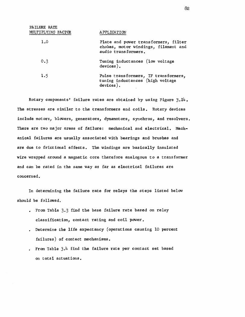
82
FAILURE RATE MULTIPLYING FACTOR APPLICATION
1.0 Plate and power transformers, filter chokes, motor windings, filament and audio transformers.
0.3 Tuning inductances (low voltage devices).
1.5 Pulse transformers, IF transformers, tuning inductances (high voltage devices).
Rotary components' failure rates are obtained by using Figure 3.14.
The stresses are similar to the transformers and coils. Rotary devices
include motors, blowers, generators, dynamotors, synchros, and resolvers.
There are two major areas of failure: mechanical and electrical. Mech-
anical failures are usually associated with bearings and brushes and
are due to frictional effects. The windings are basically insulated
wire wrapped around a magnetic core therefore analogous to a transformer
and can be rated in the same way as far as electrical failures are
concerned.
In determining the failure rate for relays the steps listed below
should be followed.
. From Table 3.3 find the base failure rate based on relay
classification, contact rating and coil power.
. Determine the life expectancy (operations causing 10 percent
failures) of contact mechanisms.
. From Table 3.4 find the failure rate per contact set based
on total actuations.

FIGURE 3.14 Failure Rates for Rotary Devices
83

84
. From circuit data calculate contact load in percent of rated
current. From Table 3.5 select the proper load factor and
multiply by failure rate found above.
• To obtain the final relay failure rate add contact sup-
plementary failure rates to the base failure rates.
TABLE 3.3 Relay Base Failure Rate
Relay Class Contact Rating Coil Power Base Failure
Rate
Sensitive 100 pa to 1.5 amp Less than 0.1 watt 400
General purpose 100 pa to 10 amp Above 0.1 watt 250
Power Above 10 amp * 40
Thermal 100 µa to 10 amp - 400
*In this class of relay, restrictions of coil power are not normal.
TABLE 3.4 Relay Failure Rates per Contact Set
Total Actuations for 90 Percent Survival Probability
100,000 18 35 53 70 88 105 123 140 158 175 90,00o 20 39 59 78 98 117 137 156 175 195 80,000 22 44 66 88 109 131 153 175 197 219 70,000 25 50 75 100 125 15o 175 200 225 250 60,000 29 58 88 117
146 175 2o4 233 263 292
50, 000 35 70 105 140 175 210 245 280 315 350 4o,000 44 88 131 175 219 262 306 350 394 437 30,000 58 117 175 233 292 350 408 466 515 583 20,000 88 175 262 35o 437 525 612 700 787 875 10,00o 175 350 525 700 875 1050 1225 1400 1575 1750

NOTES: 1. For manual switches, the chart applies directly.
2. For relays, apply chart and add the following supplementary failure rates:
Sensitive and thermal delay relays 400 General purpose relays 250 Power relays 40
3. Class differences:
Sensitive: Less than 100 milliwatts coil power General purpose: Contact rating of 10 amperes or less Power: Contact rating greater than 10 amperes
TABLE 3.5 Load Factor for Contact Current Rating*
Percent of Rated Current
Multiply By
Percent of Rated Current
Multiply By
100 1.00 4o 0.44 90 0.90 3o 0.36 80 0.80 20 0.30 70 0.70 10 0.25 60 0.61 dry circuit
**
50 0.52 (Not used) 0
*Proper arc suppression required.
**"Dry" circuit conditions (current less than 50 microamperes) constitutes a special case. If gold or paladium contacts are used, multiply by 1.0. Other contact materials in dry circuits are not recommended for general use.
Failure rates for low population parts are given in Table 3.6.
Reliability analysis can be classified into several different
categories. First, a reliability analysis can be made soon after the
design concept has been established by considering a rough estimate
of the system reliability. This estimate can be used as design goals
85

86
TABLE 3.6 Average Failure Rates for Low Population Parts
AVERAGE FAILURE RATE PART TYPE AND CLASSIFICATION IN FAILURES/105 HOURS
Accelerometers 1.0
Batteries 0.01/cell
Cells, Solar 0.001
Crystals, quartz (MIL-C-3098B) 0.0076
Gyros 5
Heaters (crystal oven) 0.01
Joints, solder (per connection) 0.00005
Microwave elements (coaxial and waveguide)
Elements, fixed Directional Couplers Fixed studs Cavities
Elements, variable Tuned cavities Tuned studs
Negligible (less than 0.001)
0.001 0.001
Loads Determine electrical Attenuators and temperature stresses
Fixed and use Figure 3.5 Variable
Thermistors 0.02
NOTE: These failure rates are applicable only if the parts are replaced before their respective wearout periods.

87
for future analysis. Next, a reliability analysis can be made as the
design becomes more definite as a result of a more accurate parts count.
The next category of reliability estimates is when the pre-production
and prototype units have been started to be built. An evaluation of
the reliability could then be made of this particular design showing
any weak areas that could be improved. A reliability estimate could
be made as a result of laboratory and/or field test data, thus giving
an estimate based on the test program. The last category could be a
reliability analysis by using actual test data of the unit in the
environment for which it is intended.
An example will be given to demonstrate the methods used in
obtaining a reliability prediction. The problem can be stated as
follows: A communication satellite system is to operate for one full
year in a synchronous orbit having a probability of success of 0.96.
What is the optimum configuration if the basic elements in the system
are as shown in Figure 3,15? The failure rates for each element
are shown in Table 3.7.
First all requirements must be defined. They are as follows:
a) The physical environment - Van Allen radiation belt, ambient
temperature, acceleration and vibration at launch.
b) Continuous operation of the communication satellite.
c) The satellite must operate without maintenance.
d) Burn-in of 200 hours of satellite before launch.

FIGURE 3.15 Basic Configuration of Communication Satellite
88

89
FAILURE RATES (X) BLOCKS FAILURES/105 HOURS
0.152
2 0.142
3 0.112
4 0.045
5 0.055
6 0.262
7 0.459
8 0.266
9 0.459
J 0.065
0.074
L 0.067
M 0.007
0.155
1 0.583
S2 0.148
TABLE 3.7 Failure Rates for Communication Satellite System

FIGURE 3.16 Redundant Configuration of Communication Satellite
90

91
PROBABILITY CONFIGURATION SYSTEM CONFIGURATION OF SUCCESS
1 (1.2.3.4.5.6.7.8.9.J.K.L.M.N) 0.637
2 [1.2.3.4.5.6.7.1LN] [any 5 out of 6 0.875 strings of (8.9.J.K.L]
3 [1.2.3.4.5.6.7.M.N.6s1] [any 5 out of 0.648 6 strings of (8.9.J.K.L)]
4 [1.2.3.4.5.6.7.M.N.6s2] [any 5 out of 0.810 6 strings of (8.9.J.K.L)]
5 [1.2.3.4.5.6.M.N•6S2] [any 1 out of 2 0.842 strings of (7)] [any 5 out of 6 strings of (8.9.J.K.L)
6 Same as configuration 5 except delete S2 0.897
7 Same as configuration 6 except add N 0.908
8 rAny 1 out of 2 strings {[1.2.3.4.5.6] 0.886 [any 1 out of 2 strings of (7)]
{[any 5 out of 6 strings of (8.9.3.K.L] [any 1 out of 2 strings of (N)]
[S1.S2.M] see Figure 3.16
9 Same as configuration 8 except delete 0.973 S1 and S2
TABLE 3.8 Different System Configurations for Satellite System Showing Probability f Success for One Year

92
e) Pressure, humidity, and temperature to be controlled.
f) Minimum power output to be used to provide longer life
of the satellite.
g) The frequency is to be specified.
The next step is to develop a reliability model. This is shown
in Figure 3.15 as a series string of elements. Then apply the
reliability data to the model and find out if the design requirements
have been met. Study various levels of redundancy so that the
requirement could be met.
By looking at Table 3.7, block 7 has the highest probability
of failure (highest failure rate). A way must be found to reduce
this failure rate. One way is to add another block 7 in parallel
redundancy as shown in Figure 3.16 along with other elements in
redundancy. Table 3.8 shows the reliability calculations for 9
different configurations.
It appears that configuration 9 is the optimum design. The
reliability calculations are shown below using the configuration as
shown in Figure 3.16 deleting S1 and S.
First calculate the reliability of branch A for six elements
functionally in series. The reliability is
RA =R1R2R3R4R5R6 1 2 3 5 6
RA = reliability of branch A
R1, R2'
. R6 = reliability of each element.

Since for a constant failure rate R = e-λt where λ is the
failure rate and t is the mission time the equation for RA becomes:
Since branch A is in series with branch B which consists of two
like elements "7" in parallel redundancy we must first calculate the
reliability of this redundant configuration. The reliability of
branch B is
The reliability of branches A and B is therefore
Branches C and D are identical to branches A and B respectively
and are in parallel redundancy. Either A and B or C and D must
operate. Therefore, the reliability of branches A and B or C and D is
93

Substituting the failure rates found in Table 3.7
Next calculate the probability of success for branch E or R2.
For one string of this branch
Now any 5 out of 6 strings must operate, therefore
Again substituting the failure rates found in Table 3.7
R2 = 0.97774
Now calculate the probability of success for elements M and N,
R3. For element M0
For element N one out of two must operate. The combined
probability of failure QN is equal to
94.

95
Substitute the failure rates found in Table 3.7
Now the reliability of the complete system is simply
Presented in this section was a way to perform reliability
predictions and estimates. Actually there are several techniques
that could be used. They will just be mentioned here for reference.
. Predictions based on typical equipment classification,
. Predictions using active element groups (AEG) count. .
Predictions by part count and nominal failure rate
assignment.
. Predictions by part count and assignment of failure rates
as a function of stress levels.
. Prediction methods based on MIL-R-26474, MIL-HDBK-217A,
NAV SHIPS 93820, RADC Reliability Notebook, and MIL-STD-756.
. Steady-state methods using algebra and matrix multiplication.
. Transient methods using Markov chain method and Markov
processes.
. Monte Carlo Techniques of simulation.
. Predictions by digital computer using the block diagram and
the probability of success for each block as the input (also
known as computer aided analysis).

. Predictions based on figure-of-merit (FOM) or amount of
experimental information received from the satellite while
in orbit.
. Predictions through determination and the adaptation of
complexity factor ratings.
These techniques while not precise are effective in reducing
failures and increasing system reliability and are therefore an
essential part in a reliability program such as this.
96

97
CHAPTER 4
SOLUTION TO THE PROBLEM
This chapter will delineate the following reliability tasks as
a continuation to the solution of the problem as stated in Chapter 3:
. Parts, Material and Process Control.
. Supplier Reliability Control.
• Failure Reporting and Analysis, and Corrective Action.
. Reliability Indoctrination and Training.
. Reliability Testing Program.
. Reliability Program Review.
Parts, Material, and Process Control
This task is essentially dealing with the reliability of parts,
materials, and processes in the communication satellite system. Part
failure modes and effects, mechanisms, and causes should be delineated
in detail along with those factors in material and processing that are
needed to assure a high degree of system reliability. It is the
responsibility of the reliability department to have overall cognizance
of this task. The department should supply necessary services to aid
in the selection of component parts, establishing a preferred parts
list, aid in the preparation of procurement specifications, analysis
of component part reliability data, take part in vendor evaluation, and
aid in reviews of a design and value analysis nature.
The preferred parts list should identify all parts by a detailed
procurement specification. This specification should include provisions

98
for reliability, quality control, and packaging. Component parts
needed for a system such as a communication satellite are obtained
by achievement of the following principles:
. Design the component part for the specific environment.
This includes choosing parts whose wear-out point is well
beyond the required useful life. Limitations on the life of
the component are effected by the space environment. The
environment is divided into the following five major effects:
magnetic fields, gravitational fields, vacuum, micrometeorites,
and radiation.
. Control of the manufacturing process. This includes control
on three phases of product life: a) prevent marginal product
from extending the period of early failures into the useful
life region (see Figure 3.4); b) assure lowest failure rate
during the useful life period; and, c) assure wear-out failures
do not occur in the region of useful life.
. Eliminate potential early failures by initiating screening
tests. This will include all forms of environmental testing
and operating tests under the expected conditions of the system.
Table 4.1 shows some typical screening conditions.
. Selection of most stable component parts as a result of the
extensive and intensive testing program.
The choice of component types should be selected on the following
basis:

MECHANICAL
Acceleration
Temperature/Humidity Cycle
Vibration (sinusoidal and random)
Shock
Radiographic inspection (x-ray)
Temperature cycle
RELIABILITY
Accelerated Tests
High Temperature processing
TABLE 4.1 Typical Screening Conditions
. Do not use new or untried types. This also applies to
materials used in the manufacturing of the components.
Use only those parts that have a sufficient background of
proven part performance.
. Adjustable components should be avoided due to severe
vibration, mechanical shock, and acceleration seen during
launch.
• Avoid use of hermetically sealed parts filled with oils or
electrolytes. These materials gas and build up very
destructive pressures under the severe radiation environment
seen in space. Materials for housing and structural use as
well as coatings should also be chosen carefully for resistance
to deterioration under electron and proton radiation.
99

. Such components as resistors, capacitors, and power trans-
formers, on which low pressure might have an effect were chosen
so that they would operate under extremely low pressure (vacuum
of space) without high temperature rise or other detrimental
effects encountered in space.
Table 4.2 shows the types of passive components used and their
typical uses for a communication satellite.
USE TYPE
CAPACITORS
General purpose, temperature compensation
Ceramic
Precision in low values Glass Precision in high values Mylar High values, small size Tantalum solid Precise tuning Glass and quartz
tubular trimmers
RESISTORS
General purpose, low precision Carbon composition General purpose, moderate
precision Pyrolytic carbon film
High precision, high frequency Metal film High precision Wire wound Power dissipation Vitreous enameled wire
wound
INDUCTORS
High frequency, general purpose (Nonmagnetic core, fixed) (Nonmagnetic slug, adjust-
able) Power frequency Permalloy dust core
toroid Memory coils Ferrite core
100

TRANSFORMERS
Narrow-band high frequency (tuned)
(Nonmagnetic core, adjust- able inductance)
(Magnetic core toroid)
Broadband high frequency (Closed ferrite core) (Ferrite cup core) (Laminated magnetic core)
Power frequency (Magnetic tape core toroid) (Permalloy dust core toroid)
TABLE 4.2 Types and Typical Uses of Communication Satellite Passive Components
One of the principles for selection of components was stated
as to design the component for the specific environment because of
the limitations of useful life imposed on the components due to the
space environment. Delineated below are definitions of the major
space environmental effects.
Magnetic fields - The earth's magnetic field at the magnetic
equator has a maximum horizontal flux component of 0.3 gauss. It is
presumed that this field varies inversely as the cube of the distance
from the center of the earth. As the distance increases, the earth's
magnetic field becomes irregular, probably due to reaction with the
magnetic component of the solar wind and plasma clouds. The magnetic
flux densities of the order of magnitude found in the space environ-
ment will not have any noticeable affect on the mechanical properties
of materials. However, sensitive meter movements and other devices
which operate with low magnetic flux densities are affected.
101.

102
Gravitational fields - The acceleration of gravity, g, may be
calculated at any altitude, h, above the earth's surface by the equation
where ro is the radius of the earth, and g is the acceleration of
gravity at a distance ro from the center of the earth. The absence
or reduction of the force produced by the earth's gravitational field,
while having no affect upon electronic components or equipment, may
have an appreciable affect on the operation of certain mechanical or
electromechanical systems. For manned space flights, the physiological
effects would require the greatest amount of consideration.
Vacuum - The gas pressure in space is extremely low and measuring
it is not feasible at the present time. Generally, the pressure at
various altitudes is determined by calculations based on the ideal gas
law and values of pressure at low altitudes where direct measurement
is possible. Latest models of the atmosphere indicate approximate
pressures of 10-5 mm mercury at 100 miles altitude and 6 x 10-11 mm
mercury at 1000 miles. It is estimated that the pressure outside the
solar system may be as low as 10-16 mm mercury.
Low atmospheric pressure sublimates solids and evaporates liquids.
Sublimation of metals may result in the condensation of these metals on
electrical contacts and terminals causing arcing and short circuits.
Plasticizers with high vapor pressures (used in many plastic materials)

103
may lose a great deal of mass due to evaporation, with resulting
changes in structural properties. Moving metal parts operating in
direct contact will lose their oxide coating, and in the vacuum of
space these coatings will not re-form. Uncontaminated metal surfaces
in direct contact may gall and seize.
Micrometeorites- a Micrometeorites are small particles of matter
existing in outer space. They are considered to be debris from other
bodies in the solar system. These particles are considerably larger
than molecular size, and, generally are approximately a few microns in
diameter. Most of these particles are thought to be of cometary origin,
although some are believed to be fragments of asteroids. The velocity
of the particles relative to the earth varies from about 11 to 72
kilometers per second; however, accurate data concerning the density
and mass of the particles and the number of particles impinging per
unit area per unit time of a given mass are not available. The
impingment of micrometeorites upon any solid surface will result in
sputtering, erosion, and a general roughening of the surface. This
change of surface characteristic will have its greatest affect on the
thermal and optical properties of materials.
Radiation - Radiation is defined as the combined processes of
emission, transmission, and absorbtion of radiant energy. Radiant
energy is composed of particle radiation and electromagnetic radiation
and consists of the following:

Particle radiation
Electrons
Protons
Neutrons
Alpha particles
Electromagnetic radiation
X rays
Gamma rays (photons)
The penetrating radiation environment of space may be due to a
variety of sources, the most important of which follow:
Cosmic radiation
Trapped radiation
Auroral radiation
Solar flare radiation
The effects of the space environment on electronic components
that would be used in communication satellites are listed below.
Semiconductor devices - The relatively low radiation tolerance
of semiconductor devices sets them apart from other electronic components.
With few exceptions, most transistors fail completely when subjected to
an integrated dose of approximately 1013 neutrons/cm2 and 107 roentgens
gamma radiation. Significant differences have been conclusively
observed between the behavior of germanium and silicon transistors in

105
radiation fields, with germanium showing slightly more radiation
resistance than silicon. Semiconductor diodes exhibit a greater
neutron tolerance than do transistors; however, the gamma tolerance
is about the same. Infrared detectors (PbS cells) have been tested
at 1012
neutrons/cm2
and 106
roentgens gamma radiation and were found
to operate satisfactorily after irradiation. However, like most other
semiconductor devices, permanent damage was clearly evident when these
dose rates were increased by a factor of ten. Thermistors, which are
also semiconductor devices, have been reported to survive an integrated
dose of 1013
neutrons/cm2
and 106
roentgens gamma radiation. The
useful life of a semiconductor device in a radiation field will depend
on the circuit application or function required. Failure because of
radiation does not usually appear as a sudden or abrupt change but
rather a gradual change in characteristics. The following character-
istics have been noted in the irradiation of semiconductor devices.
Transistors - Gamma radiation may cause permanent as well as
temporary degradation if the total exposure becomes high enough.
Current gain is decreased. Germanium devices are less sensitive to
damage than silicon devices. Diffused-junction structures are less
sensitive than alloyed-junction types.
Diodes - Not affected to the same extent as transistors. Thin
based-width devices are less sensitive than thick based width devices.
Forward voltage at constant current increases and reverse resistance

decreases, Diffused-junction structures are less sensitive than
alloyed-junction structures. Germanium devices are less sensitive
than silicon devices.
Controlled Rectifiers - Data available indicates that these units
can be used in a radiation environment of integrated fast-neutron flux
on the order of 1014 neutron/cm2
Failures experienced are not catastrophic in nature but result
from the increase in gate current required to fire until the gate-
cathode junction heating becomes excessive,
Capacitors - Capacitors that use inorganic materials, such as
glass, mica, and ceramic have exhibited the greatest resistance to
radiation. Organic dielectric capacitors, polystyrene, polyethylene,
and mylar are less satisfactory than the inorganics by about a factor
of ten; however, they do offer a better capacitance-to-volume ratio.
Paper - A 20 to 30 percent change in capacitance and minor
changes in dissipation factor can be expected when exposed to a
radiation of fast-neutron flux of 1015
n/cm2 and gamma exposure of
3 x 10⁸
roentgens. The combined effect of pressure build-up by
high temperatures and radiation and the evaporation of the solder
material used in the seal due to high vacuum could accelerate a
failure condition.
106

107
Ceramic - Available data for all types of ceramic capacitors
indicates that no extensive degradation of electrical and physical
characteristics can be expected from a fast-neutron flux of 2 x 10¹⁵
- n/cm 2 nd gamma exposure of 3 x 10
8 roentgens. However, it is
believed, that other environments such as ambient temperature and
high vacuum may be more important for design considerations.
Glass and Porcelain - The threshold of radiation damage has
been estimated to be 105
n/cm- fast-neutron flux and a gamma exposure
of 109 roentgens. These types show more resistance to nuclear radiation
than others; however, the effect of ambient temperature and high vacuum
may be more important.
Plastic - When this type of capacitor is irradiated in a fast-
neutron flux of 1015
n/cm-2
and a gamma exposure of 3 x 10⁸
roentgens
a 10 to 11J percent change in capacitance and a 3 percent change in
dissipation factor can be expected. Teflon is not recommended as
a dielectric, regardless of whether it is immersed in silicone oil.
The limited information that is available concerning life expectancy
and reactions to ionizing radiation fluxes indicates that polystyrene
dielectric units will not perform satisfactorily. Existing data
indicates that a mylar capacitor would perform better.
-2 Mica - When exposed to a fast-neutron flux of 10
15 n/cm and
gamma energy of 3 x 10⁸
roentgens a capacity decrease of approximately

108
5 percent or less can be expected. However, the reliability of mica
capacitors is approaching the level of ceramic and glass capacitors.
Tantalum - Solid electrolyte tantalum capacitors are not expected
to be impaired to any great extent in a combined environment of 100°C
ambient temperature, high vacuum, and radiation levels of 5 x 10¹³
of cm-2 fast-neutron flux, and 7 x 10⁸ roentgens gamma energy. The
wet-foil tantalum capacitor has the same characteristics as the wet-slug
tantalum capacitor and appears to be ideal for use in a high ambient
temperature. Further study is required to determine the effects of
nuclear radiation and high vacuum. Teflon is definitely not
recommended for sealing purposes.
Mylar - There is very little information available concerning
effects of radiation, temperature, and high vacuum on the reliability
of mylar capacitors; however, some advantages may be gained in place
of paper capacitors. The effects of exposure to high vacuum would
depend to a great extent on the quality of the glass seal.
Oil impregnated - A 30 percent increase in capacitance and an
increase in the dissipation factor can be expected in a radiation
environment of fast-neutron flux of 1015
n/cm-2 and gamma energy of
5 x 10⁸
roentgens.
Connectors (Miniature) - The construction materials of
connectors will determine their susceptibility to the effects of a

109
combined environment of radiation, high vacuum, and temperature.
Elastomeric inserts, nylon boots, epoxy potting compounds, and
compression glass-seal receptacles are organic materials which react
unfavorably. When used in a high-vacuum environment, consideration
must be given to the terminal spacing and the effect of corona
ignition and extinction voltages.
(Subminiature) - The same considerations as outlined above for
miniature connectors apply; except that the effect of the reduced
terminal spacing will present a greater design problem.
Relays (Miniature and Subminiature) - The materials of construction
will determine the reliability of relays in a combined space environment.
Hermetically sealed units would be unsuitable for use in a high vacuum
in view of the difficulties experienced with epoxy sealants. Since
contact clearances are relatively small, corona ignition and extinction
should also be considered.
Inductors - The available information is incomplete to provide
a reasonable estimate of the reliability of inductors in a combined
space environment. However, the information that is available indicates
that various inductors will remain reliable in a fast-neutron flux of
1 10
4 n/cm
-2 and gamma energy of 10
10 roentgens.
Transformers - The threshold of radiation damage to transformers
is high in comparison to the effects on other components and materials.

110
The high-temperature environment imposes rigid requirements that
preclude many insulation materials used in conventional transformers.
The problem of high-vacuum effect and material diffusion should be
given consideration.
Resistors (Metal-Film) - In the construction of metal-film
resistors, the film is deposited on the outer surface of a steatite
tube and molded solid in a high-temperature plastic such as diallyl
phthalate. As such, excellent reliability can be expected when
exposed to an environment of high temperature and radiation. However,
some units are constructed by depositing the film on the inner surface
of a steatite tube and it appears that damage could be expected due to
ionization of the trapped air.
Carbon-Film - Basically similar in construction to metal-film
resistors but differs mainly in resistive element materials. Because
of the carbon-film, degradation becomes more a function of temperature.
Carbon-film resistors are generally more sensitive to exposure than
metal-film resistors. The effects of high vacuum on carbon-film
resistors have not been thoroughly explored; however, a study of the
basic materials indicate a better performance could be expected from
metal-film resistors.
Carbon Composition - This type of resistor is considered to be
more susceptable to radiation damage than carbon-film. The threshold
of radiation at which significant changes in resistance occur have
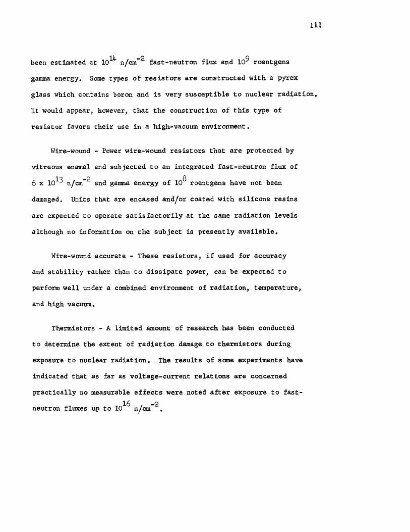
111
been estimated at 1014 n/cm-2 fast-neutron flux and 109 roentgens
gamma energy. Some types of resistors are constructed with a pyrex
glass which contains boron and is very susceptible to nuclear radiation.
It would appear, however, that the construction of this type of
resistor favors their use in a high-vacuum environment.
Wire-wound - Power wire-wound resistors that are protected by
vitreous enamel and subjected to an integrated fast-neutron flux of
6 x 10¹³ n/cm-2 and gamma energy of 10
8 roentgens have not been
damaged. Units that are encased and/or coated with silicone resins
are expected to operate satisfactorily at the same radiation levels
although no information on the subject is presently available.
Wire-wound accurate - These resistors, if used for accuracy
and stability rather than to dissipate power, can be expected to
perform well under a combined environment of radiation, temperature,
and high vacuum.
Thermistors - A limited amount of research has been conducted
to determine the extent of radiation damage to thermistors during
exposure to nuclear radiation. The results of some experiments have
indicated that as far as voltage-current relations are concerned
practically no measurable effects were noted after exposure to fast-
neutron fluxes up to 1016
n/cm-2.

112
Varistors - Information concerning the effect of radiation on
varistors or voltage-sensitive elements is not available. However,
since most of the varistors currently used are selenium or copper-
oxide rectifiers, information of these elements can be substituted.
In general, the semiconductor types of varistors can withstand nuclear
radiation up to 1014 TV=
-2 without serious changes in their forward
or reverse characteristics. Diodes fabricated from silicon carbide
were found to be most radiation resistant, and it is hypothesized that
these elements hold great promise for use in nuclear environments up
17 -2 to total integrated exposures of 10 n/cm
Sensitive Microswitches - On the basis of available data it
appears that the inorganic materials of which microswitches are con-
structed would not be seriously affected by nuclear radiation. However,
the organic materials would be degraded in a vacuum where sublimation
and evaporation would occur and the threshold of gamma radiation is
estimated to be approximately 1010
roentgens. It is believed that a
greater assurance of good performance in a combined environment will
be achieved provided the organic materials used for insulation and
plungers are fabricated from synthetic mica. Consideration should
also be given to the corona ignition and extinction voltages when
operated in a high vacuum.
Thermostats - An examination of the basic construction materials
from the point of view of radiation tolerance does not indicate rapid
deterioration. Little information is available on the effects of high

vacuum; however, it is believed that if thermostats with silver
contacts are required to interrupt a reactive load, the metal spray
may reach prohibitive proportions. Palladium or platinum should be
considered for such applications.
Coaxial Cables and Wire - Coaxial cables containing the poly.
ethylene dielectric materials are believed to be satisfactory for
the combined environment of 100°C temperature, high vacuum, and nuclear
radiation. In a radiation environment above 1010
roentgens of gamma
energy the polyvinyl chloride jacket will become hard and decrease in
flexing capability. At high radiation levels and operation at high
radio frequencies a slight increase in dielectric constant and a
decrease in characteristic impedance can be expected. It is not
considered advisable to use teflon dielectric cables because of their
poor performance in a nuclear radiation and high-vacuum environment.
It has been strongly recommended by most system application and design
engineers that polyethylene-insulated hook-up wire be used wherever
a combined environment is anticipated.
Electron Tubes - These components fail when exposed to high-
intensity radiation fields due to damage to the glass envelope or
glass-to-metal seals. Boron-free glasses show more resistance to
radiation damage and can withstand integrated mixed fluxes as high as
18 -2 10 n/cm-2 ; however, there are indications that an increase in
fragility can be expected which might shorten the life of an
113

114
electronic device. The envelopes of subminiature and miniature
vacuum tubes exhibit more resistance to nuclear damage than other
glass-type tubes. This is mainly due to the reduction in bulk of
the glass envelope and the size of metal-to-glass seals.
The correct operation of gas tubes depends on maintenance of
proper potentials and voltage drops across the tubes. The elements
normally used in gas tubes react to nuclear bombardment in a manner
similar to that encountered in vacuum-tube elements. The major cause
of malfunction for gas tubes, excluding damage to glass-envelopes, is
related to radiation effects on the gas. The gas is affected by gamma
ionization and proton recoil ionization which often cause structural
transmutation.
Gamma radiation of 1010
roentgens causes appreciable physical
damage only to electron tubes that depend for their main function
upon light transmission through the envelope. Discoloration of glass
greatly affects the operation of light-sensing devices. Radiation-
induced currents have been detected and these currents frequently exceed
the photomultiplier's rated current. Tube sensitivities are greatly
affected and can be attributed to glass discoloration.
The use of magnetrons in a nuclear environment is limited by
radiation damage to the glass-to-metal seals used in their construction.
In applications involving ultra-high frequency principles, the dielectric
constant of the various insulating materials greatly influences the
operational characteristics.

115
If nuclear damage results in complete failure as would be
encountered when the glass envelope of a tube fails, there is no
point in considering the changes that occur in electrical operating
characteristics. However, electrical changes, such as decreases in
plate current, reduction of emission current, increases in control
grid current, and changes in transconductance are design considerations.
Coatings - The interest in coatings is a result of the need to
develop more stable temperature-control coatings for satellites and
space vehicles. Additives such as pigments, plasticizers, and other
coating ingredients, as well as the type of surface on which the
coating is applied, influences the radiation resistance of the coating.
Table )4.3 gives radiation resistance of some coatings.
COATING GAMMA RADIATION RESISTANCE
Phenolic 5 x 10⁹ roentgens
Silicone-Alkyd 1-5 x 10⁹ roentgens
Alkyd Enamels
40% Phthalic Anhydride (MIL-D-5557) 1-5 x 10⁹ roentgens
32% Phthalic Anhydride 8 (MIL-E-7729) 7-10 x 10 roentgens
Epoxy 5-10 x 108 roentgens
Fluorinated Vinyl 5-10 x 108 roentgens
Nitrocellulose Lacquers 5-7 x 10⁸
roentgens
TABLE 4.3 Limits of Radiation Resistance of Selected Organic Coatings

116
The reliable application of component parts, materials, and
process control in space application such as a communication satellite
system, shows a present capability of withstanding the effects of space
environment. As more sophisticated space missions are encountered for
extended useful missions, more stringent requirements will be placed
on the reliability of components and materials used in the space
environment.
Supplier Reliability Control
This program task includes controlling vendor and subcontractor
activities to assure their capability of furnishing components having
the required reliability requirements. Some of the specific tasks
included under this phase of the program are:
. Supplier plant surveys
• Supplier rating systems
. Requiring suppliers to prepare written reliability program
plans.
Reliability personnel have the responsibility for the surveillance
of the supplier reliability performance in the design and manufacturing
of the end item. This surveillance is continued by participation in
all design reviews at the supplier's facility and reviewing all
activities that will have an impact on reliability.
In order to perform an effective and timely supplier evaluation
many factors come into play. Of prime consideration are the following:
117
. The supplier should have a well defined manufacturing setup,
readily adaptable to fabrication of the high reliable product.
. The supplier should have adequate personnel who are technically
knowledgeable in designing, manufacturing and testing the product
in accordance with the high reliability standards and specifica-
tions necessary for end product reliability integration.
. The supplier should have adequate capacity for manufacturing
and testing the product without the danger of slippage in
delivery schedule.
. The supplier should be able to supply sufficient test data,
particularly life test and field test results, verifying the
product's capabilities or limitations, and therefore enabling
the criteria for failure rates.
The supplier, in addition to the above considerations, must be
willing to participate in a high reliability program financially. This
will enhance his future programs in the space area as he becomes a
qualified supplier for space environmental projects.
The supplier rating system is a very useful tool to aid purchasing
in maintaining and upgrading the quality of the product delivered from
the supplier. As an example of the rating system let's consider the
following: A rating of 75 would occur when the sample fraction
defectives are equal to the specified acceptable quality level (AQL),
with a maximum of 1 in 25 lots rejected. A rating of 60 would occur

118
when the sample fraction defectives equal 0.5 times the specified
AQL's, with a maximum of 1 in 156 lots rejected. The AQL is defined
as a nominal value expressed in terms of percent defective or defects
per hundred units for a given group of defects of a product.
The supplier's reliability program plan that is required by the
prime contractor should include those items necessary for manufacturing
the item so as to meet all of the high reliability requirements. It
should include but not be limited to the following tasks.
Design Reviews - held at supplier's facility with the
responsible prime contractor personnel present.
Production Control - to assure that the reliability achieved in
design is maintained during manufacture.
Reliability Test Program - tests should be designed to give
confidence in the end item to meet expected environments.
Reliability Analysis - made on a periodic basis of reliability
achievement of the technical progress evaluations.
Failure Reporting, Analysis, and Feedback - formalize a system
for reporting, analyzing, and recommending corrective actions on all
failures.
Reliability Monitoring - to insure adequate development of
reliability by analyzing the reliability status relative to the

119
requirements; by determining the corrective action needs; and by
setting up a follow-up procedure on all corrective actions initiated.
Only through a tight supplier reliability control program will
the assurance be given that the items received from that supplier are
indeed those items needed for a successful completion of the proposed
mission. For a mission such as communications by satellite for periods
in excess of 3 to 5 years, this task cannot be overemphasized enough.
Failure Reporting, Analysis, and Corrective Action
This next phase of the program plan is an integral part of the
reliability effort for spacecraft systems. Although successful
operation of the complete system is the ultimate goal that is sought,
it adds very little feedback and information on which design improve-
ments can be made. If failures are encountered during manufacturing or
qualification, acceptance, or reliability testing, these add much data
necessary for an effort of improvement to the design. This feedback
information of failure reporting, failure analysis, and corrective
action is one of the essential ingredients of reliable product
improvement.
The failure reporting phase of this task should provide a closed
loop system that is well monitored. It should report all failures on a
timely basis so that failure analysis can be performed quickly, defining
the cause of failure. As a result of the analysis, corrective action
is instituted to assure against this type of failure recurring on

120
the system. Time is of the utmost importance in performing this task
so as to implement necessary changes or rework on the system, thus
increasing the probability of a more reliable system.
A well formulated failure reporting system should have failure
history records. These records serve two main purposes. First, the
chances of the same problems occurring in future systems are minimized.
(Solutions already obtained from part system failures should be in-
corporated into design review checklists as outlined in Figure 3.1
under the task of Reliability Design Reviews). Second, an estimate
of the reliability of the new system can be made realistically. For
example, actual failure rates obtained under field or use conditions
could be used in predicting or estimating the system reliability of
similar units.
The failure reporting system should provide the following infor-
mation as a minimum:
. Component description, type
. Serial number
. Date entered production
. Circuit reference number
. Operational test time
. Cumulative operational test time
. On-off cycles
. Cumulative on-off cycles
. Serial numbers of next higher assembly

121
. Part number and serial number of components
. Description of failure
. Corrective action initiated and due date
There are many types of failure reporting forms in use today.
The features of some of these are described below:
. Development Form. This gives detailed reporting of the
failure that is at system detection, unit rework, and part
failure analysis levels. This form is basically useful for
low volume, detailed analysis, and manual data processing.
. Flight Test Form. Similar to the development form for
specialized subsystem field flight use. It is not as
detailed in coverage as the development form but is suitable
for low volume manual data processing.
. Production Reliability Test Form. Specifically set up for
reliability test failure reporting. This form features
numerous combinations of cause-of-failure codes. Also
corrective action follow-up is provided for timely feedback.
. Field Failure Report Form. Designed for high volume military
reporting where machine data processing is essential. One form
is used per failure.
. Industry Electronic Field Failure Report. This form classifies
type of failure at system, subsystem, unit, and part levels.
The type of failure code is stated on each form. Also field
and supplier repairs and replacements could be documented on
each form generated.

122
To simplify failure reporting a coding system should be set up
and utilized. One such system could use a coding category as follows:
. Parts classification code
. Manufacturer's code
. Part condition code
. Symptom code
. Mode of operation code
. Environment code
. Corrective action code
. Cause of failure code
. Responsibility code
A failure analysis system is an essential part of the task and
requires the reporting of all failures occurring during system
production. Of primary interest during failure analysis are the
following:
. The failure cause should be identified for proper analysis
and corrective action.
. Determine overstress on other components due to the primary
failure and to find out the effects of the overstress.
. Initiate repair of failure and corrective action as necessary.
All failure analysis should take into account the following
procedures:
. Appropriate system specifications and test data should be
reviewed.

123
. Physical examination of the failed unit should be made before
proceeding with failure analysis. Visual evidence will save
time before analysis begins.
. A verification of the reported failure should be made as soon
as practical.
. If necessary, extended tests should be made, such as radio-
graphic and/or infra-red.
. The piece part should be dissected for further analysis if
deemed necessary. Photographs or drawings should be prepared
for clarification of the analysis.
. Mode of failure should be determined at this point in time and
corrective action recommended.
The information requested for each failure analysis should
include enough information for a complete description of the failure
and corrective action. As a minimum the following is required:
. Failure analysis report number
. Failed part description
. Program name
. Date of failure
. Major system and serial number
. Major subsystem, serial number, and drawing number
. Major module and serial number, drawing number and manufacturer
. Failure verified/not verified
. Lot quantity

. Department reporting failure
. Classification of failure (critical, major, minor)
. Failed part environment (temperature, humidity, etc.)
. Description of failure
• Photographs and radiograph, file number, if any
. Name of personnel preparing form and date
. Name of personnel approving form and date
. Corrective action instituted and date
. Tests performed to confirm failure
. Failure analysis
. Corrective action and recommendations made.
A flow diagram of a failure reporting, analysis, and corrective
action system is shown in Figure 4.1.
The depth of failure analysis could vary from somewhat trivial
to a sophisticated and detailed one. During the period of a high
reliability program such as the communication satellite system, many
failures might occur which need to be analyzed, and corrective action
implemented as required. Therefore, a well organized program is required
to implement a failure reporting, analysis, and corrective action task
on a timely basis.
Reliability Indoctrination and Training
The reliability of the communication satellite system will be
enhanced if a comprehensive training and indoctrination program is

FIGURE 4,1 Summary of Flow Failure Reporting, Analysis & Corrective Action System
125

126
initiated early in the program. Each functional group such as
design engineering, production, procurement, quality control, and
test engineering will contribute greatly to the reliability of the
satellite system if each group knows the nature of its contribution
and is so motivated to carry it out. The indoctrination and training
program could consist of lectures, motion pictures, periodic bulletins,
posters and displays, and a reliability training manual. Regardless
of what method is used and training program is a continuing education
process.
The implementation of a reliability training program is based
on many factors which are delineated below.
First, who should be told about the importance of reliability
and its effects on long-life systems such as a communication satellite?
Every branch of the organization responsible for an effort in the high
reliability requirements of the system should be made aware of the
principles and practices of reliability fundamentals. Remember, it
will be easier for a group to accept something new and helpful only
if the group has a full understanding of the basic problem and an
insight to its solution. A proper training program will make each
group aware of the need, the methods, and the effect on themselves
and their jobs.
Secondly, why start a reliability training program? Basically,
the reason is to develop an understanding of, and a desire to, achieve

the fundamentals of reliability. There are many more reasons for
starting a training program. They can be summarized as follows:
. To make groups aware of the meaning and important signifi-
cance of reliability and methods for its control.
. To make known to management the problems others are faced
with in attempting to achieve a high level of reliability.
. To emphasize the differences between short term and long
term program goals, as far as the achievement of reliability
is concerned.
. To aid design personnel in diagnosing system and design
problems. This can be worked in conjunction with the
reliability design review task previously discussed.
. To unify the entire organization into a team to achieve the
goals set up in the reliability program.
Thirdly, the question of what should be taught in the training
programs must be answered. This depends on what level in the organ-
ization the training program is given. For top management personnel,
the program should show the accomplishment of improving the company
profit, reducing manufacturing costs, saving time, keeping up with
schedule objectives and goals, and improving the customer-seller
relationship. Top management is not interested primarily in the
technical aspects of the program, but rather in the economic and
financial phases. Middle management training courses should help
127
128
the group in performing better on the job, supply them with new
techniques to aid their advancement, defining their responsibilities
in the program for achieving the reliability objectives, help reduce
costs and meet schedules better, and help in training their subordinates.
The middle management personnel will understand the technical problems
far better than top management personnel. Members of the technical
staff such as design, industrial, production, and laboratory engineers
should be trained emphasizing the following:
. The technical, scientific and mathematical techniques to
solve problems as encountered in reliability.
. All the fine points and details with alternatives should be
presented depending on the group taking the training.
. Need for simplification of technical ideas when communicating
with higher management who are not well versed in the technical
aspects of the program.
The training and indoctrination classes for the operating per-
sonnel, which includes manufacturing, assembly, inspection and test
groups, should stress the following points:
. Those opportunities which will be available after working
on a high reliability satellite program.
. Simplification of the job as a result of the training program.
. Contribution of the training program to the job security.

129
Sophisticated technical language should be avoided, if possible,
when presenting a topic. Moreover, when it is feasible, calculations
should be simplified utilizing well known mathematical procedures.
For a high reliability program such as the one for the communi-
cation satellite, training and indoctrination plans should be developed
for the different levels of the organization involved. The following
plans are presented as illustrative of what should be covered at the
different organizational levels and the approximate time needed.
For top management, the course should run for 8 to 10 hours
spread out over 4 or 5 weeks (this is equivalent to one day per week
for 2 hours per class). The general plan should cover the following
subjects:
. Need for the training program.
. Principles of reliability.
. Typical class problems and solutions.
• Program organization.
The middle management personnel course should run for approx-
imately 12 to 16 hours spread out over 6 or 8 weeks (this is equivalent
to 2 days per week for one hour per class). The general plan should
cover the same subjects as for top management only in more detail,
especially the principles of reliability and class problems.
The staff technical course should run for 20 to 40 hours spread
over 10 or 20 weeks (this is equivalent to 2 days per week for one hour
per class). The plan should include the following reliability
disciplines:

130
. Need for the training program.
. Principles of reliability.
. Theory, methods, techniques, and class problems.
. Program organization.
For the operating personnel the training program should run for
8 hours spread over 4 weeks (this is equivalent to 1 day per week for
2 hours per class). The topics should include the need for a training
program, general principles of reliability, and how the program will
affect each one on the job.
The classroom meetings could be supplemented by other techniques
such as visual aids, blackboard work, charts, recordings, trips, plant
tours, and training film. Training films seem to be most effective. The
following is a partial list of films having a bearing on reliability that
should be shown to the personnel working on high reliability programs.
• "The Search for Reliability" - Standard Pressed Steel Co. -
Primarily treats of fastener reliability and highlights the
product rule. Standard Pressed Steel Co., Jenkintown, Pa.
• "The Art of Soldering" - Boeing Airplane Co. - Reliability
improvement through correct soldering techniques for printed
circuits. Boeing Airplane Co., Seattle, Washington.
• "10-9-8 Hold" - Boeing Airplane Co. - The abortion of a
Bomark interceptor mission resulting from a single solder
connection failure. - Boeing. Airplane Co., Seattle, Washington.

131
• "Tremendous Trifles" (Confidential) - Lockheed Aircraft Corp. -
The high cost of poor workmanship and quality control. - Space
Technology Laboratories, Los Angeles, California.
• "The Closed Loop of Reliability" - Martin Co. - The need for
failure reporting accuracy and an approach by the Martin Co.,
Denver. - Space Technology Laboratories, Los Angeles, California.
• "Talos, Deadly Where Reliable" (Confidential) - Bendix Aviation -
The importance of superior workmanship standards as an approach
to reliability. - Chief, Technical Publications, Bendix Products
Division - Missiles, Bendix Aviation Corp., Mishawaka, Indiana.
• "Talos, Flight 440" (Confidential) - Bendix Aviation - A true case
history of a flight failure. - Chief, Technical Publications, Bendix
Products Division - Missiles, Bendix Aviation Corp., Mishawaka,
Indiana.
• "Rascal Project MX-776" (Confidential) - Bell Aircraft Corp. -
Flight tests, both successful and unsuccessful, of the Rascal
weapon system - Bell Aircraft Corp., Manager, Photographic Dept.,
Buffalo 5, New York.
. "No Margin for Error" - Bell Aircraft Corp. - Designed for
production workers, showing importance of each worker's contribution
to overall system reliability. - Bell Aircraft Corp., Manager,
Photographic Dept., Buffalo 5, New York.
• "No Second Chance" - The story of how one weapon system - an
interceptor missile - has been made reliable. - Air Force Film
Library Center, Air Photographic - Charter Service, St. Louis 25,
Mo. - Film #D0-59-41SEP456.

132
• "A Life in Your Hands" - Hughes Aircraft Co. - The importance
of the indivual component part in a failure that caused a
mission abort. - Public Relations & Advertising, Hughes Air-
craft Co., Culver City, California.
• "The Prime Dimension" - Hughes Aircraft Co. - How a modern
weapon producing organization engineers and builds reliability
into its product. - Public Relations & Advertising, Hughes
Aircraft Co., Culver City, California.
. "A Synthesis of Standards" - Convair - The importance of
standards and the strict adherence thereto as a means of obtaining
high reliability. - Convair Division of General Dynamics, Pomona,
California.
• "The Price of a Goof" - Redstone Arsenal - The failure of a
missile flight is traced from a solder joint to the abort. -
U. S. Army Ordnance District, Dallas Regional Office, Dallas 2,
Texas.
• "The Priceless Component" - Hughes Aircraft Co. - The importance
of the individual component parts to quality and reliability. -
Public Relations Department., Hughes Aircraft Co., Culver City,
California.
Reliability Testing Program
Reliability of the communication satellite system is an attribute
that must be designed into it. As stated previously, reliability cannot
be tested into the system, but rather testing could be used to evaluate

133
the design. Testing could be considered a design tool to find and
eliminate the weak areas in the satellite system and thereby upgrade
its quality. Reliability testing is necessary for the following
reasons:
. To verify that the design meets the performance requirements
and has the required life expectancy.
. To verify that hardware used previously is suitable in the
new application.
. Detecting and correcting failure modes as a result of the
tests performed.
. Monitoring reliability trends and evaluating the results of
any changes.
. Train personnel who will be responsible for the system during
its launch and for data analysis and reduction.
The environments that the satellite will encounter could be
stated as: (a) prelaunch; (b) launch; and, (c) orbit. The environ-
mental conditions experienced by the communication satellite are shown
in Table 4.4.
PRELAUNCH LAUNCH ORBIT
. Temperature & . Shock & Vibration . Space Vacuum
Humidity . Acceleration-Thurst, . Solar Radiation
. Shock & Vibration Guidance, Wind Shear . 3°K Heat Sink
. Handling . Aerodynamic Noise . Earth Radiation
. Sterilization . Aerodynamic Heating and Albedo
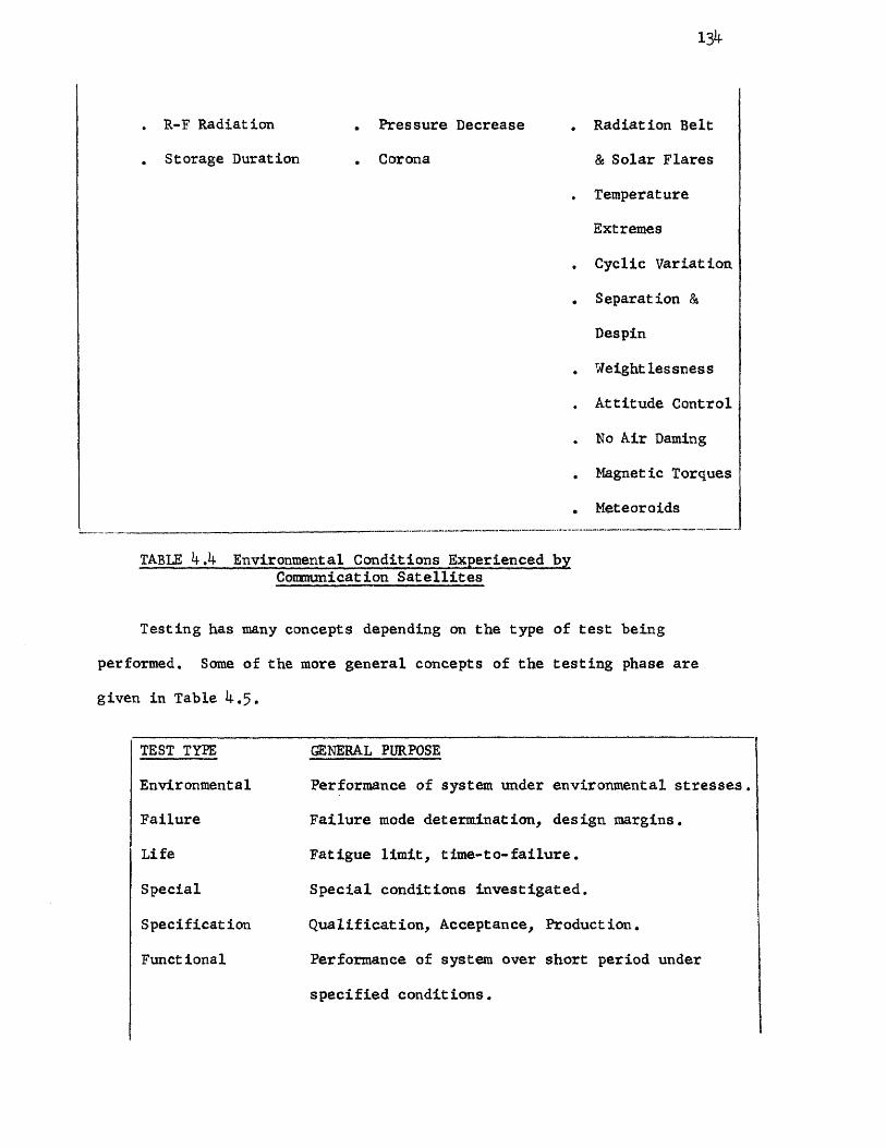
1.34
• R-F Radiation Pressure Decrease . Radiation Belt
. Storage Duration . Corona & Solar Flares
. Temperature
Extremes
. Cyclic Variation
. Separation &
Despin
. Weightlessness
. Attitude Control
. No Air Darning
. Magnetic Torques
. Meteoroids
TABLE 4.4 Environmental Conditions Experienced by Communication Satellites
Testing has many concepts depending on the type of test being
performed. Some of the more general concepts of the testing phase are
given in Table 4.5.
TEST TYPE GENERAL PURPOSE
Environmental Performance of system under environmental stresses.
Failure Failure mode determination, design margins.
Life Fatigue limit, time-to-failure.
Special Special conditions investigated.
Specification Qualification, Acceptance, Production.
Functional Performance of system over short period under
specified conditions.

135
Reliability Performance of system for a specified time
under specified environmental conditions.
TABLE 4.5 Concepts of Testing
For the communication satellite system all parts will be elec-
trically and environmentally tested. All critical items used in the
system will be screened for parameter drift. The high reliability
testing program to be performed for the various components will now be
delineated. The specific environments and various testing parameters
are given in Table 4.6.
Semiconductors - All parts to be burned-in for 1000 hours at
maximum power.
Electrical parameter drift measurements to be performed on all
components, before, during, and after burn-in. For transistors,
collector-base cutoff current, and DC current transfer ratio are
measured. Measurements of emitter-base cutoff current, collector-
emitter saturation voltage, and a breakdown voltage parameter are
required. For diodes, leakage, forward voltage, and breakdown voltage
are to be screened.
Samples from each type are subjected to environmental, life,
and temperature cycling tests in accordance with the applicable
component specification.

Mechanical & electrical Characteristics Terminal Strength
Shock Vibration
Temperature Cycling Immersion Cycling
Dielectric Strength Moisture Resistance
Temperaure Coefficient Corrosion
High Vacuum
Resistance to Sildering Heat Low Temperature Operation
Short Term Overload Solderability High and/or Low Temperature Storage
Aging
Thermal Shock
Acceleration
Phase Jitter
Seal
Resistance After
Overload Blowing Magnetic Testing
Burn-in
Test Data
Capacitors Tantalum X X X X X X X X X X X X X X
Glass X X X X X X X X X X X X X X
Ceramic X X X X X X X X X X X
Resistors Composition
X X X X X X X X X X X X X X X
Metal film X X X X X X X X X X X X X X X
Wirewound X X X X X X X X X X X X X
Crystals X X X
X X X X X X X X
Chokes and Transformers
X
X X X X
X X X X
Relays X X X
X X X X X X
Fuses X X X X X X X X X X X X X X X X X
Transistors
Diodes
X
X
X
X
X
X X
X
X X
X
X X
X
X
X
X
X
X
X
X X
X
X
X
X
X
X
X
Wire and cable X X X X X X
X
Connectors X X X X X X X X X X X
TABLE 4.6 Environments and Testing Parameters of Satellite Components
136

137
Capacitors - All capacitors receive a load life (burn-in) test for
a specified voltage, temperature, and time.
to the following:
Specifications to be similar
Tantalum Rated voltage, 25°C, 250 hours
Ceramics & Glass Rated voltage, 25°C, 100 hours
Mylar Foil Rated voltage, 85 °C, 100 hours
Mica Rated voltage, 150°C, 50 hours
Capacitance, dissipation factor, and leakage (or dielectric resist-
ance) measurements are made before and after burn-in tests. The parameters
must meet the original specification requirements when measured after burn-in
and capacitance and dissipation factor must remain within specified limits.
Sample capacitors taken from each lot are subjected to temperature
and immersion cycling, vibration, shock, moisture resistance, corrosion,
high vacuum, and temperature storage.
Resistors - All components require a 100-hour load life (burn-in)
at an ambient temperature of 25 ± 5°C and at a wattage dissipation that
raises the resistor hot spot temperature to its maximum rated value.
Resistance measurements are made before and after burn-in test.
The resistant value after burn-in must be within the original tolerance
limits of the specification and the resistance must not exceed a
specified value.
Samples of each type are subjected to the following tests: over-load
test, resistance temperature characteristics, temperature cycling.

138
Special reliability testing will be conducted on selected components
to derive failure rates, failure modes and effects, and any parameter
variations. The critical components to be tested are the tunnel diode
amplifier and the traveling wave tubes, both essential units used in a
communication satellite.
The reliability testing program for the tunnel diode amplifier
will now be given. Basically, the tunnel diode amplifier uses germanium
tunnel diodes, an impedance matching and biasing circuit, and a microwave
circulator. The reliability testing program is composed of tests,
screening procedures, and analysis to assure the reliability goals have
been met. The necessary steps in performing the tunnel diode amplifier
tests are as follows:
. Diode Matrix Test. Reveal the potential failure modes by
using screened assemblies to determine the diode's response
to temperature and power with high stress. This will generate
data useful in the parameter drift screening sequence and
give valuable information on failure rate estimates.
. Microwave Circulator Stress Test. Determine the circulator
response to temperature extremes thus revealing potential
failure modes.
. Germanium Diode Life Test. Test under operational conditions
for a specified time period thus obtaining an estimate of the
required failure rate.

139
. Parameter Drift Screening. Screening of parts on a 100 percent
basis to reveal potential failures in the unit. This is to be
performed on all diodes undergoing the life test and all
amplifiers to be used in the satellite.
. Qualification Test. The tunnel diode amplifier will be
evaluated under the actual space environment to give confidence
in the reliability performance under launch and orbit conditions
(vibration, shock, radiation, high vacuum, humidity, and
acceleration).
The tunnel diode screening procedure will entail measuring the
diodes for peak current, peak voltage, valley current, series resistance,
and resistive cutoff frequency. The criteria for failure will be if
the peak-current, peak voltage, or series resistance changes more than
10 percent or the resistive cutoff frequency changes more than 15 percent.
The tunnel diodes will be temperature cycled from 25°C for twenty-
four hours to -20°C for twenty-four hours. Next the diodes will be
vibrated ultrasonically for approximately 10 minutes for the purpose
of accelerating imperfections in the junction. Electrical measurements
are then made of peak current, peak voltage, series resistance, and
resistive cutoff frequency. A second temperature cycling test is next
performed at 80°C for twenty-four hours, 25°C for twenty-four hours,
and -20°C at twenty-four hours. A second ultrasonic vibration is
conducted to stress all components associated with support of the diode.

140
A temperature cycling and burn-in test is then performed over a
temperature range of +60°C to -20°C, holding at +60°C for twenty-four
hours, at 25°C for twenty-four hours, and at -20°C for an additional
twenty-four hours. Measurements of the peak current will be made at
each temperature stated above. This temperature cycling test will
continue for a period of 3 months. At the conclusion of the test
final measurements will be taken of the peak current, peak voltage,
valley current, series resistance, and resistive cutoff frequency.
The tunnel diode amplifier qualification test procedure will now
be given in accordance with the detailed environmental specification.
Pre-environmental tests - Each amplifier will be checked per test
specification for noise figure, gain and bandwidth measurement, saturation
level, mismatch, VSWR (voltage standing wave ratio), and DC current drain.
Each unit shall meet the requirements of the tunnel diode amplifier
specification.
Temperature tests - The tunnel diode amplifiers will be placed
in temperature chambers and subjected to three temperature cycles.
A temperature cycle will consist of a low temperature exposure
of 24 hours and a high temperature exposure of 24 hours. The transitions
between temperatures shall take three hours and the rate of change of
temperature shall be no greater than one degree per minute. The law
temperature shall be -30°F, and the high temperature +140°F.

141
Post temperature electrical test - The test described in Pre-
environmental tests above shall be repeated at room ambient temperature.
Humidity test - The tunnel diode amplifiers shall be placed in a
humidity chamber and subjected to five twenty-four hour cycles. The
cycles shall consist of raising the temperature over a two-hour period
to 120°F, holding it at 120°F for six hours, and lowering the temperature
over a 16-hour period to 68°F. The relative humidity shall be held at
95% + 0% - 10% over the cycle. Post humidity electrical tests described
in Pre-environmental tests shall be repeated on the units immediately
after the completion of the fifth humidity cycle in room, ambient
temperature.
Launch vibration test - The tunnel diode amplifiers shall be
subjected to a random vibration test to simulate launch conditions.
The sweep rate shall be 1-1/4 octaves per minute. The amplifiers shall
be mounted as they normally would be and vibrated in each of the three
mutually perpendicular axes.
Launch shock test - Each of the amplifiers shall be shock tested
once in one plane. The shock shall be 100G ± 10G, for 6.5 millisecond,
half sine shock wave. Electrical test after vibration and shock as
described in Pre-environmental tests shall, be repeated on each of the
amplifiers.
Launch vibration and shock endurance - The tests described in
Launch vibration test and Launch shock test are considered to simulate

one launching of the satellite on the tunnel diode amplifier. These
tests will be repeated on each amplifier ten times. The units will
then be electrically tested per Electrical test after vibration and
shock after each launch simulation.
Orbital environment stress test - This test will check the ability
of the tunnel diode amplifiers to operate in a vacuum and with the
temperature cycling expected in orbit.
Criteria for failure - The tunnel diode amplifier shall be
considered to have failed if the following parameters are not met:
Noise figure 5.0 db maximum
Bandwidth ± 5 me
Gain variation ± 0.1 db over any 60-mc range
within 250-mc bandwidth
Gain stability ± 0.4 db
Maximum slope at any ± 0.1 db/mc
frequency over the
bandwidth
Departure from 1 db max at -22 dbm output
linearity
DC current ± 10% initial value.
The following test data for orbital environmental stress test
shall be recorded for each tunnel diode amplifier:
142

143
Noise Figure
NF at center frequency -125 mc db
NF at center frequency -75 mc db
NF at center frequency -25 mc db
NF at center frequency +25 mc db
NF at center frequency +75 mc db
NF at center frequency +125 me db
Gain at Center Frequency db
Bandwidth
Lower 3-db point mc
Upper 3-db point mc
Gain Variation
Maximum variation over 60 mc db
Place over scope face and trace response
0.1 db
0.1 db ____
____
____
-125 mc Center -125 in Frequency

144
Saturation Level
Point of departure of -1 db dbm
output level
Mismatch
Stable over range
VSWR Input Output
VSWR at center frequency -125 me
VSWR at center frequency -50 mc
VSWR at center frequency +50 mc
VSWR at center frequency +125 mc
Pre-environmental test - Each amplifier will be checked per test
procedures for noise figure, gain and bandwidth, saturation level,
mismatch, VSWR, and DC current drain.
Vacuum test - Install feedthroughs and cables for the amplifiers
in the vacuum chamber using 50-ohm bulkhead feedthroughs. Check the
resulting cable assemblies for VSWR, a maximum of 1.05 is allowable.
The DC power is brought out through a suitable bulkhead fitting. Install
the tunnel diode amplifiers in the chamber, mounting the amplifiers on
temperature controlled panels. Perform on each tunnel diode amplifier
the noise figure, gain, bandwidth, gain variation, saturation level,
and DC current tests. Start the pump down to 1 x 10⁻⁵
mm Hg and
maintain the temperature control panel at +70°F with all amplifiers

145
operating. As the chamber pressure is reduced the gain shall be
monitored and measured at 5-minute intervals using the output indications
of the crystal detectors. After the chamber pressure has been reached
1 x 10⁻⁵ mm Hg, measure the noise figure, gain, bandwidth, gain variation,
saturation level, and DC current. Continue operating the amplifiers at
1 x 10⁻⁵ mm Hg with a base plate temperature of 70°F. Monitor the gain
except when amplifier is being electrically tested. Measure the noise
figure, gain, bandwidth, gain variation, saturation level, and DC current
on each amplifier on an hourly basis. Continue this test for 21. hours
or until any instability of amplifier characteristics have stabilized.
Thermal vacuum temperature cycling - Continue operating the
amplifiers at 1 x 10⁻⁵ mm Hg while temperature cycling the base plate
temperature. The base plate temperature shall be cycled over a temperature
range of +30°F to 90°F. The temperature shall be changed at a rate of 1
degree per minute, being increased to 90 °F in one hour and reduced in
one hour to 30°F. This cycle shall be repeated throughout this test.
Monitor the gain of each amplifier. During the first temperature cycle,
monitor and measure the noise figure of the number one tunnel diode
amplifier over the temperature cycle. On the second cycle repeat the
same measurement on number two tunnel diode amplifier. In similar fashion
measure the remaining amplifiers.
During the second cycle measure the gain, saturation level on the
number one amplifier over the temperature cycle. On the third cycle
repeat the same measurement on the number two tunnel diode amplifier.

146
In similar fashion measure three on the next cycle and onto the
last amplifier.
This test will give a set of data on how the tunnel diode
amplifiers are affected by temperature while in a vacuum. From
the data the most meaningful point in the temperature cycle will
be determined for electrical testing of the tunnel diode amplifiers.
The test will be continued through 1000 temperature cycles. The
gain of the amplifiers will be monitored throughout the test when other
measurements are not being made. On a weekly basis measurements of
noise figure, gain, gain variation, bandwidth, saturation level, and
DC current shall be made on each amplifier. At 250 cycles, 500 cycles,
750 cycles, and 1000 cycles the noise figure, gain saturation level,
bandwidth, gain variation shall be measured over a complete temperature
cycle on each tunnel diode amplifier. Use the same procedure as used
on the first one to thirteen cycles of this paragraph. Throughout
this test check for any change in electrical response or temperature
response. Any small change should be studied for early indication of
an unknown failure mode.
The traveling wave tube is used to generate output power in the
communication satellite and is required to function without failure for
a much longer period of time than the life of ordinary tubes. It is
also expected to withstand the severe mechanical stresses during the
launch of the satellite.

The characteristics of a typical traveling wave tube are given
in Table 4.7.
Anode voltage 1770 volts
Cathode current 17 ma
Cathode current density 85 ma/cm2
Collector power, including
helix and anode 12.5 watts
Collector voltage 740 volts
Gain, at saturation 35.5 db
Gain, low level 41 db
Heater power 1.5 watts
Helix voltage 1540 volts
Operation point 0 dbm input
saturated output
Output power, minimum 3.5 watts
Weight 7.1 pounds
TABLE 4.T Satellite Traveling Wave Tube Characteristics
The reasons for using traveling wave tubes to generate output
power in the satellite are as follows:
. The efficiency of the traveling wave tube is much higher
than solid-state devices for generating power at frequencies
of a few thousand megahertz.
147

148
. The weight of the solar cells needed to give power for the
solid-state device would offset the decrease in weight from
that of the traveling wave tube.
. The traveling wave tube has a higher gain over other tubes
such as triodes, which would require two or more stages to
generate the same power output as the traveling wave tube.
The cathode of the traveling wave tube usually operates at a
temperature of between 725 °C and 800°C. Every 20°C reduction in
cathode temperature doubles the life of the tube. The tubes used in
the satellite have been estimated to have mean time between failures
of 7 or 8 years. Past experience revealed a peculiar thermal problem
of the tube in space. When the tube was put in a vacuum to simulate
space environment it developed characteristics that were unfavorable
for reliable operation. There was presence of output ticks less than
1 db in amplitude and 1 millisecond in duration. No knowledge was
known at the time of what effect the ticks would have on the useful
life of the tube. Extensive research on the problem related the cause
with hot spots which resulted in the emission of gas to such an extent
that the gas became ionized, thus producing a low impedance path,
forming an arc. This was eliminated by a pressurized design in which
all high voltage points outside the traveling wave tube were operated
at atmospheric pressure in an enclosed chamber.
The reliability testing program on the traveling wave tubes is
delineated below. It is designed to accumulate data which will provide
the required confidence needed in the communication satellite design.

149
Prelaunch and launch environmental tests - Prelaunch and launch
environmental tests will be conducted on both the high-level and low-
level traveling wave tubes to verify the ceramic-to-metal seal and
end cap design, and the capabilities of the tubes to survive all
launch environments.
Accelerated cathode life tests - This test will provide confidence
in the estimated cathode wearout life estimate of over 100,000 hours.
This test is designed to obtain data at several points on the acceleration
wearout life curve which will allow extrapolation at normal operating
conditions. The test is based on cathode temperature and the general
rule that cathode life is doubled for each 20°C decrease in temperature.
Each of the low-level and high-level cathodes in the gun structure
will be connected such as to allow diode operation of the cathodes. Each
of the cathodes will be operated at three different temperatures to
obtain three points on the wearout curve. The data will then be extra-
polated to the normal operating conditions. The test duration is for
one year.
Traveling wave tube reliability test - A qualitative reliability
test will be run on the low-level tubes and on the high-level tubes.
This test will be a multiple purpose test. The first purpose will be
to parameter drift screen flight traveling wave tubes. The second
will be to generate reliability data for failure rate demonstration.

150
All traveling wave tubes will be placed in life test racks and will
be electrical performance tested every 200 hours. The data will be
analyzed for the parameter drift, population trends, and individual
trends. As tubes are needed for the flight program those which are
closest to the population norm and exhibit the least drift will be
chosen. The flight tubes selected will have a minimum of 3,000
hours of operation and a maximum of 12,000 hours. Twenty tubes of
each type tube plus the flight tubes, the engineering model tubes
and the critical item environmental test tubes will be placed in
this qualitative reliability test. Operating this phase of the test
in this manner has the advantage of allowing the selection of the
best tubes from a large population of space qualified tubes for the
flight satellites.
Reliability life tests will also be performed on other critical
components and subsystems in the satellite system. One of the sub-
systems is the despin subsystem. Reliability life testing of the
despin subsystem will be conducted on the two subsystem elements
separately: the electronics unit and the pneumatic assembly. Tests
will be performed on two electronics units containing the rate gyros
and on one pneumatic assembly consisting of the pressure regulator
and relief valve, two solenoid valves, high and low pressure trans-
ducers and associated plumbing.
The two electronics units will both be subjected to acceptance
level vibration tests and functionally tested before and after vibration.

The two units will then be subjected to a vacuum environment for
a period of 6 weeks. One unit will be operated once each day
simulating flight requirements of 20 minutes despin time followed
by 10 minutes venting time. The second unit will be vacuum soaked
for 3 weeks, then operated once each day for the remaining 3 weeks.
These tests will provide a confidence level for the operational
capability of the units.
The acceptance test vibration level is shown below:
Frequency Range Vibration Level
10 to 300 hertz 2g
300 to 2000 hertz 3g
The vibration shall be in the 3 mutual perpendicular axes of
the unit and the displacement shall be 0.4 inch double amplitude
maximum. The input vibration sweep rate shall vary at a rate of
4 octaves per minute.
The components of the pneumatic assembly will be tested to
verify the operational requirements. This assembly will be placed
in a vacuum environment for a period of 2 months. Leakage of
the assembly will be monitored for one month. The assembly will
then be operated to simulate operational flow requirements of 20
minutes despin time followed by 10 minutes of venting tine, once
each day for the second month. System parameters of flow, regulated
pressure and leakage will be monitored for this period.
151
152
Reliability testing of the combined power control assembly and
traveling wave tube converters will be performed. Two power supplies
will be used to simulate the tapped solar array. One of the power
supplies will be programmed to reduce its output periodically to
simulate solar eclipses and exercise the traveling wave tube under-
voltage protection circuits. These simulated eclipses will be
repeated at two-hour intervals to approximate the total number of
eclipses during five years in orbit within the first six months of
testing. Resistive loads will be used to simulate the traveling wave
tube converter loads.
The test setups will be energized and operated continuously for
six months with mounting plate temperatures maintained at nominal
satellite operational conditions. The periodic test measurements will
be performed on a weekly basis. Daily checks will be made to verify
continuous system operation. After the initial six months, step-stress
testing with 10°C mounting plate temperature increases at one-month
intervals will be performed until failures occur.
Qualification tests will be conducted on all spacecraft assemblies.
Five major environmental exposures are planned for assembly qualification.
. Humidity. Humidity tests will be conducted on those assemblies
which will not be protected from a damp atmosphere during
handling, shipping and storage, or which may be adversely
affected by high humidity during launch operations. After

stabilization in a temperature and humidity chamber the
assembly will be exposed to the specified humidity conditions
for 50 hours. Subsequently the performance of the assembly
will be checked.
. Vibration. Assemblies will be vibrated in each of three
orthogonal directions, with one direction parallel to the
thrust axes. Attachment of the assembly to the test apparatus
will simulate the actual attachment of the assembly to the
spacecraft structure. The assembly will be tested in the
operational condition normal for the launch phase of the
mission. The vibration tests will include sinusoidal and
random motion vibration (complex wave) and sinusoidal sweep
mode response tests.
. Acceleration. The assemblies will be attached to a mounting
fixture simulating attachment to the spacecraft structure and
attached to the acceleration equipment such that the accel-
eration is in the direction of the resultant of the thrust
and spin accelerations applied to the assemblies. The
acceleration levels will be maintained for at least 3 minutes
for each assembly. The assembly will be in the operational
condition occurring during boost.
. Thermal-vacuum. Thermal-vacuum tests will be performed with
the assembly mounted in a manner thermally simulating the
attachment of the assembly to the spacecraft structure.
153

154
During evacuation the assembly will be operated in the
condition typical of the launch phase; corona effects will
be monitored throughout the evacuation period. Tests will
be conducted under stabilized exposure of 48 hours with the
assembly operating. For cyclically-operated assemblies
cold start capability will be demonstrated during the
48-hour exposure. Performance of the assembly will be
verified throughout and after the exposure.
Shock. Nine shocks (three shocks along each of the three
coordinate axes) will be applied to each assembly through
the normal mounting provisions of the assembly.
After successful integration, the satellite will be subjected
to specified environmental conditions. The spacecraft environmental
qualification phase of the test program commences with mass properties
determination and concludes with the acceptance. The mass properties
and magnetic properties of the spacecraft will be measured as part of
the environmental qualification test program. Five major environmental
conditions for the spacecraft are as follows:
Vibration. While in the launch mode, the spacecraft will be
subjected to separately applied sinusoidal and random vibrations
in each of the three orthogonal directions. The vibration
will be applied and measured at the spacecraft separation plane.
Equipment performance will be monitored. After the test, the
spacecraft will be subjected to a post-vibration functional
check to search for failure, malfunction, or out-of-tolerance
performance degradation.

155
. Humidity. The spacecraft will be installed in a temperature
and humidity chamber. After stabilization the spacecraft will
be exposed to the conditions for 21i hours. The spacecraft will
then be removed and its operational performance checked.
. Spin. The spacecraft in its launch configuration will be
subjected to a spin test, including spin-up and de-spin tests.
The spacecraft will be in an operational status normal for
powered flight. While in its orbital injection flight con-
figuration and operational mode, the satellite will be subjected
to a spin rate of 12 rpm and maintained at this rate for sufficient
time to exercise all functional subsystems.
. Temperature. While in a nonoperating condition, the spacecraft
will be exposed to the temperature range specified by the design
margins. After the spacecraft is returned to ambient conditions,
it will be tested for failure or out-of-tolerance conditions.
. Thermal-vacuum. Thermal-vacuum tests will be performed to
verify the thermal design and to demonstrate performance
capability beyond the temperature range to be encountered in
flight. Tests will be conducted under stabilized pressure
conditions with simulated solar illumination of the spacecraft
and with the chamber walls cooled. The spacecraft will be
operated in all modes of normal operation which are controlled
by ground command. During the test all operable equipment will
be cycled through its maximum thermal excursion. The spacecraft
will be rotated at a rate sufficient to stabilize the temperature
of the solar array. The test will last for 2 weeks.

156
The following tests are also to be performed to qualify the
design of the satellite.
. Balance. The spacecraft will be balanced before environmental
tests so that the effect of balance weights is included.
• Weight, Center of Gravity, and Moment of Inertia. While
non-operative, the spacecraft weight, center of gravity, and
moments of inertia (about the spin axis and the maximum and
minimum moments about the transverse axes) will be determined
and compared with design requirements.
. Magnetic Properties. Magnetic measurements of the fully
assembled and operating prototype spacecraft will be made.
. Electromagnetic Compatibility. Electromagnetic compatibility
tests will be performed as a part of systems performance tests
to verify that all subsystems are capable of compatible
operation. RF susceptibility tests will be made on a concurrent
basis to provide information on the interference profile of the
spacecraft.
Acceptance tests will be performed on all flight spacecraft to
see that performance requirements have been met, that the equipment is
free from workmanship defects, and that it will survive the flight
environments.
Acceptance tests for subsystems consist of environmental exposures
at those levels considered adequate to detect workmanship defects and
provide a simulation of the launch and orbital environment.

157
The environmental exposures during the acceptance tests differ
from qualifications tests in that only two stresses are considered,
vibration and thermal-vacuum.
. Vibration. Only sinusoidal vibrations will be applied.
. Thermal-vacuum. Thermal-vacuum tests will be performed with
the assembly mounted in a manner thermally simulating the
attachment of the assembly to the spacecraft structure.
Tests will be conducted at maximum and minimum predicted
assembly temperatures. During evacuation the assembly will
be operated in the condition typical of the launch phase;
corona effects will be monitored throughout evacuation. Tests
will be conducted under stabilized temperature and pressure
conditions for a minimum exposure of 24 hours with the assembly
operating. For cyclically-operated assemblies cold start
capability will be demonstrated during the 24-hour exposure.
Performance of the assembly will be verified throughout and
after the exposure period.
After successful integration, the satellite will be subjected
to specified environmental conditions. Two major environmental
exposures for satellite acceptance are as scheduled below. In
addition, the mass and magnetic properties of the satellite will be
determined as part of the acceptance program.
. Vibration. The flight spacecraft will be vibrated in each
of three orthogonal directions, with one direction parallel

158
to the thrust axis. The control accelerometer for these
tests will be tested in the operational condition normal
for the launch phase of the mission. Separate sinusoidal
and random excitation will be applied in sequence.
. Thermal-vacuum. The spacecraft will be placed in the space
simulation chamber and while it is being operated in the
normal space mode will be exposed to an environment simulating
that expected during the mission. Vacuum, solar radiation, and
the heat-sink condition of space will be approximated. These
conditions will be maintained sufficiently long to permit
complete testing of the spacecraft.
As can be seen from the extensive testing program, much effort
goes into a satellite system which requires a high degree of reliability.
The testing phase is an activity of qualifying the system by means of
space environmental simulation. This simulation is used to answer
many questions and give solutions to numerous problems encountered
during the design and development of the communication satellite.
To be effective, the reliability testing program must be
completely integrated. This is best obtained by a single engineering
group. Since the methods and techniques used are those associated with
the reliability discipline, the reliability group seems the logical choice.
One approach that satisfies most of the test planning requirements
is based on two analyses. These are pretest analysis and test emphasis

159
analysis. The pretest analysis determines the needs of the program,
such as the different types of tests needed to be performed on
components, subsystems, and the complete system. The test emphasis
analysis determines the elements of the testing program, such as
requirements for test sample size, scheduling requirement and cost
requirement constraints.
In addition to the types of tests mentioned in Table 4.5, there
is another type: step-stress testing. The main reasons for this
testing technique are as follows:
. To detect process change measurements of process improvement.
. To determine maximum ratings of the device being tested.
. To determine maximum application stresses.
. To establish the necessary levels of screening.
The step-stress method of testing is ideal for devices that are
prone to fail because of threshold (as opposed to time dependent)
failure mechanisms. The stress is applied to the device to which
the failure mechanism is most likely to occur in equal steps until
failure. A frequency distribution is then plotted of stress levels
versus devices that failed. From this the process average and process
control can be determined.
It should be noted that in applying this technique of testing,
consideration must be given as to whether the failures that occur
at any step are ascribable to the same failure mechanism. To
160
accomplish this a detailed failure analysis is required as described
previously. Consideration must also be given as to whether the
failure mechanisms change with increasing stress levels.
The saving of time and money is realised by employing the
step-stress technique as compared to life testing. For instance,
in testing 10,000 transistors at a high reliability level, a 10,000
hour life test would be required with one failure. If the step-stress
testing technique were used only 100 transistors need be tested for
approximately 100 hours with 100 failures. If failures did occur,
by employing a timely failure analysis to each failure, information
would become available for improving the devices being tested, its
applicability to the next level of assembly, and the screening methods
used in remaining irregularities.
A method used extensively today in finding components that are
prone to failure is nondestructive testing. This type of reliability
testing is designed to identify devices that are likely to fail when
put into operation without destroying or harming the device. The
nondestructive tests are classified into several categories: mechanical,
electrical, thermal, visual, and radiographic.
The mechanical tests include the following:
. Vibration. Check weak parts of structure, resonance points,
and intermittent conditions.

161
. Shock and Acceleration. Evaluate physical integrity of
devices by subjecting it to stresses that could occur in
operation, handling, and transportation.
. Helium Leak. Detect package or seal defects.
. Fluid Leak. Detect gross leaks not detectable by helium
leak test. Devices put in solution of ethylene glycal and
inspected for bubbles.
• Radiflo. Radioactive tracer gas is put into device, and the
rate of leakage is measured by a radiation counter.
. Moisture-Resistance. Device under varying temperature and
humidity conditions to check deterioration of seals and
packaging.
. Pressure. Evaluate device package and seals and the ability
of the device to withstand pressure differentials.
. Ultrasonic. Evaluate bond strength and detect variations
in the density of materials.
The electrical nondestructive tests encompass the following:
. Power (Burn-in). Operating component for long period of time
at rated conditions to weed out marginal components.
. Current-noise. Check noise (voltage fluctuation) in resistors
by passing direct current through them. There is a direct
relationship between defective resistors and those that are
noisy.

162
. Infrared scanning. Voids and contamination are revealed as
hot spots in the component when current is passed through it.
This technique is used in checking resistors and integrated
circuits.
. Thermographic mapping, Evaluates semiconductor devices and
printed circuit assemblies. Cholesteric compounds (liquid
crystals) are used to plot hot spots when a component is sub-
jected to changes in temperature environment due to overstressing.
. Dielectric strength. Sometimes called hi-pot, this test detects
flaws in insulation or workmanship.
. Radio frequency noise. Detects poor contact or voids in solder
joints, splices, or connectors.
The thermal tests include the following:
. High temperature storage. Screens parts not capable of high
temperatures and stabilizes electrical characteristics of
solid state devices by baking out contaminants and moisture.
. Temperature cycling. Detects poor connections and bonds,
inadequate strain relief, and thermal mismatch by exposing
components to high and low temperatures.
The following nondestructive test falls under the category of
visual test:
. Microscopic examination. Detect imperfections in the component
before encapsulation. Integrated circuits require BOX magni-
fication inspection while resistors may often be inspected
with only 10X or 15X magnification.

The radiographic tests or x-ray radiography detects any foreign
material, loose particles, solder, and other imperfections in the
component.
In designing a nondestructive testing program the failure mode
of each component must be considered. The application requirements
must be studied such as parameter drift tolerances, loads, operating
time, on-off times, radiation, heat oxidizing, pressure, reducing,
and corrosive environments. The part construction is also an
important factor - the materials, interfaces, structural elements,
contamination, process controls, and processes.
Reliability Program Review
The reliability program review is basically an evaluation
procedure used to assure the effectiveness of the reliability program
for the communication satellite by evaluation of reliability controls
and procedures. The objectives could be stated as follows:
. Initiate standard procedures for evaluating the degree and
effectiveness of reliability controls and practices.
. To evaluate methods of controlling specific tasks leading
to reliability improvement and higher safety margins.
. Identify problems encountered during the reliability phase of
the program and finding solutions to these problems using the
reliability disciplines and techniques developed in this
thesis.
163

164
The reliability program tasks considered in this thesis
consisted of the 10 major activity areas, each having a separate
and distinct relationship to the program. The reliability eval-
uation phase is conducted with the following objectives in mind:
. To determine if effective coverage for each phase of the
reliability program is obtained and kept up to date in
accordance with specified requirements.
. To find out the weaknesses and strengths in each of the
reliability tasks that are to be performed throughout the
program.
. If there are weaknesses in the reliability tasks, the
evaluation phase will make necessary recommendations for
improving and strengthening each task.
An evaluation of the degree of coverage for each task will now
be given. The basic steps to follow in the reliability program
evaluation are stated below.
Step A. The relative importance (usually in percent) of each
reliability task is established.
Step B. The relative importance (from 1 to 10) of the
individual work elements within each reliability task is then determined.
Step C. The degree of effective coverage (in percent) of the
individual work elements is established for each task.

165
Step D. All related specification and requirement numbers for
each work element are recorded.
Step E. The functional or departmental responsibility for each
work element is determined next.
Step F. A weighted effective rating for each work element is
found by the product of the relative importance factor (Step A) and
the degree of effective coverage (Step C).
Step G. Determine for each work element the need for priority
and action to be taken by subtracting the weighted effective coverage
(Step C) from the relative importance factor (Step A). The need is
greatest when the number obtained is highest.
Step H. Repeat Steps F and G for each reliability major task.
Each reliability task has a separate and distinct contribution
in the communication satellite program. They are not independent of
each other in that the weakness of one task can have a decided effect
upon the other tasks of the program. Relative importance factors (Step A)
must be established for each task. A set of these factors has been
established as shown in Table 4.8, column A. The work elements of
each reliability task are given relative importance factors in the
same way as where given to the major task. It should be noted each
factor is subject to revision based on experience as the program
progresses.

Relative Importance Factor Degree of Effective Coverage (%)
Weighted Effective Coverage (A)(B)
Relative Coverage (A-C) Functional Responsibility
A B C D E
Reliability Program Organization 10 40 4.0 6.0 Rel.
Reliability Program Plan 7 60 4.2 2.8 Rel.
Design Review Program 18 80 14.4 3.6 Rel.
Reliability Apportion-ment, Assessment, and Analysis
10 40 4.0 6.0 Rel.
Parts, Materials, and Process Control 10 80 8.0 2.0 Rel.
Supplier Reliability Control 10 60 6.0 4.0 Rel.
Failure Reporting and Analysis and Corrective Action
13 60 7.8 5.2 Rel.
Reliability Indoctrina-tion and Training 10 80 8.0 2.0 Rel.
Reliability Testing Program 12 80 9.6 2.4 Rel.
TOTAL 100 --- 66.0 --- ---
166
TABLE 4.8 Reliability Program Evaluation Summary

167
In Column B of Table 4.8 is given the degree of effective
coverage. This coverage rating of each major reliability task
is based on surveys conducted by program personnel. Coverage
that is satisfactory is given a rating of 100 percent.
The weighted effective coverage is given in Column C of
Table 4.8. This quantity is the product of Column A and Column B.
When recommending corrective action and need for priority, it
is necessary to find the lack of coverage for each major task or
individual work element and to include at the same time the relative
importance factors for each task or work element. This is accomplished
by subtracting the weighted effective coverage from the relative
importance factor (Column C from Column A). This gives Column D
in Table 4.8. The higher the number in Column D, the greater is
the need for action.
Column E is to be filled in to indicate the functional
responsibility for the task. In this instance Reliability
Engineering is the responsible function.
The overall degree of effective coverage for the reliability
program is established directly from the relative importance factor
of each task and their associated degree of effective coverage. The
sum of the weighted effective coverage (Column C) is then totaled

(in this case 66 percent) and is the percent representing the degree
of overall program coverage for the reliability phase of the program.
It should be noted that the numbers used in the evaluation of
the program were not actual figures but rather figures used for
illustration purposes only. What was shown was a method that could
be used in reviewing and evaluating the reliability tasks necessary
in establishing a high reliable communication satellite.
168

CHAPTER 5
CONCLUSIONS AND RECOMMENDATIONS
The achievement of communication by means of satellites has
required the development of many technical innovations. Most
important was the technique of improving the reliability of each
system as it was placed in orbit. The use of large spherical
passive reflectors such as Echo I and II was shown to be feasible
as a first step in satellite communication. The Echo project
verified that total communications system calculations agreed with
theory to within one decibel. The project also demonstrated the
feasibility of placing large structures into a space environment
without any detrimental effects.
The next step in developing a more flexible communication
operation was the use of the active satellite. Here we see the
communication capacity of the satellite transponders increased from
narrowband (teletype, voice, and facsimile) to wideband television,
or many telephone channels. The design of the transponders has been
a fruitful arena for the application of a growing field within
electronics such as the design of very reliable traveling wave tubes,
tunnel diode amplifiers, components, circuits, and subsystems.
The initial phase of operational communication satellites has
left a number of important questions unanswered relating to, namely:
169
. Frequency Allocation
. Time Delay and Echo
. Multiple Access
It is imperative that these questions be resolved in the near
future to facilitate the resolution of problems which are expected
in the initial phase. The following discussion is presented to
provide an appreciation of the factors involved.
It has been apparent since 1959 that frequency allocation with
surface systems be mandatory for communication satellites, since the
1-10 GHz region, which is best suited for space communications, was
already fully allocated to terrestrial services. Studies conducted
in the early 1960's concluded that frequency allocation would be
feasible. In 1963, the International Telecommunications Union
allocated 2800 MHz of spectrum space for satellite communications
systems on the basis of sharing with terrestrial systems. Sharing
criteria are conservative, and further experience may well provide
a basis for desirable relaxation, desirable since flux densities at
the earth's surface required for operation of small and inexpensive
ground terminals are higher than allowed by the present criteria.
A second technical problem is the time delay inherent in
synchronous altitude satellite systems in which the round trip
delay is about 6/10 of a second. This delay by itself is not
170

171
usually detectable by a telephone user. When terminations are
imperfect, however, an echo occurs, and acceptability and usability
of the circuit decreases rapidly with increasing echo amplitude.
Echo suppressors are used to eliminate the echo, but echo suppressors
are voice-operated switches and they introduce undesirable side effects.
The adverse effects of long-delayed echo led to a tentative inter-
national agreement in 1960 that round-trip delays should not exceed
300 milliseconds.
Additional laboratory and subjective tests of user reaction to
time delays and echo were conducted for three years, 1962-1964, but
with inconclusive results. The last in this group of tests was
conducted by American Telephone and Telegraph in collaboration with
Federal Communications Commission, National Aeronautics and Space
Administration, and the Communications Satellite Corporation. The
most important results of these tests were submitted by the United
States in 1964. Based on these results and on information submitted
by other administrations, the following limitations on mean one-way
propagation times when echo sources exist and echo suppressors are
used was recommended.
. Acceptable without reservation, 0 to 150 ms.
. Provisionally acceptable, 150 to 400 ms. In this range,
connections may be permitted, in particular, when compen-
sating advantages are obtained.

172
. Provisionally unacceptable, 400 ms and higher. Connections
with these delays should not be used except under exceptional
circumstances.
The problem of time delay and echo is not limited to voice
communications. In fact, the conclusions may well be different when
considered in connection with high speed data communications, partic-
ularly if automatic error detection, querying, and correction is
included. Certain high speed automatic signalling and routing systems
may be sensitive to the amount of delay.
The successful application of satellite-borne repeaters for
global telecommunications provides the potential for extending high
quality telephone communications service to many points now served
poorly or not at all. However, to realize this potential, a number
of technical problems must be solved.
One of the most significant problems is called "multiple access"
or how to employ a single satellite-borne repeater simultaneously for
communication among a number of ground stations, each communicating
with one or more of the others.
Various methods of modulation and multiplexing can be employed
to provide a multiple access capability. However, each scheme is
sensitive to the configuration of the satellite system, the number
of participating ground stations, the traffic demands of each, and
the required flexibility of routing.

173
Much has been discussed on the general attributes of the four
principal categories of multiple access technology (multiple FM
carriers, SSB in the up-link, time division multiplex, and common
spectrum). An assessment of their relative merits was also made and
evidence exists that efforts regarding the problem of multiple access
will continue until a suitable and successful solution is found.
The future of satellite communications is very optimistic
indeed. As the traffic increases in satellite communications systems
there will be a tendency to install more ground stations to give a
greater flexibility to service. This greater flexibility could result
if a higher power satellite could be achieved. The type and capacity
of the power supply is the greatest factor to be considered in achieving
this higher power. A power supply developing several kilowatts of
power for long periods of time is needed. At the present time there
are two possibilities. One is the use of solar power and the other
is the utilization of power developed in the nuclear-fission reactor.
There have been several programs under way for nuclear reactors. These
programs are known as the SNAP-10A, SNAP-2, and the SNAP-8 and develop
1, 3, and 30 kilowatts of electric power respectively. The SNAP-8
can develop 60 kilowatts of power with duel power converters.
A preliminary design has been made of a nuclear-powered satellite
vehicle. While a number of difficult design problems have been un-
covered it appears that if sufficient effort is applied to their

174
solution the satellite could be demonstrated in flight in the very
near future.
For this preliminary design several decisions were made based
on experience gained in the design of other satellites that have been
successfully launched and operated in space:
. A modular design consisting of a power unit and an electronic
payload unit appears to be advantageous. This permits design
of the two units to proceed independently, except for interfaces.
This is particularly desirable in view of the special handling
required for nuclear reactors.
. Heat dissipation is a major problem, and the radiators required
for this purpose are a major mass item. While the radiators
could be deployed after launching and continuously orientated
with respect to the sun to minimize mass this would complicate
the mechanical design and place additional burdens on the
orientation system. Thus, it was decided that the vehicle would
be earth orientated, with the nose up, and that the radiators
would be integral with the body in both modules to conserve
structural mass. The resultant simplicity enhances the vehicle
reliability.
. The electronics payload module should be as far removed from the
reactor as possible to reduce radiation flux hazards to a minimum.

175
It has been estimated that the high power communication satellite
would have a capacity of 27,000 two-way voice channels. There is plenty
of margin for growth in the traffic since only 6,000 two-way voice
channels are required of the Atlantic satellite by mid-1970. For this
type of future service, design for reliability and provisions for
continuous service are of prime importance.
From the viewpoint of continuity of service the salient character-
istic of the high-power-satellite-communications system, is that it
takes about 75 days to place a satellite into operating position. If
only one non-redundant satellite is at any one of the three stations its
failure will interrupt service for at least 75 days even if several launch
pads, boosters and replacement satellites are kept in constant readiness.
To maintain a sufficiently high probability of uninterrupted service a
higher order of redundancy in satellites and repeaters must be provided
at each station. To evaluate this probability quantitatively a
reliability model of the satellite must first be established.
It is assumed that each satellite will have a single reactor, but
that other vital equipment will be at least in duplicate form. The
present 60 kW SNAP-8 unit already consists of two duplicate 30 kW
turbine-electric converters, each with its own turbine, electric
alternator, radiator, pumps and liquid-flow loop. The output of each
30 kW converter is sufficient for 13,600 two-way voice channels which,
according to the predictions, will not be reached until about 1980

176
for the Atlantic station. Hence, duplicate power capacity for
communications purposes is available in each satellite at each
station. The present SNAP-8 reactor loop contains a heat exchanger,
to transfer heat to the converter loops, a pump and a pump motor.
This loop design might be reconfigured to provide for complete
duplicate loops or to include units whose design permits replacement
of functions without blocking the entire loop or failure of the entire
unit. Concerning the electronics equipment, multiple communications
repeaters and power supplies should present no difficult technical
problems. Non-rotating microwave plumbing such as waveguides and
antennae will probably not need any duplication. Antennae are fixed
to the satellite, presently designed to be three-axis stabilized. The
station-keeping and attitude-control system will present design problems
for long life, and a design with duplication of critical components will
undoubtedly be necessary. The resulting mass penalty is estimated to
be about 250 lb. Telemetry and control equipment should lend themselves
to long life or duplication with relatively small mass penalties. It
is seen that the mass increase from redundant design does not result
in any major increase in the overall mass distribution, owing primarily
to two reasons:
. The major mass increases over a single 30 kW unit are already
included in the 60 kW SNAP-8 duplicate converter-radiator design.
. The power capacity is considerably more than twice the
communications requirement (at least until 1980) which

177
should permit mass-power trade-offs in design. In summary,
the reliability model specifies two independent communications
repeater sub-systems per satellite, each capable of handling
the entire traffic load.
The results of detailed calculations for the probability of
continuous service using the reliability model described earlier are
summarized as follows:
a. Based upon a reasonable 90 percent probability of successful
launch and injection into orbit by 1972 and thereafter, the
overall probability of success of at least one out of three
such successive attempts is 99.9 percent. This would be
considered an acceptable risk, whereas one out of two attempts
would provide a probability of success of 99 percent a marginal
risk.
b. Because of (a), at most 225 days must be allocated to replace
a satellite failure as a result of three successive attempts,
each up to 75 days in length. This is an upper limit on
replacement time and provides at least a 99.9 percent confidence
of replacement. A lower limit (90 percent confidence) on
replacement time is 75 days for a single attempt.
c. It is necessary to maintain two satellites at ecah station.
If only one satellite (two repeaters) is kept on station the
following risks are incurred (considered to be unacceptable):

178
. A premature or unforeseen failure of the single nuclear
power supply.
. Upon failure of one repeater the probability of continuous
service (non-failure) of the other repeater depends upon
the repeater mean life (M.T.B.F.). Figure 5.1 shows this
probability for the curves labelled Ps (1/1). For an
M.T.B.F. of 3 years this probability ranges from 81 to 93
percent for the upper and lower limits established earlier.
d. When two satellites are on station there are four repeaters,
one in operation, and three as spares. This provides the
following levels of confidence in continuous service:
. Two independent nuclear power supplies are on station, one
in each satellite.
. Upon failure of the operating repeater, the probability of
continuous service during replacement time for an M.T.B.F.
of 3 years ranges from 99.4 to 99.97 percent. Figure 5.1
shows this probability, labelled Ps (1/3). This is
considered to be acceptable.
Communication by means of satellites has proven to be both feasible
and reliable over the past decade. To help maintain the required high
reliability requirements needed for such an undertaking a reliability
program has been presented. By using the reliability techniques and
statistical methods as presented, a successful communication satellite

179
FIGURE 5.1 Probability of Survival High-power Communications Satellite

180
system could be realized. Reliability must be the prime consideration
for such a non-maintained system. Reliability must be introduced early
in the design studies and continued throughout the entire program. As
was stated previously, reliability cannot be tested into the satellite
system (more testing does not improve the reliability of the system),
but it must be designed in the system at the outset.
In conclusion, it is therefore recommended that the reliability
considerations set forth in this thesis be followed in detail, thus
assuring a communication satellite system of successfully completing
its intended mission for the period of time specified. To cite an
example of the usefulness of communication satellites the following
was noted recently. Two existing Atlantic telephone cables broke and
went out of operation. The odds of this happening are approximately
1000 to 1. One cable was from New Jersey to St. Hilaire-de-Riez, France
and the other was from New Jersey to Cornwall, England. Both failures
occurred off the United States coast. It was the Intelsat communication
satellites Early Bird and Atlantic II that provided 177 circuits as
temporary assistance for the transatlantic operation.
Both of the satellites and satellite earth stations functioned
precisely as required. It was also noted that the reliability of the
satellite system during 1967 was outstanding. There were no service
failures attributable to either satellite. The reliability for

earth-station operations was 99.37 percent, and the reliability for
land lines between earth-stations and international switching centers
was 99.14 percent.
With the continuation of growth in the techniques and disciplines
of reliability engineering, the future of more elaborate and complex
satellites for the purpose of communications is excellent.
181

APPENDIX
SATELLITES REMAINING AS A FUNCTION OF TIME

182
APPENDIX I
SATELLITES REMAINING AS A FUNCTION OF TIME
If satellites having a given mean time to failure and a
constant failure rate over the lifetime of the system are launched
at a uniform rate, the average number still functioning at any
time, is given by (A-1)
where
MTF is mean time to failure in months
µ is reciprocal of MTF or failure rate
i is the number of launches per month.
Table A-1 gives N(t) for satellites having two-year mean time
to failure and a launch rate of one per month. Note that although
one satellite is launched each month, the number operating does not
increase by one each month. Specifically, at about two years, the
number of operating satellites is increasing at a rate of less than
a half of a satellite per month. It can be shown that the limit of
this process is a number less than thirty. A-1 represents a geometric
progression whose sum is given by (A-2).

where
a is the first term
r is the ratio between terms
n is the number of terms
Applying this relationship to (A-1):
In the limit,
If 30 operating satellites are desired:
which shows that the minimum mean time to failure must be 29 months.
If the mean time to failure is taken as 60 months (five years), and
satellites are launched at the same one-per-month rate, Table A-2
gives the number operating at any time. Note that it takes 42 months
to place an average of 30 working satellites in orbit.
183

TABLE A-1
SATELLITES REMAINING AS A FUNCTION OF TIME
(MTF = 24 MONTHS)
i (Months) e- µt Σeµi
N(t)
1 0.958 1.04 1.0
2 0.9198 2.13 2.0
3 0.883 3.26 2.8
4 0.8446 4.45 3.8
5 0.812 5.68 4.8
6 0.7788 6.96 5.4
7 0.7468 8.30 6.2
8 0.716 9.70 6.9
9 0.687 11.15 7.6
10 0.659 12.67 8.3
11 0.632 14.25 9.0
12 0.6o6 15.90 9.6
13 0.581 17.62 10.2
14 0.559 19.41 10.8
15 0.535 21.28 11.3
16 0.518 23.21 12.0
17 0.493 25.24 12.4
18 0.471 27.36 12.9
19 0.453 29.57 13.4
20 0.435 31.87 13.9
21 0.416 34.27 14.3
22 0.400 36.77 14.7
23 0.384 39.38 15.1
24 0.368 42.10 15.5
25 0.352 44.94 15.8
26 0.338 47.90 16.2
27 0.324 50.98 16.5
28 0.310 54.20 16.8
29 0.298 57.56 17.1
30 0.286 61.05 17.5
184

TABLE A- II
SATELLITES REMAINING AS A FUNCTION OF TIME
(MTF 60 MONTHS)
1 (Months) e-µt Σeµi
N(t)
1 0.985 1.02 1.00
2 0.97 2.05 1.99
3 0.953 3.10 2.95
4 0.937 4.17 3.9
5 0.92 5.26 4.8
6 0.905 6.36 5.8
7 0.89 7.48 6.6
8 0.875 8.62 7.5
9 0.861 9.78 8.4
10 0.845 10.96 9.26
11 0.832 12.16 10.1
12 0.818 13.38 10.9
13 0.806 14.62 11.8
114. 0.792 15.88 12.6
15 0.779 17.16 13,4
16 0.766 18.47 14.2
17 0.754 19.80 14.9
18 0.741 21.15 15.7
19 0.729 22.52 16.4
20 0.717 23.91 17.1
21 0.705 25.33 17.9
22 0.694 26,77 18.6
23 0.684 28.24 19.3
24 0.670 29.73 19.9
185

TABLE A-II (Continued)
1 (Months) e- µt
Σeµi N(t)
25 0.660 31.25 20.6
26 0.648 32.79 21.2
27 0.638 34.36 21.9
28 0.627 35.95 22.5
29 0.617 37.57 23.2
30 0.607 39.22 23.8
31 0.597 40.89 24.4
32 0.587 42.59 25.0
33 0.577 44.32 25.6
34 0.568 46.08 26.2
35 0.558 47.87 26.7
36 0.549 49.69 27.3
37 0.541 51.54 27.9
38 0.532 53.42 28.4
39 0.521 55.34 28.8
40 0.513 57.29 29.4
41 0.505 59.27 29.9
42 0.497 61.28 30.4
43 0.488 63.33 30.9
44 0.48 65.41 31.4
45 0.472 67.53 31.9
46 0.465 69.68 32.4
47 0.456 71.87 32.8
48 0,448 74,10 33.2
186

REFERENCES
Adams, J. D., "Microelectronics Reliability," Electronic Design News, September, 1964.
Adelman, W. B., "Comsat Tunnel Diode Amplifier Reliability Program Outline," Report 99990-6867-RU-000, TRW Space Technology Laboratories, February, 1965.
"Advanced SYNCOM, Syncom II Summary Report," NASA Contract 5-2797 SSD-3128R, 31 March 1963.
Allen, B. 0., D. R. Blazek and C. H. Purdue, "Computer Aided Circuit Reliability Analysis," Eleventh National Symposium on Reliability and Quality Control, January, 1965.
Althaus, E. J. and J. C. Meyer, "Syncom Reliability," Eleventh National Symposium on Reliability and quality Control) January, 1965.
"A New Reliability Concept Takes Off," Electronic Procurement, March, 1966.
Aroian, L. A. and R. H. Myers, "Redundancy Considerations in Space and Satellite Systems," Seventh National Symposium on Reliability and quality Control, January, 1961.
Ashendorf, G. and G. H. Beckhart, "Time Phasing of a Reliability Program," Fifth National Symposium on Reliability and Quality Control, January, 1959.
Balaban, H. S., "Some Effects of Redundancy on System Reliability," Sixth National Symposium on Reliability and Quality Control, January, 1960.
Balaban, H. S., "A Selected Bibliography on Reliability," IRE Transactions on Reliability and Quality Control, VRQC-11, n2, July, 1962.
Bazovsky, Igor, Reliability Theory and Practice. New Jersey: Prentice-Hall, Inc., 1961.
Bert, G. E., G. R. Bretts and H. M. Lampert, "Physics of Failure and Accelerated Testing," Electro-Technology, October, 1965.
Boeckel, H. J., "The Purposes of Environmental Testing for Scientific Satellites," Goddard Space Flight Center, National Aeronautics and Space Administration, NASA TN-D-1900, July, 1963.
187

Brauer, J. B., "Microelectronics and Reliability Assessment," Electronic Industries, April, 1966.
Breiding, E. J., "Purchasing Reliability," IRE Transactions on Reliability and Quality Control, V-RQC-9, April, 1960.
Brueschke, E. E., "Reliability Research on Components for Space," Eighth National Symposium on Reliability and Quality Control, January, 1962.
Calabro, S. R., Reliability Principles and Practices. New York: McGraw-Hill, Inc., 1962.
Carpenter, R. B., Jr., "Demonstrating Reliability for Long Space Missions," Eleventh National Symposium on Reliability and Quality Control, January, 1965.
Carter, L. J., Communications Satellites. London: Academic Press, 1962.
Chelson, P. 0., "Reliability Math Modeling Using the Digital Computer," NASA Technical Report 32-1089, April 15, 1967.
Conner, J. A., "Electronic Part Failure Rates in Space Environments," IEEE Transactions on Reliability, VR-12, n3, September, 1963.
Daly, T. A., "Organizing for Product Reliability," Electro-Technology, August, 1965.
Davis, L. I., "Reliability in Missile and Space Operations," IRE Transactions on Reliability and Quality Control, VRQC-10, n2, August, 1961.
"Definitions of Effectiveness Terms for Reliability, Maintainability, Human Factors, and Safety," MIL-STD-721B, Washington, D. C., August, 1966.
Diamond, L. R., "Reliability: Let's Look at the Mission Profile," Electronic Design, April 26, 1963.
Dworkin, E. J. and R. P. Misra, "A New Method for Predicting Reliability," Electronic Industries, June, 1966.
Earles, D. R., "Reliability Application and Analysis Guide," Report MI-60-54 (Rev. 1), The Martin Company, July, 1961.
Earles, D. R. and M. F. Eddins, "Failure Mechanisms," Reliability Engineering Data Series, AVCO Corp., April, 1962.
188

Earles, D. R. and M. F. Eddins, "Reliability Physics (The Physics of Failure)," Reliability Engineering Data Series, AVCO Corp., April, 1962.
Earles, D. R. and M. F. Eddins, "Failure Rates," Reliability Engineering Data Series, AVCO Corp., April, 1962.
Earles, D. R. and M. F. Eddins, "Failure Criteria," Reliability Engineering Data Series, AVCO Corp., May, 1962.
"Elements of Reliability Prediction," The Bureau of Naval Weapons, WD-25)477, Volume 7, Washington, D. C., September, 1964.
Epstein, B. and J. Has ford, "Reliability of Some Two Unit Redundant Systems," Sixth National Symposium on Reliability and Quality Control, January, 1960.
Flannery, W. A. and W. J. Reich, Jr., "Matrix Models for Reliability Estimates," Electro-Technology, September, 1966.
Flood, J. and K. R. MacKenzie, "Integrated Circuit Reliability," Motorola Semiconductor Technical Information, AN-148, June, 1965.
Gat land, K. W., Telecommunication Satellites. Prentice-Hall, Inc., New Jersey, 1964.
Gellman, N., "How to Set up a Reliability Control Program," Machine Design, March 26, 1964.
Go, H. T., "Studying and Controlling IC Reliability," Electronic Industries, February, 1966.
Go, H. T., "Integrated Circuits: How and Why They Fail," EEE-Circuit Design Engineering, January, 1966.
Golovin, N. E., "Systems Reliability in Space Program," Industrial Quality Control, V20, n11, May, 1964.
Golovin, N. E., "Reliability Programs and Problem of Attaining High Probabilities on Mission Success in Space Exploration," IEEE Transactions on Reliability, VR-130 n2, June, 1964.
Gordon, G. S., "Failure Reporting on Satellite Programs," 1967 Annual Symposium on Reliability, January, 1967.
Gould, R. G., "A Study of the Influence of Commercial Communication Requirements on the Design of Communication Satellites," Stanford Research Institute, Menlo Park, California, NASA Report N64-10618, January, 1962.
189

190
Grainger, G. R., W. E. Faragher and L. L. Philipson, "A Realistic Measure of Spacecraft Reliability," Ninth National Symposium on Reliability and Quality Control, January, 1963.
Grose, V. L., "Prelaunch Calculation of Space System Reliability," Ninth National Symposium on Reliability and Quality Control, January, 1963.
Gross, T. W. and J. A. Sand, "Practical Aspects of a High Reliability Specification," Eighth National Symposium on Reliability and Quality Control, January, 1962.
Gross, T. W. and H. C. Werner, "Some Aspects of Satellite and Space Probe Reliability," IRE Transactions on Reliability and Quality Control, VRQC-10, n3, November, 1961.
Gryna, F. M., N. J. McAfee, C. M. Ryerson and S. Zwerling, Reliability Training Text, Second Edition, New York: The Institute of Radio Engineers, Inc., 1960.
Handbook Reliability Engineering, NAVWEPS 00-65-502, Bureau of Naval Weapons, 1964.
Hittinger, W. C., "Components for the Telstar Project," The Bell System Technical Journal, July, 1963.
Holden, P. L., "The Literature of Integrated Circuits Reliability," Evaluation Engineering, July/August, 1966.
Holmes, J. R. and E. F. Jahr, "Environmental Testing in High Reliability Programs," Eleventh National Symposium on Reliability and Quality Control, January, 1965.
Houbolt, J. C., "Communication Probabilities for Orderly-Spaced Satellites," National Aeronautics and Space Administration, NASA, CR-327, Washington, D. C., November, 1965.
"Integrated Circuit Reliability," Electronic Procurement, March, 1967.
Jacoby, D. L., "Communication Satellites," Proceedings of the IRE, April, 1960.
Kececioglu, D., "Reliability Books and Their Evaluation," Evaluation Engineering, November/December, 1966.
Kimmel, J., "Management and Organization of Space-4e Reliability Programs," 1967 Annual Symposium on Reliability, January, 1967.

Kirchner, W. R., "Space - A Sound Instrument," IEEE Transactions on Reliability, VR-12, n2, June, 1963.
Krohn, C. A., "Reliability Analysis Techniques," Proceedings of the IRE, February, 1960.
Kuzmin, W. R., "Attaining Confidence in Spacecraft Reliability," American Society for Quality Control, Annual Convention, 18th Transaction, 1964.
Lauriente, M. and J. L. Fergason, "Liquid Crystals Plot the Hot Spots," Electronic Design, September 13, 1967.
Leake, C. E., "Understanding Reliability, Part 4, Reliability Organization Structures," Test Engineering, October, 1961.
Lehr, S. N. and V. J. Tronolne, "Space Environment and Its Effects on Materials and Component Parts," IRE Transactions on Reliability and Quality Control, VRQC-10, n2, August, 1961.
Levine, J. H. and H. M. Lampert, "Finding Failure-Prone Components," Electro-Technology, October, 1967.
Lloyd, D. L. and M. Lipow, Reliability: Management, Methods and Mathematics. New Jersey: Prentice-Hall, Inc., 1962.
Maguire, E. T., "Reliability in the Space Environment," Reliability Engineering Data Series, AVCO Corp., January, 1963.
Martin, E. J. and W. S. McKee, "Commercial Satellite Communications Experience," IEEE Spectrum, July, 1967.
Meisel, R. M., "Monte Carlo Techniques for Simulation and Design," Electro-Technology, October, 1966.
Morton, J. A., "The Role of Components in Satellite Reliability," IRE Transactions on Reliability and Quality Control, VRQC-11, n2, July, 1962.
Movshin, J., "Measuring Reliability," Quality Assurance, February, 1964..
Mueller, G. E. and E. R. Spangler, Communication Satellites. New York: John Wiley & Sons, Inc., 1964.
Murphy, J. L., "Microelectronics and Space Vehicle Reliability," 1966 Annual Symposium on Reliability, January, 1966.
Myers, R. H., K. L. Wong and H. M. Gordy, Reliability Engineering for Electronic Systems. New York: John Wiley & Sons, Inc., 1964.
191

192
Myers, R. H., "Which Road to Satellite Reliability," IRE Transactions on Reliability and quality Control, VRQC-11, n2, May, 1962.
New, J. C., "Achieving Satellite Reliability Through Environmental Tests," Goddard Space Flight Center, National Aeronautics and Space Administration, NASA TN-D-1853, July, 1963.
Noneman, E. M. and T. J. Maxey, "Redundancy Design for the Vela Spacecraft," IEEE Proceedings, Vol. 53, n12, December, 1965.
Ordway, F. I., J. P. Gardner, M. R. Sharpe and R. C. Wakeford, Applied Astronautics, An Introduction to Space Flight. New Jersey: Prentice-Hall, Inc., 1963.
Packard, K. S. and M. H. Goldstein, "Effectivity: Its Application To A Long-Lived Space System," IEEE Transactions on Reliability, VR-12, nl, March, 1963.
Peck, D. S. and R. H. Shennum, "Long-Life Electronics," Space/Aeronautics, March, 1966.
Peck, D. S. and M. C. Wooley, "Component Design, Construction and Evaluation for Satellites," The Bell System Technical Journal, July, 1963.
Pittman, E., "Integrated Circuit Reliability," Electro-Technology, January, 1965.
Pieruschka, E., Principles of Reliability. New Jersey: Prentice-Hall, Inc., 1963.
Pope III, K. D., R. A. Mammano and E. P. Schneider, "Circuit Design Reliability by High Speed Computer," Eleventh National Symposium on Reliability and Quality Control, January, 1965.
Procassini, A. A., "Reliability Report on Motorola Monolithic, Digital Integrated Circuits," Motorola Semiconductor Products, Inc., 1966.
Procassini, A. A., "Reliability Report on Motorola Silicon Annular Transistors," Motorola Semiconductor Products, Inc., 1966.
"Recommended Reliability Reading and References," Evaluation Engineering, July/August, 1966.
"Reliability Assurance Program for Electronic Parts Specifications," MIL-STD-790B, Washington, D. C., 1966.
"Reliability Evaluation from Demonstration Data," MIL-STD-757, Washington, D. C., June, 1964.

193
Reliability Handbook.-- for Engineers, General Precision Aerospace, Little Falls, New Jersey, 1966.
Reliability of Military Electronic Equipment, Advisory Group on Reliability of Electronic Equipment, Office of the Assistant Secretary of Defense, 1957.
"Reliability Prediction," MIL-STD-756A, Washington, D. C., May, 1963.
"Reliability Program Implementation," Report No. 2869, Aerojet-General Corporation, May, 1964.
"Reliability Program Provisions for Space System Contractors," NASA
Reliability Publication NPC 250-1, Washington, D. C., July, 1963.
"Reliability Reports," MIL-STD-1301i (AS), Washington, D. C., July, 1966.
"Reliability Stress and Failure Rate Data for Electronic Equipment," MIL-HDBK-217A, Washington, D. C., December, 1965.
"Reliability Test Exponential Distribution," MIL-STD-781A, Washington, D. C., December, 1965.
"Requirements for Reliability Program (For Systems and Equipment)," MIL-STD-785, Washington, D. C., June, 1965.
Roberts, N. H., Mathematical Methods in Reliability Engineering. New York: McGraw-Hill, 1964.
Royal, E. L., "Elements of a Practical Reliability Engineering Program," Electro-Technology, January, 1963.
Ross, I. M., "Reliability of Components for Communication Satellites," The Bell System Technical Journal, March, 1962.
Ryerson, C. M., "Correlation of Ground, Air and Space Failure Rates," Eleventh National Symposium on Reliability and Quality Control, January, 1965.
Ryerson, C. M., "Spacecraft Component Reliability," 1966 Annual Symposium on Reliability, January, 1966.
Ryerson, J. L., "Passive Satellite Communications," Proceedings of the IRE, April, 1960.
Rygivalshi, E., "Estimating Reliability for Future Space Systems," 1967 Annual Symposium on Reliability, January, 1967.

"Sampling Procedures and Tables for Life and Reliability Testing (Based on Exponential Distribution)," Quality Control and Reliability Handbook (Interim), H108, Washington, D. C., April, 1960.
Sandler, G. H., "Reliability Models in Space Systems Planning and Decision Making," Ninth National Symposium on Reliability and Quality Control, January, 1963.
"Satellite Communications: Six Years of Achievement, 1958 through 1964," NASA Report N66-14276, March 1, 1965.
Seligman, M., "Simulation of Conditions in Space for Reliability," NCE Alumus, Spring, 1966.
Shafer, R. E., "Reliability Prediction Techniques - A Quick Reference Guide," Electronic Procurement, January, 1967.
Singetetary, J. B. and J. B. Rittenhouse, "The Effects of Space Environment on Spacecraft Reliability," 1967 Annual Symposium on Reliability, January, 1967.
Smith, M. P., "Design Review - Tools and Techniques," Eleventh National Symposium on Reliability and Quality Control, January, 1965.
"Space Communications and Navigation 1958-1964," National Aeronautics and Space Administration, NASA SP-93, Washington, D. C.
Street, H. W. L., "Syncom Electronic Parts Reliability Considerations," Goddard Space Flight Center, Greenbelt, Md., NASA Report N64-27249, December, 1963.
"TRW Space Log," Winter 1966-67, vol. 6, n4, TRW Systems Group, TRW Inc., Redondo Beach, California.
"TRW Space Log," Summer 1967, vol. 7, n2, TRW Systems Group, TRW Inc., Redondo Beach, California.
"The Elements of Reliability for Space Vehicles," Report 9300.6-187, Space Technology Laboratories, September, 1961.
Timmins, A. R., "The Effectiveness of Systems Test in Attaining Reliable Earth Satellite Performance," Institute of Environmental Science, Annual Technical Meeting Proceedings, April, 1966.
Von Alven, W. H., Reliability Engineering. New Jersey: Prentice-Hall, Inc., 1964.
194

Wiesen, J. M., "Statistical Methods in Reliability Analysis," Electro-Technology, May, 1967.
Wolff, E. A., Spacecraft Technology. Washington, D. C.: Spartan Books, 1962.
Wolman, W., "A Model for the Reliability Estimation of Space Systems," IEEE Transactions on Reliability) Vol. R-12, No. 1, March, 1963.
Wolman, W., "Reliability Program Elements for Satellite Systems," Goddard Space Flight Center, Greenbelt, Md., NASA Report t65- 35234, July, 1965.
Wolman, W., "The Status of Reliability Assessment for Unmanned Satellites," Eleventh National Symposium on Reliability and Quality Control) January, 1965.
Wuerffel, D., "The Relay Communications Satellite: A Study in the Achievement of High Reliability," Industrial Quality Control, V 22, 7 January 1966.
195

APPENDIX II
LETTERS OF CRITICAL EVALUATION

186-A
AVIONICS DIVISION Defense-Space Group
390 Washington Avenue Nutley, New Jersey 07110 Telephone 201 284-0123
May 8, 1968
Mr. Frank Polizzi 23 Ellis Street Lincoln Park, New Jersey 07035
SUBJECT: LETTER OF CRITICAL EVALUATION
Dear Mr. Polizzi:
I have completed the review of the document you wrote on the topic of "Reliability Considerations for Communications Satellites." I find the general outline and organization to be logically put together and in good order. The technical content of this paper is in good agreement with reliability principles and practices. The specific applications and examples cited should make this volume of interest to many people in the communication field.
I was indeed happy to read this paper which brought information to me not particularly available before, as well as the satisfied feeling I received when I realize that finally the topic of reliability has become of sufficient importance to be considered as thesis material.
Congratulations on this effort and I hope to be invited to review your next paper, which perhaps will lead to your doctorate.
Very truly yours,
Anthony/J. Finocchi Quality and Reliability Staff Consultant
SYSTEMS FOR NAVIGATION / ELECTRONIC DEFENSE I ANTI-SUBMARINE WARFARE / TEST RANGES

186-B
AEROSPACE GROUP
1150 McBRIDE AVENUE, LITTLE FALLS, N. J. 07424 I 201 CLIFFORD 6-4000 I TWX 201-256-5926 KEARFOTT DIVISION
May 10, 1968
Mr. F. Polizzi 23 Ellis Street Lincoln Park, N.J. 07035
Dear Frank,
I have reviewed your thesis entitled "Reliability Con-siderations for Communication Satellites" which you have written in fulfillment of your Master's Degree. I found the thesis very enlightening and note that you treat the discipline of Reliability in a very comprehensive manner.
I have noted however, that you indicate, in a few places, that Reliability of these satellites is "the" most important function. Since you are in the Reliability business I think you were somewhat carried away with the subject, as you probably should be, but I suggest you change these inferences to read that Reliability is one of the more important functions.
I might further suggest that the abstract be reviewed giving a bit more detail as to what the reader might expect when reading the entire paper. The abstract omitted some complete chapters relating to the technical and statistical parts of the thesis and deals mainly with the organizational, administrative, and narrative part.
There are some other minor comments which I have written across various pages of the draft which you will see as you go through it.
I wish you the best of luck in your endeavors.
Sincerely,
FTK/dp -F. T. Kallet Product Assurance Mgr.
AEROSPACE GROUP
EARFOTT DIVISION ■ GPL DIVISION OTHER GENERAL PRECISION, INC. GROUPS: