core sensor documentation - modern...
TRANSCRIPT

Modern Robotics Inc.
Sensor Documentation
Version 1.4.3 December 11, 2017
Sensor Documentation Modern Robotics, Inc.
Version 1.4.3 2
Contents 1. Document Control ................................................................................................................. 3
2. Introduction ........................................................................................................................... 4
3. Three-Wire Analog & Digital Sensors .................................................................................. 5
3.1. Program Control Button (45-2002) ..................................................................... 6
3.2. Rate Gyro (45-2004) ............................................................................................. 7
3.3. Optical Distance Sensor (45-2006) ...................................................................... 8
3.4. Touch Sensor (45-2007) ....................................................................................... 9
3.5. Light Sensor (45-2015) ....................................................................................... 10
3.6. Magnet Sensor (45-2020) ................................................................................... 11
4. Four-Wire Digital I2C Sensors ............................................................................................ 12
4.1. Compass (45-2003) ............................................................................................. 14
4.2. Integrating Gyro (45-2005) ................................................................................ 18
4.3. Range Sensor (45-2008) ..................................................................................... 22
4.4. IR Locator 360 (45-2009) ................................................................................... 24
4.5. Sound Generator (45-2016) ............................................................................... 26
4.6. IR Seeker V3 (45-2017)....................................................................................... 28
4.7. Color Sensor (45-2018)....................................................................................... 30
4.8. Color Beacon (45-2019) ...................................................................................... 34
5. Controllers ........................................................................................................................... 36
5.1. Core Spartan Controller (45-2000) .................................................................... 37
5.2. Core Device Interface Module (45-2001) .......................................................... 38
Sensor Documentation Modern Robotics, Inc.
Version 1.4.3 3
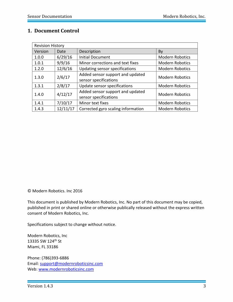
1. Document Control
Revision History
Version Date Description By
1.0.0 6/29/16 Initial Document Modern Robotics
1.0.1 9/9/16 Minor corrections and text fixes Modern Robotics
1.2.0 12/6/16 Updating sensor specifications Modern Robotics
1.3.0 2/6/17 Added sensor support and updated sensor specifications
Modern Robotics
1.3.1 2/8/17 Update sensor specifications Modern Robotics
1.4.0 4/12/17 Added sensor support and updated sensor specifications
Modern Robotics
1.4.1 7/10/17 Minor text fixes Modern Robotics
1.4.3 12/11/17 Corrected gyro scaling information Modern Robotics
© Modern Robotics. Inc 2016 This document is published by Modern Robotics, Inc. No part of this document may be copied, published in print or shared online or otherwise publically released without the express written consent of Modern Robotics, Inc. Specifications subject to change without notice. Modern Robotics, Inc 13335 SW 124th St Miami, FL 33186 Phone: (786)393-6886 Email: [email protected] Web: www.modernroboticsinc.com
Sensor Documentation Modern Robotics, Inc.
Version 1.4.3 4
2. Introduction
The following document is a guide for the use and implementation of all Modern Robotics Sensors. Modern Robotics Sensors are built in a robust plastic housing with either a three or four wire connector for easy connection to various Modern Robotics Controllers. These sensors are designed for work, play and education with a housing tailored to fit the Matrix Robotics System’s 8mm grid. For more information on Modern Robotics products and services, go to http://modernroboticsinc.com/. For guided lesson plans and video tutorials on Modern Robotics products, please visit http://modernroboticsedu.com/.
Sensor Documentation Modern Robotics, Inc.
Version 1.4.3 5
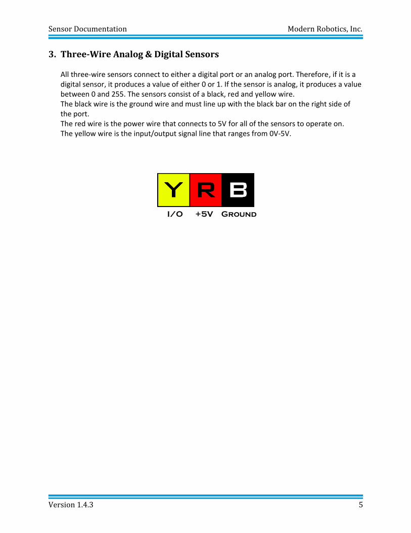
3. Three-Wire Analog & Digital Sensors All three-wire sensors connect to either a digital port or an analog port. Therefore, if it is a digital sensor, it produces a value of either 0 or 1. If the sensor is analog, it produces a value between 0 and 255. The sensors consist of a black, red and yellow wire. The black wire is the ground wire and must line up with the black bar on the right side of the port. The red wire is the power wire that connects to 5V for all of the sensors to operate on. The yellow wire is the input/output signal line that ranges from 0V-5V.
I/O +5V Ground
Sensor Documentation Modern Robotics, Inc.
Version 1.4.3 6
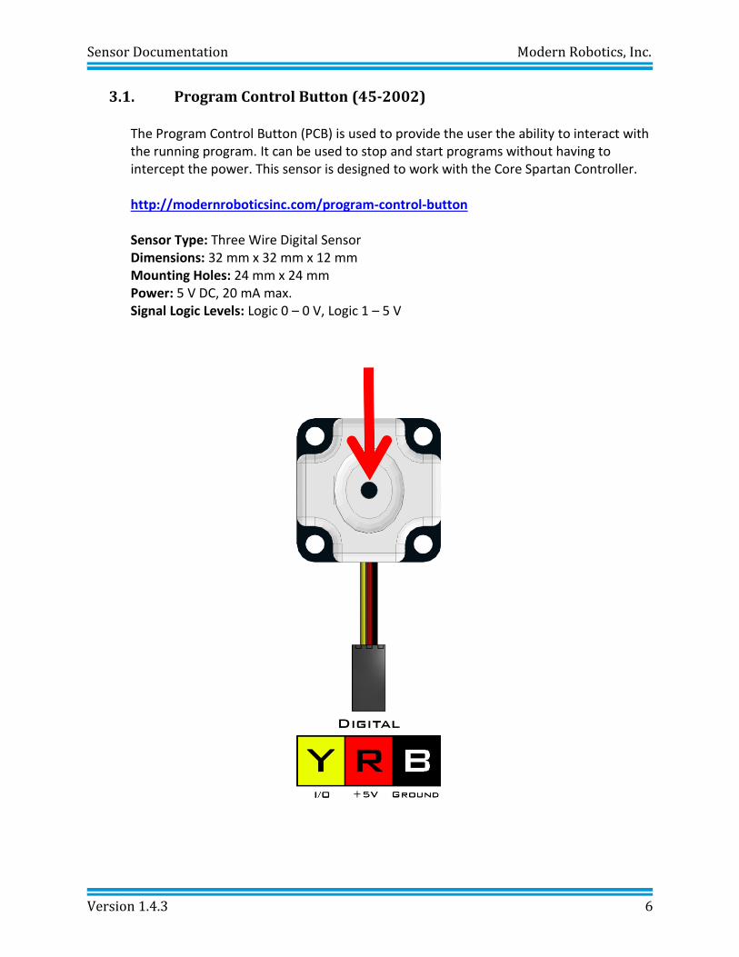
3.1. Program Control Button (45-2002)
The Program Control Button (PCB) is used to provide the user the ability to interact with the running program. It can be used to stop and start programs without having to intercept the power. This sensor is designed to work with the Core Spartan Controller.
http://modernroboticsinc.com/program-control-button
Sensor Type: Three Wire Digital Sensor Dimensions: 32 mm x 32 mm x 12 mm Mounting Holes: 24 mm x 24 mm
Power: 5 V DC, 20 mA max. Signal Logic Levels: Logic 0 – 0 V, Logic 1 – 5 V
Sensor Documentation Modern Robotics, Inc.
Version 1.4.3 7
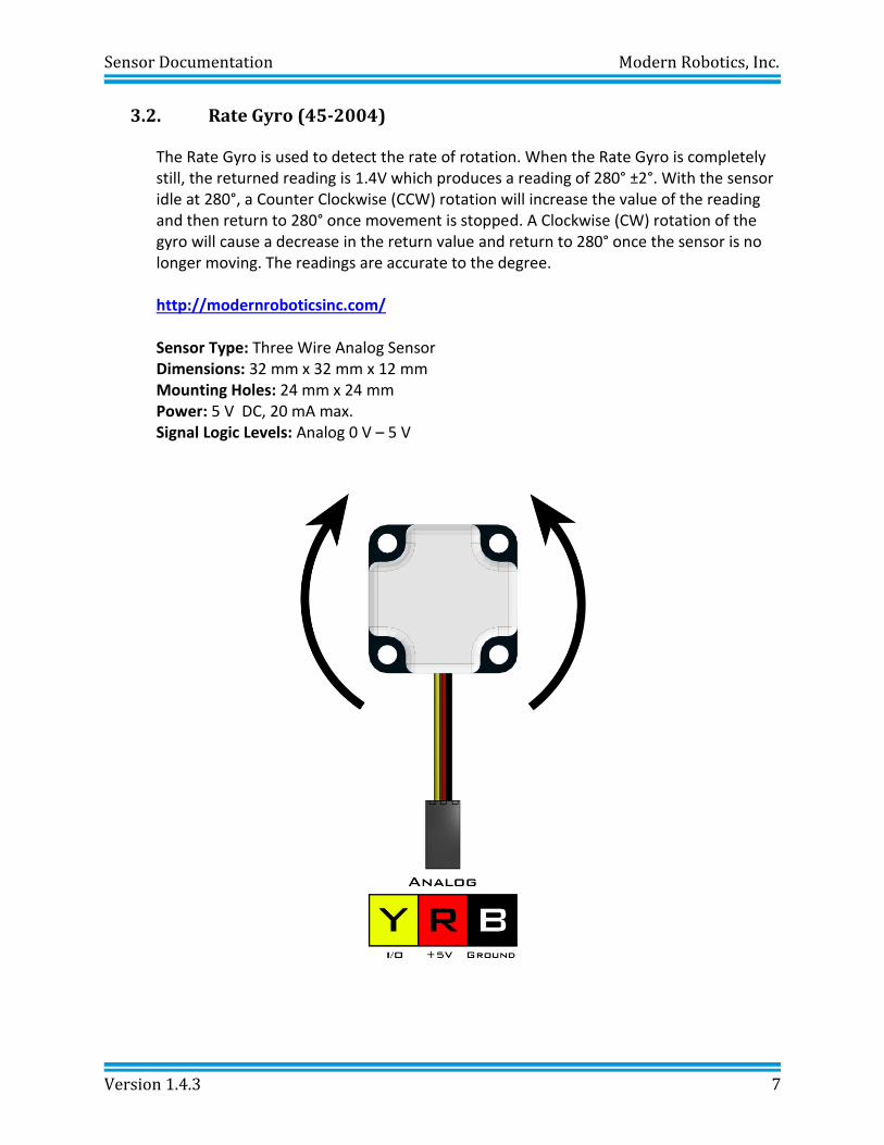
3.2. Rate Gyro (45-2004)
The Rate Gyro is used to detect the rate of rotation. When the Rate Gyro is completely still, the returned reading is 1.4V which produces a reading of 280° ±2°. With the sensor idle at 280°, a Counter Clockwise (CCW) rotation will increase the value of the reading and then return to 280° once movement is stopped. A Clockwise (CW) rotation of the gyro will cause a decrease in the return value and return to 280° once the sensor is no longer moving. The readings are accurate to the degree. http://modernroboticsinc.com/
Sensor Type: Three Wire Analog Sensor Dimensions: 32 mm x 32 mm x 12 mm Mounting Holes: 24 mm x 24 mm
Power: 5 V DC, 20 mA max. Signal Logic Levels: Analog 0 V – 5 V
Sensor Documentation Modern Robotics, Inc.
Version 1.4.3 8
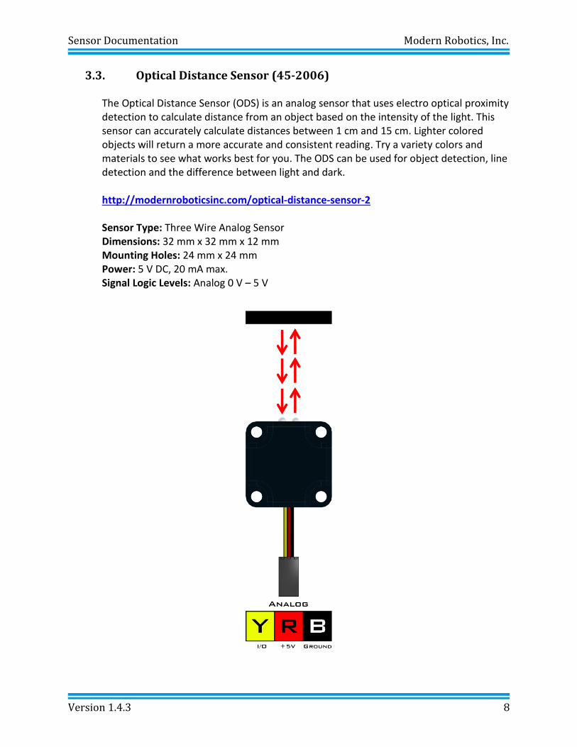
3.3. Optical Distance Sensor (45-2006) The Optical Distance Sensor (ODS) is an analog sensor that uses electro optical proximity detection to calculate distance from an object based on the intensity of the light. This sensor can accurately calculate distances between 1 cm and 15 cm. Lighter colored objects will return a more accurate and consistent reading. Try a variety colors and materials to see what works best for you. The ODS can be used for object detection, line detection and the difference between light and dark. http://modernroboticsinc.com/optical-distance-sensor-2
Sensor Type: Three Wire Analog Sensor Dimensions: 32 mm x 32 mm x 12 mm Mounting Holes: 24 mm x 24 mm
Power: 5 V DC, 20 mA max. Signal Logic Levels: Analog 0 V – 5 V
Sensor Documentation Modern Robotics, Inc.
Version 1.4.3 9
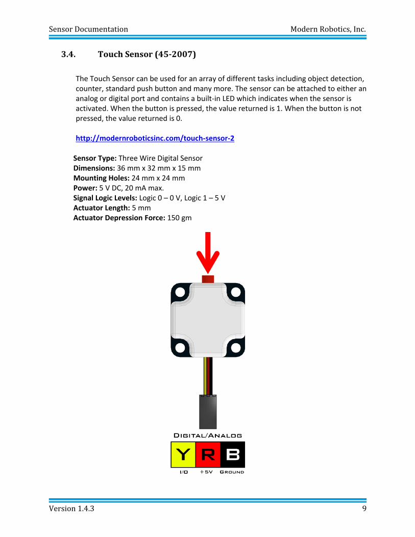
3.4. Touch Sensor (45-2007)
The Touch Sensor can be used for an array of different tasks including object detection, counter, standard push button and many more. The sensor can be attached to either an analog or digital port and contains a built-in LED which indicates when the sensor is activated. When the button is pressed, the value returned is 1. When the button is not pressed, the value returned is 0. http://modernroboticsinc.com/touch-sensor-2
Sensor Type: Three Wire Digital Sensor Dimensions: 36 mm x 32 mm x 15 mm Mounting Holes: 24 mm x 24 mm
Power: 5 V DC, 20 mA max. Signal Logic Levels: Logic 0 – 0 V, Logic 1 – 5 V Actuator Length: 5 mm Actuator Depression Force: 150 gm
Sensor Documentation Modern Robotics, Inc.
Version 1.4.3 10
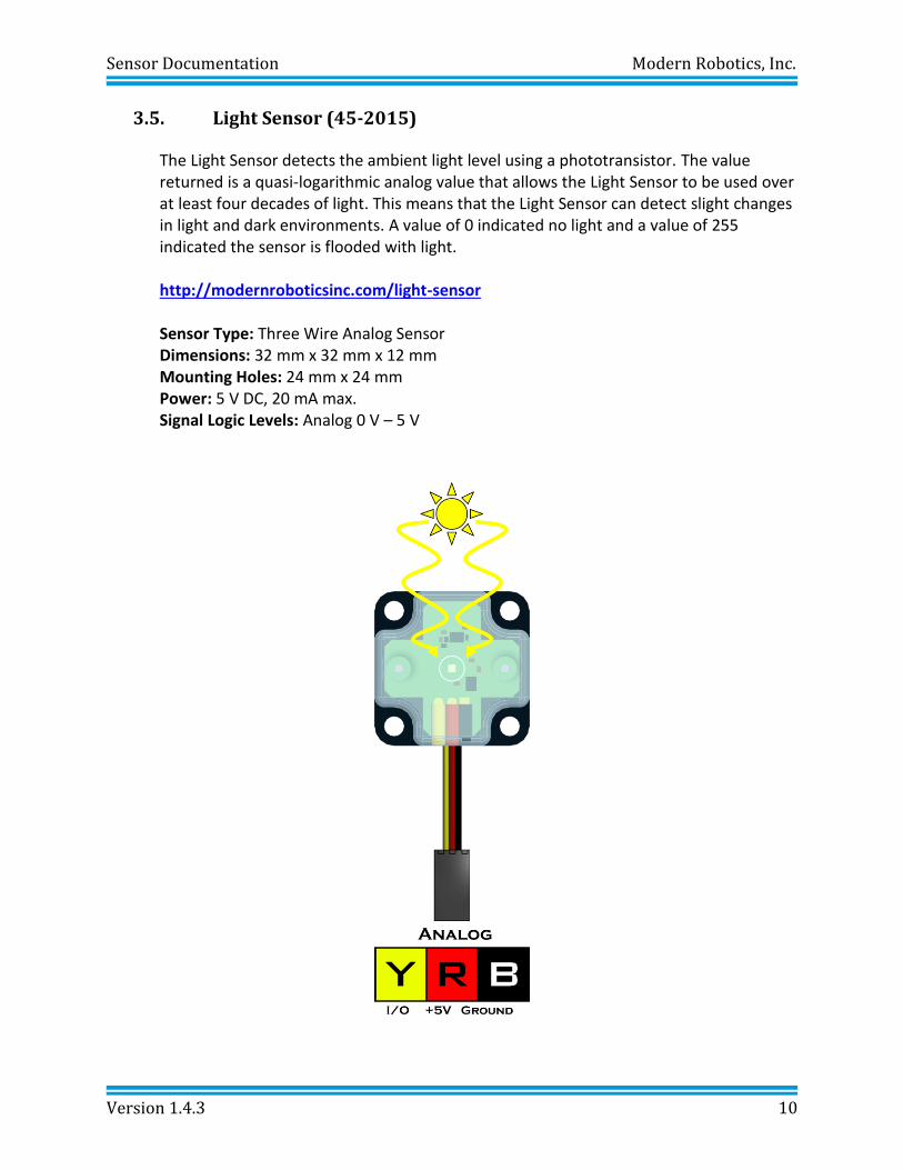
3.5. Light Sensor (45-2015)
The Light Sensor detects the ambient light level using a phototransistor. The value returned is a quasi-logarithmic analog value that allows the Light Sensor to be used over at least four decades of light. This means that the Light Sensor can detect slight changes in light and dark environments. A value of 0 indicated no light and a value of 255 indicated the sensor is flooded with light. http://modernroboticsinc.com/light-sensor
Sensor Type: Three Wire Analog Sensor Dimensions: 32 mm x 32 mm x 12 mm Mounting Holes: 24 mm x 24 mm
Power: 5 V DC, 20 mA max. Signal Logic Levels: Analog 0 V – 5 V
Sensor Documentation Modern Robotics, Inc.
Version 1.4.3 11
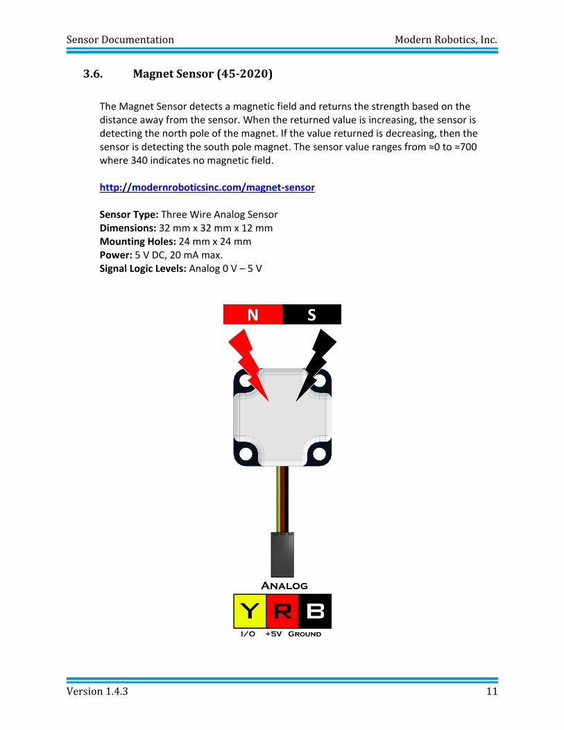
3.6. Magnet Sensor (45-2020)
The Magnet Sensor detects a magnetic field and returns the strength based on the distance away from the sensor. When the returned value is increasing, the sensor is detecting the north pole of the magnet. If the value returned is decreasing, then the sensor is detecting the south pole magnet. The sensor value ranges from ≈0 to ≈700 where 340 indicates no magnetic field. http://modernroboticsinc.com/magnet-sensor
Sensor Type: Three Wire Analog Sensor Dimensions: 32 mm x 32 mm x 12 mm Mounting Holes: 24 mm x 24 mm
Power: 5 V DC, 20 mA max. Signal Logic Levels: Analog 0 V – 5 V
Sensor Documentation Modern Robotics, Inc.
Version 1.4.3 12
+5V SDA SCL Ground
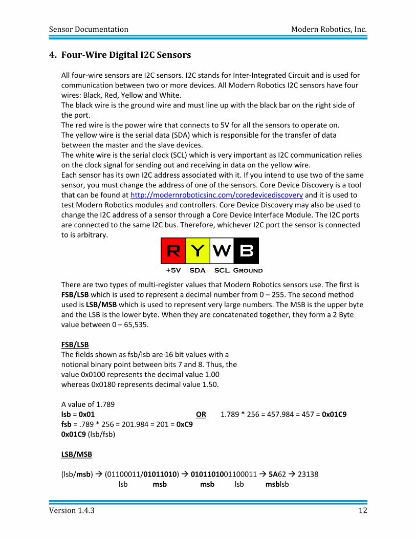
4. Four-Wire Digital I2C Sensors
All four-wire sensors are I2C sensors. I2C stands for Inter-Integrated Circuit and is used for communication between two or more devices. All Modern Robotics I2C sensors have four wires: Black, Red, Yellow and White. The black wire is the ground wire and must line up with the black bar on the right side of the port. The red wire is the power wire that connects to 5V for all the sensors to operate on. The yellow wire is the serial data (SDA) which is responsible for the transfer of data between the master and the slave devices. The white wire is the serial clock (SCL) which is very important as I2C communication relies on the clock signal for sending out and receiving in data on the yellow wire. Each sensor has its own I2C address associated with it. If you intend to use two of the same sensor, you must change the address of one of the sensors. Core Device Discovery is a tool that can be found at http://modernroboticsinc.com/coredevicediscovery and it is used to test Modern Robotics modules and controllers. Core Device Discovery may also be used to change the I2C address of a sensor through a Core Device Interface Module. The I2C ports are connected to the same I2C bus. Therefore, whichever I2C port the sensor is connected to is arbitrary.
There are two types of multi-register values that Modern Robotics sensors use. The first is FSB/LSB which is used to represent a decimal number from 0 – 255. The second method used is LSB/MSB which is used to represent very large numbers. The MSB is the upper byte and the LSB is the lower byte. When they are concatenated together, they form a 2 Byte value between 0 – 65,535. FSB/LSB The fields shown as fsb/lsb are 16 bit values with a notional binary point between bits 7 and 8. Thus, the value 0x0100 represents the decimal value 1.00 whereas 0x0180 represents decimal value 1.50. A value of 1.789 lsb = 0x01 OR 1.789 * 256 = 457.984 = 457 = 0x01C9 fsb = .789 * 256 = 201.984 = 201 = 0xC9 0x01C9 (lsb/fsb)
LSB/MSB (lsb/msb) (01100011/01011010) 0101101001100011 5A62 23138
lsb msb msb lsb msblsb
Sensor Documentation Modern Robotics, Inc.
Version 1.4.3 13
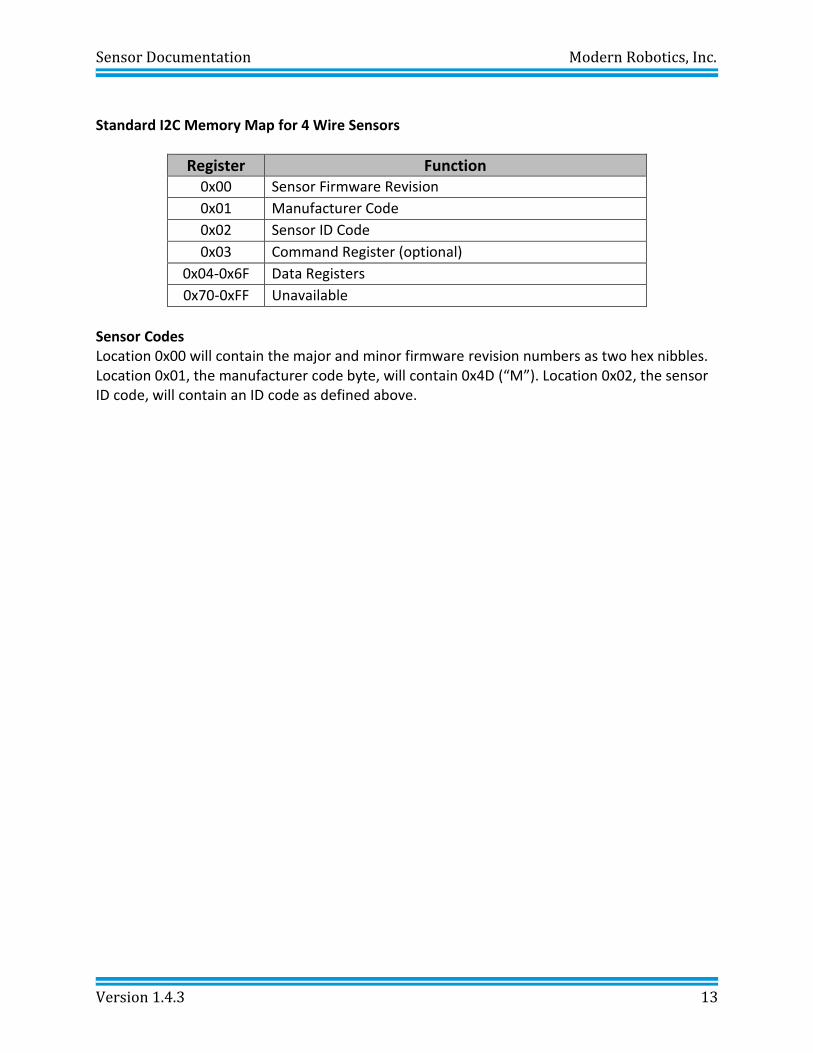
Standard I2C Memory Map for 4 Wire Sensors
Register Function 0x00 Sensor Firmware Revision
0x01 Manufacturer Code
0x02 Sensor ID Code
0x03 Command Register (optional)
0x04-0x6F Data Registers
0x70-0xFF Unavailable
Sensor Codes Location 0x00 will contain the major and minor firmware revision numbers as two hex nibbles. Location 0x01, the manufacturer code byte, will contain 0x4D (“M”). Location 0x02, the sensor ID code, will contain an ID code as defined above.
Sensor Documentation Modern Robotics, Inc.
Version 1.4.3 14
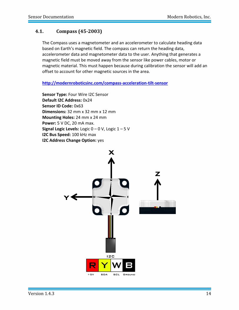
4.1. Compass (45-2003)
The Compass uses a magnetometer and an accelerometer to calculate heading data based on Earth’s magnetic field. The compass can return the heading data, accelerometer data and magnetometer data to the user. Anything that generates a magnetic field must be moved away from the sensor like power cables, motor or magnetic material. This must happen because during calibration the sensor will add an offset to account for other magnetic sources in the area. http://modernroboticsinc.com/compass-acceleration-tilt-sensor Sensor Type: Four Wire I2C Sensor Default I2C Address: 0x24 Sensor ID Code: 0x63 Dimensions: 32 mm x 32 mm x 12 mm Mounting Holes: 24 mm x 24 mm
Power: 5 V DC, 20 mA max. Signal Logic Levels: Logic 0 – 0 V, Logic 1 – 5 V
I2C Bus Speed: 100 kHz max I2C Address Change Option: yes
Sensor Documentation Modern Robotics, Inc.
Version 1.4.3 15
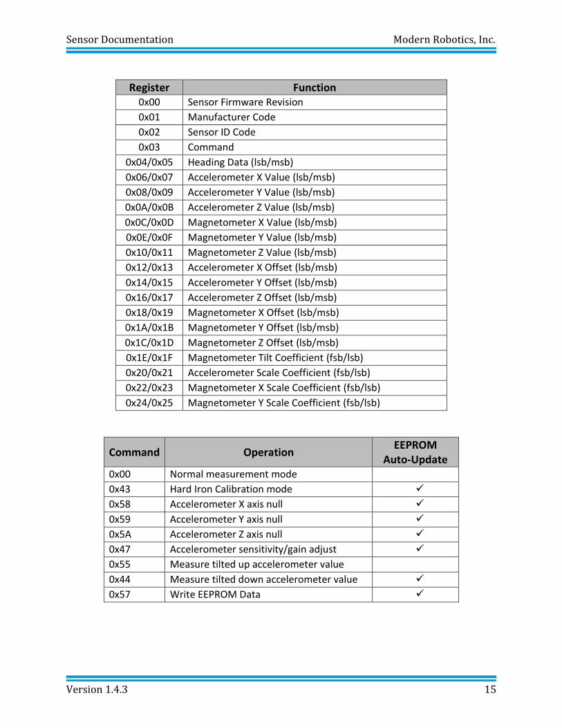
Register Function 0x00 Sensor Firmware Revision
0x01 Manufacturer Code
0x02 Sensor ID Code
0x03 Command
0x04/0x05 Heading Data (lsb/msb)
0x06/0x07 Accelerometer X Value (lsb/msb)
0x08/0x09 Accelerometer Y Value (lsb/msb)
0x0A/0x0B Accelerometer Z Value (lsb/msb)
0x0C/0x0D Magnetometer X Value (lsb/msb)
0x0E/0x0F Magnetometer Y Value (lsb/msb)
0x10/0x11 Magnetometer Z Value (lsb/msb)
0x12/0x13 Accelerometer X Offset (lsb/msb)
0x14/0x15 Accelerometer Y Offset (lsb/msb)
0x16/0x17 Accelerometer Z Offset (lsb/msb)
0x18/0x19 Magnetometer X Offset (lsb/msb)
0x1A/0x1B Magnetometer Y Offset (lsb/msb)
0x1C/0x1D Magnetometer Z Offset (lsb/msb)
0x1E/0x1F Magnetometer Tilt Coefficient (fsb/lsb)
0x20/0x21 Accelerometer Scale Coefficient (fsb/lsb)
0x22/0x23 Magnetometer X Scale Coefficient (fsb/lsb)
0x24/0x25 Magnetometer Y Scale Coefficient (fsb/lsb)
Command Operation EEPROM
Auto-Update 0x00 Normal measurement mode
0x43 Hard Iron Calibration mode ✓
0x58 Accelerometer X axis null ✓
0x59 Accelerometer Y axis null ✓
0x5A Accelerometer Z axis null ✓
0x47 Accelerometer sensitivity/gain adjust ✓
0x55 Measure tilted up accelerometer value
0x44 Measure tilted down accelerometer value ✓
0x57 Write EEPROM Data ✓
Sensor Documentation Modern Robotics, Inc.
Version 1.4.3 16
During normal operation, the LED will blink briefly at 1Hz. During Hard Iron Calibration, the LED will blink at ½Hz. During tilt up and tilt down calibration the LED will be on during a period of calibration measurement. Hard Iron Calibration: Hard Iron Calibration is entered by setting the command location to 0x43. Once Hard Iron Calibration is active rotate the Compass 360°, making sure it does not tilt, for a period of 5 seconds. Once the rotation procedure is complete, the command location must be set to 0x00 to signal that calibration is complete. If the data collected during the rotation was good, the Compass will enter Normal Measurement Mode using the new calibration data. If the data collected during the rotation was not good, the command value will change to 0x46 and the Compass will enter Normal Measurement Mode using the previous calibration data. Tilt Compensation: Tilt compensation is performed in two steps, tilt up and tilt down in that order. The first step is tilt up. To set the Compass up for tilt up measurement, the Compass should be pointed due North and set with the front of the device tiled up by approximately 20°. Then the command location should be set to 0x55 while the Compass is held perfectly still. Once the LED extinguishes itself, the command location will return to 0x00, indicating that tilt up data has been captured. The second step is tilt down. To set the Compass up for tilt down measurement, the Compass should be pointed due North and set with the front of the device tilted down by approximately 20°. Then the command location should be set to 0x44 while the compass is held perfectly still. Once the LED extinguishes itself, the command location will return 0x00, indicating that tilt down data has been captured and the tilt compensation coefficient has been acquired. If the two tilt steps are not performed in the correct order, or some other error is detected, the command location will be set to 0x46 and the Compass will enter Normal Measurement Mode using the previous tilt compensation coefficient.
Accelerometer Nulling:
Accelerometer axis nulling is performed using the three axis null commands. For both the x and y axis nulling should be performed with the device set perfectly level. Setting the command location to 0x58 will update the accelerometer X axis offset. Setting the command location to 0x59 will update the accelerometer Y axis offset. For the Z axis nulling, the device should be set to be perfectly vertical. Setting the command location to 0x5A will update the accelerometer Z axis offset
Sensor Documentation Modern Robotics, Inc.
Version 1.4.3 17
Accelerometer Scale Coefficient: The Accelerometer Scale Coefficient is adjusted to be approximately 1mg/count. If greater measurement accuracy is required, the Accelerometer Scale Coefficient (fsb/lsb) may be set by the user. This can be simply done by setting the device perfectly vertical and obtaining the accelerometer X value via registers 0x06 and 0x07. If the value read were to be 850, then the Once the Accelerometer Scale Coefficient has been adjusted, the 0x57 command should be issued to ensure the new value is recorded in EEPROM. Example: Step 1: Sensor Position Set the sensor vertical so that the wires are pointing up in the air. Step 2: Find the X Value Find the Accelerometer X Value - Register 0x06 (lsb)/0x07 (msb)
Register 0x06 (lsb) = 0xE2 Register 0x07 (msb) = 0x04 X Value = msb:lsb = 0x04:0xE2 = 0x04E2 = 1250 Step 3: Calculate Scaling Value Scaling Value = 1000/X Value = 1000/1250 = .8 Step 4: Calculate Register Values Register Value (lsb:fsb) = .8 * 256 = 204.8 = 204 = 0xCC = 0x00CC Step 5: Enter Values into Accelerometer Scale Coefficient Register Accelerometer Scale Coefficient = 0x20 (fsb)/0x21 (lsb) Register 0x20 (fsb) = 0xCC Register 0x21 (lsb) = 0x00 Step 6: Saving the value to EEPROM
Enter a value of 0x57 (Write EEPROM Data) to the Command Register (0x03) to save the scaled value into EEPROM.
Sensor Documentation Modern Robotics, Inc.
Version 1.4.3 18
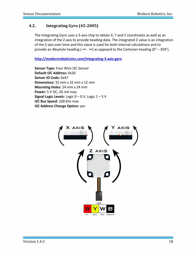
4.2. Integrating Gyro (45-2005)
The Integrating Gyro uses a 3-axis chip to obtain X, Y and Z coordinates as well as an integration of the Z-axis to provide heading data. The integrated Z value is an integration of the Z-axis over time and this value is used for both internal calculations and to provide an Absolute heading (-∞ - ∞) as opposed to the Cartesian heading (0° – 359°). http://modernroboticsinc.com/integrating-3-axis-gyro Sensor Type: Four Wire I2C Sensor Default I2C Address: 0x20 Sensor ID Code: 0x47 Dimensions: 32 mm x 32 mm x 12 mm Mounting Holes: 24 mm x 24 mm
Power: 5 V DC, 20 mA max. Signal Logic Levels: Logic 0 – 0 V, Logic 1 – 5 V
I2C Bus Speed: 100 kHz max I2C Address Change Option: yes
Sensor Documentation Modern Robotics, Inc.
Version 1.4.3 19
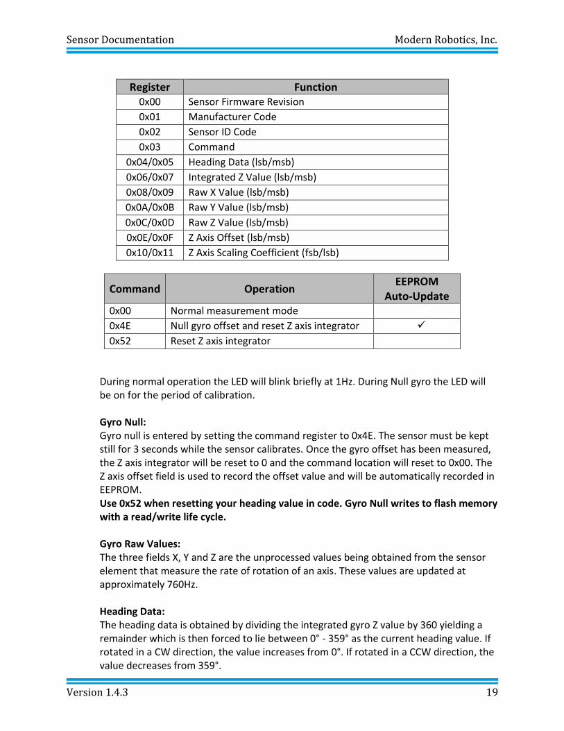
Register Function 0x00 Sensor Firmware Revision
0x01 Manufacturer Code
0x02 Sensor ID Code
0x03 Command
0x04/0x05 Heading Data (lsb/msb)
0x06/0x07 Integrated Z Value (lsb/msb)
0x08/0x09 Raw X Value (lsb/msb)
0x0A/0x0B Raw Y Value (lsb/msb)
0x0C/0x0D Raw Z Value (lsb/msb)
0x0E/0x0F Z Axis Offset (lsb/msb)
0x10/0x11 Z Axis Scaling Coefficient (fsb/lsb)
Command Operation EEPROM
Auto-Update 0x00 Normal measurement mode
0x4E Null gyro offset and reset Z axis integrator ✓
0x52 Reset Z axis integrator
During normal operation the LED will blink briefly at 1Hz. During Null gyro the LED will be on for the period of calibration. Gyro Null: Gyro null is entered by setting the command register to 0x4E. The sensor must be kept still for 3 seconds while the sensor calibrates. Once the gyro offset has been measured, the Z axis integrator will be reset to 0 and the command location will reset to 0x00. The Z axis offset field is used to record the offset value and will be automatically recorded in EEPROM. Use 0x52 when resetting your heading value in code. Gyro Null writes to flash memory with a read/write life cycle.
Gyro Raw Values: The three fields X, Y and Z are the unprocessed values being obtained from the sensor element that measure the rate of rotation of an axis. These values are updated at approximately 760Hz. Heading Data: The heading data is obtained by dividing the integrated gyro Z value by 360 yielding a remainder which is then forced to lie between 0° - 359° as the current heading value. If rotated in a CW direction, the value increases from 0°. If rotated in a CCW direction, the value decreases from 359°.
Sensor Documentation Modern Robotics, Inc.
Version 1.4.3 20
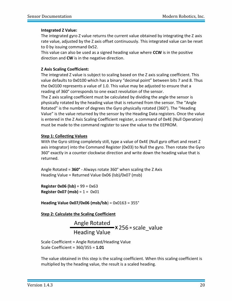
Integrated Z Value: The integrated gyro Z value returns the current value obtained by integrating the Z axis rate value, adjusted by the Z axis offset continuously. This integrated value can be reset to 0 by issuing command 0x52. This value can also be used as a signed heading value where CCW is in the positive direction and CW is in the negative direction. Z Axis Scaling Coefficient: The integrated Z value is subject to scaling based on the Z axis scaling coefficient. This value defaults to 0x0100 which has a binary “decimal point” between bits 7 and 8. Thus the 0x0100 represents a value of 1.0. This value may be adjusted to ensure that a reading of 360° corresponds to one exact revolution of the sensor. The Z axis scaling coefficient must be calculated by dividing the angle the sensor is physically rotated by the heading value that is returned from the sensor. The “Angle Rotated” is the number of degrees the Gyro physically rotated (360°). The “Heading Value” is the value returned by the sensor by the Heading Data registers. Once the value is entered in the Z Axis Scaling Coefficient register, a command of 0x4E (Null Operation) must be made to the command register to save the value to the EEPROM. Step 1: Collecting Values With the Gyro sitting completely still, type a value of 0x4E (Null gyro offset and reset Z axis integrator) into the Command Register (0x03) to Null the gyro. Then rotate the Gyro 360° exactly in a counter clockwise direction and write down the heading value that is returned. Angle Rotated = 360° - Always rotate 360° when scaling the Z Axis Heading Value = Returned Value 0x06 (lsb)/0x07 (msb) Register 0x06 (lsb) = 99 = 0x63 Register 0x07 (msb) = 1 = 0x01 Heading Value 0x07/0x06 (msb/lsb) = 0x0163 = 355° Step 2: Calculate the Scaling Coefficient
Scale Coefficient = Angle Rotated/Heading Value Scale Coefficient = 360/355 = 1.01
The value obtained in this step is the scaling coefficient. When this scaling coefficient is multiplied by the heading value, the result is a scaled heading.
Sensor Documentation Modern Robotics, Inc.
Version 1.4.3 21
Step 3: Calculate Register Values Register Value (lsb:fsb) = 1.01 * 256 = 258.56
Round Down: 258 = 0x0102
Step 4: Enter Values into Z Axis Scaling Coefficient Register Z Axis Scaling Coefficient = 0x10 (fsb)/0x11 (lsb) Register 0x10 (fsb) = 0x02 Register 0x11 (lsb) = 0x01
Click “WRITE” to enter the values into the registers. You can then “READ” back to verify the registers contain the correct value.
Step 5: Saving the value to EEPROM
Enter a value of 0x4E (Null gyro offset and reset Z axis integrator) to the Command Register (0x03) to save the scaled value into EEPROM and recalibrate the Gyro with the new scaling factor.
Sensor Documentation Modern Robotics, Inc.
Version 1.4.3 22
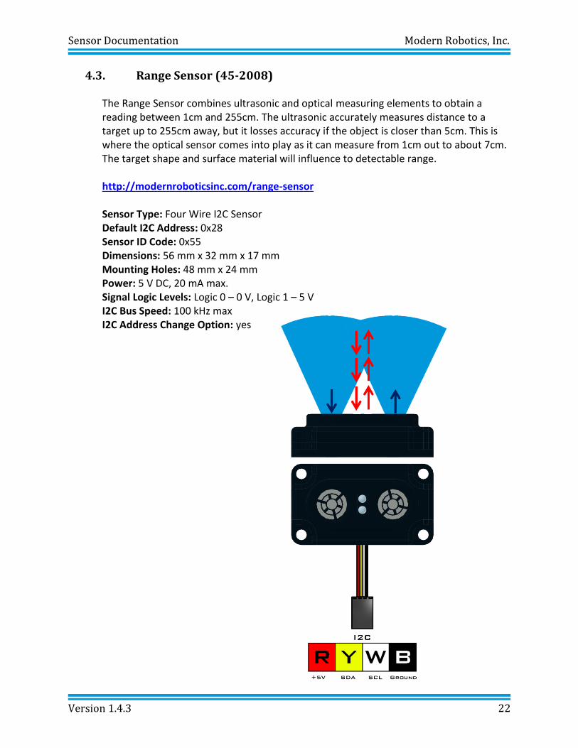
4.3. Range Sensor (45-2008)
The Range Sensor combines ultrasonic and optical measuring elements to obtain a reading between 1cm and 255cm. The ultrasonic accurately measures distance to a target up to 255cm away, but it losses accuracy if the object is closer than 5cm. This is where the optical sensor comes into play as it can measure from 1cm out to about 7cm. The target shape and surface material will influence to detectable range. http://modernroboticsinc.com/range-sensor Sensor Type: Four Wire I2C Sensor Default I2C Address: 0x28 Sensor ID Code: 0x55 Dimensions: 56 mm x 32 mm x 17 mm Mounting Holes: 48 mm x 24 mm
Power: 5 V DC, 20 mA max. Signal Logic Levels: Logic 0 – 0 V, Logic 1 – 5 V
I2C Bus Speed: 100 kHz max I2C Address Change Option: yes
Sensor Documentation Modern Robotics, Inc.
Version 1.4.3 23
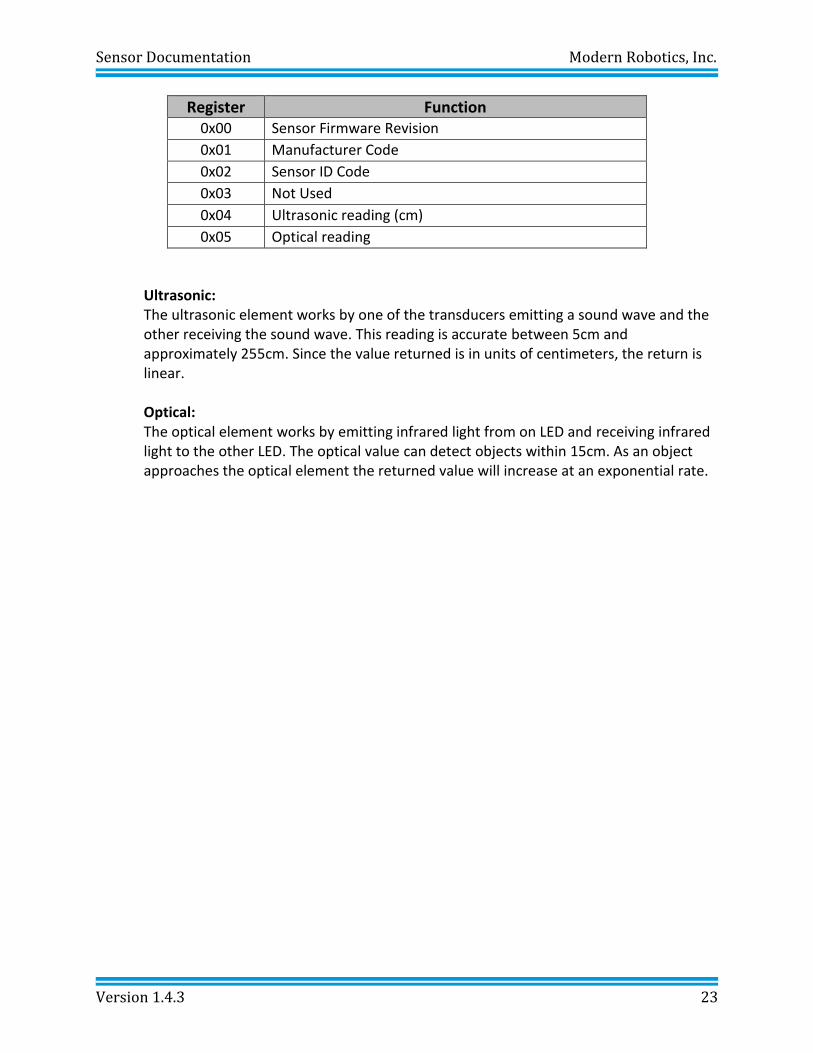
Register Function 0x00 Sensor Firmware Revision
0x01 Manufacturer Code
0x02 Sensor ID Code
0x03 Not Used
0x04 Ultrasonic reading (cm)
0x05 Optical reading
Ultrasonic: The ultrasonic element works by one of the transducers emitting a sound wave and the other receiving the sound wave. This reading is accurate between 5cm and approximately 255cm. Since the value returned is in units of centimeters, the return is linear. Optical: The optical element works by emitting infrared light from on LED and receiving infrared light to the other LED. The optical value can detect objects within 15cm. As an object approaches the optical element the returned value will increase at an exponential rate.
Sensor Documentation Modern Robotics, Inc.
Version 1.4.3 24
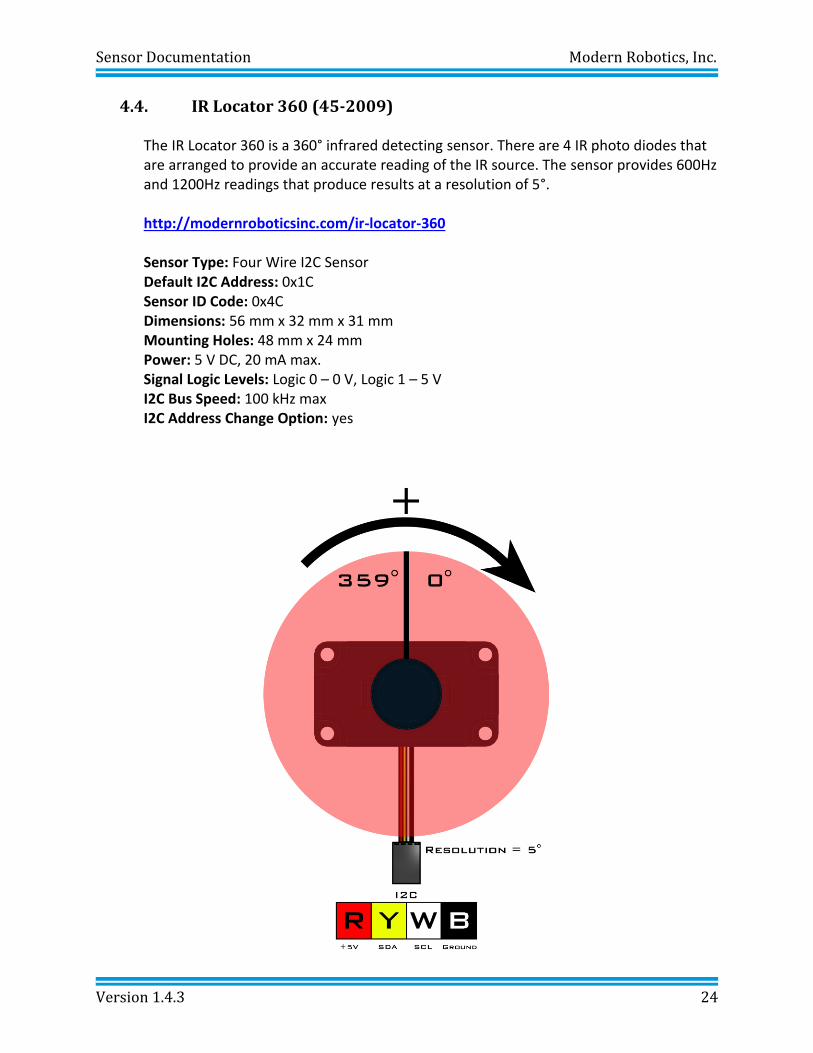
4.4. IR Locator 360 (45-2009)
The IR Locator 360 is a 360° infrared detecting sensor. There are 4 IR photo diodes that are arranged to provide an accurate reading of the IR source. The sensor provides 600Hz and 1200Hz readings that produce results at a resolution of 5°. http://modernroboticsinc.com/ir-locator-360 Sensor Type: Four Wire I2C Sensor Default I2C Address: 0x1C Sensor ID Code: 0x4C Dimensions: 56 mm x 32 mm x 31 mm Mounting Holes: 48 mm x 24 mm
Power: 5 V DC, 20 mA max. Signal Logic Levels: Logic 0 – 0 V, Logic 1 – 5 V
I2C Bus Speed: 100 kHz max I2C Address Change Option: yes
Sensor Documentation Modern Robotics, Inc.
Version 1.4.3 25
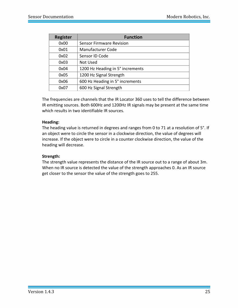
The frequencies are channels that the IR Locator 360 uses to tell the difference between IR emitting sources. Both 600Hz and 1200Hz IR signals may be present at the same time which results in two identifiable IR sources.
Heading: The heading value is returned in degrees and ranges from 0 to 71 at a resolution of 5°. If an object were to circle the sensor in a clockwise direction, the value of degrees will increase. If the object were to circle in a counter clockwise direction, the value of the heading will decrease. Strength: The strength value represents the distance of the IR source out to a range of about 3m. When no IR source is detected the value of the strength approaches 0. As an IR source get closer to the sensor the value of the strength goes to 255.
Register Function 0x00 Sensor Firmware Revision
0x01 Manufacturer Code
0x02 Sensor ID Code
0x03 Not Used
0x04 1200 Hz Heading in 5° increments
0x05 1200 Hz Signal Strength
0x06 600 Hz Heading in 5° increments
0x07 600 Hz Signal Strength
Sensor Documentation Modern Robotics, Inc.
Version 1.4.3 26
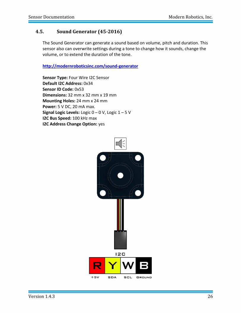
4.5. Sound Generator (45-2016)
The Sound Generator can generate a sound based on volume, pitch and duration. This sensor also can overwrite settings during a tone to change how it sounds, change the volume, or to extend the duration of the tone. http://modernroboticsinc.com/sound-generator Sensor Type: Four Wire I2C Sensor Default I2C Address: 0x34
Sensor ID Code: 0x53 Dimensions: 32 mm x 32 mm x 19 mm Mounting Holes: 24 mm x 24 mm
Power: 5 V DC, 20 mA max. Signal Logic Levels: Logic 0 – 0 V, Logic 1 – 5 V
I2C Bus Speed: 100 kHz max I2C Address Change Option: yes
Sensor Documentation Modern Robotics, Inc.
Version 1.4.3 27
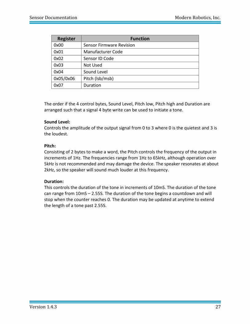
Register Function 0x00 Sensor Firmware Revision
0x01 Manufacturer Code
0x02 Sensor ID Code
0x03 Not Used
0x04 Sound Level
0x05/0x06 Pitch (lsb/msb)
0x07 Duration
The order if the 4 control bytes, Sound Level, Pitch low, Pitch high and Duration are arranged such that a signal 4 byte write can be used to initiate a tone.
Sound Level: Controls the amplitude of the output signal from 0 to 3 where 0 is the quietest and 3 is the loudest. Pitch: Consisting of 2 bytes to make a word, the Pitch controls the frequency of the output in increments of 1Hz. The frequencies range from 1Hz to 65kHz, although operation over 5kHz is not recommended and may damage the device. The speaker resonates at about 2kHz, so the speaker will sound much louder at this frequency.
Duration: This controls the duration of the tone in increments of 10mS. The duration of the tone can range from 10mS – 2.55S. The duration of the tone begins a countdown and will stop when the counter reaches 0. The duration may be updated at anytime to extend the length of a tone past 2.55S.
Sensor Documentation Modern Robotics, Inc.
Version 1.4.3 28
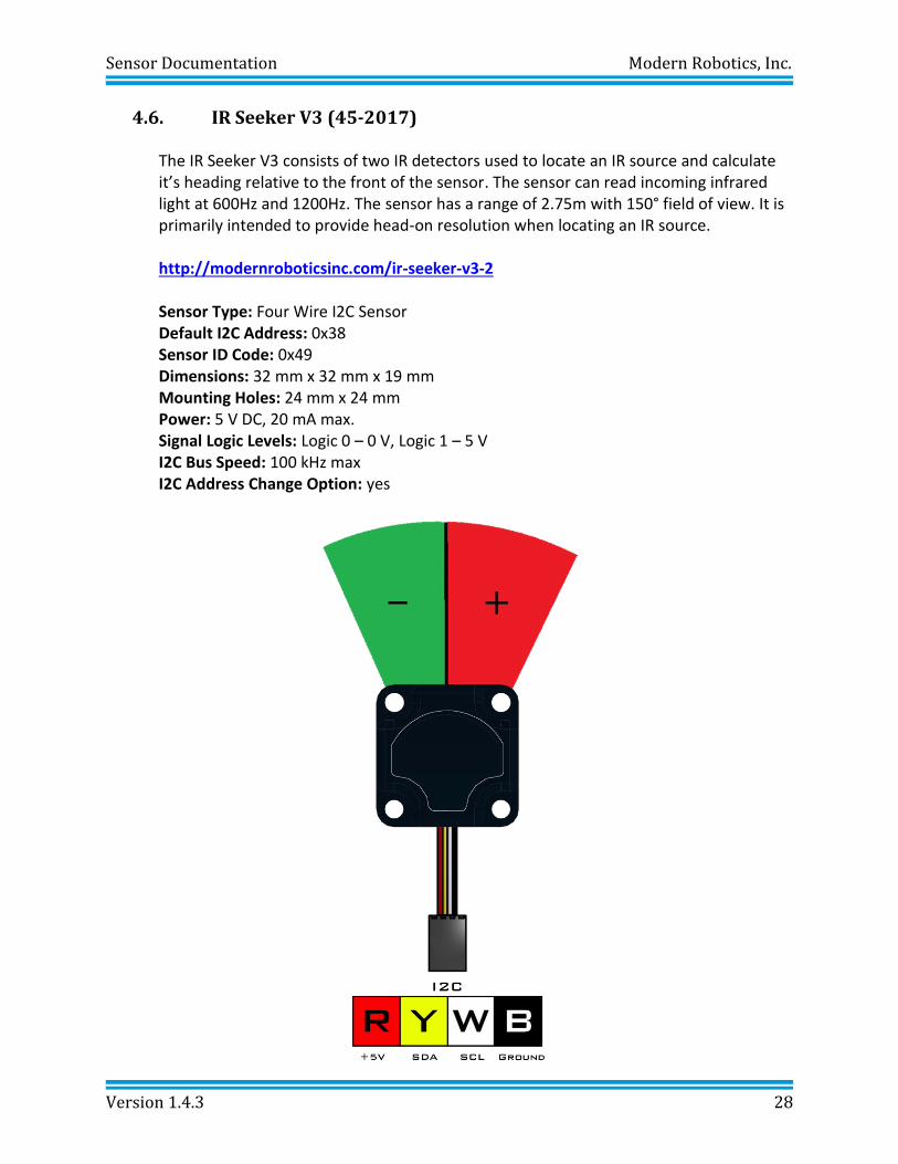
4.6. IR Seeker V3 (45-2017)
The IR Seeker V3 consists of two IR detectors used to locate an IR source and calculate it’s heading relative to the front of the sensor. The sensor can read incoming infrared light at 600Hz and 1200Hz. The sensor has a range of 2.75m with 150° field of view. It is primarily intended to provide head-on resolution when locating an IR source. http://modernroboticsinc.com/ir-seeker-v3-2 Sensor Type: Four Wire I2C Sensor Default I2C Address: 0x38 Sensor ID Code: 0x49 Dimensions: 32 mm x 32 mm x 19 mm Mounting Holes: 24 mm x 24 mm
Power: 5 V DC, 20 mA max. Signal Logic Levels: Logic 0 – 0 V, Logic 1 – 5 V
I2C Bus Speed: 100 kHz max I2C Address Change Option: yes
Sensor Documentation Modern Robotics, Inc.
Version 1.4.3 29
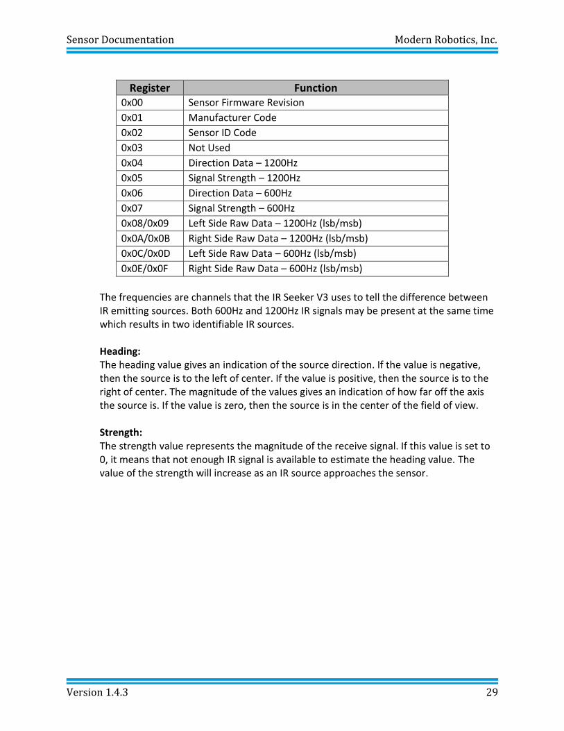
Register Function 0x00 Sensor Firmware Revision
0x01 Manufacturer Code
0x02 Sensor ID Code
0x03 Not Used
0x04 Direction Data – 1200Hz
0x05 Signal Strength – 1200Hz
0x06 Direction Data – 600Hz
0x07 Signal Strength – 600Hz
0x08/0x09 Left Side Raw Data – 1200Hz (lsb/msb)
0x0A/0x0B Right Side Raw Data – 1200Hz (lsb/msb)
0x0C/0x0D Left Side Raw Data – 600Hz (lsb/msb)
0x0E/0x0F Right Side Raw Data – 600Hz (lsb/msb)
The frequencies are channels that the IR Seeker V3 uses to tell the difference between IR emitting sources. Both 600Hz and 1200Hz IR signals may be present at the same time which results in two identifiable IR sources.
Heading: The heading value gives an indication of the source direction. If the value is negative, then the source is to the left of center. If the value is positive, then the source is to the right of center. The magnitude of the values gives an indication of how far off the axis the source is. If the value is zero, then the source is in the center of the field of view. Strength: The strength value represents the magnitude of the receive signal. If this value is set to 0, it means that not enough IR signal is available to estimate the heading value. The value of the strength will increase as an IR source approaches the sensor.
Sensor Documentation Modern Robotics, Inc.
Version 1.4.3 30
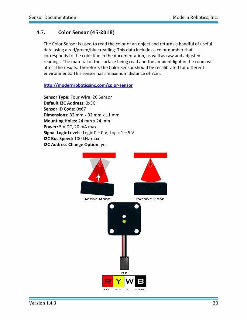
4.7. Color Sensor (45-2018)
The Color Sensor is used to read the color of an object and returns a handful of useful data using a red/green/blue reading. This data includes a color number that corresponds to the color line in the documentation, as well as raw and adjusted readings. The material of the surface being read and the ambient light in the room will affect the results. Therefore, the Color Sensor should be recalibrated for different environments. This sensor has a maximum distance of 7cm. http://modernroboticsinc.com/color-sensor Sensor Type: Four Wire I2C Sensor Default I2C Address: 0x3C Sensor ID Code: 0x67 Dimensions: 32 mm x 32 mm x 11 mm Mounting Holes: 24 mm x 24 mm
Power: 5 V DC, 20 mA max. Signal Logic Levels: Logic 0 – 0 V, Logic 1 – 5 V
I2C Bus Speed: 100 kHz max I2C Address Change Option: yes
Sensor Documentation Modern Robotics, Inc.
Version 1.4.3 31
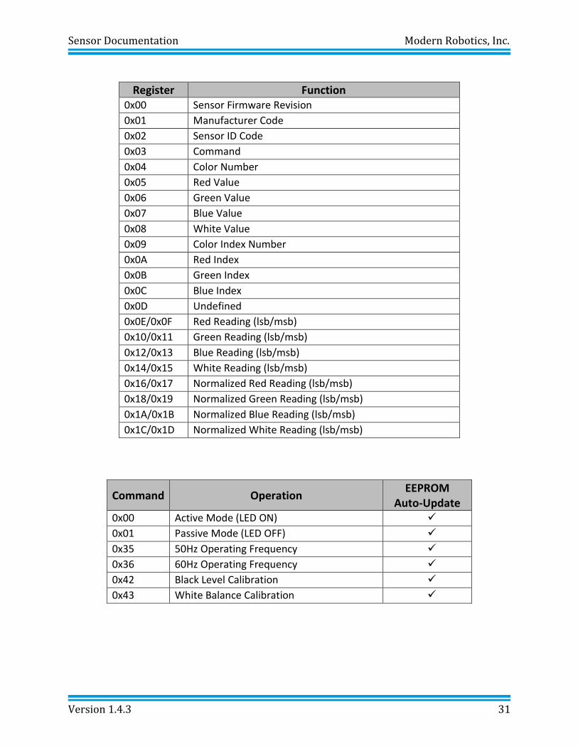
Register Function 0x00 Sensor Firmware Revision
0x01 Manufacturer Code
0x02 Sensor ID Code
0x03 Command
0x04 Color Number
0x05 Red Value
0x06 Green Value
0x07 Blue Value
0x08 White Value
0x09 Color Index Number
0x0A Red Index
0x0B Green Index
0x0C Blue Index
0x0D Undefined
0x0E/0x0F Red Reading (lsb/msb)
0x10/0x11 Green Reading (lsb/msb)
0x12/0x13 Blue Reading (lsb/msb)
0x14/0x15 White Reading (lsb/msb)
0x16/0x17 Normalized Red Reading (lsb/msb)
0x18/0x19 Normalized Green Reading (lsb/msb)
0x1A/0x1B Normalized Blue Reading (lsb/msb)
0x1C/0x1D Normalized White Reading (lsb/msb)
Command Operation EEPROM
Auto-Update 0x00 Active Mode (LED ON) ✓
0x01 Passive Mode (LED OFF) ✓
0x35 50Hz Operating Frequency ✓
0x36 60Hz Operating Frequency ✓
0x42 Black Level Calibration ✓
0x43 White Balance Calibration ✓
Sensor Documentation Modern Robotics, Inc.
Version 1.4.3 32
Commands: The command register may be set to any of the values from the command table. Once a command value is entered into the command register the value will be saved in the EEPROM.
Active Measurement Mode Command = 0x00 In active measurement mode, the sensor takes a reading by illuminating a surface with a white LED and measuring the reflected light. Active mode is useful in identifying the color of a surface. Passive Measurement Mode Command = 0x01 In passive measurement mode, the sensor takes a reading without the white LED on. Therefore passive measurement mode is most useful in determining the color of a light source like an LED. Operating Frequency Command = 0x35(50Hz) or 0x36(60Hz) The operating frequency is provided to enable the sampling to coincide with the normal flickering associated with artificial lighting. This helps to reduce signal noise and other issues. The operating frequency can be set to 50Hz or 60Hz. Black Level Calibration Command = 0x42 Black level calibration will run 64 measurement cycles to obtain an average value for each of the 3 color channels. During black level calibration, the sensor should be placed such that no surface is within 1.5m forward of the sensor elements. The calibration process last about 1.5 seconds and when calibration is complete, the LED will blink briefly and then the command register will be reset to 0x00 or 0x01 depending on the mode save in EEPROM. Black level calibration must be completed before white balance calibration. White Balance Calibration Command = 0x43 White balance calibration will run 64 measurement cycles to obtain and average value for each of the 3 color channels and are adjusted according to the black level calibration values. During white balance calibration, the sensor must be placed approximately 5cm (2in) from a white target. The target must be very white and not allow light to pass through the material. At least 3 sheets of high quality copy paper will make a satisfactory white surface for calibration. The calibration process last about 1.5 seconds and when calibration is complete, the LED will blink briefly and then the command register will be reset to 0x00 or 0x01 depending on the mode save in EEPROM.
Sensor Documentation Modern Robotics, Inc.
Version 1.4.3 33
0 1
2
3
4
5
6
7
8
9
10
11
12
16
13
14
15
0 1
2
3
4
5
6
7
8
9
10
11
12
16
13
14
15
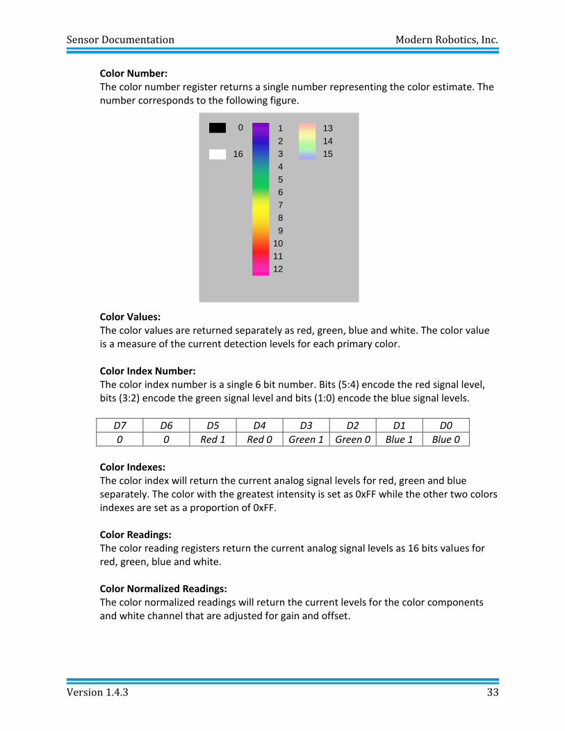
Color Number: The color number register returns a single number representing the color estimate. The number corresponds to the following figure.
Color Values: The color values are returned separately as red, green, blue and white. The color value is a measure of the current detection levels for each primary color. Color Index Number: The color index number is a single 6 bit number. Bits (5:4) encode the red signal level, bits (3:2) encode the green signal level and bits (1:0) encode the blue signal levels.
D7 D6 D5 D4 D3 D2 D1 D0
0 0 Red 1 Red 0 Green 1 Green 0 Blue 1 Blue 0
Color Indexes: The color index will return the current analog signal levels for red, green and blue separately. The color with the greatest intensity is set as 0xFF while the other two colors indexes are set as a proportion of 0xFF.
Color Readings: The color reading registers return the current analog signal levels as 16 bits values for red, green, blue and white.
Color Normalized Readings: The color normalized readings will return the current levels for the color components and white channel that are adjusted for gain and offset.
Sensor Documentation Modern Robotics, Inc.
Version 1.4.3 34
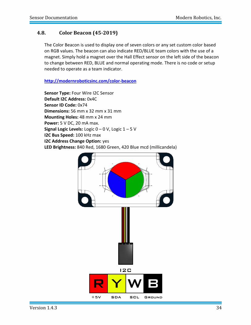
4.8. Color Beacon (45-2019)
The Color Beacon is used to display one of seven colors or any set custom color based on RGB values. The beacon can also indicate RED/BLUE team colors with the use of a magnet. Simply hold a magnet over the Hall Effect sensor on the left side of the beacon to change between RED, BLUE and normal operating mode. There is no code or setup needed to operate as a team indicator. http://modernroboticsinc.com/color-beacon Sensor Type: Four Wire I2C Sensor Default I2C Address: 0x4C Sensor ID Code: 0x74 Dimensions: 56 mm x 32 mm x 31 mm Mounting Holes: 48 mm x 24 mm
Power: 5 V DC, 20 mA max. Signal Logic Levels: Logic 0 – 0 V, Logic 1 – 5 V
I2C Bus Speed: 100 kHz max I2C Address Change Option: yes LED Brightness: 840 Red, 1680 Green, 420 Blue mcd (millicandela)
Sensor Documentation Modern Robotics, Inc.
Version 1.4.3 35
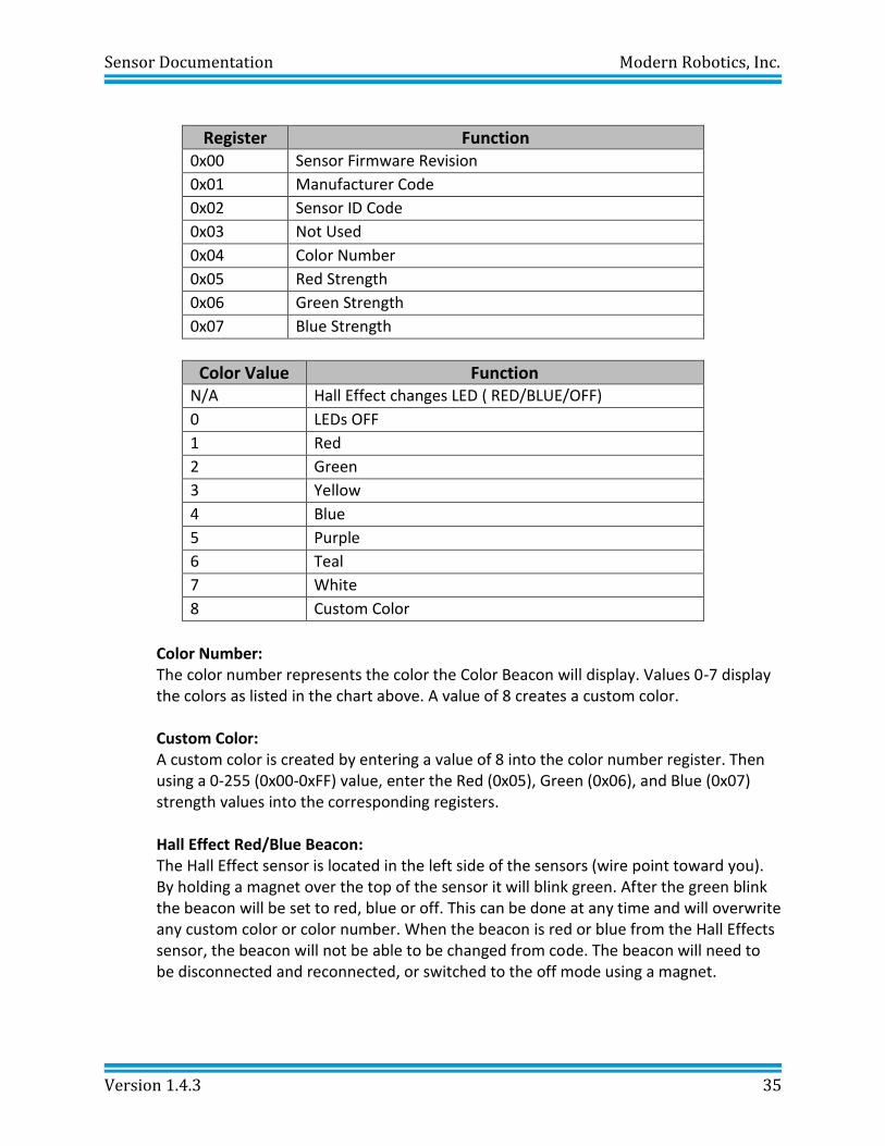
Register Function 0x00 Sensor Firmware Revision
0x01 Manufacturer Code
0x02 Sensor ID Code
0x03 Not Used
0x04 Color Number
0x05 Red Strength
0x06 Green Strength
0x07 Blue Strength
Color Value Function N/A Hall Effect changes LED ( RED/BLUE/OFF)
0 LEDs OFF
1 Red
2 Green
3 Yellow
4 Blue
5 Purple
6 Teal
7 White
8 Custom Color
Color Number: The color number represents the color the Color Beacon will display. Values 0-7 display the colors as listed in the chart above. A value of 8 creates a custom color. Custom Color: A custom color is created by entering a value of 8 into the color number register. Then using a 0-255 (0x00-0xFF) value, enter the Red (0x05), Green (0x06), and Blue (0x07) strength values into the corresponding registers.
Hall Effect Red/Blue Beacon: The Hall Effect sensor is located in the left side of the sensors (wire point toward you). By holding a magnet over the top of the sensor it will blink green. After the green blink the beacon will be set to red, blue or off. This can be done at any time and will overwrite any custom color or color number. When the beacon is red or blue from the Hall Effects sensor, the beacon will not be able to be changed from code. The beacon will need to be disconnected and reconnected, or switched to the off mode using a magnet.
Sensor Documentation Modern Robotics, Inc.
Version 1.4.3 36
5. Controllers Modern Robotics sensors are designed to be used on multiple control devices like the Core Spartan Controller or Core Device Interface Module. The sensors may also be used on any Arduino board, Raspberry Pi, BeagleBone as well as most other types of microcontrollers or embedded systems.
Sensor Documentation Modern Robotics, Inc.
Version 1.4.3 37
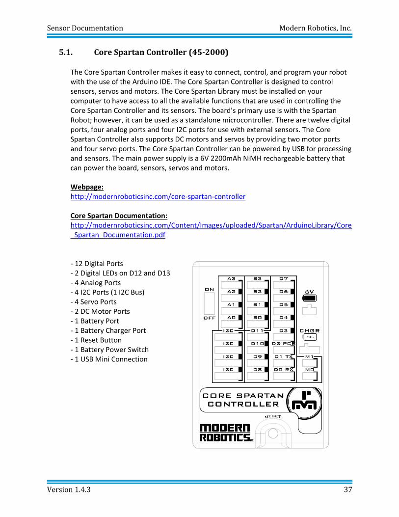
5.1. Core Spartan Controller (45-2000)
The Core Spartan Controller makes it easy to connect, control, and program your robot with the use of the Arduino IDE. The Core Spartan Controller is designed to control sensors, servos and motors. The Core Spartan Library must be installed on your computer to have access to all the available functions that are used in controlling the Core Spartan Controller and its sensors. The board’s primary use is with the Spartan Robot; however, it can be used as a standalone microcontroller. There are twelve digital ports, four analog ports and four I2C ports for use with external sensors. The Core Spartan Controller also supports DC motors and servos by providing two motor ports and four servo ports. The Core Spartan Controller can be powered by USB for processing and sensors. The main power supply is a 6V 2200mAh NiMH rechargeable battery that can power the board, sensors, servos and motors. Webpage: http://modernroboticsinc.com/core-spartan-controller Core Spartan Documentation: http://modernroboticsinc.com/Content/Images/uploaded/Spartan/ArduinoLibrary/Core_Spartan_Documentation.pdf
- 12 Digital Ports - 2 Digital LEDs on D12 and D13 - 4 Analog Ports - 4 I2C Ports (1 I2C Bus) - 4 Servo Ports - 2 DC Motor Ports - 1 Battery Port - 1 Battery Charger Port - 1 Reset Button - 1 Battery Power Switch - 1 USB Mini Connection
Sensor Documentation Modern Robotics, Inc.
Version 1.4.3 38
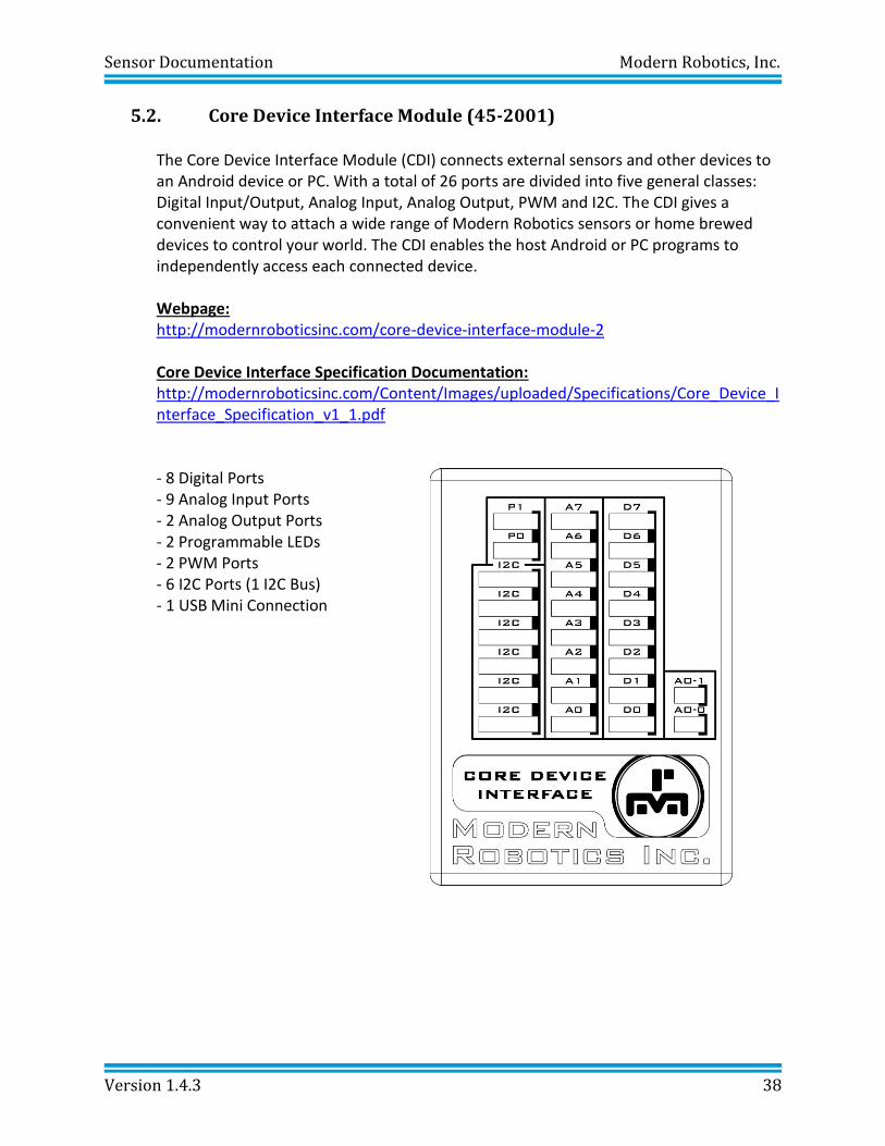
5.2. Core Device Interface Module (45-2001)
The Core Device Interface Module (CDI) connects external sensors and other devices to an Android device or PC. With a total of 26 ports are divided into five general classes: Digital Input/Output, Analog Input, Analog Output, PWM and I2C. The CDI gives a convenient way to attach a wide range of Modern Robotics sensors or home brewed devices to control your world. The CDI enables the host Android or PC programs to independently access each connected device. Webpage: http://modernroboticsinc.com/core-device-interface-module-2 Core Device Interface Specification Documentation: http://modernroboticsinc.com/Content/Images/uploaded/Specifications/Core_Device_Interface_Specification_v1_1.pdf
- 8 Digital Ports - 9 Analog Input Ports - 2 Analog Output Ports - 2 Programmable LEDs - 2 PWM Ports - 6 I2C Ports (1 I2C Bus) - 1 USB Mini Connection