corso g.de gregori,32 13100 - vercelli (vc) - italy +39 ... · progettazione generale e d.l. degli...
TRANSCRIPT

Portfolio
arch.Claudio D’Addato
Corso G.De Gregori,3213100 - Vercelli (VC) - Italy
+39 3293021731 - [email protected] - @
claudio_daddato - Skypearchclaudiodaddato.weebly.com

About me
Architect with experience solving problems in all phases of project development from concept to construction. Extensive experience in precast concrete bearing structures as a quality manager, resolving problems from concept to implementation. Broad experience with construction management and communication with builders during the construction phase.
Experienced project manager skilled in directing multiple tasks and processes simultaneously. Experienced in leading project teams and workgroups.

Engineering
Social Housing - Cameriano - Italy - 2013Riad Black &White - Marrakesch - Morocco - 2012
Antiseismic Steel/Wood Floor In Historical Building - Vercelli - Italy - 2010Prof.Arch.Roberto Roccati - Structural Design Architecture Practice - Job Examples - 2005/2009
Graduation Thesis:“Static And Dynamic Analisys Of Masonry Domes: Study Case: The Dome In Vicoforte (CN)” - 2005
Scientific Publications - 2006
Why to be an archi-engineer? Because I love when the bearing structure become the architecture of the building itself! Because I’m interested in what is behind the appearence of the shape of the architectural design. The structural design is what allow architecture to exist.

2013 - Social Housing - Cameriano - ItalyExisting Building / Masonry Bearing Structure Antiseismic Renovation
New Building / Reinforced Concrete Antiseismic Bearing StructureE
ngin
eerin
g
90150
Via Matteotti
A
90220
120165
150220
9060 120220
120220
90150
B
120220
+ 000
+ 000
EDIFICIO B
A
PIANTA DELLE FONDAZIONIEDIFICIO APIANO DI QUOTA ±0.00
120165
P. 01P. 02
P. 03
P. 04
P. 05
Cordolo
Vespaio Aerato concassero a perdere
tipo igloo
40
40
224
370
Muratura portanteesistente
Aperture: come architravesopra ciascuna apertura
utilizzare 2 HEA 200 dilungh. pari alla luce
dell'apertura + almeno 40 cm(20 cm di appoggio per parte)
381
528
412
536
380 45 414
45
47466
224
45410
489
21545
317110
180
465
47544
300
358
332
457
30
40
30
48040118
6
3015
7
182
30
248
30
537
191125
636
363
97
376
816
1093
1569
579
560
932
1424
Linee di mezzeria
Piastra in ca sp=40 cmarmata con
rete elettrosaldata Ø8/15x15
Cordolo 30x30
Fondazione di consolidamento 40x80 P.06
P. 06
Tramezze internenon strutturali in progetto
310 351
337
Trave di fondazionestruttura metallica
a sostegno del ballatoioPilastro in acciaio
Ø20 smin=5mm
Soletta in caspess (40 cm)
Nuova fondazione per muroperimetrale in progetto
dimensioni pari a 110x40 cmarmata con staffe(104x34) Ø8/20,
4+4 Ø14 a correre
Capo chiave
Consolidamento con intonaco armato
Capo chiave Capo chiave Capo chiave
Ø10 / 20 L=1165
24
242+2 Ø12 a Correre
Ø12 / 20 L=236
5
74
343+3Ø12 a Correre
130
3
5
34
5
Ø16 / 40 L=177
Ø12 / 20 L=236
34
34
5
119
5 5Ø16 / 40 L=129
CARPENTERIA CORDOLI DI FONDAZIONE IN CA E CERCHIAGGIO FONDAZIONIESISTENTI IN MURATURA
130
3
5
34
5
Ø16 / 40 L=177
34
34
5
A R C H I T E T T OFL U C I A E R R A R I S2D E A I A V G O S T I N I N O V A R A
PROGETTO STRUTTURE
PIANO FONDAZIONEedificio A
1: 50
TAV
DICEMBRE 10
PROGETTO EESECUTIVOApprovazione D.G.C. n. 82 del 13.12.2010
Progettazione generale e D.L. degli interventi edilizi
ARCH. LUCIA FERRARISGEOM. CELESTINO VARESI
Progettazione e collaborazione gestionaleservizi socio-assistenziali
C.I.S.A. 24ASL 13 - Novara
ASS. VOL. "NOI PER GLI ALTRI"
UNIONE BASSO NOVARESEComune di CasalinoProvincia di Novara
Regione Piemonte
SPERIMENTAZIONE DI INTERVENTI DI SOCIAL HOUSINGTRAMITE CASI PILOTA
in attuazione della D.G.R. n. 55-9151 del 7.7.2008
CASALINO COMUNE CAPOFILA
REALIZZAZIONE DI N.6 ALLOGGIE SERVIZI SOCIO-ASSISTENZIALI
IN LOCALITA' CAMERIANO
Responsabile Unico del ProcedimentoArch Antonella Ferrari - U.T. Unione Basso Novarese
C:\Documents and Settings\Lucia Ferraris\Documenti\_B_LLPP\HOUSING_Cameriano\DEF\Copia di Progetto1.jpg

2013 - Social Housing - Cameriano - ItalyExisting Building / Masonry Bearing Structure Antiseismic Renovation
New Building / Reinforced Concrete Antiseismic Bearing Structure
Eng
inee
ring

2012 - Riad Black&White - Marrakesh - MoroccoExisting Building / Masonry Bearing Structure
Renovation after fireE
ngin
eerin
g

2010 - Antiseismic Steel/Wood Floor In Historical Building - Vercelli - ItalyExisting Building / Masonry Bearing Structure Antiseismic Renovation
Eng
inee
ring
100260
90 250
90 250
125
250
90170
100260
Connettore tipoTecnariaper solai misti acciaio-cls
Orditura principale formata daprofilati IPE 160 in acciaio Fe360
Muratura in mattoni s=45 cm
REGIONE:
COMUNE:
A.S.L.:
Piemonte
Vercelli
VC
PROVINCIA: Vercelli
PROGETTO: Manutenzione straordinaria appartamento in Vercelli - Via Verdi, 21
COMMITTENTE: Massimigliano LenciVia Feliciano di Gattinara, 713100 / Vercelli
C.F/P.IVA:
Firma:
PROGETTISTA: dott.arch. CLAUDIO D'ADDATOCorso De Gregori, 3213100 / Vercelli
C.F/P.IVA:Tel./email: +393293021731/[email protected]
N°Ordine : 555 (Ordine degli Architetti della Provincia di Vercelli)
DDDCLD78T07L219Q / 02244280026
Firma : __________________
Timbro
Diritti : Questo elaborato cartografico fa' parte integrante del progetto architettonico e strutturale al quale si riferisce; pertanto e' protetto
dalle leggi che tutelano il progetto ed ogni suo utilizzo.
E' vitetato ogni suo utilizzo, anche parziale, non espressamente autorizzato.
__________________
Ogg.Elab.:
ID Tavola:
Carpenteria Solaio in acciaio-cls autoportante e telaio in acciaio
Contenuto:
Data:
LNCMSM74T25L750M
11/11/2009 S1
MASSETTO IN CLS ARMATOCON RETE Ø6 20x20
LAMIERA GRECATA TIPO HI BONDA55/P600 da 0.7 mm
20
15
SEZIONE A-A
IPE 160
66
63
SOTTOFONDO
PAVIMENTAZIONE
CONNETTORE TECNARIA PERSOLAI MISTI ACCIAIO-CLS
FERRO DI COLLEGAMENTO PASSANTEIN ACCIAIO Ø16 OGNI TRAVE L 2O cmAFFOGATA NEL CORDOLO
CORDOLO DI COLLEGAMENTO ARMATOCON 4Ø14 E STAFFE Ø6/20"
16
37
COLLEGAMENTO CORDOLO ALLA MURATURACON 1Ø16 Ltot=50 OGNI 50 cmIN FORO Ø30 SIGILLATO CON MALTA
20
30
FERRO DI COLLEGAMENTO CORDOLO-MURATURA 1 Ø16 OGNI 50 cm
SEZIONE B-B
5.5
66
6
5015
20
PAVIMENTAZIONE
SOTTOFONDO
MASSETTO IN CLS ARMATOCON RETE Ø6 20x20
LAMIERA GRECATA TIPO HI BONDA55/P600 da 0.7 mm
CORDOLO DI COLLEGAMENTO ARMATOCON 4 Ø14 E STAFFE Ø6/20"
IPE 160
55
20
10
COLLEGAMENTO SOLAIO ALLA MURATURACON 1Ø16 Ltot=85 OGNI 50 cm
COLLEGAMENTO SOLAIO-MURATURACON 1Ø16 l=100 cm OGNI 50 cmRIPIEGATO NEL CORDOLO
COLLEGAMENTO CORDOLO ALLA MURATURACON 1Ø16 Ltot=45 OGNI 50 cmIN FORO Ø30 SIGILLATO CON MALTA
15
20
FERRO DI COLLEGAMENTO CORDOLO-MURATURA 1 Ø16 OGNI 50 cm
50
45
Lamiera grecata tipoHI BOND A55/P600/G5 da 0.6 mm
A A
BB
SOLAIO ESISTENTEDIST MIN DAL NUOVO 2,5 CM
SOLAIO ESISTENTEDIST MIN DAL NUOVO 2,5 CM
PARTICOLARE PIANTA
CARPENTERIA SOLAIO IN ACCIAIO-CLS
647653
ESECUTIVO INTERVENTO COLLEGAMENTO NUOVO SOLAIO A MURATURA ESISTENTE
Getto in cls alleggerito strutturale - S = 6 cmCALCESTRUZZO PRATICO LECA CLS 1600
Rete elettrosaldata Ø6 / 20x20 cmla rete deve essere posizionata a non meno
3,5 cm sotto la testa del connettore
Collegamento cordolo-muratura1 Ø16 L=60 cm ogni 50 cm
COLLEGAMENTO CORDOLO ALLA MURATURACON 1Ø16 Ltot=50 OGNI 50 cmIN FORO Ø30 SIGILLATO CON MALTA
30
20Cordolo di collegamento sezcm 15x20 armato con Ø14 e
staffe Ø6/20" inserito nella muratura
MATERIALI UTILIZZATI: ACCIAIO ARMATURA TIPO B450 CACCIAIO PUTRELLE TIPO Fe360CLS ALLEGGERITO STRUTTURALE PREMISCELATOAD ALTA RESISTENZA, LECA CLS 1600 Rck = 35 N/mm²
50
50
135°15
Collegamento angolo-cordoli1 Ø16 L=115 cm ogni angolo
NOTE: Il solaio è autoportante.
Prima del fissaggio del connettore controllare che la lamiera sia aderente al profilo e fissata adeguatamente(eventualmente tramite chiodi dello stesso tipo di quelli usati per il fissaggio del connettore).
Non sovrapporre più di 2 lamiere.
I connettori possono essere fissati anche su due fogli di lamiera sovrapposti(di spessore non superiore a 10/10 mm),purché questi siano ben sovrapposti e adiacenti; se possibile evitare di fissare i connettori su sovrapposizioni.Il connettore va posizionato al centro della nervatura della lamiera.
Se la lamiera ha un irrigidimento centrale posizionare i connettori alternativamente in un lato o nell'altro.
Cordolo di collegamento sezcm 15x20 armato con Ø14 e
staffe Ø6/20" inserito nella muratura
Massetto per passaggio impiantie riscaldamento a pavimento
Pavimentazione al finito
Collegamento alla muratura con1 Ø16 l=100 cm ogni 50 cm
ripiegato nel cordolo (vedi SEZ. B-B)
55
20
10
COLLEGAMENTO SOLAIO ALLA MURATURACON 1Ø16 Ltot=100 OGNI 50 cm
COLLEGAMENTO CORDOLO ALLA MURATURACON 1Ø16 Ltot=45 OGNI 50 cmIN FORO Ø30 SIGILLATO CON MALTA
15
20
Collegamento cordolo-muratura1 Ø16 L=60 cm ogni 50 cm
440 615
5773945050
5050
5050
5050
5050
5050
57
5050
5050
5050
5050
5050
5043
4450
5050
5050
5050
5050
5050
44
3650
5050
5050
5050
5050
5050
60
398 548
Pianta carpenteria di solaio 1:50Particolare pianta - connessione solaio muratura perimetraleSezione A-A'Sezione B-B'
RIF. PRATICA: DIA n° del
SOLAIO 2 SOLAIO 1653

2005/2009 - Prof.Arch.Roberto Roccati - Structural Design Architecture Practice - Job Examples Existing Building / Masonry Bearing Structure Antiseismic Renovation
New Building / Reinforced Concrete Antiseismic Bearing StructureE
ngin
eerin
g
Existing building
New steel storey project
Underground Parking - Pragelato - Italy Stone masonry antiseismic renovation - Lerici - Italy
Antiseismic verification
Structural 3d model
Tensional stresses
Antiseismic verification

2005/2009 - Prof.Arch.Roberto Roccati - Structural Design Architecture Practice - Job Examples Existing Building / Masonry Bearing Structure Antiseismic Renovation
New Building / Reinforced Concrete Antiseismic Bearing Structure
Eng
inee
ring
Existing building
Stone masonry antiseismic renovation - Sarzana - Italy
New steel storey project
Antiseismic verification
Structural 3d model
Tensional stresses
Antiseismic verification
Stone masonry antiseismic renovation - render - Lerici - Italy

2005 - Graduation Thesis: “Static And Dynamic Analisys Of Masonry Domes: Study Case: The Dome In Vicoforte (CN)”Masonry Bearing Structure / Antiseismic Active Control
Eng
inee
ring
Existing building Existing buildingStructural 3d model Structural 3d model

2005 - Graduation Thesis: “Static And Dynamic Analisys Of Masonry Domes: Study Case: The Dome In Vicoforte (CN)”Masonry Bearing Structure / Antiseismic Active Control
Eng
inee
ring
Structural 3d model
Dome tensional stresses
Tensional stresses
Tensional stresses
Sacrestia
II cornicione
Estradosso cupola
Lanterna
Asse X positivo
Asse Y positivo

2006 - Scientific PublicationsMasonry Bearing Structure / Antiseismic Active Control
Eng
inee
ring

Structural Analysis of Historical Constructions, New Delhi 2006 1 P.B. Lourenço, P. Roca, C. Modena, S. Agrawal (Eds.), ISBN 972-8692-27-7
1 INTRODUCTION
The Sanctuary of Vicoforte, near Mondovì (Cuneo, Italy), is a building of great historical, ar-chitectural and structural significance and owes its fame primarily to its great elliptical masonry dome (Figs. 1a-b), which is the fifth biggest in the world (after the Pantheon, Saint Peter and S. Maria del Fiore in Italy, and Gol Gumbaz Mausoleum in India) in terms of overall dimensions. With its 37.15 m and 24.80 m long axes, it is also by far the largest elliptical dome the world over.
Originally conceived by the Duke Charles Emanuel I of Savoy as the mausoleum of the dy-nasty, the Sanctuary began to be constructed in 1596 by architect Ascanio Vittozzi. Since the earliest stages of construction, the building was adversely affected by important differential set-tlements of the foundations due to an unfortunate selection of the site, and remained almost abandoned for more than one century. The shallow baroque ribbed dome was erected only in 1732 − after the monument had lost its original role as a mausoleum of the royal family − on top of a slender drum completed in the preceding years.
Monitoring and modelling strategies for the world’s largest elliptical dome at Vicoforte
Mario A. Chiorino, Roberto Roccati and Claudio D’Addato Politecnico di Torino, Department of Structural and Geotechnical Engineering, Torino, Italy
Takayoshi Aoki Nagoya City University, Nagoya, Japan
Chiara Calderini University of Genoa, Department of Structural and Geotechnical Engineering, Genoa, Italy
Alberto Spadafora Politecnico di Torino, CESMO, Mondovì, Cuneo, Italy
ABSTRACT: With its internal axes of 37.15 by 24.80 m, the Vicoforte dome is the fifth biggest dome in the world and by far the largest elliptical one. The dome-drum system has suffered since the beginning from significant structural problems, related in part to soil settlements, and, to a large extent, to the daring structural configuration. The paper deals with the monitoring and modelling strategies adopted in recent years following the strengthening intervention oper-ated in 1985 with the application of active tie-bars around the perimeter at the top of the drum.
Figure 1: External (a) and internal (b) view of the Sanctuary. Cracks in the dome (c): north-south section; view of the west side (Garro 1962).

2 Structural Analysis of Historical Constructions
Figure 3: Modern strengthening system.
The dome-drum system has suffered since the beginning from significant structural prob-lems, related in part to the additional settlements induced by the new built masses, and, to a large extent, to the daring structural configuration of the system itself. In fact, the extended network of cracks that affects a large portion of the building becomes particularly severe in the dome-drum region (Figs. 1c and 2a), where the cracks are oriented along the typical meridian directions with maximum openings at window locations and an increased density next to the buttresses. Cracks extend over a large portion of the meridians and spread up to the summit of the dome, the largest meridional crack, at the oval window on the west side, almost reaching the base ring of the top skylight lantern. Its maximum width is 4.8 cm, and the sum of crack widths along the perimeter exceeds 40 cm. Important oblique cracks near the openings of the buttresses result from shear stresses induced by the radial thrusting action of the dome (Fig. 2b).
In 1985, concerns over such severe cracking configuration, with particular regard to possible
yielding or rupture of the original three levels of circumferential iron rings located in the transi-tion region between dome and drum, prompted the decision to undertake monitoring and strengthening works. A system of 56 active tie-bars, slightly stressed by jacks, was applied (1987) within the masonry at the top of the drum along 14 tangents around the perimeter (Fig. 3), and a complex monitoring system was set up to measure movements of the structure and propagation of cracks, as well as stresses in the reinforcing tie-bars (re-tensioned in 1997).
In recent years a new project was started for a thorough renovation of the monitoring system and the updating of the structural models originally adopted to explore the static configuration and integrity of the construction and define the characteristics of the strengthening system.
The paper presents the general lines and the preliminary results of this new research pro-gram aimed to set on new advanced bases the general preservation and protection plans for the monument, in particular in what concerns the structural aspects.
North East West South
Figure 2: (a) Crack distribution and total settlements along the perimeter; maximum differential settlements (W vs. NE) ca. 30 cm. (b) Diagonal shear cracks in the buttresses (Garro 1962).

T. Aoki, C. Calderini, M. A. Chiorino, C. D’Addato, A. Reffo, R. Roccati, and A. Spadafora 3
2 THE NEW MONITORING SYSTEM
The new monitoring system is a technologically upgraded version of the instrumentation in-stalled during the dome strengthening works of 1985-87. The goal of the monitoring process is to study the evolution of damage conditions and to identify the phenomena that caused them. The instruments used can be classified into two groups, i.e., tools for the measurement of strains, cracks and states of stress in the structure, and tools for measuring the boundary and ambient conditions. The first group includes 10 strain gauges applied to the main cracks at the impost of the dome and to the biggest west crack at the extrados; 20 horizontal pressure cells, for the determination of stress variations in the eight pillars and the buttresses; another cell, ar-ranged vertically near the top of the dome above the main meridian crack, is used to determine the circumferential compression stress; 56 load cells are situated at the ends of the active cer-clage bars to control their stress conditions; 2 pairs of stainless and invar wire gauges at the im-post of the dome are used to assess the overall geometry of the structure, and 12 nails are pro-vided for additional manual measurements of convergence. The second group includes: 1 hygrometer and 25 mechanical thermometers, 17 of them located inside the walls and 8 exter-nally; 3 piezometric electric cells for monitoring the ground water level; 1 hydrometer for monitoring the water level in the drainage pipe collection tank. The entire monitoring system is managed by a PC working as a central acquisition system that enables the data obtained to be processed and transmitted in remote mode.
A dynamic monitoring system, presently under consideration, consisting of 10 tri-axial ac-celerometers to be placed along the main axes at significant points will enable to record the structural response to seismic events, even low-magnitude ones, and to ambient micro-tremors. It will provide a data-base for future analyses in the seismic domain and for the procedures of validation and updating of the numerical models.
Some considerations can already be formulated from the data collected during the first 17 months. Convergence measurements and stress values in the active cerclage bars evidence that seasonal temperature variations constitute the primary cause of variability of the data. In par-ticular, thermal expansion phenomena during the hottest periods are accompanied by a consid-erable reduction in the stress level in the active tie-bars. Some strain gauges detect a slight in-crement in the dimensions of some cracks, which, however, does not exceed one tenth of mm per year. Aside from these normal fluctuations, the measurements recorded by the various in-struments can be presently rated as substantially stable. When the time horizon of the monitor-ing process will be long enough, it will be possible to explore the existence of a correlation be-tween structural parameters and the variations in the boundary and ambient conditions.
3 DIAGNOSTIC INVESTIGATIONS
Diagnostic investigations were performed in the past years to characterise the foundation soil and the masonry structure. Geotechnical studies were conducted in two stages: the first cam-paign, carried out in 1976, consisted of 13 geotechnical surveys followed by laboratory tests on undisturbed soil samples. The surveys covered a vast area, inside and outside the Sanctuary, and were accompanied by the drilling of 29 bore holes at the base of the masonry structure through the foundations. As revealed by these investigations, a layer of marl declining in the south-west direction is situated from 3 to 9 m below the surface level. The foundation struc-tures in the south-west zone of the monument, especially those of the pillars supporting the dome-drum system, rest on a silt-clay layer reaching a maximum thickness of 3 m (Fig. 4a).
The second campaign, carried out in 2004, coincided with the installation of the 3 electrical piezometric cells of the new monitoring system. It included 4 geotechnical surveys, each of which collected 5-6 undisturbed soil samples that were subjected to tests; 2 cross-hole seismic geophysical tests were performed in the bore holes for the determination of the velocity pro-files of shear and compressive waves (S and P waves, respectively) in stratified media (Figs. 4a-c). On the basis of the available field and laboratory investigations a geotechnical characteri-zation of the subsoil was carried out. The bedrock formation has on average a very high strength and very low deformability, and therefore, from the geotechnical point of view, it can be considered as a rigid support for the upper formation. The latter is slightly over-

4 Structural Analysis of Historical Constructions
consolidated, mainly due to seasonal oscillations of the groundwater, desiccation phenomena and, possibly, superficial loads applied and removed locally within historical times.
As for the mechanical properties of the masonry, the following average data were obtained
from compressive tests on masonry blocks taken from the building (Barosso 1979): - Young’s modulus: 1500 N/mm2, - compression strength: 3 N/mm2.
In 2004, non-destructive tests (NDT) were performed to evaluate the compressive strength and Young’s modulus of the mortar and bricks by means of a scratch tester (scratch width) and a Windsor Pin System (penetration resistance). These tests were accompanied by compression tests on small brick and mortar cylinders (φ 33 mm x 50 mm) performed according to Japanese Standards JIS A 1108. Good correlations were found between the outcomes of two NDT tests and between these tests and the compression tests. In particular, as scratch width gets larger, penetration resistance and compressive strength decrease. On the other hand, as penetration re-sistance increases, compressive strength becomes greater. The relationship between compres-sive strength and Young’s modulus is fairly linear (Aoki et al., 2004b).
4 MODELING STRATEGIES
Different analyses were performed with the finite elements method, using various material and structural models with different levels of sophistication, focusing on different aspects of the structural response. The results obtained from such models were also compared with the re-sults of a limit state analysis for a rigid no-tension material.
The first step was the construction of a solid model (Fig. 5) reproducing as faithfully as pos-sible the complex geometric characteristics of the structure of the whole monument, to be used as the basic term of reference for the construction of models having, in some cases, a simpler geometry or a more limited extension, and hence suitable for more complex investigations, in particular in terms of constitutive laws of the materials and of the domain of analysis. The ref-erence model was created on the basis of a general structural topographic survey, completed in 2004, extended to the entire monument with the exception of the dome. The geometry of the dome was defined on the basis of the 1976 photogrammetric survey of its interior surface and of direct inspections for the determination of its thickness. .
4.1 Linear-elastic FEM analysis of the entire undamaged building
Based on the reference solid model, a FEM model of the entire monument was produced, con-sisting of ca 10000 20-node brick elements and 580 8-node shell elements, with a total of ca 193000 degrees of freedom. As a first step, a series of elastic analyses of the entire undamaged building were performed, with the aim of obtaining a preliminary rough description of the overall structural behaviour. Different analyses were undertaken in order to estimate the influ-ence of different structural elements such as the old annular reinforcement and the recent strengthening bars, or the lantern at the top of the dome (Spadafora 2002, Aoki et al. 2004a).
Figure 4: (a) Axonometric view of foundations and foundation layers. Cross-hole test: (b) P-wave and S-wave velocity profile; (c) tomographic data elaboration.

T. Aoki, C. Calderini, M. A. Chiorino, C. D’Addato, A. Reffo, R. Roccati, and A. Spadafora 5
Figure 6: Deformed shapes and maximum principal stresses of dome and drum at the cross section along minor axis, without (a) and with (b) original iron rings.
Figure 5: Solid FEM reference model.
The results in terms of principal stresses show rather clearly that the skeleton of the building is essentially made up of the eight pillars, the buttresses above them and the ribbed segments of the dome. These structural components are responsible for transferring the dead weight of the structure to the ground; at the same time they serve as stiffening elements that counter the radial thrusts of the dome.
Interesting results are obtained in what concerns the states of strain and stress in the dome-drum system, the general response of the structure depicted by the model resulting in fairly good agreement with the experimental observations and the observed damages. In particular, significant tensile stresses are produced in the model at the dome impost level. These stresses are strong enough to generate sub-vertical cracks, especially in the proximity of the oval win-dows (higher values at E and W on the minor axis), i.e., at the weakest points in the dome. The upper part of the drum appears to be pushed outwards by the radial thrusts of the dome, which causes the widening of the dome oval at the impost level, especially in the section along the minor axis where a narrowing of the oval at the base of the drum is also detected. The original iron rings (locations in Fig. 9) reduce both hoop stresses and widening of the oval (Fig. 6a-b), resulting particularly effective, as confirmed by the limit analysis reported at section 4.4. Their integrity in the real structure is currently being investigated. The distribution of the principal stresses in the buttresses denotes the presence of a shear action consequent to the outward de-formation of the drum, justifying the observed diagonal cracks in the structure.
The FEM model also evidences the effect of the weight of the skylight lantern on the state of stress of the dome. This load enhances the circumferential tensile stresses at the impost of the dome and the tri-axial compressive stresses around to top crown circle of the dome.
A shell model limited to the dome-drum system was also produced. This model, character-ised by a reduced computation burden, is essentially conceived for a use with more sophisti-cated material constitutive laws of anisotropic non-linear type, as indicated at section 4.3. On the other hand, the model incorporates a more refined description of some structural elements with respect to the general model, taking into account e. g. the cylindrical cavities present in the four buttresses adjacent to the major axis, and subdividing the dome-drum system in its main

6 Structural Analysis of Historical Constructions
structural components, in order to be able to distinguish the individual behaviour of each. In a preliminary stage also this second model was associated to a pure elastic analysis. The results substantially confirm the outputs of the elastic analysis based on the general solid model.
4.2 Linear-elastic FEM analysis of the damaged dome-drum system
The principal feature of this model consists in the simulation of the main cracks observed in the structure through the creation of geometric discontinuities at the eight most important le-sions. An effort was also done to make the numerical model as “light” as possible during the computation stage, and as “legible” as possible at the stage of interpretation, adopting a con-venient blend of shell and beam elements, having regard to the specific geometric and struc-tural characteristics of the portions under consideration (shell elements for the dome and bear-ing walls with curved geometry, beam elements for arches and pillars). Doing so, a special attention was devoted to some specific zones of architectural-structural relevance, as e. g. the transition region from the drum to the dome characterized by a reverse arch connecting the haunches of the dome to the drum. On the other hand the structures below the drum were rep-resented rather schematically. The original iron rings were modeled as one-dimensional elastic elements; the aim of the investigation being the exploration of the static configuration of the monument before the recent strengthening intervention, the influence of modern tie-bars was disregarded. The analysis was performed in the linear elastic domain (D’Addato 2005).
The analysis of the results shows that the principal compressive stresses of the vault develop along the meridians and become tangential to the lantern impost oval, where the compressive stresses are tri-axial. The principal tensile stresses develop along the parallels and circumvent the cracks by assuming a 45° slant, and then concentrate at the bottom of the lesion, generating the “notch effect”, i.e., the tendency of the lesion to propagate through the undisturbed ma-sonry (Fig 7a). The tensile stresses that have generated the cracks reappear in the segments be-tween one main crack and another; the state of stress supplied by the model is in good agree-ment with the actual cracking configuration.
One interesting output of the analysis is represented by the estimation of the opening of the
pre-established cracks at the base of the dome. The biggest width, of 7 cm, is associated with the crack having the longest vertical development located at the oval window on the west side, while the values of secondary cracks range from ca 4 to 5 cm (Fig. 7b). These values should not be compared with the maximum amplitudes of the cracks observed at the same level in the real structure (4.8 cm for the west crack). Rather, the comparison should be performed with the sum of the crack openings registered in the corresponding sectors of the real structure, which range from 2.9 cm to 8.2 cm, with an average of 5.2 cm for the 8 sectors corresponding to the 8 oval windows.
dLy = 2 cm W dLx = 7 cm max crack opening
dLy = 2 cm E dLx = 6 cm
S dLy = 3 cm dLx = 3 cm
N dLy = 3 cm dLx = 3 cm
dLy = 3 cm dLx = 3 cm crack opening 4 cm
dLy = 3 cm dLx = 3 cm crack opening 4 cm
dLy = 3.5 cm dLx = 3.5 cm
crack opening 5 cm
dLy = 3.5 cm dLx = 3.5 cm crack opening 5 cm
Total crack opening: 37 cm
Figure 7: Principal stresses (a) and deformations (b) of the cracked dome.

T. Aoki, C. Calderini, M. A. Chiorino, C. D’Addato, A. Reffo, R. Roccati, and A. Spadafora 7
4.3 Damage FEM analysis of the dome-drum system
The model concerns only the dome-drum system. An anisotropic damage model for the ma-sonry under plane stress (Calderini and Lagomarsino 2006) is employed. It considers different in-plane damage mechanisms, involving both mortar joints and blocks. The model is imple-mented in 4-nodes non-linear shell elements with transverse shear strain capability (ANSYS). Thus, except for the original tie-rods, the entire structure is modelled by mean of shell ele-ments. The description of the masonry geometrical pattern is obtained through the orientation of the local coordinate system of the elements. In particular, the surface of the dome-drum sys-tem is modelled considering its internal system of relieving arches.
Two different analyses were performed: in the first one, only gravity loads were considered; in the second, the additional effects of the foundation differential settlements were studied. Af-ter a reasonable estimate of the amount of settlements occurred subsequent to the completion of the dome, on the basis of historical notes and of recent surveys, the corresponding values were applied as vertical displacements at the base of the drum. The non linear damage model, while confirming in general the structural interpretations derived from the other models, evi-dences some specific features associated with the non-linearity and anisotropy of the masonry.
Internal view
South West North East
External view
Figure 8: Non linear damage analysis: principal inelastic strains considering foundations settlements. In particular, it is worth noting that, if only gravity loads are considered, inelastic strains and
failures denoting the formation of cracks are concentrated at the base of the dome, in corre-spondence of the oval windows and of the relieving arches, and in the drum above and below the triple windows (more intensely, in all cases, along the major sides of the monument per-pendicular to its minor axis). In fact, in these regions, besides the concentration of the horizon-tal tensile hoop stresses acting orthogonally to the masonry head joints, due to the presence of the openings as already noted in the linear elastic FEM analysis of the undamaged building, the meridional compressive stresses on the bed joints of the masonry are very low, and thus the friction contribution to the strength with respect to horizontal stresses is limited. One other cause favouring damage mechanisms is represented by the presence of the arch rings of the oval openings and of the relieving arches above the triple windows of the drum, implying the presence of mortar bed joints nearly orthogonal, in the crown regions, or significantly inclined with respect to the circumferential tensile stresses acting on the structure.
If the differential settlements of the foundations are considered as well, although the role of the various structural elements and the damage mechanisms remain basically the same, the damage state appears to be more severe and becomes asymmetric. The West side of the dome, characterised by the higher values of differential settlements, appears to be significantly more damaged than the East side, and the same applies, with less difference, to the North and South

8 Structural Analysis of Historical Constructions
faces, respectively (Fig. 8), with a close relation to the crack distribution observed on the real structure (Figs. 1c and 2a). A detailed description of the non linear damage analysis can be found in the parallel paper by Calderini et al. (2006). Further researches on soil-structure inter-action in an historical perspective and with reference to the recent campaign of geothechnical investigations are presently under way.
4.4 Limit state analysis of the dome-drum system
A synthetic approximate estimation of the safety conditions of the dome-drum system may be obtained by limit state analysis introducing the simplifying assumption that considers masonry as a rigid material with no resistance to tensile stresses. The principles of this type of analyses based on extremum theorems of the theory of plasticity (static or kinematic approach) and the criteria for their application to masonry domes have been well established by Heyman (1977, 1988) and Oppenheim et al. (1989).
Although affected by some fundamental conceptual and/or computational errors that have undermined the validity of the results obtained at the time, these approaches were already adopted in the 18th century debate on the structural integrity of St. Peter’s dome, namely by the Tre Mattematici in 1742 (kinematical approach applied to the dome-drum system with errors in the definition of the most efficient rigid body collapse mechanism and in the related computa-tions) and in 1748 by Poleni (static approach erroneously limited to the sole dome).
The limit state analysis for the rigid no-tension material rests on the concept that masonry structures achieve their structural integrity through their geometry by providing, with adequate geometrical margins, a funicular load path to the ground without any contribution of tension stress fields (static approach), or, equivalently, by providing an adequate degree of stability for the most efficient rigid body collapse mechanism (kinematical approach). Rather seldom these conditions are reached in the case of domes, if the consideration is limited to the pure masonry. In fact, in most cases the obtainment of a safe funicular path, or equivalently of a stable rigid body configuration, is not guaranteed by the slender geometry of the dome-drum systems, af-fected by high symbolic values, normally found in the architectures of the Christian era. Rather, structural integrity generally requires the contribution of the tension stress field pro-vided by the system of iron cerclage rings, and of the buttressing architectural elements.
The problem can be reduced to a two dimensional case by conservatively admitting, coher-ently with the assumption of absence of tensile strength of the masonry, the full development of meriodional cracks evenly spaced along the perimeter, and consequently dividing the dome and the drum into lunes (vertical slices equivalent to half arches with varying cross section for the dome portion) of limited angular width. Doing so, it is apparent that the stabilizing contri-bution of buttresses is ignored, the evaluation of the structural stability being restricted to the isolated lune element. On the other way, the tensile contribution of the circumferential iron rings can be accounted for; if the kinematical approach is adopted, this contribution results from the plastic dissipation that takes place because of the circumferential expansion the rings are subjected to during the development of the mechanism.
This last approach was used in the case of Vicoforte dome-drum system extending its do-main of application from the domes of revolution, to which it was originally applied, to the case of an elliptical dome (Reffo 2002). The two extreme cases of lunes ideally cut by merid-ional planes in correspondence of the minor and major axes of the base ellipse were conse-quently considered, taking into account the voids produced in the masonry mass by the large windows in the drum and the dome. The presence of the skylight lantern was considered only in terms of applied weight at the top of the lune with reference to its angular width, disregard-ing by way of approximation the spatial interaction between sectors of the dome of different deformability characterising the elliptical configuration. The approach consists of trying to identify the most probable collapse mechanism for each of the two extreme lunes and the rela-tive safety levels through the principle of virtual works.
The typical mechanism through which the dome-drum half-arches reach collapse envisages the formation of three plastic hinges, arranged alternatively at the extrados and the intrados, and the presence of an uncracked zone at the top of the dome, which translates in the vertical direction only. In the case of Vicoforte dome the most efficient mechanism was found by a specifically programmed iterative procedure determining, by trial and error, the optimum posi-

T. Aoki, C. Calderini, M. A. Chiorino, C. D’Addato, A. Reffo, R. Roccati, and A. Spadafora 9
tion of the plastic hinges. Lunes of the dome and drum of 1° of amplitude were considered and they were divided in vertical thin finite elements.
The safety of the pure masonry lunes was first explored, ignoring the presence of the iron cerclage rings. It was found that the stability is not guaranteed, the resisting virtual works being significantly inferior to the pushing works for the most efficient mechanisms, especially for the slender and flat lune along the major axis. This is due to the particular slenderness of the drum, and, above all, to the excessive voids produced in the resisting masonry masses by the large windows of the drum and the dome. The application of the static approach provides a check of these results showing the impossibility to locate any thrust line within the geometrical bounda-ries of the two lunes. It is therefore shown that if the attention is conservatively focused on the sections without buttresses (extending over more than 70% of the total development) the stabil-ity can be guaranteed only accounting for the contribution of a cerclage system. If the presence of the original iron rings (total cross section of 140 cm2) in their well selected favorable posi-tions is considered (Fig. 9; a = b = 56 cm2, c = 28 cm2), adopting once again the kinematical approach and assuming a yield strength for the iron of ca. 170 Mpa, together with an assump-tion of sufficient ductility, adequate safety margins can on the contrary be restored, the mini-mum ratio Lr/Lp between resisting and pushing virtual works amounting to 1.49 for the section along the major axis and to 2.63 along the minor axis (Fig. 9). Figure 9 allows also appreciating the beneficial stabilizing effects of the masonry masses of the tiburio below the reverse arch marking the extrados of the dome, as they are located at the left hand side of the centers Ci of instantaneous rotation of the dome element. However, it should be noted that in the real struc-ture they are affected by the presence of some voids, not considered in the calculations.
Although these results were obtained through the schematic and partially conservative model
of the rigid no-tension material for masonry, the emphasis they place on the role of the original cerclage brings further justification to the investigations currently under way on their structural integrity and prompts a positive evaluation of the strengthening intervention performed in 1985-87 through the application in d of the active tie-bars (Fig. 3) along the perimeter, and of the re-tensioning operated in 1997, which appear as appropriate safeguard measures.
5 CONCLUSIONS
From a comparison of the results of the different mathematical models the following conclu-sions can be reached: − the primary causes of the structural damage that has affected the dome-drum system of the
Sanctuary of Vicoforte are its daring structural configuration and the differential settlements of the foundations occurred after the completion of the dome;
Figure 9: Determination of the minimum ratio Lr/Lp between resisting and pushing virtual works.
δc
δa
δb
b
c
a
Lr/Lp = 1,49
Ci
N-S section along major axis
d
δc
Ci
δa
δb
b
c
a
Lr/Lp = 2,63
E-W section along minor axis
d
10 Structural Analysis of Historical Constructions
− the first cause generated a network of meridional cracks, distributed over the entire perime-ter, accompanied by diagonal shear cracks in the buttresses; the second cause resulted in more significant damages, enhancing the cracks due to the first cause in the zones most af-fected by differential settlements;
− the structural integrity of the dome and the drum relies consistently on the confining effect of a cerclage system. The combination of these results with the data obtained from diagnostic investigations and
monitoring allows to formulate hypotheses and outline possible scenarios and strategies regard-ing the structural preservation conditions of the monument. It permits to identify phenomena, structural components and indicators that have to be monitored to be able to evaluate the evo-lution of the structural integrity conditions. Due to the central role played by cerclage, monitor-ing of the new system of tie bars is mandatory, while significant information may derive from investigations on the integrity of the original iron rings. From a comparison between the cur-rent monitored data with those recorded before the 1985-1997 strengthening intervention, it seems clear that this intervention proved effective. On the other hand, geognostic surveys de-scribe a foundation soil so well consolidated that, assuming the hydro-geological conditions remain stable, the occurrence of further settlements of the foundations, and hence further dam-age to the masonry, can be ruled out. Dynamic monitoring, presently under study, will offer valuable opportunities for the validation of current models and the seismic assessment of the monument.
REFERENCES
Aoki, T., Chiorino, M.A., Roccati, R. and Spadafora, A. 2004a. Structural analysis with F.E. method of the elliptical dome of the Sanctuary of Vicoforte. Proc. First Intern. Conf. Innovative Materials and Technologies for Construction and Restoration – IMTCR04, p. 417-429. Naples: Liguori.
Aoki, T., Komiyama, T., Tanigawa, Y., Hatanaka, S., Yuasa, N., Hamasaki, H., Chiorino, M. A. and Roc-cati, R. 2004b. Non-destructive Testing of the Sanctuary of Vicoforte. Proc. of 13th International Brick and Block Masonry Conference, Vol.4, p.1109-1118. Amsterdam.
Barosso, L. 1979. The dome-drum structure of the Sanctuary of Vicoforte: materials and construction techniques (in Italian). Turin: Atti e Rassegna Tecnica della Società degli Ingegneri e degli Architetti di Torino
Calderini, C. and Lagomarsino, S. 2006. Non linear modelling of masonry structures under cyclic loads. In C.A. Mota Soares et. al. (eds), III Europ. Conf. on Computational Mechanics, Lisbon, CD-ROM.
Calderini, C., Chiorino, M.A., Lagomarsino, S. and Spadafora, A. 2006. Non linear modelling of the ellip-tical dome of Vicoforte. V Int. Conf. on Structural Analysis of Historical Constructions. New Dehli.
D’Addato, C. 2005 Static and dynamic analysis of monuments: the Sanctuary of Vicoforte (in Italian). Graduation thesis, Roccati, R. and Chiorino, M. A. tutors. School of Architect., Politecnico di Torino.
Garro, M. 1962. The Sanctuary of Vicoforte: strengthening and rehabilitation works (in Italian). Technical report. Cuneo. Heyman, J., 1977. Equilibrium of shell structures. Oxford: Clarendon Press. Heyman, J. 1988. Poleni’s problem. In Proc. Inst Civ. Engrs. 84, p. 737-759. Le Seur, T., Jacquier, F and Boscovich, R. G. 1744. Parere di tre mattematici sopra i danni che si sono tro-
vati nella cupola di S. Pietro, Sul fine dell’Anno 1742, dato per ordine di Nostro Signore Benedetto XIV (Opinion of three mathematicians on the damages observed in St. Peter’s dome at the end of the year 1742, given by order of Our Lord Benedict XIV; in Italian). In Scritture concernenti i danni della cupola di San Pietro di Roma e i loro rimedi (Writings on the damages of St. Peter’s dome and related remedial measures), Venice.
Oppenheim, I.J., Gunaratnam, D.J. and Allen, R.H. 1989. Limit state analysis of masonry domes. In Jour-nal of Structural Engineering 115 (4), p. 868-882.
Poleni, G. 1748. Memorie istoriche della gran cupola del Tempio Vaticano (Historical notes on the great dome of the Vatican Temple; in Italian). Padova.
Reffo, A. 2002. Limit analysis of large masonry domes: the dome of the Sanctuary of Vicoforte (in Ital-ian). Graduation thesis, Chiorino, M. A. tutor. School of Architecture, Politecnico di Torino.
Spadafora, A. 2002. Finite element analysis of the Sanctuary of Vicoforte (in Italian). Graduation thesis, Chiorino, M. A. tutor. School of Architecture, Politecnico di Torino.

ArchitectureVilla - Caresanablot - Italy - 2013
Villas - Malindi - Kenya - 2013Main Office - Tourism Agency - 2012
Condo Apartment - Milan - Italy - 2012Villas - Caresanablot - Italy - 2012
Loft - Milan - Italy - 2011Loft - Turin - Italy - 2010

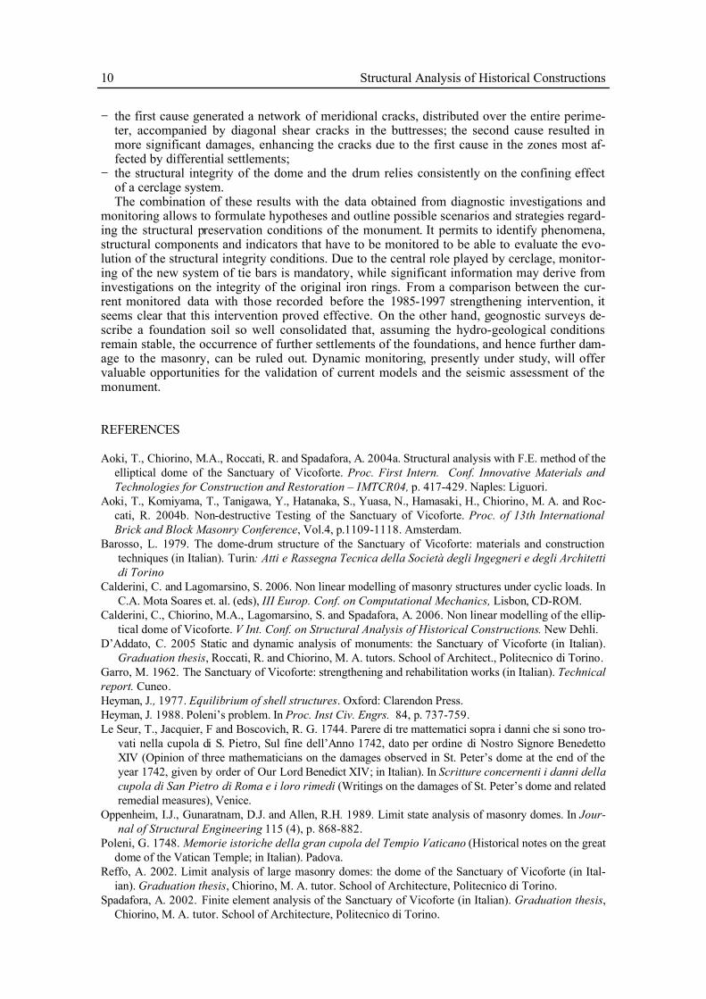
2013 - Villa - Caresanablot - ItalyArchitectural project / Structural design project
ConstructionA
rchi
tect
ure
2013 - Villa - Caresanablot - ItalyArchitectural project / Structural design project
Construction
Arc
hite
ctur
eDetailing

2013 - Villas - Malindi - KenyaArchitectural project / Structural design project
Arc
hite
ctur
e
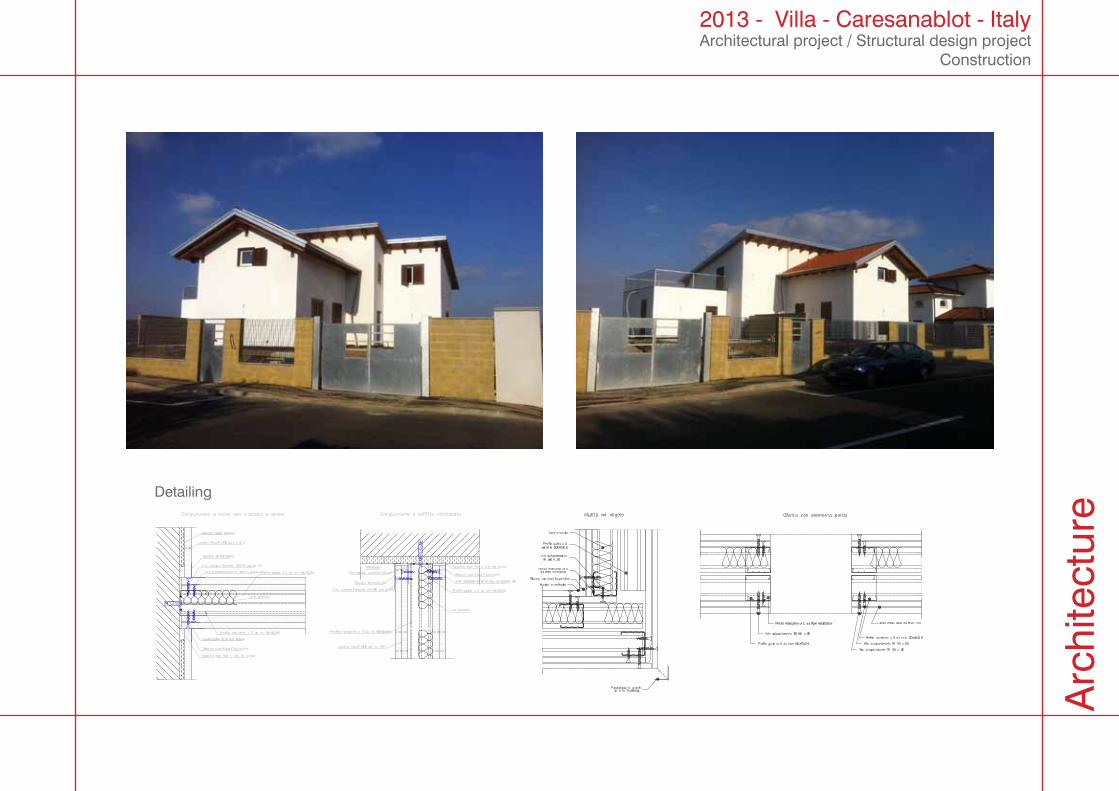
2012 - Main Office Tourism Agency - Milan - ItalyArchitectural project
Construction
Arc
hite
ctur
e
210
80
21060
210120
290
346
340
SU
210
140
21080
210
70 210
70
21090
21090
21090
210
70
21060
21060
21060
21060
21060
21080
346
OPERE DI RISTRUTTURAZIONE EDIFICIO DIREZIONALEHOTELPLAN ITALIA - SEDE DI MILANO, C.so Italia 1
FORMAZIONE NUOVA AGENZIA VIAGGIO, SALAPOLIFUNZIONALE E UFFICI OPERATIVI
SCHEMA DI UTILIZZO
- PIANO INTERRATO: SALA POLIFUNZIONALE- PIANO TERRENO: AGENZIA VIAGGI / BIGLIETTERIA- PIANO SECONDO: AGENZIA VIAGGI / UFFICI
Team architect:
Elaborato I Drawing Item
REGIONE LOMBARDIAPROVINCIA DI MILANO
COMUNE DI MILANO
PROGETTAZIONE E DIREZIONELAVORI OPERE ARCHITETTONICHE
Scala I Scale
09_011Giugno 2011
Elaborato No. I Drawing No. Tavola n.
AGGIORNAMENTI I UP DATEN° DATA I DATE
* Riservato all'Amministrazione
Progetto I Project
PROGETTO PRELIMINARE
STEFANO TARDITO IARCHITETTO
iscritto all'Ordine degli Architetti dellaProvincia di Vercelli al n° 548 Sez. A
Via Verdi 2713100 VERCELLI - ITALIAtel. +39.347.5921865 I fax 0161.1860192e-mail: [email protected] site: stefanotardito.com
HOTELPLAN Italia S.p.A C.so Italia 1, Milano
COMMITTENTE I CLIENT:
1:50 AR.03.001
Stato progetto I Status project
Luogo I Place
Data di consegna I Date of delivery Archivio No. I Archive No.
Tutti i disegni, le stampe e le prescrizioni sono riservati e tutelati dallo studio Stefano Tardito Architettocome proprietà intellettuale. Copie non autorizzate e la diffusione delle informazioni sono vietate e nonpossono essere utilizzate senza la loro autorizzazione scritta.
All drawings, prints e specifications are reserved and protected under the Stefano Tardito Architect Studioas intellectual property. Unauthorized copyng and spreading of informations is prohibited and cannot beused without thei written autorization.
Chief Architect:
Claudio D'Addato I architetto
PLANIMETRIA PIANO SECONDOSCHEMA DI UTILIZZO - scala 1:50
elementi modulariverticali in legnospazzolato a sostegnosistemi divisori edespositori cataloghi
RECEPTION
ufficio
ufficio
disimpegno
serviziigienici
AGENZIA VIAGGIO
Box Responsabile
Ripostiglio
ATTESA
BUSINESS TRAVEL
INGRESSO PUBBLICO
elementi modulari verticali in legno spazzolato a sostegnosistemi divisori ed espositori cataloghi
SEZIONE A/ASCHEMA DI UTILIZZO - scala 1:50
sistemi divisori verticali incristallo serigrafato
C
C
1
PLANIMETRIA PIANO INTERRATOSCHEMA DI UTILIZZO - scala 1:50
PLANIMETRIA PIANO TERRASCHEMA DI UTILIZZO - scala 1:50
elementi modulariverticali in legnospazzolato a sostegnosistemi divisori edespositori cataloghi
INGRESSO PUBBLICO
SALA REGIA
pannelli in risalto conretroilluminazionelateale
66 posti a sedere
GUARDAROBA
PREPARAZIONE CIBI
DEPOSITO schermo pervideoproiezioni
armadiatura diservizio
bigl
iette
ria
SEZIONE A/ASCHEMA DI UTILIZZO - scala 1:50
BB
AA
postazione video touchscreenofferte - news
acce
sso
sala
con
fere
nze
controsoffitto tecnicopassaggio impianti
espositori cataloghi espositori cataloghi
pannello fondalevetrina ispezionabile
SEZIONE A/ASCHEMA DI UTILIZZO - scala 1:50
boiserie esterna di rivestimentoparete con ante a scomparsa
PALCO
SALA POLIFUNZIONALE
pannelli in risalto conretroilluminazione lateale
boiserie esterna di rivestimentoparete con ante a scomparsa
controsoffitto tecnicopassaggio impianti
sedute con scrittoio ribaltabile
controsoffitto tecnicopassaggio impiantiapertura guardaroba
T1
S1
S2
D1
TrA
S3
T3
S1
S1
S2
T1
Mb1
E1
Mb2
S2S2
T2 T2
Mb3
TrB
TrB
TrB
TrB
TrB
TrB
TrB
TrB
S1
S1
S1
S1
T1
T1
S2
S2
D1
T5 S3
D1
Mb1 E1
Mb1 E1
Mb1 E1
Mb1 E1
Mb1 E1
Mb1 E1
Mb1 E1
Mb1 E1
Ve1
Ve2
D2
S5
S5
S5
S5
S5
S5
S5
S5
S5
S5
S5
S5
S5
S5
S5
S5
S5
S5
S5
S5
S5
S5
S5
S5
S5
S5
S5
S5
S5
S5
S5
S5
S5
S5
S5
S5
S5
S5
S5
S5
S5
S5
S5
S5
S5
S5
S5
S5
S5
S5
S5
S5
S5
S5
S5
S5
S5
S5
S5
S5
S5
S5
S5
S5
S5
S5
Pal
T6
T6
S2
S2
S2
S2
S2
T7
An1 An1 An1 An1 An1 An1 An1 An1 An1 An1 An1 An1Ponte Ponte Ponte Ponte
S2S2
TrA TrA TrA TrA TrA TrA TrA TrA TrA TrA TrA
T1 T1 T1 T1
S2 S2 S2 S2
Mb1
E1
Mb1
E1
Mb1
E1
Mb1
E1
Mb1
E1
Mb1
E1
Mb1
E1
Mb1
E1
Mb1
E1
S1 S1 S1 S1 S1 S1 S1 S1 S1
T2 T2
S2S2
T2 T2
S2S2
T2 T2
D2 D2
Ve3
S1 S1
T1
S2 S2
S1 S1
T1
D1 D1 D1 D1
D1 D1
Rip.
MA1
Mb1
70
66 Mb1 Mb1 Mb1 Mb1 Mb1 Mb1 Mb1 Mb1 Mb1
E1
E1
E1
E1
E1
E1
E1
E1
E1
E1
E1
E1
E1
E1
E1
E1
E1
E1
E1
E1
E1
E1
E1
E1
E1
E1
E1
E1
E1
E1
T4
An1 An1 An1 An1 An1 An1 An1 An1 An1 An1 An1 An1Ponte Ponte Ponte Ponte
Pal
T6
S2
Dp1
Dp1
Dp1
Dp1
Dp1
Dp1
Dp1
Dp1
Dp1
Kc1
Kc2
Kc2
S4
Mb1E1
Mb1E1
Mb1E1
Mb1E1
80 80 80 80 80 80 80 80 80
864
372
80
32
210
FotocopiatriceSEZIONESCHEMA TIPOLOGIA MOBILE MA1 - scala 1:50
Struttura retrostante
180
60
35
120
170
75
70
40
35
203
181
338
656
227
227
378
446
242
58
223
406
293
90
95
60
120
145
475
130
119
Rendering RenderingRealisation Realisation

2012 - Condo Apartment - Milan - ItalyArchitectural project
ConstructionA
rchi
tect
ure

2012 - Villas - Caresanablot - ItalyArchitectural project
Arc
hite
ctur
e

2011 - Loft - Milan - ItalyArchitectural project
ConstructionA
rchi
tect
ure

2010 - Loft - Turin - ItalyArchitectural project
Construction
Arc
hite
ctur
e

Competition
School - Bisceglie - 2010Europan - Portugal - 2010

School - Bisceglie Architecture project
ItalyC
ompe
titio
n

School - Bisceglie Architecture project
Italy
Com
petit
ion

Europan CompetitionUrban planning project
PortugalC
ompe
titio
n

Europan CompetitionUrban planning project
Portugal
Com
petit
ion