cp/ip&gsm home alarm control panel instruction … · cp/ip&gsm home alarm control panel...
TRANSCRIPT
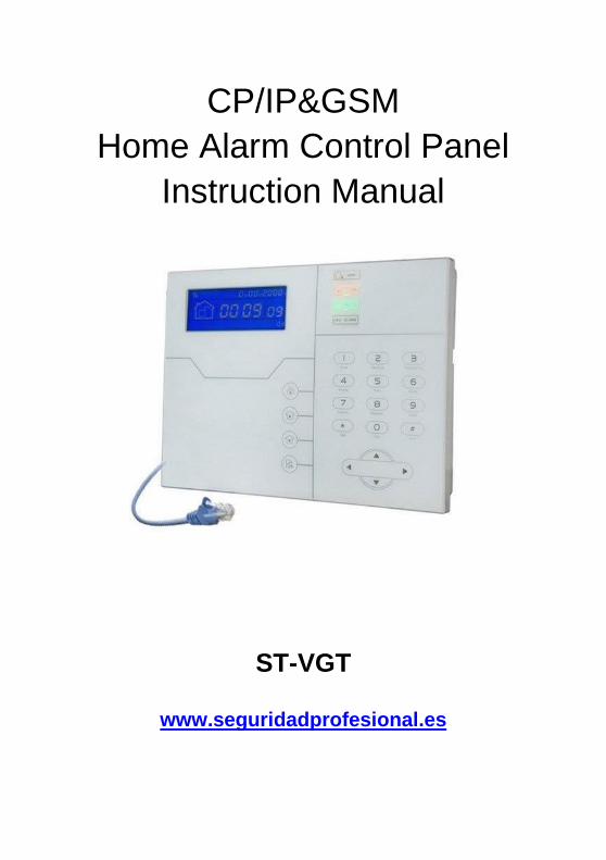
CP/IP&GSM Home Alarm Control Panel
Instruction Manual
ST-VGT
www.seguridadprofesional.es
Brief ........................................................................................................................................ 1
Chapter I Product Introduction ..................................................................................... 2
Chapter II Installation and Connection ................................................................................ 5
2.1 1 Box I nc luded . . . . . . . . . . . . . . . . . . . . . . . . . . . . . . . . . . . . . . . . . . . . . . . . . . . . . . . . . . . . . . . . . . . . . . . . . . . . . . . . 5
2.2 Installation For the Alarm Control Panel ........................................................... 5
2.3 Connection( The wired zones support N.O. N.C detectors) ............................................... 6
2.4 4 Install wired detector ....................................................................... . 6
2.5 Install wireless detector ........................................................................ 7
Chapter III Key description and Basic operation ....................................................... 7
3.1 Key description ......................................................................................... 7
3.2 2 Basic operation ............................ ................................................... .. 9
3.3 LCD Icon ................................................................................................ 10
3.4 System Arm And Disarm Operation ................................................................... 12
3 . 5 A l a r m P r o c e d u r e ................................................................................................... 14
Chapter IV Voice Alarm Receiving And GSM Contr ol ................................................ . 15
4.1 Remote Phone Control .................................................................................................... 15
4.2 Alarm receiving phone operation .................................................................. 15
4.3 GSM remote operation ...................................................................................... 16
4.4 GSM Alarm Receiving ...................................................................................................... 17
4.5 GSM control via SMS .................................................................................................... 17
Chapter V User Settings .......................... .......................................................................... 18
5.1 Set System Clock .......................................................................................................... 18
5.2 Set User Password ....................................................................................................... 18
5.3 Set Voice Phone ........................................................................................................... 18
Chapter VI System Settings ..................... ....................................................................... 19
6.1 Set Password ............................................................................................... 19
6.2 Set Network ................................................................................................. 20
6.3 Set CMS NO ..................................................................................................... 21
6.4 Set Voice Phone ................................................................................................ 23
6.5 Set System Option ................................................................................................. 24
6.5.1 set system clock ............................................................................................ 24
6.5.2 set entry delay .............................................................................................. 24
6.5.3 set exit delay ............................................................................................ 25
6.5.4 set siren time ........................................................................................... 25
6.5.5 set detector loss inspection .................................................................................... 25
6.5.6 set arm/disarm tone ............................................................................................ 26
6.5.7 set arm/disarm report .......................................................................................... 26
6.5.8 set emergency alarm siren type ............................................................................ 27
6.5.9 set others ............................................................................................ 27
6.5.9.1 set force alarm .............................................................................................. 27
6.5.9.2 set AC off inspection time ...................................................................................... 28
6.5.9.3 enable magnetic contact inspection ..................................................................... 28
6.5.9.4 check wireless detector tamper...................................................................... 28
6.5.9.5 set zone alarm times ......................................................................... 29
6.5.9.6 . 6 set l isten-in t ime ......................................................................... 29
6.6 6 Set W i reless Device .................... ................................................. 29
6.6.1 1 set remote controller .................................................................. 30
6.6.1.1 enroll remote controller ..................................................................... 30
6.6.1.2 enter remote control code ..................................................................... 30
6.6.1.3 delete remote controller .................................................................... 31
6 . 6 . 2 se t d e t ect o rs ..................................................................................... 31
6.6.2.1 2. 1 detector coding ..................................................................31
6.6.2.2 enter the detector code .................................................................... 31
6.6.2.3 2. 3 delete detector ...................... ............................................32
6 . 6 . 3 set RFID tags . . . . . . . . . . . . . . . . . . . . . . . . . . . . . . . . . . . . . . . . . . . . . . . . . . . . . . . . . . . . . . . . . . . . . . . . . . . . 32
6.6.3.1 1 RFID tag enrolling ................................................................ 32
6.6.3.2 . 2 RFID tag delete ..................... ............................................. 33
6.6.4 4 set appliance switch ................................................................... 33
6.6.4.1 enroll appliance switch ..................................................................... 33
6.6.4.2 delete appliance switch ..................................................................... 33
6.6.5 5 enroll wireless siren ................................................................... 34
6.6.5.1 enroll wireless siren .......................................................................... 34
6.6.5.2 delete wireless siren .......................................................................... 35
6 . 6 . 6 s e t do o r b e l l ....................................................................................................... 35
6.6.6.1 6. 1 enroll door bell ................................................................... 35
6.6.6.2 . 2 delete door bell ....................................................................... 36
6.7 7 Set Zone ........................................................................................... 36
6.7.1 set zone attribution ........................................................................................ 36
6.7.2 set zone siren type ........................................................................................ 37
6.7.3 set related zone ........................................................................................... 38
6.7.4 set RFID tag function ......................................................................................... 39
6.8 System Maintenance ........................................................................................ 39
6.8.1 set timing arm/disarm .......................................................................................... 39
6.8.2 recording ........................................................................................... 40
6.8.3 play recording........................................................................................... 40
6.8.4 set programmable output port ................................................................................ 40
6.8.5 delete system log .......................................................................................... 41
6.8.6 restore to factory fault ......................................................................................... 41
6.9 Advanced Setting Options .......................................................................................... 42
6.9.1 GSM message language ..................................................................................... 44
6.9.2 boot voice volume ......................................................................................... 44
6.9.3 LCD standby lightness ........................................................................................ 44
6.9.4 CMS Heartbeat Time Settings .............................................................................. 44
6.9.5 GSM SPK ........................................................................................... 45
6.9.6 GSM MIC .............................................................................................. 45
6.9.7 door bell voice options ........................................................................................ 45
6.9.8 web port setting ........................................................................................ 45
6.9.9 alarm network receiving center connection ........................................................ 46
Chapter VII Web IE Introduction .................. ...................................................................... 47
7.1 Remote Control .......................................................................................... 48
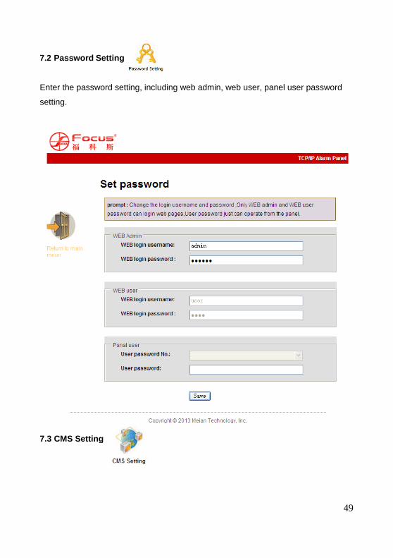
7.2 Password Setting .......................................................................................... 49
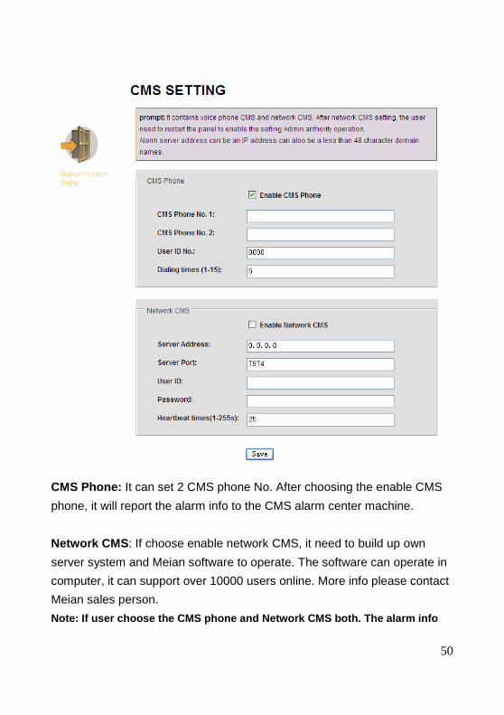
7.3 CMS Setting ............................................................................................ 49
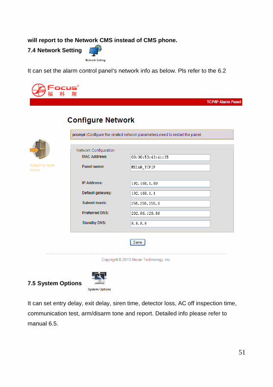
7.4 Network Setting ............................................................................................ 51
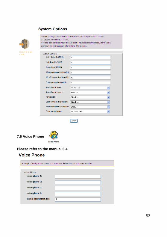
7.5 System Options ............................................................................................ 51
7.6 Voice Phone ............................................................................................ 52
7.7 Wireless Device .......................................................................................... 53
7.8 Zone Setting ........................................................................................... 53
7.9 RFID Setting ........................................................................................... 54
7.10 0 Event Log .............................................................................................. 55
7.11 Remote Upgrade ......................................................................................... 56
7.12 System Reboot ........................................................................................... 58
7.13 Alert Setting .......................................................................................... 58
7.14 Email Setting ......................................................................................... 59
7.15 Time Setting .......................................................................................... 59
7.16 Home Automation ............................................................................................ 60
Chapter VIII Mobile APP Management ................ ............................................................... 61
8.1 enter into the app ............................................................................................. 62
8.1.1 local account ....................................................................................... 62
8.1.2 Platform account ....................................................................................... 64
8.2 zone bypass control ........................................................................................... 65
8.3 3 log events ........................................................................................... 65
8.4 Function settings .......................................................................................... 66
Chapter VXI Technical Specification ............... ................................................................... 68
Chapter VXII Maintenance .......................... ................................................................. 69
10.1 Regular Test ........................................................................................................ 69
10.2 The Cleanliness of Control Main Machine ..................................................................... 69
Chapter VXIII Limitation of the Products .......... .................................................................. 69


1
Brief
Thank you for purchasing the “smart home” products of our company, we hope our
products can bring convenience and and protection for your safety!
The “smart home” system uses the most advanced digital sensing and control
technology, it is a set of smart alarm control system of anti-theft,anti-fire, and
anti-gas leak compatible with wired and wireless alarm. This product is easy to
operate and easy to learn with voice indication all around the operation , complicated
orders are not needed.
The “smart home ”system recommends the most advanced multi-random vault
technology in safety and reliability, which effectively solve the problem of
interference, false positives, false negatives that cannot be solved by similar system
at present .The way the “smart home ” system uses in the alarm signal on the
common high-speed way CONTACT ID makes application of this series of products
wider and compatibility stronger. The system can be widely used in
family ,community,villas,shops,units and so on.
We recommend that you carefully read the instruction to facilitate you for a skilled
operation and use to the product, so the product can better serve you.
We will not notice if there is a change of product performance, if you want to
know the latest features,please contact with the re levant business.
2
Chapter I Product Introduction
1. Alarm mode: with Internet Network and GSM network alarm, GSM network with
GPRS function, remote arm and disarm panel through CMS or SMS. CID protocol,
SMS notification, the priority of Internet Network and GSM Network is Optional.
2. With a new large-screen, full-touch buttons, LCD graphic display steps, work
status, Alarm process easy and intuitive.
3. The full English voice prompting operation: all local or remote operation, alarm
information, event log view.
4. GSM-hook and voice telephone with intercom function.
5. All alarm information can be programmed by 16 ways. Please refer to manual 6.9
6.Sleep mode design,in sleep mode status, all the lights, LCD Back light, voice and
prompt tone are disabled.
7.Alarm panel under idle status is equivalent to a cellphone, you can call through the
GSM network for balance cost inquiries.
8.With associated zones, 8 groups associated zone, 2 kinds of association patterns,
can effectively reduce false alarm or for other functions.
9.PGM output: With a programmed output port, followed by 5 kinds of alarm events
output.
10. The doorbell Audio Optional: 1. Ding Dong 2 Welcome.
11. Remote phone operation:dialing by telephone offsite, after password verification,
you can arm, disarm, listen-in premise, system status query and electrical switches
controls and other operations.
12. Voice Alarm: When panel alarm, it will automatically dial the preset user phone
numbers to report alarm information then you can remote control the panel after
enter user passwords.
13. 32 wireless zones, each wireless zone can automatically learn the codes or be
coded manually via the keyboard and web operation.
14. 8 wired zones, User can set the circuit type and speed of response, support N.O,
N.C.
3
15. Enable enroll total 8 wireless remote, 16 electronic switch, 1 wireless doorbell
and unlimited for quantity of one way wireless siren, 1 wireless two way siren, 16
RFID tags.
16. 6 follow me phone#(voice alarm receiving phone#), 2 for CMS, 4 for private
alarm receiving.
17. Status inspection functions: enable record and inquiry 512 alarm event
messages. Like the time when happens anti-tamper alarm, detector alarm, tel-line
off, arm, disarm, system setting, battery low voltage ect. And also can inquiry the
zone number and alarm type.
18. Timing arm and disarm: 4 sets of timing arm and disarm time.
19. Electrical switches control: User can remote switch on/off via phone or SMS, also
can be controlled manually through the local alarm panel.
20. Zone programmable: factory preset for each zone type. Users can modify all the
zone type according to the actual needs .
21. Clock: Built-in full automatic calendar clock, set to local time consistent.
22. Password access management: the panel has one administrator password 16
user password, The administrator password primarily for system administrators to
set up the alarm system; The user passwords for users in the day-to-day use such
arm/ disarm, remote operation. The administrator password, user password can be
freely modified.
23. For CMS networking alarm, depending on the number of users, the user can set
four user codes(account number).
24. Zone type identification:After an alarm is triggered, the alarm zone number
displayed on the LCD screen of the panel, also can send the detailed report to CMS
which includes alarm locations and zone types.
25. Al-proof function :if try to cut off the wire between wired detector and panel or cut
off the tel line which.
26. The tampering alarm: cut the cable between wired detectors and the panel will
trigger alarm,
27. Anti-tamper function: When someone deliberately dismantled the panel, it will
4
alarm when triggering tamper switch at the back of the panel.
28. CMS communications test: The panel will send a message to CMS at the pre-set
time interval to inspect the communication if normal.
29. Siren options:
Built-in siren, external wired siren, Wireless siren. All sirens can be programmed as
enabled/disable when alarms.
30. The voice speaker volume adjustment: total 8 level,adjust the volume by a panel
arrow keys.
31. Wireless repeater function: can extend the distance between the detector and
the panel by adding a wireless repeater of our company.
32. The wireless detector low battery prompted:
Detectors will send status report to the panel every 1-3 hours, the corresponding
zone number and the battery voltage symbol will be displayed on the LCD screen
and also will report to CMS.
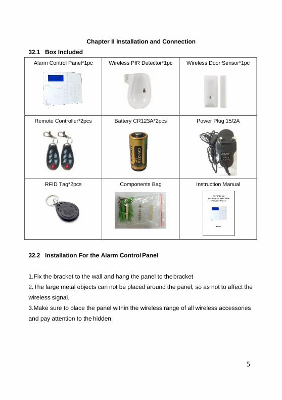
Chapter II Installation and Connection
32.1 Box Included
Alarm Control Panel*1pc
Wireless PIR Detector*1pc
Wireless Door Sensor*1pc
Remote Controller*2pcs
Battery CR123A*2pcs
Power Plug 15/2A
RFID Tag*2pcs
Components Bag
Instruction Manual
32.2 Installation For the Alarm Control Panel
1. Fix the bracket to the wall and hang the panel to the bracket
2. The large metal objects can not be placed around the panel, so as
wireless signal.
3. Make sure to place the panel within the wireless range of all wireless accessories
and pay attention to the hidden.
5
Wireless Door Sensor*1pc
Power Plug 15/2A
Instruction Manual
as not to affect the
range of all wireless accessories
6
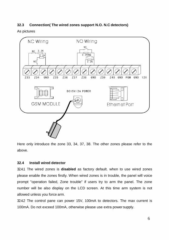
32.3 Connection( The wired zones support N.O. N.C detect ors)
As pictures
Here only introduce the zone 33, 34, 37, 38. The other zones please refer to the
above.
32.4 Install wired detector
32.4.1 The wired zones is disabled as factory default. when to use wired zones
please enable the zones firstly. When wired zones is in trouble, the panel will voice
prompt "operation failed, Zone trouble” if users try to arm the panel. The zone
number will be also display on the LCD screen. At this time arm system is not
allowed unless you force arm.
32.4.2 The control pane can power 15V, 100mA to detectors. The max current is
100mA. Do not exceed 100mA, otherwise please use extra power supply.
7
32.5 Install wireless detector
32.5.1 As the detector ‘s manual says, install coded detector in the area 150m from
the control panel. Please make the walk testing and make sure detector can work
with control panel normally.
32.5.2 Wireless repeater function: (product item No.PB-205R) when wireless detector
is too far from the panel or some wall blocked up between panel and detector which
disable the panel receive the signal from wireless detector. Now you can choose the
repeater to make wireless repeater to achieve wireless signal relay transmitting.
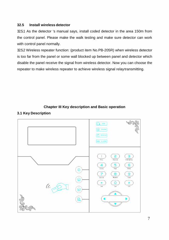
Chapter III Key description and Basic operation
3.1 Key Description
8
Light on under armed status, light flashes under stay status
Light on under disarmed status
Light flashes under AC loss, Zone faulty.
Long light under normal working( without any zone faulty)
Light flashes when alarm
Arm
Home Arm
Disarm
Inquiry
Arrow keys( page down, page up, previous,confirm)
Up and down button can adjust the voice volume
RFID card
Press 3 seconds to trigger fire alarm
Press 3 seconds for medical help
Press 3 seconds for SOS
Press 3 seconds and enter user code to enable or disable delay
zone door bell
Press 3 seconds then enter user code to enable or disable PGM
output
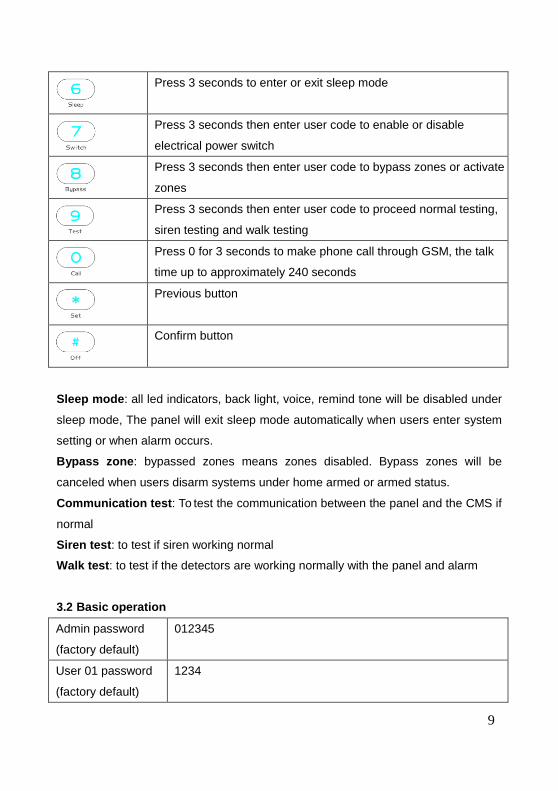
9
Press 3 seconds to enter or exit sleep mode
Press 3 seconds then enter user code to enable or disable
electrical power switch
Press 3 seconds then enter user code to bypass zones or activate
zones
Press 3 seconds then enter user code to proceed normal testing,
siren testing and walk testing
Press 0 for 3 seconds to make phone call through GSM, the talk
time up to approximately 240 seconds
Previous button
Confirm button
Sleep mode : all led indicators, back light, voice, remind tone will be disabled under
sleep mode, The panel will exit sleep mode automatically when users enter system
setting or when alarm occurs.
Bypass zone : bypassed zones means zones disabled. Bypass zones will be
canceled when users disarm systems under home armed or armed status.
Communication test : To test the communication between the panel and the CMS if
normal
Siren test : to test if siren working normal
Walk test : to test if the detectors are working normally with the panel and alarm
3.2 Basic operation
Admin password
(factory default)
012345
User 01 password
(factory default)
1234
10
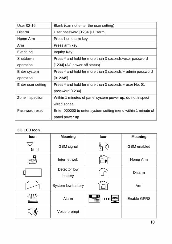
User 02-16 Blank (can not enter the user setting)
Disarm User password [1234 ]+Disarm
Home Arm Press home arm key
Arm Press arm key
Event log Inquiry Key
Shutdown
operation
Press * and hold for more than 3 seconds+user password
[1234] (AC power-off status)
Enter system
operation
Press * and hold for more than 3 seconds + admin password
[012345]
Enter user setting Press * and hold for more than 3 seconds + user No. 01
password [1234]
Zone inspection Within 1 minutes of panel system power up, do not inspect
wired zones.
Password reset Enter 000000 to enter system setting menu within 1 minute of
panel power up
3.3 LCD Icon
Icon Meaning Icon Meaning
GSM signal
GSM enabled
Internet web
Home Arm
Detector low
battery
Disarm
System low battery
Arm
Alarm
Enable GPRS
Voice prompt
11
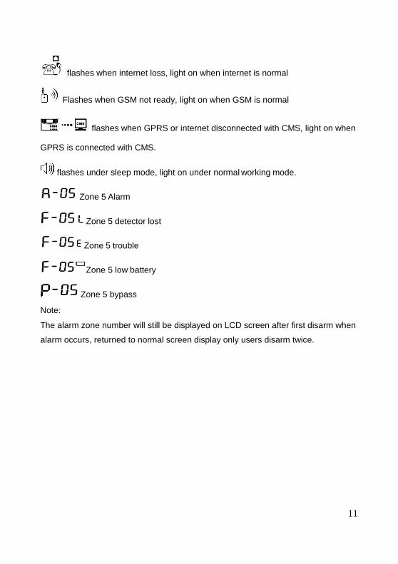
flashes when internet loss, light on when internet is normal
Flashes when GSM not ready, light on when GSM is normal
flashes when GPRS or internet disconnected with CMS, light on when
GPRS is connected with CMS.
flashes under sleep mode, light on under normal working mode.
Zone 5 Alarm
Zone 5 detector lost
Zone 5 trouble
Zone 5 low battery
Zone 5 bypass
Note:
The alarm zone number will still be displayed on LCD screen after first disarm when
alarm occurs, returned to normal screen display only users disarm twice.
12
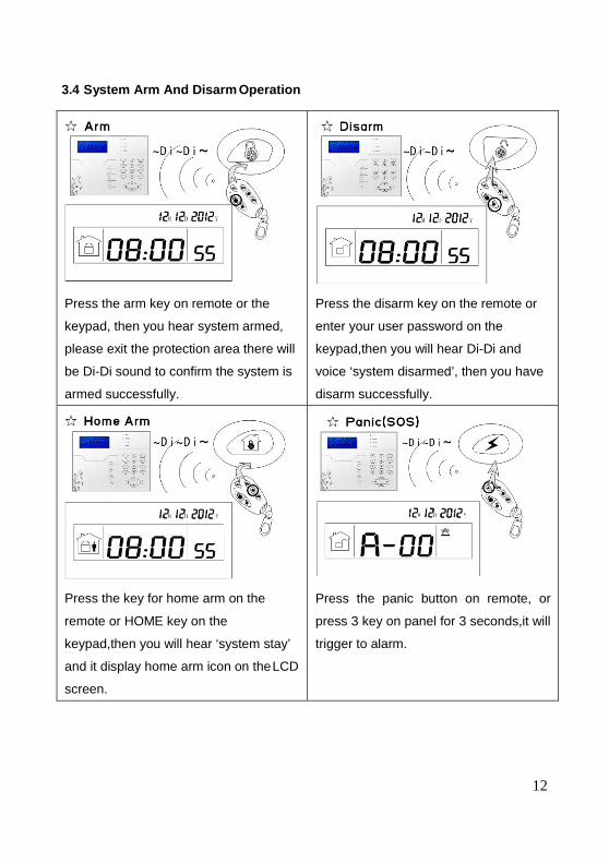
3.4 System Arm And Disarm Operation
Press the arm key on remote or the
keypad, then you hear system armed,
please exit the protection area there will
be Di-Di sound to confirm the system is
armed successfully.
Press the disarm key on the remote or
enter your user password on the
keypad,then you will hear Di-Di and
voice ‘system disarmed’, then you have
disarm successfully.
Press the key for home arm on the
remote or HOME key on the
keypad,then you will hear ‘system stay’
and it display home arm icon on the LCD
screen.
Press the panic button on remote, or
press 3 key on panel for 3 seconds,it will
trigger to alarm.
13
Note:
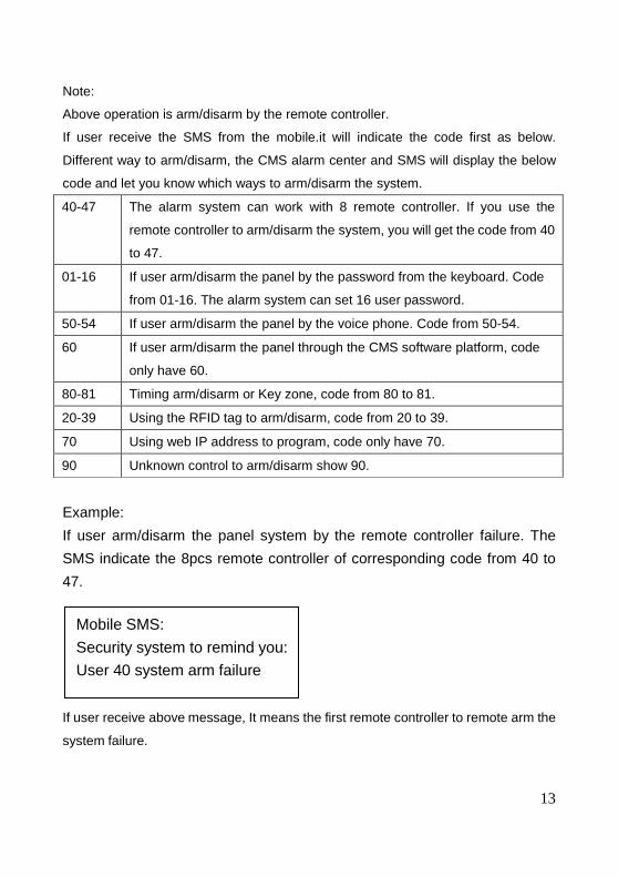
Above operation is arm/disarm by the remote controller.
If user receive the SMS from the mobile.it will indicate the code first as below.
Different way to arm/disarm, the CMS alarm center and SMS will display the below
code and let you know which ways to arm/disarm the system.
Example:
If user arm/disarm the panel system by the remote controller failure. The
SMS indicate the 8pcs remote controller of corresponding code from 40 to
47.
If user receive above message, It means the first remote controller to remote arm the
system failure.
Mobile SMS:
Security system to remind you:
User 40 system arm failure
40-47 The alarm system can work with 8 remote controller. If you use the
remote controller to arm/disarm the system, you will get the code from 40
to 47.
01-16 If user arm/disarm the panel by the password from the keyboard. Code
from 01-16. The alarm system can set 16 user password.
50-54 If user arm/disarm the panel by the voice phone. Code from 50-54.
60 If user arm/disarm the panel through the CMS software platform, code
only have 60.
80-81 Timing arm/disarm or Key zone, code from 80 to 81.
20-39 Using the RFID tag to arm/disarm, code from 20 to 39.
70 Using web IP address to program, code only have 70.
90 Unknown control to arm/disarm show 90.
14
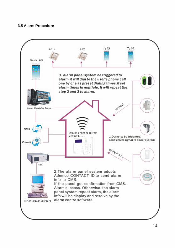
3.5 Alarm Procedure
15
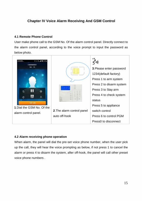
Chapter IV Voice Alarm Receiving And GSM Control
4.1 Remote Phone Control
User make phone call to the GSM No. Of the alarm control panel. Directly connect to
the alarm control panel, according to the voice prompt to input the password as
below photo.
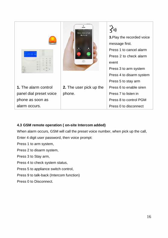
4.2 Alarm receiving phone operation
When alarm, the panel will dial the pre-set voice phone number, when the user pick
up the call, they will hear the voice prompting as below, if not press 1 to cancel the
alarm or press 4 to disarm the system, after off-hook, the panel will call other preset
voice phone numbers .
1.Dial the GSM No. Of the
alarm control panel.
2.The alarm control panel
auto off-hook
3.Please enter password
1234(default factory)
Press 1 to arm system
Press 2 to disarm system
Press 3 to Stay arm
Press 4 to check system
status
Press 5 to appliance
switch control
Press 6 to control PGM
Press0 to disconnect
16
1. The alarm control
panel dial preset voice
phone as soon as
alarm occurs.
2. The user pick up the
phone.
3.Play the recorded voice
message first.
Press 1 to cancel alarm
Press 2 to check alarm
event
Press 3 to arm system
Press 4 to disarm system
Press 5 to stay arm
Press 6 to enable siren
Press 7 to listen in
Press 8 to control PGM
Press 0 to disconnect
4.3 GSM remote operation ( on-site Intercom added)
When alarm occurs, GSM will call the preset voice number, when pick up the call,
Enter 4 digit user password, then voice prompt:
Press 1 to arm system,
Press 2 to disarm system,
Press 3 to Stay arm,
Press 4 to check system status,
Press 5 to appliance switch control,
Press 9 to talk-back (Intercom function)
Press 0 to Disconnect.
17
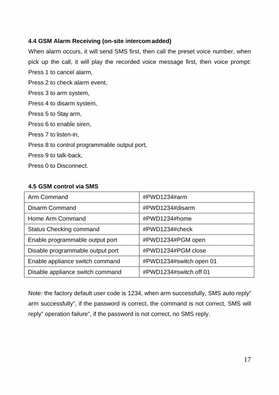
4.4 GSM Alarm Receiving (on-site intercom added)
When alarm occurs, it will send SMS first, then call the preset voice number, when
pick up the call, it will play the recorded voice message first, then voice prompt:
Press 1 to cancel alarm,
Press 2 to check alarm event,
Press 3 to arm system,
Press 4 to disarm system,
Press 5 to Stay arm,
Press 6 to enable siren,
Press 7 to listen-in,
Press 8 to control programmable output port,
Press 9 to talk-back,
Press 0 to Disconnect.
4.5 GSM control via SMS
Arm Command #PWD1234#arm
Disarm Command #PWD1234#disarm
Home Arm Command #PWD1234#home
Status Checking command #PWD1234#check
Enable programmable output port #PWD1234#PGM open
Disable programmable output port #PWD1234#PGM close
Enable appliance switch command #PWD1234#switch open 01
Disable appliance switch command #PWD1234#switch off 01
Note: the factory default user code is 1234, when arm successfully, SMS auto reply”
arm successfully”, if the password is correct, the command is not correct, SMS will
reply” operation failure”, if the password is not correct, no SMS reply.
18
Enter password 2 3 4
Press [*] for 3 seconds
* 1 # 2 #Please enter the serial number of your modified password
1 6 #
Please enter new password,press confirm key to save,press back key to exit.
5
Enter password 2 3 4
2 2 2 2 5 9
Press [*] for 3 seconds
* 1 # 1 #
1 2 1 2
Y M D H MI SNote: According to the flash of Y.M.D.H.Min.Sec. On screen, enter 12.12.22.22.59.36 by return,also can press[up][down] key to move cursor.
Please enter system clock,press confirm key to save,press back key to exit
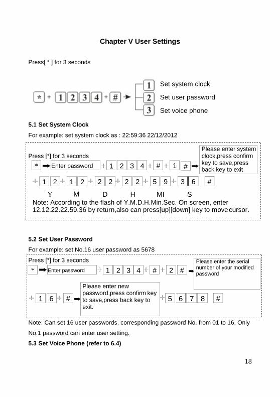
Chapter V User Settings
Press[ * ] for 3 seconds
Set system clock
Set user password
Set voice phone
5.1 Set System Clock
For example: set system clock as : 22:59:36 22/12/2012
3 6 #
5.2 Set User Password
For example: set No.16 user password as 5678
6 7 8 #
Note: Can set 16 user passwords, corresponding password No. from 01 to 16, Only
No.1 password can enter user setting.
5.3 Set Voice Phone (refer to 6.4)
19
1 # Please enter new password,press confirm key to save,press back key to exit
x x x x x #
x x x x #
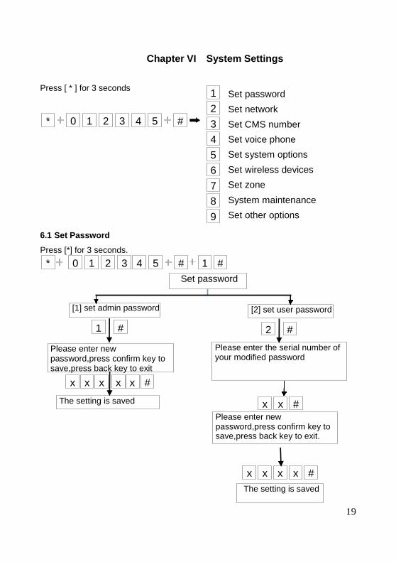
Chapter VI System Settings
Press [ * ] for 3 seconds
6.1 Set Password
Press [*] for 3 seconds.
Set password
Set network
Set CMS number
Set voice phone
Set system options
Set wireless devices
Set zone
System maintenance
Set other options
Please enter new password,press confirm key to save,press back key to exit.
x x # The setting is saved
0 1 2 3 4 5 # 1 #*
Set password
[1] set admin password [2] set user password
Please enter the serial number of your modified password
The setting is saved
* 0 1 2 3 4 5 #
1
2
3
4
5
6
7
8
9
2 #
20
Press [* ] for 3 seconds
* 3 4 5 # 1 # 1 #
8 8 8 8 8 8 #
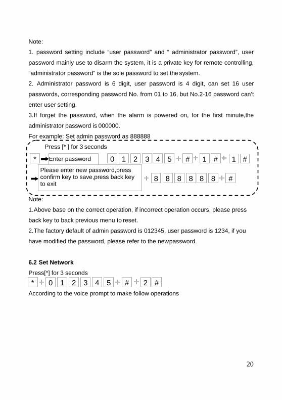
Note:
1. password setting include “user password” and “ administrator password”, user
password mainly use to disarm the system, it is a private key for remote controlling,
“administrator password” is the sole password to set the system.
2. Administrator password is 6 digit, user password is 4 digit, can set 16 user
passwords, corresponding password No. from 01 to 16, but No.2-16 password can’t
enter user setting.
3. If forget the password, when the alarm is powered on, for the first minute,the
administrator password is 000000.
For example: Set admin password as 888888
Enter password 0 1 2 Please enter new password,press confirm key to save,press back key to exit
Note:
1. Above base on the correct operation, if incorrect operation occurs, please press
back key to back previous menu to reset.
2. The factory default of admin password is 012345, user password is 1234, if you
have modified the password, please refer to the new password.
6.2 Set Network
Press[*] for 3 seconds
According to the voice prompt to make follow operations
* 0 1 2 3 4 5 # 2 #
21
1.Set network IP
2.set network gateway
3.set network mask
4.set network CMS IP
# 2 # 3 # 41 # 5 # 6 # 7 #
5.set network CMS port
6.set network CMS account No.
7.set network CMS password
Please enter Please enter Please enter
Please enter 12-digit IP ID,press confirm key to save, press back key to exit.
Please enter 12-digit subnet mask,press confirm key to save,press back key to exit.
5-digit port data,press confirm key to save,press back key to exit.
8-digit CMS account number,pres s confirm key to save,press back key to
8-digit CMS password.pr ess confirm key to save,press back key to exit.
exit.
Note:
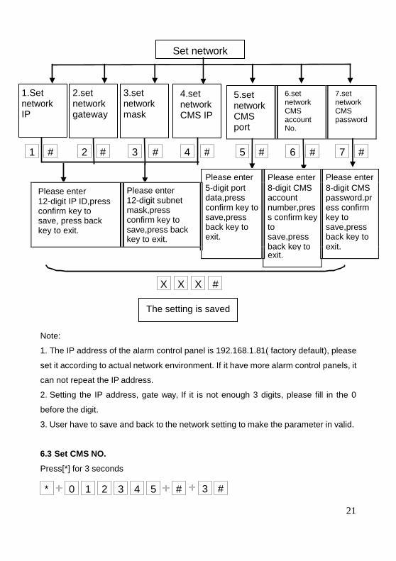
1. The IP address of the alarm control panel is 192.168.1.81( factory default), please
set it according to actual network environment. If it have more alarm control panels, it
can not repeat the IP address.
2. Setting the IP address, gate way, If it is not enough 3 digits, please fill in the 0
before the digit.
3. User have to save and back to the network setting to make the parameter in valid.
6.3 Set CMS NO.
Press[*] for 3 seconds
Set network
X X X #
The setting is saved
* 0 1 2 3 4 5 # 3 #
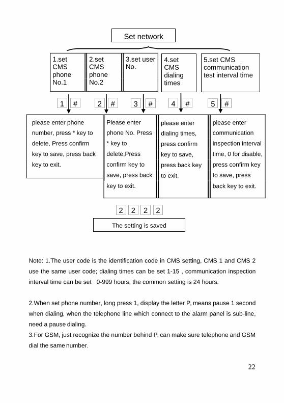
22
please enter phone Please enter please enter please enter
number, press * key to phone No. Press dialing times, communication
delete, Press confirm * key to press confirm inspection interval
key to save, press back delete,Press key to save, time, 0 for disable,
key to exit. confirm key to press back key press confirm key
save, press back to exit. to save, press key to exit. back key to exit.
Note: 1.The user code is the identification code in CMS setting, CMS 1 and CMS 2
use the same user code; dialing times can be set 1-15 , communication inspection
interval time can be set 0-999 hours, the common setting is 24 hours.
2. When set phone number, long press 1, display the letter P, means pause 1 second
when dialing, when the telephone line which connect to the alarm panel is sub-line,
need a pause dialing.
3. For GSM, just recognize the number behind P, can make sure telephone and GSM
dial the same number.
The setting is saved
5 # 4 # 3 # 2 # 1 #
5.set CMS communication test interval time
4.set CMS dialing times
1.set 2.set 3.set user CMS CMS No. phone phone No.1 No.2
Set network
2 2 2 2
23
1 #
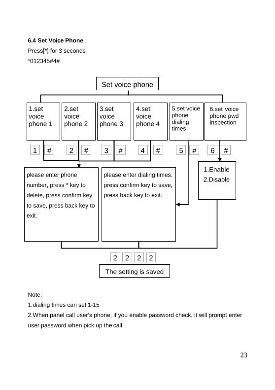
6.4 Set Voice Phone
Press[*] for 3 seconds
*012345#4#
Note:
1. dialing times can set 1-15
2. When panel call user’s phone, if you enable password check, it will prompt enter
user password when pick up the call.
The setting is saved
2 2 2 2
Set voice phone
1.set voice phone 1
2.set voice phone 2
3.set voice phone 3
4.set voice phone 4
5.set voice phone dialing times
6.set voice phone pwd inspection
# 2 # 3 # 4
1.Enable
2.Disable please enter phone
number, press * key to
delete, press confirm key
to save, press back key to
exit.
please enter dialing times.
press confirm key to save,
press back key to exit.
5 # 6 #
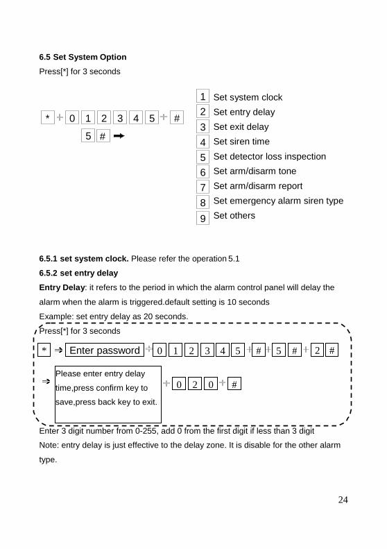
6.5 Set System Option
Press[*] for 3 seconds
Set system clock
Set entry delay
Set exit delay
Set siren time
Set detector loss inspection
Set arm/disarm tone
Set arm/disarm report
Set emergency alarm siren type
Set others
6.5.1 set system clock. Please refer the operation 5.1
6.5.2 set entry delay
Entry Delay : it refers to the period in which the alarm control panel will delay the
alarm when the alarm is triggered.default setting is 10 seconds
Example: set entry delay as 20 seconds.
Enter 3 digit number from 0-255, add 0 from the first digit if less than 3 digit
Note: entry delay is just effective to the delay zone. It is disable for the other alarm
type.
Enter password
Press[*] for 3 seconds * 0 1 2 3 4 5 # 5
0 2 0 #Please enter entry delay
time,press confirm key to
save,press back key to exit.
* 0 1 2 3 4 5 #
1
2
3
4
5
6
7
8
9
5 #
24
Set system clock
Set detector loss inspection
Set arm/disarm tone
rm/disarm report
Set emergency alarm siren type
: it refers to the period in which the alarm control panel will delay the
255, add 0 from the first digit if less than 3 digit
Note: entry delay is just effective to the delay zone. It is disable for the other alarm
2 # 5 #
25
Enter password 4 #
Press [*] for 3 seconds
* 0 1 2 3 4 5 # 5 #
1 0 #Please enter 0 to 30
minutes siren time, press
confirm key to save,press
back key to
6.5.3 set exit delay
Exit Delay: it refers to the period which allows users to exit the zone before arming
is activated after setting arm manually or by remote controller, default setting is 10
seconds.
Example: set exit delay as 20 seconds.
Enter 3 digit number from 0-255, add 0 from the first digit if less than 3 digit
6.5.4 set siren time
The ring times of the siren after the system is triggered. Default setting is 5 minutes.
Example: set siren time is 10 minutes
6.5.5 set detector loss inspection
The alarm control panel in setting the time period of testing whether receive detector
status report or alarm information,generally setting not less than 6 hours, factory
default setting is 0 (Disable)
Enter password 3 #
Press [*] for 3 seconds
* 0 1 2 3 4 5 # 5 #
0 2 0 #Please enter exit delay
time,press confirm key to
save,press back key to exit.
26
Enter password 6 #
Press[*] for 3 seconds.
* 0 1 2 # 5 #
1 #Please choose arm/disarm tone: 1.
siren short sound 2. no voice,press
confirm key to save,press back key
to exit.
Enter password 7 # 0 1 2 # 5 #
Please choose arm/disarm report: 1.
enable 2.disable,press confirm key
to save,press back key to exit.
Example: set the detector loss inspection time is 8 hours.
6.5.6 set arm/disarm tone
When user arm/disarm the alarm control panel by the remote controller whether
enable or disable the built-in siren tone of the alarm control panel. Default setting is
disable.
Example: set arm/disarm tone as siren short sound.
3 4 5
6.5.7 set arm/disarm report
Whether send the arm/disarm report the CMS or not. Default setting is disable
Example: set report the arm/disarm to the CMS.
Press [*] for 3 seconds.
*
1 #
Enter password 5 #
Press [*] for 3 seconds.
* 0 1 2 3 4 5 # 5 #
0 8 #Please enter 0 to 99 hours detector
loss inspection time, 0 for
disable,press confirm key to
save,press back key to exit.
3 4 5
* 0 1 2 3 4 5 #
1
2
3
4
5
6
Enter password
6.5.8 set emergency alarm siren type (Default setting is mute)
Example: set emergency alarm siren type is pedal point
6.5.9 set others
Press[*] for 3 seconds
Set force alarm
Set AC off inspection time
Enable magnetic contact
Check wireless detector
Set zone alarm times
Set listen-in time
6.5.9.1 set force alarm
When sensor faulty has been triggered to alarm frequently, force alarm can bypass
the faulty zone of the sensor. If disable force alarm, the alarm control
arm the system under the faulty status. Default setting is disable.
Press [*] for 3 seconds
* 0 1 2 3 4 5 # 5
1 #
Enter password
Press[*] for 3 seconds * 0 1 2 3 4 5 # 5
1 #Please choose zone siren type:
1.pedal point 2.pulse tone 3.
Mute,press confirm key to
save,press back key to exit.
5 # 9 #
1 # Please choose: 1. Enable force arm
2. Disable force arm, press confirm
key to save,press back key to exit.
27
Set AC off inspection time
contact inspection
Check wireless detector tamper
Set zone alarm times
When sensor faulty has been triggered to alarm frequently, force alarm can bypass
the faulty zone of the sensor. If disable force alarm, the alarm control panel can not
5 #
8 # 5 #
9 #
Enter password 9 #
2 #
Press [*] for 3 seconds
* 0 1 2 3 4 5 # 5 #
0 1 5 #Please enter 0 to 255 minutes AC off
duration time, press confirm key to
save,press back key to exit.
Enter password 9 #
3 #
Press [*] for 3 seconds
* 0 1 2 3 4 5 # 5 #
1 #Please choose: 1. Enable door
contact inspection 2. Disable, press
confirm key to save,press back key
to exit.
Enter password 9 #
4 #
* 0 1 2 3 4 5 # 5 #
2 #
28
Please choose : 1. Enable wireless
detector tamper inspection, 2.
Disable, press confirm key to
save,press back key to exit.
6.5.9.2 set AC off inspection time
When AC loss, delay time of sending the report to the CMS. Default setting is 30
minutes.(0-255 minutes for setting)
*The function mainly used in the power supply unstable area.
6.5.9.3 enable magnetic contact inspection
To detect the door whether open or closed (when separate the magnetic strip from
transmitter, the alarm control panel show zone faulty on the LCD screen and give
report to users. Default setting is disable.
6.5.9.4 check wireless detector tamper
Whether check detector tamper or not, if check, the alarm control panel will alarm, if
do not check the detector tamper, the alarm control panel will not alarm. Default
setting is enable.
29
Enter password 9 #
6 #
* 0 1 2 # 5 #
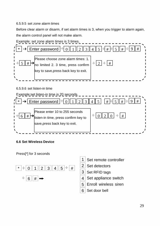
0 2 0 #Please enter 10 to 255 seconds
listen-in time, press confirm key to
save,press back key to exit.
6.5.9.5 set zone alarm times
Before clear alarm or disarm, if set alarm times is 3, when you trigger to alarm again,
the alarm control panel will not make alarm.
Example: set zone alarm times is 3 times.
6.5.9.6 set listen-in time
Example:set listen-in time is 20 seconds.
3 4 5
6.6 Set Wireless Device
Press[*] for 3 seconds
Set remote controller
Set detectors
Set RFID tags
Set appliance switch
Enroll wireless siren
Set door bell
Enter password 9 #
5 #
* 0 1 2 3 4 5 # 5 #
2 #Please choose zone alarm times: 1.
no limited 2. 3 time, press confirm
key to save,press back key to exit.
1
2
3
4
5
6
* 0 1 2 3 4 5 #
6 #
Enter password
1 # 3 #
* 0 1 2 3 4 5 # 6
1 1 2 1 1 3 1 1 4 #
Please enter the serial number of
remote control, press confirm key to
save,press back key to exit.
Please enter
remote controller
No., press confirm
key to save,press
back key to exit.
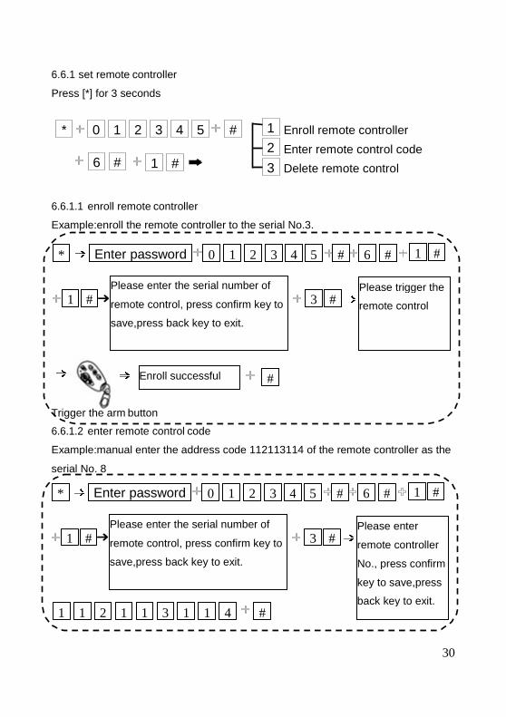
6.6.1 set remote controller
Press [*] for 3 seconds
Enroll remote controller
Enter remote control code
Delete remote control
6.6.1.1 enroll remote controller
Example:enroll the remote controller to the serial No.3.
6.6.1.2 enter remote control code
Example:manual enter the address code 112113114 of the remote controller as the
serial No. 8
Enter password
1 # 3 #
* 0 1 2 3 4 5 # 6
#
Trigger the arm button
Please enter the serial number of
remote control, press confirm key to
save,press back key to exit.
Please trigger the
remote control
Enroll successful
1
2
3
* 0 1 2 3 4 5 #
6 # 1 #
30
1 # 6 #
Please enter
remote controller
No., press confirm
key to save,press
back key to exit.
Enroll remote controller
Enter remote control code
Delete remote control
Example:manual enter the address code 112113114 of the remote controller as the
1 # 6 #
Please trigger the
remote control
Enter password
3 #
* 0 1 2 3 4 5 # 6
5 #Please enter the serial number of
remote control to delete, enter 0 to
delete all, press confirm key to
save,press back key to exit.
6.6.1.3 delete remote controller
Example: delete the serial No. 5 one.
6.6.2 set detectors
Press [*] for 3 seconds
Detector coding
Enter detector code
Delete detector
6.6.2.1 detector coding
Example: set the detector auto enroll to the serial No.9
6.6.2.2 enter the detector code
Example: manual enter the detector address code 011022033 to the serial No.7
detector.
Enter password
1 # 9 #
* 0 1 2 3 4 5 # 6
0
#
Please enter detector No., press
confirm key to save,press back key
to exit.
Enroll successful
1
2
3
* 0 1 2 3 4 5 #
6 # 2 #
31
1 # 6 #
ding
Enter detector code
Example: manual enter the detector address code 011022033 to the serial No.7
2 # 6 #
Please trigger
the detector
Enter password
2 # 7 #
* 0 1 2 3 4 5 # 6
0
0 1 1 0 2 2 0 3 3 #
Please enter detector
code, press confirm k
to save,press back key
to exit.
Please enter detector No.,
press confirm key to
save,press back key to exit.
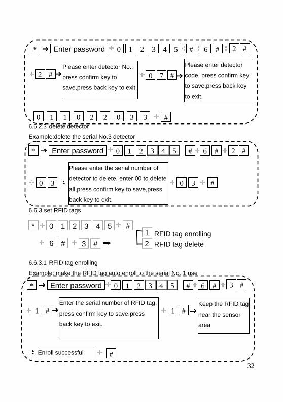
Enter password * 0 1 2 # 6
0 3 0 3
Please enter the serial number of
detector to delete, enter 00 to delete
all,press confirm key to save,press
back key to exit.
Enter password
1 # 1 #
* 0 1 2 # 6
#
Enter the serial number of RFID tag,
press confirm key to save,press
back key to exit.
Keep the RFID tag
near the sensor
area
Enroll successful
6.6.2.3 delete detector
Example:delete the serial No.3 detector
3 4 5
6.6.3 set RFID tags
RFID tag enrolling
RFID tag delete
6.6.3.1 RFID tag enrolling
Example: make the RFID tag auto enroll to the serial No. 1 use
3 4 5
* 0 1 2 3 4 5 # 1
2 6 # 3 #
32
2 # 6 #
Please enter detector
code, press confirm key
to save,press back key
2 # 6 #
#
3 # #
Keep the RFID tag
near the sensor
area
RFID tag enrolling
Enter password
1 # 9 #
* 0 1 2 # 6
0
#
Please enter the serial number of
appliance switch, press confirm key
to save,press back key to exit.
Enroll successful
After enroll RFID tag success. Please set the RFID tag function to make in valid.
Refer to the manual 6.7.4
6.6.3.2 RFID tag delete
Example: delete the serial No. 2 RFID tag.
6.6.4 set appliance switch
Press [*] for 3 seconds
Enroll appliance sw
Delete appliance switch
6.6.4.1 enroll appliance switch
Example: make the appliance switch auto enroll to the serial No. 1.
3 4 5
6.6.4.2 delete appliance switch
Example: delete the serial No.4 appliance switch.
Enter password
2 #
* 0 1 2 3 4 5 # 6
2 #Please enter the serial number of
RFID tags to delete, enter 00 to
delete all, press confirm key to
save,press back key to exit.
* 0 1 2 3 4 5 # 1
2 6 # 4 #
33
4 # 6 #
Please trigger
appliance
switch
nroll RFID tag success. Please set the RFID tag function to make in valid.
Enroll appliance switch
Delete appliance switch
Example: make the appliance switch auto enroll to the serial No. 1.
3 # 6 #
Enter password
Please make wireless siren under
coding status, then press confirm
key to start coding.
This is one way wireless siren,press
confirm key to save,press back key to exit.
1 #
Press [*] for 3 seconds
* 0 1 2 # 6
#
#
Start siren
coding, please
operate as voice
Trigger
the siren
by manual Setting is saved
This is 2-way wireless siren,press confirm
key to save,press back key to exit.
6.6.5 enroll wireless siren
Press [*] for 3 seconds
Enroll wireless siren
Delete wireless siren
6.6.5.1 enroll wireless siren
3 4 5
Note: when the wireless dual way siren be triggered by the tamper button. The LCD
Enter password
2 #
* 0 1 2 3 4 5 # 6
4 #Please enter the serial number of
appliance switch to delete, enter 0 to
delete all, press confirm key to
save,press back key to exit.
* 0 1 2 3 4 5 # 1
2 6 # 5 #
34
5 # 6 #
Start siren
coding, please
operate as voice
Setting is saved
Enroll wireless siren
Delete wireless siren
Note: when the wireless dual way siren be triggered by the tamper button. The LCD
4 # 6 #
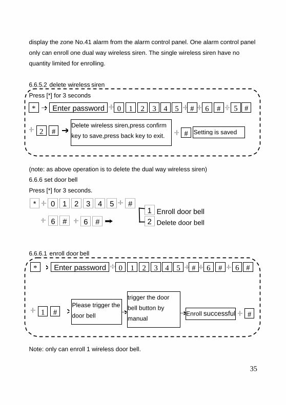
display the zone No.41 alarm from the alarm control panel. One alarm control panel
only can enroll one dual way wireless siren. The single wireless siren have no
quantity limited for enrolling.
6.6.5.2 delete wireless siren
(note: as above operation is to delete the dual way wireless siren)
6.6.6 set door bell
Press [*] for 3 seconds.
Enroll door bell
Delete door bell
6.6.6.1 enroll door bell
Note: only can enroll 1 wireless door bell.
Enter password * 0 1 2 3 4 5 # 6
1 #
trigger the door
bell button by
manual
Please trigger the
door bell Enroll successful
Enter password
Press [*] for 3 seconds
* 0 1 2 3 4 5 # 6
2 # #Delete wireless siren,press confirm
key to save,press back key to exit. Setting is saved
* 0 1 2 3 4 5 # 1
2 6 # 6 #
35
e No.41 alarm from the alarm control panel. One alarm control panel
only can enroll one dual way wireless siren. The single wireless siren have no
6 # 6 #
#successful
5 # 6 #
Setting is saved
36
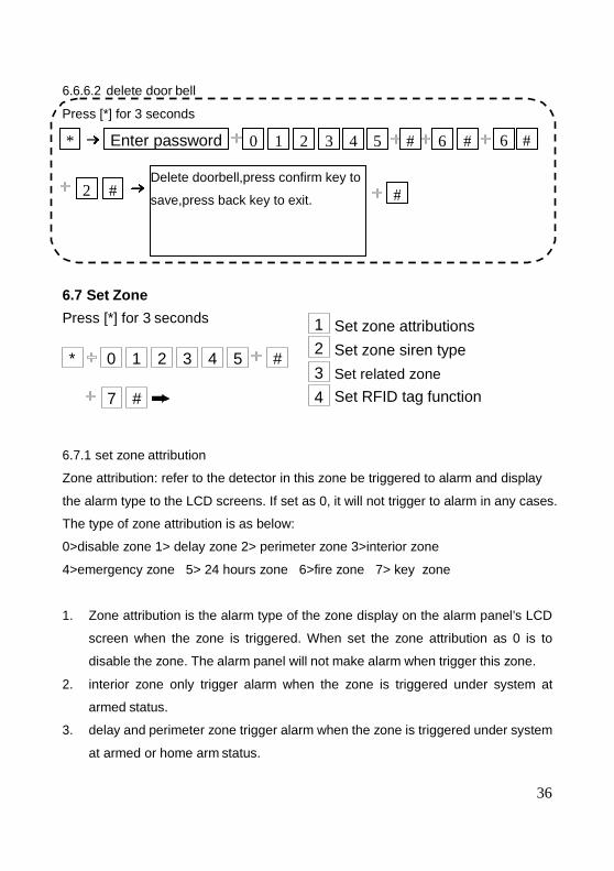
6.6.6.2 delete door bell
6.7 Set Zone
Press [*] for 3 seconds
Set zone attributions
Set zone siren type
Set related zone
Set RFID tag function
6.7.1 set zone attribution
Zone attribution: refer to the detector in this zone be triggered to alarm and display
the alarm type to the LCD screens. If set as 0, it will not trigger to alarm in any cases.
The type of zone attribution is as below:
0>disable zone 1> delay zone 2> perimeter zone 3>interior zone
4>emergency zone 5> 24 hours zone 6>fire zone 7> key zone
1. Zone attribution is the alarm type of the zone display on the alarm panel’s LCD
screen when the zone is triggered. When set the zone attribution as 0 is to
disable the zone. The alarm panel will not make alarm when trigger this zone.
2. interior zone only trigger alarm when the zone is triggered under system at
armed status.
3. delay and perimeter zone trigger alarm when the zone is triggered under system
at armed or home arm status.
Enter password 6 #
Press [*] for 3 seconds
* 0 1 2 3 4 5 # 6 #
2 # #Delete doorbell,press confirm key to
save,press back key to exit.
* 0 1 2 3 4 5 #
1
2
3
4 7 #
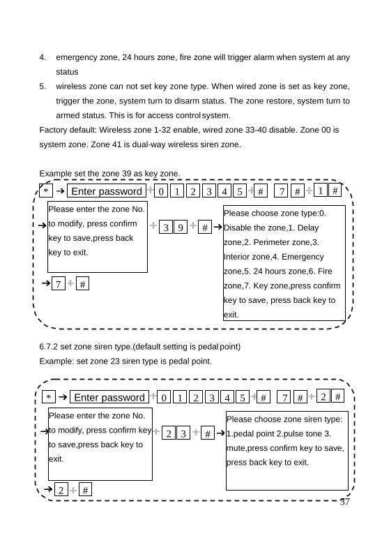
4. emergency zone, 24 hours zone, fire zone will trigger alarm when system at any
status
5. wireless zone can not set key zone type. When wired zone is set as key zone,
trigger the zone, system turn to disarm status. The zone restore, system turn to
armed status. This is for access control system.
Factory default: Wireless zone 1-32 enable, wired zone 33-40 disable. Zone 00 is
system zone. Zone 41 is dual-way wireless siren zone.
Example set the zone 39 as key zone.
6.7.2 set zone siren type.(default setting is pedal point)
Example: set zone 23 siren type is pedal point.
Enter password 1 #
3 9
* 0 1 2 3 4 5 # 7 #
#
7 #
Please enter the zone No.
to modify, press confirm
key to save,press back
key to exit.
Please choose zone type:0.
Disable the zone,1. Delay
zone,2. Perimeter zone,3.
Interior zone,4. Emergency
zone,5. 24 hours zone,6. Fire
zone,7. Key zone,press confirm
key to save, press back key to
exit.
Enter password 2 #
Please enter the zone No.
to modify, press confirm key
to save,press back key to
exit.
2 3
* 0 1 2 3 4 5 # 7 #
#
2 #37
Please choose zone siren type:
1.pedal point 2.pulse tone 3.
mute,press confirm key to save,
press back key to exit.
38
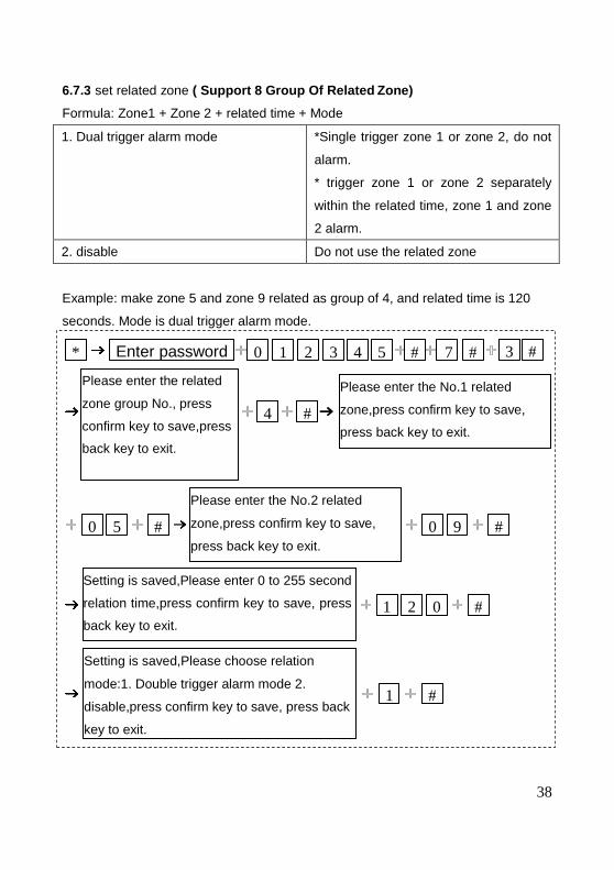
Enter password 3 # * 0 1 2 3 4 5 # 7 #
4 #
0 5 # 0 9 #
1 2 0 #
1 #
Please enter the related
zone group No., press
confirm key to save,press
back key to exit.
Please enter the No.1 related
zone,press confirm key to save,
press back key to exit.
Please enter the No.2 related
zone,press confirm key to save,
press back key to exit.
Setting is saved,Please enter 0 to 255 second
relation time,press confirm key to save, press
back key to exit.
Setting is saved,Please choose relation
mode:1. Double trigger alarm mode 2.
disable,press confirm key to save, press back
key to exit.
6.7.3 set related zone ( Support 8 Group Of Related Zone)
Formula: Zone1 + Zone 2 + related time + Mode
1. Dual trigger alarm mode *Single trigger zone 1 or zone 2, do not
alarm.
* trigger zone 1 or zone 2 separately
within the related time, zone 1 and zone
2 alarm.
2. disable Do not use the related zone
Example: make zone 5 and zone 9 related as group of 4, and related time is 120
seconds. Mode is dual trigger alarm mode.
39
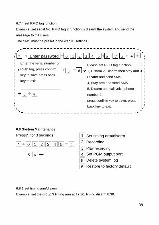
6.7.4 set RFID tag function
Example: set serial No. RFID tag 2 function is disarm the system and send the
message to the users.
The SMS must be preset in the web IE settings.
6.8 System Maintenance
Press[*] for 3 seconds
Set timing arm/disarm
Recording
Play recording
Set PGM output port
Delete system log
Restore to factory default
6.8.1 set timing arm/disarm
Example: set the group 3 timing arm at 17:30, timing disarm 8:30.
Enter password 4 # * 0 1 2 3 4 5 # 7 #
3 #
3 #
Enter the serial number of
RFID tag, press confirm
key to save,press back
key to exit.
Please set RFID tag function
1, Disarm 2, Disarm then stay arm 3
Disarm and send SMS
4, Stay arm and send SMS
5, Disarm and call voice phone
number 1,
press confirm key to save, press
back key to exit.
* 0 1 2 3 4 5 #
1
2
3
4
5
6
8 #
40
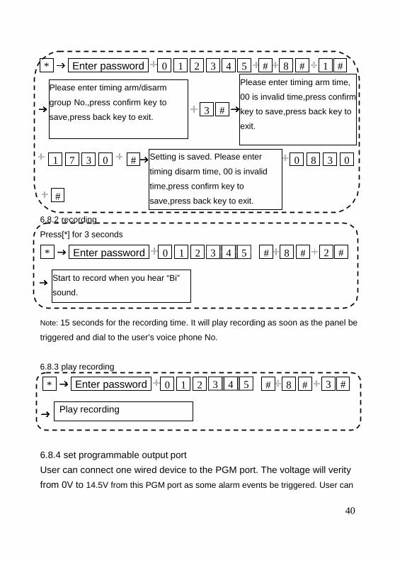
Enter password 2 #
Press[*] for 3 seconds
* 0 1 2 # 8 #
Start to record when you hear “Bi”
sound.
Enter password 3 # * 0 1 2 # 8 #
Play recording
6.8.2 recording
3 4 5
Note: 15 seconds for the recording time. It will play recording as soon as the panel be
triggered and dial to the user’s voice phone No.
6.8.3 play recording
3 4 5
6.8.4 set programmable output port
User can connect one wired device to the PGM port. The voltage will verity
from 0V to 14.5V from this PGM port as some alarm events be triggered. User can
Enter password
Setting is saved. Please enter
timing disarm time, 00 is invalid
time,press confirm key to
save,press back key to exit.
* 0 1 2 3 4 5 # 8 # 1 #
3 #
1 7 3 0 # 0 8 3 0
#
Please enter timing arm time,
00 is invalid time,press confirm
key to save,press back key to
exit.
Please enter timing arm/disarm
group No.,press confirm key to
save,press back key to exit.
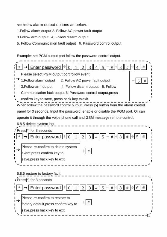
set below alarm output options as below.
1.Follow alarm output 2. Follow AC power fault output
3.Follow arm output 4, Follow disarm output
5, Follow Communication fault output 6. Password control output
Example: set PGM output port follow the password control output.
When follow the password control output. Press [5] button from the alarm control
panel for 3 seconds. Input the password, enable or disable the PGM port. Or can
operate it through the voice phone call and GSM message remote control.
6.8.5 delete system log
6.8.6 restore to factory fault
Enter password 6 #
Press[*] for 3 seconds
* 0 1 2 3 4 5 # 8 #
#
41
Please re-confirm to restore to
factory default,press confirm key to
save,press back key to exit.
Enter password 5 #
Press[*] for 3 seconds
* 0 1 2 3 4 5 # 8 #
#Please re-confirm to delete system
event,press confirm key to
save,press back key to exit.
Enter password 4 #
5 #
* 0 1 2 3 4 5 # 8 #
Please select PGM output port follow event
1.Follow alarm output 2. Follow AC power fault output
3.Follow arm output 4, Follow disarm output 5, Follow
Communication fault output 6. Password control output,press
confirm key to save, press back key to exit.
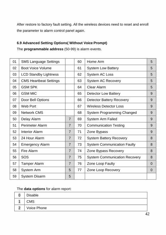
After restore to factory fault setting. All the wireless devices need to reset and enroll
the parameter to alarm control panel again.
6.9 Advanced Setting Options( Without Voice Prompt)
The programmable address (50-99) is alarm events.
01 SMS Language Settings 60 Home Arm 5
02 Boot Voice Volume 61 System Low Battery 5
03 LCD Standby Lightness 62 System AC Loss 5
04 CMS Heartbeat Settings 63 System AC Recovery 5
05 GSM SPK 64 Clear Alarm 5
06 GSM MIC 65 Detector Low Battery 9
07 Door Bell Options 66 Detector Battery Recovery 9
08 Web Port 67 Wireless Detector Loss 9
09 Network CMS 68 System Programming Changed 9
50 Delay Alarm 7 69 System Arm Failed 9
51 Perimeter Alarm 7 70 Communication Testing 9
52 Interior Alarm 7 71 Zone Bypass 9
53 24 Hour Alarm 7 72 System Battery Recovery 8
54 Emergency Alarm 7 73 System Communication Faulty 8
55 Fire Alarm 7 74 Zone Bypass Recovery 8
56 SOS 7 75 System Communication Recovery 8
57 Tamper Alarm 7 76 Zone Loop Faulty 0
58 System Arm 5 77 Zone Loop Recovery 0
59 System Disarm 5
The data options for alarm report:
0 Disable
1 CMS
2 Voice Phone
42
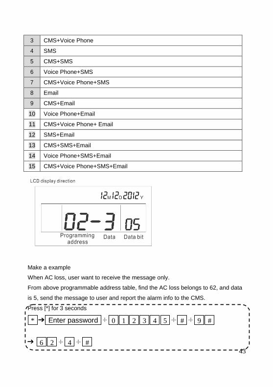
Press [*] for 3 seconds
* 0 1 2 3 4 5 # 9 #
6 2 4 #
Enter password
3 CMS+Voice Phone
4 SMS
5 CMS+SMS
6 Voice Phone+SMS
7 CMS+Voice Phone+SMS
8 Email
9 CMS+Email
10 Voice Phone+Email
11 CMS+Voice Phone+ Email
12 SMS+Email
13 CMS+SMS+Email
14 Voice Phone+SMS+Email
15 CMS+Voice Phone+SMS+Email
Make a example
When AC loss, user want to receive the message only.
From above programmable address table, find the AC loss belongs to 62, and data
is 5, send the message to user and report the alarm info to the CMS.
43
* 0 1 2 3 4 5 # 9 #
0 2 8 #
Enter password
2 5
* 0 1 2 3 4 5 # 9 #
0 4 0 #44
Enter password
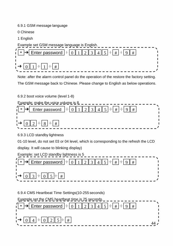
6.9.1 GSM message language
0 Chinese
1 English
Example set GSM message language is English.
Note: after the alarm control panel do the operation of the restore the factory setting.
The GSM message back to Chinese. Please change to English as below operations.
6.9.2 boot voice volume (level 1-8)
Example: make the voice volume is 8.
6.9.3 LCD standby lightness
01-10 level, do not set 03 or 04 level, which is corresponding to the refresh the LCD
display. It will cause to blinking display)
Example: set LCD standby lightness is 5
6.9.4 CMS Heartbeat Time Settings(10-255 seconds)
Example set the CMS heartbeat time is 25 seconds.
* 0 1 2 3 4 5 # 9 #
0 3 0 5 #
Enter password
* 0 1 2 3 4 5 # 9 #
0 1 1 #
Enter password
45
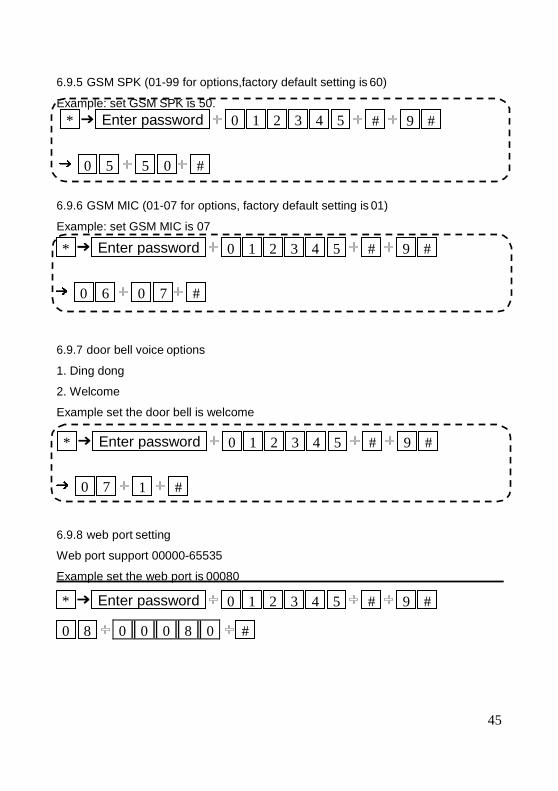
6.9.5 GSM SPK (01-99 for options,factory default setting is 60)
6.9.6 GSM MIC (01-07 for options, factory default setting is 01)
Example: set GSM MIC is 07
6.9.7 door bell voice options
1. Ding dong
2. Welcome
Example set the door bell is welcome
6.9.8 web port setting
Web port support 00000-65535
Example set the web port is 00080
* 0 1 2 3 4 5 # 9 #
0 6 0 7 #
Enter password
0 0 0 8 0
Example: set GSM SPK is 50.
* 0 1 2 3 4 5 # 9 #
0 5 5 0 #
Enter password
0 7
* 0 1 2 3 4 5 # 9 #
1 #
Enter password
* Enter password 0 1 2 3 4 5 # 9 #
0 8 #
46
* 0 1 2 3 4 5 # 9 #
0 9 1 #
Enter password
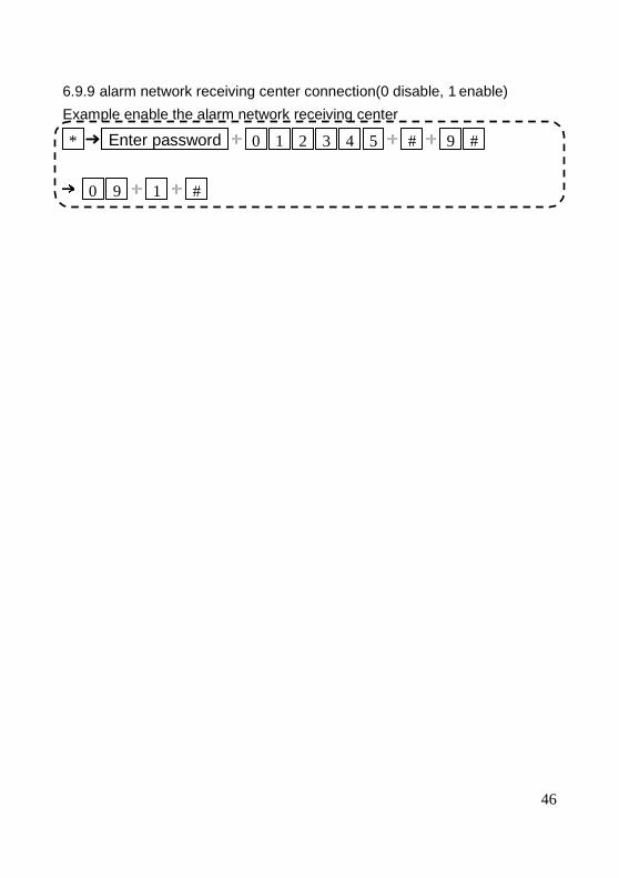
6.9.9 alarm network receiving center connection(0 disable, 1 enable)
Example enable the alarm network receiving center
47
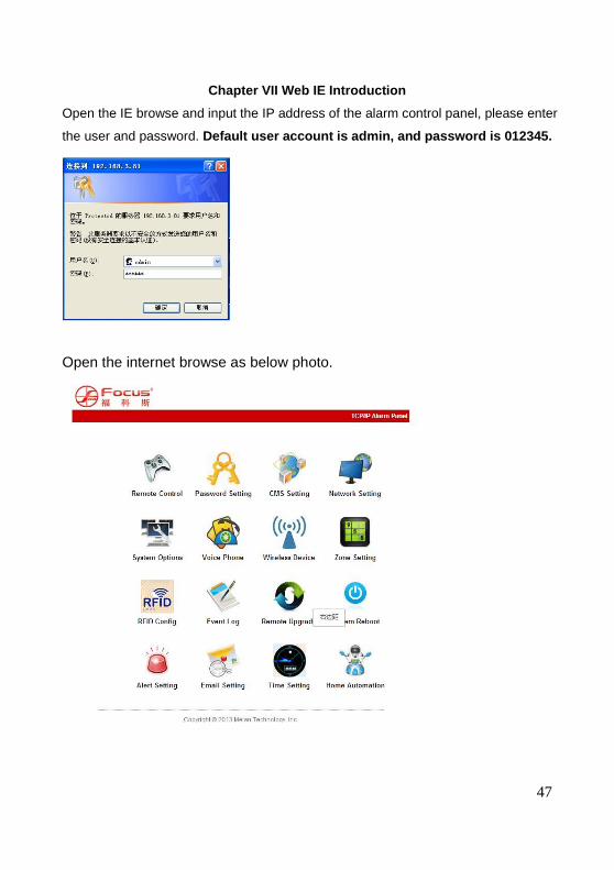
Chapter VII Web IE Introduction
Open the IE browse and input the IP address of the alarm control panel, please enter
the user and password. Default user account is admin, and password is 012345.
Open the internet browse as below photo.
48
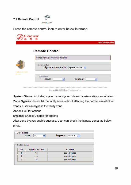
7.1 Remote Control Press the remote control icon to enter below interface.
System Status: including system arm, system disarm, system stay, cancel alarm.
Zone Bypass: do not let the faulty zone without affecting the normal use of other
zones. User can bypass the faulty zone.
Zone: 1-40 for options
Bypass: Enable/Disable for options
After zone bypass enable success. User can check the bypass zones as below
photo.
49
7.2 Password Setting
Enter the password setting, including web admin, web user, panel user password
setting.
7.3 CMS Setting
50
CMS Phone: It can set 2 CMS phone No. After choosing the enable CMS
phone, it will report the alarm info to the CMS alarm center machine.
Network CMS : If choose enable network CMS, it need to build up own
server system and Meian software to operate. The software can operate in
computer, it can support over 10000 users online. More info please contact
Meian sales person.
Note: If user choose the CMS phone and Network CMS both. The alarm info
51
will report to the Network CMS instead of CMS phone .
7.4 Network Setting
It can set the alarm control panel’s network info as below. Pls refer to the 6.2
7.5 System Options
It can set entry delay, exit delay, siren time, detector loss, AC off inspection time,
communication test, arm/disarm tone and report. Detailed info please refer to
manual 6.5.
52
7.6 Voice Phone
Please refer to the manual 6.4.
53
7.7 Wireless Device
It can set remote controller, detector, appliance switch.
It can set up zone attribution and related zone.
Zone attribution configure please refer to manual 6.7
Related Zone please refer to the manual 6.7.1
Note: Key zones only can set from wired zones 33-40.
7.8 Zone Setting
54
7.9 RFID Setting
It can set the RFID’s enroll, delete, and functions from 01-16 tags.
1, Disarm
2, Disarm then stay arm
3 Disarm and send SMS
4, Stay arm and send SMS
5, Disarm and call voice phone number 1
Note: If user choose the RFID tag function as disarm and send SMS.
The user can input the message as RFID SMS text box. It can support 60
characters.
55
7.10 Event Log
It can inquiry the latest 512 event log. If user want to delete the event log, please
enter into the 6.8. 5 delete system log.
56
7.11 Remote Upgrade
Warning: Error of the upgrade file will bring disastrous consequences to
your device, please be careful operation! If there is a upgrade error please
contact us. The upgrade file is devided into application and webpage file. An
upgraded operation need all or part of the files. Please contact your
distributors for further details. If you need to upgrade webpage and
application at the same time, please upgrade the webpage in advance.
Admin Authority Operation
Webpage Ver.: V0.01F
Hardware Ver.: V0.01F Aug 23 2013
Software Ver.: V0.22F Sep 12 2014 10:37:08
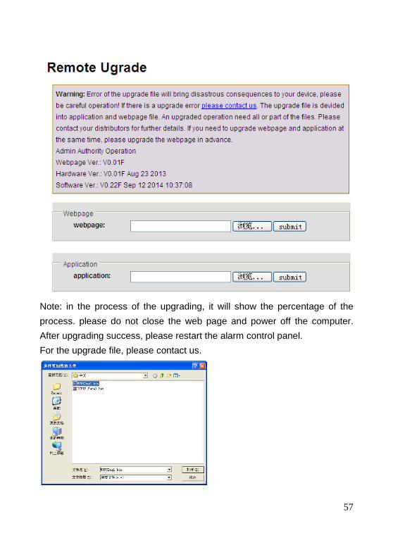
57
Note: in the process of the upgrading, it will show the percentage of the
process. please do not close the web page and power off the computer.
After upgrading success, please restart the alarm control panel.
For the upgrade file, please contact us.
58
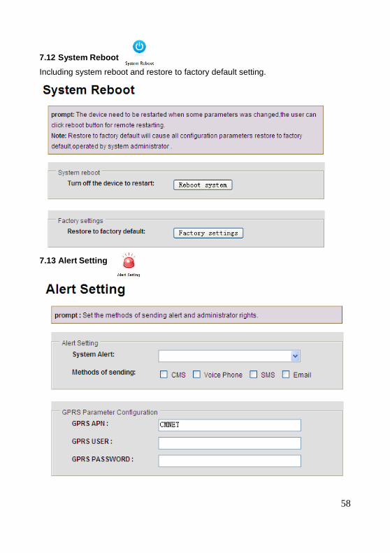
7.12 System Reboot
Including system reboot and restore to factory default setting.
7.13 Alert Setting
59
me: tim
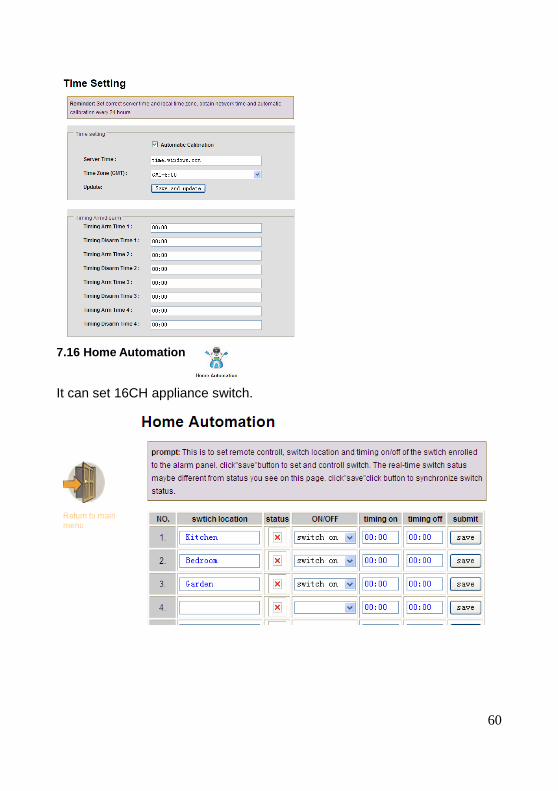
7.15 Time Setting
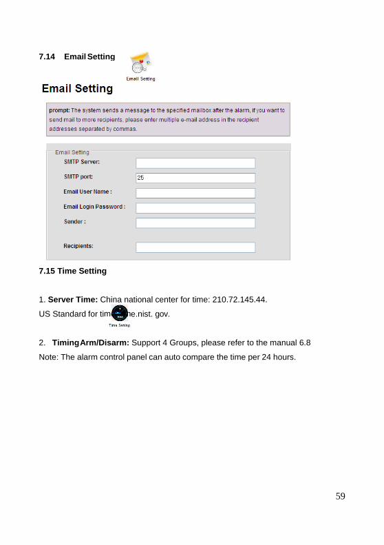
1. Server Time: China national center for time: 210.72.145.44.
US Standard for ti e.nist. gov.
2. Timing Arm/Disarm: Support 4 Groups, please refer to the manual 6.8
Note: The alarm control panel can auto compare the time per 24 hours.
7.14 Email Setting
60
It can set 16CH appliance switch.
7.16 Home Automation
61
Chapter VIII Mobile APP Management
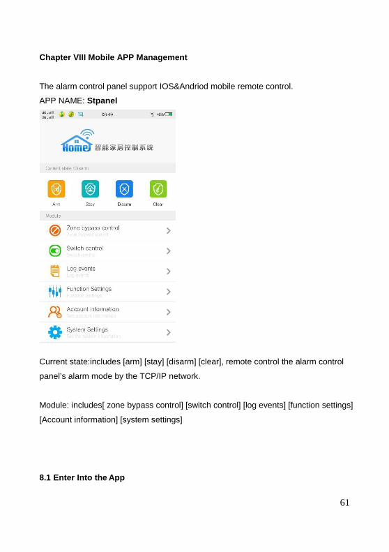
The alarm control panel support IOS&Andriod mobile remote control.
APP NAME: Stpanel
Current state:includes [arm] [stay] [disarm] [clear], remote control the alarm control
panel’s alarm mode by the TCP/IP network.
Module: includes[ zone bypass control] [switch control] [log events] [function settings]
[Account information] [system settings]
8.1 Enter Into the App
62
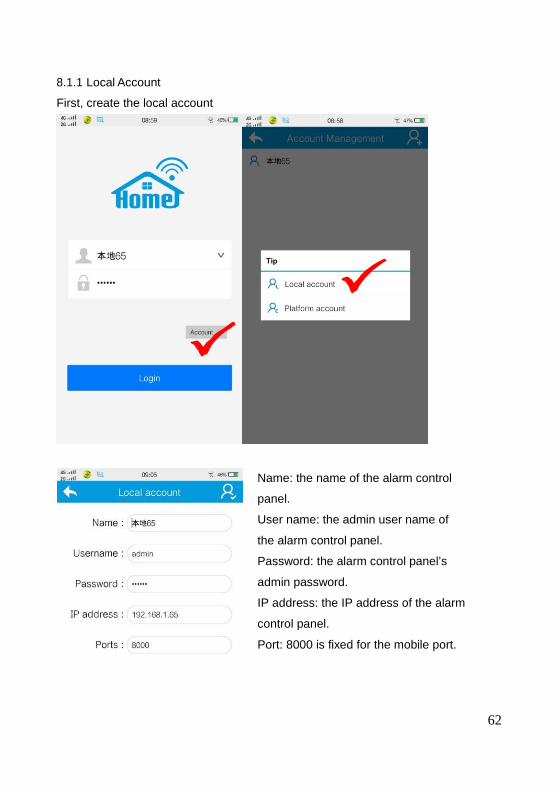
8.1.1 Local Account
First, create the local account
Name: the name of the alarm control
panel.
User name: the admin user name of
the alarm control panel.
Password: the alarm control panel’s
admin password.
IP address: the IP address of the alarm
control panel.
Port: 8000 is fixed for the mobile port.
63
Note:
Before enter into the mobile app. User have to inpu t the IP address and port
configuration.
For the local account, it have two ways to connection.
1. Wan -LAN(mobile is 3G/4G network. Alarm control panel is LAN network)
* If need the WAN access to LAN network. Need to make the port mapping from the
Router.
WEB IE also similar operations
Example:
*IP address for the alarm control panel is 192.168.1.81
*Router port mapping
Mobile WAN PORT 8000 LAN PORT 8000
WEB IE WAN PORT 1027 LAN PORT 1027
* Set network gate way with similar segment to the IP address of the
system.192.168.1.1.
* when you enter into the local account, the IP address should input the dynamic IP
address. Not the alarm control panel IP address.
In china, the dynamic IP address is changing every day. Here suggest customer to
apply for a domain name and binding the dynamic IP address. Directly input the
domain name here can enter into the app.
2. LAN-LAN(mobile and alarm control panel in a one LAN network)
After setting the network IP address, gate, with similar segment and the mobile
cellphone with similar LAN network to the alarm control panel.
Directly input the IP address of the alarm control panel to enter the APP.
64
8.1.2 Platform Account
Need the Meian software to control. Please contact sales person from our Meian
company.
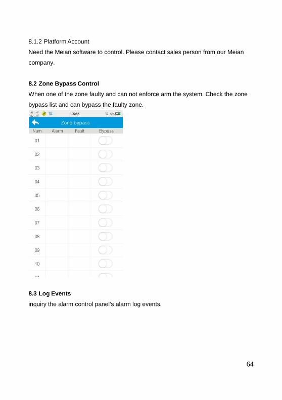
8.2 Zone Bypass Control
When one of the zone faulty and can not enforce arm the system. Check the zone
bypass list and can bypass the faulty zone.
8.3 Log Events
inquiry the alarm control panel’s alarm log events.
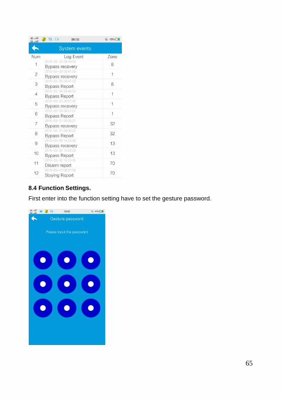
65
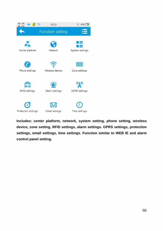
8.4 Function Settings.
First enter into the function setting have to set the gesture password.
66
Includes: center platform, network, system setting, phone setting, wireless
device, zone setting, RFID settings, alarm settings . GPRS settings, protection
settings, email settings, time settings. Function s imilar to WEB IE and alarm
control panel setting.
67
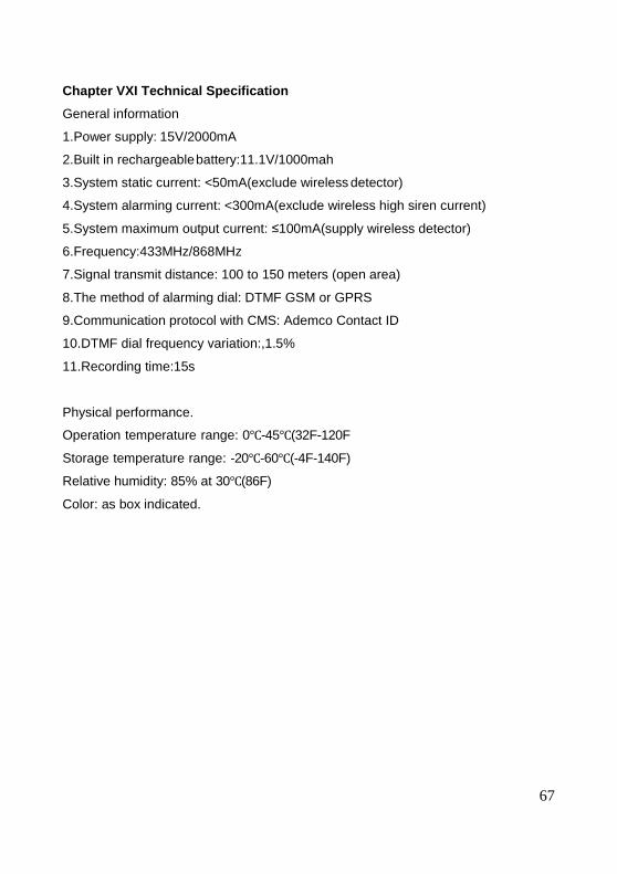
Chapter VXI Technical Specification
General information
1.Power supply: 15V/2000mA
2.Built in rechargeable battery:11.1V/1000mah
3.System static current: <50mA(exclude wireless detector)
4.System alarming current: <300mA(exclude wireless high siren current)
5.System maximum output current: ≤100mA(supply wireless detector)
6.Frequency:433MHz/868MHz
7.Signal transmit distance: 100 to 150 meters (open area)
8.The method of alarming dial: DTMF GSM or GPRS
9.Communication protocol with CMS: Ademco Contact ID
10.DTMF dial frequency variation:,1.5%
11.Recording time:15s
Physical performance.
Operation temperature range: 0℃-45℃(32F-120F
Storage temperature range: -20℃-60℃(-4F-140F)
Relative humidity: 85% at 30℃(86F)
Color: as box indicated.
68
Chapter VXII Maintenance
10.1 Regular Test
Design of components of the system is to reduce maintenance cost, but still it is
suggested that periodical check may be carried out.
10.2 The Cleanliness of Control Main Machine
Main control panel may be stained by fingers or covered by dust after using for a
while. Use soft cotton cloth or sponge to clean it, don't use any lubricant, liquid such
as kerosene, acetone and strong gel which will damage appearance and the
transparency of top window.
Attention: don't use any lubricant, liquid such as kerosene, acetone and strong gel
which will damage appearance and the top transparency of window.
Chapter VXIII Limitation of the Products.
Although the products is a high standard products, there is also some limitation of
them such as false alarm or no alarm. The reasons may be below:
Lack of maintenance, the system needs maintenance and test regularly test the
sensitive of the detector may decrease and the siren may not whistle.
Lack of power supply if no power input and the back up power is not enough, the
panel can not work normally.
Telephone line false, if the telephone line is cut, the panel could not send alarm
signals.
Limitation of smoke detectors, if the smoke is far from the smoke detector, the
detector could not alarm.
If the intrude break in through some door or window not monitored. Or someone
know how to make the system not work.
MEIAN PE
DEMO
SHENZHEN MEIAN TECHNOLOGY CO., LTD http://www.meiantech.com
No.32, Lanshui Rd, Meian Industrial Park, Longgang District, Shenzhen City, China.
postal code: 518116 Phone: +86-755-84844181 Fax: +86-755-84844464