cpm2c operation manual - omron
TRANSCRIPT
Cat. No. W356-E1-08
OPERATION MANUAL
SYSMACCPM2CProgrammable Controller

Notice:OMRON products are manufactured for use according to proper procedures by a qualified operatorand only for the purposes described in this manual.
The following conventions are used to indicate and classify precautions in this manual. Always heedthe information provided with them. Failure to heed precautions can result in injury to people or dam-age to property.
!DANGER Indicates an imminently hazardous situation which, if not avoided, will result in death orserious injury. Additionally, there may be severe property damage.
!WARNING Indicates a potentially hazardous situation which, if not avoided, could result in death orserious injury. Additionally, there may be severe property damage.
!Caution Indicates a potentially hazardous situation which, if not avoided, may result in minor ormoderate injury, or property damage.
OMRON Product ReferencesAll OMRON products are capitalized in this manual. The word “Unit” is also capitalized when it refers toan OMRON product, regardless of whether or not it appears in the proper name of the product.
The abbreviation “Ch,” which appears in some displays and on some OMRON products, often means“word” and is abbreviated “Wd” in documentation in this sense.
The abbreviation “PC” means Programmable Controller and is not used as an abbreviation for anythingelse.
Visual AidsThe following headings appear in the left column of the manual to help you locate different types ofinformation.
Note Indicates information of particular interest for efficient and convenient opera-tion of the product.
1,2,3... 1. Indicates lists of one sort or another, such as procedures, checklists, etc.
OMRON, 1999All rights reserved. No part of this publication may be reproduced, stored in a retrieval system, or transmitted, in any form, orby any means, mechanical, electronic, photocopying, recording, or otherwise, without the prior written permission ofOMRON.
No patent liability is assumed with respect to the use of the information contained herein. Moreover, because OMRON is con-stantly striving to improve its high-quality products, the information contained in this manual is subject to change withoutnotice. Every precaution has been taken in the preparation of this manual. Nevertheless, OMRON assumes no responsibilityfor errors or omissions. Neither is any liability assumed for damages resulting from the use of the information contained inthis publication.
v

TABLE OF CONTENTS
PRECAUTIONS . . . . . . . . . . . . . . . . . . . . . . . . . . . . . . . . . . . xv1 Intended Audience . . . . . . . . . . . . . . . . . . . . . . . . . . . . . . . . . . . . . . . . . . . . . . . . . . . . . . . . xvi
2 General Precautions . . . . . . . . . . . . . . . . . . . . . . . . . . . . . . . . . . . . . . . . . . . . . . . . . . . . . . . xvi
3 Safety Precautions. . . . . . . . . . . . . . . . . . . . . . . . . . . . . . . . . . . . . . . . . . . . . . . . . . . . . . . . . xvi
4 Operating Environment Precautions . . . . . . . . . . . . . . . . . . . . . . . . . . . . . . . . . . . . . . . . . . . xviii
5 Application Precautions . . . . . . . . . . . . . . . . . . . . . . . . . . . . . . . . . . . . . . . . . . . . . . . . . . . . xviii
6 EC Directives . . . . . . . . . . . . . . . . . . . . . . . . . . . . . . . . . . . . . . . . . . . . . . . . . . . . . . . . . . . . xxi
SECTION 1Introduction . . . . . . . . . . . . . . . . . . . . . . . . . . . . . . . . . . . . . . 1
1-1 CPM2C Features and Functions . . . . . . . . . . . . . . . . . . . . . . . . . . . . . . . . . . . . . . . . . . . . . . 2
1-2 System Configurations . . . . . . . . . . . . . . . . . . . . . . . . . . . . . . . . . . . . . . . . . . . . . . . . . . . . . 9
1-3 Structure and Operation . . . . . . . . . . . . . . . . . . . . . . . . . . . . . . . . . . . . . . . . . . . . . . . . . . . . 14
1-4 Functions Listed by Usage . . . . . . . . . . . . . . . . . . . . . . . . . . . . . . . . . . . . . . . . . . . . . . . . . . 22
1-5 Comparison with the CPM1A and CPM2A . . . . . . . . . . . . . . . . . . . . . . . . . . . . . . . . . . . . . 24
1-6 Preparation for Operation . . . . . . . . . . . . . . . . . . . . . . . . . . . . . . . . . . . . . . . . . . . . . . . . . . . 31
1-7 Changes in SW2 . . . . . . . . . . . . . . . . . . . . . . . . . . . . . . . . . . . . . . . . . . . . . . . . . . . . . . . . . . 32
SECTION 2Unit Components and Specifications . . . . . . . . . . . . . . . . . . 35
2-1 Specifications . . . . . . . . . . . . . . . . . . . . . . . . . . . . . . . . . . . . . . . . . . . . . . . . . . . . . . . . . . . . 36
2-2 Unit Components . . . . . . . . . . . . . . . . . . . . . . . . . . . . . . . . . . . . . . . . . . . . . . . . . . . . . . . . . 47
SECTION 3Installation and Wiring . . . . . . . . . . . . . . . . . . . . . . . . . . . . . 83
3-1 Design Precautions . . . . . . . . . . . . . . . . . . . . . . . . . . . . . . . . . . . . . . . . . . . . . . . . . . . . . . . . 84
3-2 Selecting an Installation Site. . . . . . . . . . . . . . . . . . . . . . . . . . . . . . . . . . . . . . . . . . . . . . . . . 85
3-3 Installing the CPM2C . . . . . . . . . . . . . . . . . . . . . . . . . . . . . . . . . . . . . . . . . . . . . . . . . . . . . . 86
3-4 Wiring and Connections . . . . . . . . . . . . . . . . . . . . . . . . . . . . . . . . . . . . . . . . . . . . . . . . . . . . 89
SECTION 4Using a Programming Console . . . . . . . . . . . . . . . . . . . . . . . 151
4-1 Using a Programming Console . . . . . . . . . . . . . . . . . . . . . . . . . . . . . . . . . . . . . . . . . . . . . . . 152
4-2 Programming Console Operations . . . . . . . . . . . . . . . . . . . . . . . . . . . . . . . . . . . . . . . . . . . . 160
4-3 Programming Example . . . . . . . . . . . . . . . . . . . . . . . . . . . . . . . . . . . . . . . . . . . . . . . . . . . . . 185
vii
TABLE OF CONTENTS
SECTION 5Test Runs and Error Processing . . . . . . . . . . . . . . . . . . . . . . 193
5-1 Initial System Checks and Test Run Procedure . . . . . . . . . . . . . . . . . . . . . . . . . . . . . . . . . . 194
5-2 Self-diagnostic Functions . . . . . . . . . . . . . . . . . . . . . . . . . . . . . . . . . . . . . . . . . . . . . . . . . . . 195
5-3 Programming Console Operation Errors. . . . . . . . . . . . . . . . . . . . . . . . . . . . . . . . . . . . . . . . 198
5-4 Programming Errors . . . . . . . . . . . . . . . . . . . . . . . . . . . . . . . . . . . . . . . . . . . . . . . . . . . . . . . 198
5-5 Troubleshooting Flowcharts . . . . . . . . . . . . . . . . . . . . . . . . . . . . . . . . . . . . . . . . . . . . . . . . . 200
5-6 Maintenance Inspections. . . . . . . . . . . . . . . . . . . . . . . . . . . . . . . . . . . . . . . . . . . . . . . . . . . . 208
5-7 Battery Replacement . . . . . . . . . . . . . . . . . . . . . . . . . . . . . . . . . . . . . . . . . . . . . . . . . . . . . . . 209
SECTION 6Expansion Memory Unit . . . . . . . . . . . . . . . . . . . . . . . . . . . . 211
6-1 Overview . . . . . . . . . . . . . . . . . . . . . . . . . . . . . . . . . . . . . . . . . . . . . . . . . . . . . . . . . . . . . . . . 212
6-2 Specifications and Nomenclature . . . . . . . . . . . . . . . . . . . . . . . . . . . . . . . . . . . . . . . . . . . . . 213
6-3 Handling . . . . . . . . . . . . . . . . . . . . . . . . . . . . . . . . . . . . . . . . . . . . . . . . . . . . . . . . . . . . . . . . 214
SECTION 7Simple Communications Unit . . . . . . . . . . . . . . . . . . . . . . . . 221
7-1 Introduction . . . . . . . . . . . . . . . . . . . . . . . . . . . . . . . . . . . . . . . . . . . . . . . . . . . . . . . . . . . . . . 222
7-2 Unit Components and Functions. . . . . . . . . . . . . . . . . . . . . . . . . . . . . . . . . . . . . . . . . . . . . . 228
7-3 Preparation for Operation . . . . . . . . . . . . . . . . . . . . . . . . . . . . . . . . . . . . . . . . . . . . . . . . . . . 233
7-4 Data Memory (DM) Allocation . . . . . . . . . . . . . . . . . . . . . . . . . . . . . . . . . . . . . . . . . . . . . . 237
7-5 DM Settings and Component Communications . . . . . . . . . . . . . . . . . . . . . . . . . . . . . . . . . . 254
7-6 Precautions for Component Communications . . . . . . . . . . . . . . . . . . . . . . . . . . . . . . . . . . . 255
7-7 Error Processing . . . . . . . . . . . . . . . . . . . . . . . . . . . . . . . . . . . . . . . . . . . . . . . . . . . . . . . . . . 256
7-8 Data Refresh Intervals (Reference Data) . . . . . . . . . . . . . . . . . . . . . . . . . . . . . . . . . . . . . . . 258
7-9 Example Application. . . . . . . . . . . . . . . . . . . . . . . . . . . . . . . . . . . . . . . . . . . . . . . . . . . . . . . 258
AppendicesA Standard Models . . . . . . . . . . . . . . . . . . . . . . . . . . . . . . . . . . . . . . . . . . . . . . . . . . . . . . . . . 267
B Dimensions . . . . . . . . . . . . . . . . . . . . . . . . . . . . . . . . . . . . . . . . . . . . . . . . . . . . . . . . . . . . . . 273
C DM Settings Assignment Sheets . . . . . . . . . . . . . . . . . . . . . . . . . . . . . . . . . . . . . . . . . . . . . 281
D SYSMAC and SYSMAC-CPT Support Software . . . . . . . . . . . . . . . . . . . . . . . . . . . . . . . . 289
Index . . . . . . . . . . . . . . . . . . . . . . . . . . . . . . . . . . . . . . . . . . . . 295
Revision History . . . . . . . . . . . . . . . . . . . . . . . . . . . . . . . . . . . 301
viii

About this Manual:
The CPM2C is a compact, high-speed Programmable Controller (PC) designed for control operationsin systems requiring from 10 to 120 I/O points per PC. There are two manuals describing the setup andoperation of the CPM2C: The CPM2C Operation Manual (this manual) and the CPM1/CPM1A/CPM2A/CPM2C/SRM1(-V2) Programming Manual (W353). (The CPM1/CPM1A/CPM2A/CPM2C/SRM1(-V2) Programming Manual is referred to as simply the Programming Manual in this manual.)
This manual describes the system configuration and installation of the CPM2C and provides a basicexplanation of operating procedures for the Programming Consoles.
The Programming Manual (W353) provides detailed descriptions of the CPM2C’s programming func-tions. The CX-Programmer Operation Manual (W437) provides details of operations for the WS02-CXPC1-E CX-Programmer.
Please read this manual carefully and be sure you understand the information provided beforeattempting to install and operate the CPM2C.
Section 1 gives a brief overview of the steps involved in developing of a CPM2C System, describesthe possible system configurations, and describes the CPM2C’s special features and functions.
Section 2 provides the technical specifications of the Units that go together to create a CPM2C PCand describes the main components of the Units.
Section 3 describes how to install and wire a CPM2C PC.
Section 4 describes how to connect the Programming Console, and how to perform the various pro-gramming operations.
Section 5 describes how to perform a test run and how to diagnose and correct the hardware and soft-ware errors that can occur during PC operation.
Section 6 describes how to use the CPM1-EMU01-V1 Expansion Memory Unit.
Section 7 describes the features and functions of the CPM2C-CIF21 Simple Communications Unit,the settings required to use the Unit, and an example application. DM Settings Assignment Sheets areprovided in Appendix C to record data settings.
Appendix A provides tables of CPM2C Units and related products.
Appendix B provides the dimensions of CPM2C Units.
Appendix C provides DM setting assignment sheets for use with the CPM2C-CIF21 Simple Communi-cations Unit.
Appendix D describes SYSMAC and SYSMAC-CPT Support Software capabilities and how to con-nect the CPM2C to the personal computer with this Support Software installed.
!WARNING Failure to read and understand the information provided in this manual may result in per-sonal injury or death, damage to the product, or product failure. Please read each sectionin its entirety and be sure you understand the information provided in the section andrelated sections before attempting any of the procedures or operations given.
ix
Read and Understand this ManualPlease read and understand this manual before using the product. Please consult your OMRON representative if you have any questions or comments.
Warranty and Limitations of Liability
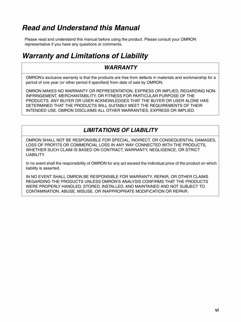
WARRANTY
OMRON's exclusive warranty is that the products are free from defects in materials and workmanship for a period of one year (or other period if specified) from date of sale by OMRON.
OMRON MAKES NO WARRANTY OR REPRESENTATION, EXPRESS OR IMPLIED, REGARDING NON-INFRINGEMENT, MERCHANTABILITY, OR FITNESS FOR PARTICULAR PURPOSE OF THE PRODUCTS. ANY BUYER OR USER ACKNOWLEDGES THAT THE BUYER OR USER ALONE HAS DETERMINED THAT THE PRODUCTS WILL SUITABLY MEET THE REQUIREMENTS OF THEIR INTENDED USE. OMRON DISCLAIMS ALL OTHER WARRANTIES, EXPRESS OR IMPLIED.
LIMITATIONS OF LIABILITY
OMRON SHALL NOT BE RESPONSIBLE FOR SPECIAL, INDIRECT, OR CONSEQUENTIAL DAMAGES, LOSS OF PROFITS OR COMMERCIAL LOSS IN ANY WAY CONNECTED WITH THE PRODUCTS, WHETHER SUCH CLAIM IS BASED ON CONTRACT, WARRANTY, NEGLIGENCE, OR STRICT LIABILITY.
In no event shall the responsibility of OMRON for any act exceed the individual price of the product on which liability is asserted.
IN NO EVENT SHALL OMRON BE RESPONSIBLE FOR WARRANTY, REPAIR, OR OTHER CLAIMS REGARDING THE PRODUCTS UNLESS OMRON'S ANALYSIS CONFIRMS THAT THE PRODUCTS WERE PROPERLY HANDLED, STORED, INSTALLED, AND MAINTAINED AND NOT SUBJECT TO CONTAMINATION, ABUSE, MISUSE, OR INAPPROPRIATE MODIFICATION OR REPAIR.
xi

Application Considerations
SUITABILITY FOR USE
OMRON shall not be responsible for conformity with any standards, codes, or regulations that apply to the combination of products in the customer's application or use of the products.
At the customer's request, OMRON will provide applicable third party certification documents identifying ratings and limitations of use that apply to the products. This information by itself is not sufficient for a complete determination of the suitability of the products in combination with the end product, machine, system, or other application or use.
The following are some examples of applications for which particular attention must be given. This is not intended to be an exhaustive list of all possible uses of the products, nor is it intended to imply that the uses listed may be suitable for the products:
• Outdoor use, uses involving potential chemical contamination or electrical interference, or conditions or uses not described in this manual.
• Nuclear energy control systems, combustion systems, railroad systems, aviation systems, medical equipment, amusement machines, vehicles, safety equipment, and installations subject to separate industry or government regulations.
• Systems, machines, and equipment that could present a risk to life or property.
Please know and observe all prohibitions of use applicable to the products.
NEVER USE THE PRODUCTS FOR AN APPLICATION INVOLVING SERIOUS RISK TO LIFE OR PROPERTY WITHOUT ENSURING THAT THE SYSTEM AS A WHOLE HAS BEEN DESIGNED TO ADDRESS THE RISKS, AND THAT THE OMRON PRODUCTS ARE PROPERLY RATED AND INSTALLED FOR THE INTENDED USE WITHIN THE OVERALL EQUIPMENT OR SYSTEM.
PROGRAMMABLE PRODUCTS
OMRON shall not be responsible for the user's programming of a programmable product, or any consequence thereof.
xii

Disclaimers
CHANGE IN SPECIFICATIONS
Product specifications and accessories may be changed at any time based on improvements and other reasons.
It is our practice to change model numbers when published ratings or features are changed, or when significant construction changes are made. However, some specifications of the products may be changed without any notice. When in doubt, special model numbers may be assigned to fix or establish key specifications for your application on your request. Please consult with your OMRON representative at any time to confirm actual specifications of purchased products.
DIMENSIONS AND WEIGHTS
Dimensions and weights are nominal and are not to be used for manufacturing purposes, even when tolerances are shown.
PERFORMANCE DATA
Performance data given in this manual is provided as a guide for the user in determining suitability and does not constitute a warranty. It may represent the result of OMRON's test conditions, and the users must correlate it to actual application requirements. Actual performance is subject to the OMRON Warranty and Limitations of Liability.
ERRORS AND OMISSIONS
The information in this manual has been carefully checked and is believed to be accurate; however, no responsibility is assumed for clerical, typographical, or proofreading errors, or omissions.
xiii
PRECAUTIONS
This section provides general precautions for using the Programmable Controller (PC) and related devices.
The information contained in this section is important for the safe and reliable application of the ProgrammableController. You must read this section and understand the information contained before attempting to set up oroperate a PC system.
1 Intended Audience . . . . . . . . . . . . . . . . . . . . . . . . . . . . . . . . . . . . . . . . . . . . . xvi
2 General Precautions . . . . . . . . . . . . . . . . . . . . . . . . . . . . . . . . . . . . . . . . . . . . xvi
3 Safety Precautions. . . . . . . . . . . . . . . . . . . . . . . . . . . . . . . . . . . . . . . . . . . . . . xvi
4 Operating Environment Precautions . . . . . . . . . . . . . . . . . . . . . . . . . . . . . . . . xviii
5 Application Precautions . . . . . . . . . . . . . . . . . . . . . . . . . . . . . . . . . . . . . . . . . xviii
6 EC Directives . . . . . . . . . . . . . . . . . . . . . . . . . . . . . . . . . . . . . . . . . . . . . . . . . xxi
xv

Intended Audience 1
1 Intended AudienceThis manual is intended for the following personnel, who must also haveknowledge of electrical systems (an electrical engineer or the equivalent).
• Personnel in charge of installing FA systems.
• Personnel in charge of designing FA systems.
• Personnel in charge of managing FA systems and facilities.
2 General PrecautionsThe user must operate the product according to the performance specifica-tions described in the operation manuals.
Before using the product under conditions which are not described in themanual or applying the product to nuclear control systems, railroad systems,aviation systems, vehicles, combustion systems, medical equipment, amuse-ment machines, safety equipment, and other systems, machines, and equip-ment that may have a serious influence on lives and property if usedimproperly, consult your OMRON representative.
Make sure that the ratings and performance characteristics of the product aresufficient for the systems, machines, and equipment, and be sure to providethe systems, machines, and equipment with double safety mechanisms.
This manual provides information for programming and operating the Unit. Besure to read this manual before attempting to use the Unit and keep this man-ual close at hand for reference during operation.
!WARNING It is extremely important that a PC and all PC Units be used for the specifiedpurpose and under the specified conditions, especially in applications that candirectly or indirectly affect human life. You must consult with your OMRONrepresentative before applying a PC System to the above-mentioned applica-tions.
3 Safety Precautions
!WARNING Connect the ground terminal of the Power Supply Unit (CPM2C-PA201) to aground or 100 Ω or less. Not doing so may result in electric shock.
!WARNING Do not attempt to take any Unit apart while the power is being supplied. Doingso may result in electric shock.
!WARNING Do not touch any of the terminals or terminal blocks while the power is beingsupplied. Doing so may result in electric shock.
!WARNING Do not attempt to disassemble, repair, or modify any Units. Any attempt to doso may result in malfunction, fire, or electric shock.
!WARNING Provide safety measures in external circuits (i.e., not in the ProgrammableController), including the following items, in order to ensure safety in the sys-tem if an abnormality occurs due to malfunction of the PC or another externalfactor affecting the PC operation. Not doing so may result in serious acci-dents.
• Emergency stop circuits, interlock circuits, limit circuits, and similar safetymeasures must be provided in external control circuits.
xvi

Safety Precautions 3
• The PC will turn OFF all outputs when its self-diagnosis function detectsany error or when a severe failure alarm (FALS) instruction is executed.As a countermeasure for such errors, external safety measures must beprovided to ensure safety in the system.
• The PC outputs may remain ON or OFF due to deposition or burning ofthe output relays or destruction of the output transistors. As a counter-measure for such problems, external safety measures must be providedto ensure safety in the system.
• If the 24-VDC output (service power supply) of the Power Supply Unit(CPM2C-PA201) is overloaded or shorted, the voltage may drop causingoutputs to turn OFF. External safety measures must be provided toensure safety in the system in such an event.
!WARNING When handling the Memory Backup Battery, never drop, disassemble, distort,short-circuit, recharge, heat to a temperature exceeding 100°C, or throw intofire. Otherwise the Battery may explode, catch fire, or leak fluid.
!WARNING When transferring programs to other nodes, or when making changes to I/Omemory, confirm the safety of the destination node before transfer. Not doingso may result in injury.
!Caution Execute online edit only after confirming that no adverse effects will becaused by extending the cycle time. Otherwise, the input signals may not bereadable.
!Caution Tighten the screws on the terminal block of the Power Supply Unit (CPM2C-PA201) to a torque of 0.74 to 0.9 N•m. Loose screws may result in burning ormalfunction.
!Caution Do not connect the 24-VDC output (service power supply) or the Power Sup-ply Unit (CPM2C-PA201) to an AC power supply. Connecting it to an ACpower supply will damage the internal circuit.
!Caution When connecting a personal computer or other peripheral device to theCPM2C, either ground the 0 V side of the CPM2C or do not ground at all.Depending on the method of grounding, the 24-V power supply may short-cir-cuit; do not ground the 24-V side as shown in the following diagram.
Example: Connections where 24-V Power Supply Will Short-circuit
CPM2C Peripheral device
24 V
FG FG
0 V 0 V0 V
Non-isolated DC power supply
xvii
Operating Environment Precautions 4
4 Operating Environment Precautions
!Caution Do not operate the control system in the following places:
• Locations subject to direct sunlight.
• Locations subject to temperatures or humidity outside the range specifiedin the specifications.
• Locations subject to condensation as the result of severe changes in tem-perature.
• Locations subject to corrosive or flammable gases.
• Locations subject to dust (especially iron dust) or salts.
• Locations subject to exposure to water, oil, or chemicals.
• Locations subject to shock or vibration.
!Caution Take appropriate and sufficient countermeasures when installing systems inthe following locations:
• Locations subject to static electricity or other forms of noise.
• Locations subject to strong electromagnetic fields.
• Locations subject to possible exposure to radioactivity.
• Locations close to power supplies.
!Caution The operating environment of the PC System can have a large effect on thelongevity and reliability of the system. Improper operating environments canlead to malfunction, failure, and other unforeseeable problems with the PCSystem. Be sure that the operating environment is within the specified condi-tions at installation and remains within the specified conditions during the lifeof the system.
5 Application PrecautionsObserve the following precautions when using the PC System.
!WARNING Always heed these precautions. Failure to abide by the following precautionscould lead to serious or possibly fatal injury.
• Always connect to a ground such that the grounding resistance does notexceed 100 Ω when installing the Units. Not connecting to the correctground may result in electric shock.
• Always turn OFF the power supply to the PC before attempting any of thefollowing. Not turning OFF the power supply may result in malfunction orelectric shock.
• Assembling the Units.
• Connecting or disconnecting the Expansion I/O Units or ExpansionUnits.
• Connecting or wiring the cables.
• Connecting or disconnecting the connectors.
• Setting DIP switches.
• Replacing the battery
xviii
Application Precautions 5
!Caution Failure to abide by the following precautions could lead to faulty operation ofthe PC or the system, or could damage the PC or PC Units. Always heedthese precautions.
• Fail-safe measures must be taken by the customer to ensure safety in theevent of incorrect, missing, or abnormal signals caused by broken signallines, momentary power interruptions, or other causes.
• Use the correct power supply voltage.
• Construct a control circuit so that power supply for the I/O circuits doesnot come ON before power supply for the Unit. If power supply for the I/Ocircuits comes ON before power supply for the Unit, normal operation maybe temporarily interrupted.
• If the operating mode is changed from RUN or MONITOR mode to PRO-GRAM mode, with the IOM Hold Bit ON, the output will hold the mostrecent status. In such a case, ensure that the external load does notexceed specifications. (If operation is stopped because of an operationerror (including FALS instructions), the values in the internal memory ofthe CPU Unit will be saved, but the outputs will all turn OFF.)
• For models with only the super-capacitor installed, the contents of theREAD/WRITE enable area of the DM area, HR area, AR area, and CNTdata area may be damaged if the power is turned OFF for a long time. Toprevent such damage, provide ladder program that will check AR 1314 inorder to ensure proper operation of the system.
• The life expectancy of the output relay varies considerably according to itsswitching capacity and switching conditions. If the output relay is usedbeyond its life expectancy, its contacts may become fused or burned.
• Install the Units properly so that they will not fall off.
• Be sure that all the mounting screws, terminal screws, and cable connec-tor screws are tightened to the torque specified in the relevant manuals.Incorrect tightening torque may result in malfunction.
• Be sure that the terminal blocks and other items with locking devices areproperly locked into place. Improper locking may result in malfunction.
• Be sure that terminal blocks and connectors are connected in the speci-fied direction with the correct polarity. Not doing so may result in malfunc-tion. If the power supply for the I/O circuits is turned ON with the input andoutput connectors reversed, the fuse of output transistor may be blown.
• Use the Unit with the battery housing cover in place to prevent dust or for-eign matter from entering inside the Unit. Not doing so may result in mal-function.
• Install the expansion I/O connector cover to the last Unit (Expansion Unitor Expansion I/O Unit) to prevent dust or foreign matter from enteringinside the Unit. Not doing so may result in malfunction.
• Be sure to attach the labels supplied with the CPM2C or provide otherprotective covers when wiring in order to prevent dust or wiring cuttingsfrom entering the Unit.
• Remove the label after the completion of wiring to ensure proper heat dis-sipation. Leaving the label attached may result in malfunction.
• Use round crimp terminals for wiring the AC power supply input to the ACPower Supply Unit (CPM2C-PA201). For wiring the ground terminals orpower supply service terminals, use crimp terminals or solid wires. Do notconnect bare stranded wires directly to terminals. Connection of barestranded wires may result in burning.
xix

Application Precautions 5
• Be sure to perform wiring in accordance with the CPM2C Operation Man-ual. Incorrect wiring may result in burning.
• Use specified connectors and wiring materials (connector models: C500-CE241/C500-CE242/C500-CE243; terminal block models: AWG28-16with stripped length of 7 mm; Power Supply Unit terminal block: AWG22-14 with stripped length of 7 mm).
• Do not apply voltages to the input terminals in excess of the rated inputvoltage. Excess voltages may result in burning.
• Do not apply voltages or connect loads to the output terminals in excessof the maximum switching capacity. Excess voltage or loads may result inburning.
• Install external breakers and take other safety measures against short-cir-cuiting in external wiring. Insufficient safety measures against short-cir-cuiting may result in burning.
• Always use the power supply voltage specified in the operation manuals.An incorrect voltage may result in malfunction or burning.
• Check the user program for proper execution before actually running it onthe Unit. Not checking the program may result in an unexpected opera-tion.
• Double-check all wiring and switch settings before turning ON the powersupply. Incorrect wiring or switch settings may result in burning.
• Confirm that no adverse effect will occur in the system before attemptingany of the following. Not doing so may result in an unexpected operation.
• Changing the operating mode of the PC.
• Force-setting/force-resetting any bit in memory.
• Changing the present value of any word or any set value in memory.
• Before touching the Unit, be sure to first touch a grounded metallic objectin order to discharge any static built-up. Not doing so may result in mal-function or damage.
• Do not pull on the cables or bend the cables beyond their natural limit.Doing either of these may break the cables.
• Do not apply forces exceeding 50 N to connector sections.
• Do not place objects on top of the cables. Doing so may break the cables.
• Resume operation only after transferring to the new CPU Unit the con-tents of the DM and HR Areas required for resuming operation. Not doingso may result in an unexpected operation.
• Install the Unit properly as specified in the operation manual. Improperinstallation of the Unit may result in malfunction.
• When transporting the Units, use special packing boxes. Be careful not toapply excessive vibration or shock during transportation and not to dropthe product.
• Store the Units within the following temperature and humidity ranges:Storage temperature: –20 to 75°C, storage humidity: 10% to 90% (with noicing or condensation)
• When using a thermocouple-input Temperature Sensor Unit, do not touchthe cold junction compensator. Doing so may result in incorrect tempera-ture measurement.
xx

EC Directives 6
6 EC Directives6-1 Applicable Directives
• EMC Directives
• Low Voltage Directive
6-2 ConceptsEMC DirectivesOMRON devices that comply with EC Directives also conform to the relatedEMC standards so that they can be more easily built into other devices or theoverall machine. The actual products have been checked for conformity toEMC standards (see the following note). Whether the products conform to thestandards in the system used by the customer, however, must be checked bythe customer.
EMC-related performance of the OMRON devices that comply with EC Direc-tives will vary depending on the configuration, wiring, and other conditions ofthe equipment or control panel on which the OMRON devices are installed.The customer must, therefore, perform the final check to confirm that devicesand the overall machine conform to EMC standards.
Note Applicable EMC (Electromagnetic Compatibility) standards are as follows:
EMS (Electromagnetic Susceptibility): EN61131-2EMI (Electromagnetic Interference): EN61000-6-4
(Radiated emission: 10-m regulations)
Low Voltage DirectiveAlways ensure that devices operating at voltages of 50 to 1,000 VAC and 75to 1,500 VDC meet the required safety standards for the PC (EN61131-2).
6-3 Conformance to EC DirectivesThe CPM2C PCs comply with EC Directives. To ensure that the machine ordevice in which the CPM2C PC is used complies with EC Directives, the PCmust be installed as follows:
1,2,3... 1. The CPM2C PC must be installed within a control panel.
2. Reinforced insulation or double insulation must be used for the DC powersupplies used for the communications and I/O power supplies.
3. Basic insulation is provided between the commons of different polarities ofthe output relay for the CPM2C-20@@R (model with 20 relay outputpoints).When connecting devices that operate at voltages higher than 50 VAC andthose that operate on DC power supplies to adjoining relay output termi-nals, use different DC power supplies for output devices from those for in-put devices and the CPM2C power supply.
4. CPM2C PCs complying with EC Directives also conform to the CommonEmission Standard (EN61000-6-4). Radiated emission characteristics (10-m regulations) may vary depending on the configuration of the controlpanel used, other devices connected to the control panel, wiring, and otherconditions. You must therefore confirm that the overall machine or equip-ment complies with EC Directives.
xxi

EC Directives 6
6-4 Relay Output Noise Reduction MethodsThe CPM2C PCs conform to the Common Emission Standards (EN61000-6-4) of the EMC Directives. However, the noise generated when the PC isswitched ON or OFF using the relay output may not satisfy these standards. Insuch a case, a noise filter must be connected to the load side or other appro-priate countermeasures must be provided external to the PC.
Countermeasures taken to satisfy the standards vary depending on thedevices on the load side, wiring, configuration of machines, etc. Following areexamples of countermeasures for reducing the generated noise.
Countermeasures(Refer to EN61000-6-4 for more details.)
Countermeasures are not required if the frequency of load switching for thewhole system with the PC included is less than 5 times per minute.
Countermeasures are required if the frequency of load switching for the wholesystem with the PC included is 5 times or more per minute.
Countermeasure ExamplesWhen switching an inductive load, connect a surge protector, diodes, etc., inparallel with the load or contact as shown below.
Circuit Current Characteristic Required element
AC DC
Yes Yes If the load is a relay or solenoid, there is a time lag between the moment the circuit is opened and the moment the load is reset.If the supply voltage is 24 to 48 V, insert the surge protector in parallel with the load. If the supply voltage is 100 to 200 V, insert the surge protector between the contacts.
The capacitance of the capacitor must be 1 to 0.5 µF per contact current of 1 A and resistance of the resistor must be 0.5 to 1 Ω per contact voltage of 1 V. These values, however, vary with the load and the characteristics of the relay. Decide these values from experi-ments, and take into consideration that the capacitance suppresses spark dis-charge when the contacts are sepa-rated and the resistance limits the current that flows into the load when the circuit is closed again.The dielectric strength of the capacitor must be 200 to 300 V. If the circuit is an AC circuit, use a capacitor with no polarity.
CR method
Power supply
Indu
ctiv
elo
ad
xxii

EC Directives 6
No Yes The diode connected in parallel with the load changes energy accumulated by the coil into a current, which then flows into the coil so that the current will be converted into Joule heat by the resistance of the inductive load.
This time lag, between the moment the circuit is opened and the moment the load is reset, caused by this method is longer than that caused by the CR method.
The reversed dielectric strength value of the diode must be at least 10 times as large as the circuit voltage value. The forward current of the diode must be the same as or larger than the load current.
The reversed dielectric strength value of the diode may be two to three times larger than the supply voltage if the surge protector is applied to electronic circuits with low circuit voltages.
Yes Yes The varistor method prevents the impo-sition of high voltage between the con-tacts by using the constant voltage characteristic of the varistor. There is time lag between the moment the cir-cuit is opened and the moment the load is reset.
If the supply voltage is 24 to 48 V, insert the varistor in parallel with the load. If the supply voltage is 100 to 200 V, insert the varistor between the contacts.
---
Circuit Current Characteristic Required element
AC DC
Diode method
Power supply
Indu
ctiv
elo
ad
Varistor method
Powersupply
Indu
ctiv
elo
ad
xxiii
SECTION 1Introduction
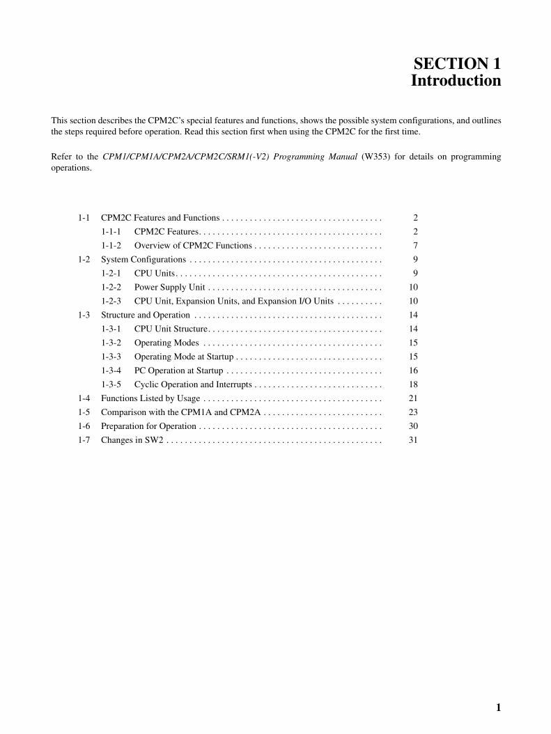
This section describes the CPM2C’s special features and functions, shows the possible system configurations, and outlinesthe steps required before operation. Read this section first when using the CPM2C for the first time.
Refer to the CPM1/CPM1A/CPM2A/CPM2C/SRM1(-V2) Programming Manual (W353) for details on programmingoperations.
1-1 CPM2C Features and Functions . . . . . . . . . . . . . . . . . . . . . . . . . . . . . . . . . . . 2
1-1-1 CPM2C Features. . . . . . . . . . . . . . . . . . . . . . . . . . . . . . . . . . . . . . . . 2
1-1-2 Overview of CPM2C Functions . . . . . . . . . . . . . . . . . . . . . . . . . . . . 7
1-2 System Configurations . . . . . . . . . . . . . . . . . . . . . . . . . . . . . . . . . . . . . . . . . . 9
1-2-1 CPU Units. . . . . . . . . . . . . . . . . . . . . . . . . . . . . . . . . . . . . . . . . . . . . 9
1-2-2 Power Supply Unit . . . . . . . . . . . . . . . . . . . . . . . . . . . . . . . . . . . . . . 10
1-2-3 CPU Unit, Expansion Units, and Expansion I/O Units . . . . . . . . . . 10
1-3 Structure and Operation . . . . . . . . . . . . . . . . . . . . . . . . . . . . . . . . . . . . . . . . . 14
1-3-1 CPU Unit Structure. . . . . . . . . . . . . . . . . . . . . . . . . . . . . . . . . . . . . . 14
1-3-2 Operating Modes . . . . . . . . . . . . . . . . . . . . . . . . . . . . . . . . . . . . . . . 15
1-3-3 Operating Mode at Startup . . . . . . . . . . . . . . . . . . . . . . . . . . . . . . . . 15
1-3-4 PC Operation at Startup . . . . . . . . . . . . . . . . . . . . . . . . . . . . . . . . . . 16
1-3-5 Cyclic Operation and Interrupts . . . . . . . . . . . . . . . . . . . . . . . . . . . . 18
1-4 Functions Listed by Usage . . . . . . . . . . . . . . . . . . . . . . . . . . . . . . . . . . . . . . . 21
1-5 Comparison with the CPM1A and CPM2A . . . . . . . . . . . . . . . . . . . . . . . . . . 23
1-6 Preparation for Operation . . . . . . . . . . . . . . . . . . . . . . . . . . . . . . . . . . . . . . . . 30
1-7 Changes in SW2 . . . . . . . . . . . . . . . . . . . . . . . . . . . . . . . . . . . . . . . . . . . . . . . 31
1

CPM2C Features and Functions Section 1-1
1-1 CPM2C Features and Functions
1-1-1 CPM2C FeaturesThe CPM2C PCs incorporate a variety of features in a compact Unit, includingsynchronized pulse control, interrupt inputs, pulse outputs, and a clock func-tion. The CPM2C CPU Unit is a stand-alone Unit that can handle a broadrange of machine control applications and it is small enough to be incorpo-rated as the control unit in almost any free-standing machine.
The full complement of communications functions provide communicationswith personal computers, other OMRON PCs, and OMRON ProgrammableTerminals. These communications capabilities allow the user to design a low-cost distributed production system.
Basic Functions
CPU Unit Variations The CPM2C PCs are one-piece PCs with 10, 20, or 32 I/O points in I/O termi-nals or a built-in connector. There are 3 types of outputs available (relay out-puts, sinking transistor outputs, and sourcing transistor outputs). All CPM2CPCs require a 24-VDC power supply.
Expansion I/O Units Up to 5 Expansion I/O Units can be connected to the CPU Unit to increase thePC’s I/O capacity to a maximum of 192 I/O points. There are 23 differentExpansion I/O Units available, including Units with 10 I/O points, 24 I/O points,32 I/O points, 8 input points, 8 output points, 16 inputs points, and 16 outputpoints. The maximum I/O capacity of 192 I/O points is achieved by connectingfive 32-point Expansion I/O Units to a CPU Unit with 32 built-in I/O points.
Share Programming Devices
Programming and monitoring for the CPM2C can be performed with CX-Pro-grammer version 2.1 or higher or with a Programming Console. Programmingis also possible with the SYSMAC-CPT or SYSMAC Support Software.
The communications port can be used simulta-neously as two ports: Peripheral and RS-232C.The peripheral port supports Programming Devices, Host Link, and no-protocol communications.The RS-232C port supports Host Link, no-protocol (serial), 1:1 Link, and 1:1 NT Link communications.
CPU Units with 10 I/O points (relay or transistor outputs) or with 20 or 32 I/O points (transistor outputs only) are available. Expansion I/O Units can be connected to increase capacity to 192 I/O points.
2

CPM2C Features and Functions Section 1-1
Built-in Motor Control CapabilitySynchronized Pulse Control (Transistor Outputs Only)
Synchronized pulse control provides an easy way to synchronize the opera-tion of a peripheral piece of equipment with the main equipment. The outputpulse frequency can be controlled as some multiple of the input pulse fre-quency, allowing the speed of a peripheral piece of equipment (such as a sup-ply conveyor) to be synchronized with the speed of the main piece ofequipment.
High-speed Counters and Interrupts
The CPM2C has a two kinds of high-speed counter inputs. The high-speedcounter input has a response frequency of 5 or 20 kHz and the interrupt inputs(in counter mode) have a response frequency of 2 kHz.
The single high-speed counter can be used in any one of the four inputmodes: differential phase mode (5 kHz), pulse plus direction input mode(20 kHz), up/down pulse mode (20 kHz), or increment mode (20 kHz). Inter-rupts can be triggered when the count matches a set value or falls within aspecified range.
The interrupt inputs (counter mode) can be used for incrementing counters ordecrementing counters (2 kHz) and trigger an interrupt (executing the inter-rupt program) when the count matches the target value. Four interrupt inputscan be used in the 20- and 32-point CPU Units and two interrupt inputs can beused in the 10-point CPU Units.
Easy Position Control with Pulse Outputs(Transistor Outputs Only)
CPM2C PCs with transistor outputs have two outputs that can produce 10 Hzto 10 kHz pulses (single-phase outputs).
When used as single-phase pulse outputs, there can be two outputs with afrequency range of 10 Hz to 10 kHz with a fixed duty ratio or 0.1 to 999.9 Hzwith a variable duty ratio (0 to 100% duty ratio).
When used as pulse plus direction or up/down pulse outputs, there can bejust one output with a frequency range of 10 Hz to 10 kHz.
High-speed Input Capabilities for Machine ControlHigh-speed Interrupt Input Function
The 20-point and 32-point CPU Units have 4 inputs that can be used as inter-rupt inputs and the 10-point CPU Units have 2 inputs that can be used asinterrupt inputs. These inputs are shared with quick-response inputs and inter-rupt inputs in counter mode and have a minimum input signal width of 50 µsand response time of 0.3 ms. When an interrupt input goes ON, the main pro-gram is stopped and the interrupt program is executed.
Quick-response Input Function
Regardless of the cycle time, the 20-point and 32-point CPU Units have 4inputs that can be used as quick-response inputs and the 10-point CPU Unitshave 2 inputs that can be used as quick-response inputs. These inputs areshared with interrupt inputs and interrupt inputs in counter mode; they canreliably read input signals with a signal width as short as 50 µs.
Stabilizing Input Filter Function
The input time constant for all inputs can be set to 1 ms, 2 ms, 3 ms, 5 ms,10 ms, 20 ms, 40 ms, or 80 ms. The effects of chattering and external noisecan be reduced by increasing the input time constant.
Encoder
CPM2C
Motor driver Motor
Pulses are output as a fixed multiple of the input frequency.
3

CPM2C Features and Functions Section 1-1
Other Functions
Interval Timer Interrupts The interval timer can be set between 0.5 and 319,968 ms and can be set togenerate just one interrupt (one-shot mode) or periodic interrupts (scheduledinterrupt mode).
Calendar/Clock In CPU Units with a built-in clock, the clock (accuracy within 1 minute/month)can be read from the program to show the current year, month, day, day of theweek, and time. The clock can be set from a Programming Device (such as aProgramming Console) or the time can be adjusted by rounding up or down tothe nearest minute.
Long-term Timer TIML(−−) is a long-term timer that accommodates set values up to 99,990seconds (27 hours, 46 minutes, 30 seconds). When combined with the SEC-ONDS TO HOURS conversion instruction (HMS(−−)), the long-term timer pro-vides an easy way to control equipment scheduling.
Greater Data Handling Capability with Expansion Units
Analog I/O Supported Up to 4 Analog I/O Units can be mounted to the CPM2C. For each Analog I/OUnit mounted to the Unit, 2 analog input points and 1 analog output point areavailable. By mounting 3 (see note) Analog I/O Units, a maximum of 8 analoginput points and 4 analog output points can be made available. (By using acombination of the PID(−−) instruction and PWM(−−) instruction, time propor-tional control is possible.)
• The ranges supported for analog input signals are 0 to 5 V, 0 to 10 V, –10to 10 V, 0 to 20 mA, and 4 to 20 mA, and the resolution is 1/6000 (fullscale). The average processing function and power interruption detectionfunction can be used.
• The ranges supported for analog output signals are 1 to 5 V, 0 to 10 V, –10 to 10 V, 0 to 20 mA, and 4 to 20 mA, and the resolution is 1/6000 (fullscale).
Note When using the CPM2C-PA201, there is a limit to the number of CPM2C-MAD11 Units that can be connected. This limit ensures that the power con-sumption of the CPU Unit, Expansion Units, and Expansion I/O Units does notexceed the total power capacity of the service power supply from the PowerSupply Unit (24 V x 600 mA = 14.4 W).
• CPU Unit with 4-W power consumption: Connect no more than two CPM2C-MAD11 Units
• CPU Unit with 3-W power consumption: Connect no more than three CPM2C-MAD11 Units
Temperature Sensor Units Up to 4 Temperature Sensor Units can be mounted to the CPM2C. There are2 models of Temperature Sensor Unit: One for input from a thermocouple sen-sor and one for input from a platinum resistance thermometer sensor. Thereare 2 input points on each Temperature Sensor Unit.
• Thermocouple inputs (and measurement ranges): K (–200 to 1,300°C,0.0 to 500.0°C), J (–100 to 850°C, 0.0 to 400.0°C).
• Platinum resistance thermometer inputs (and measurement ranges):Pt100 (–200.0 to 650.0°C), JPt100 (–200.0 to 650.0°C).
CompoBus/S I/O Link Units
The CPM2C can be used as a CompoBus/S Slave (with 8 built-in inputs and 8built-in outputs) by connecting a CompoBus/S I/O Link Unit. Up to5 CompoBus/S I/O Link Units can be connected to the CPM2C. In addition tothe conventional “PC + Remote I/O” type of distributed I/O control, “PC + min-iature PC” distributed CPU control is now possible. This means increased
4

CPM2C Features and Functions Section 1-1
modularization, allowing greater standardization of design, improved suitabil-ity to special needs, and easier replacement of malfunctioning Units.
Simple Communications Unit
A Simple Communications Unit can be added to achieve data transfers withgeneral-purpose communications components without preparing communica-tions programs in the PC. Up to 32 communications components can be con-nected, including a combination of communications components supportingthe CompoWay/F protocol along with temperature controllers and DigitalPanel Meters supporting the SYSWAY protocol.
Complete Communications Capabilities
Host Link A Host Link connection can be made through the PC’s communications portused as a RS-232C or peripheral port. A personal computer or ProgrammableTerminal connected in Host Link mode can be used for operations such asreading/writing data in the PC’s I/O memory or reading/changing the PC’soperating mode.
No-protocol Communications
The TXD(48) and RXD(47) instructions can be used in no-protocol mode toexchange data with standard serial devices. For example, data can bereceived from a bar code reader or transmitted to a serial printer. The serialdevices can be connected to the communications port as a RS-232C orperipheral port.
High-speed 1:1 NT Link Communications
In a 1:1 NT Link, an OMRON Programmable Terminal (PT) can be connecteddirectly to the CPM2C. The PT must be connected to the communicationsport as an RS-232C port (not as a peripheral port).
1:1 Host Link Communications
CPM2C
1:N Host Link Communications
B500-AL004Link Adapter
CPM2C
(Up to 32 PCs can be connected.)
NT-AL001
Com
man
ds
Res
pons
es
Com
man
ds
Res
pons
es
Inputting data from a bar code reader
Bar code reader
Outputting data to a serial printer
Serial printer
CPM2C CPM2C
5
CPM2C Features and Functions Section 1-1
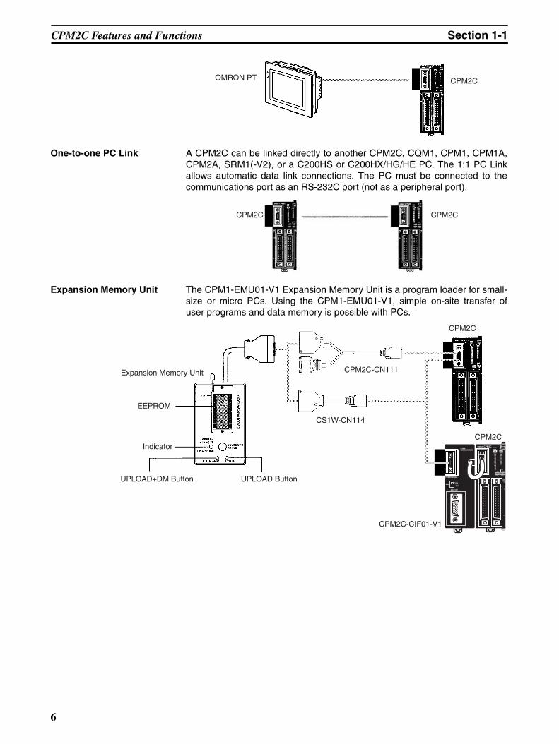
One-to-one PC Link A CPM2C can be linked directly to another CPM2C, CQM1, CPM1, CPM1A,CPM2A, SRM1(-V2), or a C200HS or C200HX/HG/HE PC. The 1:1 PC Linkallows automatic data link connections. The PC must be connected to thecommunications port as an RS-232C port (not as a peripheral port).
Expansion Memory Unit The CPM1-EMU01-V1 Expansion Memory Unit is a program loader for small-size or micro PCs. Using the CPM1-EMU01-V1, simple on-site transfer ofuser programs and data memory is possible with PCs.
OMRON PT CPM2C
CPM2C CPM2C
Expansion Memory Unit
Indicator
UPLOAD+DM Button UPLOAD Button
EEPROM
CPM2C-CN111
CS1W-CN114
CPM2C
CPM2C
CPM2C-CIF01-V1
6
CPM2C Features and Functions Section 1-1
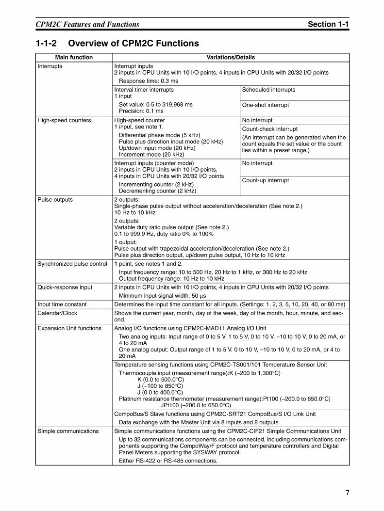
1-1-2 Overview of CPM2C FunctionsMain function Variations/Details
Interrupts Interrupt inputs2 inputs in CPU Units with 10 I/O points, 4 inputs in CPU Units with 20/32 I/O points
Response time: 0.3 ms
Interval timer interrupts1 input
Set value: 0.5 to 319,968 msPrecision: 0.1 ms
Scheduled interrupts
One-shot interrupt
High-speed counters High-speed counter1 input, see note 1.
Differential phase mode (5 kHz)Pulse plus direction input mode (20 kHz)Up/down input mode (20 kHz)Increment mode (20 kHz)
No interrupt
Count-check interrupt
(An interrupt can be generated when the count equals the set value or the count lies within a preset range.)
Interrupt inputs (counter mode)2 inputs in CPU Units with 10 I/O points,4 inputs in CPU Units with 20/32 I/O points
Incrementing counter (2 kHz)Decrementing counter (2 kHz)
No interrupt
Count-up interrupt
Pulse outputs 2 outputs:Single-phase pulse output without acceleration/deceleration (See note 2.)10 Hz to 10 kHz2 outputs:Variable duty ratio pulse output (See note 2.)0.1 to 999.9 Hz, duty ratio 0% to 100%1 output:Pulse output with trapezoidal acceleration/deceleration (See note 2.)Pulse plus direction output, up/down pulse output, 10 Hz to 10 kHz
Synchronized pulse control 1 point, see notes 1 and 2.
Input frequency range: 10 to 500 Hz, 20 Hz to 1 kHz, or 300 Hz to 20 kHzOutput frequency range: 10 Hz to 10 kHz
Quick-response input 2 inputs in CPU Units with 10 I/O points, 4 inputs in CPU Units with 20/32 I/O points
Minimum input signal width: 50 µs
Input time constant Determines the input time constant for all inputs. (Settings: 1, 2, 3, 5, 10, 20, 40, or 80 ms)
Calendar/Clock Shows the current year, month, day of the week, day of the month, hour, minute, and sec-ond.
Expansion Unit functions Analog I/O functions using CPM2C-MAD11 Analog I/O UnitTwo analog inputs: Input range of 0 to 5 V, 1 to 5 V, 0 to 10 V, –10 to 10 V, 0 to 20 mA, or 4 to 20 mAOne analog output: Output range of 1 to 5 V, 0 to 10 V, –10 to 10 V, 0 to 20 mA, or 4 to 20 mA
Temperature sensing functions using CPM2C-TS001/101 Temperature Sensor Unit
Thermocouple input (measurement range):K (–200 to 1,300°C) K (0.0 to 500.0°C)
J (–100 to 850°C)J (0.0 to 400.0°C)
Platinum resistance thermometer (measurement range):Pt100 (–200.0 to 650.0°C)JPt100 (–200.0 to 650.0°C)
CompoBus/S Slave functions using CPM2C-SRT21 CompoBus/S I/O Link UnitData exchange with the Master Unit via 8 inputs and 8 outputs.
Simple communications Simple communications functions using the CPM2C-CIF21 Simple Communications UnitUp to 32 communications components can be connected, including communications com-ponents supporting the CompoWay/F protocol and temperature controllers and Digital Panel Meters supporting the SYSWAY protocol.Either RS-422 or RS-485 connections.
7

CPM2C Features and Functions Section 1-1
Note 1. This input is shared by the high-speed counter and synchronized pulsecontrol functions.
2. This output is shared by the pulse output and synchronized pulse controlfunctions. These functions can be used with transistor outputs only.
8

System Configurations Section 1-2
1-2 System Configurations1-2-1 CPU UnitsCPU Units with 10 I/O Points
Note The function of the SW2 is different from that described in this manual for allUnits marked with an asterisk in the above table with lot numbers of 3180O(August 2000) or earlier. Refer to 1-7 Changes in SW2 for details.
CPU Units with 20 I/O Points
CPU Unit Inputs Outputs Clock Model
10 I/O points (6 inputs, 4 outputs)
I/O terminal block 6 inputs (24 VDC) 4 relay outputs No CPM2C-10CDR-D*
Yes CPM2C-10C1DR-D*
I/O connector
Fujitsu- compatible connector
6 inputs (24 VDC) 4 transistor outputs (sinking)
No CPM2C-10CDTC-D*
Yes CPM2C-10C1DTC-D*
4 transistor outputs (sourcing)
No CPM2C-10CDT1C-D*
Yes CPM2C-10C1DT1C-D*
MIL connector
6 inputs (24 VDC) 4 transistor outputs (sinking)
No CPM2C-10CDTM-D
Yes CPM2C-10C1DTM-D
4 transistor outputs (sourcing)
No CPM2C-10CDT1M-D
Yes CPM2C-10C1DT1M-D
CPU Unit Inputs Outputs Clock Model
20 I/O points (12 inputs, 8 outputs)
I/O terminal block 12 inputs (24 VDC) 8 relay outputs No CPM2C-20CDR-D
Yes CPM2C-20C1DR-D
I/O connector
Fujitsu- compatible connector
12 inputs (24 VDC) 8 transistor outputs (sinking)
No CPM2C-20CDTC-D*
Yes CPM2C-20C1DTC-D*
8 transistor outputs (sourcing)
No CPM2C-20CDT1C-D*
Yes CPM2C-20C1DT1C-D*
MIL connector
12 inputs (24 VDC) 8 transistor outputs (sinking)
No CPM2C-20CDTM-D
Yes CPM2C-20C1DTM-D
8 transistor outputs (sourcing)
No CPM2C-20CDT1M-D
Yes CPM2C-20C1DT1M-D
CPU Unit with Relay Outputs via
Terminal Block
CPU Unit withTransistor Outputs via
Fujitsu-compatible Connector
CPU Unit with Transistor Outputs via MIL Connector
CPU Unit with Relay Outputs via
Terminal Block
CPU Unit with Transistor Outputs via
Fujitsu-compatible Connector
CPU Unit with Transistor Outputs via MIL Connector
9

System Configurations Section 1-2
Note The function of the SW2 is different from that described in this manual for allUnits marked with an asterisk in the above table with lot numbers of 3180O(August 2000) or earlier. Refer to 1-7 Changes in SW2 for details.
CPU Units with 32 I/O Points
1-2-2 Power Supply Unit
1-2-3 CPU Unit, Expansion Units, and Expansion I/O UnitsA series of up to 5 Expansion I/O Units or Expansion Units can be connectedto the expansion I/O connector on the CPU Unit.
CPU Unit with Transistor Outputs via
Fujitsu-compatible Connector
CPU Unit with Transistor Outputs via MIL Connector
CPU Unit Inputs Outputs Clock Model
32 I/O points (16 inputs, 16 outputs)
I/O connector
Fujitsu- compatible connector
16 inputs (24 VDC) 16 transistor out-puts (sinking)
No CPM2C-32CDTC-D
16 transistor out-puts (sourcing)
No CPM2C-32CDT1C-D
MIL connector
16 inputs (24 VDC) 16 transistor out-puts (sinking)
No CPM2C-32CDTM-D
16 transistor out-puts (sourcing)
No CPM2C-32CDT1M-D
AC Power Supply Unit
Name Ratings Model
AC Power Supply Unit 100 to 240 VAC input24 VDC, 600 mA output
CPM2C-PA201
10

System Configurations Section 1-2
There are five types of Units available: Expansion I/O Units, an Analog I/OUnit, Temperature Sensor Units, a CompoBus/S I/O Link Unit, and a SimpleCommunications Unit.
A PC with 192 I/O points (the maximum) can be assembled by connecting fiveExpansion I/O Units to a CPU Unit with 32 I/O points.
Note Be sure that the power supply requirements of the CPU Unit, ExpansionUnits, and Expansion I/O Units do not exceed the available capacity. Onlythree Expansion I/O Units or Expansion Units can be connected when the NT-AL001 Adapter is connected to the communications port (as a RS-232C port).
Expansion I/O Units
Units with Relay Outputs (via Terminal Block)
Expansion I/O Connector(with cover)
Expansion I/O Unit or Expansion Unit
CPU Unit
Expansion I/O Connector(input side)
Expansion I/O Connector(output side, no cover)
CPM2C-32CDTC-D(16 inputs, 16 outputs)
CPM2C-32EDTC(16 inputs, 16 outputs)1 Unit + 5 Units = 96 inputs, 96 outputs
Unit I/O Inputs Outputs Model
10 I/O points 6 inputs (24 VDC) 4 relay outputs CPM2C-10EDR
20 I/O points 12 inputs (24 VDC) 8 relay outputs CPM2C-20EDR
8 output points --- 8 relay outputs CPM2C-8ER
10 I/O Points 8 Output Points20 I/O Points
11

System Configurations Section 1-2
Units with Transistor Outputs via Fujitsu-compatible Connector
Units with Transistor Outputs via MIL Connector
Unit I/O Inputs Outputs Model
24 I/O points 16 inputs (24 VDC) 8 transistor outputs (sinking) CPM2C-24EDTC
8 transistor outputs (sourcing) CPM2C-24EDT1C
32 I/O points 16 inputs (24 VDC) 16 transistor outputs (sinking) CPM2C-32EDTC
16 transistor outputs (sourcing) CPM2C-32EDT1C
8 input points 8 inputs (24 VDC) --- CPM2C-8EDC
16 input points 16 inputs (24 VDC) --- CPM2C-16EDC
8 output points --- 8 transistor outputs (sinking) CPM2C-8ETC
--- 8 transistor outputs (sourcing) CPM2C-8ET1C
16 output points --- 16 transistor outputs (sinking) CPM2C-16ETC
--- 16 transistor outputs (sourcing) CPM2C-16ET1C
8 Output Points 16 Input Points 16 Output Points8 Input Points32 I/O Points24 I/O Points
16 Input or 16 Output Points
8 Input or 8 Output Points32 I/O Points24 I/O Points
Unit I/O Inputs Outputs Model
24 I/O points 16 inputs (24 VDC) 8 transistor outputs (sinking) CPM2C-24EDTM
8 transistor outputs (sourcing) CPM2C-24EDT1M
32 I/O points 16 inputs (24 VDC) 16 transistor outputs (sinking) CPM2C-32EDTM
16 transistor outputs (sourcing) CPM2C-32EDT1M
8 input points 8 inputs (24 VDC) --- CPM2C-8EDM
16 input points 16 inputs (24 VDC) --- CPM2C-16EDM
8 output points --- 8 transistor outputs (sinking) CPM2C-8ETM
--- 8 transistor outputs (sourcing) CPM2C-8ET1M
16 output points --- 16 transistor outputs (sinking) CPM2C-16ETM
--- 16 transistor outputs (sourcing) CPM2C-16ET1M
12

System Configurations Section 1-2
Expansion Units
Note 1. Do not use the CPM2C-CIF21 Simple Communications Unit with an Unitsother than CPM2C Units.
2. The CPM2C-CIF21 Simple Communications Unit is due for release in De-cember 2000.
Adapter Units
Note 1. The CPM2C-CIF01-V1 cannot be used with any PC model other than theCPM2C. A CPM2C-CIF11 or another CPM2C-CIF01-V1 cannot be con-nected onto a CPM2C-CIF01-V1.
Unit Max. number of Units
Inputs Outputs Model
Analog I/O Unit 2 analog inputs1 analog output
4 2 points, 2 words allocated
1 point, 1 word allo-cated
CPM2C-MAD11
Temperature Sen-sor Unit
2 thermocouple inputs
4 2 points, 2 words allocated
--- CPM2C-TS001
2 platinum resis-tance thermometer inputs
2 points, 2 words allocated
--- CPM2C-TS101
CompoBus/S I/O Link Unit
8 input points and 8 output points for the built-in outputs and inputs of the Master Unit
5 8 points, 1 word allocated(Inputs from the Master)
8 points, 1 word allocated(Outputs to the Master)
CPM2C-SRT21
Simple Communications Unit(See notes 1 and 2.)
--- CPM2C-CIF21
CPM2C-MAD11Analog I/O Unit
CPM2C-TS001Temperature Sensor Unit
CPM2C-SRT21CompoBus/S I/O Link Unit
CPM2C-CIF21Simple Communications Unit
Peripheral/RS-232C Adapter Unit RS-422/232C Adapter Unit
Unit Conversion Model
Peripheral/RS-232C Adapter Unit CPU Unit’s communications port → Peripheral port + RS-232C port
CPM2C-CIF01-V1
RS-422/RS-232C Adapter Unit CPU Unit’s communications port → RS422 port + RS-232C port
CPM2C-CIF11
13

Structure and Operation Section 1-3
2. Although a CPM2C-CN111 can be connected to a CPM2C-CIF01-V1, it isnot possible to use the peripheral port and the RS-232C port on theCPM2C-CN111 simultaneously. If an attempt is made to use both ports si-multaneously, communications will not be performed properly and incor-rect operation may result.
1-3 Structure and Operation
1-3-1 CPU Unit StructureThe following diagram shows the internal structure of the CPU Unit.
I/O Memory The program reads and writes data in this memory area during execution.Part of the I/O memory contains the bits that reflect the status of the PC’sinputs and outputs. Parts of the I/O memory are cleared when the power isturned ON and other parts are retained.
Note Refer to Section 3 Memory Areas in the Programming Manual (W353) formore details on I/O memory.
Program This is the program written by the user. The CPM2C executes the programcyclically. (Refer to 1-3-5 Cyclic Operation and Interrupts for details.)
The program can be divided broadly into two parts: the “main program” that isexecuted cyclically and the “interrupt programs” that are executed only whenthe corresponding interrupt is generated.
PC Setup The PC Setup contains various startup and operating parameters. The PCSetup parameters can be changed from a Programming Device only; theycannot be changed from the program.
Some parameters are accessed only when PC’s power supply is turned ONand others are accessed regularly while the power is ON. It will be necessaryto turn the power OFF and then ON again to enable a new setting if theparameter is accessed only when the power is turned ON.
Note Refer to Section 1 PC Setup in the Programming Manual (W353) for moredetails.
Communications Switch The Communications Switch controls the communications settings for theperipheral port and the RS-232C port.
External input devices
I/O memory
Program
PC Setup
Commu-nications port
Settings
Settings
Settings
External output devices
Communications switch
Inpu
t circ
uits
Out
put c
ircui
ts
14

Structure and Operation Section 1-3
1-3-2 Operating ModesCPM2C CPU Units have 3 operating modes: PROGRAM, MONITOR, andRUN.
PROGRAM Mode The program cannot be executed in PROGRAM mode. This mode is used toperform the following operations in preparation for program execution.
• Changing initial/operating parameters such as those in the PC Setup
• Writing, transferring, or checking the program
• Checking wiring by force-setting and force-resetting I/O bits
!Caution The PC continues to refresh I/O bits even if the PC is in PROGRAM mode, sodevices connected to output points on the CPU Unit, Expansion Units, orExpansion I/O Units may operate unexpectedly if the corresponding output bitis turned ON by changing the contents of I/O memory.
MONITOR Mode The program is executed in MONITOR mode and the following operations canbe performed from a Programming Device. In general, MONITOR mode isused to debug the program, test operation, and make adjustments.
• Online editing
• Monitoring I/O memory during operation
• Force-setting/force-resetting I/O bits, changing set values, and changingpresent values during operation
RUN Mode The program is executed at normal speed in RUN mode. Operations such asonline editing, force-setting/force-resetting I/O bits, and changing set values/present values cannot be performed in RUN mode, but the status of I/O bitscan be monitored.
1-3-3 Operating Mode at StartupThe operating mode of the CPM2C when the power is turned ON dependsupon the PC Setup settings and the Programming Console’s mode switch set-ting if a Programming Console is connected.
Note 1. The default setting for DM 6600, bits 06 to 15 is 00 Hex, i.e., to start withthe mode set on the Programming Console’s mode switch. If a Program-ming Device is not connected to the peripheral connector on the CPU Unit,the CPU Unit will start in RUN mode as soon as power is turned ON. Besure that adequate precautions are taken to ensure safety.
PC Setup setting Operating mode
Word Bits Setting Programming Device connected
Programming Device not connected
DM 6600 08 to 15 00 (Hex) Programming Console: Mode set on Programming Console mode switchOther Programming Device:PROGRAM mode
RUN mode
01 (Hex) Startup mode is the same as the operating mode before power was interrupted.
02 (Hex) Startup mode is determined by bits 00 to 07.
00 to 07 00 (Hex) PROGRAM mode
01 (Hex) MONITOR mode
02 (Hex) RUN mode
15

Structure and Operation Section 1-3
2. The setting of SW2 will affect the startup operating mode for all Units withlot numbers of 3180O (August 2000) or earlier. Refer to 1-7 Changes inSW2 for details.
1-3-4 PC Operation at StartupTime Required for Initialization
The time required for startup initialization depends on several factors, such asthe operating conditions (including power supply voltage, system configura-tion, and ambient temperature) and the program contents.
Power OFF Operation
Minimum Power Supply Voltage
The PC will stop and all outputs will be turned OFF if the power supply voltagefalls below 85% of the rated value.
Momentary Power Interruption
A power interruption will not be detected and CPU Unit operation will continueif the power interruption lasts less than 2 ms.
A power interruption may or may not be detected for power interruptionssomewhat longer than 2 ms.
When a power interruption is detected, the CPU Unit will stop operating andall outputs will be turned OFF.
Automatic Reset
Operation will restart automatically when the power supply voltage is restoredto more than 85% of the rated voltage.
Timing Chart of Power OFF Operation
The power interruption detection time is the time required for a power interrup-tion to be detected after the power supply voltage drops below 85% of therated value.
1,2,3... 1. Minimum power interruption detection timePower interruptions that are shorter than 2 ms will not be detected.
16

Structure and Operation Section 1-3
2. Undetermined additional timePower interruptions only slightly longer than the minimum power interrup-tion time may not be detected.
Note If the power supply voltage fluctuates around 85% of the PC’s rated voltage,PC operation may stop and restart repeatedly. When repeated stopping andstarting will cause problems with the controlled system, set up a protective cir-cuit such as a circuit that shuts OFF the power supply to sensitive equipmentuntil the power supply voltage returns to the rated value.
85% of rated voltage
Program execution
CPU reset signal
Detection ofpower interruption
Executing Stopped
1. Minimum time 2. Additional time
CPU Unit operation will continue if voltage is restored in this region.
CPU Unit operation may continue if voltage isrestored in this region.
17

Structure and Operation Section 1-3
1-3-5 Cyclic Operation and InterruptsBasic CPU Operation Initialization processing is performed when the power is turned ON. If there
are no initialization errors, the overseeing processes, program execution, I/Orefreshing, and communications port servicing are performed repeatedly(cyclically).
The cycle time can be read from a Programming Device.
AR 14 contains the maximum cycle time and AR 15 contains the presentcycle time in multiples of 0.1 ms.
Startup initialization
Overseeing processes
Program execution
Cycle time calculation
I/O refreshing
RS-232C port servicing
Peripheral port servicing
• Check hardware.• Check memory.• Read data from flash memory (program,
read-only DM data, and PC Setup settings).
• Check for battery error.• Preset the watch (maximum) cycle time.• Check program memory.• Refresh bits for expansion functions.
• Execute the program.(Refer to the Programming Manual (W353) fordetails on cycle time and I/O response times.)
• Wait for minimum cycle time if a minimum cycle time has been set in the PC Setup (DM 6619).
• Calculate cycle time.
• Read input data from input bits.• Write output data to output bits.
• Perform RS-232C port communications processing. (Can be changed in DM 6616.)
• Perform peripheral port communications processing. (Can be changed in DM 6617.)
PC
cyc
le ti
me
18

Structure and Operation Section 1-3
The cycle time will vary slightly depending on the processing being performedin each cycle, so the calculated cycle time will not always match the actualcycle time.
Program Execution in Cyclic Operation
The following diagram shows the cyclic operation of the CPM2C when theprogram is being executed normally.Normally, the results of program execution are transferred to I/O memory justafter program execution (during I/O refreshing), but IORF(97) can be used torefresh a specified range of I/O words during program execution. The speci-fied range of I/O words will be refreshed when IORF(97) is executed.The cycle time is the sum of the time required for program execution, I/Orefreshing, and communications port servicing.A minimum cycle time (1 to 9,999 ms) can be set in the PC Setup (DM 6619).When a minimum cycle time has been set, CPU operation is paused after pro-gram execution until the minimum cycle time is reached. CPU operation willnot be paused if the actual cycle time is longer than the minimum cycle timeset in DM 6619.
Note A fatal error will occur and PC operation will stop if a maximum cycle time hasbeen set in the PC Setup (DM 6618) and the actual cycle time exceeds thatsetting.
The default settings for RS-232C and peripheral port servicing are 5% each ofthe cycle time, but these settings can be changed (between 0% and 99%) inthe PC Setup. The RS-232C port’s setting is in DM 6616 and the peripheralport’s setting is in DM 6617.Refer to Section 7 PC Operations and Processing Time in the ProgrammingManual (W353) for more details and precautions on the cycle time.
Cycletime
Overseeing processes
Main program
I/O refreshing
RS-232C port servicing
Peripheral port servicing
If a minimum cycle time has been set in DM 6619, CPU operation is paused until the minimum cycle time is reached.
The servicing time can be set in DM 6616.The servicing time can be set in DM 6617.
19

Structure and Operation Section 1-3
Interrupt Program Execution
When an interrupt is generated during execution of the main program, mainprogram execution is interrupted immediately and the interrupt program isexecuted. The following diagram shows the cyclic operation of the CPM2Cwhen an interrupt program is executed.
Normally, the results of interrupt program execution are transferred to I/Omemory just after program execution (during I/O refreshing), but IORF(97)can be used to refresh a specified range of I/O words during execution of theinterrupt program. The specified range of I/O words will be refreshed whenIORF(97) is executed.
The normal cycle time is extended by the time required for execution of theinterrupt program.
Refer to Section 7 PC Operations and Processing Time in the ProgrammingManual (W353) for more details and precautions on the cycle time.
!Caution Although IORF(97) can be used in interrupt subroutines, you must be carefulof the interval between IORF(97) executions. If IORF(97) is executed too fre-quently, a fatal system error may occur (FALS 9F), stopping operation. Theinterval between executions of IORF(97) should be at least 1.3 ms + total exe-cution time of the interrupt subroutine.
Immediate Refreshing IORF(97) can be executed in the program to refresh a specified range of I/Owords. The specified I/O words will be refreshed when IORF(97) is executed.
IORF(97) can be used to refresh I/O from the main program or the interruptprogram.
Cycletime
Overseeing processes
Main program
I/O refreshing
RS-232C port servicing
Peripheral port servicing
Interrupt generated.
Interrupt program
20
Functions Listed by Usage Section 1-4
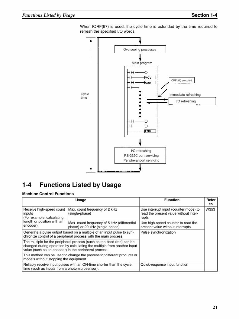
When IORF(97) is used, the cycle time is extended by the time required torefresh the specified I/O words.
1-4 Functions Listed by UsageMachine Control Functions
Cycletime
Overseeing processes
Main program
I/O refreshing
RS-232C port servicing
Peripheral port servicing
IORF(97) executed.
Immediate refreshing
I/O refreshing
Usage Function Refer to
Receive high-speed count inputs(For example, calculating length or position with an encoder).
Max. count frequency of 2 kHz (single-phase)
Use interrupt input (counter mode) to read the present value without inter-rupts.
W353
Max. count frequency of 5 kHz (differential phase) or 20 kHz (single-phase)
Use high-speed counter to read the present value without interrupts.
Generate a pulse output based on a multiple of an input pulse to syn-chronize control of a peripheral process with the main process.
Pulse synchronization
The multiple for the peripheral process (such as tool feed rate) can be changed during operation by calculating the multiple from another input value (such as an encoder) in the peripheral process.This method can be used to change the process for different products or models without stopping the equipment.
Reliably receive input pulses with an ON-time shorter than the cycle time (such as inputs from a photomicrosensor).
Quick-response input function
21

Functions Listed by Usage Section 1-4
Interrupt functions Execute a special process very quickly when an input goes ON.(For example, operating a cutter when an interrupt input is received from a Proximity Switch or Photoelectric Switch.)
Interrupt input (interrupt input mode) W353
Count input ON pulses and execute a spe-cial process very quickly when the count reaches the preset value.(For example, stopping the supply feed when a preset number of workpieces have passed through the system.)
Interrupt input (counter mode)
Execute a special process at a preset count value.(For example, cutting material very pre-cisely at a given length.)
High-speed counter interrupt gener-ated when the count matches the set value.
Execute a special process when the count is within a preset range.(For example, sorting material very quickly when it is within a given length range.)
High-speed counter interrupt gener-ated when the count is within the set range.
Execute a special process when a timer times out.(For example, stopping a conveyor at very precise time (independent of the cycle time) after the workpiece is detected.)
Interval timer interrupt(One-shot mode)
Repeat a special process at regular inter-vals.(For example, the speed of a sheet feeder can be monitored by measuring the input signal from an encoder at regular intervals and calculating the speed.)
Interval timer interrupt(Scheduled interrupt mode)
Perform simple positioning by outputting pulses to a motor driver that accepts pulse-train inputs.
Pulse output function
Receive an analog input and output an analog output. Analog I/O Unit(Connect the Analog I/O Unit to the CPU Unit.)
Receive temperature sensor input directly at the PC. Temperature Sensor Unit(Connect the Temperature Sensor Unit to the CPU Unit.)
Reduce required wiring, space, and PC load by controlling equipment with a few low-capacity PCs dispersed near the equipment rather than a single, large, centralized PC.(Create a remote I/O link with a CompoBus/S Master and CompoBus/S Slaves.)
CompoBus/S I/O Link Unit(Connect the CompoBus/S I/O Link Unit to the CPU Unit.)
Obtain data from SYSWAY-compatible temperature controllers, digital panel meters, or CompoWay/F-compatible general-purpose communi-cations components.
Simple Communications Unit(Connect the Simple Communications Unit to the CPU Unit.)
page221
Usage Function Refer to
22
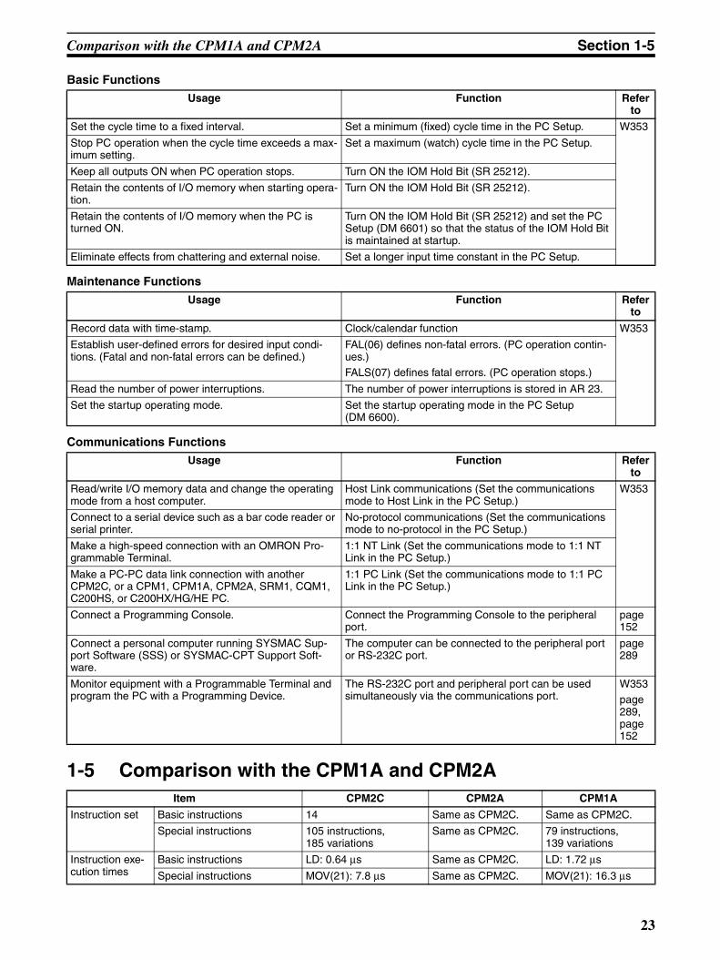
Comparison with the CPM1A and CPM2A Section 1-5
Basic Functions
Maintenance Functions
Communications Functions
1-5 Comparison with the CPM1A and CPM2A
Usage Function Refer to
Set the cycle time to a fixed interval. Set a minimum (fixed) cycle time in the PC Setup. W353
Stop PC operation when the cycle time exceeds a max-imum setting.
Set a maximum (watch) cycle time in the PC Setup.
Keep all outputs ON when PC operation stops. Turn ON the IOM Hold Bit (SR 25212).
Retain the contents of I/O memory when starting opera-tion.
Turn ON the IOM Hold Bit (SR 25212).
Retain the contents of I/O memory when the PC is turned ON.
Turn ON the IOM Hold Bit (SR 25212) and set the PC Setup (DM 6601) so that the status of the IOM Hold Bit is maintained at startup.
Eliminate effects from chattering and external noise. Set a longer input time constant in the PC Setup.
Usage Function Refer to
Record data with time-stamp. Clock/calendar function W353
Establish user-defined errors for desired input condi-tions. (Fatal and non-fatal errors can be defined.)
FAL(06) defines non-fatal errors. (PC operation contin-ues.)FALS(07) defines fatal errors. (PC operation stops.)
Read the number of power interruptions. The number of power interruptions is stored in AR 23.
Set the startup operating mode. Set the startup operating mode in the PC Setup (DM 6600).
Usage Function Refer to
Read/write I/O memory data and change the operating mode from a host computer.
Host Link communications (Set the communications mode to Host Link in the PC Setup.)
W353
Connect to a serial device such as a bar code reader or serial printer.
No-protocol communications (Set the communications mode to no-protocol in the PC Setup.)
Make a high-speed connection with an OMRON Pro-grammable Terminal.
1:1 NT Link (Set the communications mode to 1:1 NT Link in the PC Setup.)
Make a PC-PC data link connection with another CPM2C, or a CPM1, CPM1A, CPM2A, SRM1, CQM1, C200HS, or C200HX/HG/HE PC.
1:1 PC Link (Set the communications mode to 1:1 PC Link in the PC Setup.)
Connect a Programming Console. Connect the Programming Console to the peripheral port.
page152
Connect a personal computer running SYSMAC Sup-port Software (SSS) or SYSMAC-CPT Support Soft-ware.
The computer can be connected to the peripheral port or RS-232C port.
page289
Monitor equipment with a Programmable Terminal and program the PC with a Programming Device.
The RS-232C port and peripheral port can be used simultaneously via the communications port.
W353page289, page152
Item CPM2C CPM2A CPM1A
Instruction set Basic instructions 14 Same as CPM2C. Same as CPM2C.
Special instructions 105 instructions, 185 variations
Same as CPM2C. 79 instructions, 139 variations
Instruction exe-cution times
Basic instructions LD: 0.64 µs Same as CPM2C. LD: 1.72 µs
Special instructions MOV(21): 7.8 µs Same as CPM2C. MOV(21): 16.3 µs
23

Comparison with the CPM1A and CPM2A Section 1-5
Program capacity 4,096 words Same as CPM2C. 2,048 words
Maximum num-ber of I/O points
Stand-alone CPU Unit 10, 20, or 32 points 30, 40, or 60 points 10, 20, 30, or 40 points
CPU Unit with Expansion I/O Units
170, 180, or 192 points max.
90, 100, or 120 points max.
90 or 100 points max.
Expansion Units and Expansion I/O Units
Maximum number of Units A maximum of 5 Units can be connected to any of the CPU Units.
A maximum of 3 Units can be connected to any of the CPU Units.
A maximum of 3 Units can be connected to the 30-point and 40-point CPU Units.
Available models Expansion I/O Units, Analog I/O Unit, Temper-ature Sensor Unit, Com-poBus/S I/O Link Unit, and Simple Communica-tions Unit
Same as CPM2C. Same as CPM2C.
I/O memory Input bits IR 00000 to IR 00915 Same as CPM2C. Same as CPM2C.
Output bits IR 01000 to IR 01915 Same as CPM2C. Same as CPM2C.
Work bits 928 bits:IR 02000 to IR 04915,IR 20000 to IR 22715
Same as CPM2C. 512 bits:IR 20000 to IR 23115
SR (Special Relay) area 448 bits:SR 22800 to SR 25515
Same as CPM2C. 384 bits:SR 23200 to SR 25515
TR (Temporary Relay) area 8 bits: TR0 to TR7 Same as CPM2C. Same as CPM2C.
HR (Holding Relay) area 320 bits:HR 0000 to HR 1915
Same as CPM2C.
AR (Auxiliary Relay) area 384 bits:AR 0000 to AR 2315
Same as CPM2C. 256 bits:AR 0000 to AR 1515
LR (Link Relay) area 256 bits:LR 0000 to LR 1515
Same as CPM2C. Same as CPM2C.
Timer/Counter area 256 bits:TIM/CNT 000 to TIM/CNT 255
Same as CPM2C. 128 bits:TIM/CNT 0 to TIM/CNT 127
DM (Data Memory) area
Read/write area
2,048 words(DM 0000 to DM 2047)
Same as CPM2C. 1,024 words(DM 0000 to DM 1023)
Read-only area
456 words(DM 6144 to DM 6599)
Same as CPM2C. Same as CPM2C.
PC Setup 56 words(DM 6600 to DM 6655)
Same as CPM2C. Same as CPM2C.
Memory backup Program area, read-only DM area (including PC Setup)
Flash memory backup Same as CPM2C. Same as CPM2C.
Read/write DM area, HR area, AR area, and counters
CPU Unit with clock:Internal battery backup (2-year lifetime at 25°C, replaceable)
CPU Unit without clock: Capacitor backup (10-day backup at 25°C) or optional battery backup (5 years at 25°C, replaceable)
Internal battery backup(5-year lifetime at 25°C, replaceable)
Capacitor backup(20-day backup at 25°C)
Interrupt inputs (interrupt input mode) 4 (20-/32-point CPU Unit),2 (10-point CPU Unit)
4 4
Item CPM2C CPM2A CPM1A
24

Comparison with the CPM1A and CPM2A Section 1-5
Interrupt inputs (counter mode)
Counter mode Incrementing counterDecrementing counter
Same as CPM2C. Decrementing counter
Counter upper limit 2 kHz Same as CPM2C. 1 kHz
SR 244 to SR 247 Contains counter PV. Same as CPM2C. Contains counter PV–1.
Method(s) to read counter PV
Read SR 244 to SR 247.Execute PRV(62).
Same as CPM2C. Read SR 244 to SR 247.(Counter PV – 1)
Method to change counter PV
Execute INI(61). Same as CPM2C. Not supported.
Interval timer One-shot mode Yes Same as CPM2C. Same as CPM2C.
Scheduled interrupt mode Yes Same as CPM2C. Same as CPM2C.
Item CPM2C CPM2A CPM1A
Item CPM2C/CPM2A CPM1A
Quick-response inputs
Setting the quick-response function
PC Setup PC Setup and INT(89) (Unmask interrupt input.)
INT(89) (Mask) Not supported (ignored) Supported.
INT(89) (Read mask) Reads mask status. Reads result of mask set-ting.
INT(89) (Clear) Not supported (ignored) Supported.
Minimum pulse width 50 µs min. 200 µs min.
High-speed counter
Count mode Differential-phase (up/down) modePulse plus direction modeUp/down pulse modeIncrement mode
Differential-phase (up/down) modeIncrement mode
Max. counter frequency 5 kHz in differential-phase (up/down) mode20 kHz in pulse plus direction mode, up/down pulse mode, and increment mode
2.5 kHz in differential-phase (up/down) mode,5 kHz in increment mode
Counter PV range –8,388,608 to 8,388,607 in differential-phase (up/down) mode, pulse plus direc-tion mode, and up/down pulse mode0 to 16,777,215 in increment mode
–32,768 to 32,767 in differential-phase (up/down) mode0 to 65,535 in increment mode
Check when registering tar-get value match table
Same direction, same SV not possible Same direction, same SV possible
Method used to reference the target value match interrupt table
Comparison of all values in the table, regardless of order of appearance in table
Comparison in order of appearance in table
Reading range-comparison results
Check AR 1100 to AR 1107 or execute PRV(62).
Check AR 1100 to AR 1107.
Reading status Check AR 1108 (comparison in progress), check AR 1109 (high-speed counter PV overflow/underflow), or execute PRV(62).
---
Pulse synchronization Supported. Not supported.
25

Comparison with the CPM1A and CPM2A Section 1-5
Note The setting of SW2 will affect the operating mode for all Units with lot numbersof 3180O (31 August 2000) or earlier. Refer to 1-7 Changes in SW2 fordetails.
Pulse output control
Trapezoidal acceleration/ deceleration
Supported with ACC(−−). The initial fre-quency can be set.
Not supported.
PWM(−−) output Supported. Not supported.
Number of simultaneous pulse outputs
2 max. 1 max.
Maximum frequency 10 kHz max. 2 kHz max.
Minimum frequency 10 Hz 20 Hz
Pulse output quantity –16,777,215 to 16,777,215 0 to 16,777,215
Direction control Supported. Not supported.
Positioning to absolute posi-tions
Supported. Not supported.
Bit status while pulses are being output
No effect Turned ON/OFF by pulse output
Reading PV Read SR 228 through SR 231 or execute PRV(62).
Not supported.
Resetting PV Supported. Not supported.
Status outputs Accelerating/deceleratingPV overflow/underflowPulse quantity setPulse output completedPulse output status
Pulse output status
Item CPM2C/CPM2A CPM1A
Item CPM2C CPM2A CPM1A
Analog controls None 2 2
Clock function Internal or none Internal None
Words containing time info.
AR 17 to AR 21 AR 17 to AR 21 ---
Analog I/O Analog I/O Units can be connected.
Same as CPM2C. Same as CPM2C.
Temperature monitoring The CPU Unit can receive temperature sensor input from either thermocouples or platinum resistance ther-mometers.
Same as CPM2C. Same as CPM2C.
CompoBus/S communications A CompoBus/S I/O Link Unit can be connected to provide CompoBus/S Slave func-tions.
Same as CPM2C. Same as CPM2C.
Communications switch This switch determines whether communications are governed by the stan-dard settings or PC Setup settings. Also sets the Pro-gramming Device connec-tion. (See note.)
This switch determines whether communica-tions are governed by the standard settings or PC Setup settings.
None
26

Comparison with the CPM1A and CPM2A Section 1-5
Note 1. An optional battery (CPM2C-BAT01) can be mounted to CPU Units withoutclocks.
2. The setting of SW2 will affect the operating mode for all Units with lot num-bers of 3180O (31 August 2000) or earlier. Refer to 1-7 Changes in SW2for details.
Item CPM2C CPM2A CPM1A
Battery Battery CPU Unit with clock:Internal lithium battery backupCPU Unit without clock: Capacitor backup or optional lithium battery backup
Lithium None (capacitor backup only)
Battery replace-ment
Possible Possible ---
Life expectancy/backup time
CPU Unit with clock: 2-year lifetime at 25°CCPU Unit without clock (capacitor): 10-day backup at 25°C CPU Unit without clock (lith-ium battery): 5-year lifetime at 25°C
5-year lifetime at 25°C 20-day backup at 25°C
Battery error detec-tion
Supported. Same as CPM2C. ---
Communications (in CPU Unit)
Peripheral port (via communications port)
Programming Console(automatically detected) (See note 2.)Peripheral bus(automatically detected)Host Link (with Slave-initi-ated communications)No-protocol
Programming Console (auto-detect)Peripheral bus (auto-detect)Host Link (with Slave-initiated communica-tions)No-protocol
Programming Console (auto-detect)Peripheral bus (auto-detect)Host Link1:1 PC LInk1:1 NT Link
RS-232C port (via communications port)
Peripheral bus (Set with Communications Switch.)Host LinkNo-protocol1:1 PC LInk1:1 NT Link
Peripheral bus (auto-detect)Host LinkNo-protocol1:1 PC LInk1:1 NT Link
None
Input time constant Can be set to 1, 2, 3, 5, 10, 20, 40, or 80 ms. (Default: 10 ms)
Same as CPM2C. Can be set to 1, 2, 4, 8, 16, 32, 64, or 128 ms. (Default: 8 ms)
27

Comparison with the CPM1A and CPM2A Section 1-5
Differences in Instruction Sets
Instructions added to the CPM2C
Instructions with Changed Specifications
Mnemonic Name
TXD(48) TRANSMIT
RXD(47) RECEIVE
SCL(66) SCALING
SCL2(−−) SIGNED BINARY TO BCD SCALING
SCL3(−−) BCD TO SIGNED BINARY SCALING
SRCH(−−) DATA SEARCH
MAX(−−) FIND MAXIMUM
MIN(−−) FIND MINIMUM
SUM(−−) SUM CALCULATION
FCS(−−) FCS CALCULATE
HEX(−−) ASCII-TO-HEXADECIMAL
AVG(−−) AVERAGE VALUE
PWM(−−) PULSE WITH VARIABLE DUTY RATIO
PID(−−) PID CONTROL
ZCP(−−) AREA RANGE COMPARE
ZCPL(−−) DOUBLE AREA RANGE COMPARE
NEG(−−) 2’S COMPLEMENT
ACC(−−) ACCELERATION Control
STUP(−−) CHANGE RS-232C SETUP
SYNC(−−) SYNCHRONIZED PULSE CONTROL
BINL(58) DOUBLE BCD TO DOUBLE BINARY
BCDL(59) Double binary to double bcd
TMHH(−−) VERY HIGH-SPEED TIMER
TIML(−−) LONG TIMER
SEC(−−) HOURS-TO-SECONDS
HMS(−−) SECONDS-TO-HOURS
Mnemonic Name CPM2C CPM1A
INI(61) MODE CONTROL Supports the interrupt input (counter mode) PV change operation.
Supports the pulse output PV change operation.Supports the pulse synchronization control stop operation.
Does not support these operations.
PRV(62) HIGH-SPEED COUNTER PV READ
Supports the interrupt input (counter mode) PV read operation.
Supports the pulse output PV read operation.
Does not support these operations.
CTBL(63) COMPARISON TABLE LOAD
The count is compared with all of the target values in the target value comparison table.
The count is compared with each target value in the order that they appear in the target value comparison table.
PULS(65) SET PULSES Supports absolute pulse specification, but the coordi-nate system must be set to absolute coordinates.
Does not support abso-lute pulse specification.
INT(89) Interrupt control Supports a count-up interrupt for incrementing counters.
Does not support this interrupt function.
28

Comparison with the CPM1A and CPM2A Section 1-5
!Caution Before using a CPM1A program containing one or more of the instructions inthe table above, check the program to be sure that it will operate properly andedit the program if necessary. The CPM2C may not operate properly if aCPM1A program with these instructions is transferred and executedunchanged.
Added Function Code Allocations
The following three instructions are allocated function codes that were notused in the CPM1A.
Differences in I/O Memory
SR Area Differences The following table shows differences in the SR area. (PV is the abbreviationfor present value.)
AR Area Differences The following table shows differences in the AR area.
Note CPM1A programs that use AR 10 (the Power OFF Counter) cannot be used inthe CPM2C without editing the program. In the CPM2C, the Power OFFCounter is in AR 23.
Instruction CPM2C CPM1A
RXD(47) RECEIVE Not allocated. (NOP(00))
TXD(48) TRANSMIT
SCL(66) SCALING
Function CPM2C CPM1A
Pulse output 0 PV SR 228 to SR 229 Not sup-ported.Pulse output 1 PV SR 230 to SR 231
Pulse output 0 PV Reset Bit SR 25204
Pulse output 1 PV Reset Bit SR 25205
RS-232C Port Reset Bit SR 25209
Battery Error Flag SR 25308
Changing RS-232C Port Setup Flag SR 25312
Function CPM2C CPM1A
Clock/calendar data AR 17 to AR 21 Not sup-ported.RS-232C Communications Error Code AR 0800 to AR 0803
RS-232C Error Flag AR 0804
RS-232C Transmission Enabled Flag AR 0805
RS-232C Reception Completed Flag AR 0806
RS-232C Reception Overflow Flag AR 0807
Peripheral Port Reception Completed Flag AR 0814
Peripheral Port Reception Overflow Flag AR 0815
RS-232C Reception Counter AR 09
High-speed Counter Comparison Flag AR 1108
High-speed Counter Overflow/Underflow Flag AR 1109
Pulse Output 0 Output Condition AR 1111
Pulse Output 0 PV Overflow/Underflow Flag AR 1112
Pulse Output 0 Pulse Quantity Set Flag AR 1113
Pulse Output 0 Output Completed Flag AR 1114
Pulse Output 1 PV Overflow/Underflow Flag AR 1212
Pulse Output 1 Pulse Quantity Set Flag AR 1213
Pulse Output 1 Output Completed Flag AR 1214
Pulse Output 1 Output Status AR 1215
Power OFF Counter AR 23 (See note.) AR 10
29

Preparation for Operation Section 1-6
DM Area Differences The following table shows differences in the DM area other than the PCSetup.
Note CPM1A programs that use the Error Log Area cannot be used in the CPM2Cwithout editing the program to change the location of the Error Log Area.
The following table shows differences in the PC Setup.
1-6 Preparation for OperationFollow the steps listed below when setting up a CPM2C system.
1,2,3... 1. System Design• Select a CPM2C CPU Unit, Expansion Units, and Expansion I/O Units
with the specifications required in the controlled system.• Design external fail-safe circuits such as interlock circuits and limit cir-
cuits.Refer to 2-1 Specifications and 3-1 Design Precautions for details.
2. Installation• Connect the Expansion Units and Expansion I/O Units.• Install the CPU Unit. (DIN-track installation)
Refer to 3-3 Installing the CPM2C and 3-4 Wiring and Connections for de-tails.
3. Wiring• Wire the power supply and I/O devices.• Connect communications devices if necessary.• Connect the Programming Console.
Function CPM2C CPM1A
Error Log Area DM 2000 to DM 2021 DM 1000 to DM 1021
Function CPM2C CPM1A
RS-232C Port Servicing Time Setting DM 6616 bits 00 to 07 Not sup-portedRS-232C Port Servicing Time Enable DM 6616 bits 08 to 15
Pulse Output 0 Coordinate System DM 6629 bits 00 to 03
Pulse Output 1 Coordinate System DM 6629 bits 04 to 07
RS-232C Communications Settings Selector DM 6645 bits 00 to 03
RS-232C Port CTS Control Settings DM 6645 bits 04 to 07
RS-232C Port Link Words for 1:1 PC Link DM 6645 bits 08 to 11
RS-232C Port Communications Mode DM 6645 bits 12 to 15
RS-232C Port Baud Rate DM 6646 bits 00 to 07
RS-232C Port Frame Format DM 6646 bits 08 to 15
RS-232C Port Transmission Delay DM 6647
RS-232C Port Host Link Node Number DM 6648 bits 00 to 07
RS-232C Port No-protocol Start Code Enable DM 6648 bits 08 to 11
RS-232C Port No-protocol End Code Enable DM 6648 bits 12 to 15
RS-232C Port No-protocol Start Code Setting DM 6649 bits 00 to 07
RS-232C Port No-protocol End Code Setting or Number of Bytes Received
DM 6649 bits 08 to 15
Peripheral Port No-protocol Start Code Enable DM 6653 bits 08 to 11
Peripheral Port No-protocol End Code Enable DM 6653 bits 12 to 15
Peripheral Port No-protocol Start Code Setting DM 6654 bits 00 to 07
Peripheral Port No-protocol End Code Setting or Number of Bytes Received
DM 6654 bits 08 to 15
Battery Error Detect Setting DM 6655 bits 12 to 15
30
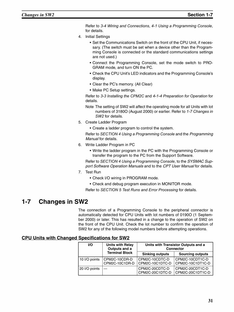
Changes in SW2 Section 1-7
Refer to 3-4 Wiring and Connections, 4-1 Using a Programming Console,for details.
4. Initial Settings
• Set the Communications Switch on the front of the CPU Unit, if neces-sary. (The switch must be set when a device other than the Program-ming Console is connected or the standard communications settingsare not used.)
• Connect the Programming Console, set the mode switch to PRO-GRAM mode, and turn ON the PC.
• Check the CPU Unit’s LED indicators and the Programming Console’sdisplay.
• Clear the PC’s memory. (All Clear)
• Make PC Setup settings.
Refer to 3-3 Installing the CPM2C and 4-1-4 Preparation for Operation fordetails.
Note The setting of SW2 will affect the operating mode for all Units with lotnumbers of 3180O (August 2000) or earlier. Refer to 1-7 Changes inSW2 for details.
5. Create Ladder Program
• Create a ladder program to control the system.
Refer to SECTION 4 Using a Programming Console and the ProgrammingManual for details.
6. Write Ladder Program in PC
• Write the ladder program in the PC with the Programming Console ortransfer the program to the PC from the Support Software.
Refer to SECTION 4 Using a Programming Console, to the SYSMAC Sup-port Software Operation Manuals and to the CPT User Manual for details.
7. Test Run
• Check I/O wiring in PROGRAM mode.
• Check and debug program execution in MONITOR mode.
Refer to SECTION 5 Test Runs and Error Processing for details.
1-7 Changes in SW2The connection of a Programming Console to the peripheral connector isautomatically detected for CPU Units with lot numbers of 0190O (1 Septem-ber 2000) or later. This has resulted in a change to the operation of SW2 onthe front of the CPU Unit. Check the lot number to confirm the operation ofSW2 for any of the following model numbers before attempting operations.
CPU Units with Changed Specifications for SW2I/O Units with Relay
Outputs and a Terminal Block
Units with Transistor Outputs and a Connector
Sinking outputs Sourcing outputs
10 I/O points CPM2C-10CDR-DCPM2C-10C1DR-D
CPM2C-10CDTC-DCPM2C-10C1DTC-D
CPM2C-10CDT1C-DCPM2C-10C1DT1C-D
20 I/O points --- CPM2C-20CDTC-DCPM2C-20C1DTC-D
CPM2C-20CDT1C-DCPM2C-20C1DT1C-D
31

Changes in SW2 Section 1-7
Interpreting Lot Numbers
Operating Previous CPU UnitsThe following instructions apply to CPU Units with lot numbers of 3180O(August 2000) or earlier.
The previous CPU Units do not detect a Programming Console connected tothe peripheral port, and SW2 of the DIP switch was used to set either “Pro-gramming Console” or “Other device.”
SW2 Setting
The relationship between the PC Setup settings, the setting of SW2, and thestartup operating mode for previous CPU Units is shown in the following table.
Note 1. The default setting for DM 6600, bits 06 to 15 is 00 Hex, i.e., according tothe communications switch on the front panel. If SW2 is set for connectinga device other than a Programming Console to the peripheral connector,
Lot No. 31 8 0 O
Year: Rightmost digit (2000 = 0)
Month: JAN to SEP = 1 to 9 OCT to DEC = X to Z
Day: 1 to 31
Factor identification symbol(Appears only on the side of the product.)
SW1 SW2 Peripheral port RS-232C port
OFF OFF Programming Console connec-tion
According to PC Setup in DM 6645 to DM 6649.
OFF ON Connection other than to Pro-gramming Console according to PC Setup in DM 6650 to DM 6654.
According to PC Setup in DM 6645 to DM 6649.
ON OFF Programming Console connec-tion
According to standard settings.
ON ON Connection other than to Pro-gramming Console according to standard settings.
According to standard settings.
Communications Switch
PRO
ON ON
SW1 SW2
PC Setup CPM2C Operating Mode
Address Bits Setting
DM6600 08 to 15 00 Hex According to communications switch SW2 and peripheral port device.
Peripheral device SW2 setting
OFF ON
Nothing connected PROGRAM mode RUN mode
Programming Con-sole
According to Programming Console key switch.
PROGRAM mode(See note.)
Other PROGRAM mode (See note.)
PROGRAM mode
Note: Communications will not be possible between the CPM2C and the peripheral device for these combinations.
01 Hex Mode used immediately before power interruption
02 Hex Mode specified in bits 00 to 07.
00 to 07 00 Hex PROGRAM mode
01 Hex MONITOR mode
02 Hex RUN mode
32

Changes in SW2 Section 1-7
the CPU Unit will start in RUN mode as soon as power is turned ON. Besure that adequate precautions are taken to ensure safety.
2. If SW2 is for connecting a device other than a Programming Console to theperipheral connector, the CPU Unit will start in RUN mode as soon as pow-er is turned ON even if a device is connected to the RS-232C port. Be surethat adequate precautions are taken to ensure safety.
Connections
IBM PC/AT or compatible
XW2Z-200S-VXW2Z-500S-V
CPM2C-CN111
CS1W-CN118
CPM2C-CIF01-V1
33

SECTION 2Unit Components and Specifications
This section describes the main components of the Units that go together to create a CPM2C PC and provides the technicalspecifications of the Units.
2-1 Specifications . . . . . . . . . . . . . . . . . . . . . . . . . . . . . . . . . . . . . . . . . . . . . . . . . 36
2-1-1 General Specifications . . . . . . . . . . . . . . . . . . . . . . . . . . . . . . . . . . . 36
2-1-2 Characteristics. . . . . . . . . . . . . . . . . . . . . . . . . . . . . . . . . . . . . . . . . . 36
2-1-3 I/O Specifications . . . . . . . . . . . . . . . . . . . . . . . . . . . . . . . . . . . . . . . 38
2-1-4 AC Power Supply Unit Specifications . . . . . . . . . . . . . . . . . . . . . . . 46
2-2 Unit Components . . . . . . . . . . . . . . . . . . . . . . . . . . . . . . . . . . . . . . . . . . . . . . 47
2-2-1 CPU Unit Components . . . . . . . . . . . . . . . . . . . . . . . . . . . . . . . . . . . 47
2-2-2 Expansion I/O Units . . . . . . . . . . . . . . . . . . . . . . . . . . . . . . . . . . . . . 59
2-2-3 CPM2C-MAD11 Analog I/O Unit . . . . . . . . . . . . . . . . . . . . . . . . . . 69
2-2-4 CPM2C-TS001/TS101 Temperature Sensor Units. . . . . . . . . . . . . . 70
2-2-5 CPM2C-SRT21 CompoBus/S I/O Link Unit . . . . . . . . . . . . . . . . . . 72
2-2-6 CPM2C-CIF21 Simple Communications Unit. . . . . . . . . . . . . . . . . 73
2-2-7 CPM2C-CIF01-V1 Peripheral/RS-232C Adapter Unit . . . . . . . . . . 77
2-2-8 CPM2C-CIF11 RS-422/RS-232C Adapter Unit . . . . . . . . . . . . . . . 79
2-2-9 AC Power Supply Unit . . . . . . . . . . . . . . . . . . . . . . . . . . . . . . . . . . . 82
35
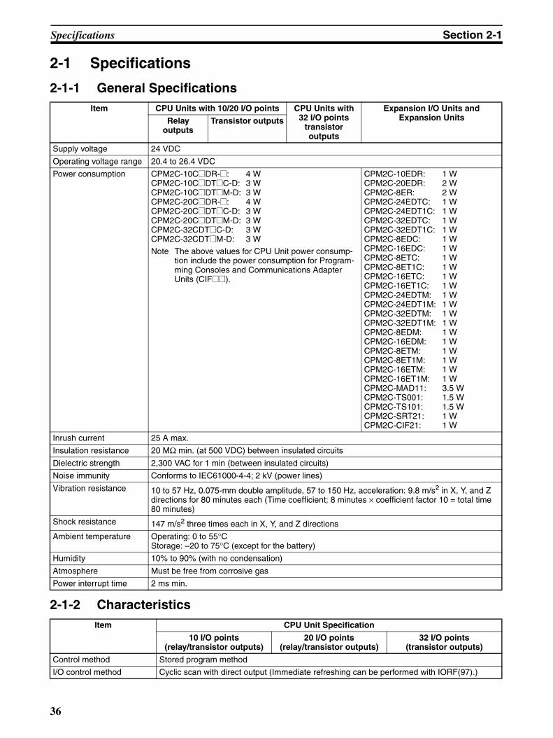
Specifications Section 2-1
2-1 Specifications
2-1-1 General Specifications
2-1-2 Characteristics
Item CPU Units with 10/20 I/O points CPU Units with32 I/O points
transistor outputs
Expansion I/O Units and Expansion UnitsRelay
outputsTransistor outputs
Supply voltage 24 VDC
Operating voltage range 20.4 to 26.4 VDC
Power consumption CPM2C-10C@DR-@: 4 WCPM2C-10C@DT@C-D: 3 WCPM2C-10C@DT@M-D: 3 WCPM2C-20C@DR-@: 4 WCPM2C-20C@DT@C-D: 3 WCPM2C-20C@DT@M-D: 3 WCPM2C-32CDT@C-D: 3 WCPM2C-32CDT@M-D: 3 W
Note The above values for CPU Unit power consump-tion include the power consumption for Program-ming Consoles and Communications Adapter Units (CIF@@).
CPM2C-10EDR: 1 WCPM2C-20EDR: 2 WCPM2C-8ER: 2 WCPM2C-24EDTC: 1 WCPM2C-24EDT1C: 1 WCPM2C-32EDTC: 1 WCPM2C-32EDT1C: 1 WCPM2C-8EDC: 1 WCPM2C-16EDC: 1 WCPM2C-8ETC: 1 WCPM2C-8ET1C: 1 WCPM2C-16ETC: 1 WCPM2C-16ET1C: 1 WCPM2C-24EDTM: 1 WCPM2C-24EDT1M: 1 WCPM2C-32EDTM: 1 WCPM2C-32EDT1M: 1 WCPM2C-8EDM: 1 WCPM2C-16EDM: 1 WCPM2C-8ETM: 1 WCPM2C-8ET1M: 1 WCPM2C-16ETM: 1 WCPM2C-16ET1M: 1 WCPM2C-MAD11: 3.5 WCPM2C-TS001: 1.5 WCPM2C-TS101: 1.5 WCPM2C-SRT21: 1 WCPM2C-CIF21: 1 W
Inrush current 25 A max.
Insulation resistance 20 MΩ min. (at 500 VDC) between insulated circuits
Dielectric strength 2,300 VAC for 1 min (between insulated circuits)
Noise immunity Conforms to IEC61000-4-4; 2 kV (power lines)
Vibration resistance 10 to 57 Hz, 0.075-mm double amplitude, 57 to 150 Hz, acceleration: 9.8 m/s2 in X, Y, and Z directions for 80 minutes each (Time coefficient; 8 minutes × coefficient factor 10 = total time 80 minutes)
Shock resistance 147 m/s2 three times each in X, Y, and Z directions
Ambient temperature Operating: 0 to 55°CStorage: –20 to 75°C (except for the battery)
Humidity 10% to 90% (with no condensation)
Atmosphere Must be free from corrosive gas
Power interrupt time 2 ms min.
Item CPU Unit Specification
10 I/O points(relay/transistor outputs)
20 I/O points(relay/transistor outputs)
32 I/O points(transistor outputs)
Control method Stored program method
I/O control method Cyclic scan with direct output (Immediate refreshing can be performed with IORF(97).)
36

Specifications Section 2-1
Programming language Ladder diagram
Instruction length 1 step per instruction, 1 to 5 words per instruction
Instructions Basic instructions: 14 Special instructions: 105 instructions, 185 variations
Execution time Basic instructions: 0.64 µs (LD instruction)Special instructions: 7.8 µs (MOV instruction)
Program capacity 4,096 words
Max. I/O capacity
CPU Unit only 10 points 20 points 32 points
With Expansion I/O Units and Expansion Units
170 points max. 180 points max. 192 points max.
Input bits IR 00000 to IR 00915 (Words not used for input bits can be used for work bits.)
Output bits IR 01000 to IR 01915 (Words not used for output bits can be used for work bits.)
Work bits 928 bits: IR 02000 to IR 04915 and IR 20000 to IR 22715
Special bits (SR area) 448 bits: SR 22800 to SR 25515
Temporary bits (TR area) 8 bits (TR0 to TR7)
Holding bits (HR area) 320 bits: HR 0000 to HR 1915 (Words HR 00 to HR 19)
Auxiliary bits (AR area) 384 bits: AR 0000 to AR 2315 (Words AR 00 to AR 23)
Link bits (LR area) 256 bits: LR 0000 to LR 1515 (Words LR 00 to LR 15)
Timers/Counters 256 timers/counters (TIM/CNT 000 to TIM/CNT 255)1-ms timers: TMHH(−−)10-ms timers: TIMH(15)100-ms timers: TIM1-s/10-s timers: TIML(−−)Decrementing counters: CNTReversible counters: CNTR(12)
Data memory Read/Write: 2,048 words (DM 0000 to DM 2047)*Read-only: 456 words (DM 6144 to DM 6599)PC Setup: 56 words (DM 6600 to DM 6655)*The Error Log is contained in DM 2000 to DM 2021.
Interrupt processing 2 interrupts 4 interrupts 4 interrupts
Shared by the external interrupt inputs (counter mode) and the quick-response inputs.
Interval timer interrupts 1 (Scheduled Interrupt Mode or Single Interrupt Mode)
High-speed counter One high-speed counter: 20 kHz single-phase or 5 kHz two-phase (linear count method)
Counter interrupt: 1 (set value comparison or set-value range comparison)
Interrupt Inputs(Counter mode)
2 inputs 4 inputs 4 inputs
Shared by the external interrupt inputs and the quick-response inputs.
Pulse output Two points with no acceleration/deceleration, 10 Hz to 10 kHz each, and no direction control.One point with trapezoid acceleration/deceleration, 10 Hz to 10 kHz, and direction control.Two points with variable duty-ratio outputs.(Pulse outputs can be used with transistor outputs only, they cannot be used with relay out-puts.)
Synchronized pulse control One point:A pulse output can be created by combining the high-speed counter with pulse outputs and multiplying the frequency of the input pulses from the high-speed counter by a fixed factor.(This output is possible with transistor outputs only, it cannot be used with relay outputs.)
Quick-response inputs 2 inputs 4 inputs 4 inputs
Shared by the external interrupt inputs and the interrupt inputs (counter mode).Min. input pulse width: 50 µs max.
Input time constant(ON response time = OFF response time)
Can be set for all input points.(1 ms, 2 ms, 3 ms, 5 ms, 10 ms, 20 ms, 40 ms, or 80 ms)
Item CPU Unit Specification
10 I/O points(relay/transistor outputs)
20 I/O points(relay/transistor outputs)
32 I/O points(transistor outputs)
37

Specifications Section 2-1
Note 1. The DM area, HR area, AR area, and counter values are backed up. If thebackup battery or capacitor is discharged, the contents of these areas willbe lost and the data values will revert to the defaults.
2. The contents of the program area, read-only DM area (DM 6144 toDM 6599), and PC Setup (DM 6600 to DM 6655) are stored in flash mem-ory. The contents of these areas will be read from flash memory the nexttime the power is turned ON, even if the backup battery or capacitor is dis-charged.
When data has been changed in any of these areas, write the new valuesto flash memory by switching the CPM2C to MONITOR or RUN mode, orby turning the power OFF and then ON again.
2-1-3 I/O Specifications
CPU Unit Input Specifications
Clock function Shows the year, month, day of the week, day, hour, minute, and second. (Battery backup) The CPU Units with “C1” in the model number have a built-in clock.
Not provided on CPU Units with 32 I/O points.
Communications functions A CPM2C-CN111, CS1W-CN114, or CS1W-CN118 Connecting Cable is required to connect to the CPM2C’s communications port. The communications port can be used as both a peripheral and RS-232C port.Peripheral port:Supports Host Link, peripheral bus, no-protocol, or Programming Console connections.
RS-232C port:Supports Host Link, no-protocol, 1:1 Slave Unit Link, 1:1 Master Unit Link, or 1:1 NT Link connections.
Functions provided by Expansion Units
Analog I/O Unit: Provides 2 analog inputs and 1 analog output.Temperature Sensor Unit: Provides up to 8 thermocouple or platinum resistance thermome-ter inputs.CompoBus/S I/O Link Unit: Provides 8 inputs and 8 outputs as a CompoBus/S Slave.
Memory protection(See notes 1 and 2.)
HR area, AR area, program contents, read/write DM area contents, and counter values maintained during power interruptions.
Memory backup(See notes 1 and 2.)
Flash memory:Program, read-only DM area, and PC SetupMemory backup:The read/write DM area, HR area, AR area, and counter values are backed up.
CPU Unit with clock (battery): 2-year lifetime at 25°CCPU Unit without clock (capacitor): 10-day backup at 25°C CPU Unit without clock (lithium battery): 5-year lifetime at 25°C
Self-diagnostic functions CPU Unit failure (watchdog timer), I/O bus error, battery error, and memory failure
Program checks No END instruction, programming errors (checked when operation is started)
Item CPU Unit Specification
10 I/O points(relay/transistor outputs)
20 I/O points(relay/transistor outputs)
32 I/O points(transistor outputs)
Item Inputs Specification
Units with 10 I/O pts Units with 20 I/O pts Units with 32 I/O pts
Input voltage All 24 VDC +10%/–15%
Input impedance IN00000 to IN00001 2.7 kΩIN00002 to IN00004 3.9 kΩ --- ---
IN00002 to IN00006 --- 3.9 kΩ 3.9 kΩIN00005 4.7 kΩ --- ---
IN00007 and up --- 4.7 kΩ 4.7 kΩ
38
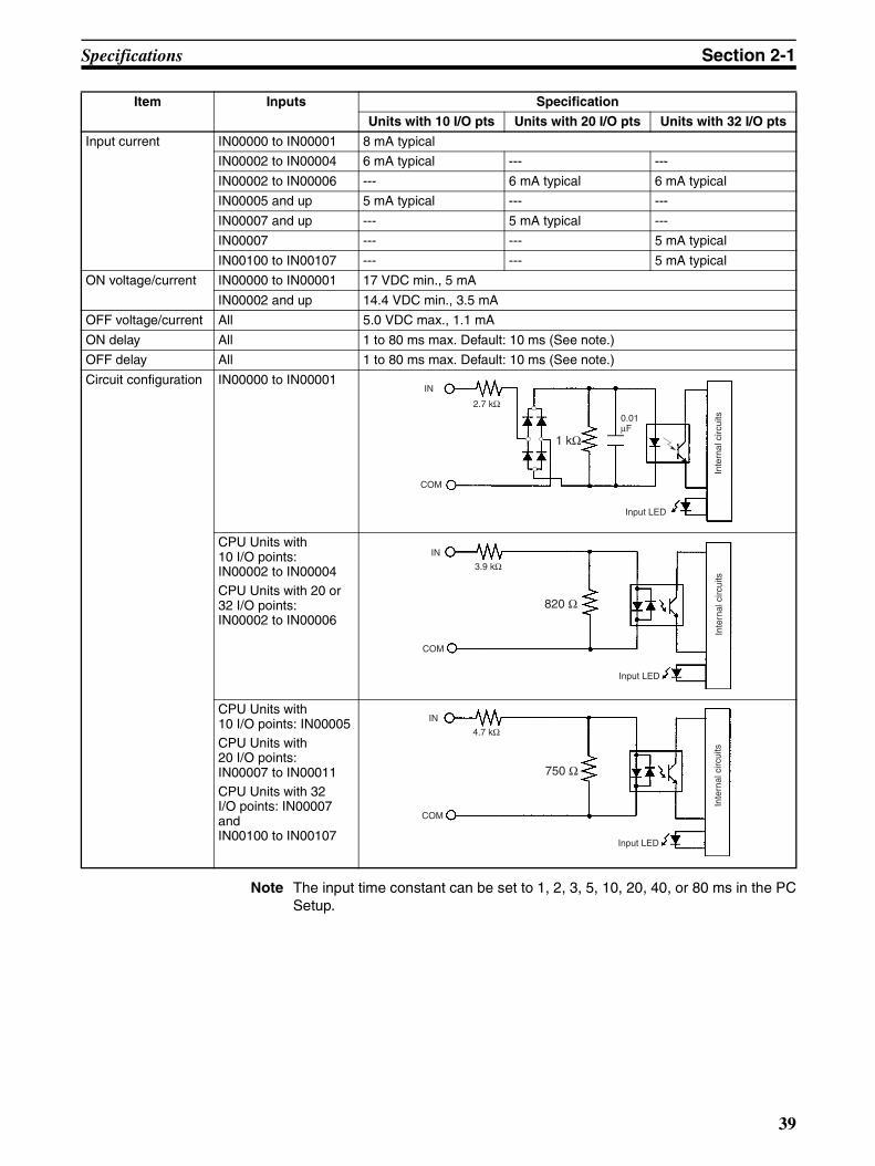
Specifications Section 2-1
Note The input time constant can be set to 1, 2, 3, 5, 10, 20, 40, or 80 ms in the PCSetup.
Input current IN00000 to IN00001 8 mA typical
IN00002 to IN00004 6 mA typical --- ---
IN00002 to IN00006 --- 6 mA typical 6 mA typical
IN00005 and up 5 mA typical --- ---
IN00007 and up --- 5 mA typical ---
IN00007 --- --- 5 mA typical
IN00100 to IN00107 --- --- 5 mA typical
ON voltage/current IN00000 to IN00001 17 VDC min., 5 mA
IN00002 and up 14.4 VDC min., 3.5 mA
OFF voltage/current All 5.0 VDC max., 1.1 mA
ON delay All 1 to 80 ms max. Default: 10 ms (See note.)
OFF delay All 1 to 80 ms max. Default: 10 ms (See note.)
Circuit configuration IN00000 to IN00001
CPU Units with 10 I/O points: IN00002 to IN00004CPU Units with 20 or 32 I/O points: IN00002 to IN00006
CPU Units with 10 I/O points: IN00005CPU Units with 20 I/O points: IN00007 to IN00011CPU Units with 32 I/O points: IN00007 and IN00100 to IN00107
Item Inputs Specification
Units with 10 I/O pts Units with 20 I/O pts Units with 32 I/O pts
1 kΩ
IN
COM
2.7 kΩ
Input LED
Inte
rnal
circ
uits0.01
µF
820 Ω
IN
COM
3.9 kΩ
Input LED
Inte
rnal
circ
uits
750 Ω
IN
COM
4.7 kΩ
Input LED
Inte
rnal
circ
uits
39
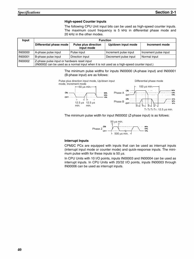
Specifications Section 2-1
High-speed Counter Inputs
The following CPU Unit input bits can be used as high-speed counter inputs.The maximum count frequency is 5 kHz in differential phase mode and20 kHz in the other modes.
The minimum pulse widths for inputs IN00000 (A-phase input) and IN00001(B-phase input) are as follows:
The minimum pulse width for input IN00002 (Z-phase input) is as follows:
Interrupt Inputs
CPM2C PCs are equipped with inputs that can be used as interrupt inputs(interrupt input mode or counter mode) and quick-response inputs. The mini-mum pulse width for these inputs is 50 µs.
In CPU Units with 10 I/O points, inputs IN00003 and IN00004 can be used asinterrupt inputs. In CPU Units with 20/32 I/O points, inputs IN00003 throughIN00006 can be used as interrupt inputs.
Input Function
Differential phase mode Pulse plus direction input mode
Up/down input mode Increment mode
IN00000 A-phase pulse input Pulse input Increment pulse input Increment pulse input
IN00001 B-phase pulse input Direction input Decrement pulse input Normal input
IN00002 Z-phase pulse input or hardware reset input(IN00002 can be used as a normal input when it is not used as a high-speed counter input.)
100 µ s min.
T1 T2 T3 T4 : 12.5 µ s min.
Phase A
Phase B
50 µ s min.
12.5 µ s min.
Pulse plus direction input mode, Up/down input mode, Increment mode
Differential phase mode
12.5 µ s min. T1 T2 T3 T4
50 µs min.
500 µs min.
Phase Z
40

Specifications Section 2-1
Expansion I/O Unit Input Specifications
Note The input time constant can be set to 1, 2, 3, 5, 10, 20, 40, or 80 ms in the PCSetup.
Item Specification
Input voltage 24 VDC +10%/–15%
Input impedance 4.7 kΩInput current 5 mA typical
ON voltage/current 14.4 VDC min., 3.5 mA
OFF voltage/current 5.0 VDC max., 1.1 mA
ON delay 1 to 80 ms max. Default: 10 ms (See note.)
OFF delay 1 to 80 ms max. Default: 10 ms (See note.)
Circuit configuration
750 Ω
IN
COM
4.7 kΩ
Input LED
Inte
rnal
circ
uits
41

Specifications Section 2-1
CPU Unit and Expansion I/O Unit Output Specifications
Relay OutputsItem Specification
Max. switching capacity 2 A, 250 VAC (cosφ = 1)2 A, 24 VDC (4 A/common)
Min. switching capacity 10 mA, 5 VDC
Service life of relay(See note.)
Electrical: 150,000 operations (24-VDC resistive load)100,000 operations (240-VAC inductive load, cosφ = 0.4)
Mechanical: 20,000,000 operations
ON delay 15 ms max.
OFF delay 15 ms max.
Circuit configuration
Output LED
Inte
rnal
circ
uits
OUT 00
OUT 01
OUT 02
OUT 03
COM
COM
COM
Output LED
Inte
rnal
circ
uits
OUT 00
OUT 01
OUT 02
COM
OUT 03
OUT 04
COM
OUT 05
OUT 06
COM
OUT 07
COM
42

Specifications Section 2-1
Note The service life of relay output contacts shown in the table assumes the worstconditions. The following graph shows the results of OMRON’s service lifetests at a switching rate of 1,800 times/hour.
Life (x 104)
Contact current (A)
120 VAC, resistive load
24 VDC/240 VAC, resistive load
Switching rate: 1,800 times/hour
24 VDC, τ = 7 ms120 VAC, cosφ = 0.4240 VAC, cosφ = 0.4
43

Specifications Section 2-1
Transistor Outputs (Sinking or Sourcing)
Note The following graph shows the maximum switching capacity.
!Caution Do not apply voltage in excess of the maximum switching capacity to an out-put terminal. It may result in damage to the product or fire.
Item Specification
Max. switching capacity (See note.)
CPU Units with 10 or 20 I/O PointsOUT01000 to OUT01007:40 mA/4.5 VDC to 300 mA/20.4 VDC, 300 mA (20.4 VDC to 26.4 VDC)
CPU Units with 32 I/O PointsOUT01000 to OUT01007:40 mA/4.5 VDC to 300 mA/20.4 VDC, 300 mA (20.4 VDC to 26.4 VDC)OUT01100 to OUT01107:40 mA/4.5 VDC to 100 mA/20.4 VDC, 100 mA (20.4 VDC to 26.4 VDC)
Expansion I/O UnitsOUT01@00 to OUT01@07:40 mA/4.5 VDC to 300 mA/20.4 VDC, 300 mA (20.4 VDC to 26.4 VDC)OUT01@08 to OUT01@15:40 mA/4.5 VDC to 100 mA/20.4 VDC, 100 mA (20.4 VDC to 26.4 VDC)
When using OUT01000 or OUT01001 as a pulse output, connect a dummy resistor as required to bring the load current between 10 and 150 mA. If the load current is below 10 mA, the ON/OFF response time will be longer and high-speed pulses will not be output.
The transistor will heat if used at 150 mA or higher, possibly damaging elements.
Max. inrush cur-rent
0.9 A for 10 ms (charging and discharging waveform)
Leakage current 0.1 mA max.
Residual voltage 0.8 V max.
ON delay OUT01000 and OUT01001: 20 µs max.OUT01002 and up: 0.1 ms max.
OFF delay OUT01000 and OUT01001: 40 µs max. at 10 to 300 mA0.1 ms max. at 0.5 to 10 mA
OUT01002 and up: 1 ms max. at 0.5 mA or more
Fuse 1 fuse for each 2outputs (cannot be replaced by user)
Output current (mA)
Output voltage (V)
100/300
40
4.5 20.4 26.4
44

Specifications Section 2-1
Item Specification
Circuit configuration Sinking Outputs
COM (−)
Sourcing Outputs
Output LED
OUT 00
OUT 01
24 VDC
OUT 06
OUT 07
0 VDC
Output LED
OUT 00
OUT 01
COM (+)
OUT 06
OUT 07
1 A
1 A
1 A
Inte
rnal
circ
uits
Inte
rnal
circ
uits
1 A
Load
Load
Load
Load
Load
Load
Load
Load
45

Specifications Section 2-1
2-1-4 AC Power Supply Unit SpecificationsItem Specification
Rating 24 VDC, 600 mA
Efficiency 75% min. (at rated output)
Input conditions Rated voltage 100 to 240 VAC
Frequency 47 to 63 Hz
Allowable voltage range 85 to 264 VAC
Current 100 V 0.4 A
200 V 0.2 A
Leakage current 100 V 0.5 mA max. (at rated output)
200 V 1 mA max. (at rated output)
Inrush current 100 V 15 A (at 25°C cold start)
200 V 30 A (at 25°C cold start)
Output character-istics
Output voltage accuracy 10%/–15% (including input, load, and temperature fluctuations)
Minimum output current 30 mA
Ripple noise voltage 2% (p-p) max.
Input fluctuation 0.75% max.
Load fluctuation 4% max.
Temperature fluctuation 0.05%/°C max.
Startup time 300 ms max. (at input voltage of 100 VAC or 200 VAC and the rated out-put)
Output hold time 10 ms (at input voltage of 100 VAC or 200 VAC and the rated output)
Overcurrent protection Self-resetting, operates at 105% to 350% of the rated current, suspended and independent operation
Overvoltage protection None
Ambient operating temperature 0 to 55°CAmbient storage temperature –20 to 75°CAmbient operating humidity 10% to 90% (no condensation)
Dielectric strength 2,000 V for 1 min between all inputs and GRLeakage current: 10 mA3,000 V for 1 min between all inputs and all outputsLeakage current: 10 mA1,000 V for 1 min between all outputs and GRLeakage current: 10 mA
Insulation resistance 100 MΩ min. at 500 VDC between all outputs and any input, and between all outputs and GR
Vibration resistance 10 to 57 Hz, amplitude, 57 to 150 Hz, acceleration: 9.8 m/s2 in X, Y, and Z directions for 80 minutes according(Time coefficient: 8 minutes × coefficient factor 10 = total time 80 min.)
Shock resistance 147 m/s2 3 times each in X, Y, and Z directions
Noise terminal voltage FCC class A
46

Unit Components Section 2-2
2-2 Unit Components
2-2-1 CPU Unit Components
CPU Unit Component Names
11. Low battery detection switch
10. BatteryTop View Bottom View
Right Side:
Front View
2. Input terminals
7. Communications port
8. Communications switch9. Customize switch
5. Input indicators
6. Output indicators
3. Output terminals
4. Status indicators
2. Input connector
3. Output connector
7. Communications port
8. Communications switch9. Customize switch
5. Input indicators
6. Output indicators
4. Status indicators
2. Input connector
3. Output connector
(8) (9)
(8)
(9)
CPU Unit with Relay Out-puts via Terminal Block
CPU Unit with Transistor Outputs via Fujitsu-compatible Connector
DIP switch for Units with 10/20 I/O points
CPU Unit with Transistor Outputs via MIL Connector
DIP switch for Units with 32 I/O points
1. Power supply connector
CPU Unit with Relay Outputs via Terminal Block
CPU Unit with Transistor Outputs via Fujitsu-compatible Connector
CPU Unit with Transistor Outputs via MIL Connector
12. Expansion I/O connector (output connector)
47

Unit Components Section 2-2
CPU Unit Component Descriptions
1,2,3... 1. Power Supply ConnectorConnect the power supply (24 VDC) to this connector.
2. Input Terminals/ConnectorConnects the CPU Unit to external input devices.
3. Output Terminals/ConnectorConnects the CPU Unit to external output devices.
4. PC Status IndicatorsThese indicators show the operating status of the PC, as shown in the fol-lowing table.
Note CPU Units with lot numbers of 3180O or earlier (produced 31 August2000 or earlier) also have a PRO (green) indicator that operates asfollows:
5. Input IndicatorsThe input indicators are lit when the corresponding input terminal is ON.The status of an input indicator will reflect the status of the input even whenthat input is being used for a high-speed counter.Note a) When interrupt inputs are used in interrupt input mode, the indica-
tor may not light even when the interrupt condition is met if the in-put is not ON long enough.
b) Input indicators will reflect the status of the corresponding inputseven when the PC is stopped, but the corresponding input bits willnot be refreshed.
6. Output IndicatorsThe output indicators are lit when the corresponding output terminal is ON.The indicators are lit during I/O refreshing. The status of an output indica-tor will also reflect the status of the corresponding output when the outputis being used as a pulse output.
Indicator Status Meaning
PWR(green)
ON Power is being supplied to the PC.
OFF Power isn’t being supplied to the PC.
RUN(green)
ON The PC is operating in RUN or MONITOR mode.
OFF The PC is in PROGRAM mode or a fatal error has occurred.
COMM(yellow)
Flashing Data is being transferred via the communications port (peripheral or RS-232C).
OFF Data isn’t being transferred via communications port.
ERR/ALARM(red)
ON A fatal error has occurred. (PC operation stops.)
Flashing A non-fatal error has occurred. (PC operation contin-ues.)
OFF Indicates normal operation.
Indicator Status Meaning
PRO(green)
ON The CPU Unit is set for Programming Console con-nection.
OFF The CPU Unit is not set for Programming Console connection.
48

Unit Components Section 2-2
7. Communications PortConnects the PC to a Programming Device (including Programming Con-soles), host computer, or standard external device. The one connectorsupport two different ports: Peripheral and RS-232C.
Use the correct Connecting Cable (CPM2C-CN111, CS1W-CN114, orCS1W-CN118).Note a) A C200H-PRO27-E Programming Console can be connected di-
rectly to the PC with a CS1W-CN224/CN624 Connecting Cable.b) Use a CPM2C-CN111 or CS1W-CN114 Connecting Cable to con-
nect to the communications port as a peripheral port. The commu-nications port can be used simultaneously as both a peripheralport and RS-232C port by using the CPM2C-CN111 ConnectingCable.
c) Use a CPM2C-CN111 or CS1W-CN118 Connecting Cable to con-nect to the communications port as a RS-232C port. The commu-nications port can be used simultaneously as both a peripheralport and RS-232C port by using the CPM2C-CN111 ConnectingCable
8. Communications SwitchThe Communications Switch controls the communications settings for thecommunications port (peripheral port and RS-232C port).
9. Customize SwitchThe Customize Switch can be used to turn ON and OFF AR 0712 in CPUUnit memory. AR 0712 will turn ON and OFF according to the status ofSW2 regardless of the operating mode of the CPM2C.
Note SW2 functions as the communications switch for some Units. Referto 1-7 Changes in SW2 for details.
10. BatteryThis battery backs up memory in CPU Units with an internal clock. The bat-tery is connected when the Unit is shipped.Note A battery is not included in CPU Units without an internal clock, but
a CPM2C-BAT01 Battery can be purchased separately and connect-ed to backup memory.
11. Low Battery Detection Switch
SW1 Communications settings
OFF Use the settings in the PC Setup (DM 6645 to DM 6649). If a Pro-gramming Console is connected to the peripheral port, however, operation will be in the Programming Console mode.
ON Use the standard settings (1 start bit, 7 data bits, 2 stop bits, even parity, and 9,600 bps baud rate.) If a Programming Console is con-nected to the peripheral port, however, operation will be in the Pro-gramming Console mode.
SW2 Operation
OFF Turns OFF AR 0712.
ON Turns ON AR 0712.
Peripheral port(CMOS level)
RS-232C port(RS-232C)
CPM2C CPU Unit
49

Unit Components Section 2-2
This switch enables or disables the detection of a low-battery error. Whena battery is not connected, disable low-battery detection by sliding theswitch back (toward the battery).
Note Detection of a low battery is disabled by default on CPU Units without an inter-nal clock. If the PLC Setup memory area is cleared, detection of a low batterywill be enabled and a low-battery error will be displayed. If you do mount theoptional CPM2C-BAT01 Battery, be sure to enable detection of a low batteryin the PLC Setup.
12. Expansion I/O ConnectorConnects the PC’s CPU Unit to an Expansion I/O Unit or Expansion Unit.Up to 5 Expansion I/O Units and Expansion Units can be connected to aCPU Unit. A cover for the expansion I/O connector is included with theCPU Unit.
Switch position Low-battery detection
Forward (away from battery) Error detection enabled
Back (toward battery) Error detection disabled
Disabled
Enabled
50

Unit Components Section 2-2
I/O Terminal and Connector Pin Allocation
CPU Units with Relay Outputs via Terminal Block
CPU Units with 10 I/O Points: CPM2C-10C@DR-D
Inputs: IR 000 Outputs: IR 010
Shared common
7
6
5
4
3
2
1
1
2
3
4
5
6
7
COM
IN 05
IN 04
IN 03
IN 02
IN 01
IN 00
OUT 00
COM
OUT 01
COM
COUT 02
OUT 03
COM
51

Unit Components Section 2-2
CPU Units with 20 I/O Points: CPM2C-20C@DR-D
Shared common
Shared common
Shared common
Shared common
Inputs: IR 000 Outputs: IR 010
13
12
11
10
9
8
1
2
3
4
5
6
7
COM
IN 11
IN 10
IN 09
IN 08
IN 07
IN 06
OUT 00
OUT 01
COM
COUT 02
OUT 03
COM
OUT 047
6
5
4
3
2
1
IN 05
IN 04
IN 03
IN 02
IN 01
IN 00
8
9
10
11
12
13
OUT 05
COM
OUT 06
OUT 07
COM
COM
52

Unit Components Section 2-2
CPU Units with Transistor Outputs via Fujitsu-compatible Connector
CPU Units with 10 I/O Points: CPM2C-10C@DT@C-D
Sinking: CPM2C-10CDTC-D Sourcing: CPM2C-10CDT1C-D
Inputs: IR 000 Outputs: IR 010
12
11
10
9
8
NC
NC
NC
NC
NC
NC
NC
NC
7
6
5
4
3
2
1
NC
NC
NC
NC
12
11
10
9
8
NC
NC
NC
COM
NC
NC
IN 05
IN 04
IN 03
IN 02
IN 01
IN 00
7
6
5
4
3
2
1
B A
1
2
3
4
5
6
7
8
9
10
11
12
OUT 00
OUT 01
OUT 02
OUT 03
NC
NC
NC
NC
COM (−)
24 V
NC
NC
A B
1
2
3
4
5
6
7
8
9
10
11
12
NC
NC
NC
NC
NC
NC
NC
NC
NC
NC
NC
NC
1
2
3
4
5
6
7
8
9
10
11
12
OUT 00
OUT 01
OUT 02
OUT 03
NC
NC
NC
NC
COM (+24 V)
0 V
NC
NC
A B
1
2
3
4
5
6
7
8
9
10
11
12
NC
NC
NC
NC
NC
NC
NC
NC
NC
NC
NC
NC
53
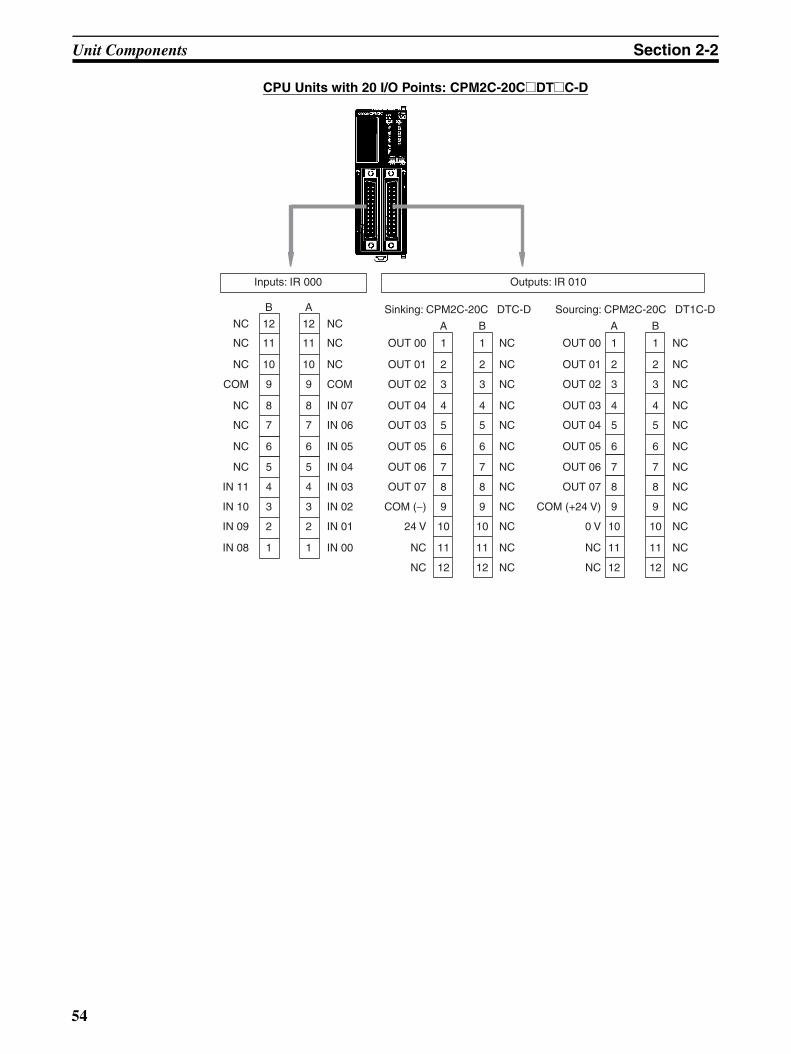
Unit Components Section 2-2
CPU Units with 20 I/O Points: CPM2C-20C@DT@C-D
Sinking: CPM2C-20C DTC-D Sourcing: CPM2C-20C DT1C-D
Inputs: IR 000 Outputs: IR 010
12
11
10
9
8
NC
NC
NC
COM
NC
NC
NC
NC
7
6
5
4
3
2
1
IN 11
IN 10
IN 09
IN 08
12
11
10
9
8
NC
NC
NC
COM
IN 07
IN 06
IN 05
IN 04
IN 03
IN 02
IN 01
IN 00
7
6
5
4
3
2
1
B A
1
2
3
4
5
6
7
8
9
10
11
12
OUT 00
OUT 01
OUT 02
OUT 04
OUT 03
OUT 05
OUT 06
OUT 07
COM (−)
24 V
NC
NC
A B
1
2
3
4
5
6
7
8
9
10
11
12
NC
NC
NC
NC
NC
NC
NC
NC
NC
NC
NC
NC
1
2
3
4
5
6
7
8
9
10
11
12
OUT 00
OUT 01
OUT 02
OUT 03
OUT 04
OUT 05
OUT 06
OUT 07
COM (+24 V)
0 V
NC
NC
A B
1
2
3
4
5
6
7
8
9
10
11
12
NC
NC
NC
NC
NC
NC
NC
NC
NC
NC
NC
NC
54
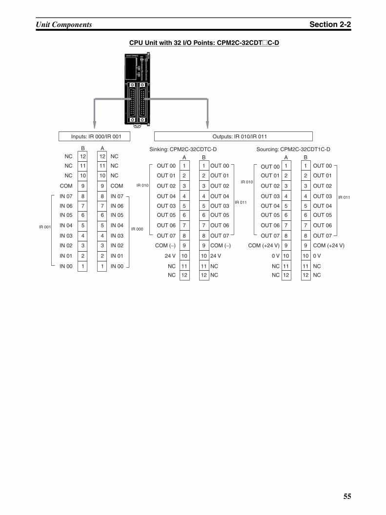
Unit Components Section 2-2
CPU Unit with 32 I/O Points: CPM2C-32CDT@C-D
Inputs: IR 000/IR 001 Outputs: IR 010/IR 011
Sinking: CPM2C-32CDTC-D Sourcing: CPM2C-32CDT1C-D12
11
10
9
8
NC
NC
NC
COM
IN 07
IN 06
IN 05
IN 04
IN 03
IN 02
IN 01
IN 00
7
6
5
4
3
2
1
12
11
10
9
8
NC
NC
NC
COM
IN 07
IN 06
IN 05
IN 04
IN 03
IN 02
IN 01
IN 00
7
6
5
4
3
2
1
B A
1
2
3
4
5
6
7
8
9
10
11
12
OUT 00
OUT 01
OUT 02
OUT 04
OUT 03
OUT 05
OUT 06
OUT 07
COM (−)
24 V
NC
NC
A B
1
2
3
4
5
6
7
8
9
10
11
12
1
2
3
4
5
6
7
8
9
10
11
12
OUT 00
OUT 01
OUT 02
OUT 03
OUT 04
OUT 05
OUT 06
OUT 07
COM (+24 V)
0 V
NC
NC
A B
1
2
3
4
5
6
7
8
9
10
11
12
IR 001 IR 000
IR 010
IR 011
OUT 00
OUT 01
OUT 02
OUT 04
OUT 03
OUT 05
OUT 06
OUT 07
COM (−)
24 V
NC
NC
IR 010
IR 011
OUT 00
OUT 01
OUT 02
OUT 03
OUT 04
OUT 05
OUT 06
OUT 07
COM (+24 V)
0 V
NC
NC
55
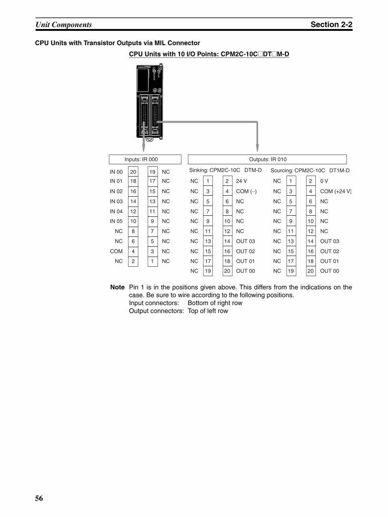
Unit Components Section 2-2
CPU Units with Transistor Outputs via MIL Connector
CPU Units with 10 I/O Points: CPM2C-10C@DT@M-D
Note Pin 1 is in the positions given above. This differs from the indications on thecase. Be sure to wire according to the following positions.Input connectors: Bottom of right rowOutput connectors: Top of left row
Inputs: IR 000 Outputs: IR 010
Sinking: CPM2C-10C DTM-D Sourcing: CPM2C-10C DT1M-D20
18
16
14
12
10
8
6
4
2
IN 00
IN 01
IN 02
IN 03
IN 04
IN 05
NC
NC
COM
NC
19
17
15
13
11
9
7
5
3
1
1
3
5
7
9
11
13
15
17
19
2
4
6
8
10
12
14
16
18
20
24 V
COM (−)
NC
NC
NC
NC
OUT 03
OUT 02
OUT 01
OUT 00
NC
NC
NC
NC
NC
NC
NC
NC
NC
NC
NC
NC
NC
NC
NC
NC
NC
NC
NC
NC
1
3
5
7
9
11
13
15
17
19
2
4
6
8
10
12
14
16
18
20
0 V
COM (+24 V)
NC
NC
NC
NC
OUT 03
OUT 02
OUT 01
OUT 00
NC
NC
NC
NC
NC
NC
NC
NC
NC
NC
56

Unit Components Section 2-2
CPU Units with 20 I/O Points: CPM2C-20C@DT@M-D
Note Pin 1 is in the positions given above. This differs from the indications on thecase. Be sure to wire according to the following positions.Input connectors: Bottom of right rowOutput connectors: Top of left row
Sinking: CPM2C-20C DTM-D Sourcing: CPM2C-20C DT1M-D
Inputs: IR 000 Outputs: IR 010
20
18
16
14
12
10
8
6
4
2
IN 00
IN 01
IN 02
IN 03
IN 04
IN 05
IN 06
IN 07
COM
NC
19
17
15
13
11
9
7
5
3
1
1
3
5
7
9
11
13
15
17
19
2
4
6
8
10
12
14
16
18
20
24 V
COM (−)
OUT 07
OUT 06
OUT 05
OUT 04
OUT 03
OUT 02
OUT 01
OUT 00
IN 08
IN 09
IN 10
IN 11
NC
NC
NC
NC
COM
NC
NC
NC
NC
NC
NC
NC
NC
NC
NC
NC
1
3
5
7
9
11
13
15
17
19
2
4
6
8
10
12
14
16
18
20
0 V
COM (+24 V)
OUT 07
OUT 06
OUT 05
OUT 04
OUT 03
OUT 02
OUT 01
OUT 00
NC
NC
NC
NC
NC
NC
NC
NC
NC
NC
57
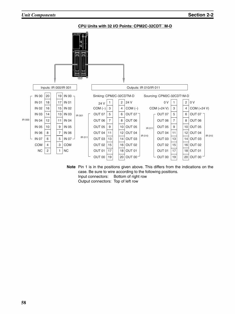
Unit Components Section 2-2
CPU Units with 32 I/O Points: CPM2C-32CDT@M-D
Note Pin 1 is in the positions given above. This differs from the indications on thecase. Be sure to wire according to the following positions.Input connectors: Bottom of right rowOutput connectors: Top of left row
Sinking: CPM2C-32CDTM-D Sourcing: CPM2C-32CDT1M-D
Inputs: IR 000/IR 001 Outputs: IR 010/IR 011
20
18
16
14
12
10
8
6
4
2
IN 00
IN 01
IN 02
IN 03
IN 04
IN 05
IN 06
IN 07
COM
NC
19
17
15
13
11
9
7
5
3
1
1
3
5
7
9
11
13
15
17
19
24 V
COM (−)
OUT 07
OUT 06
OUT 05
OUT 04
OUT 03
OUT 02
OUT 01
OUT 00
2
4
6
8
10
12
14
16
18
20
IR 000
IR 001
IR 011IR 010
IR 011
IN 00
IN 01
IN 02
IN 03
IN 04
IN 05
IN 06
IN 07
COM
NC
24 V
COM (−)
OUT 07
OUT 06
OUT 05
OUT 04
OUT 03
OUT 02
OUT 01
OUT 00
1
3
5
7
9
11
13
15
17
19
0 V
COM (+24 V)
OUT 07
OUT 06
OUT 05
OUT 04
OUT 03
OUT 02
OUT 01
OUT 00
2
4
6
8
10
12
14
16
18
20
IR 010
0 V
COM (+24 V)
OUT 07
OUT 06
OUT 05
OUT 04
OUT 03
OUT 02
OUT 01
OUT 00
58
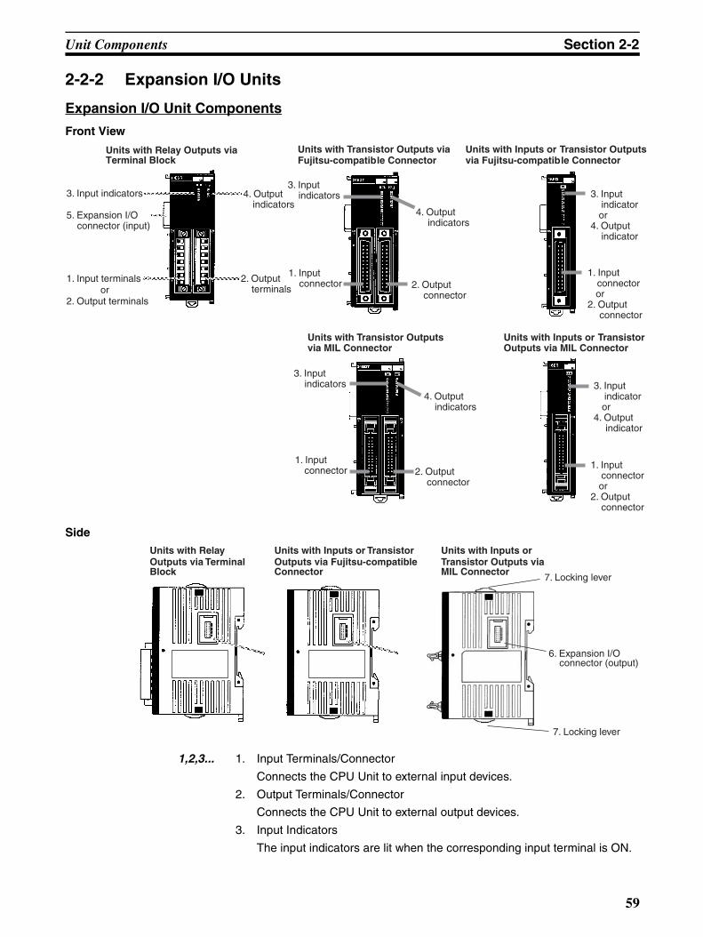
Unit Components Section 2-2
2-2-2 Expansion I/O Units
Expansion I/O Unit Components
Front View
Side
1,2,3... 1. Input Terminals/Connector
Connects the CPU Unit to external input devices.
2. Output Terminals/Connector
Connects the CPU Unit to external output devices.
3. Input Indicators
The input indicators are lit when the corresponding input terminal is ON.
1. Input terminals
3. Input indicators 4. Outputindicators
2. Output terminals
5. Expansion I/O connector (input)
or2. Output terminals
1. Input connector
3. Input indicators
Units with Transistor Outputs via Fujitsu-compatible Connector
Units with Inputs or Transistor Outputs via Fujitsu-compatible Connector
4. Output indicators
2. Output connector
1. Input connector
or 2. Output
connector
3. Input indicator
or 4. Output
indicator
1. Input connector
3. Input indicators
Units with Transistor Outputs via MIL Connector
Units with Inputs or Transistor Outputs via MIL Connector
4. Output indicators
2. Output connector
1. Input connector
or 2. Output
connector
3. Input indicator
or 4. Output
indicator
Units with Relay Outputs via Terminal Block
Units with Relay Outputs via Terminal Block
6. Expansion I/O connector (output)
7. Locking lever
7. Locking lever
Units with Inputs or Transistor Outputs via Fujitsu-compatible Connector
Units with Inputs or Transistor Outputs via MIL Connector
59
Unit Components Section 2-2
Note Input indicators will reflect the status of the corresponding inputseven when the PC is stopped, but the corresponding input bits willnot be refreshed.
4. Output Indicators
The output indicators are lit when the corresponding output terminal is ON.
5. Expansion I/O Connector (Input)
Connects the Expansion I/O Unit to the CPU Unit or the previous Expan-sion Unit or Expansion I/O Unit.
Note The indicators are lit during I/O refreshing. The status of an outputindicator will also reflect the status of the corresponding output whenthe output is being used as a pulse output.
6. Expansion I/O Connector (Output)
Connects the Expansion I/O Unit to the next Expansion I/O Unit or Expan-sion Unit, if necessary. Up to 5 Expansion I/O Units and Expansion Unitscan be connected to a CPU Unit. Only 10 words, however, can be allocatedfor input and output.
A cover for the expansion I/O connector is not included with the ExpansionI/O Unit. Use the cover included with the CPU Unit to cover the unused ex-pansion I/O connector on the last Expansion I/O Unit or Expansion Unit inthe PC.
7. Locking Lever
Used for securing Expansion I/O Units.
60

Unit Components Section 2-2
I/O Terminal and Connector Pin Allocation
Expansion I/O Units with Relay Outputs via Terminal Block
Outputs: IR word n
Inputs: IR word m Outputs: IR word n
Shared common
COM
IN 04
IN 03
IN 02
IN 01
IN 00
7
6
5
4
3
2
1
1
2
3
4
5
6
7 COM
IN 05
OUT 03
OUT 02
OUT 01
OUT 00
COM
COM
10 I/O Points: CPM2C-10EDR 20 I/O Points: CPM2C-20EDR
Inputs: IR word m Outputs: IR word n
Shared common
Shared common
Shared common
Shared common8 Output Points: CPM2C-8ER
Shared common
Shared common
COM
OUT 03
OUT 02
COM
OUT 01
COM
OUT 00
OUT 04
COM
OUT 05
COM
OUT 06
OUT 07
COM
1
2
3
4
5
6
71
2
3
4
5
6
7
13
12
11
10
9
8
7
6
5
4
3
2
1
1
2
3
4
5
6
7
8
9
10
11
12
13
COM
IN 11
IN 10
IN 09
IN 08
IN 07
IN 06
IN 05
IN 04
IN 03
IN 02
IN 01
IN 00
OUT 00
OUT 01
COM
OUT 02
OUT 03
COM
OUT 04
OUT 05
COM
OUT 06
OUT 07
COM
COM
61

Unit Components Section 2-2
Expansion I/O Units with Transistor Outputs via Fujitsu-compatible Connector
Inputs: IR word m Outputs: IR word n
24 I/O Points: CPM2C-24EDT@C
Sinking: CPM2C-24EDTC Sourcing: CPM2C-24EDT1C12
11
10
9
8
NC
NC
NC
COM
IN 15
IN 14
IN 13
IN 12
IN 11
IN 10
IN 9
IN 8
7
6
5
4
3
2
1
12
11
10
9
8
NC
NC
NC
COM
IN 07
IN 06
IN 05
IN 04
IN 03
IN 02
IN 01
IN 00
7
6
5
4
3
2
1
B A
1
2
3
4
5
6
7
8
9
10
11
12
OUT 00
OUT 01
OUT 02
OUT 04
OUT 03
OUT 05
OUT 06
OUT 07
COM (−)
24 V
NC
NC
A B
1
2
3
4
5
6
7
8
9
10
11
12
NC
NC
NC
NC
NC
NC
NC
NC
NC
NC
NC
NC
1
2
3
4
5
6
7
8
9
10
11
12
OUT 00
OUT 01
OUT 02
OUT 03
OUT 04
OUT 05
OUT 06
OUT 07
COM (+24 V)
0 V
NC
NC
A B
1
2
3
4
5
6
7
8
9
10
11
12
NC
NC
NC
NC
NC
NC
NC
NC
NC
NC
NC
NC
62

Unit Components Section 2-2
32 I/O Points: CPM2C-32EDT@C
Sinking: CPM2C-32EDTC Sourcing: CPM2C-32EDT1C
Inputs: IR word m Outputs: IR word n
12
11
10
9
8
NC
NC
NC
COM
IN 15
IN 14
IN 13
IN 12
IN 11
IN 10
IN 9
IN 8
7
6
5
4
3
2
1
12
11
10
9
8
NC
NC
NC
COM
IN 07
IN 06
IN 05
IN 04
IN 03
IN 02
IN 01
IN 00
7
6
5
4
3
2
1
B A
1
2
3
4
5
6
7
8
9
10
11
12
OUT 00
OUT 01
OUT 02
OUT 04
OUT 03
OUT 05
OUT 06
OUT 07
COM (−)
24 V
NC
NC
A B
1
2
3
4
5
6
7
8
9
10
11
12
OUT 08
OUT 09
OUT 10
OUT 11
OUT 12
OUT 13
OUT 14
OUT 15
COM (−)
24 V
NC
NC
1
2
3
4
5
6
7
8
9
10
11
12
OUT 00
OUT 01
OUT 02
OUT 03
OUT 04
OUT 05
OUT 06
OUT 07
COM (+24 V)
0 V
NC
NC
A B
1
2
3
4
5
6
7
8
9
10
11
12
OUT 08
OUT 09
OUT 10
OUT 11
OUT 12
OUT 13
OUT 14
OUT 15
COM (+24 V)
0 V
NC
NC
63

Unit Components Section 2-2
Inputs: IR word m
NC
NC
NC
NC
NC
NC
COM
IN 07
IN 06
IN 05
IN 04
IN 03
IN 02
IN 01
IN 00
B A
1
2
3
4
5
6
7
8
9
10
11
12
1
2
3
4
5
6
7
8
9
10
11
12
COM
IN 15
IN 14
IN 13
IN 12
IN 11
IN 10
IN 09
IN 08
16 Input Points: CPM2C-16EDC8 Input Points: CPM2C-8EDC
Inputs: IR word m
NC
NC
NC
NC
NC
NC
NC
NC
NC
NC
NC
NC
NC
NC
NC
COM
IN 07
IN 06
IN 05
IN 04
IN 03
IN 02
IN 01
IN 00
B A
1
2
3
4
5
6
7
8
9
10
11
12
1
2
3
4
5
6
7
8
9
10
11
12
Outputs: IR word n
COM ( )
A1
2
3
4
5
6
7
8
9
10
11
12
B1
2
3
4
5
6
7
8
9
10
11
12
A1
2
3
4
5
6
7
8
9
10
11
12
B1
2
3
4
5
6
7
8
9
10
11
12
NC
NC
NC
NC
NC
NC
NC
NC
NC
NC
NC
NC
NC
NC
0 V
COM (+24 V)
OUT 07
OUT 06
OUT 05
OUT 04
OUT 03
OUT 02
OUT 01
OUT 00NC
NC
NC
NC
NC
NC
NC
NC
NC
NC
NC
NC
NC
NC
24 V
OUT 07
OUT 06
OUT 05
OUT 04
OUT 03
OUT 02
OUT 01
OUT 00
Sinking: CPM2C-8ETC Sourcing: CPM2C-8ET1C
8 Output Points: CPM2C-8ET@C
64

Unit Components Section 2-2
Outputs: IR word n
Sinking: CPM2C-16ETC Sourcing: CPM2C-16ET1C
COM (−)
A
1
2
3
4
5
6
7
8
9
10
11
12
B
1
2
3
4
5
6
7
8
9
10
11
12
A
1
2
3
4
5
6
7
8
9
10
11
12
B
1
2
3
4
5
6
7
8
9
10
11
12
NC
NC
0 V
COM (+24 V)
OUT 07
OUT 06
OUT 05
OUT 04
OUT 03
OUT 02
OUT 01
OUT 00
NC
NC
NC
NC
24 V
OUT 07
OUT 06
OUT 05
OUT 04
OUT 03
OUT 02
OUT 01
OUT 00
24 V
COM (−)
OUT 15
OUT 14
OUT 13
OUT 12
OUT 11
OUT 10
OUT 09
OUT 08
NC
NC
OUT 15
OUT 14
OUT 13
OUT 12
OUT 11
OUT 10
OUT 09
OUT 08
0 V
COM (+24 V)
16 Output Points: CPM2C-16ET@C
65
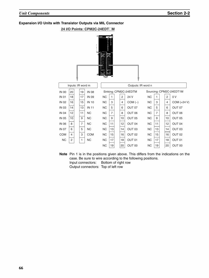
Unit Components Section 2-2
Expansion I/O Units with Transistor Outputs via MIL Connector
Note Pin 1 is in the positions given above. This differs from the indications on thecase. Be sure to wire according to the following positions.Input connectors: Bottom of right rowOutput connectors: Top of left row
Inputs: IR word m Outputs: IR word n
24 I/O Points: CPM2C-24EDT@M
Sinking: CPM2C-24EDTM Sourcing: CPM2C-24EDT1M20
18
16
14
12
10
8
6
4
2
IN 00
IN 01
IN 02
IN 03
IN 04
IN 05
IN 06
IN 07
COM
NC
19
17
15
13
11
9
7
5
3
1
1
3
5
7
9
11
13
15
17
19
2
4
6
8
10
12
14
16
18
20
24 V
COM (−)
OUT 07
OUT 06
OUT 05
OUT 04
OUT 03
OUT 02
OUT 01
OUT 00
IN 08
IN 09
IN 10
IN 11
NC
NC
NC
NC
COM
NC
NC
NC
NC
NC
NC
NC
NC
NC
NC
NC
1
3
5
7
9
11
13
15
17
19
2
4
6
8
10
12
14
16
18
20
0 V
COM (+24 V)
OUT 07
OUT 06
OUT 05
OUT 04
OUT 03
OUT 02
OUT 01
OUT 00
NC
NC
NC
NC
NC
NC
NC
NC
NC
NC
66

Unit Components Section 2-2
Note Pin 1 is in the positions given above. This differs from the indications on thecase. Be sure to wire according to the following positions.Input connectors: Bottom of right rowOutput connectors: Top of left row
Inputs: IR word m Outputs: IR word n
32 I/O Points: CPM2C-32EDT@M
Sinking: CPM2C-32EDTM Sourcing: CPM2C-32EDT1M20
18
16
14
12
10
8
6
4
2
IN 00
IN 01
IN 02
IN 03
IN 04
IN 05
IN 06
IN 07
COM
NC
19
17
15
13
11
9
7
5
3
1
1
3
5
7
9
11
13
15
17
19
24 V
COM (−)
OUT 15
OUT 14
OUT 13
OUT 12
OUT 11
OUT 10
OUT 09
OUT 08
2
4
6
8
10
12
14
16
18
20
IN 08
IN 09
IN 10
IN 11
IN 12
IN 13
IN 14
IN 15
COM
NC
24 V
COM (−)
OUT 07
OUT 06
OUT 05
OUT 04
OUT 03
OUT 02
OUT 01
OUT 00
1
3
5
7
9
11
13
15
17
19
0 V
COM (+24 V)
OUT 15
OUT 14
OUT 13
OUT 12
OUT 11
OUT 10
OUT 09
OUT 08
2
4
6
8
10
12
14
16
18
20
0 V
COM (+24 V)
OUT 07
OUT 06
OUT 05
OUT 04
OUT 03
OUT 02
OUT 01
OUT 00
67

Unit Components Section 2-2
16 Input Points: CPM2C-16EDM8 Input Points: CPM2C-8EDM
Sinking: CPM2C-8ETM Sourcing: CPM2C-8ET1M
8 Output Points: CPM2C-8ET@M
Inputs: IR word m
20
18
16
14
12
10
8
6
4
2
IN 00
IN 01
IN 02
IN 03
IN 04
IN 05
IN 06
IN 07
COM
NC
19
17
15
13
11
9
7
5
3
1
NC
NC
NC
NC
NC
NC
NC
NC
NC
NC
IN 08
IN 09
IN 10
IN 11
IN 12
IN 13
IN 14
IN 15
COM
NC
Inputs: IR word m
20
18
16
14
12
10
8
6
4
2
IN 00
IN 01
IN 02
IN 03
IN 04
IN 05
IN 06
IN 07
COM
NC
19
17
15
13
11
9
7
5
3
1
Outputs: IR word n
1
3
5
7
9
11
13
15
17
19
2
4
6
8
10
12
14
16
18
20
24 V
COM (−)
OUT 07
OUT 06
OUT 05
OUT 04
OUT 03
OUT 02
OUT 01
OUT 00
1
3
5
7
9
11
13
15
17
19
2
4
6
8
10
12
14
16
18
20
0 V
COM (+24 V)
OUT 07
OUT 06
OUT 05
OUT 04
OUT 03
OUT 02
OUT 01
OUT 00
NC
NC
NC
NC
NC
NC
NC
NC
NC
NC
NC
NC
NC
NC
NC
NC
NC
NC
NC
NC
8ED16ED
68

Unit Components Section 2-2
2-2-3 CPM2C-MAD11 Analog I/O Unit
1,2,3... 1. Analog I/O Terminals
Connect the CPU Unit to analog input and analog output devices.
Sinking: CPM2C-16ETM Sourcing: CPM2C-16ET1M
16 Output Points: CPM2C-16ET@M
Outputs: IR word n
1
3
5
7
9
11
13
15
17
19
2
4
6
8
10
12
14
16
18
20
24 V
COM (−)
OUT 07
OUT 06
OUT 05
OUT 04
OUT 03
OUT 02
OUT 01
OUT 00
1
3
5
7
9
11
13
15
17
19
2
4
6
8
10
12
14
16
18
20
0 V
COM (+24 V)
OUT 07
OUT 06
OUT 05
OUT 04
OUT 03
OUT 02
OUT 01
OUT 00
0 V
COM (+24 V)
OUT 15
OUT 14
OUT 13
OUT 12
OUT 11
OUT 10
OUT 09
OUT 08
24 V
COM (−)
OUT 15
OUT 14
OUT 13
OUT 12
OUT 11
OUT 10
OUT 09
OUT 08
Front View Right Side
3. Expansion I/O connector (input)
2. DIP switch
1. Analog I/O terminals
5. Locking lever
4. Expansion I/O connector (output)
5. Locking lever
69

Unit Components Section 2-2
2. DIP SwitchUsed to switch between voltage and current input, and to perform averageprocessing.
3. Expansion I/O Connector (Input)Connects the Analog I/O Unit to the CPU Unit or previous Expansion Unitor Expansion I/O Unit.
4. Expansion I/O Connector (Output)Connects the Analog I/O Unit to the next Expansion I/O Unit or ExpansionUnit, if necessary. Up to 5 Expansion I/O Units and Expansion Units canbe connected to a CPU Unit. Only 10 words, however, can be allocated forinput and output respectively.A cover for the expansion I/O connector is not included with the ExpansionUnit. Use the cover included with the CPU Unit to cover the unused expan-sion I/O connector on the last Expansion I/O Unit or Expansion Unit in thePC.
5. Locking LeverUsed for securing Expansion Units.
2-2-4 CPM2C-TS001/TS101 Temperature Sensor Units
Average processing for analog input 0(OFF: Average processing not performed; ON: Average processing performed)Average processing for analog input 1(OFF: Average processing not performed; ON: Average processing performed)Input type for analog input 0(OFF: Voltage input; ON: Current input)Input type for analog input 1(OFF: Voltage input; ON: Current input)
ON
12
34
Front View Right Side
1. Temperature input terminals
3. Rotary switch
2. DIP switch
Cold junction compensator
4. Expansion I/O connector (input)
CPM2C-TS001
1. Temperature input terminals
3. Rotary switch
2. DIP switch
4. Expansion I/O connector (input)
CPM2C-TS101
6. Locking lever
6. Locking lever
5. Expansion I/O connector (output)
70

Unit Components Section 2-2
1,2,3... 1. Temperature Input Terminals
Connect to a thermocouple or a platinum resistance thermometer.
2. DIP Switch
Sets the temperature unit (°C or °F) and the number of decimal placesused.
3. Rotary Switch
Sets the temperature range.
CPM2C-TS001
CPM2C-TS101
4. Expansion I/O Connector (Input)
Connects the Temperature Sensor Unit to the CPU Unit or the previous Ex-pansion I/O Unit or Expansion Unit.
5. Expansion I/O Connector (Output)
Connects the Temperature Sensor Unit to the next Expansion I/O Unit orExpansion Unit, if necessary. Up to 5 Expansion I/O Units and ExpansionUnits can be connected to a CPU Unit. Only 10 words, however, can beallocated for input and output.
A cover for the expansion I/O connector is not included with the ExpansionUnit. Use the cover included with the CPU Unit to cover the unused expan-sion I/O connector on the last Expansion I/O Unit or Expansion Unit in thePC.
6. Locking Lever
Used for securing Expansion Units.
Set value Thermocouple Range (°C) Range (°F)
0 K –200 to 1,300 –300 to 2,300
1 0.0 to 500.0 0.0 to 900.0
2 J –100 to 850 –100 to 1,500
3 0.0 to 400.0 0.0 to 750.0
4 to F --- Setting not possible
Set value Platinum resistance
thermometer
Range (°C) Range (°F)
0 Pt100 –200.0 to 650.0 –300.0 to 1,200.0
1 JPt100 –200.0 to 650.0 –300.0 to 1,200.0
2 to F --- Setting not possible
Temperature unit for temperature input 0OFF: C; ON: FNumber of decimal places usedOFF: Normal (0 or 1); ON: 2
71

Unit Components Section 2-2
2-2-5 CPM2C-SRT21 CompoBus/S I/O Link Unit
1,2,3... 1. CompoBus/S Terminals
Include the CompoBus/S communications data high/low terminal, and NCterminals. Power is supplied to the Unit internally.
2. DIP Switch
The DIP switch sets the Unit’s node address, sets the communicationsmode, and determines whether or not the outputs will be cleared in theevent of a communications error.
Note The Long-distance Communications Mode can be used only when connectedto one of the following Master Units: C200HW-SRM21-V1, CQM1-SRM21-V1,SRM1-C0@-V2, or CPM2C-S.
3. LED Indicators
These indicators show the status of CompoBus/S communications.
4. Expansion I/O Connector (Input)
Connects the CompoBus/S I/O Link Unit to the CPU Unit or the previousExpansion I/O Unit or Expansion Unit.
5. Expansion I/O Connector (Output)
Connects the CompoBus/S I/O Link Unit to the next Expansion I/O Unit orExpansion Unit, if necessary. Up to 5 Expansion I/O Units and Expansion
Front View Right Side
1. CompoBus/S terminals
2. DIP switch
4. Expansion I/O connector (input)
3. LED indicators
6. Locking lever
6. Locking lever
5. Expansion I/O connector (output)
Pin(s) Function
1 to 4 (labeled 1, 2, 4, and 8)
These pins set the Unit’s node address using the DIP switch pins as binary digits. (1 = ON)0: 0000 1: 0001 2: 0010 3: 00114: 0100 5: 0101 6: 0110 7: 01118: 1000 9: 1001 10: 1010 11: 101112: 1100 13: 1101 14: 1110 15: 1111
DR ON: Long-distance Communications ModeOFF: High-speed Communications Mode(See note.)
HOLD ON: Retain inputs when a communications error occurs.OFF: Clear inputs when a communications error occurs.
Indicator Status Meaning
COMM(yellow)
ON Communications in progress.
OFF Communications error or stopped.
ERR(red)
ON A communications error has occurred.
OFF Indicates normal or no communications.
72

Unit Components Section 2-2
Units can be connected to a CPU Unit. Only 10 words, however, can beallocated for input and output respectively.
A cover for the expansion I/O connector is not included with the ExpansionUnit. Use the cover included with the CPU Unit to cover the unused expan-sion I/O connector on the last Expansion I/O Unit or Expansion Unit in thePC.
6. Locking Lever
Used for securing Expansion Units.
2-2-6 CPM2C-CIF21 Simple Communications Unit
Note The CPM2C-CIF21 can be used only with the CPM2C.
Front Side
1. RS-422/RS-485 port
4. RS-422/RS-485 switch (SW1)
6. DM area setting switch
2. RS-232C port
8. Connector
7. Status indicators5. Communications switch (SW3)
Cover
3. Terminating resistance switches (SW4)
Top Use a flat-blade screwdriver or similar device if the cover is difficult to remove.
73

Unit Components Section 2-2
1,2,3... 1. RS-422/RS-485 Port
Connects CompoWay/F general-purpose communications componentsand SYSWAY Temperature Controllers and Digital Panel Meters.
Note Confirm polarity before connecting RS-422/485 lines. Some devices requirethat SDA/SDB or RDA/RDB and the +/– signal be reversed.
2. RS-232C Port
Connects to an RS-232C interface on a computer, PT (Programmable Ter-minal), etc.
3. Terminating Resistance Switches (SW4)
Turn ON both SW4-1 and SW4-2 on both ends of the RS-422/RS-485transmission path. These switches are set to OFF at the factory.
RS-422 Pin Assignments
Receive data (input)
Transmit data (output)
RS-485 Pin Assignments
Transmit/receive data (I/O)
Transmit/receive data (I/O)
Max. line length: 500 m Max. line length: 500 m
RS-422 Connection Example RS-485 Connection Example
CPM2C-CIF21Communications component CPM2C-CIF21
Communications component
RDA−
RDB+
SDA−
SDB+
NC
RDA−
RDB+
SDA−
SDB+
NC
SDA−
SDB+
RDA−
RDB+ SDB+
SDA−
RDB+
RDA− SDA−
SDB+
RDA−
RDB+
RDB+
RDA−
Top port Signal conversion
Changes levels between CMOS (CPU Unit) and RS-422 (general-purpose communications components).RS-422 (general-purpose communications compo-nents) insulated using DC/DC converter or photocou-pler.
Function Conversion between CPU Unit and Host Link
General-purpose communications components are CompoWay/F or SYSWAY components, which support general-purpose serial communications.
Bottom port Signal conversion
Outputs the RS-232C interface directly from the CPU Unit.
Function Host Link, no-protocol, 1:1 link, or 1:1 NT Link
Pin Assignments
9 SG8 NC7 NC6 NC
5 CTS4 RTS3 RxD2 TxD1 NC
74

Unit Components Section 2-2
4. RS-422/RS-485 Switch (SW1)
Switches the RS-485 interface and sets RS/CS controls for the RS-485 in-terface.
Note The default setting is for 2-wire RS-485 communications. Do not turn ON bothSW1-3 and SW1-4 at the same time. Doing so will destroy internal circuits.
5. Communications Switch (SW3)
Note a) Pins 3 to 6 on SW3 are used to set communications between gen-eral-purpose communications components and the Simple Com-munications Unit.
b) Turn OFF pin 7 on SW3. Operation may not be correct if this pin isturned ON.
Pin on SW1 RS-422 RS-485
1 OFF ON
2 OFF ON
3 ON OFF
4 OFF ON
Resistance connected
Resistance not connected
SW4Terminating ResistanceRS-422: 235 Ω (combined resistance must be 110 Ω min)RS-485: 118 Ω (combined resistance must be 54 Ω min)
ON
12
34
ON
12
34
SW1 SW1
RS-422 Setting RS-485 Setting
Pin Setting OFF ON
1 Baud rate with CPU Unit 9,600 bps 19,200 bps
2 Baud rate with components Normal 9,600 bps 19,200 bps
High-speed 38,400 bps 57,600 bps
3 Data length with components 7 bits 8 bits
4 Parity 1 setting with components Yes None
5 Parity 2 setting with components Even Odd
6 Stop bits with components 2 1
7 Not used. (Always leave pin 7 OFF.) Leave OFF. ---
8 Component communications speed Normal High-speed
ON
12
34
All pins are turned OFF at the factory.
SW3
56
78
75

Unit Components Section 2-2
6. DM Area Setting Switch (SW2)
Sets the starting word in the DM Area
7. Status Indicators
Indicate the operating status of the Simple Communications Unit.
Setting Starting word in DM Area
0 DM 0000
1 DM 0100
2 DM 0200
3 DM 0300
4 DM 0400
5 DM 0500
6 DM 0600
7 DM 0700
8 DM 0800
9 DM 0900
A DM 1000
B DM 1100
C DM 1200
D DM 1300
E DM 1400
F DM 1500
Label Status Meaning
RUN Lit Communications established between Simple Communica-tions Unit and CPU Unit. Simple Communications Unit oper-ating.
Not lit Simple Communications Unit not operating.
Flashing Communications between Simple Communications Unit and CPU Unit either not established or interrupted.
ERR/ALM Lit Fatal error occurred. (Unit operation stops.)
Flashing Non-fatal error occurred. (Unit operation continues.)
Not lit Unit operating normally.
COMM1 Flashing Transferring data between Simple Communications Unit and CPU Unit
Not lit Not transferring data
COMM2 Flashing Transferring data between Simple Communications Unit and connected components
Not lit Not transferring data
76

Unit Components Section 2-2
8. Connector
Connects to CPU Unit communications port.
2-2-7 CPM2C-CIF01-V1 Peripheral/RS-232C Adapter Unit
1,2,3... 1. Peripheral Port
Used to connect to Programming Devices (including Programming Con-soles), host computers, or general-purpose external devices. Use a spe-cial connecting cable (CS1W-CN114, CS1W-CN118) for connections. With the CPM2C-CIF01-V1, the cable switch (SW1) can be turned ON toenable connecting to a personal computer with a CS1W-CN226/CN626Connecting Cable.
Note a) The C200H-PRO27-E Programming Console can be connecteddirectly to the CPM2C’s CPU Unit using a special connecting ca-ble (CS1W-CN224/624).
RS-422 Interface Block Diagram
TxD
SE
RxD
0 V
C5V5 V
5 VC5V
0 VC0V
C0V
C0V
SW4
C5V
C5V
C5V
SDB
SDASW4
SW1
1 2
RDB
RDASW14
3
5 V
Front View
1. Peripheral port
3. RS-232C port
4. Connector
Do not use the CPM2C-CIF01-V1 with any PC other than the CPM2C. Do not connect another CPM2C-CIF01-V1 or the CPM2C-CIF11 to the CPM2C-CIF01-V1. The CPM2C-CN111 can be connected to the CPM2C-CIF01, but the peripheral port and the RS-232C port of the CPM2C-CN111 cannot be used simultaneously. If an attempt to use these ports simultaneously is made, communications will not be performed properly, and this may result in malfunction of equipment.
*: The CPM2C-CIF01 does not have a cable switch (SW1).
2. Cable switch (SW1)
77

Unit Components Section 2-2
b) Use the CS1W-CN114 when using the port as a peripheral port.
c) Use the CS1W-CN118 when using the port as a RS-232C port.
2. Cable Switch (SW1, CPM2C-CIF01-V1 Only)
Turn ON SW1 to use a CS1W-CN226/CN626 Connecting Cable to connectto a personal computer. Turn OFF SW1 to use any other cable.
3. RS-232C Port
Used to connect to the RS-232C interface of a personal computer or Pro-grammable Terminal (operator interface).
4. Connector
Connects to the communications port on the CPU Unit.
SW1
ON
OFF
Peripheral port on CPM2C-CIF01-V1
Signal conversion
Outputs signals from the CPU Unit’s CMOS inter-face without conversion, or converts CMOS level (CPU Unit side) to RS-232C (connected device side).
Function Host Link, peripheral bus, no-protocol, or Program-ming Console connections.
RS-232C port on CPM2C-CIF01-V1
Signal conversion
Outputs signals from the CPU Unit’s CMOS inter-face without conversion.
Function Host Link, no-protocol, 1:1 Link, or 1:1 NT Link con-nections.
Connector Pin Allocation
Internal ConfigurationCPM2C-CIF01-V1 CPM2C CPU Unit
Peripheral port(CMOS/RS-232C)
RS-232C port(D-sub connector)
CMOS level RS-232C conversion
Peripheral port(CMOS level)
RS-232C port(RS-232C)
78

Unit Components Section 2-2
2-2-8 CPM2C-CIF11 RS-422/RS-232C Adapter Unit
Note Do not use the CPM2C-CIF11 with any PC other than the CPM2C.
1,2,3... 1. RS422/485 Port
Used to connect to host computers, or standard external devices.
Note The maximum line length is 500 m.
2. RS-232C Port
Used to connect to the RS-232C interface of a personal computer or Pro-grammable Terminal (operator interface).
Front View Right Side
1. RS-422/485 port
3. Terminating resistance switch
2. RS-232C port
5. Connector4. RS-485 interface switch
Terminal Arrangement
Receive data (input)
Send data (output)
RDA
RDB+
SDA
SDB+
NC
Connector Pin Arrangement
79

Unit Components Section 2-2
3. Terminating Resistance Switch
Set this switch to ON only for double-ended connection to a Host Link net-work. This switch is factory-set to OFF.
4. RS-485 Interface Switch
Used to switch to the RS-485 interface, and to enable or disable RS/CScontrol when performing RS-485 communications.
RS-422/485 Connection ExampleCPM2C-CIF11 B500-AL004
ShieldConnector hood
Internal ConfigurationCPM2C-CIF11 CPM2C CPU Unit
RS-422/485 port(terminal block)
RS-232C port(D-sub connector)
CMOS level →RS-422 conversion
Peripheral port(CMOS level)
RS-232C port(RS-232C)
RS-422/485 port on CPM2C-CIF11
Signal conversion
Converts CMOS level (CPU Unit side) to RS-422 (connected device side).RS-422 (externally connected device) insulated using DC/DC converter or photocoupler.
Function Host Link, peripheral bus, or no-protocol connec-tions.
RS-232C port on CPM2C-CIF11
Signal conversion
Outputs signals from the CPU Unit’s CMOS interface without conversion.
Function Host Link, no-protocol, 1:1 Link, or 1:1 NT Link con-nections.
SW1
ON
OFF
Terminating ResistanceRS-422: 235 Ω (combined resistance must be 110 Ω min)RS-485: 118 Ω (combined resistance must be 54 Ω min)
80
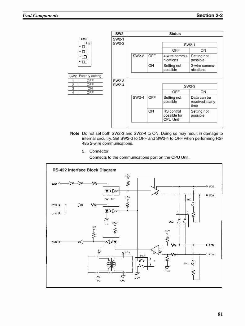
Unit Components Section 2-2
Note Do not set both SW2-3 and SW2-4 to ON. Doing so may result in damage tointernal circuitry. Set SW2-3 to OFF and SW2-4 to OFF when performing RS-485 2-wire communications.
5. Connector
Connects to the communications port on the CPU Unit.
SW2 Status
SW2-1SW2-2 SW2-1
OFF ON
SW2-2 OFF 4-wire commu-nications
Setting not possible
ON Setting not possible
2-wire commu-nications
SW2-3SW2-4 SW2-3
OFF ON
SW2-4 OFF Setting not possible
Data can be received at any time
ON RS control possible for CPU Unit
Setting not possible
Factory setting
OFFOFFONOFF
SW21234
RS-422 Interface Block Diagram
81

Unit Components Section 2-2
2-2-9 AC Power Supply Unit
1,2,3... 1. Terminal Block
Terminals for AC power supply input and service power supply (24 VDC).
2. LED Indicator
Lights when power is supplied.
3. CPU Unit Power Supply Connector
Use the connecting cable provided as an accessory to connect this con-nector to the power supply connector on the CPU Unit (24 VDC).
Note The ratings for the CPM2C-PA201 AC Power Supply Unit are 100 to240 VAC input; 24 VDC/600 mA output. The maximum current thatcan be supplied via the CPU Unit power supply connector and theservice power supply terminals on the terminal block is 600 mA.
Front View Bottom Side
1. Terminal block
2. LED indicator 3. CPU Unit power supply connector
82

SECTION 3Installation and Wiring
This section provides information on installing and wiring a CPM2C PC. Be sure to follow the directions and precautionsin this section when installing the CPM2C in a panel or cabinet, wiring the power supply, or wiring I/O.
3-1 Design Precautions . . . . . . . . . . . . . . . . . . . . . . . . . . . . . . . . . . . . . . . . . . . . . 84
3-1-1 Power Supply Wiring . . . . . . . . . . . . . . . . . . . . . . . . . . . . . . . . . . . . 84
3-1-2 Power Supply Voltage. . . . . . . . . . . . . . . . . . . . . . . . . . . . . . . . . . . . 84
3-1-3 Interlock and Limit Circuits . . . . . . . . . . . . . . . . . . . . . . . . . . . . . . . 84
3-2 Selecting an Installation Site. . . . . . . . . . . . . . . . . . . . . . . . . . . . . . . . . . . . . . 85
3-2-1 Installation Site Conditions. . . . . . . . . . . . . . . . . . . . . . . . . . . . . . . . 85
3-2-2 Panel/Cabinet Installation. . . . . . . . . . . . . . . . . . . . . . . . . . . . . . . . . 85
3-3 Installing the CPM2C . . . . . . . . . . . . . . . . . . . . . . . . . . . . . . . . . . . . . . . . . . . 86
3-3-1 Connecting Units . . . . . . . . . . . . . . . . . . . . . . . . . . . . . . . . . . . . . . . 87
3-3-2 CPM2C Installation . . . . . . . . . . . . . . . . . . . . . . . . . . . . . . . . . . . . . 88
3-4 Wiring and Connections . . . . . . . . . . . . . . . . . . . . . . . . . . . . . . . . . . . . . . . . . 89
3-4-1 General Precautions for Wiring . . . . . . . . . . . . . . . . . . . . . . . . . . . . 89
3-4-2 Power Supply Wiring . . . . . . . . . . . . . . . . . . . . . . . . . . . . . . . . . . . . 90
3-4-3 Using the AC Power Supply Unit . . . . . . . . . . . . . . . . . . . . . . . . . . . 91
3-4-4 Removing and Wiring I/O Terminal Blocks . . . . . . . . . . . . . . . . . . . 93
3-4-5 Removing and Wiring I/O Connectors . . . . . . . . . . . . . . . . . . . . . . . 94
3-4-6 Using I/O Terminals and Relay Terminals . . . . . . . . . . . . . . . . . . . . 100
3-4-7 Connecting Input Devices. . . . . . . . . . . . . . . . . . . . . . . . . . . . . . . . . 101
3-4-8 Connecting Output Devices . . . . . . . . . . . . . . . . . . . . . . . . . . . . . . . 116
3-4-9 RS-422 Port Connection . . . . . . . . . . . . . . . . . . . . . . . . . . . . . . . . . . 141
3-4-10 Programming Device Connections . . . . . . . . . . . . . . . . . . . . . . . . . . 142
3-4-11 No-Protocol Communications . . . . . . . . . . . . . . . . . . . . . . . . . . . . . 146
3-4-12 OMRON PT Connections . . . . . . . . . . . . . . . . . . . . . . . . . . . . . . . . . 147
3-4-13 One-to-one PC Link Connections. . . . . . . . . . . . . . . . . . . . . . . . . . . 148
3-4-14 CompoBus/S I/O Link Connections . . . . . . . . . . . . . . . . . . . . . . . . . 149
83

Design Precautions Section 3-1
3-1 Design PrecautionsObserve the following precautions when designing a system incorporating aCPM2C PC.
3-1-1 Power Supply WiringSeparate the power supply wiring from the control system, CPM2C system,and DC I/O system wiring. Separate the control circuits that supply power tothe main Unit from the main circuits using dedicated circuit protectors andfuses.
3-1-2 Power Supply Voltage
!Caution Use the power supply voltages indicated in SECTION 2 Unit Components andSpecifications. Failure to adhere to the specifications may result in fire.If the power supply voltage falls below 85% of the rated voltage, the CPM2Cwill stop and all outputs will be turned OFF. If low voltage affects the equip-ment, etc., provide a protection circuit which shuts OFF the output until thesupply voltage returns to the rated value.In places where power supply conditions are poor, take steps to ensure thatpower is supplied at the rated voltage. Be sure to adhere to safety precau-tions, such as providing breakers to prevent short circuits in external wiring.When conducting any of the following operations, turn OFF the power to thePC. Electrocution, product damage and malfunction may result.
• Connecting or disconnecting Expansion I/O Units, Expansion Units, andCPU Units.
• Assembling Units.• Connecting cables and wiring.• Connecting or disconnecting connectors.• Replacing the battery.
3-1-3 Interlock and Limit Circuits
!WARNING Emergency stop circuits, interlock circuits, limit circuits, and similar safetymeasures must be provided in external control circuits (i.e., not in the Pro-grammable Controller) to ensure safety in the system if an abnormality occursdue to malfunction of the PC or another external factor affecting the PC oper-ation. Not providing proper safety measures may result in serious accidents.
The following diagram shows an example of an interlock circuit.
In the interlock circuit above, MC1 and MC2 can’t be ON at the same timeeven if CPM2C outputs 01005 and 01006 are both ON (an incorrect PC oper-ation).
Interlock Circuit
Motor forward
Motor reverse
CPM2C
01005
01006
MC1
MC2
MC2
MC1
84
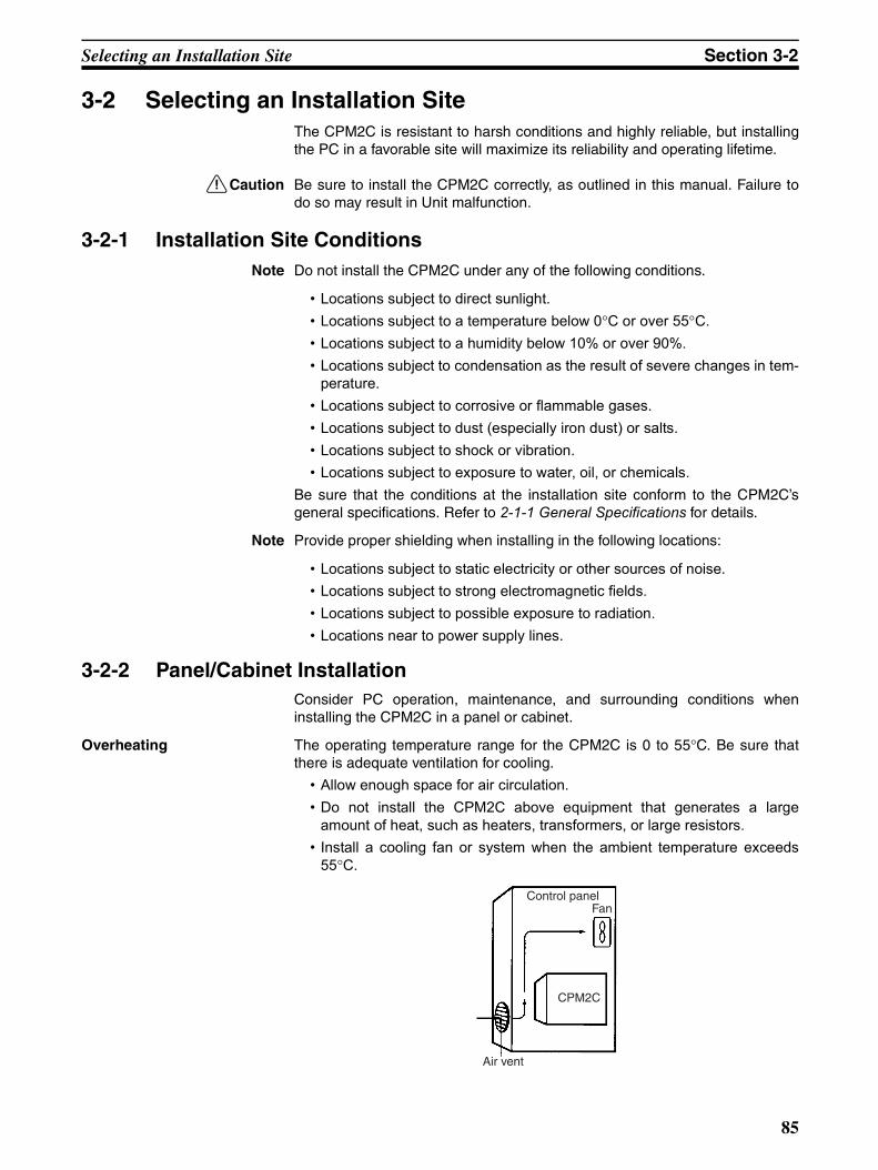
Selecting an Installation Site Section 3-2
3-2 Selecting an Installation SiteThe CPM2C is resistant to harsh conditions and highly reliable, but installingthe PC in a favorable site will maximize its reliability and operating lifetime.
!Caution Be sure to install the CPM2C correctly, as outlined in this manual. Failure todo so may result in Unit malfunction.
3-2-1 Installation Site ConditionsNote Do not install the CPM2C under any of the following conditions.
• Locations subject to direct sunlight.• Locations subject to a temperature below 0°C or over 55°C.• Locations subject to a humidity below 10% or over 90%.• Locations subject to condensation as the result of severe changes in tem-
perature.• Locations subject to corrosive or flammable gases.• Locations subject to dust (especially iron dust) or salts.• Locations subject to shock or vibration.• Locations subject to exposure to water, oil, or chemicals.
Be sure that the conditions at the installation site conform to the CPM2C’sgeneral specifications. Refer to 2-1-1 General Specifications for details.
Note Provide proper shielding when installing in the following locations:
• Locations subject to static electricity or other sources of noise.• Locations subject to strong electromagnetic fields.• Locations subject to possible exposure to radiation.• Locations near to power supply lines.
3-2-2 Panel/Cabinet InstallationConsider PC operation, maintenance, and surrounding conditions wheninstalling the CPM2C in a panel or cabinet.
Overheating The operating temperature range for the CPM2C is 0 to 55°C. Be sure thatthere is adequate ventilation for cooling.
• Allow enough space for air circulation.• Do not install the CPM2C above equipment that generates a large
amount of heat, such as heaters, transformers, or large resistors.• Install a cooling fan or system when the ambient temperature exceeds
55°C.
Control panelFan
Air vent
CPM2C
85

Installing the CPM2C Section 3-3
• Orient the CPM2C as shown below when installing it.
Electrical Noise Power lines and high-voltage equipment can cause electrical noise in the PC.• Do not install the CPM2C in a panel or cabinet with high-voltage equip-
ment.• Allow at least 200 mm between the CPM2C and nearby power lines.
Accessibility Ensure that the CPM2C can be accessed for normal operation and mainte-nance.
• Provide a clear path to the CPM2C for operation and maintenance. High-voltage equipment or power lines could be dangerous if they are in theway during routine operations.
• The PC will be easiest to access if the panel or cabinet is installed about 1to 1.6 m above the floor.
• Separate the CPM2C by at least 100 mm from other devices.
3-3 Installing the CPM2CThis section describes how to install the CPM2C and connect ExpansionUnits and Expansion I/O Units. Refer to Appendix B for diagrams showing thedimensions of the Units.
Top
Bottom
CPM2C
200 mm min.
200 mm min.
Other device
100 mm min.
Other device
100 mm min.
86

Installing the CPM2C Section 3-3
3-3-1 Connecting UnitsUp to 5 Expansion I/O Units and Expansion Units can be connected to aCPM2C CPU Unit. Use the following procedure when connecting an Expan-sion I/O Unit or Expansion Unit.
1,2,3... 1. Remove the cover from the CPU Unit’s or the last Expansion I/O Unit’s orExpansion Unit’s expansion I/O connector. If the cover is difficult to re-move, use a flat-blade screwdriver to pry the cover from the expansion I/Oconnector.
2. Align the Unit and CPU Unit (or previous Expansion I/O Unit or ExpansionUnit) so that the catches (top and bottom) on the connectors fit together.Press the Units together to connect them.
3. Lock the Units together by closing the locks (top and bottom) on the CPUUnit (or previous Expansion I/O Unit or Expansion Unit). Place the cover(included with the CPU Unit) on the last Unit’s expansion I/O connector.
Expansion I/O connector cover
Expansion I/O connector cover
Slide to lock Units together.
87

Installing the CPM2C Section 3-3
3-3-2 CPM2C InstallationThe CPM2C can be installed on a 35-mm DIN track.
Installation
Lower the CPM2C so that the notch on the back of the PC catches the top ofthe DIN Track. Push the PC forward until the lock snaps into place.
!Caution Be sure that the DIN Track is installed horizontally. Installing the Track verti-cally will inhibit the airflow that cools the CPM2C and could cause overheat-ing.
Removal
Pry the lock down with a flat-blade screwdriver and pivot the PC upward toremove it.
End Plates (PFP-M)
DIN Track
PFP-100N (1 m)PFP-50N (50 cm)PFP-100N2 (1 m)
4) Lock1) Pull down.
2) Insert onto track.
3) Push in on the Unit.
Screwdriver
88

Wiring and Connections Section 3-4
3-4 Wiring and ConnectionsThis section provides basic information on wiring the Power Supply Unit andExpansion I/O Units, and on connecting Programming Devices.
3-4-1 General Precautions for Wiring
!Caution Leave the protective label in place while wiring. The Unit may malfunction ifstrands of wire get inside the Unit. After completing wiring be sure to removethe label to avoid overheating.
I/O Line Noise Do not run CPM2C I/O lines in the same duct or conduit as power lines.
Hanging Ducts
Leave at least 300 mm between the power cables and the I/O or control wir-ing, as shown in the following diagram.
Floor Ducts
Leave at least 200 mm between the wiring and the top of the duct, as shownin the following diagram.
Protective label
CPM2C I/O lines
Control cables and CPM2C power lines
Power cables
300 mm min.
300 mm min.
200 mm min.
Metal plate (iron)CPM2C I/O linesControl cables and CPM2C power lines Power cables
89

Wiring and Connections Section 3-4
ConduitsSeparate the CPM2C I/O lines, power and control lines, and power cables, asshown in the following diagram.
3-4-2 Power Supply WiringThe following procedure explains how to connect the CPU Unit to the ACPower Supply Unit (CPM2C-PA201) with the power supply connector(included) to provide a 24-VDC power supply.
1,2,3... 1. Align the power supply connector with the socket on the bottom of theCPM2C and insert the connector.
CPM2C I/O linesControl cables and CPM2C power lines Power cables
Power supply cable(included with the PowerSupply Unit)Cable length: 23 cm
Red lead: +24 VDCBlack lead: 0 VDC
Power supply cable (included with the CPU Unit)Cable length: 100 cm
Lock lever
Power supply cable (included with CPU Unit)Cable length: 100 cm
90
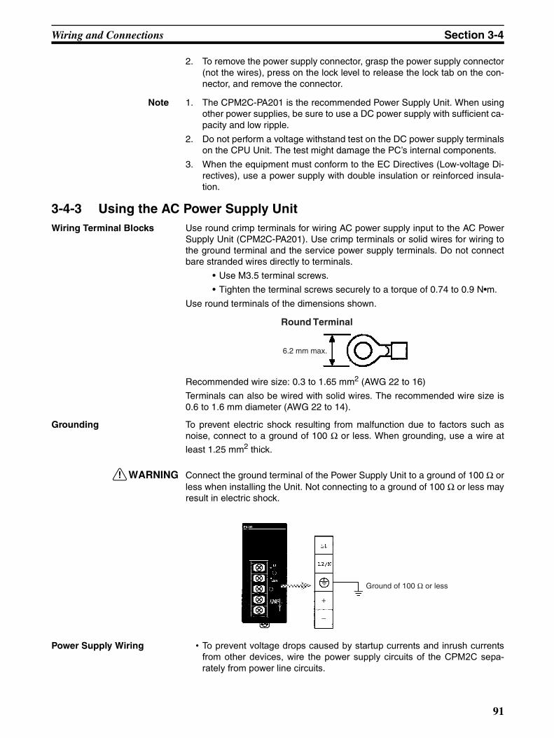
Wiring and Connections Section 3-4
2. To remove the power supply connector, grasp the power supply connector(not the wires), press on the lock level to release the lock tab on the con-nector, and remove the connector.
Note 1. The CPM2C-PA201 is the recommended Power Supply Unit. When usingother power supplies, be sure to use a DC power supply with sufficient ca-pacity and low ripple.
2. Do not perform a voltage withstand test on the DC power supply terminalson the CPU Unit. The test might damage the PC’s internal components.
3. When the equipment must conform to the EC Directives (Low-voltage Di-rectives), use a power supply with double insulation or reinforced insula-tion.
3-4-3 Using the AC Power Supply UnitWiring Terminal Blocks Use round crimp terminals for wiring AC power supply input to the AC Power
Supply Unit (CPM2C-PA201). Use crimp terminals or solid wires for wiring tothe ground terminal and the service power supply terminals. Do not connectbare stranded wires directly to terminals.
• Use M3.5 terminal screws.
• Tighten the terminal screws securely to a torque of 0.74 to 0.9 N•m.
Use round terminals of the dimensions shown.
Recommended wire size: 0.3 to 1.65 mm2 (AWG 22 to 16)
Terminals can also be wired with solid wires. The recommended wire size is0.6 to 1.6 mm diameter (AWG 22 to 14).
Grounding To prevent electric shock resulting from malfunction due to factors such asnoise, connect to a ground of 100 Ω or less. When grounding, use a wire at
least 1.25 mm2 thick.
!WARNING Connect the ground terminal of the Power Supply Unit to a ground of 100 Ω orless when installing the Unit. Not connecting to a ground of 100 Ω or less mayresult in electric shock.
Power Supply Wiring • To prevent voltage drops caused by startup currents and inrush currentsfrom other devices, wire the power supply circuits of the CPM2C sepa-rately from power line circuits.
Round Terminal
6.2 mm max.
Ground of 100 Ω or less
+
−
91

Wiring and Connections Section 3-4
• When using several CPM2C’s together, it is recommended that circuitsare wired separately in order to prevent circuit-breaker malfunctions andvoltage drops due to inrush current.
• Twist power supply lines to prevent noise from the power supply lines.Noise can further be prevented by wiring via a 1:1 isolation transformer.
• Use wires at least 1.25 mm2 thick in order to allow for voltage drops andto keep the current within the allowable level.
!WARNING Tighten the screws on the terminal block of the AC Power Supply Unit to atorque of 0.74 to 0.9 N•m. Loose screws may result in burning or malfunction.
The 24-VDC service power supply terminals on the terminal block can beused for input power supply.
Use the following to obtain the capacity of the service power supply that canbe used.
Example: CPU Unit + 5 Expansion I/O Units (1-W Power Consumption)
Power consumption = 4 (CPU Unit’s power consumption) + 1 (Expansion I/OUnit’s power consumption) × 5 (No. of Expansion I/O Units) = 9 (W)Service power supply current = (14.4 (CPM2C-PA201’s rated capacity) – 9(power consumption)) ÷ 24 (V) = 208 (mA)
!WARNING If the 24-VDC output (either the service power supply or the power supply tothe CPU Unit) is overloaded, or is short-circuited, the voltage will drop, andthe output will turn OFF. Take external countermeasures to ensure the safetyof the system in such an event. Failure to do so may result in a serious acci-dent.
!WARNING Do not connect a power supply to the service power supply terminals. If an ACpower supply is mistakenly connected to these terminals, the internal circuitrywill be damaged.
100 to 240 VAC
+
−
~
24 VDCCan be used for input power supply.
+
−
92
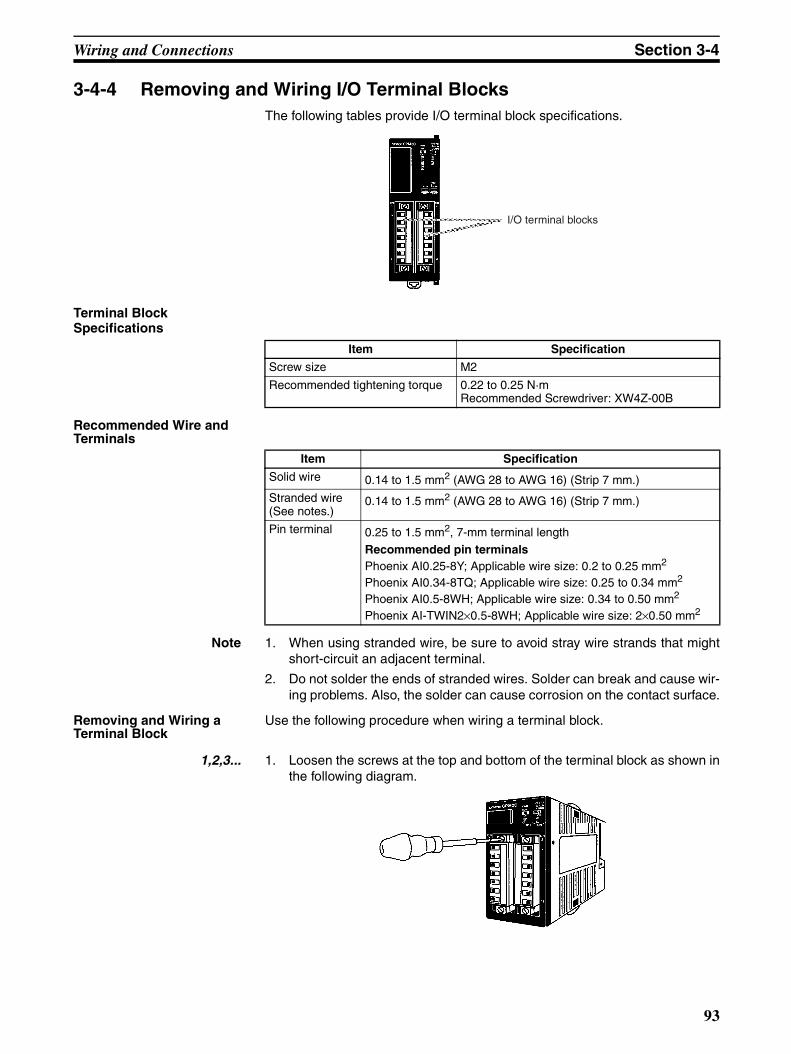
Wiring and Connections Section 3-4
3-4-4 Removing and Wiring I/O Terminal BlocksThe following tables provide I/O terminal block specifications.
Terminal Block Specifications
Recommended Wire and Terminals
Note 1. When using stranded wire, be sure to avoid stray wire strands that mightshort-circuit an adjacent terminal.
2. Do not solder the ends of stranded wires. Solder can break and cause wir-ing problems. Also, the solder can cause corrosion on the contact surface.
Removing and Wiring a Terminal Block
Use the following procedure when wiring a terminal block.
1,2,3... 1. Loosen the screws at the top and bottom of the terminal block as shown inthe following diagram.
I/O terminal blocks
Item Specification
Screw size M2
Recommended tightening torque 0.22 to 0.25 N·mRecommended Screwdriver: XW4Z-00B
Item Specification
Solid wire 0.14 to 1.5 mm2 (AWG 28 to AWG 16) (Strip 7 mm.)
Stranded wire (See notes.)
0.14 to 1.5 mm2 (AWG 28 to AWG 16) (Strip 7 mm.)
Pin terminal 0.25 to 1.5 mm2, 7-mm terminal lengthRecommended pin terminalsPhoenix AI0.25-8Y; Applicable wire size: 0.2 to 0.25 mm2
Phoenix AI0.34-8TQ; Applicable wire size: 0.25 to 0.34 mm2
Phoenix AI0.5-8WH; Applicable wire size: 0.34 to 0.50 mm2
Phoenix AI-TWIN2×0.5-8WH; Applicable wire size: 2×0.50 mm2
93
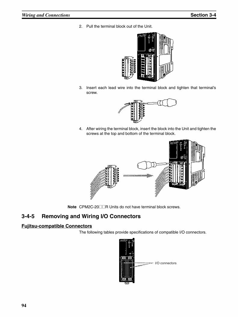
Wiring and Connections Section 3-4
2. Pull the terminal block out of the Unit.
3. Insert each lead wire into the terminal block and tighten that terminal’sscrew.
4. After wiring the terminal block, insert the block into the Unit and tighten thescrews at the top and bottom of the terminal block.
Note CPM2C-20@@R Units do not have terminal block screws.
3-4-5 Removing and Wiring I/O Connectors
Fujitsu-compatible ConnectorsThe following tables provide specifications of compatible I/O connectors.
I/O connectors
94

Wiring and Connections Section 3-4
Compatible Connector Specifications (OMRON)
Connector Specifications (Fujitsu)
Connecting I/O Connectors(Pressure Connectors)
Use the following procedure when connecting a pressure connector.
1,2,3... 1. Align the connector and insert it into the Unit.
Connector Specifications Model number
24-pin soldered con-nector and cover
Connector: Fujitsu FCN-361J024-AU equivalentCover: Fujitsu FCN-360C024-J2 equivalent
C500-CE241
24-pin crimp connec-tor and cover
Housing: Fujitsu FCN-363J024 equivalentContacts: Fujitsu FCN-363J-AU equivalentCover: Fujitsu FCN-360C024-J2 equivalent
C500-CE242
24-pin pressure con-nector
Connector: Fujitsu FCN-367J024-AU/F equivalent C500-CE243
Item Specifications Model number
Soldered jack 24-pin gold-plated terminals FCN-361J024-AU
Crimp con-nector
Crimp jack housing 24-pin FCN-363J024
Crimp contacts For wire gauges 24 AWG to 28 AWG FCN-363J-AU
Hand crimp tool --- FCN-363T-T005/H
Contact removal tool --- FCN-360T-T001/H
Pressure connector
Pressure jack with closed end cover
24-pin gold-plated terminals FCN-367J024-AU/F
24-pin silver-plated terminals FCN-367J024-AG/F
Pressure jack with open end cover
24-pin gold-plated terminals FCN-367J024-AU/H
24-pin silver-plated terminals FCN-367J024-AG/H
Pressing tools
Hand press General purpose FCN-707T-T101/H
Cable cutter General purpose FCN-707T-T001/H
Locator plate For the 360-series connectors FCN-367T-T012/H
Connector cover(Not compatible with the closed-end cover pressure jack.)
Thin slanted cover for 24-pin connector FCN-360C024-J2
With slotted screws for 24-pin connector(Can be turned by hand.)
FCN-360C024E
With Phillips-head screws for 24-pin connector FCN-360C024B
With intermediate Phillips-head screws for 24-pin connector
FCN-360C024C
95

Wiring and Connections Section 3-4
2. Use a flat-blade screwdriver to tighten the connector’s fastening screws.
Connecting I/O Connectors(Soldered Connectors)
Use the following procedure when connecting a soldered connector.
1,2,3... 1. Align the connector and insert it into the Unit.
2. Use a Phillips screwdriver to tighten the connector’s fastening screws.
Assembling Soldered Connectors
Use the following procedure when wiring and assembling a soldered connec-tor (OMRON C500-CE241).
1,2,3... 1. Slide heat-shrink tubing over the power supply wires and solder the wiresto the appropriate pins on the socket.
Flat-blade screwdriver
Phillips screwdriver
Heat-shrink tubingPower supply wires
Connector
96

Wiring and Connections Section 3-4
2. After soldering all of the pins, slide the heat-shrink tubing over the solderedpower supply pins and shrink the tubing by heating it with a heat gun.
3. Assemble the socket and connector as shown in the following diagram.
MIL ConnectorsThe following tables provide specifications of compatible I/O connectors.
Compatible MIL Connector Specifications (OMRON)
MIL Flat Cable Connectors
Note The rated current for the flat cable is 1 A max. Do not allow the common termi-nal current to exceed 1 A.
Heat-shrink tubing
Connector cover
Socket
Nuts (3)
Nuts (2)
Connector screws
Small screws (2)Cable clamp
Small screws (3)
I/O connectors
Polarity slots (notches)
Name Model
Socket XG4M-2030
Strain Relief XG4T-2004
Set model number XG4M-2030-T
Recommended Flat Cable XY3A-200@
Strain Relief
Socket
Set
97

Wiring and Connections Section 3-4
Crimp Tools (OMRON)
MIL Loose-wire, Pressure-fitted Connectors
Pressure Fitting Tools (OMRON)
Connecting and Disconnecting MIL I/O Connectors
Use the following procedure to connect and disconnect MIL I/O connectors.
1,2,3... 1. Open the lock levers on both sides of the connector before connecting thecable.
2. Insert the cable into the connector and press in firmly until the lock leverslock into place.
Crimp Tool XY2B-0002
Attachment XY2B-1007
Name Model
Socket AWG24 XG5M-2032-N
AWG26 to AWG28 XG5M-2035-N
Hood Cover XG5S-2012
Semi-cover(Two required for each Socket.)
XG5S-1001
Pressure Fitting Tool Set (Handiplex) XY2B-2104
Simple Pressure Fitting Tool XY2B-7006
Hood Cover
Semi-cover
Sockets
98

Wiring and Connections Section 3-4
3. To remove the cable, pull the lock lever out to the sides to release the lockmechanism and pull out the connector.
Note Be sure to make connections to terminal blocks and connectors with the cor-rect direction and polarity. Output transistor fuses may burn out if power issupplied to I/O circuits with the I/O connector connected in reverse.
99

Wiring and Connections Section 3-4
3-4-6 Using I/O Terminals and Relay TerminalsWe recommend using the following I/O Terminals and Relay Terminals to wiredevices to the CPM2C’s I/O connector.
Cables (See note.)Fujitsu-compatible connectors: XW2Z-@@@A, G79-@@@CMIL connectors: G79-O@@C
Terminal BlocksXW2B-20G4 (M3 screws)XW2B-20G5 (M3.5 screws)XW2D-20G6
Cables (See note.)Fujitsu-compatible connectors: XW2Z-@@@AMIL connectors: G79-O@@C
Relay TerminalsG7TC-ID16G7TC-IA16
Cables (See note.)Fujitsu-compatible connectors: XW2Z-@@@A G79-@@@CMIL connectors: G79-O@@C
Terminal BlocksXW2B-20G4 (M3 screws)XW2B-20G5 (M3.5 screws)XW2D-20G6
CablesFujitsu-compatible connectors: G79-@@@CMIL connectors: G79-O@@C
Relay TerminalsG7OD-OC16G7OD-OC16-1G7OD-SOC16G7OD-SOC16-1G7OD-FOM16G7OD-FOM16-1
CablesFujitsu-compatible connectors:
G79-@@@CMIL connectors:
G79-O@@C
Relay TerminalsG7TC-OC08G7TC-OC16G7TC-OC16-1
Relay Terminals
Note The allowable current for the XW2Z-@@@A is 1 A. Do not allow the current on the common terminal to exceed 1 A.
CablesFujitsu-compatible connectors: G79-@@@CMIL connectors: G79-O@@C
Terminal BlocksXW2C-20G5-IN16 (M3.5 screws)XW2E-20G5-IN16
Outputs
Inputs
G70A-ZOC16-4 G79-I@@C (G70A-ZOC16-9)(G70A-ZOC16-5)
(G70A-ZOC16-3)
G70A-ZOC16-3
100

Wiring and Connections Section 3-4
3-4-7 Connecting Input DevicesWire inputs to the CPM2C’s CPU Unit and Expansion I/O Units as shown inthe following diagrams.
Note 1. Be sure to make connections to terminal blocks and connectors with thecorrect direction and polarity. Output transistor fuses may burn out if poweris supplied to I/O circuits with the I/O connector connected in reverse.
2. When equipment must conform to the EC Directives (Low-voltage Direc-tives), use a power supply with double insulation or reinforced insulation.
Units with Relay Outputs via Terminal Block
The following diagrams show the input configurations.
CPU Units with 10 I/O Points: CPM2C-10C@DR-D
CPU Units with 20 I/O Points: CPM2C-20C@DR-D
Input devices
24 VDC
Inputs: IR 000
7
6
5
4
3
2
1
COM
00005
00004
00003
00002
00001
00000
Input devices
24 VDC
Inputs: IR 000
13
12
11
10
9
8
7
6
5
4
3
2
1
COM
00011
00010
00009
00008
00007
00006
00005
00004
00003
00002
00001
00000
101

Wiring and Connections Section 3-4
Expansion I/O Unit with 10 I/O Points: CPM2C-10EDR
Expansion I/O Unit with 20 I/O Points: CPM2C-20EDR
Units with Transistor Outputs via Fujitsu-compatible Connector
CPU Units with 10 I/O Points: CPM2C-10C@DT@C-D
Input devices
24 VDC Inputs: IR word m
COM
0005
0004
0003
0002
0001
0000
7
6
5
4
3
2
1
Input devices
24 VDC Inputs: IR word m
COM
0005
0004
0003
0002
0001
0000
0011
0010
0009
0008
0007
0006
13
12
11
10
9
8
7
6
5
4
3
2
1
Input devices
24 VDC
Inputs: IR 000
102

Wiring and Connections Section 3-4
CPU Units with 20 I/O Points: CPM2C-20C@DT@C-D
Note COM terminals (A9 and B9) are connected internally.
CPU Units with 32 I/O Points: CPM2C-32CDT@C-D
Note COM terminals (A9 and B9) are connected internally.
Input devices Input devices
24 VDC
COM COM
00011
00010
00009
00008
00007
00006
00005
00004
00003
00002
00001
00000
B A
12
11
10
9
8
7
6
5
4
3
2
1
12
11
10
9
8
7
6
5
4
3
2
1
Inputs: IR 000
Input devices Input devices
24 VDC
Inputs: IR 000/IR001
B A
12
11
10
9
8
7
6
5
4
3
2
1
12
11
10
9
8
7
6
5
4
3
2
1
COM
00007
00006
00005
00004
00003
00002
00001
00000
COM
00107
00106
00105
00104
00103
00102
00101
00100
103

Wiring and Connections Section 3-4
Expansion I/O Units with 24 I/O Points: CPM2C-24EDT@C
Note COM terminals (A9 and B9) are connected internally.
Expansion I/O Units with 32 I/O Points: CPM2C-32EDT@C
Note COM terminals (A9 and B9) are connected internally.
Inputs: IR word m
Input devices Input devices
24 VDC
COM COM
0011
0010
0009
0008
0007
0006
0005
0004
0003
0002
0001
0000
0012
0013
0014
0015
B A12
11
10
9
8
7
6
5
4
3
2
1
12
11
10
9
8
7
6
5
4
3
2
1
Inputs: IR word m
Input devices Input devices
24 VDC
B A
12
11
10
9
8
7
6
5
4
3
2
1
12
11
10
9
8
7
6
5
4
3
2
1
COM
0005
0004
0003
0002
0001
0000
0011
0010
0009
0008
0007
0006
COM
0015
0014
0003
0001
104

Wiring and Connections Section 3-4
Expansion I/O Unit with 8 Input Points: CPM2C-8EDC
Expansion I/O Unit with 16 Input Points: CPM2C-16EDC
Note COM terminals (A9 and B9) are connected internally.
Input devices
24 VDC
COM
0007
0006
0005
0004
0003
0002
0001
0000
B A
12
11
10
9
8
7
6
5
4
3
2
1
12
11
10
9
8
7
6
5
4
3
2
1
Inputs: IR word m
Input devices Input devices
24 VDC
COM
00 15
00 14
00 13
00 12
00 11
00 10
00 09
00 08
COM
00 07
00 06
00 05
00 04
00 03
00 02
00 01
00 00
B A
12
11
10
9
8
7
6
5
4
3
2
1
12
11
10
9
8
7
6
5
4
3
2
1
Inputs: IR word m
105

Wiring and Connections Section 3-4
Units with Transistor Outputs via MIL Connector
CPU Units with 10 I/O Points: CPM2C-10C@DT@M-D
CPU Units with 20 I/O Points: CPM2C-20C@DT@M-D
Note COM terminals (3 and 4) are connected internally.
Input devices
24 VDC
Inputs: IR 000
COM
00005
00004
00003
00002
00001
00000
12 11
10 9
8 7
6 5
4 3
2 1
16 15
14 13
20 19
18 17
Input devices
24 VDC
Inputs: IR 000
Input devices
12 11
10 9
8 7
6 5
4 3
2 1
16 15
14 13
20 19
18 17
COM
00005
00004
00003
00002
00001
00000
00007
00006
00009
00008
00011
00010
COM
106
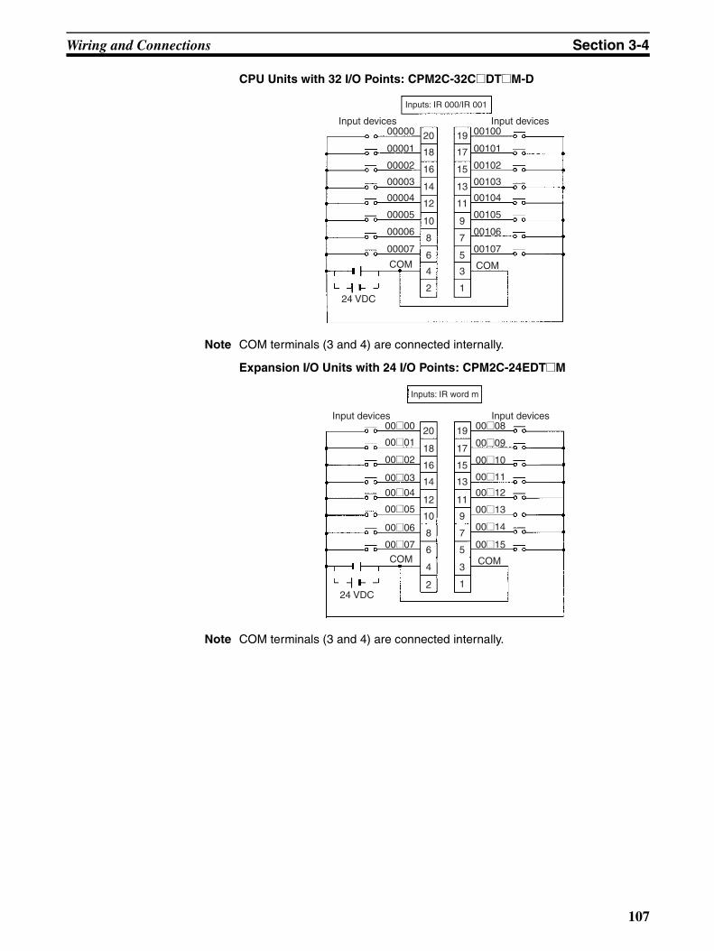
Wiring and Connections Section 3-4
CPU Units with 32 I/O Points: CPM2C-32C@DT@M-D
Note COM terminals (3 and 4) are connected internally.
Expansion I/O Units with 24 I/O Points: CPM2C-24EDT@M
Note COM terminals (3 and 4) are connected internally.
Input devices
24 VDC
Inputs: IR 000/IR 001
Input devices
12 11
10 9
8 7
6 5
4 3
2 1
16 15
14 13
20 19
18 17
COM
00005
00004
00003
00002
00001
00000
00007
00006
COM
00105
00104
00103
00102
00101
00100
00107
00106
Input devices
24 VDC
Inputs: IR word m
Input devices
0015
0014
0013
0012
0011
0010
0009
0008
0007
0006
0005
0004
0003
0002
0001
0000
12 11
10 9
8 7
6 5
4 3
2 1
16 15
14 13
20 19
18 17
COM COM
107

Wiring and Connections Section 3-4
Expansion I/O Units with 32 I/O Points: CPM2C-32EDT@M
Note COM terminals (3 and 4) are connected internally.
Expansion I/O Units with 8 Input Points: CPM2C-8EDM
Expansion I/O Units with 16 Input Points: CPM2C-16EDM
Input devices
24 VDC
Inputs: IR word m
Input devices
0015
0014
0013
0012
0011
0010
0009
0008
0007
0006
0005
0004
0003
0002
0001
0000
12 11
10 9
8 7
6 5
4 3
2 1
16 15
14 13
20 19
18 17
COM COM
Input devices
24 VDC
Inputs: IR word m
0007
0006
0005
0004
0003
0002
0001
0000
12 11
10 9
8 7
6 5
4 3
2 1
16 15
14 13
20 19
18 17
COM
Input devices
24 VDC
Inputs: IR word m
Input devices
0015
0014
0013
0012
0011
0010
0009
0008
0007
0006
0005
0004
0003
0002
0001
0000
12 11
10 9
8 7
6 5
4 3
2 1
16 15
14 13
20 19
18 17
COM COM
108

Wiring and Connections Section 3-4
Note COM terminals (3 and 4) are connected internally.
Wiring Input Terminals The wiring for input terminals is as shown below.
Note For CPU Units with 32 I/O Points, relay numbers 00@00 to 00@07 correspondto 00000 to 00007, relay numbers 00@08 to 00@15 correspond to 00100 to00107, and relay numbers 01@00 to 01@07 correspond to 01000 to 01007,and relay numbers 01@08 to 01@15 correspond to 01100 to 01107.
Terminal Blocks: XW2B-20G4, XW2B-20G5
Cable: XW2Z-@@@A (Fujitsu-compatible connector) Cable: G79-@C (Fujitsu-compatible connector), G79-O@@C (MIL connector)
COM
00 07
00 06
00 05
00 04
00 03
00 02
00 01
00 00
COM
00 15
00 14
00 13
00 12
00 11
00 10
00 09
00 08
NCNC 19
17
15
13
11
9
75
3
1
20
18
16
14
12
10
8
6
4
2
COM
00 07
00 06
00 05
00 04
00 03
00 02
00 01
00 00
COM
00 15
00 14
00 13
00 12
00 11
00 10
00 09
00 08
NCNC
19
17
15
13
11
9
7
53
1
20
18
16
14
12
10
8
6
42
Terminal Blocks: XW2D-20G6
Cable: XW2Z-@@@A (Fujitsu-compatible connector) Cable: G79-@C (Fujitsu-compatible connector), G79-O@@C (MIL connector)
COM
00 07
00 06
00 05
00 04
00 03
00 02
00 01
00 00
COM
00 15
00 14
00 13
00 12
00 11
00 10
00 09
00 08
NCNC A10
A9
A8
A7
A6
A5
A4
A3
A2
A1
B10
B9
B8
B7
B6
B5
B4
B3
B2
B1
COM
00 07
00 06
00 05
00 04
00 03
00 02
00 01
00 00
COM
00 15
00 14
00 13
00 12
00 11
00 10
00 09
00 08
NCNC
A10
A9
A8
A7
A6
A5
A4
A3
A2
A1
B10
B9
B8
B7
B6
B5
B4
B3
B2
B1
109

Wiring and Connections Section 3-4
Terminal Block: XW2C-20G5-IN16 Relay Terminals: XW2E-20G5-IN16
Cable: XW2Z-@@@A (Fujitsu-compatible connector) Cable: XW2Z-@@@A (Fujitsu-compatible connector)
00 15
00 14
00 13
00 12
00 11
00 10
00 09
00 08
00 07
00 06
00 05
00 04
00 03
00 02
00 01
00 00
33
31
29
27
25
23
2119
17
15
13
11
9
7
5
3
1
34
32
30
28
26
24
22
20
18
16
14
1210
8
6
4
2
00 15
00 14
00 13
00 12
00 11
00 10
00 09
00 08
00 07
00 06
00 05
00 04
00 03
00 02
00 01
00 00
15
14
13
12
11
10
9
8
7
6
5
4
3
2
1
0
+
+
+
+
+
+
+
+
+
+
+
+
+
+
+
++
−−−−−−−−−−−−−−−−−
110

Wiring and Connections Section 3-4
Terminal Blocks: XW2C-20G6-IO16
Cable: XW2Z-@@@A (Fujitsu-compatible connector)
Connecting COM to – Terminal Connecting COM to + Terminal
15
14
13
12
11
10
9
8
7
6
5
4
3
2
1
0
00 15
00 14
00 13
00 12
00 11
00 10
00 09
00 08
00 07
00 06
00 05
00 04
00 03
00 02
00 01
00 00
COM
A9B9
+
+
+
+
+
+
+
+
+
+
+
A10B10
−−
−−−
−−
−−−
−
−
−
−
15
1413
12
11
10
9
8
7
6
5
4
3
2
10
00 15
00 14
00 13
00 12
00 11
00 10
00 09
00 08
00 07
00 06
00 05
00 04
00 03
00 02
00 01
00 00
COM
A9B9
+
+
A10B10
+
+
+
+
+
+
+
+
+
−−
−
−
−
−
−
−
−
−
−
111

Wiring and Connections Section 3-4
Relay Terminals: G7TC-ID16, G7TC-IA16
Cable: G79-@C (Fujitsu-compatible connector), G79-O@@C (MIL connector)
00 15
00 14
00 13
00 12
00 11
00 10
00 09
00 08
00 07
00 06
00 05
00 04
00 03
00 02
00 01
00 00
C15
C14
C13
C12
C11
C10
C9
C8
C7
C6
C5
C4
C2
C1
C0
C3
15
14
13
12
11
10
9
8
7
6
5
4
32
1
0
+−
112

Wiring and Connections Section 3-4
Input Devices The following table shows how to connect various input devices.
Note Do not use the following wiring with voltage-output devices:
Device Circuit diagram
Relay output
NPN open collector
NPN current output
PNP current output
Voltage output
IN
COM (+)
5 mA/6 mA/8 mACPM2C
IN
COM (+)
Sensor power supply
Output
5 mA/6 mA/8 mACPM2C
0 V
Use the same power supply forthe input and sensor.
CPM2CIN
COM (+)
Output
5 mA/6 mA/8 mA
0 V
Constant current circuit
+
Sensor power supply
COM (+)0 V
INOutput
5 mA/6 mA/8 mACPM2C
Sensor power supply
IN
COM (+)
0 V
OutputCPM2C
COM(+)
IN
0 V
OutputCPM2C
Sensor power supply
Incorrect Wiring
113

Wiring and Connections Section 3-4
High-speed Counter InputsUsing IR 00000 to IR 00002 as High-speed Counter InputsIn these examples, Encoders with an external 24-VDC open-collector outputare connected.
Note *CW is clockwise and CCW is counter-clockwise.Using IR 00003 to IR 00006 as Interrupt Inputs (Counter Mode)In these examples, an Encoder with an external 24-VDC open-collector outputis connected.
PC Setup Settings The input bits shown in the following tables can operate as normal inputs orthey can be assigned special functions in the PC Setup.Special functions for input bits IR 00000 through IR 00002 are set inDM 6642:
Differential Phase Mode (Count frequency: 5 kHz)
Encoder
24 VDC
00000 A-phase input
00001 B-phase input
COM
00002 Z-phase input
Pulse Plus Direction Input Mode (Count frequency: 20 kHz)
Encoder
24 VDC
00000 Pulse input
00001 Direction input
COM
00002 Reset input
Sensor or switch
CPM2C CPM2C
Up/Down Mode(Count frequency: 20 kHz)
24 VDC
00000 CW input*
00001 CCW input*
COM
00002 Reset input
Increment Mode(Count frequency: 20 kHz)
Encoder
24 VDC
00000 Pulse input
00001 Normal input
COM
00002 Normal input
CPM2C CPM2C
Sensor
Sensor
Sensor or switch
Sensor or switch
Increment or decrement(Count frequency: 2 kHz)
Encoder
24 VDC
Input (00003 to 00006)
COM
CPM2C
Bit address
PC Setup setting (DM 6642 bits 08 to15)
00 01 02, 03, or 04
IR 00000 Used as normal inputs.
Used as high-speed counter inputs.
Used as inputs for syn-chronized pulse control.IR 00001
IR 00002 Used as a normal input.
114
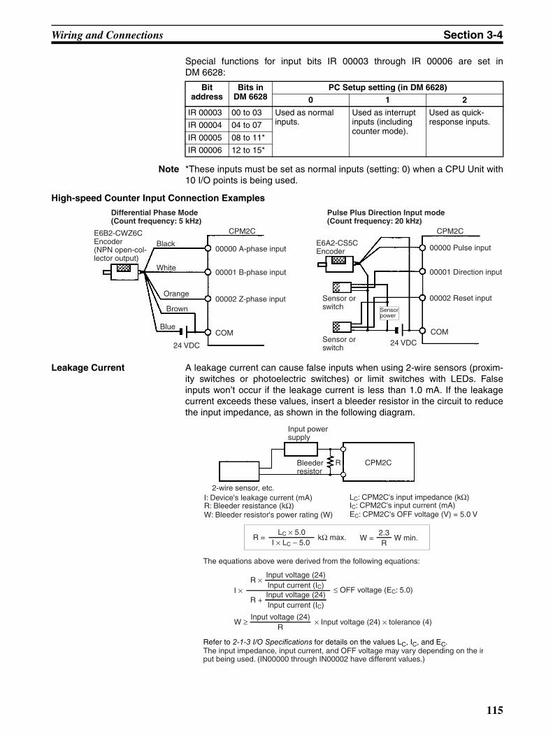
Wiring and Connections Section 3-4
Special functions for input bits IR 00003 through IR 00006 are set inDM 6628:
Note *These inputs must be set as normal inputs (setting: 0) when a CPU Unit with10 I/O points is being used.
High-speed Counter Input Connection Examples
Leakage Current A leakage current can cause false inputs when using 2-wire sensors (proxim-ity switches or photoelectric switches) or limit switches with LEDs. Falseinputs won’t occur if the leakage current is less than 1.0 mA. If the leakagecurrent exceeds these values, insert a bleeder resistor in the circuit to reducethe input impedance, as shown in the following diagram.
Bit address
Bits in DM 6628
PC Setup setting (in DM 6628)
0 1 2
IR 00003 00 to 03 Used as normal inputs.
Used as interrupt inputs (including counter mode).
Used as quick-response inputs.IR 00004 04 to 07
IR 00005 08 to 11*
IR 00006 12 to 15*
Differential Phase Mode (Count frequency: 5 kHz)
E6B2-CWZ6C Encoder(NPN open-col-lector output)
24 VDC
00000 A-phase input
00001 B-phase input
COM
00002 Z-phase input
Pulse Plus Direction Input mode (Count frequency: 20 kHz)
E6A2-CS5C Encoder
24 VDC
00000 Pulse input
00001 Direction input
COM
00002 Reset inputSensor or switch
CPM2C CPM2C
Sensor or switch
Sensor power
Black
White
Orange
Brown
Blue
R CPM2C
Input power supply
Bleeder resistor
2-wire sensor, etc.I: Device's leakage current (mA)R: Bleeder resistance (kΩ)W: Bleeder resistor's power rating (W)
The equations above were derived from the following equations:
LC: CPM2C's input impedance (kΩ)IC: CPM2C's input current (mA)EC: CPM2C's OFF voltage (V) = 5.0 V
The input impedance, input current, and OFF voltage may vary depending on the input being used. (IN00000 through IN00002 have different values.)
W = R = W min. kΩ max. LC × 5.0
I × LC − 5.0
× Input voltage (24) × tolerance (4)W ≥ Input voltage (24)
R
I × ≤ OFF voltage (EC: 5.0)R ×
Input voltage (24)Input current (IC)
R + Input voltage (24)Input current (IC)
2.3R
Refer to 2-1-3 I/O Specifications for details on the values LC, IC, and EC.
115

Wiring and Connections Section 3-4
Inductive Loads When connecting an inductive load to an input, connect a diode in parallelwith the load. The diode should satisfy the following requirements:
1,2,3... 1. Peak reverse-breakdown voltage must be at least 3 times the load voltage.
2. Average rectified current must be 1 A.
3-4-8 Connecting Output DevicesWire the outputs to the CPM2C’s CPU Unit and Expansion I/O Unit as shownin the following diagrams.
Don’t exceed the output capacity or the maximum common current shown inthe following table.
!WARNING The PC outputs may remain ON or OFF due to deposits on or burning of theoutput relays or destruction of the output transistors. External safety mea-sures must be provided to ensure safety in the system. Not providing propersafety measures may result in serious accidents.
Units with Relay Outputs via Terminal Block
Note 1. Be sure to make connections to terminal blocks and connectors with thecorrect direction and polarity. Output transistor fuses may burn out if poweris supplied to I/O circuits with the I/O connector connected in reverse.
2. Basic insulation is provided between the commons of different polarities ofthe output relay for the CPM2C-20@@R (model with 20 relay outputpoints).Therefore, to conform to EC Directives (Low Voltage Directive), when con-necting devices that operate at voltages higher than 50 VAC and those thatoperate on DC power supplies to adjoining relay output terminals, use dif-ferent DC power supplies for output devices from those for input devicesand the CPM2C power supply.
3. If input status is being held in HR area bits or counter values are being heldwhen the power supply turns OFF, configure the system so that the I/Opower supply turns OFF after the power supply to the CPM2C or delayreading the status of inputs.
IN
COM
CPM2CDiode
116

Wiring and Connections Section 3-4
CPU Units with 10 I/O Points: CPM2C-10C@DR-D
Output capacity Max. common capacity
2 A (250 VAC or 24 VDC) 4 A/common
CPM2 operation
Stopped
24 V
0 V
Power interrupted
Operation continues for 2 ms or longer.
CPM2C operating
Input power supply
Power interruption detected
This time lag causes detection of an OFF status for inputs.
Outputs: IR 010
Load
Load
Load
Load
117

Wiring and Connections Section 3-4
CPU Units with 20 I/O Points: CPM2C-20C@DR-D
Note Terminals 12 and 13 are internally connected. The maximum common capac-ity is the same as for other common circuits.
Expansion I/O Unit with 10 I/O Points: CPM2C-10EDR
Output capacity Max. common capacity
2 A (250 VAC or 24 VDC) 4 A/common
Outputs: IR 010
Load
Load
Load
Load
Load
Load
Load
Load
Output capacity Max. common capacity
2 A (250 VAC or 24 VDC) 4 A/common
Outputs: IR word n
Load
Load
Load
Load
118

Wiring and Connections Section 3-4
Expansion I/O Unit with 20 I/O Points: CPM2C-20EDR
Note Terminals 12 and 13 are internally connected. The maximum common capac-ity is the same as for other common circuits.
Expansion I/O Unit with 8 Output Points: CPM2C-8ER
Output capacity Max. common capacity
2 A (250 VAC or 24 VDC) 4 A/common
Outputs: IR word n
Load
Load
Load
Load
Load
Load
Load
Load
Output capacity Max. common capacity
2 A (250 VAC/24 VDC) 4 A/common
COM
01@02
01@01
COM
01@03
COM
01@00
01@04
01@05
01@06
01@07
COM
COM
COM
7
6
5
4
3
2
1
1
2
3
4
5
6
7
Outputs: IR word n
Load
Load
Load
Load
Load
Load
Load
Load
119

Wiring and Connections Section 3-4
Units with Transistor Outputs via Fujitsu-compatible ConnectorCPU Units with 10 I/O Points, Sinking Outputs: CPM2C-10C@DTC-D
CPU Units with 10 I/O Points, Sourcing Outputs: CPM2C-10C@DT1C-D
Output capacity Max. common capacity
300 mA (24 VDC) 1.2 A/common
Output capacity Max. common capacity
300 mA (24 VDC) 1.2 A/common
Outputs: IR 010
Load
Load
Load
Load
24 VDC
A B
COM
24V
Outputs: IR 010
Load
Load
Load
Load
24 VDC
COM
0V
A B
120

Wiring and Connections Section 3-4
CPU Units with 20 I/O Points, Sinking Outputs: CPM2C-20C@DTC-D
CPU Units with 20 I/O Points, Sourcing Outputs: CPM2C-20C@DT1C-D
Output capacity Max. common capacity
300 mA (24 VDC) 2.4 A/common
Output capacity Max. common capacity
300 mA (24 VDC) 2.4 A/common
Outputs: IR 010
Load
Load
Load
Load
24 VDC
Load
Load
Load
Load
A B
COM
24V
Outputs: IR 010
Load
Load
Load
Load
24 VDC
Load
Load
Load
LoadCOM
0V
A B
121

Wiring and Connections Section 3-4
CPU Units with 32 I/O Points, Sinking Outputs: CPM2C-32CDTC-D
Note Wire COM terminals (A9 and B9) and 24-V terminals (A10 and B10) eventhough they are connected internally.
CPU Units with 32 I/O Points, Sourcing Outputs: CPM2C-32CDT1C-D
Note Wire COM terminals (A9 and B9) and 0-V terminals (A10 and B10) eventhough they are connected internally.
Output capacity Max. common capacity
OUT01000 to OUT01007:300 mA (24 VDC)OUT01100 to OUT01107:100 mA (24 VDC)
3.2 A/common
Outputs: IR 010/IR011
Load
Load
Load
Load
Load
Load
Load
Load
24 VDC
Load
Load
Load
Load
Load
Load
Load
Load
Output capacity Max. common capacity
OUT01000 to OUT01007:300 mA (24 VDC)OUT01100 to OUT01107:100 mA (24 VDC)
3.2 A/common
Outputs: IR 010/IR011
Load
Load
Load
Load
Load
Load
Load
Load
24 VDC
Load
Load
Load
Load
Load
Load
Load
Load
122

Wiring and Connections Section 3-4
Expansion I/O Unit with 24 I/O Points, Sinking Outputs: CPM2C-24EDTC
Expansion I/O Unit with 24 I/O Points, Sourcing Outputs: CPM2C-24EDT1C
Output capacity Max. common capacity
300 mA (24 VDC) 2.4 A/common
Output capacity Max. common capacity
300 mA (24 VDC) 2.4 A/common
Outputs: IR word n
Load
Load
Load
Load
24 VDC
Load
Load
Load
Load
0100
COM
0101
0102
0103
0104
0105
0106
0107
24 V
Outputs: IR word n
Load
Load
Load
Load
24 VDC
Load
Load
Load
Load
01@00
COM
01@01
01@02
01@03
01@04
01@05
01@06
01@07
0 V
123

Wiring and Connections Section 3-4
Expansion I/O Unit with 32 I/O Points, Sinking Outputs: CPM2C-32EDTC
Note Wire COM terminals (A9 and B9) and 24-V terminals (A10 and B10) eventhough they are connected internally.
Expansion I/O Unit with 32 I/O Points, Sourcing Outputs:CPM2C-32EDT1C
Note Wire COM terminals (A9 and B9) and 0-V terminals (A10 and B10) eventhough they are connected internally.
Output capacity Max. common capacity
00 to 07: 300 mA (24 VDC)08 to 15: 100 mA (24 VDC)
3.2 A/common
Outputs: IR word n
Load
Load
Load
Load
Load
Load
Load
Load
Load
Load
Load
Load
24 VDC
Load
Load
Load
Load
Output capacity Max. common capacity
00 to 07: 300 mA (24 VDC)08 to 15: 100 mA (24 VDC)
3.2 A/common
Outputs: IR word n
Load
Load
Load
Load
Load
Load
Load
Load
Load
Load
Load
Load
24 VDC
Load
Load
Load
Load
01
01
01
01
01
01
01
01
124

Wiring and Connections Section 3-4
Expansion I/O Unit with 8 Sinking Output Points: CPM2C-8ETC
Expansion I/O Unit with 8 Sourcing Output Points: CPM2C-8ET1C
Output capacity Max. common capacity
300 mA (24 VDC) 2.4 A/common
Output capacity Max. common capacity
300 mA (24 VDC) 2.4 A/common
Outputs: IR word n
0103
0102
0101
0100
COM
0106
0107
0104
0105
Load
24 VDC 24V
Load
Load
Load
Load
Load
Load
Load
1
2
3
4
5
6
7
B
8
9
10
11
12
1
2
3
4
5
6
7
A
8
9
10
11
12
0103
0102
0101
0100
COM
0106
0107
0104
0105
Load
24 VDC 0V
Load
Load
Load
Load
Load
Load
Load
Outputs: IR word n
1
2
3
4
5
6
7
B
8
9
10
11
12
1
2
3
4
5
6
7
A
8
9
10
11
12
125

Wiring and Connections Section 3-4
Expansion I/O Unit with 16 Sinking Output Points: CPM2C-16ETC
Note Wire COM terminals (A9 and B9) and 24-V terminals (A10 and B10) eventhough they are connected internally.
Expansion I/O Unit with 16 Sourcing Output Points: CPM2C-16ET1C
Note Wire COM terminals (A9 and B9) and 0-V terminals (A10 and B10) eventhough they are connected internally.
Output capacity Max. common capacity
00 to 07: 300 mA (24 VDC)08 to 15: 100 mA (24 VDC)
3.2 A/common
0103
0102
0101
0100
COM
0106
0107
0104
0105
Load
24 VDC24V
Load
Load
Load
Load
Load
Load
Load
Outputs: IR word n
0111
0110
0109
0108
COM
0114
0115
0112
0113
24V
Load
Load
Load
Load
Load
Load
Load
Load
1
2
3
4
5
6
7
B
8
9
10
11
12
1
2
3
4
5
6
7
A
8
9
10
11
12
Output capacity Max. common capacity
00 to 07: 300 mA (24 VDC)08 to 15: 100 mA (24 VDC)
3.2 A/common
0103
0102
0101
0100
COM
0106
0107
0104
0105
Load
24 VDC0V
Load
Load
Load
Load
Load
Load
Load
Outputs: IR word n
0111
0110
0109
0108
COM
0114
0115
0112
0113
0V
Load
Load
Load
Load
Load
Load
Load
Load
1
2
3
4
5
6
7
B
8
9
10
11
12
1
2
3
4
5
6
7
A
8
9
10
11
12
126
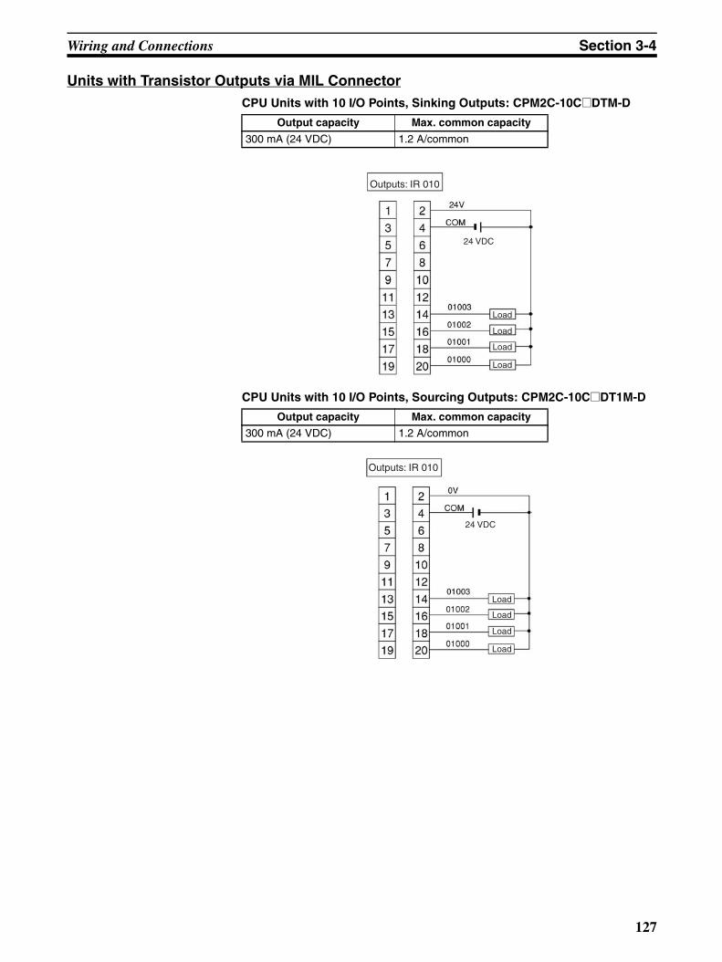
Wiring and Connections Section 3-4
Units with Transistor Outputs via MIL ConnectorCPU Units with 10 I/O Points, Sinking Outputs: CPM2C-10C@DTM-D
CPU Units with 10 I/O Points, Sourcing Outputs: CPM2C-10C@DT1M-D
Output capacity Max. common capacity
300 mA (24 VDC) 1.2 A/common
Output capacity Max. common capacity
300 mA (24 VDC) 1.2 A/common
24 VDC
Outputs: IR 010
Load
Load
Load
Load
24 VDC
Outputs: IR 010
Load
Load
Load
Load
127

Wiring and Connections Section 3-4
CPU Units with 20 I/O Points, Sinking Outputs: CPM2C-20C@DTM-D
CPU Units with 20 I/O Points, Sourcing Outputs: CPM2C-20C@DT1M-D
Output capacity Max. common capacity
300 mA (24 VDC) 2.4 A/common
Output capacity Max. common capacity
300 mA (24 VDC) 2.4 A/common
24 VDC
Outputs: IR 010
Load
Load
Load
Load
Load
Load
Load
Load
24 VDC
Outputs: IR 010
Load
Load
Load
Load
Load
Load
Load
Load
128

Wiring and Connections Section 3-4
CPU Units with 32 I/O Points, Sinking Outputs: CPM2C-32CDTM-D
Note Wire COM terminals (3 and 4) and 24-V terminals (1 and 2) even though theyare connected internally.
CPU Units with 32 I/O Points, Sourcing Outputs: CPM2C-32CDT1M-D
Note Wire COM terminals (3 and 4) and 0-V terminals (1 and 2) even though theyare connected internally.
Output capacity Max. common capacity
OUT01000 to OUT01007:300 mA (24 VDC)OUT01100 to OUT01107:100 mA (24 VDC)
3.2 A/common
24 VDC
Outputs: IR 010/IR 011
Load
Load
Load
Load
Load
Load
Load
Load
Load
Load
Load
Load
Load
Load
Load
Load
Output capacity Max. common capacity
OUT01000 to OUT01007:300 mA (24 VDC)OUT01100 to OUT01107:100 mA (24 VDC)
3.2 A/common
24 VDC
Outputs: IR 010/IR 011
Load
Load
Load
Load
Load
Load
Load
Load
Load
Load
Load
Load
Load
Load
Load
Load
129

Wiring and Connections Section 3-4
Expansion I/O Unit with 24 I/O Points Sinking Outputs: CPM2C-24EDTM
Expansion I/O Unit with 24 I/O Points, Sourcing Outputs: CPM2C-24EDT1M
Output capacity Max. common capacity
300 mA (24 VDC) 2.4 A/common
Output capacity Max. common capacity
300 mA (24 VDC) 2.4 A/common
24 VDC
Outputs: IR word n
Load
Load
Load
Load
Load
Load
Load
Load
24 VDC
Outputs: IR word n
Load
Load
Load
Load
Load
Load
Load
Load
130

Wiring and Connections Section 3-4
Expansion I/O Unit with 32 I/O Points Sinking Outputs: CPM2C-32EDTM
Note Wire COM terminals (3 and 4) and 24-V terminals (1 and 2) even though theyare connected internally.
Expansion I/O Unit with 32 I/O Points Sourcing Outputs: CPM2C-32EDT1M
Note Wire COM terminals (3 and 4) and 0-V terminals (1 and 2) even though theyare connected internally.
Output capacity Max. common capacity
00 to 07: 300 mA (24 VDC)08 to 15: 100 mA (24 VDC)
3.2 A/common
24 VDC
Outputs: IR word n
Load
Load
Load
Load
Load
Load
Load
Load
Load
Load
Load
Load
Load
Load
Load
Load
Output capacity Max. common capacity
00 to 07: 300 mA (24 VDC)08 to 15: 100 mA (24 VDC)
3.2 A/common
24 VDC
Outputs: IR word n
Load
Load
Load
Load
Load
Load
Load
Load
Load
Load
Load
Load
Load
Load
Load
Load
131

Wiring and Connections Section 3-4
Expansion I/O Unit with 8 Sinking Outputs: CPM2C-8ETM
Expansion I/O Unit with 8 Sourcing Outputs: CPM2C-8ET1M
Output capacity Max. common capacity
300 mA (24 VDC) 2.4 A/common
Output capacity Max. common capacity
300 mA (24 VDC) 2.4 A/common
24 VDC
Outputs: IR word n
Load
Load
Load
Load
Load
Load
Load
Load
24 VDC
Outputs: IR word n
Load
Load
Load
Load
Load
Load
Load
Load
132

Wiring and Connections Section 3-4
Expansion I/O Unit with 16 Sinking Outputs: CPM2C-16ETM
Note Wire COM terminals (3 and 4) and 24-V terminals (1 and 2) even though theyare connected internally.
Expansion I/O Unit with 16 Sourcing Outputs: CPM2C-16ET1M
Note Wire COM terminals (3 and 4) and 0-V terminals (1 and 2) even though theyare connected internally.
Output capacity Max. common capacity
00 to 07: 300 mA (24 VDC)08 to 15: 100 mA (24 VDC)
3.2 A/common
24 VDC
Outputs: IR word n
Load
Load
Load
Load
Load
Load
Load
Load
Load
Load
Load
Load
Load
Load
Load
Load
Output capacity Max. common capacity
00 to 07: 300 mA (24 VDC)08 to 15: 100 mA (24 VDC)
3.2 A/common
24 VDC
Outputs: IR word n
Load
Load
Load
Load
Load
Load
Load
Load
Load
Load
Load
Load
Load
Load
Load
Load
133

Wiring and Connections Section 3-4
Wiring Output TerminalsThe wiring for output terminals is as shown below.
Note For CPU Units with 32 I/O Points, relay numbers 00@00 to 00@07 correspondto 00000 to 00007, relay numbers 00@08 to 00@15 correspond to 00100 to00107, and relay numbers 01@00 to 01@07 correspond to 01000 to 01007,and relay numbers 01@08 to 01@15 correspond to 01100 to 01107.
Terminal Blocks: XW2B-20G4, XW2B-20G5; Cable: XW2Z-@@@A (Fujitsu-compatible connector)
Sinking transistor outputs Sourcing transistor outputs
01 03
01 02
01 01
01 00
01 06
01 07
01 04
01 05
01 11
01 10
01 09
01 08
01 14
01 15
01 12
01 13
COMCOM
19
17
15
13
11
9
7
5
3
1
20
18
16
14
12
10
8
6
4
2
L
L
L
L
L
L
L
L
L
L
L
L
L
L
L
L
01 03
01 02
01 01
01 00
01 06
01 07
01 04
01 05
01 11
01 10
01 09
01 08
01 14
01 15
01 12
01 13
COMCOM
19
17
15
13
11
9
7
53
1
20
18
16
14
12
10
8
6
4
2
L
L
L
L
L
L
L
L
L
L
L
L
L
L
L
L
Terminal Blocks: XW2B-20G4, XW2B-20G5; Cable: G79-@C (Fujitsu-compatible connector), G79-O@@C (MIL connector)
Sinking outputs Sourcing outputs
134
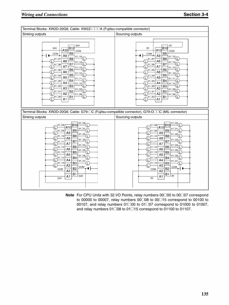
Wiring and Connections Section 3-4
Note For CPU Units with 32 I/O Points, relay numbers 00@00 to 00@07 correspondto 00000 to 00007, relay numbers 00@08 to 00@15 correspond to 00100 to00107, and relay numbers 01@00 to 01@07 correspond to 01000 to 01007,and relay numbers 01@08 to 01@15 correspond to 01100 to 01107.
Terminal Blocks: XW2D-20G6; Cable: XW2Z-@@@A (Fujitsu-compatible connector)
Sinking outputs Sourcing outputs
Terminal Blocks: XW2D-20G6; Cable: G79-@C (Fujitsu-compatible connector), G79-O@@C (MIL connector)
Sinking outputs Sourcing outputs
135

Wiring and Connections Section 3-4
Terminal Blocks: XW2C-20G6-IO16; Cable: XW2Z-@@@A (Fujitsu-compatible connector)
Sinking outputs Sourcing outputs
A10B10
A10B10
136

Wiring and Connections Section 3-4
Relay Terminal: G7TC-OC08 Relay Terminal: G7TC-OC16 Relay Terminal: G7TC-OC16-1Cable: G79-@C (Fujitsu), G79-O@@C (MIL) (See note.)
Cable: G79-@C (Fujitsu), G79-O@@C (MIL) (See note.)
Cable: G79-@C (Fujitsu), G79-O@@C (MIL) (See note.)
Relay Terminals: G70D-SOC16, G70D-FOM16 Relay Terminal: G70D-SOC16-1, G70D-FOM16-1Cable: G79-@C (Fujitsu), G79-O@@C (MIL) (See note.) Cable: G79-I@@C (MIL) (See note.)
Sinking outputs onlyPower supply
Sinking outputs only
Power supply
Sourcing outputs onlyPower supply
Sinking outputs only
Power supply
Power supply
Power supply
Power supply
Power supply
Power supply
Power supply
Power supply
Sourcing outputs only
Power supply
Power supply
Power supply
Power supply
Power supply
Power supply
Power supply
Power supply
137
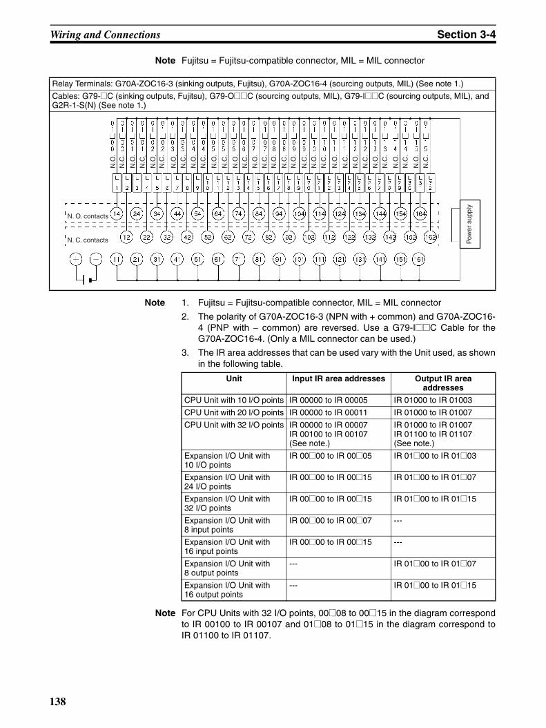
Wiring and Connections Section 3-4
Note Fujitsu = Fujitsu-compatible connector, MIL = MIL connector
Note 1. Fujitsu = Fujitsu-compatible connector, MIL = MIL connector
2. The polarity of G70A-ZOC16-3 (NPN with + common) and G70A-ZOC16-4 (PNP with − common) are reversed. Use a G79-I@@C Cable for theG70A-ZOC16-4. (Only a MIL connector can be used.)
3. The IR area addresses that can be used vary with the Unit used, as shownin the following table.
Note For CPU Units with 32 I/O points, 00@08 to 00@15 in the diagram correspondto IR 00100 to IR 00107 and 01@08 to 01@15 in the diagram correspond toIR 01100 to IR 01107.
Relay Terminals: G70A-ZOC16-3 (sinking outputs, Fujitsu), G70A-ZOC16-4 (sourcing outputs, MIL) (See note 1.)
Cables: G79-@C (sinking outputs, Fujitsu), G79-O@@C (sourcing outputs, MIL), G79-I@@C (sourcing outputs, MIL), and G2R-1-S(N) (See note 1.)
N. O. contacts
N. C. contacts Pow
er s
uppl
y
N.O
.N
.C.
N.O
.
N.C
.
N.O
.N
.C.
N.O
.N
.C.
N.O
.
N.C
.
N.O
.
N.C
.
N.O
.
N.C
.
N.O
.
N.C
.
N.O
.
N.C
.
N.O
.
N.O
.
N.C
.
N.O
.
N.C
.
N.C
.
N.C
.N
.O.
N.C
.
N.C
.
N.O
.
N.C
.
N.O
.
N.O
.
Unit Input IR area addresses Output IR area addresses
CPU Unit with 10 I/O points IR 00000 to IR 00005 IR 01000 to IR 01003
CPU Unit with 20 I/O points IR 00000 to IR 00011 IR 01000 to IR 01007
CPU Unit with 32 I/O points IR 00000 to IR 00007IR 00100 to IR 00107 (See note.)
IR 01000 to IR 01007IR 01100 to IR 01107 (See note.)
Expansion I/O Unit with 10 I/O points
IR 00@00 to IR 00@05 IR 01@00 to IR 01@03
Expansion I/O Unit with 24 I/O points
IR 00@00 to IR 00@15 IR 01@00 to IR 01@07
Expansion I/O Unit with 32 I/O points
IR 00@00 to IR 00@15 IR 01@00 to IR 01@15
Expansion I/O Unit with 8 input points
IR 00@00 to IR 00@07 ---
Expansion I/O Unit with 16 input points
IR 00@00 to IR 00@15 ---
Expansion I/O Unit with 8 output points
--- IR 01@00 to IR 01@07
Expansion I/O Unit with 16 output points
--- IR 01@00 to IR 01@15
138

Wiring and Connections Section 3-4
Using Pulse Outputs The following diagrams show example applications of sink-type transistor out-puts using output bits IR 01000 and IR 01001. Use the PULS(65), SPED(−−),ACC(−−), PWM(−−), and SYNC(−−) instructions to produce pulse outputs(rather than normal outputs) from output bits IR 01000 and IR 01001.
Note *CW is clockwise and CCW is counter-clockwise.
Output Wiring Precautions
Observe the following precautions to protect the PC’s internal components.
Output Short Protection
The output or internal circuitry might be damaged when the load connected toan output is short-circuited, so it is recommended to install a protective fuse ineach output circuit. Use a fuse that has a capacity of about twice the outputratings.
CPM2C
Single-phase pulse output(Fixed duty ratio)
Motor driver
Pulse output 0: 01000
CPM2C
Pulse output 1: 01001
COM
Motor driver
Single-phase pulse output(Variable duty ratio)
Relay
Pulse output 0: 01000
CPM2C
Pulse output 1: 01001
COM
Relay
Pulse plus direction output
Motor driver
Pulse output 0: 01000
CPM2C
Direction output: 01001
COM
Directioninput
Increment pulse output
Motor driver
CW* pulse output: 01000
CCW* pulse output: 01001
COM
CW input
CCW input
24 V 24 V
24 V 24 V
139
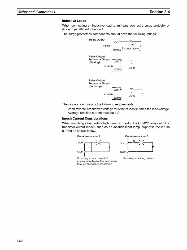
Wiring and Connections Section 3-4
Inductive Loads
When connecting an inductive load to an input, connect a surge protector ordiode in parallel with the load.
The surge protector’s components should have the following ratings:
The diode should satisfy the following requirements:
Peak reverse-breakdown voltage must be at least 3 times the load voltage.Average rectified current must be 1 A.
Inrush Current Considerations
When switching a load with a high inrush current in the CPM2C relay output ortransistor output model, such as an incandescent lamp, suppress the inrushcurrent as shown below.
OUT
COM
CPM2CSurge protector
Relay Output
OUT
COMCPM2C
Diode
Relay OutputTransistor Output(Sinking)
OUT
COM
CPM2CDiode
Relay OutputTransistor Output(Sourcing)
R
R
Countermeasure 1
Providing a dark current of approx. one-third of the rated value through an incandescent lamp
Countermeasure 2
Providing a limiting resistor
OUT
COM
OUT
COM
140

Wiring and Connections Section 3-4
3-4-9 RS-422 Port ConnectionWhen using the RS-422/RS-232C Adapter Unit (CPM2C-CIF11) in a HostLink connection (1:N), wire the RS-422 port as shown below.
Note Turn ON the terminating resistance in the last Unit for stable communications.
Host
RS-232C
B500-AL004 CPM2C-CIF11
RS-422
CPM2C-CIF11
NT-AL001
FG 7
3
6
1
9
5
SG
RDA
RDB
SDA
SDB
1
2
3
45
RDA
RDB
SDA
SDBNC
1
2
3
4
5
RDA
RDB
SDA
SDB
NC
HostRS-232C
CPM2C-CIF11
RS-422
CPM2C-CIF11
FG
4
3
6
5
7
8
SG
RDA
RDB
CSB
CSA
1
2
3
4
5
RDA
RDB
SDA
SDB
NC
1
2
3
4
5
RDA
RDB
SDA
SDB
NC
1
2
SDA
SDB
141

Wiring and Connections Section 3-4
3-4-10 Programming Device ConnectionsProgramming Console Use one of the connecting cables shown in the following diagram to connect a
Programming Console to the CPM2C.
Note When connecting a Programming Console to the peripheral port of theCPM2C-CIF01-V1 Peripheral/RS-232C Adapter Unit, turn OFF the cableswitch (SW1).
Peripheral portCPM2C CPU Unit
CS1W-CN114 (0.05 m)
Main cable (2 m)
CQM1-PRO01-E(with attached 2-m cable)
C200H-PRO27-E
C200H-CN222 (2 m)C200H-CN422 (4 m)
CS1W-CN224 (2 m)CS1W-CN624 (6 m)
CPM2C-CN111 (0.15 m)
CQM1H-PRO01-E(with attached 2-m cable) Main cable (2 m)
CPM2C-CIF01-V1
142

Wiring and Connections Section 3-4
Connections for the CX-Programmer
The CPM2C is supported by CX-Programmer version 2.1 or higher. Either thetool bus (peripheral) or SYSMAC WAY (Host Link) can be used for communi-cations.
Connecting to the Peripheral Port
With a peripheral port connection, communications are possible by selectingeither the tool bus or SYSMAC WAY as the CX-Programmer's network type(i.e., serial communications mode).
Note 1. The CS1W-CN226/CN626 can be connected to the CPU Unit, but theycannot be connected to the CPM2C-CIF01-V1. Also, they cannot be usedfor tool bus communications. The CS1W-CN226/CN626 can be connectedto the CPM2C-CIF01-V1, however, if pin 1 on the front-panel DIP switch isturned ON.
2. The CS1W-CN226/CN626 cannot be connected to the CPM2C-CIF01.
3. The CS1W-CN225/CN625/CN227/CN627 cannot be used.
4. The CQM1-CIF11 cannot be used. If it is connected, the CPM2C will notdetect a tool connection and, with the default PC Setup settings (i.e., oper-ation at startup determined by tool connection), the CPM2C will start op-eration in RUN mode.
IBM PC/AT or compatible computer
Connecting Cable CS1W-CN226 (2 m) (See note 1.) CS1W-CN626 (6 m) (See note 1.)
Connecting Cable CQM1-CIF02 (3.3 m)
Peripheral port
Connecting Cable CPM2C-CN111 (0.15 m)
Connecting Cable CS1W-CN114 (0.05 m)
CPM2C CPU Unit
CPM2C-CIF01-V1
143

Wiring and Connections Section 3-4
Connecting to the RS-232C Port
With an RS-232C port connection, communications are possible by usingSYSMAC WAY as the CX-Programmer's network type (i.e., serial communica-tions mode). Tool bus communications are not possible.
IBM PC/AT or compatible computer
Connecting Cable XW2Z-200S-V (2 m) XW2Z-500S-V (5 m)
RS-232C port (D-sub 9-pin)
Connecting Cable CPM2C-CN111 (0.15 m)
Connecting Cable CS1W-CN118 (0.1 m)
CPM2C CPU Unit
CPM2C-CIF01-V1
CPM2C-CIF11
CPM2C-CIF21
144
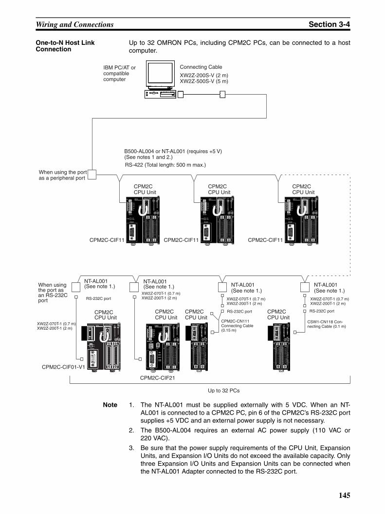
Wiring and Connections Section 3-4
One-to-N Host Link Connection
Up to 32 OMRON PCs, including CPM2C PCs, can be connected to a hostcomputer.
Note 1. The NT-AL001 must be supplied externally with 5 VDC. When an NT-AL001 is connected to a CPM2C PC, pin 6 of the CPM2C’s RS-232C portsupplies +5 VDC and an external power supply is not necessary.
2. The B500-AL004 requires an external AC power supply (110 VAC or220 VAC).
3. Be sure that the power supply requirements of the CPU Unit, ExpansionUnits, and Expansion I/O Units do not exceed the available capacity. Onlythree Expansion I/O Units and Expansion Units can be connected whenthe NT-AL001 Adapter connected to the RS-232C port.
Connecting Cable
XW2Z-200S-V (2 m)XW2Z-500S-V (5 m)
IBM PC/AT or compatible computer
B500-AL004 or NT-AL001 (requires +5 V)(See notes 1 and 2.)
RS-422 (Total length: 500 m max.)When using the port as a peripheral port
CPM2CCPU Unit
CPM2C CPM2CCPU Unit
CPM2C-CIF11
When using the port as an RS-232C port
NT-AL001(See note 1.) NT-AL001
(See note 1.)NT-AL001(See note 1.)
RS-232C port
XW2Z-070T-1 (0.7 m)XW2Z-200T-1 (2 m)
XW2Z-070T-1 (0.7 m)XW2Z-200T-1 (2 m)
RS-232C port
CPM2C-CN111 Connecting Cable (0.15 m)
Up to 32 PCs
XW2Z-070T-1 (0.7 m)XW2Z-200T-1 (2 m)
RS-232C port
CSW1-CN118 Con-necting Cable (0.1 m)
CPM2CCPU Unit
CPM2C-CIF11
CPM2CCPU Unit
CPM2C-CIF11
CPM2CCPU Unit
CPM2C-CIF21
CPM2CCPU Unit
NT-AL001(See note 1.)
XW2Z-070T-1 (0.7 m)XW2Z-200T-1 (2 m)
CPM2C-CIF01-V1
CPU Unit
145

Wiring and Connections Section 3-4
3-4-11 No-Protocol CommunicationsThe TXD(48) and RXD(47) instructions can be used in no-protocol mode toexchange data with standard serial devices. For example, data can bereceived from a bar code reader or transmitted to a serial printer. The serialdevices can be connected to the communications port as a RS-232C port orperipheral port, as shown in the following diagrams.
Note See One-to-one Computer Connections on page 142 for details on the sys-tem configurations that can be assembled for serial communications.
CPM2C CPU Unit
RS-232C devices
Bar code reader Serial printer Other serial device
CPM2C-CIF21
CPM2C-CIF01-V1
CPM2C-CIF11
146

Wiring and Connections Section 3-4
3-4-12 OMRON PT ConnectionsIn a 1:1 NT Link, a CPM2C can be connected directly to a Programmable Ter-minal. The direct connection with a Programmable Terminal is possible byusing the communications as a RS-232C port only (not as a peripheral port).
A Programmable Terminal can also be connected by a Host Link connection.Either the RS-232C port or peripheral port connection can be used for theHost Link.
Note The Programmable Terminal cannot be connected using a peripheral portconnection when communicating via an NT Link.
Connecting CableXW2Z-200T (2 m)XW2Z-500T (5 m)
NT-AL001RS-232C Adapter
CPM2C-CN111 (0.15 m)
XW2Z-070T-1 (0.7 m)XW2Z-200T-1 (2 m)
CS1W-CN118 (0.1 m)
CPM2C CPU Unit
OMRON Programmable Terminal
RS-232C port (D-sub 9-pin)
RS-232C port
RS-232C peripheral port
RS-422 peripheral port
RS-232C port
CPM2C-CIF11
RS-232C connection
RS-422 connection
CPM2C-CIF21
RS-232C port
t
CPM2C-CIF01-V1
RS-232C por
147
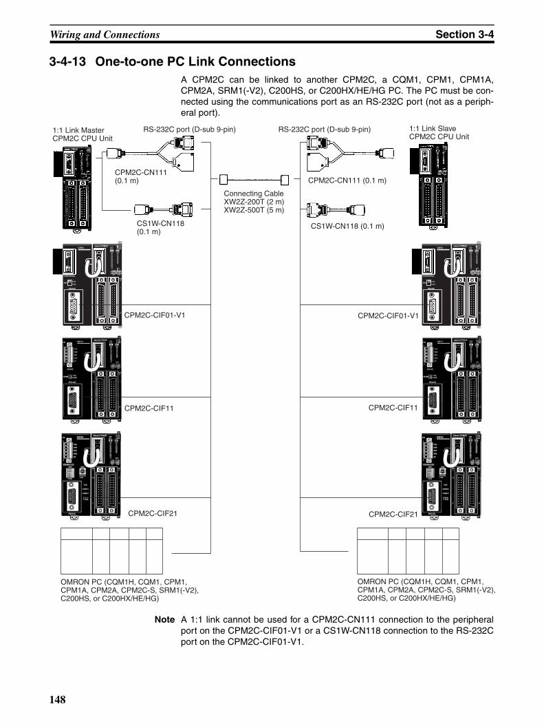
Wiring and Connections Section 3-4
3-4-13 One-to-one PC Link ConnectionsA CPM2C can be linked to another CPM2C, a CQM1, CPM1, CPM1A,CPM2A, SRM1(-V2), C200HS, or C200HX/HE/HG PC. The PC must be con-nected using the communications port as an RS-232C port (not as a periph-eral port).
Note A 1:1 link cannot be used for a CPM2C-CN111 connection to the peripheralport on the CPM2C-CIF01-V1 or a CS1W-CN118 connection to the RS-232Cport on the CPM2C-CIF01-V1.
CPM2C-CN111 (0.1 m)
CS1W-CN118 (0.1 m)
CS1W-CN118 (0.1 m)
1:1 Link Master CPM2C CPU Unit
Connecting CableXW2Z-200T (2 m)XW2Z-500T (5 m)
RS-232C port (D-sub 9-pin)
CPM2C-CN111 (0.1 m)
RS-232C port (D-sub 9-pin) 1:1 Link Slave CPM2C CPU Unit
OMRON PC (CQM1H, CQM1, CPM1, CPM1A, CPM2A, CPM2C-S, SRM1(-V2), C200HS, or C200HX/HE/HG)
OMRON PC (CQM1H, CQM1, CPM1, CPM1A, CPM2A, CPM2C-S, SRM1(-V2), C200HS, or C200HX/HE/HG)
CPM2C-CIF01-V1
CPM2C-CIF11
CPM2C-CIF01-V1
CPM2C-CIF11
CPM2C-CIF21 CPM2C-CIF21
148

Wiring and Connections Section 3-4
3-4-14 CompoBus/S I/O Link ConnectionsA CompoBus/S I/O Link can be used to create an I/O link (remote I/O) of 8input points and 8 output points with a CompoBus/S Master Unit or SRM1 PC.The connection is made through a CompoBus/S I/O Link Unit.
From the standpoint of the CPM2C CPU Unit, the area allocated to the Com-poBus/S I/O Link Unit can be treated just like the area allocated to an Expan-sion I/O Unit. The difference is that the bits are not actual I/O points, but I/Obits in the Master Unit.
Cables
Use special flat cable or VCTF cable to connect the nodes in the CompoBus/S I/O Link. (Special flat cables and VCTF cables cannot be combined in thesame system.)
CPM2C CPU Unit
CompoBus/S Master Unit (or SRM1 PC)
C200HX/HG/HE PC
CompoBus/S I/O Link Unit(Slave)
Name Specifications
Flat cable 4-core flat cable, 0.75 mm2
VCTF cable 2-core x 0.75 mm2
149

SECTION 4Using a Programming Console
This section outlines the operations possible with the Programming Consoles. Actual CPT operating procedures areprovided in the CPT User Manual. Operations for the WS02-CXPC1-E CX-Programmer are provided in the WS02-CXPC1-E CX-Programmer Operation Manual (W437).Refer to 3-4-10 Programming Device Connections and 4-1-1 Connecting the Programming Console for details onconnecting a Programming Console or personal computer to the CPM2C.
4-1 Using a Programming Console. . . . . . . . . . . . . . . . . . . . . . . . . . . . . . . . . . . . 1524-1-1 Connecting the Programming Console . . . . . . . . . . . . . . . . . . . . . . 1524-1-2 Compatible Programming Consoles . . . . . . . . . . . . . . . . . . . . . . . . 1544-1-3 Changing the CPM2C’s Mode with the Mode Switch. . . . . . . . . . . 1574-1-4 Preparation for Operation. . . . . . . . . . . . . . . . . . . . . . . . . . . . . . . . . 1584-1-5 Entering the Password . . . . . . . . . . . . . . . . . . . . . . . . . . . . . . . . . . . 159
4-2 Programming Console Operations . . . . . . . . . . . . . . . . . . . . . . . . . . . . . . . . . 1604-2-1 Overview . . . . . . . . . . . . . . . . . . . . . . . . . . . . . . . . . . . . . . . . . . . . . 1604-2-2 Clearing Memory . . . . . . . . . . . . . . . . . . . . . . . . . . . . . . . . . . . . . . . 1614-2-3 Memory All Clear . . . . . . . . . . . . . . . . . . . . . . . . . . . . . . . . . . . . . . 1624-2-4 UM Allocation Information Read . . . . . . . . . . . . . . . . . . . . . . . . . . 1624-2-5 Reading/Clearing Error Messages . . . . . . . . . . . . . . . . . . . . . . . . . . 1634-2-6 Buzzer Operation . . . . . . . . . . . . . . . . . . . . . . . . . . . . . . . . . . . . . . . 1634-2-7 Assigning Expansion Instruction Function Codes . . . . . . . . . . . . . . 1644-2-8 Setting and Reading a Program Memory Address and Monitoring
I/O Bit Status . . . . . . . . . . . . . . . . . . . . . . . . . . . . . . . . . . . . . . . . . . 1654-2-9 Entering or Editing Programs . . . . . . . . . . . . . . . . . . . . . . . . . . . . . 1654-2-10 Instruction Search . . . . . . . . . . . . . . . . . . . . . . . . . . . . . . . . . . . . . . 1684-2-11 Bit Operand Search . . . . . . . . . . . . . . . . . . . . . . . . . . . . . . . . . . . . . 1694-2-12 Inserting and Deleting Instructions . . . . . . . . . . . . . . . . . . . . . . . . . 1704-2-13 Checking the Program . . . . . . . . . . . . . . . . . . . . . . . . . . . . . . . . . . . 1714-2-14 Bit, Digit, Word Monitor . . . . . . . . . . . . . . . . . . . . . . . . . . . . . . . . . 1724-2-15 Differentiation Monitor . . . . . . . . . . . . . . . . . . . . . . . . . . . . . . . . . . 1744-2-16 Binary Monitor. . . . . . . . . . . . . . . . . . . . . . . . . . . . . . . . . . . . . . . . . 1744-2-17 Three-Word Monitor . . . . . . . . . . . . . . . . . . . . . . . . . . . . . . . . . . . . 1754-2-18 Signed Decimal Monitor . . . . . . . . . . . . . . . . . . . . . . . . . . . . . . . . . 1764-2-19 Unsigned Decimal Monitor . . . . . . . . . . . . . . . . . . . . . . . . . . . . . . . 1764-2-20 Three-Word Data Modification . . . . . . . . . . . . . . . . . . . . . . . . . . . . 1774-2-21 Changing Timer, Counter SV. . . . . . . . . . . . . . . . . . . . . . . . . . . . . . 1774-2-22 Hexadecimal, BCD Data Modification . . . . . . . . . . . . . . . . . . . . . . 1784-2-23 Binary Data Modification . . . . . . . . . . . . . . . . . . . . . . . . . . . . . . . . 1794-2-24 Signed Decimal Data Modification . . . . . . . . . . . . . . . . . . . . . . . . . 1804-2-25 Unsigned Decimal Data Modification . . . . . . . . . . . . . . . . . . . . . . . 1814-2-26 Force Set, Reset . . . . . . . . . . . . . . . . . . . . . . . . . . . . . . . . . . . . . . . . 1814-2-27 Clear Force Set/Reset. . . . . . . . . . . . . . . . . . . . . . . . . . . . . . . . . . . . 1824-2-28 Hex-ASCII Display Change. . . . . . . . . . . . . . . . . . . . . . . . . . . . . . . 1834-2-29 Displaying the Cycle Time. . . . . . . . . . . . . . . . . . . . . . . . . . . . . . . . 1834-2-30 Reading and Setting the Clock. . . . . . . . . . . . . . . . . . . . . . . . . . . . . 184
4-3 Programming Example. . . . . . . . . . . . . . . . . . . . . . . . . . . . . . . . . . . . . . . . . . 1854-3-1 Preparatory Operations . . . . . . . . . . . . . . . . . . . . . . . . . . . . . . . . . . 1854-3-2 Example Program. . . . . . . . . . . . . . . . . . . . . . . . . . . . . . . . . . . . . . . 1864-3-3 Programming Procedures . . . . . . . . . . . . . . . . . . . . . . . . . . . . . . . . . 1874-3-4 Checking the Program . . . . . . . . . . . . . . . . . . . . . . . . . . . . . . . . . . . 1904-3-5 Test Run in MONITOR Mode . . . . . . . . . . . . . . . . . . . . . . . . . . . . . 190
151

Using a Programming Console Section 4-1
4-1 Using a Programming ConsoleThis section provides information on connecting and using a ProgrammingConsole. Refer to 5-3 Programming Console Operation Errors for details onerrors that might occur during Programming Console operations.
4-1-1 Connecting the Programming ConsoleA Programming Console can be connected to the CPM2C’s communicationsport or the peripheral port on a CPM2C-CN111 Connecting Cable; it cannotbe connected to the CPM2C-CN111 Connecting Cable’s RS-232C port.
Note The setting of SW2 will affect the startup operating mode for all Units with lotnumbers of 3180O (31 August 2000) or earlier. Refer to 1-7 Changes in SW2for details.
a) With CPU Units with lot numbers of 3180O or earlier, before connect-ing the Programming Console, turn OFF Communications Switch(SW2) on the front of the CPM2C CPU Unit. The PRO indicator willlight.
b) If SW2 is turned OFF for a Programming Console connection, a PTcannot be used in PT Programming Console Mode connected to theRS-232C port. Turn ON SW2 to specify that a Programming Consolewill not be connected before attempting to use PT Programming Con-sole Mode for the RS-232C port.
c) Do not change the setting of SW2 when a Programming Console,CPM2C-CIF01-V1, CPM2C-CIF11, CQM1-CIF01, or CQM1-CIF02 isconnected. Communications will be disconnected if the switch settingis changed, causing a communications error or causing the Program-ming Console not to respond (i.e., the display will not change whenkeys are pressed).
Communications Switch
Communications Switches
PRO
ON ON
SW1 SW2
152
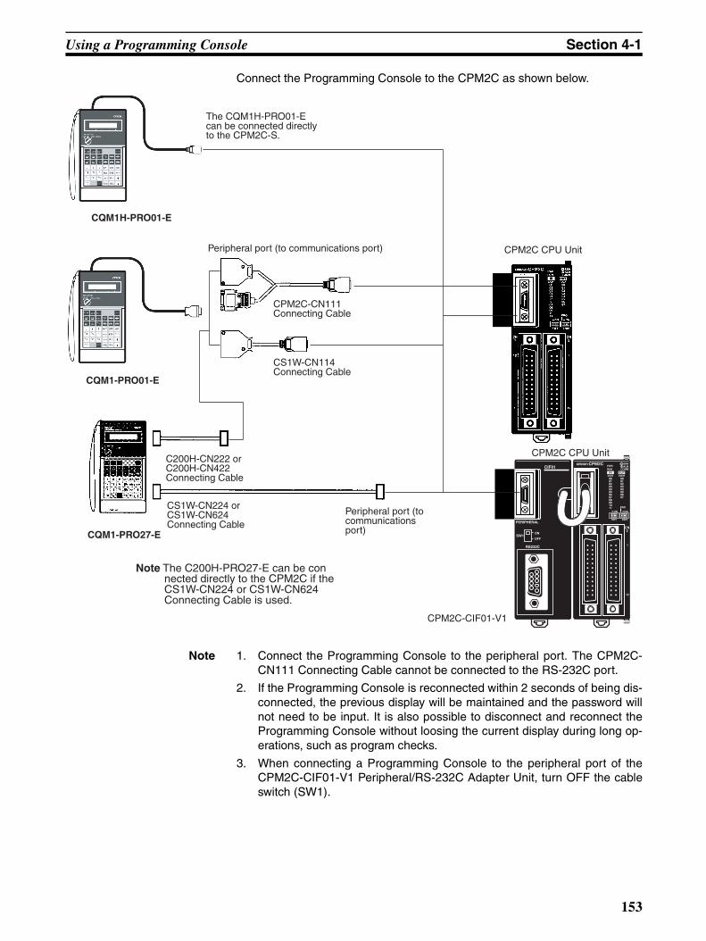
Using a Programming Console Section 4-1
Connect the Programming Console to the CPM2C as shown below.
Note 1. Connect the Programming Console to the peripheral port. The CPM2C-CN111 Connecting Cable cannot be connected to the RS-232C port.
2. If the Programming Console is reconnected within 2 seconds of being dis-connected, the previous display will be maintained and the password willnot need to be input. It is also possible to disconnect and reconnect theProgramming Console without loosing the current display during long op-erations, such as program checks.
3. When connecting a Programming Console to the peripheral port of theCPM2C-CIF01-V1 Peripheral/RS-232C Adapter Unit, turn OFF the cableswitch (SW1).
Peripheral port (to communications port) CPM2C CPU Unit
CPM2C-CN111 Connecting Cable
CS1W-CN114 Connecting Cable
CQM1-PRO01-E
CS1W-CN224 or CS1W-CN624 Connecting Cable
CQM1-PRO27-E
C200H-CN222 or C200H-CN422 Connecting Cable
Peripheral port (to communications port)
Note The C200H-PRO27-E can be connected directly to the CPM2C if the CS1W-CN224 or CS1W-CN624 Connecting Cable is used.
CQM1H-PRO01-E
The CQM1H-PRO01-E can be connected directly to the CPM2C-S.
CPM2C CPU Unit
CPM2C-CIF01-V1
153

Using a Programming Console Section 4-1
Panel Installation The C200H-PRO27-E Programming Console can be installed in a controlpanel as shown in the following diagram. (The C200H-ATT01 MountingBracket is sold separately.)
Allow at least 80 mm for the cable connector above the Programming Con-sole.
4-1-2 Compatible Programming ConsolesThere are three Programming Consoles that can be used with the CPM2C:The CQM1H-PRO01-E, the CQM1-PRO01-E, and the C200H-PRO27-E. Thekey functions for these Programming Consoles are identical.
186+1.1−0
92+0.8−0
Mounting Bracket
Two screws
Panel thickness: 1.0 to 3.2 mm
Mounting hole dimensions (DIN43700 standards)
About 70 mm is required.
At least 80 mm is required.
Either connector may be used.
37
15
154

Using a Programming Console Section 4-1
Press and hold the Shift Key to input a letter shown in the upper-left corner ofthe key or the upper function of a key that has two functions. For example, theCQM1-PRO01-E’s AR/HR Key can specify either the AR or HR Area; pressand release the Shift Key and then press the AR/HR Key to specify the ARArea.
LCD display
Mode switch
Operation keys
Attached ConnectingCable (2 m)
The CQM1H-PRO01-E can be connected directly to the CPM2C.
CQM1-PRO01-ECQM1H-PRO01-E
Attached ConnectingCable (2 m)
SHIFT
CHG SRCH
MONTRDELSET
RESET INS
WRITEVERCLR
CONT
#
Cassette recorded jack (Cannot be used with the CPM2C).
Connecting Cables
C200H-CN222 (2 m)C200H-CN422 (4 m)CS1W-CN224 (2 m)CS1W-CN624 (6 m)
LCD display
Mode switch
Operation keys
C200H-PRO27-E
155

Using a Programming Console Section 4-1
Different Keys The following keys are labeled differently on the CQM1-PRO01-E and theC200H-PRO27-E, but the operation of the keys in each pair is identical.
Note To specify the AR area, use SHIFT and HR Keys for the C200H-PRO27-E anduse SHIFT and AR/HR Keys for the CQM1-PRO01-E.
A shift symbol will be displayed in the upper-right corner of the screen whenthe Shift Key is pressed. The shift input can be cleared by pressing the ShiftKey again.
Mode Switch The mode switch controls the CPM2C’s operating mode. The key can beremoved when the switch is set to RUN or MONITOR but it cannot beremoved when the switch is set to PROGRAM.
Contrast Control The display contrast can be adjusted with the control on the right side of theProgramming Console.
Buzzer Volume The C200H-PRO27-E’s buzzer volume can be adjusted with the lever on theright side of the Programming Console. The CQM1-PRO01-E’s buzzer vol-ume cannot be adjusted.
Note The buzzer volume can be turned on and off with a key operation. See 4-2-6Buzzer Operation for details.
CQM1-PRO01-E Keys C200H-PRO27-E Keys
AR
HRHR
SET PLAY
SET
RESET REC
RESET
Shift inputsymbol
SHIFT
Contrast control
Low volume
High volume
C200H-PRO27-E
156

Using a Programming Console Section 4-1
4-1-3 Changing the CPM2C’s Mode with the Mode SwitchOnce the Programming Console has been connected, its mode switch can beused to change the CPM2C’s operating mode. The mode display (<PRO-GRAM>, <MONITOR>, or <RUN>) will appear on the Programming Consolescreen.
• No key operations can be performed while the mode display is displayedon the Programming Console screen. Press CLR to clear the display sothat key operations can be performed.
• If the SHIFT Key is pressed while the mode switch is turned, the originaldisplay will remain on the Programming Console’s screen and the modedisplay won’t appear.
• The CPM2C will enter RUN mode automatically if a Programming Con-sole isn’t connected when the CPM2C is turned on.
Operating Modes
PROGRAM Mode
The CPM2C program isn’t executed in PROGRAM mode. Use PROGRAMmode to create and edit the program, clear memory, or check the program forerrors.
MONITOR Mode
The CPM2C program is executed in MONITOR mode and I/O is processedjust as it is in RUN mode. Use MONITOR mode to test system operations,such as monitoring CPM2C operating status, force-setting and resetting I/Obits, changing the SV/PV of timers and counters, changing word data, andonline editing.
RUN Mode
This is the CPM2C’s normal operating mode. The CPM2C’s operating statuscan be monitored from a Programming Device, but bits can’t be force-set/force-reset and the SV/PV of timers and counters can’t be changed.
!Caution Check the system thoroughly before changing the operating mode of the PCto prevent any accidents that might occur when the program is first started.
!Caution Never change the mode while pressing any of the keys.
Mode display
Initial display
CLR SHIFT CLR
RUNMONITOR
PROGRAM RUNMONITOR
PROGRAMRUNMONITOR
PROGRAM
Operation Operation
157
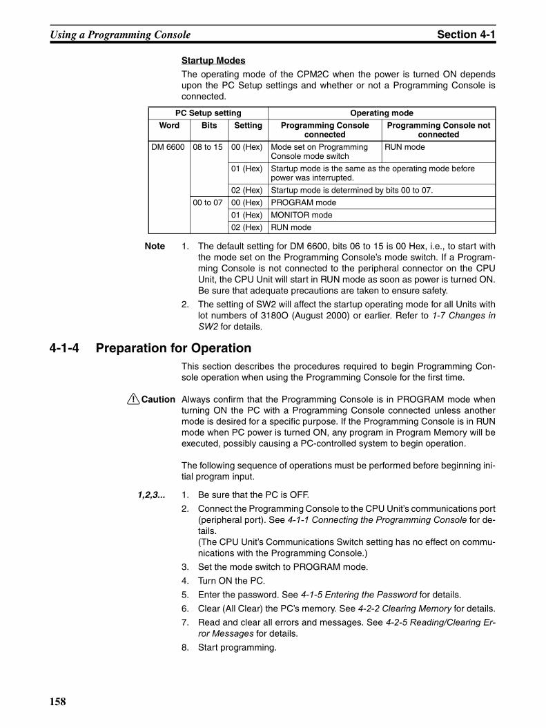
Using a Programming Console Section 4-1
Startup Modes
The operating mode of the CPM2C when the power is turned ON dependsupon the PC Setup settings and whether or not a Programming Console isconnected.
Note 1. The default setting for DM 6600, bits 06 to 15 is 00 Hex, i.e., to start withthe mode set on the Programming Console’s mode switch. If a Program-ming Console is not connected to the peripheral connector on the CPUUnit, the CPU Unit will start in RUN mode as soon as power is turned ON.Be sure that adequate precautions are taken to ensure safety.
2. The setting of SW2 will affect the startup operating mode for all Units withlot numbers of 3180O (August 2000) or earlier. Refer to 1-7 Changes inSW2 for details.
4-1-4 Preparation for OperationThis section describes the procedures required to begin Programming Con-sole operation when using the Programming Console for the first time.
!Caution Always confirm that the Programming Console is in PROGRAM mode whenturning ON the PC with a Programming Console connected unless anothermode is desired for a specific purpose. If the Programming Console is in RUNmode when PC power is turned ON, any program in Program Memory will beexecuted, possibly causing a PC-controlled system to begin operation.
The following sequence of operations must be performed before beginning ini-tial program input.
1,2,3... 1. Be sure that the PC is OFF.
2. Connect the Programming Console to the CPU Unit’s communications port(peripheral port). See 4-1-1 Connecting the Programming Console for de-tails.(The CPU Unit’s Communications Switch setting has no effect on commu-nications with the Programming Console.)
3. Set the mode switch to PROGRAM mode.
4. Turn ON the PC.
5. Enter the password. See 4-1-5 Entering the Password for details.
6. Clear (All Clear) the PC’s memory. See 4-2-2 Clearing Memory for details.
7. Read and clear all errors and messages. See 4-2-5 Reading/Clearing Er-ror Messages for details.
8. Start programming.
PC Setup setting Operating mode
Word Bits Setting Programming Console connected
Programming Console not connected
DM 6600 08 to 15 00 (Hex) Mode set on Programming Console mode switch
RUN mode
01 (Hex) Startup mode is the same as the operating mode before power was interrupted.
02 (Hex) Startup mode is determined by bits 00 to 07.
00 to 07 00 (Hex) PROGRAM mode
01 (Hex) MONITOR mode
02 (Hex) RUN mode
158

Using a Programming Console Section 4-1
4-1-5 Entering the PasswordTo gain access to the PC’s programming functions, you must first enter thepassword. The password prevents unauthorized access to the program.
The PC prompts you for a password when PC power is turned on or, if PCpower is already on, after the Programming Console has been connected tothe PC. To gain access to the system when the “Password!” messageappears, press CLR and then MONTR. Then press CLR to clear the display.
If the Programming Console is connected to the PC when PC power isalready on, the first display below will indicate the mode the PC was in beforethe Programming Console was connected. Ensure that the PC is in PRO-GRAM mode before you enter the password. When the password isentered, the PC will shift to the mode set on the mode switch, causing PCoperation to begin if the mode is set to RUN or MONITOR. The mode can bechanged to RUN or MONITOR with the mode switch after entering the pass-word.
Indicates the mode set by the mode selector switch.
CLR
MONTR
159

Programming Console Operations Section 4-2
4-2 Programming Console Operations
4-2-1 OverviewThe following table lists the programming and monitoring operations that canbe performed from a Programming Console. Refer to the rest of this sectionfor details on operational procedures.
Name Function Page
Clearing memory Clears all or part of the Program Memory and any data areas that are not read-only, as well as the contents of the Programming Console’s memory.
161
Memory all clear Clears all of the user program, PC Setup, I/O memory area, timer/counter, and DM area data, including the I/O comment area set from the CX-Pro-grammer (Ver. 2.0 or higher).
162
UM allocation information read
When an I/O comment area has been set from the CX-Programmer (Ver. 2.0 or higher), reads the I/O comment area and ladder program area sizes.
162
Reading/clearing error mes-sages
Displays and clears error messages and displays MESSAGE instruction messages.
163
Buzzer operation Turns on and off the buzzer that sounds when Programming Console keys are pressed.
163
Assigning expansion instruc-tion function codes
Reads or changes the function codes assigned to expansion instructions 164
Setting a program memory address
Sets the specified program memory address when reading, writing, insert-ing and deleting programs.
165
Reading a program memory address
Reads the contents of the Program Memory. Displays the status of the cur-rently displayed bit in PROGRAM and MONITOR modes.
165
Instruction search Finds occurrences of the specified instruction in the program. 168
Bit operand search Finds occurrences of the specified operand bit in the program. 169
Inserting and deleting instruc-tions
Inserts or deletes instructions from the program. 170
Entering or editing programs Overwrites the contents of the current Program Memory to either input a program for the first time or to change a program that already exists.
165
Checking the program Checks for programming errors and displays the program address and error when errors are found.
171
Bit, digit, word monitor Monitors the status of up to 16 bits and words, although only 3 can be shown on the display at one time.
172
Multiple address monitor Monitors the status of up to 6 bits and words simultaneously. 173
Differentiation monitor Monitors the up or down differentiation status of a particular bit. 174
Binary monitor Monitors the ON/OFF status of any word’s 16 bits. 174
3-word monitor Monitors the status of three consecutive words. 175
Signed decimal monitor Converts the contents of the specified word from signed hexadecimal (two’s complement format) to signed decimal for display.
176
Unsigned decimal monitor Converts hexadecimal data in a word to unsigned decimal for display. 176
3-word data modification Changes the contents of one or more of the 3 consecutive words displayed in the 3-Word Monitor operation.
177
Changing timer, counter SV 1 Changes the SV of a timer or counter. 177
Changing timer, counter SV 2 Makes fine adjustment changes to the SV of the timer or counter. 178
Hexadecimal, BCD data modi-fication
Changes the BCD or hexadecimal value of a word being monitored. 178
Binary data modification Changes the status of a word’s bits when the word is being monitored. 179
Signed decimal data modifica-tion
Changes the decimal value of a word being monitored as signed decimal data, within a range of –32,768 to 32,767. The contents of the specified word are converted automatically to signed hexadecimal (two’s complement format.)
180
160

Programming Console Operations Section 4-2
4-2-2 Clearing MemoryThis operation is used to clear all or part of the Program Memory and dataareas, as well as the contents of the Programming Console’s memory. Thisoperation is possible in PROGRAM mode only.
Before beginning to program for the first time or when installing a new pro-gram, clear all areas.
All Clear The following procedure is used to clear memory completely, including theprogram, all data areas, counter PVs, Data Memory, and the PC Setup (DM6600 to DM 6655).
1,2,3... 1. Bring up the initial display by pressing the CLR Key repeatedly.2. Press the SET, NOT, and then the RESET Key to begin the operation.
3. Press the MONTR Key to clear memory completely.
!Caution The PC Setup (DM 6600 through DM 6655) will be cleared when this opera-tion is performed.
Partial Clear It is possible to retain the data in specified areas or part of the Program Mem-ory. To retain the data in the HR, TC, or DM Areas, press the appropriate keyafter pressing SET, NOT, and RESET. Any data area that still appears on thedisplay will be cleared when the MONTR Key is pressed.The HR Key is used to specify both the AR and HR Areas, the CNT Key isused to specify the entire timer/counter area, and the DM Key is used to spec-ify the DM Area.It is also possible to retain a portion of the Program Memory from the firstmemory address to a specified address. After designating the data areas tobe retained, specify the first Program Memory address to be cleared. Forexample, input 030 to leave addresses 000 to 029 untouched, but to clearaddresses from 030 to the end of Program Memory.As an example, follow the procedure below to retain the timer/counter areaand Program Memory addresses 000 through 122:
1,2,3... 1. Press the CLR Key to bring up the initial display.2. Press the SET, NOT, and then the RESET Key to begin the operation.3. Press the CNT Key to remove the timer/counter area from the data areas
shown on the display. (Counter PVs will not be cleared.)
Unsigned decimal data modifi-cation
Changes the decimal value of a word being monitored as unsigned decimal data, within a range of 0 to 65,535. A change into hexadecimal data is made automatically.
181
Force set/reset Forces bits ON (force set) or OFF (force reset.) 181
Clear force set/reset Restores the status of all bits which have been force set of reset. 182
Hex-ASCII display change Converts word data displays back and forth between 4-digit hexadecimal data and ASCII.
183
Displaying the cycle time Displays the current average cycle time (scan time.) 183
Reading and setting the clock Reads or sets the internal clock. 184
Name Function Page
RUN MONITOR PROGRAM
No No OK
SET NOT RESET
MONTR
161

Programming Console Operations Section 4-2
4. Press 123 to specify 123 as the starting program address.
5. Press the MONTR Key to clear the specified regions of memory.
4-2-3 Memory All ClearWith the upgrade from CX-Programmer version 1.2 to version 2.0, I/O com-ments can be used with the CPM2A. Use the Memory All Clear operation todelete data from the I/O comment area. All I/O memory area data will becleared by this operation and the area size will be set to the default value of2.0 Kwords.
The Memory All Clear operation must be performed to clear the programincluding the I/O comment area. The normal operation to clear memory willnot clear the I/O comment area.
4-2-4 UM Allocation Information ReadThe UM allocation information can be read when an I/O comment area hasbeen set from the CX-Programmer (Ver. 2.0 or higher) to display the I/O com-ment area and ladder program area sizes. Refer to the CX-Programmer Ver-sion 2.0 (or higher) Operation Manual (W437) for information on changing thesize of the I/O comment area.
CNT
B1
C2
D3
MONTR
RUN MONITOR PROGRAM
No No OK
CLR SET NOT RESET EXT00000MEM ALLCLR?
MONTR00000MEM ALLCLR?
END
RUN MONITOR PROGRAM
OK OK OK
CLR FUN VER
CA LAD
02 04.1
I/O comment area: 2 Kwords(2,048 is truncated for display.)
Ladder program area: 4.1 Kwords(4,096 is truncated for display.)
162

Programming Console Operations Section 4-2
4-2-5 Reading/Clearing Error MessagesThis operation is used to display and clear error messages. It is possible todisplay and clear non-fatal errors and MESSAGE instruction messages in anymode, but fatal errors can be cleared in PROGRAM mode only.
Before inputting a new program, any error messages recorded in memoryshould be cleared. It is assumed here that the causes of any of the errors forwhich error messages appear have already been taken care of. If the buzzersounds when an attempt is made to clear an error message, eliminate thecause of the error, and then clear the error message. (Refer to SECTION 5Test Runs and Error Processing for troubleshooting information.)
Key Sequence Follow the procedure below to display and clear messages.
1,2,3... 1. Press the CLR Key to bring up the initial display.2. Press the FUN and then the MONTR Key to begin the operation. If there
are no messages, the following display will appear:
If there are messages, the most serious message will be displayed whenthe MONTR Key is pressed. Pressing MONTR again will clear the presentmessage and display the next most serious error message. Continuepressing MONTR until all messages have been cleared. These are someexamples of error messages:A memory error:
A system error:
A message (displayed with MSG(46)):
All messages cleared:
4-2-6 Buzzer OperationThis operation is used to turn on and off the buzzer that sounds when Pro-gramming Console keys are pressed. This buzzer will also sound wheneveran error occurs during PC operation. Buzzer operation for errors is notaffected by this setting.This operation is possible in any mode.
Key Sequence Follow the procedure below to turn the key-input buzzer on and off.
1,2,3... 1. Press the CLR, SHIFT, and then the CLR Key to bring up the mode display.In this case the PC is in PROGRAM mode and the buzzer is ON.
RUN MONITOR PROGRAM
OK OK OK
FUN MONTR
MONTR
MONTR
MONTR
MONTR
RUN MONITOR PROGRAM
OK OK OK
163

Programming Console Operations Section 4-2
2. Press the SHIFT and then the 1 Key to turn off the buzzer.
3. Press the SHIFT and then the 1 Key again to turn the buzzer back ON.
4-2-7 Assigning Expansion Instruction Function CodesThis operation is used to display or change the expansion instructionsassigned to expansion instruction function codes. The assignments can bedisplayed in any mode, but can be changed in PROGRAM mode only.
Assign expansion instruction function codes before inputting the program. TheCPM2C will not operate properly if expansion instructions aren’t assigned cor-rectly. An expansion instruction can be assigned to one function code only.The PC Setup must be set for user-defined expansion instruction assign-ments. Set bits 8 to 11 of DM 6602 to 1 and turn the PC’s power off and thenon again to enable the new setting.There is a table on page 290 showing the default function code assignmentsin the CPM2C.
1,2,3... 1. Press the CLR Key to bring up the initial display.2. Press the EXT Key to display the assignment for the first function code
(17).
3. Press the Up and Down Arrow Keys to scroll through the expansion in-struction function codes.
4. Press the CHG Key to assign a different expansion instruction to the se-lected function code.
5. Press the Up and Down Arrow Keys to scroll through the expansion in-structions that can be assigned to the selected function code.
6. Press the WRITE Key to assign the displayed instruction to the functioncode.
CLR SHIFT CLR
SHIFTB1
The buzzer will not sound when "BZ" is not displayed.
SHIFTB1
Operation RUN MONITOR PROGRAM
Read assignment OK OK OK
Change assignment No No OK
EXT
CHG
164

Programming Console Operations Section 4-2
4-2-8 Setting and Reading a Program Memory Address and Monitoring I/O Bit Status
This operation is used to display the specified program memory address andis possible in any mode. In the RUN or MONITOR mode, the I/O bit status ofbits in the program will be displayed.
When inputting a program for the first time, it is generally written to ProgramMemory starting from address 000. Because this address appears when thedisplay is cleared, it is not necessary to specify it.
When inputting a program starting from other than 000 or to read or modify aprogram that already exists in memory, the desired address must be desig-nated.
1,2,3... 1. Press the CLR Key to bring up the initial display.
2. Input the desired address. It is not necessary to input leading zeroes.
3. Press the Down Arrow Key.
Pressing the MONTR Key will change to the I/O monitor display. Bits canbe force-set or force-reset from the I/O monitor display in MONITOR orPROGRAM mode.
Note The ON/OFF status of any displayed bit will be shown if the PC is inRUN or MONITOR mode.
4. Press the Up and Down Arrow Keys to scroll through the program.
4-2-9 Entering or Editing ProgramsThis operation is used enter or edit programs. It is possible in PROGRAMmode only.
The same procedure is used to either input a program for the first time or tochange a program that already exists. In either case, the current contents ofProgram Memory is overwritten.
WRITE
RUN MONITOR PROGRAM
OK OK OK
C2
A0
A0
In the RUN or MONITOR mode, ON/OFF status of the bit will be displayed.
RUN MONITOR PROGRAM
No No OK
165

Programming Console Operations Section 4-2
The program shown in the following diagram will be entered to demonstratethis operation.
1,2,3... 1. Press the CLR Key to bring up the initial display.2. Specify the address where the program will begin.3. Input the address where the program will begin and press the Down Arrow
Key. It is not necessary to input leading zeroes.
4. Input the first instruction and operand.
5. Press the WRITE Key to write the instruction to Program Memory. The nextprogram address will be displayed.
If a mistake was made inputting the instruction, press the Up Arrow Key toreturn to the previous program address and input the instruction again. Themistaken instruction will be overwrittenTo specify the Completion Flag for a timer or counter, press the LD, AND,OR, or NOT Key followed by the TIM or CNT Key, and then input the timer/counter number last.
6. Input the second instruction and operand. (In this case it isn’t necessary toenter the timer number, because it’s 000.) Press the WRITE Key to writethe instruction to Program Memory.
7. Input the second operand (123 to specify 12.3 seconds) and press theWRITE Key. The next program address will be displayed.
If a mistake was made inputting the operand, press the Up Arrow Key toreturn to display the mistaken operand and input the operand again.Note a) Counters are input in the same basic way as timers except the
CNT Key is pressed instead of the TIM Key.b) Timer and counter SVs are input in BCD, so it isn’t necessary to
press the CONT/# Key.
00002
MOV(021)
#0100
LR 10
TIM 000
#0123 12.3 s
ADB(050)
#0100
#FFF6
DM 0000
00200 LD IR 0000200201 TIM 000
#012300202 MOV(021)
#0100LR 10
00203 ADB(050)#0100#FFF6
DM 0000
Address Instruction Operands
C2
A0
A0
LD C2
WRITE
TIM Timer number WRITE
B1
C2
D3 WRITE
166
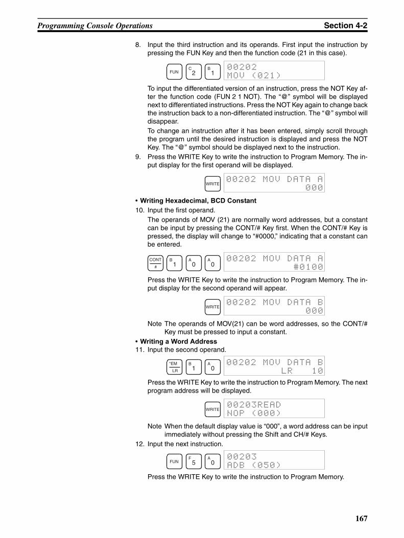
Programming Console Operations Section 4-2
8. Input the third instruction and its operands. First input the instruction bypressing the FUN Key and then the function code (21 in this case).
To input the differentiated version of an instruction, press the NOT Key af-ter the function code (FUN 2 1 NOT). The “@” symbol will be displayednext to differentiated instructions. Press the NOT Key again to change backthe instruction back to a non-differentiated instruction. The “@” symbol willdisappear.To change an instruction after it has been entered, simply scroll throughthe program until the desired instruction is displayed and press the NOTKey. The “@” symbol should be displayed next to the instruction.
9. Press the WRITE Key to write the instruction to Program Memory. The in-put display for the first operand will be displayed.
• Writing Hexadecimal, BCD Constant10. Input the first operand.
The operands of MOV (21) are normally word addresses, but a constantcan be input by pressing the CONT/# Key first. When the CONT/# Key ispressed, the display will change to “#0000,” indicating that a constant canbe entered.
Press the WRITE Key to write the instruction to Program Memory. The in-put display for the second operand will appear.
Note The operands of MOV(21) can be word addresses, so the CONT/#Key must be pressed to input a constant.
• Writing a Word Address11. Input the second operand.
Press the WRITE Key to write the instruction to Program Memory. The nextprogram address will be displayed.
Note When the default display value is “000”, a word address can be inputimmediately without pressing the Shift and CH/# Keys.
12. Input the next instruction.
Press the WRITE Key to write the instruction to Program Memory.
FUNC2
B1
WRITE
CONT
#
B1
A0
A0
WRITE
*EM
LR
B1
A0
WRITE
FUNF5
A0
167

Programming Console Operations Section 4-2
• Writing an Unsigned Decimal Number13. The first operand is input as an unsigned integer.
Input the value of the operand from 0 to 65535.
Note If an erroneous input is made, press the CLR Key to restore the sta-tus prior to the input. Then enter the correct input.
14. Restore the hexadecimal display.
Note If an input is made outside of the permissible range, a buzzer willsound and the hexadecimal display will not be displayed.
15. The second operand is input as a signed integer.
Input the value of the operand from –32,768 to 32,767. Use the SET Keyto input a positive number, and use the RESET Key to input a negativenumber.
Note If an erroneous input is made, press the CLR Key to restore the sta-tus prior to the input. Then enter the correct input.
16. Restore the hexadecimal display.
• Writing a Word Address (DM 0000)17. Input the final operand and then press the WRITE Key. (It isn’t necessary
to input leading zeroes.)
4-2-10 Instruction SearchThis operation is used to find occurrences of the specified instruction in theprogram and is possible in any mode.
WRITE
CONT
#SHIFT TR NOT
C2
F5 6
SHIFT TR
WRITE
CONT
#SHIFT TR
RESETB1
A0
SHIFT TR
WRITE
DM
EM
WRITE
RUN MONITOR PROGRAM
OK OK OK
168

Programming Console Operations Section 4-2
The ON/OFF status of any displayed bit will be shown if the PC is in RUN orMONITOR mode.
1,2,3... 1. Press the CLR Key to bring up the initial display.2. Input the address from which the search will begin and press the Down Ar-
row Key. It is not necessary to input leading zeroes.
3. Input the instruction to be found and press the SRCH Key. In this case, thesearch is for OUT 01000.In this case, the next OUT 01000 instruction is at address 200, as shownbelow.
4. Press the Down Arrow Key to display the instruction’s operands or pressthe SRCH Key to search for the next occurrence of the instruction.
5. The search will continue until an END instruction or the end of ProgramMemory is reached. In this case, an END instruction was reached at ad-dress 397.
4-2-11 Bit Operand SearchThis operation is used to find occurrences of the specified operand bit in theprogram and is possible in any mode.
The ON/OFF status of any displayed bit will be shown if the PC is in RUN orMONITOR mode.
1,2,3... 1. Press the CLR Key to bring up the initial display.2. Input the operand address. It is not necessary to input leading zeroes.
3. Press the SRCH Key to begin the search.
4. Press the SRCH Key to search for the next occurrence of the operand bit.
5. The search will continue until an END instruction or the end of ProgramMemory is reached. In this case, an END instruction was reached.
B1
A0
A0
OUTB1
A0
A0
A0 SRCH
SRCH
Indicates the address of END instruction.
Indicates the amount used by the user program in units of 0.1 Kwords.
RUN MONITOR PROGRAM
OK OK OK
SHIFTCONT
#
F5
SRCH
SRCH
169

Programming Console Operations Section 4-2
4-2-12 Inserting and Deleting InstructionsThis operation is used to insert or delete instructions from the program. It ispossible in PROGRAM mode only.
To demonstrate this operation, an IR 00105 NO condition will be inserted atprogram address 00206 and an IR 00103 NO condition deleted from address00205, as shown in the following diagram.
Insertion Follow the procedure below to insert the IR 00105 NO condition at address00206.
1,2,3... 1. Press the CLR Key to bring up the initial display.2. Input the address where the NO condition will be inserted and press the
Down Arrow Key. It is not necessary to input leading zeroes.
3. Input the new instruction and press the INS Key.
4. Press the Down Arrow Key to insert the new instruction.
Note For instructions that require more operands (such as set values), in-put the operands and then press the WRITE Key.
Deletion Follow the procedure below to delete the IR 00103 NO condition at address00205.
1,2,3... 1. Press the CLR Key to bring up the initial display.2. Input the address where the NO condition will be deleted and press the
Down Arrow Key. It is not necessary to input leading zeroes.
3. Press the DEL Key.
SRCH
Indicates the address of END instruction.
Indicates the amount used by the user program in units of 0.1 Kwords.
RUN MONITOR PROGRAM
No No OK
0010400100 00103
00105
00101
00201
END(01)
00102
01000
Delete
Insert
Original Pr ogram
Address Instruction Operands
00205 AND 0010300206 AND NOT 00104
00207 OUT 0100000208 END(01)
DeleteInsert
-
C2
A0 6
AND B1
A0
F5 INS
C2
A0
F5
170

Programming Console Operations Section 4-2
4. Press the Up Arrow Key to delete the specified instruction.If the instruction has more operands, the operands will be deleted automat-ically with the instruction.
After completing the insertion and deletion procedures, use the Up and DownArrow Keys to scroll through the program and verify that it has been changedcorrectly, as shown in the following diagram.
4-2-13 Checking the ProgramThis operation checks for programming errors and displays the programaddress and error when errors are found. It is possible in PROGRAM modeonly.
1,2,3... 1. Press the CLR Key to bring up the initial display.
2. Press the SRCH Key. An input prompt will appear requesting the desiredcheck level.
3. Input the desired check level (0, 1, or 2). The program check will beginwhen the check level is input, and the first error found will be displayed.
Note Refer to 5-4 Programming Errors for details on check levels and theerrors that may be detected when the program is checked.
4. Press the SRCH Key to continue the search. The next error will be dis-played. Continue pressing the SRCH Key to continue the search.The search will continue until an END instruction or the end of ProgramMemory is reached. A display like this will appear if the end of ProgramMemory is reached:
A display like this will appear if an END instruction is reached:
DEL
0010400100 0010500101
00201
END(01)
00102
01000
Corrected Program
Address Instruction Operands
00205 AND 0010500206 AND NOT 0010400207 OUT 0100000208 END(01) -
RUN MONITOR PROGRAM
No No OK
SRCH
A0
SRCH
171

Programming Console Operations Section 4-2
If errors are displayed, edit the program to correct the errors and check theprogram again. Continue checking the program by pressing the SRCH Keyagain until all errors have been corrected.
4-2-14 Bit, Digit, Word MonitorThis operation is used to monitor the status of up to 16 bits and words,although only 3 can be shown on the display at any one time. Operation ispossible in any mode.
Program Read then Monitor
When a program address is being displayed, the status of the bit or word inthat address can be monitored by pressing the MONTR Key.
1,2,3... 1. Press the CLR Key to bring up the initial display.2. Input the desired program address and press the Down Arrow Key.
3. Press the MONTR Key to begin monitoring.
If the status of a bit is being monitored, that bit’s status can be changedusing the Force Set/Reset operation. Refer to 4-2-26 Force Set, Reset fordetails.If the status of a word is being monitored, that word’s value can be changedusing the Hexadecimal/BCD Data Modification operation. Refer to 4-2-22Hexadecimal, BCD Data Modification, 4-2-23 Binary Data Modification, 4-2-24 Signed Decimal Data Modification, and 4-2-25 Unsigned DecimalData Modification for details.
4. Press the CLR Key to end monitoring.
Bit Monitor Follow the procedure below to monitor the status of a particular bit.
1,2,3... 1. Press the CLR Key to bring up the initial display.2. Input the bit address of the desired bit and press the MONTR Key.
The Up or Down Arrow Key can be pressed to display the status of the pre-vious or next bit.The displayed bit’s status can be changed using the Force Set/Reset op-eration in MONITOR or PROGRAM mode. Refer to 4-2-26 Force Set, Re-set for details.
3. Press the CLR Key to end monitoring.
SRCH
No more errors exist if the END instruction is displayed.
RUN MONITOR PROGRAM
OK OK OK
C2
A0
A0
MONTR
CLR00200
TIM 000
SHIFT CONT
#
B1 MONTR
CLR
172

Programming Console Operations Section 4-2
Word Monitor Follow the procedure below to monitor the status of a particular word.
1,2,3... 1. Press the CLR Key to bring up the initial display.2. Input the word address of the desired word.
3. Press the MONTR Key to begin monitoring.
The Up or Down Arrow Key can be pressed to display the status of the pre-vious or next word.The displayed word’s status can be changed using the Hexadecimal/BCDData Modification operation. Refer to 4-2-22 Hexadecimal, BCD DataModification, 4-2-23 Binary Data Modification, 4-2-24 Signed DecimalData Modification, and 4-2-25 Unsigned Decimal Data Modification for de-tails.
4. Press the CLR Key to end monitoring.
Note The operating mode can be changed without altering the current monitor dis-play by holding down the SHIFT Key and then changing the operating mode.
Multiple Address Monitoring
The status of up to six bits and words can be monitored simultaneously,although only three can be shown on the display at any one time.
1,2,3... 1. Press the CLR Key to bring up the initial display.2. Input the address of the first bit or word and press the MONTR Key.
3. Repeat step 2 up to 6 times to display the next addresses to be monitored.
If 4 or more bits and words are being monitored, the bits and words that donot appear on the display can be displayed by pressing the MONTR Key.If the MONTR Key is pressed alone, the display will shift to the right.If more than six bits and words are input, monitoring of the bit or word inputfirst will be canceled.
4. Press the CLR Key to stop monitoring the leftmost bit or word and clear itfrom the display.
5. Press the SHIFT and CLR Keys to end monitoring altogether.
Note Press the SHIFT Key, CLR Key, and then CLR Key again to return to the initialProgramming Console display with the multiple address monitoring state
SHIFTCH
*DM LR
*EM B1
MONTR
CLR
TIM MONTR
SHIFT CONT
#
B1 MONTR
DM
EMMONTR
CLR
SHIFT CLR
173

Programming Console Operations Section 4-2
unchanged. Press the SHIFT Key and then the MONTR Key from the initialdisplay to return to the multiple address monitoring state. The monitoringstates can be retained for 6 bits and words.The operating mode can be changed without altering the current monitor dis-play by holding down the SHIFT Key and then changing the operating mode.
4-2-15 Differentiation MonitorThis operation is used to monitor the up or down differentiation status of a par-ticular bit. When detected, the up or down differentiation will be displayed andthe buzzer will sound. It is possible in any mode.
1,2,3... 1. Monitor the status of the desired bit according to the procedure describedin 4-2-14 Bit, Digit, Word Monitor. If 2 or more bits are being monitored, thedesired bit should be leftmost on the display.
In this case the differentiation status of LR 00 will be monitored.
2. To specify up-differentiation monitoring, press the SHIFT and then the UpArrow Key. The symbols “U@” will appear.
To specify down-differentiation monitoring, press the SHIFT and then theDown Arrow Key. The symbols “D@” will appear.
3. The buzzer will sound when the specified bit goes from off to on (for up-differentiation) or from on to off (for down-differentiation).
Note The buzzer will not sound if it has been turned off.4. Press the CLR Key to end differentiation monitoring and return to the nor-
mal monitoring display.
4-2-16 Binary MonitorThis operation is used to monitor the ON/OFF status of any word’s 16 bits. It ispossible in any mode.
1,2,3... 1. Monitor the status of the desired word according to the procedure de-scribed in 4-2-14 Bit, Digit, Word Monitor. The desired word should be left-most on the display if 2 or more words are being monitored.
(Word monitor)
RUN MONITOR PROGRAM
OK OK OK
SHIFT
Indicates waiting for the bit to turn ON.
SHIFT
CLR
RUN MONITOR PROGRAM
OK OK OK
174

Programming Console Operations Section 4-2
2. Press the SHIFT and then the MONTR Key to begin binary monitoring. TheON/OFF status of the selected word’s 16 bits will be shown along the bot-tom of the display. A 1 indicates a bit is on, and a 0 indicates it is off.
The status of force-set bits is indicated by “S,” and the status of a force-re-set bits is indicated by “R,” as shown below.
Note a) The status of displayed bits can be changed at this point. Refer to4-2-23 Binary Data Modification for details.
b) The Up or Down Arrow Key can be pressed to display the statusof the previous or next word’s bits.
3. Press the CLR Key to end binary monitoring and return to the normal mon-itoring display.
4-2-17 Three-Word MonitorThis operation is used to monitor the status of three consecutive words. It ispossible in any mode.
1,2,3... 1. Monitor the status of the first of the three words according to the proceduredescribed in 4-2-14 Bit, Digit, Word Monitor.If 2 or more words are being monitored, the desired first word should beleftmost on the display.
(Word monitor)2. Press the EXT Key to begin 3-word monitoring. The status of the selected
word and the next two words will be displayed, as shown below. In thiscase, DM 0000 was selected.
The Up and Down Arrow Keys can be used to shift one address up ordown.The status of the displayed words can be changed at this point. Refer to 4-2-20 Three-Word Data Modification.The display can be changed to display ASCII text, which is useful whenthree consecutive words containing an ASCII message are displayed. Re-fer to 4-2-28 Hex-ASCII Display Change.
3. Press the CLR Key to end 3-word monitoring and return to the normalmonitoring display. The rightmost word on the 3-word monitor display willbe monitored.
SHIFT MONTR
Bit 15 Bit 00
Force-set bit
Force-reset bit
CLR
RUN MONITOR PROGRAM
OK OK OK
EXT
175

Programming Console Operations Section 4-2
Note The operating mode can be changed without altering the current monitor dis-play by holding down the SHIFT Key and then changing the operating mode.
4-2-18 Signed Decimal MonitorThis operation converts the contents of the specified word from signed hexa-decimal (two’s complement format) to signed decimal for display. The opera-tion can be executed while using I/O monitoring, multiple address monitoringor 3-word monitoring.
1,2,3... 1. Monitor the word that is to be used for decimal monitor with sign. Duringmultiple address monitoring, the leftmost word will be converted.
(Multiple address monitor)2. Press the SHIFT+TR Keys to display the leftmost word as signed decimal.
At this point, the contents of the displayed word can be changed with asigned-decimal input. Refer to 4-2-24 Signed Decimal Data Modification.
3. Press the CLR Key or the SHIFT+TR Keys to end the unsigned decimaldisplay and return to normal monitoring.
4-2-19 Unsigned Decimal MonitorThis operation is used to convert hexadecimal data in a word to unsigned dec-imal for display. The operation can be executed while using I/O monitoring,multiple address monitoring or 3-word monitoring.
1,2,3... 1. Monitor the word that is to be used for decimal monitor without sign. Duringmultiple address monitoring, the leftmost word will be converted.
Multiple address monitoring2. Press the SHIFT+TR+NOT Keys to display the leftmost word as unsigned
decimal.
At this point, the contents of the displayed word can be changed with anunsigned-decimal input. Refer to 4-2-25 Unsigned Decimal Data Modifica-tion.
3. Press the CLR Key or the SHIFT+TR Keys to end the unsigned decimaldisplay and return to normal monitoring.
CLR
RUN MONITOR PROGRAM
OK OK OK
SHIFT TR
CLR
RUN MONITOR PROGRAM
OK OK OK
SHIFT TR NOT
176

Programming Console Operations Section 4-2
4-2-20 Three-Word Data ModificationThis operation is used to change the contents of one or more of the 3 consec-utive words displayed in the Three-Word Monitor operation. It is possible inMONITOR or PROGRAM mode only.
!Caution Before changing the contents of I/O memory, be sure that the changes will notcause equipment to operate unexpectedly or dangerously. In particular, takecare when changing the status of output bits. The PC continues to refresh I/Obits even if the PC is in PROGRAM mode, so devices connected to outputpoints on the CPU Unit, Expansion Units, or Expansion I/O Units may operateunexpectedly.
1,2,3... 1. Monitor the status of the desired words according to the procedure de-scribed 4-2-17 Three-Word Monitor.
(Three-word monitor)2. Press the CHG Key to begin 3-word data modification. The cursor will ap-
pear next to the contents of the leftmost word.
3. Input the new value for the leftmost word on the display and press the CHGKey if more changes will be made.(Input the new value and press the WRITE Key to write the changes inmemory if no more changes will be made.)
4. Input the new value for the middle word on the display and press the CHGKey if the rightmost word will be changed. Input the new value and pressthe WRITE Key to write the changes in memory if the rightmost word willnot be changed. (In this case, it will not.)
Note If the CLR Key is pressed before the WRITE Key, the operation will be can-celled and the 3-word monitor display will return without any changes in datamemory.
4-2-21 Changing Timer, Counter SVThere are two operations that can be used to change the SV of a timer orcounter. They are possible in MONITOR or PROGRAM mode only. In MONI-TOR mode, the SV can be changed while the program is being executed.
The timer or counter SV can be changed either by inputting a new value or byincrementing or decrementing the current SV.
Inputting a New SV Constant
This operation can be used to input a new SV constant, as well as to changean SV from a constant to a word address designation and vice versa. The fol-
CLR
RUN MONITOR PROGRAM
No OK OK
CHG
B1 CHG
C2
D3
E4 WRITE
RUN MONITOR PROGRAM
No OK OK
177

Programming Console Operations Section 4-2
lowing examples show how to input a new SV constant and how to change theSV from a constant to an address.
1,2,3... 1. Press the CLR Key to bring up the initial display.
2. Display the desired timer or counter.
3. Press the Down Arrow Key and then the CHG Key.
4. At this point a new SV constant can be input or the SV constant can bechanged to a word address designationa) To input a new SV constant, input the constant and press the WRITE
Key.
b) To change to a word address designation, input the word address andpress the WRITE Key.
Incrementing and Decrementing a Constant
This operation can be used to increment and decrement an SV constant. It ispossible only when the SV has been entered as a constant.
1,2,3... 1. Press the CLR Key to bring up the initial display.2. Display the desired timer or counter.
3. Press the Down Arrow, CHG, and then the EXT Key.
The constant on the left is the old SV and the constant on the right will be-come the new SV constant in step 5.
4. Press the Up and Down Arrow Keys to increment and decrement the con-stant on the right. (In this case the SV is incremented once.)
5. Press the CLR Key twice to change the timer’s SV to the new value.
4-2-22 Hexadecimal, BCD Data ModificationThis operation is used to change the BCD or hexadecimal value of a wordbeing monitored using the procedure described in 4-2-14 Bit, Digit, WordMonitor. It is possible in MONITOR or PROGRAM mode only.
Words SR 253 to SR 255 cannot be changed.
TIMB1 SRCH
CHG
B1
C2
E4 WRITE
SHIFTCH
*DM
AR
HR
B1
A0 WRITE
TIM SRCH
CHG EXT
CLR CLR
RUN MONITOR PROGRAM
No OK OK
178

Programming Console Operations Section 4-2
!Caution Before changing the contents of I/O memory, be sure that the changes will notcause equipment to operate unexpectedly or dangerously. In particular, takecare when changing the status of output bits. The PC continues to refresh I/Obits even if the PC is in PROGRAM mode, so devices connected to outputpoints on the CPU Unit, Expansion Units, or Expansion I/O Units may operateunexpectedly.
1,2,3... 1. Monitor the status of the desired word according to the procedure de-scribed in 4-2-14 Bit, Digit, Word Monitor. If two or more words are beingmonitored, the desired word should be leftmost on the display.
(Word monitor)2. Press the CHG Key to begin hexadecimal, BCD data modification.
3. Input the new PV and press the WRITE Key to change the PV.The operation will end and the normal monitoring display will return whenthe WRITE Key is pressed.
4-2-23 Binary Data ModificationThis operation is used to change the status of a word’s bits when the word ismonitored using the procedure described in 4-2-16 Binary Monitor. It is possi-ble in MONITOR or PROGRAM mode only.
Bits SR 25300 to SR 25507 and timer/counter flags cannot be changed.
!Caution Before changing the contents of I/O memory, be sure that the changes will notcause equipment to operate unexpectedly or dangerously. In particular, takecare when changing the status of output bits. The PC continues to refresh I/Obits even if the PC is in PROGRAM mode, so devices connected to outputpoints on the CPU Unit, Expansion Units, or Expansion I/O Units may operateunexpectedly.
1,2,3... 1. Monitor the status of the desired word according to the procedure de-scribed 4-2-16 Binary Monitor.
(BInary monitor)
2. Press the CHG Key to begin binary data modification.
A flashing cursor will appear over bit 15. The cursor indicates which bit canbe changed.
3. Three sets of keys are used to move the cursor and change bit status:a) Use the Up and Down Arrow Keys to move the cursor to the left and
right.
CHG
C2
A0
A0 WRITE
D0000
0200
RUN MONITOR PROGRAM
No OK OK
Bit 15 Bit 00
CHG c010 CHG?~000010101010101
179
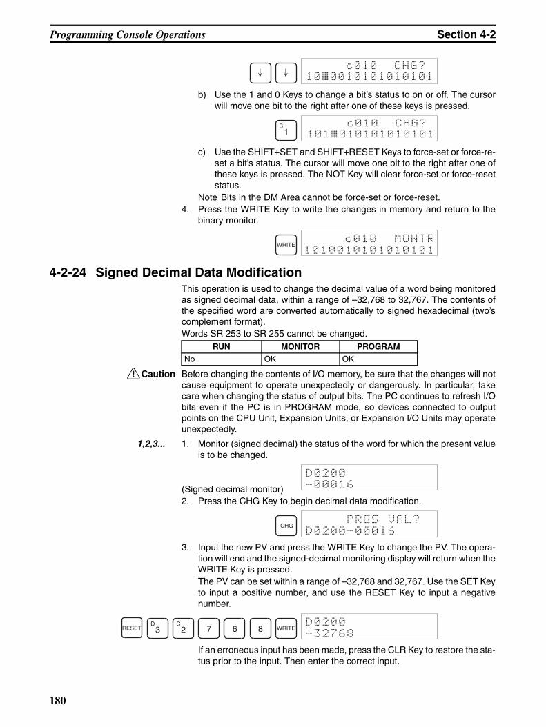
Programming Console Operations Section 4-2
b) Use the 1 and 0 Keys to change a bit’s status to on or off. The cursorwill move one bit to the right after one of these keys is pressed.
c) Use the SHIFT+SET and SHIFT+RESET Keys to force-set or force-re-set a bit’s status. The cursor will move one bit to the right after one ofthese keys is pressed. The NOT Key will clear force-set or force-resetstatus.
Note Bits in the DM Area cannot be force-set or force-reset.4. Press the WRITE Key to write the changes in memory and return to the
binary monitor.
4-2-24 Signed Decimal Data ModificationThis operation is used to change the decimal value of a word being monitoredas signed decimal data, within a range of –32,768 to 32,767. The contents ofthe specified word are converted automatically to signed hexadecimal (two’scomplement format).Words SR 253 to SR 255 cannot be changed.
!Caution Before changing the contents of I/O memory, be sure that the changes will notcause equipment to operate unexpectedly or dangerously. In particular, takecare when changing the status of output bits. The PC continues to refresh I/Obits even if the PC is in PROGRAM mode, so devices connected to outputpoints on the CPU Unit, Expansion Units, or Expansion I/O Units may operateunexpectedly.
1,2,3... 1. Monitor (signed decimal) the status of the word for which the present valueis to be changed.
(Signed decimal monitor)2. Press the CHG Key to begin decimal data modification.
3. Input the new PV and press the WRITE Key to change the PV. The opera-tion will end and the signed-decimal monitoring display will return when theWRITE Key is pressed.The PV can be set within a range of –32,768 and 32,767. Use the SET Keyto input a positive number, and use the RESET Key to input a negativenumber.
If an erroneous input has been made, press the CLR Key to restore the sta-tus prior to the input. Then enter the correct input.
c010 CHG?10~0010101010101
B1
c010 CHG?101~010101010101
WRITE
RUN MONITOR PROGRAM
No OK OK
CHG
RESETD3
C2 7 6 8 WRITE
180

Programming Console Operations Section 4-2
The buzzer will sound if a value outside the specified range is input, allow-ing no writing.
4-2-25 Unsigned Decimal Data ModificationThis operation is used to change the decimal value of a word being monitoredas unsigned decimal data, within a range of 0 to 65,535. A change into hexa-decimal data is made automatically.
Words SR 253 to SR 255 cannot be changed.
!Caution Before changing the contents of I/O memory, be sure that the changes will notcause equipment to operate unexpectedly or dangerously. In particular, takecare when changing the status of output bits. The PC continues to refresh I/Obits even if the PC is in PROGRAM mode, so devices connected to outputpoints on the CPU Unit, Expansion Units, or Expansion I/O Units may operateunexpectedly.
1,2,3... 1. Monitor (unsigned decimal) the status of the word for which the presentvalue is to be changed.
(Unsigned decimal monitor)2. Press the CHG Key to begin decimal data modification.
3. Input the new PV and press the WRITE Key to change the PV. The opera-tion will end and the decimal-without-sign monitoring display will returnwhen the WRITE Key is pressed.The PV can be set within a range of 0 to 65,535.
If an erroneous input has been made, press the CLR Key to restore the sta-tus prior to the input. Then enter the correct input.The buzzer will sound if a value outside the specified range is input, allow-ing no writing.
4-2-26 Force Set, ResetThis operation is used to force bits ON (force set) or OFF (force reset) and isuseful when debugging the program or checking output wiring. It is possible inMONITOR or PROGRAM mode only.
!Caution Before changing the contents of I/O memory, be sure that the changes will notcause equipment to operate unexpectedly or dangerously. In particular, takecare when changing the status of output bits. The PC continues to refresh I/Obits even if the PC is in PROGRAM mode, so devices connected to outputpoints on the CPU Unit, Expansion Units, or Expansion I/O Units may operateunexpectedly.
RUN MONITOR PROGRAM
No OK OK
CHG
D3
C2 7 6 8 WRITE
RUN MONITOR PROGRAM
No OK OK
181

Programming Console Operations Section 4-2
1,2,3... 1. Monitor the status of the desired bit according to the procedure describedin 4-2-14 Bit, Digit, Word Monitor. If two or more words are being moni-tored, the desired bit should be leftmost on the display.
(Multiple address monitor)2. Press the SET Key to force the bit ON or press the RESET Key to force the
bit OFF.
The cursor in the lower left corner of the display indicates that the force set/reset is in progress. Bit status will remain ON or OFF only as long as thekey is held down; the original status will return one cycle after the key isreleased.
3. Press the SHIFT and SET Keys or SHIFT and RESET Keys to maintain thestatus of the bit after the key is released. In this case, the force-set statusis indicated by an “S” and the force-reset status is indicated by an “R.”To return the bit to its original status, press the NOT Key or perform theClear Force Set/Reset operation. Refer to 4-2-27 Clear Force Set/Resetfor details.Forced status will also be cleared in the following cases:a) When the PC’s operating mode is changed (although the forced status
will not be cleared when the mode is changed from PROGRAM toMONITOR if SR 25211 is ON)
b) When the PC stops because a fatal error occurredc) When the PC stops because of a power interruptiond) When the Clear Force Set/Reset Operation is performed
4-2-27 Clear Force Set/ResetThis operation is used to restore the status of all bits which have been forceset or reset. It is possible in MONITOR or PROGRAM mode only.
!Caution Before changing the contents of I/O memory, be sure that the changes will notcause equipment to operate unexpectedly or dangerously. In particular, takecare when changing the status of output bits. The PC continues to refresh I/Obits even if the PC is in PROGRAM mode, so devices connected to outputpoints on the CPU Unit, Expansion Units, or Expansion I/O Units may operateunexpectedly.
1,2,3... 1. Press the CLR Key to bring up the initial display.2. Press the SET and then the RESET Key. A confirmation message will ap-
pear.
Note If you mistakenly press the wrong key, press CLR and start againfrom the beginning.
3. Press the NOT Key to clear the force-set/reset status of bits in all data ar-eas.
SET
RUN MONITOR PROGRAM
No OK OK
SET RESET
182

Programming Console Operations Section 4-2
4-2-28 Hex-ASCII Display ChangeThis operation is used to convert word data displays back and forth between4-digit hexadecimal data and ASCII. It is possible in any mode.The displayed PV of the timer or counter cannot be changed.
1,2,3... 1. Monitor the status of the desired word(s) according to the procedure de-scribed in 4-2-14 Bit, Digit, Word Monitor. While the multiple addresses arebeing monitored, the leftmost word is subject to change.
(Multiple address monitor)2. Press the TR Key to switch to ASCII display. The display will toggle be-
tween hexadecimal and ASCII displays each time the TR Key is pressed.
Note 1. A message contained in three words can be displayed by using ASCII dis-play in combination with the Three-word monitor operation.
2. The Hexadecimal, BCD Data Modification Operation can be used whiledisplaying ASCII data. Input values in 4-digit hexadecimal.
4-2-29 Displaying the Cycle TimeThis operation is used to display the current average cycle time (scan time). Itis possible only in RUN or MONITOR mode while the program is being exe-cuted.
1,2,3... 1. Press the CLR Key to bring up the initial display.
2. Press the MONTR Key to display the cycle time.
There might be differences in displayed values when the MONTR Key ispressed repeatedly. These differences are caused by changing executionconditions.
NOT
RUN MONITOR PROGRAM
OK OK OK
TR
TR
RUN MONITOR PROGRAM
OK OK No
MONTR
"MS" in the display indicates the unit "ms" for the cycle time.
183
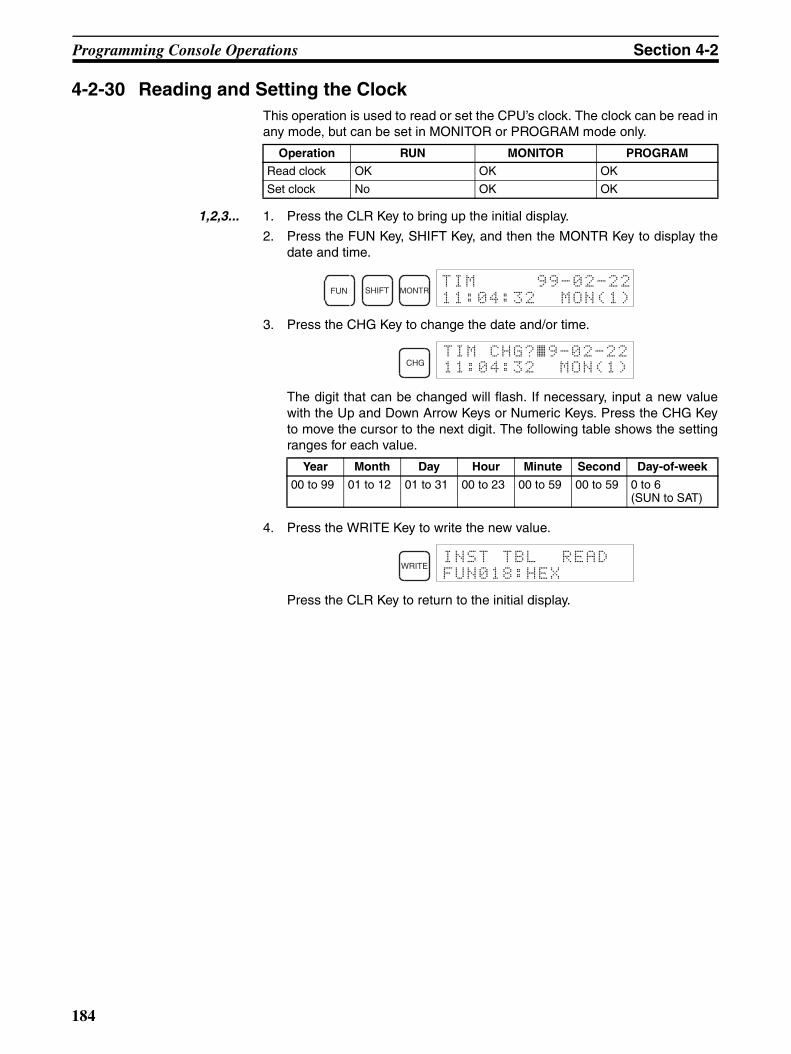
Programming Console Operations Section 4-2
4-2-30 Reading and Setting the ClockThis operation is used to read or set the CPU’s clock. The clock can be read inany mode, but can be set in MONITOR or PROGRAM mode only.
1,2,3... 1. Press the CLR Key to bring up the initial display.
2. Press the FUN Key, SHIFT Key, and then the MONTR Key to display thedate and time.
3. Press the CHG Key to change the date and/or time.
The digit that can be changed will flash. If necessary, input a new valuewith the Up and Down Arrow Keys or Numeric Keys. Press the CHG Keyto move the cursor to the next digit. The following table shows the settingranges for each value.
4. Press the WRITE Key to write the new value.
Press the CLR Key to return to the initial display.
Operation RUN MONITOR PROGRAM
Read clock OK OK OK
Set clock No OK OK
Year Month Day Hour Minute Second Day-of-week
00 to 99 01 to 12 01 to 31 00 to 23 00 to 59 00 to 59 0 to 6(SUN to SAT)
FUN SHIFT MONTR
CHGTIM CHG?~9-02-2211:04:32 MON(1)
WRITE
184

Programming Example Section 4-3
4-3 Programming ExampleThis section demonstrates all of the steps needed to write a program with theProgramming Console.
4-3-1 Preparatory OperationsUse the following procedure when writing a program to the CPM2C for the firsttime.
1,2,3... 1. Set the Programming Console’s mode switch to PROGRAM mode andturn on the CPM2C’s power supply. The password input display will appearon the Programming Console.
2. Enter the password by pressing the CLR and then the MONTR Key.
3. Clear the CPM2C’s memory by pressing the CLR, SET, NOT, RESET, andthen the MONTR Key. Press the CLR Key several times if memory errorsare displayed.
4. Display and clear error messages by pressing the CLR, FUN, and then theMONTR Key. Continue pressing the MONTR Key until all error messageshave been cleared.
5. Press the CLR Key to bring up the initial programming display (program ad-dress 00000). The new program can be written at this point.
!Caution Check the system thoroughly before starting or stopping the CPM2C to pre-vent any accidents that might occur when the program is first started.
RUNMONITOR
PROGRAM
CLR MONTR
CLR
SET NOT RESET
MONTR
CLR
FUN
MONTR
CLR
185
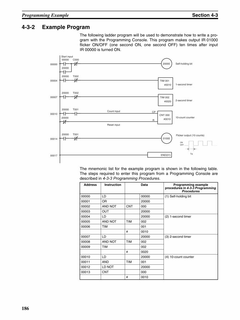
Programming Example Section 4-3
4-3-2 Example ProgramThe following ladder program will be used to demonstrate how to write a pro-gram with the Programming Console. This program makes output IR 01000flicker ON/OFF (one second ON, one second OFF) ten times after inputIR 00000 is turned ON.
The mnemonic list for the example program is shown in the following table.The steps required to enter this program from a Programming Console aredescribed in 4-3-3 Programming Procedures.
Count input
Reset input
20000
END(01)
C00000000
20000
01000
T00120000
00000
00004
00007
00010
00014
000171S
ON OFF
Flicker output (10 counts)
Self-holding bit
1-second timer
2-second timer
10-count counter
TIM 001
#0010
CP
R
CNT 000
#0010
T00220000
TIM 002
#0020
T00220000
T00120000
20000
Start input
Address Instruction Data Programming example procedures in 4-3-3 Programming
Procedures00000 LD 00000 (1) Self-holding bit
00001 OR 20000
00002 AND NOT CNT 000
00003 OUT 20000
00004 LD 20000 (2) 1-second timer
00005 AND NOT TIM 002
00006 TIM 001
# 0010
00007 LD 20000 (3) 2-second timer
00008 AND NOT TIM 002
00009 TIM 002
# 0020
00010 LD 20000 (4) 10-count counter
00011 AND TIM 001
00012 LD NOT 20000
00013 CNT 000
# 0010
186

Programming Example Section 4-3
4-3-3 Programming ProceduresThe example program will be written to the CPM2C according to the mne-monic list in 4-3-2 Example Program. The procedure is performed beginningwith the initial display. (Clear the memory before entering a new program.)
Note If an error occurs while inputting the program, refer to 5-3 Programming Con-sole Operation Errors for details on correcting the error. Refer to the relevantSupport Software Operation Manual for details on errors that appear whenoperating the SSS or SYSMAC-CPT Support Software.
(1) Inputting the Self-holding Bit1,2,3... 1. Input the normally open condition IR 00000.
(It isn’t necessary to input leading zeroes.)
2. Input the OR condition IR 20000.
3. Input the normally closed AND condition C000.(It isn’t necessary to input leading zeroes.)
4. Input the OUT instruction IR 20000.
(2) Inputting the One-second Timer1,2,3... 1. Input the normally open condition IR 20000.
00014 LD 20000 (5) Flicker output (10 counts)
00015 AND NOT TIM 001
00016 OUT 01000
00017 END (01) --- (6) END(01) instruction
Address Instruction Data Programming example procedures in 4-3-3 Programming
Procedures
LD
WRITE
OR C2
A0
A0
A0
A0
WRITE
ANDNOT CNT
WRITE
OUTC2
A0
A0
A0
A0
WRITE
LD C2
A0
A0
A0
A0
WRITE
187

Programming Example Section 4-3
2. Input the normally closed AND condition T002.(It isn’t necessary to input leading zeroes.)
3. Input the 1-second timer T001.
4. Input the SV for T001 (#0010 = 1.0 s).
(3) Inputting the Two-second Timer
The following key operations are used to input the 2-second timer.
1,2,3... 1. Input the normally open condition IR 20000.
2. Input the normally closed AND condition T002.(It isn’t necessary to input leading zeroes.)
3. Input the 2-second timer T002.
4. Input the SV for T002 (#0020 = 2.0 s).
(4) Inputting the 10-count Counter
The following key operations are used to input the 10-count counter.
1,2,3... 1. Input the normally open condition IR 20000.
ANDNOT TIM
C2
WRITE
TIMB1
WRITE
B1
A0
WRITE
LD C2
A0
A0
A0
A0
WRITE
ANDNOT TIM
C2
WRITE
TIMC2
WRITE
C2
A0
WRITE
188
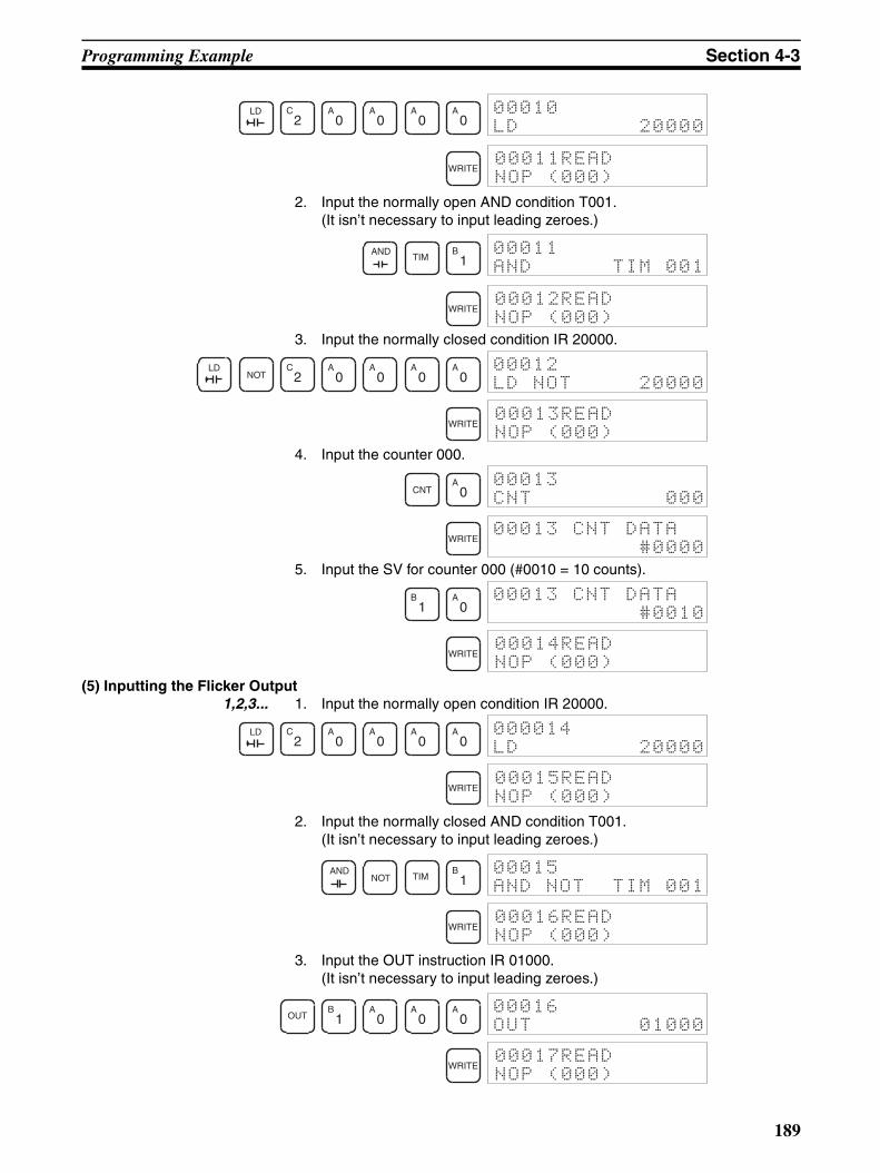
Programming Example Section 4-3
2. Input the normally open AND condition T001.(It isn’t necessary to input leading zeroes.)
3. Input the normally closed condition IR 20000.
4. Input the counter 000.
5. Input the SV for counter 000 (#0010 = 10 counts).
(5) Inputting the Flicker Output1,2,3... 1. Input the normally open condition IR 20000.
2. Input the normally closed AND condition T001.(It isn’t necessary to input leading zeroes.)
3. Input the OUT instruction IR 01000.(It isn’t necessary to input leading zeroes.)
LD C2
A0
A0
A0
A0
WRITE
ANDTIM
B1
WRITE
LDNOT
C2
A0
A0
A0
A0
WRITE
CNTA0
WRITE
B1
A0
WRITE
LD C2
A0
A0
A0
A0
WRITE
ANDNOT TIM
B1
WRITE
OUTB1
A0
A0
A0
WRITE
189

Programming Example Section 4-3
(6) Inputting the END(001) Instruction
Input END(01). (The display shows three digits in the function code, but onlythe last two digits are input for CPM2C PCs.)
4-3-4 Checking the ProgramCheck the program syntax in PROGRAM mode to make sure that the programhas been input correctly.
1,2,3... 1. Press the CLR Key to bring up the initial display.
2. Press the SRCH Key. An input prompt will appear requesting the desiredcheck level.
3. Input the desired check level (0, 1, or 2). The program check will beginwhen the check level is input, and the first error found will be displayed. Ifno errors are found, the following display will appear.
Note Refer to 5-4 Programming Errors for details on check levels and theprogramming errors that may be displayed during a program check.
4. Press the SRCH Key to continue the search. The next error will be dis-played. Continue pressing the SRCH Key to continue the search.The search will continue until an END(01) instruction or the end of ProgramMemory is reached.
If errors are displayed, edit the program to correct the errors and check theprogram again. Continue checking the program until all errors have been cor-rected.
4-3-5 Test Run in MONITOR ModeSwitch the CPM2C in MONITOR mode and check the operation of the pro-gram.
1,2,3... 1. Set the Programming Console’s mode switch to MONITOR mode.
2. Press the CLR Key to bring up the initial display.
3. Force-set the start input bit (IR 00000) from the Programming Console tostart the program.
FUN
A0
B1
WRITE
CLR
SRCH
A0
RUNMONITOR
PROGRAM
CLR
LD
190
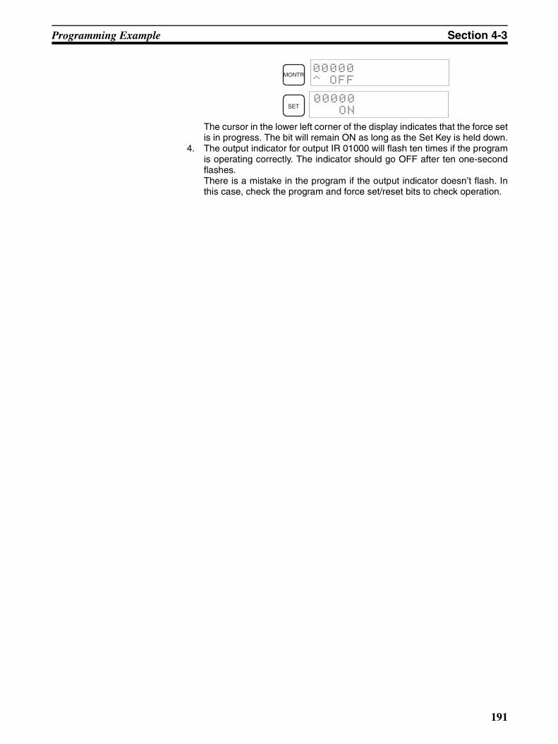
Programming Example Section 4-3
The cursor in the lower left corner of the display indicates that the force setis in progress. The bit will remain ON as long as the Set Key is held down.
4. The output indicator for output IR 01000 will flash ten times if the programis operating correctly. The indicator should go OFF after ten one-secondflashes.There is a mistake in the program if the output indicator doesn’t flash. Inthis case, check the program and force set/reset bits to check operation.
MONTR
SET
191

SECTION 5Test Runs and Error Processing
This section describes procedures for test runs of CPM2C operation, self-diagnosis functions, and error processing toidentify and correct the hardware and software errors that can occur during PC operation.
5-1 Initial System Checks and Test Run Procedure . . . . . . . . . . . . . . . . . . . . . . . 194
5-1-1 Initial System Checks. . . . . . . . . . . . . . . . . . . . . . . . . . . . . . . . . . . . 194
5-1-2 Flash Memory Precautions. . . . . . . . . . . . . . . . . . . . . . . . . . . . . . . . 194
5-1-3 CPM2C Test Run Procedure . . . . . . . . . . . . . . . . . . . . . . . . . . . . . . 194
5-2 Self-diagnostic Functions . . . . . . . . . . . . . . . . . . . . . . . . . . . . . . . . . . . . . . . . 195
5-2-1 Identifying Errors. . . . . . . . . . . . . . . . . . . . . . . . . . . . . . . . . . . . . . . 195
5-2-2 User-defined Errors . . . . . . . . . . . . . . . . . . . . . . . . . . . . . . . . . . . . . 196
5-2-3 Non-fatal Errors . . . . . . . . . . . . . . . . . . . . . . . . . . . . . . . . . . . . . . . . 196
5-2-4 Fatal Errors. . . . . . . . . . . . . . . . . . . . . . . . . . . . . . . . . . . . . . . . . . . . 197
5-2-5 Communications Errors . . . . . . . . . . . . . . . . . . . . . . . . . . . . . . . . . . 198
5-3 Programming Console Operation Errors . . . . . . . . . . . . . . . . . . . . . . . . . . . . 198
5-4 Programming Errors . . . . . . . . . . . . . . . . . . . . . . . . . . . . . . . . . . . . . . . . . . . . 198
5-5 Troubleshooting Flowcharts . . . . . . . . . . . . . . . . . . . . . . . . . . . . . . . . . . . . . . 200
5-6 Maintenance Inspections . . . . . . . . . . . . . . . . . . . . . . . . . . . . . . . . . . . . . . . . 208
5-7 Battery Replacement . . . . . . . . . . . . . . . . . . . . . . . . . . . . . . . . . . . . . . . . . . . 209
193

Initial System Checks and Test Run Procedure Section 5-1
5-1 Initial System Checks and Test Run Procedure5-1-1 Initial System Checks
Check the following items after setting up and wiring the CPM2C, but beforeperforming a test run.
Note 1. Always clear memory before beginning to program the CPM2C. Althoughmemory is cleared before the CPU Unit is shipped, the contents of the DM,HR, AR, and counter areas may change in transit. See 4-2-2 ClearingMemory for details on the All Clear operation.
2. See 1-3-3 Operating Mode at Startup to determine what mode the CPM2Cwill enter when the power is turned ON.
5-1-2 Flash Memory PrecautionsObserve the following precautions to protect the flash memory and ensureproper operation.
1,2,3... 1. If changes are made in the read-only DM area (DM 6144 through DM6599) or PC Setup (DM 6600 through DM 6655), the PC’s operating modemust be changed to write the new contents to flash memory. If backup bat-tery is changed before the changes are written to flash memory, the chang-es will be lost.The changes can be saved by switching the CPM2C to RUN or MONITORmode or turning the CPM2C OFF and then ON again.
2. When contents of the program, read-only DM (DM 6144 through DM6599), or PC Setup (DM 6600 through DM 6655) have been changed, star-tup processing will take up to 1,200 ms longer than usual. Be sure to takethis one-time startup delay into account if it may affect operations.
3. If one of the following three operations is performed in MONITOR or RUNmode, the CPM2C’s cycle time will be extended by up to 1,200 ms and in-terrupts will be disabled while the program or PC Setup is being overwrit-ten.
• Program changes with the online edit operation
• Changes to the read-only DM area (DM 6144 through DM 6599)
• Changes to the PC Setup (DM 6600 through DM 6655)
A “SCAN TIME OVER” error won’t occur during these operations. Be sureto take this delay in the CPM2C’s I/O response times into account whenperforming online editing.
5-1-3 CPM2C Test Run Procedure1,2,3... 1. Power Supply Application
a) Check the CPM2C’s power supply voltage and terminal connections.
b) Check the I/O devices’ power supply voltage and terminal connec-tions.
c) Turn ON the power supply and check that the “PWR” indicator lights.
Item Points to check
Power supply and I/O connections
Is the wiring correct?Are the terminals securely tightened?Are there any shorts between crimp terminals or wires?
Refer to 3-4 Wiring and Connections for details.
Connecting cables Are the cables all connected correctly and locked?
Refer to 3-4 Wiring and Connections for details.
Protective label Has the protective label been removed?
194
Self-diagnostic Functions Section 5-2
d) Use a Programming Device to set the CPM2C to PROGRAM mode.
2. I/O Wiring Checksa) With the CPM2C in PROGRAM mode, check the output wiring by turn-
ing ON the output bits with the force set and force reset operations.Refer to 4-2-26 Force Set, Reset for details.
b) Check the input wiring with the CPM2C’s input indicators or a Pro-gramming Device’s monitor operations.
3. Test Runa) Use a Programming Device to set the CPM2C to RUN or MONITOR
mode and check that the “RUN” indicator lights.b) Check the sequence of operation with the force set/reset operations,
etc.4. Debugging
Correct any programming errors that are detected.5. Saving the Program
a) Use a Programming Device to write the program to a backup floppydisk.
b) Print out a hard copy of the program with a printer.Note Refer to Section 4 Using Programming Devices for details on the Support
Software and Programming Console operations.
5-2 Self-diagnostic FunctionsThe CPM2C is equipped with a variety of self-diagnostic functions to helpidentify and correct errors and reduce down time.
5-2-1 Identifying ErrorsAn error can be identified by the error message displayed on a ProgrammingDevice, error flags in the AR and SR areas, and the error code output toSR 253.
Fatal and Non-fatal Errors PC errors are divided into 2 categories based on the severity of the errors.The status of the ERR/ALM indicator (lit or flashing) shows which type of errorhas occurred.
ERR/ALM Lit (Fatal Error)
Fatal errors are serious errors which stop CPM2C operation. There are twoways to restart operation:
• Turn the PC OFF and then ON again.• Use a Programming Device to switch the PC to PROGRAM mode, and
read/clear the error.ERR/ALM Flashing (Non-fatal Error)
Non-fatal errors are less serious errors which don’t stop CPM2C operation.
Error Messages When an error is detected, a corresponding error message will be displayedon the Programming Console or other Programming Device connected to thePC.
Error Flags When a hardware error is detected, the corresponding error flag in the AR orSR area will be turned ON.
Error Code When an error is detected, a specific 2-digit hexadecimal error code is outputto SR 25300 to SR 25307. The error code and time of occurrence are alsooutput to the Error Log Area (DM 2000 to DM 2021).
!WARNING Emergency stop circuits, interlock circuits, limit circuits, and similar safetymeasures must be provided in external control circuits (i.e., not in the Pro-grammable Controller) to ensure safety in the system if an abnormality occurs
195

Self-diagnostic Functions Section 5-2
due to malfunction of the PC or another external factor affecting the PC oper-ation. Not providing proper safety measures may result in serious accidents.
!WARNING The PC will turn OFF all outputs when its self-diagnosis function detects anyerror or when a severe failure alarm (FALS) instruction is executed. Externalsafety measures must be provided to ensure safety in the system. Not provid-ing proper safety measures may result in serious accidents.
5-2-2 User-defined ErrorsThere are three instructions that can be used to define errors or messages.FAL(06) causes a non-fatal error, FAL(07) causes a fatal error, and MSG(46)sends a message to the Programming Console or host computer connectedto the PC.
FAILURE ALARM – FAL(06)
FAL(06) is an instruction that causes a non-fatal error. The following will occurwhen an FAL(06) instruction is executed:
1,2,3... 1. The ERR/ALM indicator on the CPU Unit will flash. PC operation will con-tinue.
2. The instruction’s 2-digit BCD FAL number (01 to 99) will be written toSR 25300 to SR 25307.
The FAL numbers can be set arbitrarily to indicate particular conditions, butthe same number should not be used as both an FAL number and an FALSnumber.To clear an FAL error, correct the cause of the error and then execute FAL 00or use a Programming Device to clear the error.
SEVERE FAILURE ALARM – FALS(07)
FALS(07) is an instruction that causes a fatal error. The following will occurwhen an FALS(07) instruction is executed:
1,2,3... 1. Program execution will be stopped and all outputs will be turned OFF.2. The ERR/ALM indicator on the CPU Unit will be lit.3. The instruction’s 2-digit BCD FALS number (01 to 99) will be written to
SR 25300 to SR 25307.The FALS numbers can be set arbitrarily to indicate particular conditions, butthe same number should not be used as both an FAL number and an FALSnumber.To clear an FALS error, use a Programming Device to switch the PC to PRO-GRAM Mode, correct the cause of the error, and then clear the error.
MESSAGE – MSG(46) MSG(46) is used to display a message on a Programming Device connectedto the CPM2C. The message, which can be up to 16 characters long, is dis-played when the instruction’s execution condition is ON.
5-2-3 Non-fatal ErrorsPC operation and program execution will continue after one or more of theseerrors have occurred. Although PC operation will continue, the cause of theerror should be corrected and the error cleared as soon as possible.
196

Self-diagnostic Functions Section 5-2
When one of these errors occurs, the POWER and RUN indicators will remainlit and the ERR/ALM indicator will flash.
5-2-4 Fatal ErrorsPC operation and program execution will stop and all outputs from the PC willbe turned OFF when any of these errors have occurred. CPM2C operationcan’t be restarted until the PC is turned OFF and then ON again or a Pro-gramming Device is used to switch the PC to PROGRAM mode and clear thefatal error.
All CPU Unit indicators will be OFF for the power interruption error. For allother fatal operating errors, the POWER and ERR/ALM indicators will be lit.The RUN indicator will be OFF.
Message FAL No. Meaning and appropriate response
SYS FAIL FAL**(** is 01 to 99 or 9B.)
01 to 99 An FAL(06) instruction has been executed in the program. Check the FAL number to determine conditions that would cause execution, correct the cause, and clear the error.
9B An error has been detected in the PC Setup. Check flags AR 1300 to AR 1302, and correct as directed.AR 1300 ON: An incorrect setting was detected in the PC Setup (DM 6600 to DM 6614) when power was turned ON. Correct the settings in PROGRAM Mode and turn ON the power again.AR 1301 ON: An incorrect setting was detected in the PC Setup (DM 6615 to DM 6644) when switching to RUN or MONITOR mode. Correct the settings in PRO-GRAM Mode and switch to RUN or MONITOR mode again.AR 1302 ON: An incorrect setting was detected in the PC Setup (DM 6645 to DM 6655) during operation. Correct the settings and clear the error.
SCAN TIME OVER F8 The cycle time has exceeded 100 ms. (SR 25309 will be ON.)This indicates that the program cycle time is longer than recommended. Reduce cycle time if possible. (The CPM2C can be set so that this error won’t be detected.)
Battery error
(no message)
F7 If the Low Battery Detection Switch is ON and the voltage of the CPM2C-BAT01 backup battery is below the minimum level, the ERR/ALM indicator will flash and SR 25308 will be turned ON. (See page 49 for details on the Low Battery Detection Switch.)
Replace the battery. (See 5-7 Battery Replacement for details.)
Message FALS No.
Meaning and appropriate response
Power interruption(no message)
None Power has been interrupted for more than 10 ms (2 ms for DC power types.)Check power supply voltage and power lines. Try to power-up again.
MEMORY ERR F1 AR 1308 ON: There is a non-existent bit or word address in the user program. Check the program and correct errors.
AR 1309 ON: An error has occurred in flash memory. Replace the CPU Unit.
AR 1310 ON: A checksum error has occurred in read-only DM (DM 6144 to DM 6599). Check and correct the settings in the read-only DM area.
AR 1311 ON: A checksum error has occurred in the PC Setup. Initialize the PC Setup and input the settings again.
AR 1312 ON: A checksum error has occurred in the program. Check the program and correct any errors detected.
AR 1313 ON: A checksum error has occurred in the expansion instructions data and all function codes have been set the their default values. Reset the expansion instructions.
AR 1314 ON: Data was not maintained in an area specified for holding. Clear the error, check the data in the areas specified for holding, and try again.
NO END INST F0 END(01) is not written in the program. Write END(01) at the end of the program.
I/O BUS ERR C0 An error has occurred during data transfer between the CPU Unit and an Expansion I/O Unit or Expansion Unit. Check the Unit’s connecting cable.
I/O UNIT OVER E1 Too many Expansion Units or Expansion I/O Units have been connected. Check the Unit configuration.
197

Programming Console Operation Errors Section 5-3
5-2-5 Communications ErrorsThe COMM indicator will be turned OFF and AR 0812 will be turned ON if anerror occurs in communications through the peripheral port or AR 0804 will beturned ON if an error occurs in communications through the RS-232C port.Check the connecting cables and restart.
There are no error messages or error codes generated by this error and theERR/ALM indicator is not affected.
5-3 Programming Console Operation ErrorsThe following error messages may appear when performing operations on theProgramming Console. Correct the error as indicated and continue operation.
Note Refer to the relevant Support Software Operation Manual for details on errorsthat may appear when operating the SSS or SYSMAC-CPT Support Soft-ware.
5-4 Programming ErrorsThese errors in program syntax will be detected when the program is checkedusing the Program Check operation.
Three levels of program checking are available. The desired level must bedesignated to indicate the type of errors that are to be detected. The followingtable provides the error types, displays, and explanations of all syntax errors.
SYS FAIL FALS**(** is 01 to 99 or 9F.)
01 to 99 A FALS(07) instruction has been executed in the program. Check the FALS number to determine the conditions that caused execution, correct the cause, and clear the error.
9F The cycle time has exceeded the Maximum (Watch) Cycle Time setting (DM 6618). Check the cycle time and adjust the Maximum Cycle Time setting if necessary.
Message FALS No.
Meaning and appropriate response
Message Meaning and appropriate response
REPL ROM An attempt was made to write to write-protected memory. Set bits 00 to 03 of DM 6602 to “0.”
PROG OVER The instruction at the last address in memory is not NOP(00). Erase all unnecessary instructions after END(01).
ADDR OVER An address was set that is larger than the highest memory address in Program Memory. Input a smaller address.
SETDATA ERR
FALS 00 has been input, and “00” cannot be input. Reinput the data.
I/O NO. ERR A data area address has been designated that exceeds the limit of the data area, e.g., an address is too large. Confirm the requirements for the instruction and re-enter the address.
198
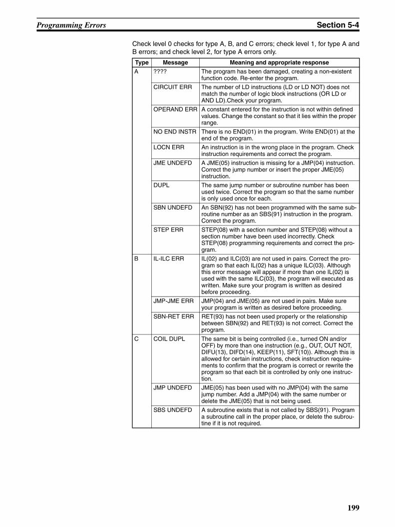
Programming Errors Section 5-4
Check level 0 checks for type A, B, and C errors; check level 1, for type A andB errors; and check level 2, for type A errors only.
Type Message Meaning and appropriate response
A ???? The program has been damaged, creating a non-existent function code. Re-enter the program.
CIRCUIT ERR The number of LD instructions (LD or LD NOT) does not match the number of logic block instructions (OR LD or AND LD).Check your program.
OPERAND ERR A constant entered for the instruction is not within defined values. Change the constant so that it lies within the proper range.
NO END INSTR There is no END(01) in the program. Write END(01) at the end of the program.
LOCN ERR An instruction is in the wrong place in the program. Check instruction requirements and correct the program.
JME UNDEFD A JME(05) instruction is missing for a JMP(04) instruction. Correct the jump number or insert the proper JME(05) instruction.
DUPL The same jump number or subroutine number has been used twice. Correct the program so that the same number is only used once for each.
SBN UNDEFD An SBN(92) has not been programmed with the same sub-routine number as an SBS(91) instruction in the program. Correct the program.
STEP ERR STEP(08) with a section number and STEP(08) without a section number have been used incorrectly. Check STEP(08) programming requirements and correct the pro-gram.
B IL-ILC ERR IL(02) and ILC(03) are not used in pairs. Correct the pro-gram so that each IL(02) has a unique ILC(03). Although this error message will appear if more than one IL(02) is used with the same ILC(03), the program will executed as written. Make sure your program is written as desired before proceeding.
JMP-JME ERR JMP(04) and JME(05) are not used in pairs. Make sure your program is written as desired before proceeding.
SBN-RET ERR RET(93) has not been used properly or the relationship between SBN(92) and RET(93) is not correct. Correct the program.
C COIL DUPL The same bit is being controlled (i.e., turned ON and/or OFF) by more than one instruction (e.g., OUT, OUT NOT, DIFU(13), DIFD(14), KEEP(11), SFT(10)). Although this is allowed for certain instructions, check instruction require-ments to confirm that the program is correct or rewrite the program so that each bit is controlled by only one instruc-tion.
JMP UNDEFD JME(05) has been used with no JMP(04) with the same jump number. Add a JMP(04) with the same number or delete the JME(05) that is not being used.
SBS UNDEFD A subroutine exists that is not called by SBS(91). Program a subroutine call in the proper place, or delete the subrou-tine if it is not required.
199
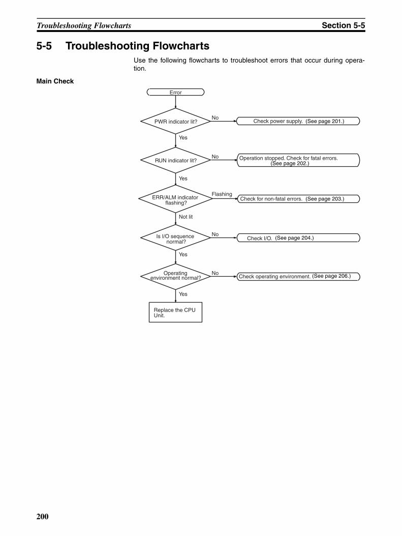
Troubleshooting Flowcharts Section 5-5
5-5 Troubleshooting FlowchartsUse the following flowcharts to troubleshoot errors that occur during opera-tion.
Main Check
Operation stopped. Check for fatal errors.
Check for non-fatal errors.
Error
Replace the CPU Unit.
PWR indicator lit?
RUN indicator lit?
ERR/ALM indicator flashing?
Is I/O sequence normal?
Operating environment normal?
Check I/O.
Check operating environment.
Yes
Check power supply. No
No
No
No
Flashing
Yes
Yes
Not lit
Yes
(See page 201.)
(See page 202.)
(See page 203.)
(See page 204.)
(See page 206.)
200

Troubleshooting Flowcharts Section 5-5
Power Supply Check
PWR indicator not lit.
Replace the CPU Unit.
Is power being supplied?
Is voltage adequate?
Are there any discon-nected connectors or
broken wires?
Connect power supply.
Is PWR indicator lit?
Set supply voltage within acceptable limits.
Is PWR indicator lit?
Connect connectors or replace wires.
End
Yes
No
No Yes
YesNo
No
NoIs PWR indicator lit?
Yes
No
Yes
Yes
201
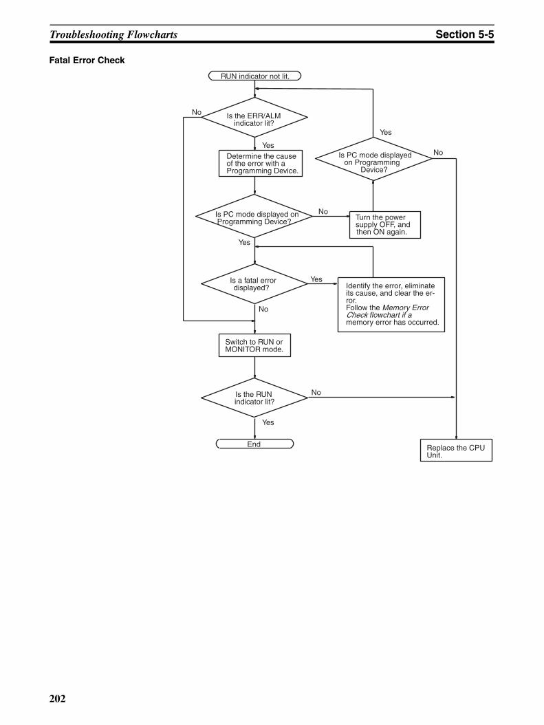
Troubleshooting Flowcharts Section 5-5
Fatal Error Check
Identify the error, eliminate its cause, and clear the er-ror.Follow the Memory Error Check flowchart if amemory error has occurred.
Is the ERR/ALM indicator lit?
Determine the cause of the error with a Programming Device.
End
RUN indicator not lit.
Replace the CPU Unit.
Is PC mode displayed on Programming
Device?
Turn the power supply OFF, and then ON again.
Switch to RUN or MONITOR mode.
No
Yes
Is a fatal error displayed?
Is PC mode displayed on Programming Device?
No
Yes
Yes
No
Is the RUNindicator lit?
No
Yes
Yes
No
202
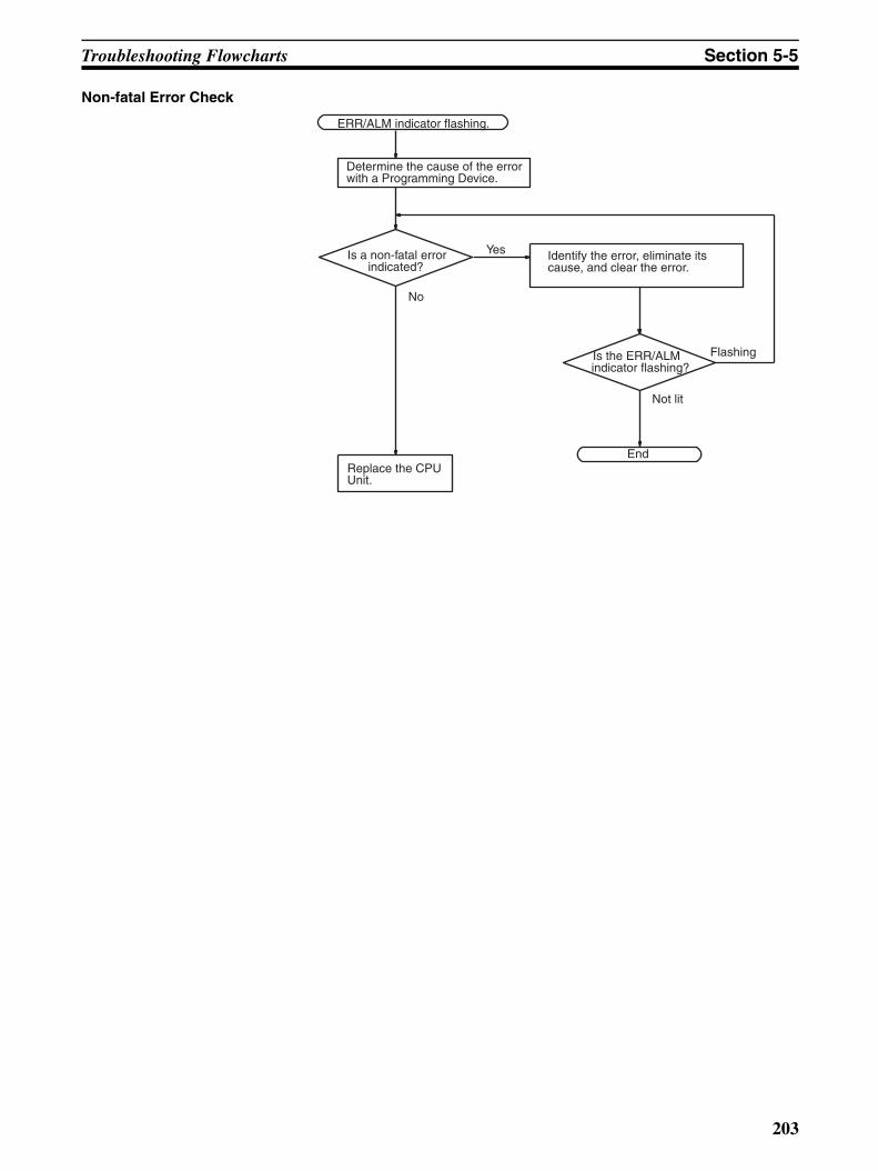
Troubleshooting Flowcharts Section 5-5
Non-fatal Error Check
Identify the error, eliminate its cause, and clear the error.
ERR/ALM indicator flashing.
Is a non-fatal errorindicated?
Is the ERR/ALMindicator flashing?
Replace the CPU Unit.
End
Determine the cause of the error with a Programming Device.
No
Yes
Flashing
Not lit
203

Troubleshooting Flowcharts Section 5-5
I/O Check The I/O check flowchart is based on the following ladder diagram section.
01003
00002(LS1)
00003(LS2)
SOL1 malfunction.
SOL1
01003
Yes
Monitor the ON/OFF status of IR 01003 with a Programming Device.
NoIs theIR 01003 output indicator
operating normally?
Check the voltage at the IR 01003 terminals.
Wire correctly.
Operation OK? Is output wiring correct?
Disconnect the external wires and check the conductivity of each wire.
No
Check output device SOL1.
Operation OK?
Replace the CPU Unit Expansion Unit, or Expansion I/O Unit with the problem.
Yes
No No
Operation OK? NoYes
Yes
ATo next page
Malfunction of SOL1
Yes
204

Troubleshooting Flowcharts Section 5-5
Yes
No
Check the voltage at the IR 00002 and IR 00003 terminals.
Check operation by using a dummy input signal to turn the input ON and OFF.
No
Are the terminal screws loose or con-
nectors disconnected?
Operation OK?
Check input devices LS1 and LS2.
Operation OK?
Wire correctly.
Is input wiring correct?
Tighten the terminal screws and connect connectors.
Return to "start."
Are the IR 00002 and IR 00003 input indi-
cators operating normally?
Replace the CPU Unit, Expansion Unit, or Expansion I/O Unit.
Operation OK?
Yes
Yes
Yes
Yes
NoNo
No
No
No
No
No
Check the voltage at the IR 00002 and IR 00003 terminals.
AFrom previous page
Yes
Replace the CPU Unit, Expansion Unit, or Expansion I/O Unit.
205
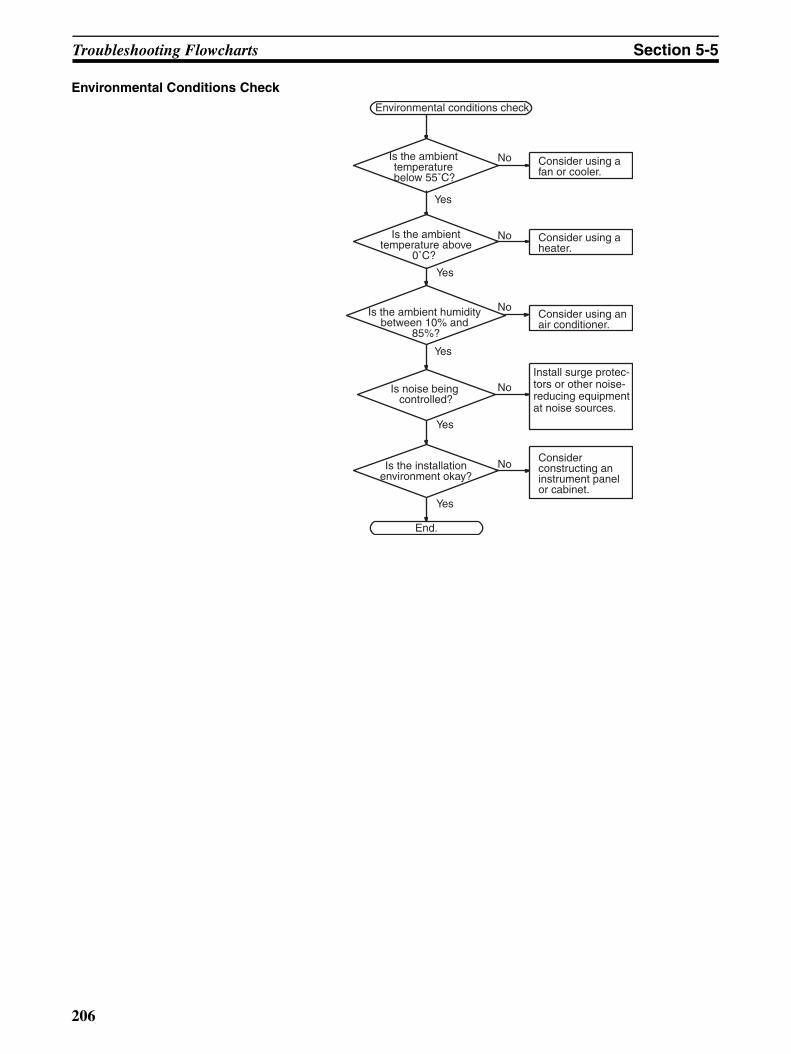
Troubleshooting Flowcharts Section 5-5
Environmental Conditions Check
Consider using a fan or cooler.
Environmental conditions check
Is the ambient temperature below 55˚C?
Is the ambient temperature above
0˚C?
Is noise being controlled?
Is the installationenvironment okay?
Consider using a heater.
Consider using an air conditioner.
Install surge protec-tors or other noise-reducing equipment at noise sources.
Consider constructing an instrument panel or cabinet.
End.
Yes
No
Yes
No
No
No
No
Yes
Yes
Yes
Is the ambient humidity between 10% and
85%?
206
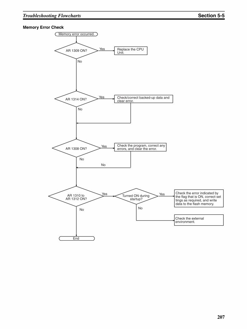
Troubleshooting Flowcharts Section 5-5
Memory Error Check
Memory error occurred.
AR 1309 ON?
AR 1314 ON?
AR 1308 ON?
Replace the CPU Unit.
Check/correct backed-up data and clear error.
Check the program, correct any errors, and clear the error.
End
No
Yes
No
No
Yes
No
Yes
AR 1310 to AR 1312 ON?
Check the error indicated by the flag that is ON, correct settings as required, and write data to the flash memory.
No
Turned ON during startup?
YesYes
Check the external environment.
No
207

Maintenance Inspections Section 5-6
5-6 Maintenance InspectionsIn order for your SYSMAC system to operate in optimum condition, be sure tocarry out daily or periodical inspections.
Inspection Items The main system components of a SYSMAC system are semiconductors, andit contains few components with limited lifetimes. Poor environmental condi-tions, however, can lead to deterioration of the electrical components, makingregular maintenance necessary.
The standard period for maintenance checks is 6 months to 1 year, but morefrequent checks are required if the PC is operated in more demanding condi-tions.
If the criteria are not met, adjust to within the specified ranges.
Note Power supply voltage range:
Required Tools Standard Tools (Required)
• Screwdrivers (Phillips and flat-blade)• Voltage tester or digital voltage meter• Industrial alcohol and a cotton cloth
Measurement Devices (May be Needed)
• Synchroscope• Cathode-ray oscilloscope• Thermometer, hygrometer
Note Do not attempt to disassemble, repair, or modify the PC in any way.
Inspection items Details Criteria Remarks
Power supply Determine whether the voltage fluctuation at the power supply terminals is within specifications.
Within the voltage variation range (see note)
Tester
Environmental con-ditions
Is the ambient temperature inside the panel appropriate?
0 to 55°C Thermometer
Is the ambient humidity inside the panel appropriate?
10% to 90% RH with no con-densation
Hygrometer
Has dirt or dust collected? None Visual inspection
I/O power supply Is the voltage fluctuation measured at the I/O terminals within the standard range?
Each I/O terminal must con-form to the specifications
Tester
Installation status Are all units securely installed? Nothing is loose Phillips screwdriver
Are all connection cables and connectors inserted completely and locked?
Nothing is loose Visual inspection
Are any of the external wiring screws loose? Nothing is loose Phillips screwdriver
Are any of the external wiring cables frayed?
No external abnormalities Visual inspection
Product service life Contact output relay Electrical: Resistance load:150,000 operationsInductive load:100,000 operationsMechanical: 20,000,000 operations
---
Battery (CPM2C-BAT01) 2 years at 25°C ---
Power supply Allowable voltage fluctuation range
100 to 240 VAC (CPM2C-PA201 only) 85 to 264 VAC
24 VDC 20.4 to 26.4 VDC
208

Battery Replacement Section 5-7
5-7 Battery Replacement!WARNING The backup battery may explode, catch fire, or leak if dropped, broken apart,
crushed, short-circuited, recharged, heated to 100°C or higher, or burned.
If power has not been supplied to the PC for some time, turn ON the powersupply for at least 5 minutes to charge the backup capacitor before replacingthe battery.Turn OFF the power supply to the PC before replacing the battery. To preventmemory loss when replacing the Battery for a CPU Unit with a clock, completeBattery replacement within 5 minutes. (CPU Units without a clock will holdmemory for 10 days (at 25°C) using a super capacitor.)A label has been included to remind the user when the battery needs to bereplaced. After replacing the battery, write the next date that the batteryshould be replaced on the label and affix the label in a visible place such asthe inside of the communications port cover.Be sure to dispose of the old battery in accordance with local laws and regula-tions.A CPM2C-BAT01 Backup Battery is built into CPU Units that are equippedwith an internal clock. Replace the battery within two years when used under25°C. When the battery voltage drops, the ERR/ALM indicator will flash andSR 25308 will be turned ON. (Refer to page 197.) In this case, replace thebattery within seven days. Use the procedure below when replacing the bat-tery.
1,2,3... 1. Stop CPM2C operation and turn OFF the power supply.2. Remove the battery cover with a flat-blade screwdriver.
3. Remove the battery and disconnect the battery connector.
Battery cover
209

Battery Replacement Section 5-7
4. Install the new battery. Be sure that the connector is aligned correctly andthe wires are not pinched or kinked when the battery is inserted.
5. To enable the detection of low battery errors, slide the Low Battery Detec-tion Switch towards the front of the Unit and set bits 12 to 15 of DM 6655to “0.”
6. Replace the battery cover.
7. Write the next date that the battery should be replaced on the reminder la-bel. The battery lifetime of the CPU Unit with clock is 2 years at 25°C andthat of the CPU Unit without clock is 5 years at 25°C.
Low Battery Detection Switch
Enable
210
SECTION 6Expansion Memory Unit
This section describes how to use the CPM1-EMU01-V1 Expansion Memory Unit. Follow the handling precautionsand procedures to properly use the Unit.
6-1 Overview . . . . . . . . . . . . . . . . . . . . . . . . . . . . . . . . . . . . . . . . . . . . . . . . . . . . 212
6-1-1 Memory Areas . . . . . . . . . . . . . . . . . . . . . . . . . . . . . . . . . . . . . . . . . 212
6-1-2 Precautions . . . . . . . . . . . . . . . . . . . . . . . . . . . . . . . . . . . . . . . . . . . . 212
6-2 Specifications and Nomenclature . . . . . . . . . . . . . . . . . . . . . . . . . . . . . . . . . . 213
6-2-1 Specifications . . . . . . . . . . . . . . . . . . . . . . . . . . . . . . . . . . . . . . . . . . 213
6-2-2 Nomenclature . . . . . . . . . . . . . . . . . . . . . . . . . . . . . . . . . . . . . . . . . . 213
6-3 Handling . . . . . . . . . . . . . . . . . . . . . . . . . . . . . . . . . . . . . . . . . . . . . . . . . . . . . 214
6-3-1 Mounting/Removing EEPROM . . . . . . . . . . . . . . . . . . . . . . . . . . . . 214
6-3-2 PC Connections . . . . . . . . . . . . . . . . . . . . . . . . . . . . . . . . . . . . . . . . 215
6-3-3 Uploading Programs . . . . . . . . . . . . . . . . . . . . . . . . . . . . . . . . . . . . 216
6-3-4 Downloading Programs . . . . . . . . . . . . . . . . . . . . . . . . . . . . . . . . . . 218
211

Overview Section 6-1
6-1 OverviewThe CPM1-EMU01-V1 Expansion Memory Unit is a program loader for small-size or micro PCs. Using the CPM1-EMU01-V1, simple on-site transfer ofuser programs and data memory between PCs is possible.
Note The “PLC” in the “DOWNLOAD TO PLC” Button indicates PCs (Programma-ble Controllers).
6-1-1 Memory AreasThe memory areas that are uploaded or downloaded vary with the buttonused as shown in the following table.
Note For details on program size, DM area, and the availability of expansioninstructions, refer to the relevant PC manual.
6-1-2 Precautions• Do not attempt to use the CPM1-EMU01-V1 for any applications other
than those described here. Doing so may result in malfunction.• Do not attempt to upload or download data between different types of PC.
Doing so may result in malfunction.• Do not download when the PC is in RUN or MONITOR mode. If down-
loading is performed when the PC is running, it will automatically switch toPROGRAM mode and operation will stop.
• Do not attempt to disassemble, repair, or modify the CPM1-EMU01-V1.Any attempt to do so may result in malfunction, fire, or electric shock.
Uploading
Downloading
Expansion Memory Unit
EEPROM
CPM2C-CN111
CS1W-CN114
CPM2C
CPM2C
CPM2C-CIF01-V1
Button UPLOAD + DM UPLOAD DOWNLOAD TO PLC
Ladder program and expansion instructions
Read from PC to EEPROM.
Read from PC to EEPROM.
All contents of EEPROM written to PC.DM 6144 to 6655 Not affected.
212

Specifications and Nomenclature Section 6-2
• After downloading has been completed, be sure to confirm the user pro-gram, data, and expansion instruction information. Not doing so mayresult in faulty operation.
• Before touching the EEPROM or the CPM1-EMU01-V1, first touch agrounded metallic object to discharge any static build-up. Not doing somay result in malfunction or damage.
6-2 Specifications and Nomenclature
6-2-1 Specifications
Note 1. The EEPROM must be purchased separately.
2. For general specifications, refer to the relevant PC manual.
6-2-2 Nomenclature
Item Specifications
Supported PCs CPM1, CPM1A, CPM2A, CPM2C, SRM1 (-V2), CQM1, CQM1H
Read/Write memory areas User program: 15.2 Kwords max.Data memory: DM 6144 to DM 6655(Read-only DM and PC Setup)Expansion instructions: 18 instructions
Connector Connector compatible with CPM1, CPM1A, CPM2A, SRM1 (-V2), and CQM1 PCs.For CPM2C and CQM1H PCs, connect via CS1W-CN114 or CPM2C-CN111 Connecting Cable.
Communications setting 1 start bit, 7 data bits, even parity, 2 stop bits, 9,600 bps
EEPROM (See note 1.) 256-Kbit EEPROMATMEL:AT28C256-15PCOMRON:EEROM-JD
Current consumption 129 mA max.
Dimensions Main body (not including cables or connectors):57 × 92 × 38 mm (W × H × D)
Weight 200 g max. (not including EEPROM)
Lock LeverFor mounting and removing EEPROM.DOWNLOAD TO PLC ButtonWrites all EEPROM data (ladder programs, data memory etc.) to the PC.UPLOAD + DM ButtonReads PC user program and contents of DM 6144 to DM 6655 to EEPROM.UPLOAD ButtonReads only PC user program to EEPROM.
Lock Lever
Indicator
UPLOAD + DM Button
EEPROM Socket
DOWNLOAD to PLC Button
UPLOAD Button
Peripheral Port Connector
213

Handling Section 6-3
Note The “PLC” in the “DOWNLOAD TO PLC” Button indicates PCs (Programma-ble Controllers).
LED Indicator
6-3 Handling
6-3-1 Mounting/Removing EEPROM
!Caution Do not mount or remove the EEPROM with the CPM1-EMU01-V1 connectedto the PC. Doing so may damage the EEPROM.
Mounting EEPROM
1,2,3... 1. Lift up the lock lever.
2. Straighten the pins on the EEPROM, line up with the socket and lower intothe socket, as shown in the following diagram. If the EEPROM is loose,place it in the center of the socket.
CONNECT (green) ERR (red) Meaning
OFF OFF Not connected to PC (power supply OFF).
ON OFF Connected to a recognized PC.
Blinking OFF Uploading/downloading data.
ON Blinking Host link communications error, retry by user.
OFF ON PC model and EEPROM data not compatible.
OFF Blinking One of the following errors has occurred:An unrecognized PC is connected.An EEPROM error (EEPROM not present, EEPROM defect, or no program to download) or checksum error.
Lift up the lock lever.EEPROM
Insert the EEPROM.
214

Handling Section 6-3
3. Gently hold down the EEPROM and pull down the lock lever.
Removing EEPROM Lift up the lock lever and detach the EEPROM.
6-3-2 PC Connections
!Caution Mount the EEPROM to the CPM1-EMU01-V1 before connecting the CPM1-EMU01-V1 to the PC.
!Caution Do not disconnect the CPM1-EMU01-V1 from the PC when the indicator isblinking green.
CPM2C and CQM1H PCs When connecting to the CPM2C or CQM1H, connect to the peripheral port viathe CPM2C-CN111 or CS1W-CN114 Connecting Cable. Also, set the pins onthe CPU Unit’s DIP switch as follows:
Note If pin 1 on the CPM2C or pin 5 on the CQM1H is OFF, connection is still pos-sible if the peripheral port is set to the defaults.
CPM1, CPM1A, CPM2A, CQM1, and SRM1 (-V2) PCs
When connecting to the CPM1, CPM1A, CPM2A, CQM1 or SRM1 (-V2),insertthe connector into the peripheral port making sure that the connector is ori-ented correctly.
• Insert the connector until it securely locks into place.• Connections are not possible to the RS-232C port or any other port.
Peripheral Port Communications Settings
The peripheral port must be set to the default communications settings shownbelow.
Start bits: 1
Pull down the lock lever.
CPM2C Pin 1: ON (see note)
CQM1H Pin 5: ON (see note)
215

Handling Section 6-3
Data bits: 7
Stop bits: 2
Parity: Even
Baud rate: 9,600 bps
Disconnecting Press the levers on the top and bottom of the connector inwards to unlock theconnector and pull out as shown in the following diagram.
Note Do not attempt to remove the connector by pulling the cable.
6-3-3 Uploading ProgramsLadder programs and the contents of data memory can be uploaded to theEEPROM using the following procedure. The buttons used will determinewhether the contents of data memory are uploaded or not.
Note Use a Phillips screwdriver or other tool with a diameter of 3.0 mm max. and ablade length of 10 mm min. to press the upload button.
Button UPLOAD + DM UPLOAD
Ladder program and expansion instructions
Read from PC to EEPROM.
Read from PC to EEPROM.
DM6144 to 6655 Not affected.
Expansion Memory Unit
Indicator
UPLOAD+DM Button UPLOAD Button
EEPROM
CPM2C-CN111
CS1W-CN114
CPM2C
CPM2C
CPM2C-CIF01-V1
216

Handling Section 6-3
Uploading is possible even if the PC is in RUN or MONITOR mode.
Operation Procedure
10 mm min.
3.0 dia. max.
Start
YesNo
Connect the CPM1-EMU01-V1 to the PC's communications port (peripheral port).
Mount the EEPROM to the CPM1-EMU01-V1.
After 2 or 3 s, check if the indicator is lit green.
See the note on the right.
Select the memory area to be uploaded.
Press the UPLOAD+DM Button.
Press the UPLOAD But-ton.
Check if the indicator is blinking green (indicating that uploading has started).
YesNo
See the note above.
Check if the indicator is lit green (in-dicating that uploading has been suc-cessfully completed).
YesNo
See the note above.
Remove the Expansion Memory Unit from the PC.
End
Mount the EEPROM to the CPM1-EMU01-V1 before connecting to the PC.
Check the orientation of the connector before connecting the CPM1-EMU01-V1.
Note If the indicator is not lit at all, lit red or blinks red, uploading will not be pos- sible. In this case, check the follow- ing items.
• Is the connector properly con- nected?
• Is the EEPROM properly mounted?
• Are the EEPROM specifications cor- rect? • Are the peripheral port communica- tions settings correct?
Upload both the ladder program and DM 6144 to DM 6655.
Upload only the ladder program.
217

Handling Section 6-3
6-3-4 Downloading ProgramsLadder programs and the contents of data memory can be downloaded fromthe EEPROM to the PC using the procedure given below. When downloading,note the following points.
!Caution If the PC is in RUN or MONITOR mode when downloading is started, it willautomatically switch to PROGRAM mode and operation will stop. Confirm thatno adverse effects will occur to the system before downloading. Not doing somay result in unexpected operation.
Note 1. If the PC is in RUN or MONITOR mode, switch the PC mode to PROGRAMmode.
2. Confirm that the program or other data to be downloaded to the PC is com-patible with the PC before downloading.
3. For the CQM1 or CQM1H, when downloading programs that use user-as-signed function codes for expansion instructions, be sure that pin 4 on theCPU Unit’s DIP switch is ON. If these programs are downloaded while thepin is OFF, the assignments for the expansion instructions will return totheir default settings.
4. After downloading has been completed, be sure to confirm the user pro-gram, data, and expansion instructions.
5. When the DOWNLOAD TO PLC Button is pressed, all EEPROM data (lad-der programs, data memory etc.) is written to the PC.
Indicator DOWNLOAD TO PLC Button
Expansion Memory Unit
EEPROM
CPM2C-CN111
CS1W-CN114
CPM2C
CPM2C
CPM2C-CIF01-V1
218
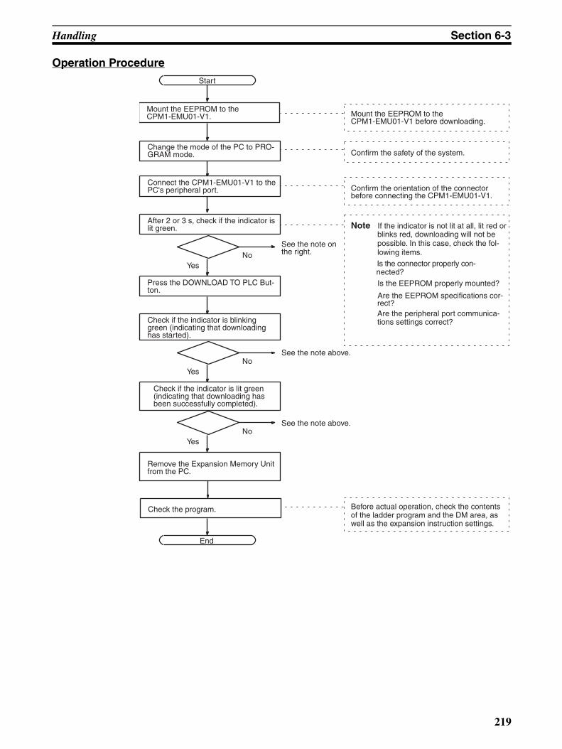
Handling Section 6-3
Operation ProcedureStart
YesNo
Change the mode of the PC to PRO-GRAM mode.
Mount the EEPROM to the CPM1-EMU01-V1.
After 2 or 3 s, check if the indicator is lit green.
See the note on the right.
Press the DOWNLOAD TO PLC But-ton.
Check if the indicator is blinking green (indicating that downloading has started).
YesNo
See the note above.
Check if the indicator is lit green (indicating that downloading has been successfully completed).
YesNo
See the note above.
Remove the Expansion Memory Unit from the PC.
End
Mount the EEPROM to the CPM1-EMU01-V1 before downloading.
Confirm the safety of the system.
Note If the indicator is not lit at all, lit red or blinks red, downloading will not be possible. In this case, check the fol-lowing items.
Is the connector properly con- nected?
Is the EEPROM properly mounted?
Are the EEPROM specifications cor- rect?
Are the peripheral port communica- tions settings correct?
Connect the CPM1-EMU01-V1 to the PC's peripheral port. Confirm the orientation of the connector
before connecting the CPM1-EMU01-V1.
Before actual operation, check the contents of the ladder program and the DM area, as well as the expansion instruction settings.
Check the program.
219

SECTION 7Simple Communications Unit
This section describes the features and functions of the CPM2C-CIF21 Simple Communications Unit, the settingsrequired to use the Unit, and an example application. DM Settings Assignment Sheets are provided in Appendix C torecord data settings.
7-1 Introduction . . . . . . . . . . . . . . . . . . . . . . . . . . . . . . . . . . . . . . . . . . . . . . . . . . 222
7-1-1 Features . . . . . . . . . . . . . . . . . . . . . . . . . . . . . . . . . . . . . . . . . . . . . . 222
7-1-2 System Configuration. . . . . . . . . . . . . . . . . . . . . . . . . . . . . . . . . . . . 222
7-1-3 Processing Component Data . . . . . . . . . . . . . . . . . . . . . . . . . . . . . . 224
7-2 Unit Components and Functions . . . . . . . . . . . . . . . . . . . . . . . . . . . . . . . . . . 228
7-3 Preparation for Operation . . . . . . . . . . . . . . . . . . . . . . . . . . . . . . . . . . . . . . . . 233
7-3-1 Unit Connections . . . . . . . . . . . . . . . . . . . . . . . . . . . . . . . . . . . . . . . 233
7-3-2 Switch Settings. . . . . . . . . . . . . . . . . . . . . . . . . . . . . . . . . . . . . . . . . 234
7-3-3 PC Settings. . . . . . . . . . . . . . . . . . . . . . . . . . . . . . . . . . . . . . . . . . . . 235
7-3-4 Component Settings . . . . . . . . . . . . . . . . . . . . . . . . . . . . . . . . . . . . . 236
7-4 Data Memory (DM) Allocation . . . . . . . . . . . . . . . . . . . . . . . . . . . . . . . . . . . 237
7-4-1 Shared Area . . . . . . . . . . . . . . . . . . . . . . . . . . . . . . . . . . . . . . . . . . . 237
7-4-2 Individual Unit Areas. . . . . . . . . . . . . . . . . . . . . . . . . . . . . . . . . . . . 243
7-5 DM Settings and Component Communications . . . . . . . . . . . . . . . . . . . . . . . 254
7-5-1 DM Settings . . . . . . . . . . . . . . . . . . . . . . . . . . . . . . . . . . . . . . . . . . . 254
7-5-2 Starting Communications with the Components . . . . . . . . . . . . . . . 255
7-6 Precautions for Component Communications . . . . . . . . . . . . . . . . . . . . . . . . 255
7-7 Error Processing . . . . . . . . . . . . . . . . . . . . . . . . . . . . . . . . . . . . . . . . . . . . . . . 256
7-7-1 Fatal Errors (ERR Indicator Lit) . . . . . . . . . . . . . . . . . . . . . . . . . . . 257
7-7-2 Non-fatal Errors (ERR Indicator Flashing) . . . . . . . . . . . . . . . . . . . 257
7-8 Data Refresh Intervals (Reference Data) . . . . . . . . . . . . . . . . . . . . . . . . . . . . 258
7-9 Example Application . . . . . . . . . . . . . . . . . . . . . . . . . . . . . . . . . . . . . . . . . . . 258
7-9-1 System Configuration. . . . . . . . . . . . . . . . . . . . . . . . . . . . . . . . . . . . 259
7-9-2 System Preparation . . . . . . . . . . . . . . . . . . . . . . . . . . . . . . . . . . . . . 260
7-9-3 DM Settings and Component Communications. . . . . . . . . . . . . . . . 261
7-9-4 Ladder Program for DM Settings. . . . . . . . . . . . . . . . . . . . . . . . . . . 265
221

Introduction Section 7-1
7-1 Introduction
7-1-1 FeaturesEasily Transfer Data between the PC and OMRON Components
Ladder programming is not required to transfer data between the PC (CPUUnit) and supported OMRON components because the Simple Communica-tions Unit exchanges data between the PC’s DM area and the OMRON com-ponents.
Connect a Wide Variety of Components
Connects OMRON components equipped with CompoWay/F and SYSWAYcommunications functions including Temperature Controllers, ElectronicTimer/Counters, and Digital Panel Meters.
Monitor All of the Components from the PC
The PVs and status of Temperature Controllers, Electronic Timer/Counters,and Digital Panel Meters can be monitored in the PC’s DM area, so all of theconnected components can be monitored together.
Easily Change Component SVs
Set values in the connected components can be changed just by changing thecorresponding value in the PC’s DM area.
Connect up to 32 Components
Components can be connected with unit numbers 0 to 31.
7-1-2 System ConfigurationComponent Connections The following diagram shows how to connect OMRON components to the
CPM2C CPU Unit through the CPM2C-CIF21 Simple Communications Unit.The Simple Communications Unit uses the CPU Unit’s peripheral port totransfer data with the connected components. Use the Simple Communica-tions Unit’s RS-232C port to connect a PT or computer to the CPM2C’s CPUUnit.
RS-422/RS-485 port
RS-232CRS-422/RS-485 RS-422/RS-485Up to 32 components
*Connect either RS-422/RS-485
RS-422
RS-422/RS-485 cable
B500-AL004
Simple Commu-nications Unit
CPU Unit
Top port Signal con-version
Changes levels between CMOS (CPU Unit) and RS-422 (general-purpose communications components).RS-422 (general-purpose communications components) insulated using DC/DC converter or photocoupler.
Function Conversion between CPU Unit and Host LinkGeneral-purpose communications components are Com-poWay/F or SYSWAY components, which support gen-eral-purpose serial communications.
222
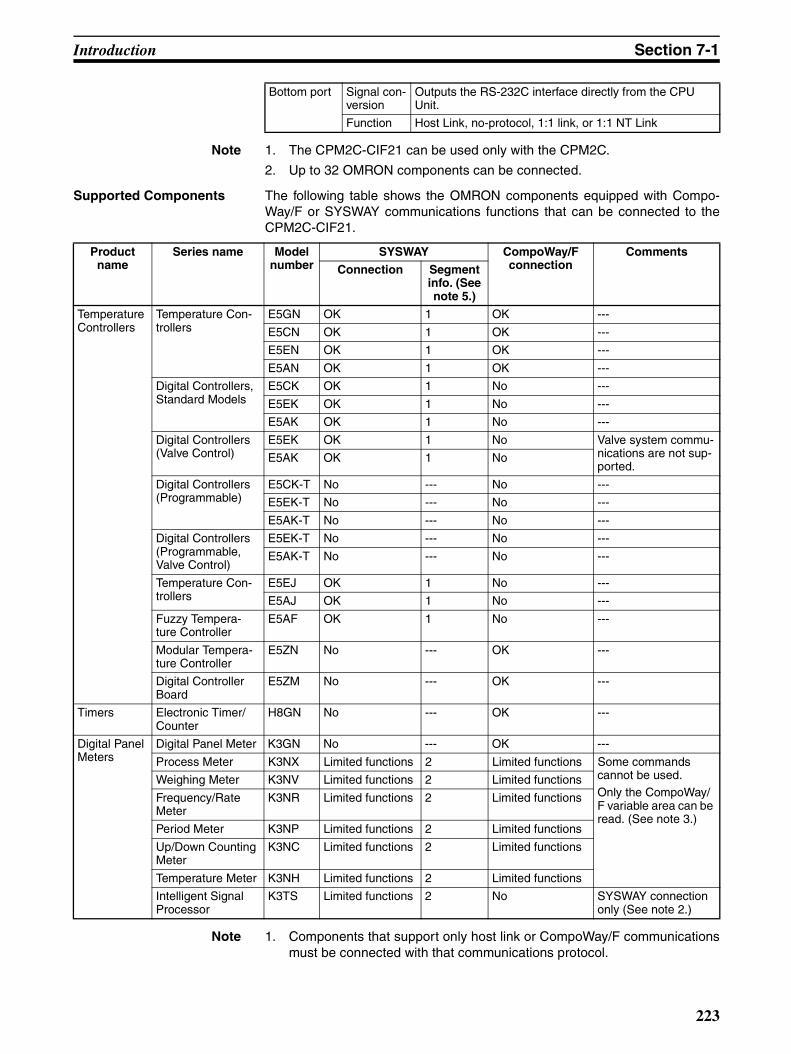
Introduction Section 7-1
Note 1. The CPM2C-CIF21 can be used only with the CPM2C.
2. Up to 32 OMRON components can be connected.
Supported Components The following table shows the OMRON components equipped with Compo-Way/F or SYSWAY communications functions that can be connected to theCPM2C-CIF21.
Note 1. Components that support only host link or CompoWay/F communicationsmust be connected with that communications protocol.
Bottom port Signal con-version
Outputs the RS-232C interface directly from the CPU Unit.
Function Host Link, no-protocol, 1:1 link, or 1:1 NT Link
Product name
Series name Model number
SYSWAY CompoWay/F connection
Comments
Connection Segment info. (See note 5.)
Temperature Controllers
Temperature Con-trollers
E5GN OK 1 OK ---
E5CN OK 1 OK ---
E5EN OK 1 OK ---
E5AN OK 1 OK ---
Digital Controllers, Standard Models
E5CK OK 1 No ---
E5EK OK 1 No ---
E5AK OK 1 No ---
Digital Controllers (Valve Control)
E5EK OK 1 No Valve system commu-nications are not sup-ported.
E5AK OK 1 No
Digital Controllers (Programmable)
E5CK-T No --- No ---
E5EK-T No --- No ---
E5AK-T No --- No ---
Digital Controllers (Programmable, Valve Control)
E5EK-T No --- No ---
E5AK-T No --- No ---
Temperature Con-trollers
E5EJ OK 1 No ---
E5AJ OK 1 No ---
Fuzzy Tempera-ture Controller
E5AF OK 1 No ---
Modular Tempera-ture Controller
E5ZN No --- OK ---
Digital Controller Board
E5ZM No --- OK ---
Timers Electronic Timer/Counter
H8GN No --- OK ---
Digital Panel Meters
Digital Panel Meter K3GN No --- OK ---
Process Meter K3NX Limited functions 2 Limited functions Some commands cannot be used.Only the CompoWay/F variable area can be read. (See note 3.)
Weighing Meter K3NV Limited functions 2 Limited functions
Frequency/Rate Meter
K3NR Limited functions 2 Limited functions
Period Meter K3NP Limited functions 2 Limited functions
Up/Down Counting Meter
K3NC Limited functions 2 Limited functions
Temperature Meter K3NH Limited functions 2 Limited functions
Intelligent Signal Processor
K3TS Limited functions 2 No SYSWAY connection only (See note 2.)
223
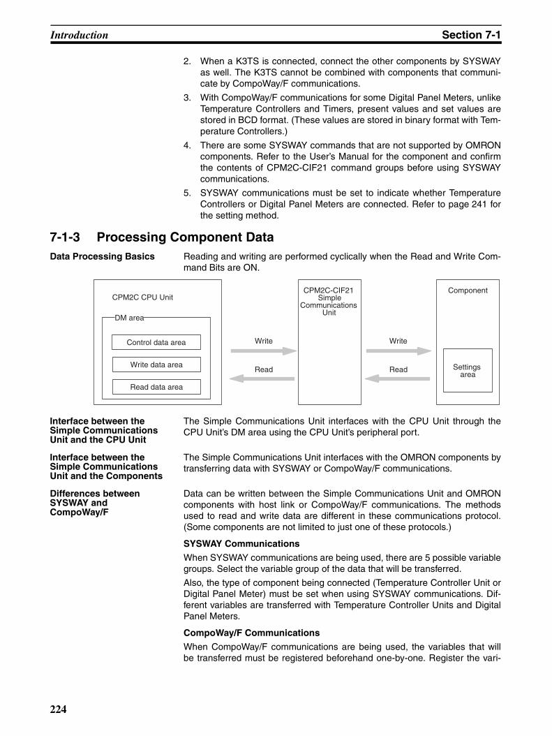
Introduction Section 7-1
2. When a K3TS is connected, connect the other components by SYSWAYas well. The K3TS cannot be combined with components that communi-cate by CompoWay/F communications.
3. With CompoWay/F communications for some Digital Panel Meters, unlikeTemperature Controllers and Timers, present values and set values arestored in BCD format. (These values are stored in binary format with Tem-perature Controllers.)
4. There are some SYSWAY commands that are not supported by OMRONcomponents. Refer to the User’s Manual for the component and confirmthe contents of CPM2C-CIF21 command groups before using SYSWAYcommunications.
5. SYSWAY communications must be set to indicate whether TemperatureControllers or Digital Panel Meters are connected. Refer to page 241 forthe setting method.
7-1-3 Processing Component DataData Processing Basics Reading and writing are performed cyclically when the Read and Write Com-
mand Bits are ON.
Interface between the Simple Communications Unit and the CPU Unit
The Simple Communications Unit interfaces with the CPU Unit through theCPU Unit’s DM area using the CPU Unit’s peripheral port.
Interface between the Simple Communications Unit and the Components
The Simple Communications Unit interfaces with the OMRON components bytransferring data with SYSWAY or CompoWay/F communications.
Differences between SYSWAY and CompoWay/F
Data can be written between the Simple Communications Unit and OMRONcomponents with host link or CompoWay/F communications. The methodsused to read and write data are different in these communications protocol.(Some components are not limited to just one of these protocols.)
SYSWAY Communications
When SYSWAY communications are being used, there are 5 possible variablegroups. Select the variable group of the data that will be transferred.
Also, the type of component being connected (Temperature Controller Unit orDigital Panel Meter) must be set when using SYSWAY communications. Dif-ferent variables are transferred with Temperature Controller Units and DigitalPanel Meters.
CompoWay/F Communications
When CompoWay/F communications are being used, the variables that willbe transferred must be registered beforehand one-by-one. Register the vari-
CPM2C CPU UnitCPM2C-CIF21
SimpleCommunications
Unit
Component
Write
Read
Write
Read Settings area
Control data area
Write data area
Read data area
DM areaDM area
224

Introduction Section 7-1
ables that you want to write/read in the write variable type area and read vari-able type area.
When CompoWay/F communications are being used, only these registeredvariables can be written and read.
225
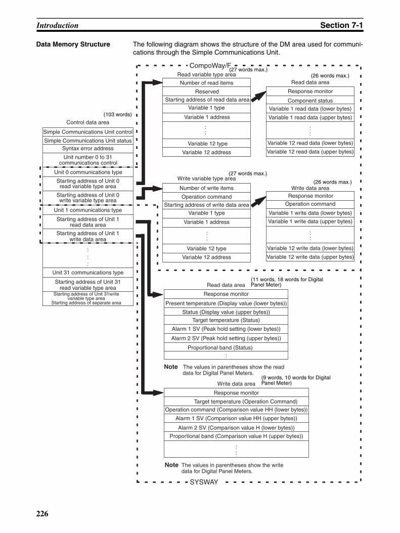
Introduction Section 7-1
Data Memory Structure The following diagram shows the structure of the DM area used for communi-cations through the Simple Communications Unit.
Read variable type area
Number of read items
Reserved
Starting address of read data area
Variable 1 type
Variable 1 address
:
Variable 12 type
Variable 12 address
Write variable type area
Number of write items
Operation command
Starting address of write data area
Variable 1 type
Variable 1 address
::
Variable 12 type
Variable 12 address
Read data area
Write data area
Response monitor
Component status
Variable 1 read data (lower bytes)
Variable 1 read data (upper bytes)
::
Variable 12 read data (lower bytes)
Variable 12 read data (upper bytes)
Response monitor
Operation command
Variable 1 write data (lower bytes)
Variable 1 write data (upper bytes)
::
Variable 12 write data (lower bytes)
Variable 12 write data (upper bytes)
Read data area
Response monitor
Present temperature (Display value (lower bytes))
Status (Display value (upper bytes))
Target temperature (Status)
Alarm 1 SV (Peak hold setting (lower bytes))
Alarm 2 SV (Peak hold setting (upper bytes))
Proportional band (Status)
Note The values in parentheses show the read data for Digital Panel Meters.
Write data area
Response monitor
Target temperature (Operation Command)
Operation command (Comparison value HH (lower bytes))
Alarm 1 SV (Comparison value HH (upper bytes))
Alarm 2 SV (Comparison value H (lower bytes))
Proportional band (Comparison value H (upper bytes))
::
Note The values in parentheses show the write data for Digital Panel Meters.
Control data area
Simple Communications Unit control
Simple Communications Unit statusSyntax error address
Unit number 0 to 31communications control
Unit 0 communications type
Starting address of Unit 0read variable type area
Starting address of Unit 0write variable type area
Unit 1 communications type
Starting address of Unit 1read data area
Starting address of Unit 1write data area
:::
Unit 31 communications type
Starting address of Unit 31read variable type area
CompoWay/F
SYSWAY
:
:
Starting address of Unit 31write variable type area
Starting address of separate area
(103 words)
(27 words max.)(26 words max.)
(27 words max.)
(26 words max.)
(11 words, 18 words for Digital Panel Meter)
(9 words, 10 words for Digital Panel Meter)
226

Introduction Section 7-1
Flow of Data Processing The following flowchart shows the flow of data processing.
Power application
Read DM start area.
Specify Unit 0.
Read Simple Communications Unit control setting.
Simple Communications Unit control setting set to
RUN?
Is there a write command?
Execute an operation command request to the component.
Execute write.
Is there a read command?
Execute read from the component.
Specify next Unit.
Completed 32 Units?
Write Simple Communications Unit status.
NO
NO
NO
YES
YES
NO
YES
YES
227
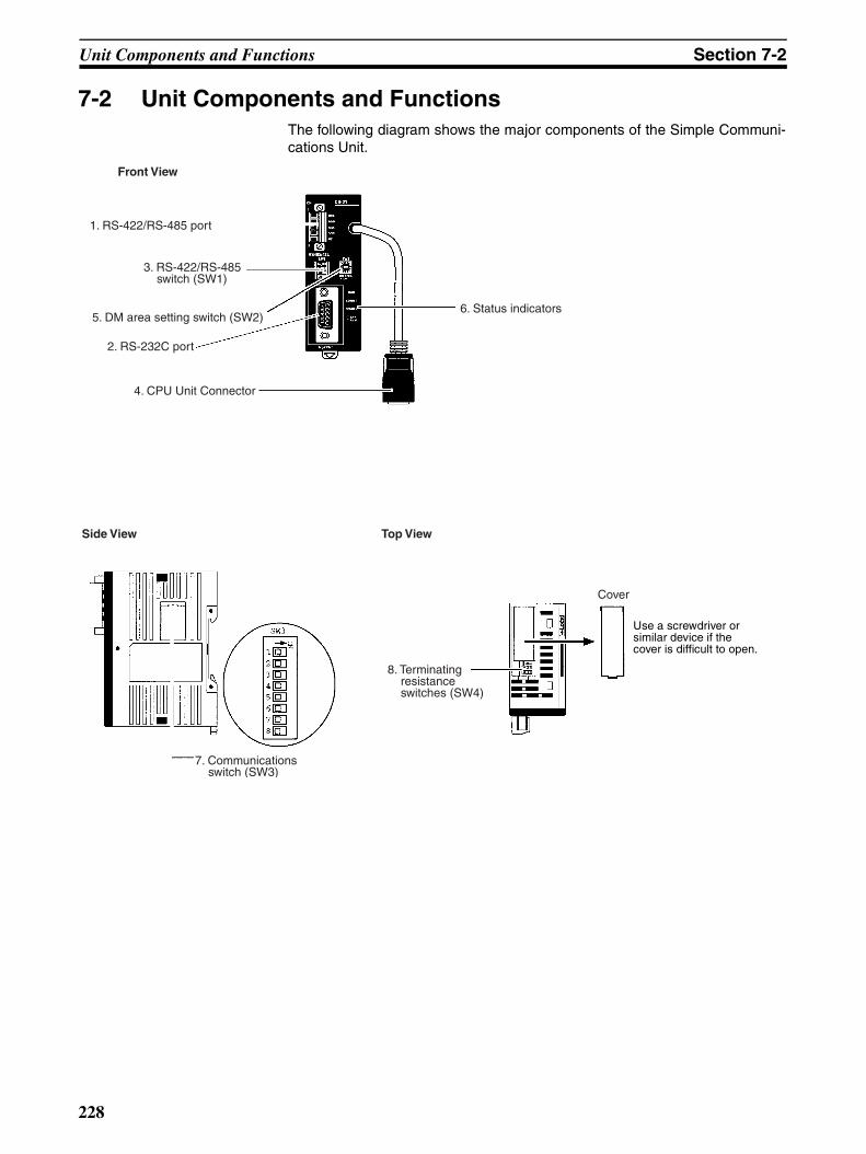
Unit Components and Functions Section 7-2
7-2 Unit Components and FunctionsThe following diagram shows the major components of the Simple Communi-cations Unit.
1. RS-422/RS-485 port
3. RS-422/RS-485 switch (SW1)
2. RS-232C port
4. CPU Unit Connector
5. DM area setting switch (SW2)6. Status indicators
Front View
Side View Top View
8. Terminating resistance switches (SW4)
7. Communications switch (SW3)
Cover
Use a screwdriver or similar device if the cover is difficult to open.
228

Unit Components and Functions Section 7-2
1,2,3... 1. RS-422/RS-485 Port
Connects to Temperature Controllers, Electronic Timer/Counters, and Dig-ital Panel Meters.
RS-485 Connection Example
OMRON componentCPM2C-CIF21
OMRON component
RS-422 Connection Example
OMRON componentCPM2C-CIF21
OMRON component
SDA (− )
SDB (+)
RDA (− )
RDB (+)
RDA (− )
RDB (+)
SDA (− )
SDB (+)
RDA (−
)
RDB (+)
SDA (−)
SDB (+)
RxD
TxD
RxD
TxD
RDA (− )
RDB (+)
SDA (− )
SDB (+)
RDA (− )
RDB (+)
229

Unit Components and Functions Section 7-2
Note RS-422 and RS-485 communications cannot be used together.
2. RS-232C Port
Outputs the CPU Unit’s RS-232C port interface. Connects to an RS-232Cinterface on a computer, PT (Programmable Terminal), etc.
3. RS-422/RS-485 Switch (SW1)
Switches the RS-485 interface and sets RS/CS controls for the RS-485 in-terface.
Note Do not turn ON both SW1-3 and SW1-4 at the same time. Doing so willdestroy internal circuits. The default setting is for RS-485.
RS-422 Interface Block Diagram
TxD
SE
RxD
0 V
C5V5 V
5 V C5V
0 VC0V
C0V
C0V
SW4
C5V
C5V
C5V
SDB
SDASW4
SW1
1 2
RDB
RDASW14
3
5 V
Pin on SW1 RS-422 RS-485
1 OFF ON
2 OFF ON
3 ON OFF
4 OFF ON
Pin Assignments
9 SG8 NC7 NC6 NC
5 CTS4 RTS3 RxD2 TxD1 NC
ON
12
34
ON
12
34
SW1 SW1
RS-422 Setting RS-485 Setting
230

Unit Components and Functions Section 7-2
4. CPU Unit Connector
Connects to CPU Unit communications port.
Note Do not mount or remove connectors for the CPU Unit while power is supplied.Normal communications may not be possible and devices may malfunction.
5. DM Area Setting Switch (SW2)
Sets the starting word in the DM Area that is used to exchange data be-tween the Simple Communications Unit and CPU Unit. The following tableshows the relationship between the rotary-switch setting and starting DMArea word.
Internal Configuration Diagram
CPM2C-CIF21 CPM2C CPU Unit
RS-422/RS-485 port(Terminal block)
RS-232C port(D-Sub connector)
CMOS-level to RS-422 converter
Internalmicro-com-
puter
Peripheral port(CMOS level)
RS-232C port(RS-232C)
Setting Starting word in DM Area
0 DM 0000
1 DM 0100
2 DM 0200
3 DM 0300
4 DM 0400
5 DM 0500
6 DM 0600
7 DM 0700
8 DM 0800
9 DM 0900
A DM 1000
B DM 1100
C DM 1200
D DM 1300
E DM 1400
F DM 1500
SW2
231

Unit Components and Functions Section 7-2
6. Status Indicators
Indicate the operating status of the Simple Communications Unit.
Note a) Fatal errors will stop Unit operation. Remove the cause of the errorand then turn the power supply OFF and back ON.
b) Even non-fatal errors will stop Unit operation. Normal operationwill continue if the cause of the error is remove or if Unit operationis specified from a Programming Device.
7. Communications Switch (SW3)
Sets the baud rates and frame formats for communications between theSimple Communications Unit and the CPU Unit/components. Remove thecover on the side of the Unit to access SW3.
Note a) All pins are set to OFF at the factory. (The default communicationsmethod is normal communications.)
b) Pins 3 to 6 on SW3 are used to set communications between gen-eral-purpose communications components and the Simple Com-munications Unit.
c) Turn OFF pin 7 on SW3. Operation may not be correct if this pin isturned ON.
d) The communications conditions with the CPU Unit are fixed to thefollowing: Data length: 7 bits; Parity: Even; Stop bits: 2.
8. Terminating Resistance Switches (SW4)
Label Status Meaning
RUN Lit Communications established between Simple Communi-cations Unit and CPU Unit. Simple Communications Unit operating.
Not lit Simple Communications Unit not operating.
Flashing Communications between Simple Communications Unit and CPU Unit either not established or interrupted.
ERR/ALM Lit Fatal error occurred. (See note a.)
Flashing Non-fatal error occurred. (See note b.)
Not lit Unit operating normally.
COMM1 Flashing Transferring data between Simple Communications Unit and CPU Unit
Not lit Not transferring data
COMM2 Flashing Transferring data between Simple Communications Unit and connected components
Not lit Not transferring data
Pin Setting OFF ON
1 Baud rate with CPU Unit(See note 2.)
9,600 bps 19,200 bps
2 Baud rate with compo-nents
Normal 9,600 bps 19,200 bps
High-speed 38,400 bps 57,600 bps
3 Data length with components (See note b).)
7 bits 8 bits
4 Parity 1 setting with components Yes None
5 Parity 2 setting with components Even Odd
6 Stop bits with components 2 1
7 Not used. (Always leave pin 7 OFF.) Leave OFF. ---
8 Component communications speed Normal High-speed
ON
12
34
All pins are turned OFF at the factory.
SW3
56
78
232

Preparation for Operation Section 7-3
Turn ON both SW4-1 and SW4-2 if the Simple Communications Unit is atthe end of the RS-422/RS-485 transmission path. Remove the cover onthe top of the Unit to access SW4. If the cover is difficult to remove, use aflat-blade screwdriver or similar tool.
Note a) Both pins are set to OFF at the factory.
b) Terminating ResistanceRS-422: 235 Ω (combined resistance must be 110 Ω min)RS-485: 118 Ω (combined resistance must be 54 Ω min)
7-3 Preparation for OperationThis section describes the procedures to prepare for communications.
7-3-1 Unit ConnectionsConnect the Simple Communications Unit to the PC’s CPU Unit. Power issupplied from the CPU Unit to the Simple Communications Unit through thecommunications cable.
Connect components through their RS-422 or RS-485 interfaces. Up to 32components can be connected.
SW4-1 SW4-2 Function
ON ON Terminating resistance connected.
OFF OFF Terminating resistance disconnected.Resistance not connected
SW4
Resistance connected
Unit connections
Switch settings
PC settings
Component settings
DM settings
Communications with components
233

Preparation for Operation Section 7-3
When the CPM2C-CIF21 Simple Communications Unit is connected to theCPU Unit, a computer or Programmable Terminal can be connected to theRS-232C port on the front of the CPM2C-CIF21. A Programming Consolecannot be connected while the CPM2C-CIF21 is being used because theCPM2C-CIF21 occupies the peripheral port.
7-3-2 Switch SettingsRS-422/RS-485 Switch (SW1)
This switch determines whether components are connected to the SimpleCommunications Unit through an RS-485 interface or RS-422 interface. Whenthe RS-485 interface is being used, set SW1-3 OFF and SW1-4 ON so thatdata is received continuously.
The following table shows the factory default (RS-485) settings.
DM Area Setting Switch (SW2)
Sets the starting word of the range DM Area words used to exchange databetween the Simple Communications Unit and CPU Unit. Rotary switch set-tings 0 to F correspond to starting DM Area words DM 0000 to DM 1500. (Thestarting word is set in 100-word steps.)
The following table shows the factory default setting.
Communications Switch (SW3)
Sets the baud rate for communications between the Simple CommunicationsUnit and the CPU Unit as well as the baud rate and frame format for communi-cations between the Simple Communications Unit and the components. Thebaud rates and frame format set on SW3 must match the settings in the CPUUnit and components.
RS-422 or RS-485
Up to 32 components
Simple Commu-nications Unit
CPU Unit
SW1 pin Default setting Function
1 ON RS-485 interface (2-wire communications)
2 ON
3 OFF Reception permitted after sending of data is com-pleted4 ON
Setting Starting word in DM Area
0 DM 0000
234

Preparation for Operation Section 7-3
In general, set only the baud rate with the CPU Unit and leave the frame for-mat settings set to their defaults (1 start bit, 7 data bits, 2 stop bits, and evenparity.)
The following table shows the factory default settings.
Terminating Resistance Switches (SW4)
Turn ON both SW4-1 and SW4-2 if the Simple Communications Unit is at theend of the RS-422/RS-485 transmission path. The factory default setting isOFF (terminating resistance disconnected) for these switches.
!Caution The power must be turned OFF before changing the settings on SW4-1 andSW4-2. Do not touch SW4 when the power is ON because static electricitymay cause a malfunction.
7-3-3 PC SettingsCommunicating at the Default Baud Rate
Set the CPM2C CPU Unit’s Communications Switch and PC Setup as followswhen communicating at the default baud rate (9,600 bps) between the SimpleCommunications Unit and CPU Unit.
Using Standard Port Settings for the RS-232C Port
Turn ON the CPU Unit’s Communications Switch to use standard communica-tions settings for the communications port. When this switch is ON, the stan-dard settings are used for communications through the RS-232C port andperipheral port regardless of the PC Setup settings in DM 6645 through DM6649 and DM 6650 through DM 6654.
Note The peripheral port’s Host Link node number must be set to 00. Operation willbe disabled if any other value is set.
Using Customized Port Settings for the RS-232C Port
Turn OFF the CPU Unit’s Communications Switch to use allow customizedcommunications settings for the communications port. Communicationsthrough the RS-232C port are governed by the PC Setup settings in DM 6645through DM 6649 and communications through the peripheral port are gov-erned by the PC Setup settings in DM 6650 through DM 6654.
Set DM 6650 to 0000 to specify standard host link communications throughthe peripheral port.
Note The peripheral port’s host link node number must be set to 00. Operation willbe disabled if any other value is set.
Communicating at 19,200 bps
Set the CPM2C CPU Unit’s Communications Switch and PC Setup as followsto communicate at 19,200 bps between the Simple Communications Unit andCPU Unit.
Pin Default setting Function
1 OFF Baud rate with CPU Unit (9,600 bps)
2 OFF Baud rate with components (9,600 bps)
3 OFF Data length with components (7 bits)
4 OFF Parity setting with components (enabled)
5 OFF Parity setting with components (even)
6 OFF Stop bits with components (2 bits)
7 OFF Not used. (Leave OFF.)
8 OFF Component communications speed (normal)
Word Setting Function
DM 6650 0000 Use standard Host Link communications settings.
235
Preparation for Operation Section 7-3
Turn OFF the CPU Unit’s Communications Switch to use allow customizedcommunications settings for the communications port. Communicationsthrough the RS-232C port are governed by the PC Setup settings in DM 6645through DM 6649 and communications through the peripheral port are gov-erned by the PC Setup settings in DM 6650 through DM 6654.
Set DM 6650 and DM 6651 as follows.
Note The peripheral port’s host link node number must be set to 00. Operation willbe disabled if any other value is set.
7-3-4 Component SettingsMake the following settings on the components connected to the Simple Com-munications Unit. Refer to the component’s manuals for details on these set-tings.
Unit Number
Set the component’s unit number between 0 and 31. Do not use a unit numberthat is already set on another component.
Communications Settings
Set the same communications settings that were set for the Simple Communi-cations Unit in 7-3-2 Switch Settings.
Enable Remote Communications Writing
Specify “Enable Communications Writing (Remote)” for the setting mode. If“Disable Communications Writing (Local)” is specified, it won’t be possible tochange the component’s SVs.
Terminating Resistance
Terminating resistance must be set on the component at the end of the RS-422/RS-485 communications cable. Turn on the termination resistance switchon the last component.
Word Setting Function
DM 6650 0001 Use communications settings in DM 6651.
DM 6651 0304 19,200 bps baud rate, 1 start bit, 7 data bits, 2 stop bits, and even parity
236

Data Memory (DM) Allocation Section 7-4
7-4 Data Memory (DM) AllocationThe following diagram shows the usage of the Unit’s allocated DM words.
7-4-1 Shared AreaThe shared area is used to set and monitor values shared by all of the Units(components).
Structure of the Control Data Area
The control data area contains 103 words that are used to control operation ofthe Simple Communications Unit and monitor the Unit’s operating status.Ensure that there are 103 words available for the Control Data Arearegardless of the number of connected Units. The starting DM address isset with Operation Switch SW2. Refer to Operation Switch (SW2) onpage 231 for details.
Shared area
Control data area
Individual Unit areas
Read variable type area
Read data area
Write variable type area
Write data area
Read data area
Write data area
CompoWay/F
SYSWAY
(103 words)
(27 words max.)
(26 words max.)
(27 words max.)
(26 words max.)
(Temperature Controller: 11 wordsDigital Panel Meter: 18 words)
(Temperature Controller: 9 wordsDigital Panel Meter: 10 words)
Offset Function
+0 Simple Communications Unit control
+1 Simple Communications Unit status*1
+2 Syntax error DM address*1
+3 Communications control for Units 0 to 7
+4 Communications control for Units 8 to 15
237

Data Memory (DM) Allocation Section 7-4
Note 1. These words are used to notify the CPU Unit of the Simple Communica-tions Unit’s status.
2. The functions in parentheses are for CompoWay/F communications.
Simple Communications Unit Control (Offset: +0)
+5 Communications control for Units 16 to 23
+6 Communications control for Units 24 to 31
+7 Unit 0 communications type
+8 Starting address of Unit 0 read data area(Starting address of Unit 0 read variable type area*2)
+9 Starting address of Unit 0 write data area(Starting address of Unit 0 write variable type area*2)
+10 Unit 1 communications type
+11 Starting address of Unit 1 read data area(Starting address of Unit 1 read variable type area*2)
+12 Starting address of Unit 1 write data area(Starting address of Unit 1 write variable type area*2)
:
:
:
:
+100 Unit 31 communications type
+101 Starting address of Unit 31 read data area(Starting address of Unit 31 read variable type area*2)
+102 Starting address of Unit 31 write data area(Starting address of Unit 31 write variable type area*2)
Offset Function
Bits Setting Range Function
0 to 3
(Digit 160)
RUN/Stop 1: RUN0: Stop
If this digit is set to 1 after the power is turned ON, the Simple Communica-tions Unit will start communications with components and the CPU Unit. (If a fatal error has occurred, the Unit will not start communications with com-ponents even if this digit is set to 1.)
The Simple Communications Unit will not communicate with components if this digit is set to 0.
4 to 7
(Digit 161)
Communications timeout
0 to 9 (BCD)
Sets the response monitoring time for access from the Simple Communica-tions to connected components. The timeout time is set in multiples of 500 ms ((Set value + 1) × 500 ms). This setting is usually set to 0, which sets a response monitoring time of 500 ms.
8 to 15
(Digits 162 and 163)
Number of con-nected components
00 to 32 (BCD)
Specifies the number of components connected to the Simple Communica-tions Unit. The Simple Communications Unit will not communicate with components if the number of connected components is set to 0.
238

Data Memory (DM) Allocation Section 7-4
Simple Communications Unit Status (Offset: +1)
Syntax Error DM address (Offset: +2)
Error condition Bits Setting Range Function
Error occurred(Bit 15 ON)
0 to 7
(Digits 160 and 161)
Error code 01, 02, or 15
The rightmost 2 digits contain an error code.01: Watchdog timer error (fatal error)
When this error occurs, the Simple Communications Unit will stop all communications and light the ERR indicator after writing the “Simple Communications Unit Status” word.
02: Syntax error (non-fatal error)When this error occurs, the Simple Communications Unit will stop communications with the components and light the ERR indicator after writing the DM address where the error occurred in the “Syntax Error DM Address” word.
15: DM allocation error (fatal error)This error occurs when the Unit attempts to read or write a DM address that does not exist in the CPM2C. After the error occurs, the Simple Communications Unit will stop communi-cations with the components and light the ERR indicator. Check the range of the PC’s DM area and keep DM allocation within that range.
8 to 11
(Digit 162)
Stop flag 0 Operation will stop if an error occurs, and this flag will turn OFF.
12 to 15
(Digit 163)
Error flag 8 A value of 8 (bit 15 ON) indicates that a fatal error has occurred in the Simple Communications Unit.
No error occurred(Bit 15 OFF)
0 to 7
(Digits 160 and 161)
Unit num-ber
00 to 31 (BCD)
Indicates the unit number of the last component with which the communications were completed. The Unit read data from this component and transferred that data to the CPU Unit. These dig-its contain 00 when the power is first turned ON and communica-tions haven’t been completed for any of the components.These digits will also contain 00 in the following cases:
1) The “number of connected components” in the Simple Com-munications Unit Control word (Offset: +0) is set to 00.
2) The “RUN/Stop” setting in the Simple Communications Unit Control word (Offset: +0) is set to 00.
3) “No Unit connected” is set in the Unit’s Communications Type word.
8 to 11
(Digit 162)
Run/Stop flag
0 or 1 This flag will be ON when the Simple Communications Unit is run-ning and OFF when it is stopped.
12 to 15
(Digit 163)
Error flag 0 A value of 0 (bit 15 OFF) indicates that a fatal error has not occurred in the Simple Communications Unit.The Unit will not be able to notify the CPU Unit that a fatal error has occurred in the following cases:1) The CPU Unit is in RUN mode and DM cannot be written.2) An error occurred in communications with the CPU Unit.
3) Program memory is write-protected in the PC Setup (DM 6602).
When one of these 3 errors error occurs, the Simple Communica-tions Unit will stop all communications and light the ERR indicator.
Range Function
0000 to 9999 (BCD)
The Simple Communications Unit indicates the DM address where the syntax error occurred.When two or more syntax errors have been detected, the Unit will indicate the DM address that was detected first.
239
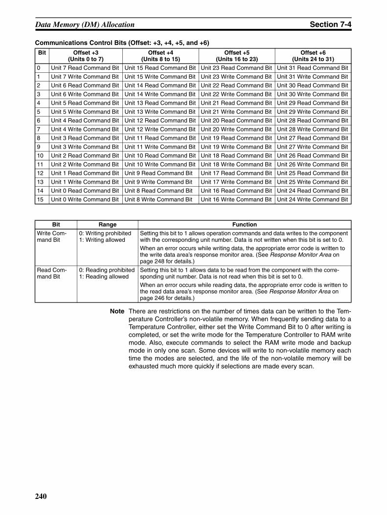
Data Memory (DM) Allocation Section 7-4
Communications Control Bits (Offset: +3, +4, +5, and +6)
Note There are restrictions on the number of times data can be written to the Tem-perature Controller’s non-volatile memory. When frequently sending data to aTemperature Controller, either set the Write Command Bit to 0 after writing iscompleted, or set the write mode for the Temperature Controller to RAM writemode. Also, execute commands to select the RAM write mode and backupmode in only one scan. Some devices will write to non-volatile memory eachtime the modes are selected, and the life of the non-volatile memory will beexhausted much more quickly if selections are made every scan.
Bit Offset +3(Units 0 to 7)
Offset +4(Units 8 to 15)
Offset +5(Units 16 to 23)
Offset +6(Units 24 to 31)
0 Unit 7 Read Command Bit Unit 15 Read Command Bit Unit 23 Read Command Bit Unit 31 Read Command Bit
1 Unit 7 Write Command Bit Unit 15 Write Command Bit Unit 23 Write Command Bit Unit 31 Write Command Bit
2 Unit 6 Read Command Bit Unit 14 Read Command Bit Unit 22 Read Command Bit Unit 30 Read Command Bit
3 Unit 6 Write Command Bit Unit 14 Write Command Bit Unit 22 Write Command Bit Unit 30 Write Command Bit
4 Unit 5 Read Command Bit Unit 13 Read Command Bit Unit 21 Read Command Bit Unit 29 Read Command Bit
5 Unit 5 Write Command Bit Unit 13 Write Command Bit Unit 21 Write Command Bit Unit 29 Write Command Bit
6 Unit 4 Read Command Bit Unit 12 Read Command Bit Unit 20 Read Command Bit Unit 28 Read Command Bit
7 Unit 4 Write Command Bit Unit 12 Write Command Bit Unit 20 Write Command Bit Unit 28 Write Command Bit
8 Unit 3 Read Command Bit Unit 11 Read Command Bit Unit 19 Read Command Bit Unit 27 Read Command Bit
9 Unit 3 Write Command Bit Unit 11 Write Command Bit Unit 19 Write Command Bit Unit 27 Write Command Bit
10 Unit 2 Read Command Bit Unit 10 Read Command Bit Unit 18 Read Command Bit Unit 26 Read Command Bit
11 Unit 2 Write Command Bit Unit 10 Write Command Bit Unit 18 Write Command Bit Unit 26 Write Command Bit
12 Unit 1 Read Command Bit Unit 9 Read Command Bit Unit 17 Read Command Bit Unit 25 Read Command Bit
13 Unit 1 Write Command Bit Unit 9 Write Command Bit Unit 17 Write Command Bit Unit 25 Write Command Bit
14 Unit 0 Read Command Bit Unit 8 Read Command Bit Unit 16 Read Command Bit Unit 24 Read Command Bit
15 Unit 0 Write Command Bit Unit 8 Write Command Bit Unit 16 Write Command Bit Unit 24 Write Command Bit
Bit Range Function
Write Com-mand Bit
0: Writing prohibited1: Writing allowed
Setting this bit to 1 allows operation commands and data writes to the component with the corresponding unit number. Data is not written when this bit is set to 0.When an error occurs while writing data, the appropriate error code is written to the write data area’s response monitor area. (See Response Monitor Area on page 248 for details.)
Read Com-mand Bit
0: Reading prohibited1: Reading allowed
Setting this bit to 1 allows data to be read from the component with the corre-sponding unit number. Data is not read when this bit is set to 0.When an error occurs while reading data, the appropriate error code is written to the read data area’s response monitor area. (See Response Monitor Area on page 246 for details.)
240

Data Memory (DM) Allocation Section 7-4
Unit Communications Type (Offset: +7, +10, +13, ... , +97, and +100)Use the following equation to calculate the offset for a given unit number:
Offset = 7 + (3 × unit number)
Note The command group and segment information settings are valid only whenthe communications protocol is set to SYSWAY. These settings are not validwhen the communications protocol is set to CompoWay/F.
Bits Setting Range Function
0 to 7
(Digits 160 and 161)
Communications protocol
00, 01, or 02
Specifies the communications protocol (SYSWAY or CompoWay/F) of the con-nected component if a component is connected.00: No Unit connected01: SYSWAY02: CompoWay/FA syntax error will occur and this word’s settings will be invalid if a value other than 00, 01, or 02 is specified.
8 to 11
(Digit 162)
Command group(valid with host link only)
1 to 5 (BCD)
This setting is valid only when SYSWAY (01) is specified for the communica-tions protocol. When SYSWAY is specified, the command group determines which values are read/written when reading or writing data.The command group setting will be invalid in the following cases:1) The communications protocol is set to 02 (CompoWay/F).
2) The communications protocol is set to 00 (No Unit connected).3) The communications protocol is set to 01 (SYSWAY), but the command
group setting is not within the allowed range (1 to 5).
12 to 15
(Digit 163)
Segment infor-mation(valid with SYSWAY only)
0, 1, or 2 This setting is valid only when host link (01) is specified for the communica-tions protocol. The segment information specifies whether a Temperature Con-troller or Digital Panel Meter is connected with the host link protocol.
The segment information setting will be invalid in the following cases:1) The communications protocol is set to 02 (CompoWay/F).2) The communications protocol is set to 00 (No Unit connected).
3) The communications protocol is set to 01 (SYSWAY), but the segment information setting is not 1 or 2.
241

Data Memory (DM) Allocation Section 7-4
The following table shows the data that will be read and written for each com-bination of the command group and segment information settings.
Starting Address of Read Data Area or Read Variable Type Area (Offset: +8, +11, ... , +98, and +101)Use the following equation to calculate the offset for a given unit number:
Offset = 8 + (3 × unit number)
Segment information
Access Data Command group
1 2 3 4 5
1: Temperature Controller
Read Present temperature YES YES YES YES YES
Status YES YES YES YES YES
Target temperature YES YES YES YES YES
Alarm 1 SV --- --- YES YES YES
Alarm 2 SV --- --- YES YES YES
Proportional band --- --- --- YES YES
Reset time --- --- --- YES YES
Derivative time --- --- --- YES YES
Heater current --- --- --- --- YES
Heater current status --- --- --- --- YES
Write Target temperature YES YES YES YES YES
Operation command --- YES YES YES YES
Alarm 1 SV --- --- YES YES YES
Alarm 2 SV --- --- YES YES YES
Proportional band --- --- --- YES YES
Reset time --- --- --- YES YES
Derivative time --- --- --- YES YES
Heater burnout detection value --- --- --- --- YES
2: Digital Panel Meter
Read Display value YES YES YES YES YES
Display value status YES YES YES YES YES
Peak hold --- YES YES --- YES
Peak hold status --- YES YES --- YES
Bottom hold --- YES YES --- YES
Bottom hold status --- YES YES --- YES
Comparison value (HH) --- --- --- YES YES
Comparison value (H) --- --- --- YES YES
Comparison value (L) --- --- --- YES YES
Comparison value (LL) --- --- --- YES YES
Write Operation command --- --- YES --- YES
Comparison value (HH) --- --- --- YES YES
Comparison value (H) --- --- --- YES YES
Comparison value (L) --- --- --- YES YES
Comparison value (LL) --- --- --- YES YES
Setting Range Function
Starting Address of Read Data Area(SYSWAY proto-col)
0000 to 9999 BCD
(DM address)
Specifies the starting DM address in the CPU Unit’s DM area where the data read from the component will be stored.A syntax error will occur if the starting address specified in this word is not BCD.
Starting Address of Read Variable Type Area(CompoWay/F protocol)
0000 to 9999 BCD(DM address)
Specifies the starting DM address of the words that show which variables will be read from the component.The data that will be read from the component is determined by the variable type and address written in the variable type area.A syntax error will occur if the starting address specified in this word is not BCD.
242
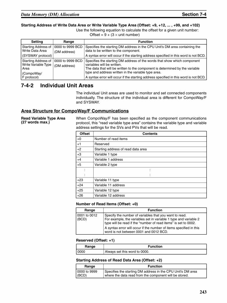
Data Memory (DM) Allocation Section 7-4
Starting Address of Write Data Area or Write Variable Type Area (Offset: +9, +12, ... , +99, and +102)Use the following equation to calculate the offset for a given unit number:
Offset = 9 + (3 × unit number)
7-4-2 Individual Unit AreasThe individual Unit areas are used to monitor and set connected componentsindividually. The structure of the individual area is different for CompoWay/Fand SYSWAY.
Area Structure for CompoWay/F Communications
Read Variable Type Area (27 words max.)
When CompoWay/F has been specified as the component communicationsprotocol, this “read variable type area” contains the variable type and variableaddress settings for the SVs and PVs that will be read.
Number of Read Items (Offset: +0)
Reserved (Offset: +1)
Starting Address of Read Data Area (Offset: +2)
Setting Range Function
Starting Address of Write Data Area(SYSWAY protocol)
0000 to 9999 BCD
(DM address)
Specifies the starting DM address in the CPU Unit’s DM area containing the data to be written to the component.A syntax error will occur if the starting address specified in this word is not BCD.
Starting Address of Write Variable Type Area
(CompoWay/F protocol)
0000 to 9999 BCD(DM address)
Specifies the starting DM address of the words that show which component variables will be written.The data that will be written to the component is determined by the variable type and address written in the variable type area.A syntax error will occur if the starting address specified in this word is not BCD.
Offset Contents
+0 Number of read items
+1 Reserved
+2 Starting address of read data area
+3 Variable 1 type
+4 Variable 1 address
+5 Variable 2 type
::
::
+23 Variable 11 type
+24 Variable 11 address
+25 Variable 12 type
+26 Variable 12 address
Range Function
0001 to 0012 (BCD)
Specify the number of variables that you want to read.For example, the variables set in variable 1 type and variable 2 type will be read if the “number of read items” is set to 0002.A syntax error will occur if the number of items specified in this word is not between 0001 and 0012 BCD.
Range Function
0000 Always set this word to 0000.
Range Function
0000 to 9999 (BCD)
Specifies the starting DM address in the CPU Unit’s DM area where the data read from the component will be stored.
243

Data Memory (DM) Allocation Section 7-4
Variable Types (Offset: +3, +5, ... , +23, and +25)
Use the following equation to calculate the offset for a given variable number:Offset = 1 + (2 × variable number)
Variable Addresses (Offset: +4, +6, ... , +24, and +26)
Use the following equation to calculate the offset for a given variable number:Offset = 2 + (2 × variable number)
Write Variable Type Area (27 words max.)
When CompoWay/F has been specified as the component communicationsprotocol, this “write variable type area” contains the variable type and variableaddress settings for the SVs that will be written.
Number of Write Items (Offset: +0)
Range Function
00C0 to 00CF (Hex)
Sets the type of variable data that you want to read.
The variable types are predetermined in each component, so refer to the component’s manual to find the actual variable type.A syntax error will occur if the variable type specified in this word is not between 00C0 and 00CF Hex.
Range Function
0000 to FFFF (Hex)
Sets the variable address of the data that you want to read.The variable addresses are predetermined in each component, so refer to the component’s manual to find the actual variable address.
Offset Contents
+0 Number of write items
+1 Operation command
+2 Starting address of write data area
+3 Variable 1 type
+4 Variable 1 address
+5 Variable 2 type
::
::
+23 Variable 11 type
+24 Variable 11 address
+25 Variable 12 type
+26 Variable 12 address
Range Function
0000 to 0012 (BCD)
Specify the number of variables that you want to write.For example, the variables set in variable 1 type and variable 2 type will be written if the “number of write items” is set to 0002.
Variables will not be written if the “number of write items” is set to 0000; in this case, only the operation command is valid.A syntax error will occur if the number of items specified in this word is not between 0000 and 0012 BCD.
244

Data Memory (DM) Allocation Section 7-4
Operation Command (Offset: +1)
Note There are restrictions on the number of times data can be written to the Tem-perature Controller’s non-volatile memory. When frequently sending data to aTemperature Controller, either set the Write Command Bit to 0 after writing iscompleted, or set the write mode for the Temperature Controller to RAM writemode. Also, execute commands to select the RAM write mode and backupmode in only one scan. Some devices will write to non-volatile memory eachtime the modes are selected, and the life of the non-volatile memory will beexhausted much more quickly if selections are made every scan.
Starting Address of Write Data Area (Offset: +2)
Variable Types (Offset: +3, +5, ... , +23, and +25)
Use the following equation to calculate the offset for a given variable number:Offset = 1 + (2 × variable number)
Variable Addresses (Offset: +4, +6, ... , +24, and +26)
Use the following equation to calculate the offset for a given variable number:Offset = 2 + (2 × variable number)
Read Data Area(26 words max.)
The starting address of the “read data area” is specified in the “read variabletype area.” This “read data area” stores the variable data read from the com-ponent.
Range Function
0000 or 0001 The write data area’s operation command is disabled when 0000 is specified.The write data area’s operation command is enabled to the compo-nent when 0001 is specified.
A syntax error will occur if the Operation Command is not 0000 or 0001.
Range Function
0000 to 9999 (BCD)
Specifies the starting DM address in the CPU Unit’s DM area con-taining the data that you want to write to the component.
Range Function
00C0 to 00CF (Hex)
Sets the type of variable data that you want to write.The variable types are predetermined in each component, so refer to the component’s manual to find the actual variable type.A syntax error will occur if the variable type specified in this word is not between 00C0 and 00CF Hex.
Range Function
0000 to FFFF (Hex)
Sets the variable address of the data that you want to write.The variable addresses are predetermined in each component, so refer to the component’s manual to find the actual variable address.
Offset Contents
+0 Response monitor
+1 Component status
+2 Variable 1 read data (lower bytes)
+3 Variable 1 read data (upper bytes)
+4 Variable 2 read data (lower bytes)
+5 Variable 2 read data (upper bytes)
::
::
+22 Variable 11 read data (lower bytes)
245

Data Memory (DM) Allocation Section 7-4
Response Monitor Area (Offset: +0)
This area contains the results of communications when communicating withthe component to read variables.
1,2,3... 1. End Code = 00When the function’s end code is 00, the “response monitor area” containsthe response code.
2. End Code ≠ 00When an error occurs and the function’s end code is a value other than 00,the “response monitor area” contains the end code (error code). The valueof FF in the first two digits indicates that an error occurred during transmis-sion of the CompoWay/F command.
Note A Not Defined Error can occur when using SYSWAY communica-tions with a general-purpose communications component. An exam-ple of a Not Defined Error would be when a Temperature Controllerwas connected via SYSWAY and the Temperature Controller was setfor ON/OFF control, yet a command was sent to read the proportion-al band, integral time, and derivative time. A Not Defined Error wouldoccur in this case.
+23 Variable 11 read data (upper bytes)
+24 Variable 12 read data (lower bytes)
+25 Variable 12 read data (upper bytes)
Offset Contents
Response code Meaning
0000 Indicates normal completion.
0401 Unsupported command
1001 Command length too long
1002 Command length too short
1101 Area type error
1103 Starting address out-of-range error
1104 End address out-of-range error
1003 Number of elements doesn’t match amount of data
110B Response length too long
1100 Parameter error
2203 Operating error
Error code Meaning
FF04 Address overflow
FF0D Could not execute command
FF10 Parity error
FF11 Framing error
FF12 Overrun error
FF13 BCC error
FF14 Format error
FF15 Numeric data error
FF16 Sub-address error/Not defined error (IC) (See note.)
FF18 Frame length error
FF97 Response data BCC error
246

Data Memory (DM) Allocation Section 7-4
3. Timeout error occurred
Component Status (Offset: +1)
Read Data (Offset: +2, +4, ... , +22, and +24)
The read data is contained in two words starting at offset 2 × n (n = variablenumber.)
The variable data read from a component can have a value ranging from0000 0000 to FFFF FFFF. The read data will be 0000 0000 if a communica-tions error occurred. The following example shows the contents of the readdata area when a communications error occurred while reading the variable 2read data.
• Response Monitor Area: Contains the error code.• Status: Contains the controller status.• Read data 1: Contains the data read from the component.• Read data 2: Contains 0000 0000.• Remaining read items: Contain 0000 0000.
Note 1. The decimal point position has to be managed by the user since the com-ponent’s decimal point position is not transferred in CompoWay/F commu-nications.
2. BCD format is used with Digital Panel Meters (K3N@). For details, refer tothe manual for the model used.
Write Data Area(26 words max.)
The starting address of the “write data area” is specified in the “write variabletype area.” Store the variable data that you want to write to the component inthis “write data area.”
Timeout code Meaning
E999 Indicates that there was no response from the compo-nent.
163 162 161 160
Component status
Contain the controller status of the component.
Offset Range Function
2 × n
(n = variable number)
0000 to FFFF (Hex)
Contains the lower (rightmost) two bytes of the data. Data is expressed in 2’s complement signed binary format.
(2 × n) + 1
(n = variable number)
0000 to FFFF (Hex)
Contains the upper (leftmost) two bytes of the data. Data is expressed in 2’s complement signed binary format.
Offset Contents
+0 Response monitor
+1 Operation Command
+2 Variable 1 write data (lower bytes)
+3 Variable 1 write data (upper bytes)
+4 Variable 2 write data (lower bytes)
+5 Variable 2 write data (upper bytes)
::
::
+22 Variable 11 write data (lower bytes)
+23 Variable 11 write data (upper bytes)
+24 Variable 12 write data (lower bytes)
+25 Variable 12 write data (upper bytes)
247
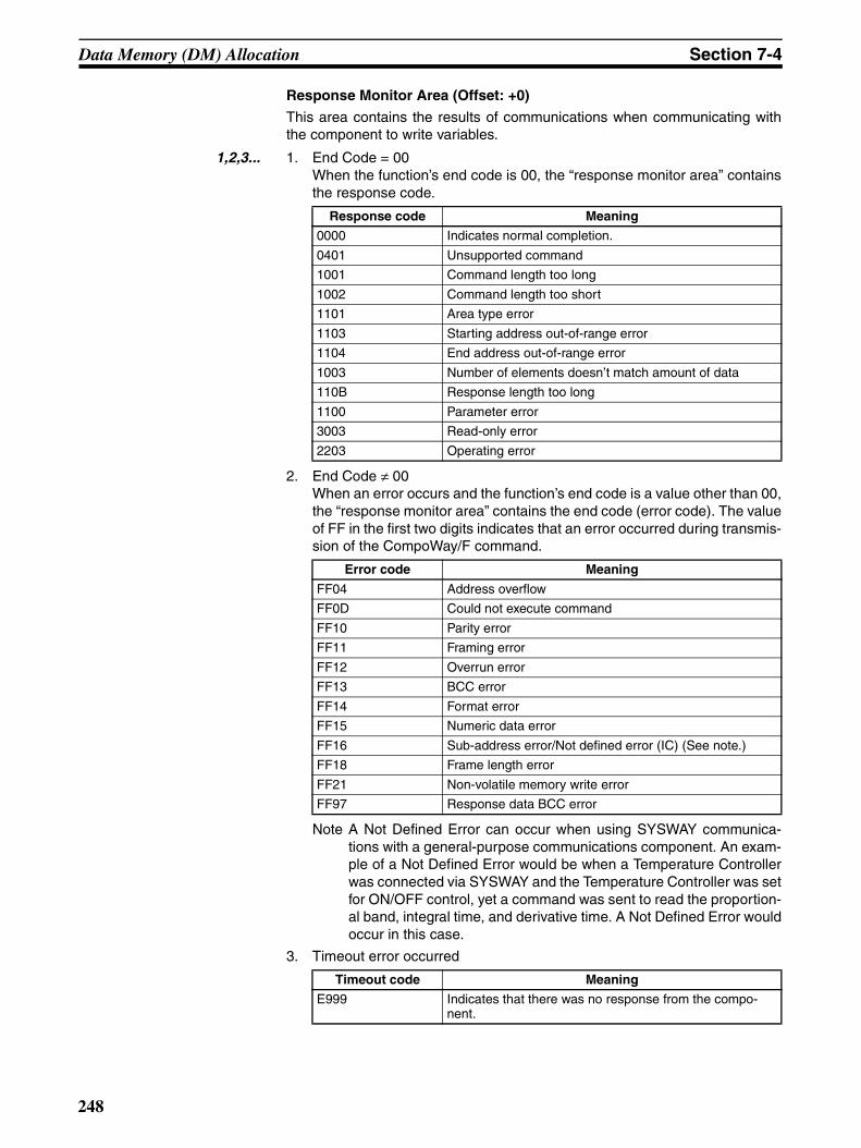
Data Memory (DM) Allocation Section 7-4
Response Monitor Area (Offset: +0)
This area contains the results of communications when communicating withthe component to write variables.
1,2,3... 1. End Code = 00When the function’s end code is 00, the “response monitor area” containsthe response code.
2. End Code ≠ 00When an error occurs and the function’s end code is a value other than 00,the “response monitor area” contains the end code (error code). The valueof FF in the first two digits indicates that an error occurred during transmis-sion of the CompoWay/F command.
Note A Not Defined Error can occur when using SYSWAY communica-tions with a general-purpose communications component. An exam-ple of a Not Defined Error would be when a Temperature Controllerwas connected via SYSWAY and the Temperature Controller was setfor ON/OFF control, yet a command was sent to read the proportion-al band, integral time, and derivative time. A Not Defined Error wouldoccur in this case.
3. Timeout error occurred
Response code Meaning
0000 Indicates normal completion.
0401 Unsupported command
1001 Command length too long
1002 Command length too short
1101 Area type error
1103 Starting address out-of-range error
1104 End address out-of-range error
1003 Number of elements doesn’t match amount of data
110B Response length too long
1100 Parameter error
3003 Read-only error
2203 Operating error
Error code Meaning
FF04 Address overflow
FF0D Could not execute command
FF10 Parity error
FF11 Framing error
FF12 Overrun error
FF13 BCC error
FF14 Format error
FF15 Numeric data error
FF16 Sub-address error/Not defined error (IC) (See note.)
FF18 Frame length error
FF21 Non-volatile memory write error
FF97 Response data BCC error
Timeout code Meaning
E999 Indicates that there was no response from the compo-nent.
248
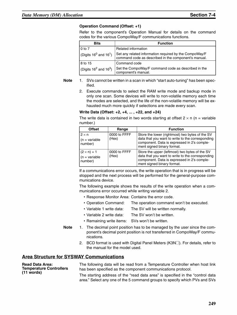
Data Memory (DM) Allocation Section 7-4
Operation Command (Offset: +1)
Refer to the component’s Operation Manual for details on the commandcodes for the various CompoWay/F communications functions.
Note 1. SVs cannot be written in a scan in which “start auto-tuning” has been spec-ified.
2. Execute commands to select the RAM write mode and backup mode inonly one scan. Some devices will write to non-volatile memory each timethe modes are selected, and the life of the non-volatile memory will be ex-hausted much more quickly if selections are made every scan.
Write Data (Offset: +2, +4, ... , +22, and +24)
The write data is contained in two words starting at offset 2 × n (n = variablenumber.)
If a communications error occurs, the write operation that is in progress will bestopped and the next process will be performed for the general-purpose com-munications device.
The following example shows the results of the write operation when a com-munications error occurred while writing variable 2.
• Response Monitor Area: Contains the error code.• Operation Command: The operation command won’t be executed.• Variable 1 write data: The SV will be written normally.• Variable 2 write data: The SV won’t be written.• Remaining write items: SVs won’t be written.
Note 1. The decimal point position has to be managed by the user since the com-ponent’s decimal point position is not transferred in CompoWay/F commu-nications.
2. BCD format is used with Digital Panel Meters (K3N@). For details, refer tothe manual for the model used.
Area Structure for SYSWAY Communications
Read Data Area:Temperature Controllers(11 words)
The following data will be read from a Temperature Controller when host linkhas been specified as the component communications protocol.
The starting address of the “read data area” is specified in the “control dataarea.” Select any one of the 5 command groups to specify which PVs and SVs
Bits Function
0 to 7
(Digits 160 and 161)
Related information
Set any related information required by the CompoWay/F command code as described in the component’s manual.
8 to 15
(Digits 162 and 163)
Command codeSet the CompoWay/F command code as described in the component’s manual.
Offset Range Function
2 × n(n = variable number)
0000 to FFFF (Hex)
Store the lower (rightmost) two bytes of the SV data that you want to write to the corresponding component. Data is expressed in 2’s comple-ment signed binary format.
(2 × n) + 1
(n = variable number)
0000 to FFFF (Hex)
Store the upper (leftmost) two bytes of the SV data that you want to write to the corresponding component. Data is expressed in 2’s comple-ment signed binary format.
249

Data Memory (DM) Allocation Section 7-4
will be read, although 11 DM words will be allocated to the read data arearegardless of the command group selected.
Response Monitor Area (Offset: +0)
The structure of the response monitor area is the same whether SYSWAY orCompoWay/F communications are used. See Response Monitor Area onpage 246 for details on the response monitor area.
Read Data (Offset: +1, +3, +4, +5, +6, +7, +8, and +9)
Each word of data read from the Temperature Controller has a value rangingfrom 0000 to FFFF, which is 2’s complement signed binary data. The word willcontain 0000 if a communications error occurred. The following exampleshows the contents of the read data when a communications error occurredwhile reading the target temperature in command group 1.
• Response Monitor Area: Contains the error code.• Present temperature: Contains data read from Temperature Controller.• Status: Contains status read from Temperature Control-
ler.• Target temperature: Contains 0000.
Note The decimal point position has to be managed by the user since the Tempera-ture Controller’s decimal point position is not transferred in host link (X format)communications.
Status (Offset: +2 and +10)
The read data area’s +2 offset word contains the status when reading thepresent temperature. The +10 offset word contains the heater current statuswhen reading the heater current. Refer to the Temperature Controller’s Opera-tion Manual for details on the status values.
Read Data Area:Digital Panel Meters(18 words)
The following data will be read from a Digital Panel Meter when SYSWAY hasbeen specified as the component communications protocol.
The starting address of the “read data area” is specified in the “control dataarea.” Select any one of the 5 command groups to specify which PVs and SVswill be read, although 18 DM words will be allocated to the read data arearegardless of the command group selected.
Offset Data Command group
1 2 3 4 5
+0 Response monitor Read Read Read Read Read
+1 Present temperature Read Read Read Read Read
+2 Status Read Read Read Read Read
+3 Target temperature Read Read Read Read Read
+4 Alarm 1 SV --- --- Read Read Read
+5 Alarm 2 SV --- --- Read Read Read
+6 Proportional band --- --- --- Read Read
+7 Reset time --- --- --- Read Read
+8 Derivative time --- --- --- Read Read
+9 Heater current monitor --- --- --- --- Read
+10 Heater current status --- --- --- --- Read
Offset Data Command group
1 2 3 4* 5
+0 Response monitor area Read Read Read Read Read
+1 and +2 Display value Read Read Read Read Read
250
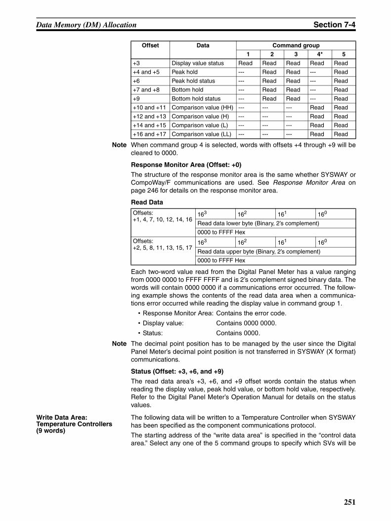
Data Memory (DM) Allocation Section 7-4
Note When command group 4 is selected, words with offsets +4 through +9 will becleared to 0000.
Response Monitor Area (Offset: +0)
The structure of the response monitor area is the same whether SYSWAY orCompoWay/F communications are used. See Response Monitor Area onpage 246 for details on the response monitor area.
Read Data
Each two-word value read from the Digital Panel Meter has a value rangingfrom 0000 0000 to FFFF FFFF and is 2’s complement signed binary data. Thewords will contain 0000 0000 if a communications error occurred. The follow-ing example shows the contents of the read data area when a communica-tions error occurred while reading the display value in command group 1.
• Response Monitor Area: Contains the error code.• Display value: Contains 0000 0000.• Status: Contains 0000.
Note The decimal point position has to be managed by the user since the DigitalPanel Meter’s decimal point position is not transferred in SYSWAY (X format)communications.
Status (Offset: +3, +6, and +9)
The read data area’s +3, +6, and +9 offset words contain the status whenreading the display value, peak hold value, or bottom hold value, respectively.Refer to the Digital Panel Meter’s Operation Manual for details on the statusvalues.
Write Data Area:Temperature Controllers(9 words)
The following data will be written to a Temperature Controller when SYSWAYhas been specified as the component communications protocol.
The starting address of the “write data area” is specified in the “control dataarea.” Select any one of the 5 command groups to specify which SVs will be
+3 Display value status Read Read Read Read Read
+4 and +5 Peak hold --- Read Read --- Read
+6 Peak hold status --- Read Read --- Read
+7 and +8 Bottom hold --- Read Read --- Read
+9 Bottom hold status --- Read Read --- Read
+10 and +11 Comparison value (HH) --- --- --- Read Read
+12 and +13 Comparison value (H) --- --- --- Read Read
+14 and +15 Comparison value (L) --- --- --- Read Read
+16 and +17 Comparison value (LL) --- --- --- Read Read
Offset Data Command group
1 2 3 4* 5
Offsets:+1, 4, 7, 10, 12, 14, 16
163 162 161 160
Read data lower byte (Binary, 2’s complement)
0000 to FFFF Hex
Offsets:+2, 5, 8, 11, 13, 15, 17
163 162 161 160
Read data upper byte (Binary, 2’s complement)
0000 to FFFF Hex
251

Data Memory (DM) Allocation Section 7-4
written, although 9 DM words will be allocated to the write data area regard-less of the command group selected.
Response Monitor Area (Offset: +0)
The structure of the response monitor area is the same whether SYSWAY orCompoWay/F communications are used. See Response Monitor Area onpage 248 for details on the response monitor area.
Write Data (Offset: +1, +3, +4, +5, +6, +7, and +8)
Set the words of data to be written to the Temperature Controller as 2’s com-plement signed binary data.
If a communications error occurs while writing data, the remaining write datawill not be written and the next process for the general-purpose communica-tions device will be executed. The error code will be written to the responsemonitor area.
The following example shows the results of the write operation when a com-munications error occurred while writing the target temperature in commandgroup 2.
• Response Monitor Area: Contains the error code.• Target temperature: The SV won’t be written.• Operation Command: The operation command won’t be written.
Note The decimal point position has to be managed by the user since the Tempera-ture Controller’s decimal point position is not transferred in SYSWAY (X for-mat) communications.
Operation Command (Offset: +2)
Store the operation command code (0000 to 0005) in this word. When a com-mand group that includes the operation command is selected, the corre-sponding operation command will be sent to the Temperature Controller.
Note 1. SVs cannot be written in a scan in which “start auto-tuning” has been spec-ified.
2. Starting and stopping auto-tuning is possible for E5EK, E5AK, and E5AFmodels only.
Offset Data Command group
1 2 3 4 5
+0 Response monitor area Written Written Written Written Written
+1 Target temperature Written Written Written Written Written
+2 Operation command --- Written Written Written Written
+3 Alarm 1 SV --- --- Written Written Written
+4 Alarm 2 SV --- --- Written Written Written
+5 Proportional band --- --- --- Written Written
+6 Reset time --- --- --- Written Written
+7 Derivative time --- --- --- Written Written
+8 Heater burnout detection value
--- --- --- --- Written
Command code Operation
0000 Don’t perform operation command. (No operation)
0001 Stop auto-tuning.
0002 Start auto-tuning.
0003 Select backup mode.
0004 Select RAM write mode.
0005 Hold the Run/Adjust SV.
252

Data Memory (DM) Allocation Section 7-4
3. When selecting the RAM write mode or backup mode, program the selec-tion operation so that it is executed only one scan. Some components writeto EEPROM when this selection is made, and if it is made each scan, theservice live of the EEPROM will be affected.
4. There are restrictions on the number of times data can be written to theTemperature Controller’s non-volatile memory. When frequently sendingdata to a Temperature Controller, either set the Write Command Bit to 0 af-ter writing is completed, or set the write mode for the Temperature Control-ler to RAM write mode. Also, execute commands to select the RAM writemode and backup mode in only one scan. Some devices will write to non-volatile memory each time the modes are selected, and the life of the non-volatile memory will be exhausted much more quickly if selections aremade every scan.
Write Data Area:Digital Panel Meters(10 words)
The following data will be written to a Digital Panel Meter when host link hasbeen specified as the component communications protocol.
The starting address of the “write data area” is specified in the “control dataarea.” Select any one of the 5 command groups to specify which SVs will bewritten, although 10 DM words will be allocated to the write data area regard-less of the command group selected.
Response Monitor Area (Offset: +0)
The structure of the response monitor area is the same whether host link orCompoWay/F communications are used. See Response Monitor Area onpage 248 for details on the response monitor area.
Write Data
Set the words of data to be written to the Digital Panel Meter as 2’s comple-ment signed binary data.
If a communications error occurs while writing data, the remaining write datawill not be written and the next process for the general-purpose communica-tions device will be executed. The error code will be written to the responsemonitor area.
The following example shows the results of the write operation when a com-munications error occurred while writing comparison value (H) in commandgroup 4.
• Response Monitor Area: Contains the error code.• Comparison value (HH): The SV will be written normally.• Comparison value (H): The SV won’t be written.
Offset Data Command group
1 2 3 4 5
+0 Response monitor area Written Written Written Written Written
+1 Operation command --- --- Written --- Written
+2 and +3 Comparison value (HH) --- --- --- Written Written
+4 and +5 Comparison value (H) --- --- --- Written Written
+6 and +7 Comparison value (L) --- --- --- Written Written
+8 and +9 Comparison value (LL) --- --- --- Written Written
Offsets:+2, 4, 6, 8
163 162 161 160
Write data lower byte (Binary, 2’s complement)
0000 to FFFF Hex
Offsets:+3, 5, 7, 9
163 162 161 160
Write data upper byte (Binary, 2’s complement)
0000 to FFFF Hex
253

DM Settings and Component Communications Section 7-5
• Comparison value (L): The SV won’t be written.• Comparison value (LL): The SV won’t be written.
Note The decimal point position has to be managed by the user since the DigitalPanel Meter’s decimal point position is not transferred in SYSWAY (X format)communications.
Operation Command (Offset: +2)
Store the operation command code (0000 to 0004) in this word. When a com-mand group that includes the operation command is selected, the corre-sponding operation command will be sent to the Temperature controller.
Note 1. When selecting the RAM write mode or backup mode, program the selec-tion operation so that it is executed only one scan. Some components writeto EEPROM when this selection is made, and if it is made each scan, theservice live of the EEPROM will be affected.
2. There are restrictions on the number of times data can be written to theTemperature Controller’s non-volatile memory. When frequently sendingdata to a Temperature Controller, either set the Write Command Bit to 0 af-ter writing is completed, or set the write mode for the Temperature Control-ler to RAM write mode. Also, execute commands to select the RAM writemode and backup mode in only one scan. Some devices will write to non-volatile memory each time the modes are selected, and the life of the non-volatile memory will be exhausted much more quickly if selections aremade every scan.
7-5 DM Settings and Component CommunicationsThis section explains the basic procedures required to communicate with con-nected components. Refer to 7-4 Data Memory (DM) Allocation for details onDM settings and setting procedures.
Write the following program sections in the user program to establish commu-nications with the connected components.
7-5-1 DM SettingsVerify that the components that you want to connect are supported by theCPM2C-CIF21. Determine whether the components will communicate bySYSWAY or CompoWay/F communications.
Write the following program sections at the beginning of the user program sothat the DM settings are made when the CPM2C is turned ON.
1,2,3... 1. Parameter Settings in the Control Data Area
• Set the number of connected components (32 max.)
• When using SYSWAY, set each component’s segment information.
• When using SYSWAY, select and set a command group that containsthe values that you want to read or write.
• Set the communications protocol.
• When using SYSWAY, set the starting addresses of each component’sread/write areas.
Command code Operation
0000 Don’t perform operation command. (No operation)
0001 Reset.
0002 Select backup mode.
0003 Select RAM write mode.
0004 Hold the Setting/Adjust values.
254

Precautions for Component Communications Section 7-6
• When using CompoWay/F, set the starting addresses of each compo-nent’s read/write variable type areas.
2. When using CompoWay/F, set the variable type and variable address ofeach variable that you want to read or write. (Set this information in theread/write variable type area.)
3. When writing data, set the data that you want to write in the write data area.
7-5-2 Starting Communications with the ComponentsUse the following procedure to start communications with the components.
1,2,3... 1. Set the rightmost digit of the “Simple Communications Unit control” wordin the Control Data Area (the RUN/Stop digit) to 1 (RUN).
2. Turn ON the Read Command Bit or Write Command Bit of the desiredcomponent. (These bits are in the Control Data Area with word offsets +3,+4, +5, and +6. See Communications Control Bits on page 240.)
Changes to the following values are recognized only when the Simple Com-munications Unit control word’s RUN/Stop digit is switched from Stop to RUN.When one of these values has been changed, switch the Simple Communica-tions Unit from RUN to Stop and then back to RUN again.
• Segment information• Command group• Communications protocol• Starting addresses of read/write data areas• Starting addresses of read/write variable type areas
Note Refer to Simple Communications Unit Control on page 238 for details on theRUN/Stop Digit.
7-6 Precautions for Component CommunicationsObserve the following precautions when communicating with components.
Time Required to Refresh Read/Write Data
The time required to refresh read or write data varies with the CPM2C’s cycletime. Moreover, the refreshing interval is not fixed.
Establishment of Communications with the CPU Unit
Power is supplied to the Simple Communications Unit and the CPU Unit at thesame time. After the power is turned ON, the Simple Communications Unit willattempt to establish communications with the CPU Unit and will wait for aresponse. If there is no response from the CPU Unit after retrying for 2 min-utes, a fatal error will occur and the ERR indicator will light.
Operating Mode of the CPU Unit
It is not possible for the Simple Communications Unit to write data to the CPUUnit if the CPU Unit is in RUN mode. Just before writing data, the CPU Unit’soperating mode is checked with the STATUS READ host link command. If theCPU Unit is found to be in RUN mode, the mode is changed to MONITORmode with the STATUS WRITE host link command so that the data can bewritten.
When a data write error occurs because the CPU Unit was changed to RUNmode from a Programming Device, the Simple Communications Unit willattempt to change the operating mode and write data twice. If these retriesfail, a fatal error will occur and the ERR indicator will light.
Switching the Simple Communications Unit from “Stop” to “RUN”
The Simple Communications Unit must be switched from Stop to RUN inorder to validate any changes made in Control Data Area words +7 through+102. After editing these words, always switch the Unit from RUN to Stop and
255
Error Processing Section 7-7
then back to RUN again. Refer to Simple Communications Unit Control onpage 238 for details on the RUN/Stop Digit.
Note The Communications Control Area (Read and Write Command Bits) and theCompoWay/F Read and Write Variable Type Areas are read every scan, so itis not necessary to switch the Unit from Stop to RUN after these areas havebeen edited.
Syntax Errors When a syntax error occurs in the Simple Communications Unit, switch theUnit from RUN to Stop, correct the cause of the syntax error, and then switchthe Unit back to RUN.
Syntax errors are non-fatal errors that are cleared by switching the Unit fromStop to RUN. Non-fatal errors are not cleared just by eliminating the cause ofthe error.
DM Allocation Errors When a DM allocation error occurs, it is possible that the DM allocationexceeds the boundary of the CPM2C’s DM Area. After correcting the DM allo-cation, reset the power supply for the Simple Communications Unit.
DM allocation errors are fatal errors that are cleared by resetting the powersupply. Fatal errors are not cleared just by eliminating the cause of the error.
Delaying the Communications Response with Components
The communications timeout setting must be extended if you are using a sys-tem configuration that causes a significant delay in the communicationsresponse between the Simple Communications Unit and the components,such as wireless communications between the Unit and components. Thecommunications timeout setting can be set in multiples of 500 ms, up to themaximum monitoring time of 5.0 s. Set a monitoring time appropriate for yoursystem.
Note 1. Under normal conditions, it is not necessary to change the communica-tions timeout setting. In general use a setting of 0, which sets a responsemonitoring time of 500 ms. Refer to Simple Communications Unit Controlon page 238 for details on the communications timeout setting.
2. There are restrictions on the number of times data can be written to theTemperature Controller’s non-volatile memory. When frequently sendingdata to a Temperature Controller, either set the Write Command Bit to 0 af-ter writing is completed, or set the write mode for the Temperature Control-ler to RAM write mode. Also, execute commands to select the RAM writemode and backup mode in only one scan. Some devices will write to non-volatile memory each time the modes are selected, and the life of the non-volatile memory will be exhausted much more quickly if selections aremade every scan.
7-7 Error ProcessingThe Simple Communications Unit can detect two kinds of errors: fatal errorscause the ERR indicator to light and non-fatal errors cause the ERR indicatorto flash. The following tables show the likely causes of these errors and theerror processing required.
256

Error Processing Section 7-7
7-7-1 Fatal Errors (ERR Indicator Lit)
Note DM allocation errors are indicated in the Simple Communications Unit statusword. (Refer to Simple Communications Unit Status on page 239 for details.)
7-7-2 Non-fatal Errors (ERR Indicator Flashing)
Note 1. Details on communications errors can be found in the Response MonitorArea. See Response Monitor Area on page 246 for details on errors thatoccur while reading or page 248 for details on errors that occur while writ-ing.
2. Syntax errors are indicated in the Simple Communications Unit statusword. (Refer to Simple Communications Unit Status on page 239 for de-tails.)
Error Likely cause and correction
Communications cannot be estab-lished with the CPU Unit.
Check the communications baud rate and other communications settings in the CPU Unit and Simple Communications Unit. Correct the settings and turn ON the Simple Communications Unit again.
There was a communications error with the CPU Unit.
Noise can cause communications errors. If noise is suspected, use cables and wiring methods that will reduce noise in the communications lines and turn ON the Simple Communications Unit again.
Cannot write data while the CPU Unit is in RUN mode.
Check whether the CPU Unit is in RUN mode. If so, switch the CPU Unit to MONITOR mode or PROGRAM mode and turn ON the power again.
A watchdog timer error occurred. Watchdog timer errors are indicated in the Simple Communications Unit status word. (Refer to Simple Communications Unit Status on page 239.)
It is possible for noise to affect the Simple Communications Unit’s pro-cessing. If noise is suspected, take steps to reduce noise around the Unit or shield the Unit.The watchdog timer error can be cleared by turning the power supply OFF and then ON again.
DM allocation error (See note.) The DM allocation may exceed the boundary of the CPM2C’s DM Area.
When a DM allocation error is detected, error code “15” is written to the Simple Communications Unit Status word (see page 239).To restore normal operation, correct the DM allocation and switch the Unit from RUN to Stop and then back to RUN again. Refer to Simple Communi-cations Unit Control on page 238 for details on the RUN/Stop Digit.
Error Likely cause and correction
There was a communications error with a component. (See note 1.)
Check whether the communications settings in the components match the settings in the Simple Communications Unit. Correct the settings if neces-sary. Normal operation will be restored when the cause of the communica-tions error is corrected.
Noise can cause communications errors. If noise is suspected, use cables and wiring methods that will reduce noise in the communications lines. Normal operation will be restored when the cause of the communications error is corrected.
Syntax error (See note 2.) A syntax error occurs when there is an error in the DM settings.
When a syntax error is detected, error code “02” is written to the Simple Communications Unit Status word (see page 239) and the DM word address is written to the Syntax Error DM Address word (see page 239).
To restore normal operation, correct the setting in the indicated DM word and switch the Unit from RUN to Stop and then back to RUN again. Refer to Simple Communications Unit Control on page 238 for details on the RUN/Stop Digit.
257
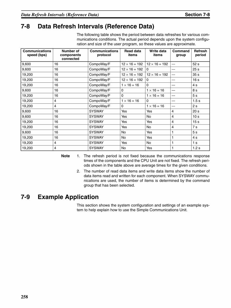
Data Refresh Intervals (Reference Data) Section 7-8
7-8 Data Refresh Intervals (Reference Data)The following table shows the period between data refreshes for various com-munications conditions. The actual period depends upon the system configu-ration and size of the user program, so these values are approximate.
Note 1. The refresh period is not fixed because the communications responsetimes of the components and the CPU Unit are not fixed. The refresh peri-ods shown in the table above are average times for the given conditions.
2. The number of read data items and write data items show the number ofdata items read and written for each component. When SYSWAY commu-nications are used, the number of items is determined by the commandgroup that has been selected.
7-9 Example ApplicationThis section shows the system configuration and settings of an example sys-tem to help explain how to use the Simple Communications Unit.
Communications speed (bps)
Number of components connected
Communications protocol
Read data items
Write data items
Command group
Refresh period
9,600 16 CompoWay/F 12 × 16 = 192 12 × 16 = 192 --- 52 s
9,600 16 CompoWay/F 12 × 16 = 192 0 --- 25 s
19,200 16 CompoWay/F 12 × 16 = 192 12 × 16 = 192 --- 35 s
19,200 16 CompoWay/F 12 × 16 = 192 0 --- 16 s
19,200 16 CompoWay/F 1 × 16 = 16 0 --- 4 s
9,600 16 CompoWay/F 0 1 × 16 = 16 --- 8 s
19,200 16 CompoWay/F 0 1 × 16 = 16 --- 5 s
19,200 4 CompoWay/F 1 × 16 = 16 0 --- 1.5 s
19,200 4 CompoWay/F 0 1 × 16 = 16 --- 2 s
9,600 16 SYSWAY Yes Yes 4 20 s
9,600 16 SYSWAY Yes No 4 10 s
19,200 16 SYSWAY Yes Yes 4 15 s
19,200 16 SYSWAY Yes No 4 7 s
9,600 16 SYSWAY No Yes 1 5 s
19,200 16 SYSWAY No Yes 1 4 s
19,200 4 SYSWAY Yes No 1 1 s
19,200 4 SYSWAY No Yes 1 1.2 s
258

Example Application Section 7-9
7-9-1 System ConfigurationThe example system has three E5CN Temperature Controllers connected tothe Simple Communications Unit.
DM Allocation The DM allocation is shown in the following table.
Communications with CPU Unit
Communications speed: 19,200 bps
Communications with Components
The following settings are used for the RS-485 communications:
Unit number 0 Connected by CompoWay/F. Constantly monitors the PV. The target temperature is changed
to100°C by input condition 0005.
Unit number 2 Connected by SYSWAY.The Simple Communications Unit
reads command group 1 only.
Unit number 3 Connected by SYSWAY. The Simple Communications Unit writes
a target temperature of 200°C when the power is turned ON and thereafter just reads command group 1.
Simple Commu-nications Unit
CPU Unit
•••
••
••
Unit settings Area name DM words
All (shared) Control Data Area DM 0000 to DM 0102
Unit 0 Unit 0 Read Variable Type Area DM 0150 to DM 0154
Unit 0 Write Variable Type Area DM 0160 to DM 0164
Unit 0 Read Data Area DM 0170 to DM 0173
Unit 0 Write Data Area DM 0180 to DM 0183
Unit 2 Unit 2 Read Data Area DM 0200 to DM 0210
Unit 2 Write Data Area DM 0220 to DM 0228
Unit 3 Unit 3 Read Data Area DM 0240 to DM 0250
Unit 3 Write Data Area DM 0260 to DM 0268
Item Setting
Communications speed 19,200 bps
Data bits 7 bits
Parity Even
Stop bits 2 bits
259

Example Application Section 7-9
7-9-2 System PreparationRefer to SECTION 3 Installation and Wiring and make the following prepara-tions.
1,2,3... 1. Connect the Units.
2. Set switches.
3. Make required settings in the PC.
4. Make required settings in the components.
260
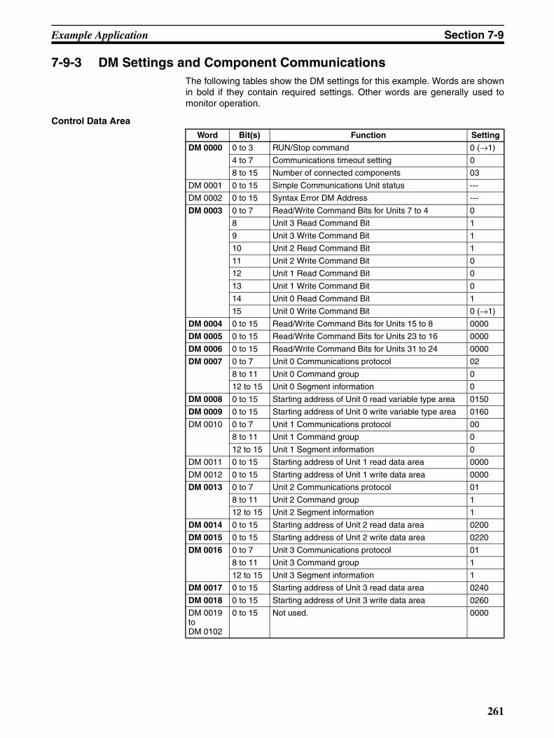
Example Application Section 7-9
7-9-3 DM Settings and Component CommunicationsThe following tables show the DM settings for this example. Words are shownin bold if they contain required settings. Other words are generally used tomonitor operation.
Control Data Area
Word Bit(s) Function Setting
DM 0000 0 to 3 RUN/Stop command 0 (→1)
4 to 7 Communications timeout setting 0
8 to 15 Number of connected components 03
DM 0001 0 to 15 Simple Communications Unit status ---
DM 0002 0 to 15 Syntax Error DM Address ---
DM 0003 0 to 7 Read/Write Command Bits for Units 7 to 4 0
8 Unit 3 Read Command Bit 1
9 Unit 3 Write Command Bit 1
10 Unit 2 Read Command Bit 1
11 Unit 2 Write Command Bit 0
12 Unit 1 Read Command Bit 0
13 Unit 1 Write Command Bit 0
14 Unit 0 Read Command Bit 1
15 Unit 0 Write Command Bit 0 (→1)
DM 0004 0 to 15 Read/Write Command Bits for Units 15 to 8 0000
DM 0005 0 to 15 Read/Write Command Bits for Units 23 to 16 0000
DM 0006 0 to 15 Read/Write Command Bits for Units 31 to 24 0000
DM 0007 0 to 7 Unit 0 Communications protocol 02
8 to 11 Unit 0 Command group 0
12 to 15 Unit 0 Segment information 0
DM 0008 0 to 15 Starting address of Unit 0 read variable type area 0150
DM 0009 0 to 15 Starting address of Unit 0 write variable type area 0160
DM 0010 0 to 7 Unit 1 Communications protocol 00
8 to 11 Unit 1 Command group 0
12 to 15 Unit 1 Segment information 0
DM 0011 0 to 15 Starting address of Unit 1 read data area 0000
DM 0012 0 to 15 Starting address of Unit 1 write data area 0000
DM 0013 0 to 7 Unit 2 Communications protocol 01
8 to 11 Unit 2 Command group 1
12 to 15 Unit 2 Segment information 1
DM 0014 0 to 15 Starting address of Unit 2 read data area 0200
DM 0015 0 to 15 Starting address of Unit 2 write data area 0220
DM 0016 0 to 7 Unit 3 Communications protocol 01
8 to 11 Unit 3 Command group 1
12 to 15 Unit 3 Segment information 1
DM 0017 0 to 15 Starting address of Unit 3 read data area 0240
DM 0018 0 to 15 Starting address of Unit 3 write data area 0260
DM 0019 toDM 0102
0 to 15 Not used. 0000
261

Example Application Section 7-9
Unit 0 Read Variable Type Area (CompoWay/F)
Note Variable type 00C0 and variable address 0000 indicate the PV.
Unit 0 Write Variable Type Area (CompoWay/F)
Note Variable type 00C1 and variable address 0003 indicate the target tempera-ture.
Unit 0 Read Data Area (CompoWay/F)
Note The Temperature Controller’s PV is read to DM 0172 and DM 0173 becausethe “Unit 0 read variable type area” specified the PV.
Unit 0 Write Data Area (CompoWay/F)
Note 1. The operation command is set to 0000 (disabled) in the Unit 0 write vari-able type area, so the command code and related information are notused.
2. Sets the hexadecimal equivalent of the target temperature (100°C) whichis the variable that was registered in the Unit 0 write variable type area.
Word Bit(s) Function Setting
DM 0150 0 to 15 Number of read items 0001
DM 0151 0 to 15 Reserved ---
DM 0152 0 to 15 Starting address of read data area 0170
DM 0153 0 to 15 Variable 1 type 00C0
DM 0154 0 to 15 Variable 1 address 0000
Word Bit(s) Function Setting
DM 0160 0 to 15 Number of write items 0001
DM 0161 0 to 15 Operation Command 0000
DM 0162 0 to 15 Starting address of write data area 0180
DM 0163 0 to 15 Variable 1 type 00C1
DM 0164 0 to 15 Variable 1 address 0003
Word Bit(s) Function
DM 0170 0 to 15 Response monitor areaContains 0000 when component communications are normal.
DM 0171 0 to 15 StatusThe component’s status is read to this word.
DM 0172 0 to 15 Variable 1 read data (lower bytes)
DM 0173 0 to 15 Variable 1 read data (upper bytes)
Word Bit(s) Function Setting
DM 0180 0 to 15 Response monitor areaContains 0000 when communications with the com-ponent are normal.
---
DM 0181 0 to 7 Operation Command: command code*1 ---
8 to 15 Operation Command: related information*1 ---
DM 0182 0 to 15 Variable 1 write data (lower bytes)*2 0064
DM 0183 0 to 15 Variable 1 write data (upper bytes)*2 0000
262

Example Application Section 7-9
Unit 2 Read Data Area (SYSWAY)
The segment information is 1 and the command group is 1.
Note The entire Unit 2 read data area is refreshed even though command group 1is selected and only the values in DM 0200 to DM 0202 are read from thecomponent. (The contents of DM 0204 to DM 0210 are cleared to 0000.)When communicating with a Temperature Controller through SYSWAY,always allocate 11 words to the read data area even if the selected commandgroup limits the number of words actually read.
Unit 2 Write Data Area (SYSWAY)
The segment information is 1 and the command group is 1.
Allocate words DM 0220 through DM 0228 to the Unit 2 write data area. In thisexample data isn’t written to Unit 2, so it isn’t necessary to set data in the Unit2 write data area.
Word Function
DM 0200 Response monitor areaContains 0000 when component communications are normal.
DM 0201 Present temperatureContains the PV in 2’s complement signed binary format.
DM 0202 StatusContains the status when the PV was read.
DM 0203 Target temperature (See note.)Contains the target temperature in 2’s complement signed binary format.
DM 0204 Alarm 1 SV (See note.)Contains the alarm 1 set value in 2’s complement signed binary format.
DM 0205 Alarm 2 SV (See note.)Contains the alarm 2 set value in 2’s complement signed binary format.
DM 0206 Proportional band (See note.)Contains the proportional band setting in binary.
DM 0207 Reset time (See note.)Contains the reset time setting in binary.
DM 0208 Derivative time (See note.)Contains the derivative time setting in binary.
DM 0209 Heater current monitor (See note.)Contains the heater’s electrical current in binary.
DM 0210 Heater current status (See note.)Contains the status when the heater’s electrical current was read.
263

Example Application Section 7-9
Unit 3 Read Data Area (SYSWAY)
The segment information is 1 and the command group is 1.
Note The entire Unit 3 read data area is refreshed even though command group 1is selected and only the values in DM 0240 to DM 0242 are read from thecomponent. (The contents of DM 0244 to DM 0250 are cleared to 0000.)When communicating with a Temperature Controller through SYSWAY,always allocate 11 words to the read data area even if the selected commandgroup limits the number of words actually read.
Unit 3 Write Data Area (SYSWAY)
The segment information is 1 and the command group is 1.
Note It is possible to write just the target temperature by selecting command group1.When communicating with a Temperature Controller through SYSWAY,
Word Function
DM 0240 Response monitor areaContains 0000 when component communications are normal.
DM 0241 Present temperatureContains the PV in 2’s complement signed binary format.
DM 0242 StatusContains the status when the PV was read.
DM 0243 Target temperature (See note.)Contains the target temperature in 2’s complement signed binary format.
DM 0244 Alarm 1 SV (See note.)Contains the alarm 1 set value in 2’s complement signed binary format.
DM 0245 Alarm 2 SV (See note.)Contains the alarm 2 set value in 2’s complement signed binary format.
DM 0246 Proportional band (See note.)Contains the proportional band setting in binary.
DM 0247 Reset time (See note.)Contains the reset time setting in binary.
DM 0248 Derivative time (See note.)Contains the derivative time setting in binary.
DM 0249 Heater current monitor (See note.)Contains the heater’s electrical current in binary.
DM 0250 Heater current status (See note.)Contains the status when the heater’s electrical current was read.
Word Function
DM 0260 Response monitor areaContains 0000 when component communications are normal.
DM 0261 Target temperature00C8 (200°C)
DM 0262 Operation command (See note.)0000
DM 0263 Alarm 1 SV (See note.)Set the alarm 1 set value in 2’s complement signed binary format.
DM 0264 Alarm 2 SV (See note.)Set the alarm 2 set value in 2’s complement signed binary format.
DM 0265 Proportional band (See note.)Set the proportional band setting in binary.
DM 0266 Reset time (See note.)Set the reset time setting in binary.
DM 0267 Derivative time (See note.)Set the derivative time setting in binary.
DM 0268 Heater burnout detection value (See note.)Set the heater burnout detection value in binary.
264
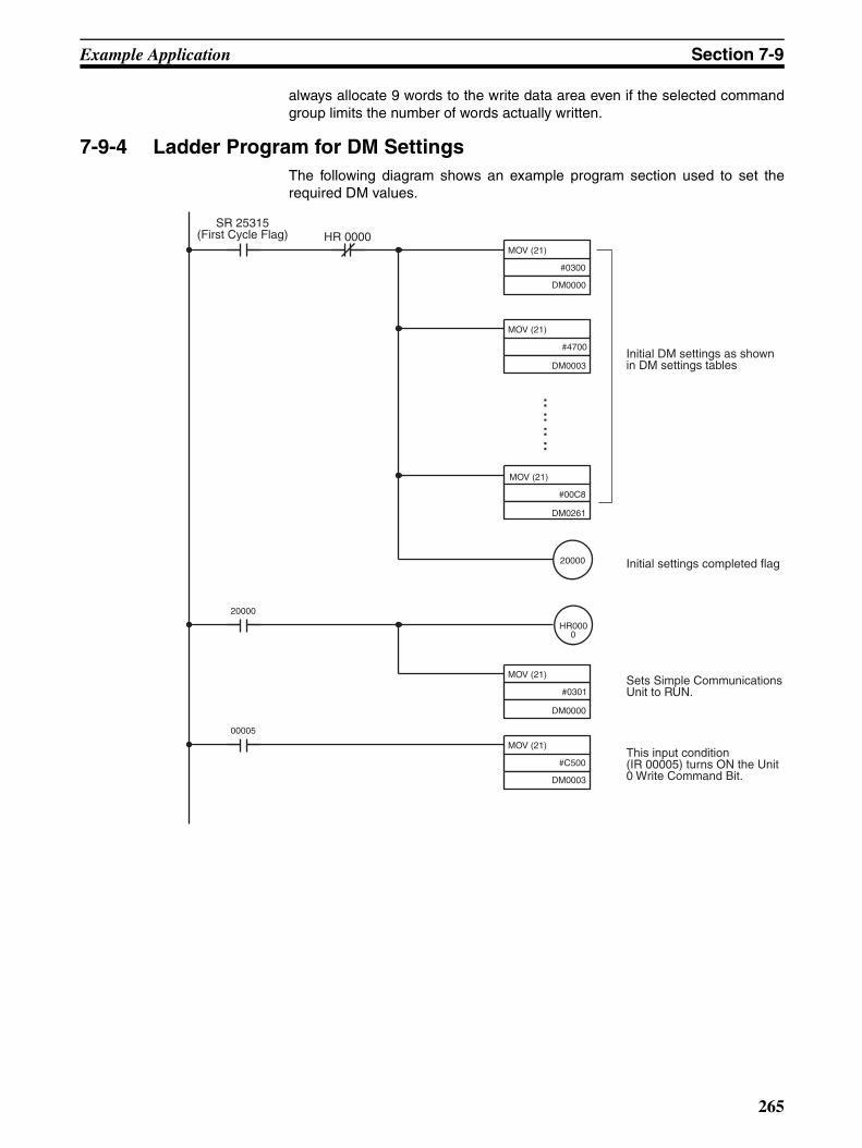
Example Application Section 7-9
always allocate 9 words to the write data area even if the selected commandgroup limits the number of words actually written.
7-9-4 Ladder Program for DM SettingsThe following diagram shows an example program section used to set therequired DM values.
SR 25315(First Cycle Flag) HR 0000
Initial DM settings as shown in DM settings tables
Initial settings completed flag
Sets Simple Communications Unit to RUN.
This input condition (IR 00005) turns ON the Unit 0 Write Command Bit.
MOV (21)
#0300
DM0000
MOV (21)
#4700
DM0003
MOV (21)
#00C8
DM0261
::::
20000
HR0000
MOV (21)
#0301
DM0000
MOV (21)
#C500
DM0003
20000
00005
265

Appendix AStandard Models
CPU UnitsClassification and
AppearanceI/O capacity Inputs Outputs Clock Model
Units with Terminal Blocks
10 I/O points 6 points (24 VDC)
4 relay outputs No CPM2C-10CDR-D
Yes CPM2C-10C1DR-D
20 I/O points 12 points (24 VDC)
8 relay outputs No CPM2C-20CDR-D
Yes CPM2C-20C1DR-D
Units with Fujitsu-compatible Connec-tors
10 I/O points 6 points (24 VDC)
4 transistor outputs (sinking) No CPM2C-10CDTC-D
Yes CPM2C-10C1DTC-D
4 transistor outputs (sourcing) No CPM2C-10CDT1C-D
Yes CPM2C-10C1DT1C-D
20 I/O points 12 points (24 VDC)
8 transistor outputs (sinking) No CPM2C-20CDTC-D
Yes CPM2C-20C1DTC-D
8 transistor outputs (sourcing) No CPM2C-20CDT1C-D
Yes CPM2C-20C1DT1C-D
32 I/O points 16 points (24 VDC)
16 transistor outputs (sinking) No CPM2C-32CDTC-D
16 transistor outputs (sourcing) No CPM2C-32CDT1C-D
Units with MIL Con-nectors
10 I/O points 6 points (24 VDC)
4 transistor outputs (sinking) No CPM2C-10CDTM-D
Yes CPM2C-10C1DTM-D
4 transistor outputs (sourcing) No CPM2C-10CDT1M-D
Yes CPM2C-10C1DT1M-D
20 I/O points 12 points (24 VDC)
8 transistor outputs (sinking) No CPM2C-20CDTM-D
Yes CPM2C-20C1DTM-D
8 transistor outputs (sourcing) No CPM2C-20CDT1M-D
Yes CPM2C-20C1DT1M-D
32 I/O points 16 points (24 VDC)
16 transistor outputs (sinking) No CPM2C-32CDTM-D
16 transistor outputs (sourcing) No CPM2C-32CDT1M-D
267

Standard Models Appendix A
Expansion I/O Units
I/O Connectors (OMRON Products)
Classification and Appearance
I/O capacity Inputs Outputs Model
Units with Terminal Blocks
10 I/O points 6 points (24 VDC) 4 relay outputs CPM2C-10EDR
20 I/O points 12 points (24 VDC) 8 relay outputs CPM2C-20EDR
8 output points --- 8 relay outputs CPM2C-8ER
Units with Fujitsu-compatible Connec-tors
24 I/O points 16 points (24 VDC) 8 transistor outputs (sinking) CPM2C-24EDTC
8 transistor outputs (sourcing) CPM2C-24EDT1C
32 I/O points 16 points (24 VDC) 16 transistor outputs (sinking) CPM2C-32EDTC
16 transistor outputs (sourcing) CPM2C-32EDT1C
8 input points 8 points (24 VDC) --- CPM2C-8EDC
16 input points 16 points (24 VDC) --- CPM2C-16EDC
8 output points --- 8 transistor outputs (sinking) CPM2C-8ETC
8 transistor outputs (sourcing) CPM2C-8ET1C
16 output points --- 16 transistor outputs (sinking) CPM2C-16ETC
16 transistor outputs (sourcing) CPM2C-16ET1C
Units with MIL Con-nectors
24 I/O points 16 points (24 VDC) 8 transistor outputs (sinking) CPM2C-24EDTM
8 transistor outputs (sourcing) CPM2C-24EDT1M
32 I/O points 16 points (24 VDC) 16 transistor outputs (sinking) CPM2C-32EDTM
16 transistor outputs (sourcing) CPM2C-32EDT1M
8 input points 8 points (24 VDC) --- CPM2C-8EDM
16 input points 16 points (24 VDC) --- CPM2C-16EDM
8 output points --- 8 transistor outputs (sinking) CPM2C-8ETM
8 transistor outputs (sourcing) CPM2C-8ET1M
16 outputs points
--- 16 transistor outputs (sinking) CPM2C-16ETM
16 transistor outputs (sourcing) CPM2C-16ET1M
Connector Description
C500-CE241 24-pin soldered connector with cover
C500-CE242 24-pin crimp connector with cover
C500-CE243 24-pin pressure connector
268

Standard Models Appendix A
Expansion Units
Analog I/O Unit
Temperature Sensor Units
CompoBus/S I/O Link Unit
Simple Communications Unit
AC Power Supply Unit
Communications Port Connecting Cables
Model Name Specifications
CPM2C-MAD11 Analog I/O Unit 2 analog inputs, 1 analog output
Model Name Specifications
CPM2C-TS001 Temperature Sensor Unit
2 thermocouple inputs
CPM2C-TS101 2 platinum resistance thermometer inputs
Model Name Specifications
CPM2C-SRT21 CompoBus/S I/O Link Unit
Allocates CPM2C I/O (8 inputs and 8 outputs) when CPM2C used as a CompoBus Slave.
Model Name Specifications
CPM2C-CIF21 Simple Communica-tions Unit
Up to 32 communications components supporting the CompoWay/F protocol and temperature control-lers and Digital Panel Meters supporting the SYSWAY protocol can be connected.
Model Name Specifications
CPM2C-PA201 AC Power Supply Unit
Input: 100 to 240 VACOutput: 24 VDC/600 mA
Connector Description Cable length
CPM2C-CN111 Connecting Cable
Converts the CPM2C CPU Unit’s communications port to a peripheral port and RS-232C port.
0.15 m (about 4”)
CS1W-CN114 Connecting Cable
Converts the CPM2C CPU Unit’s communications port to a peripheral port.
0.05 m (about 2”)
CS1W-CN118 Connecting Cable
Converts the CPM2C CPU Unit’s communications port to an RS-232C port.
0.1 m (about 2”)
269
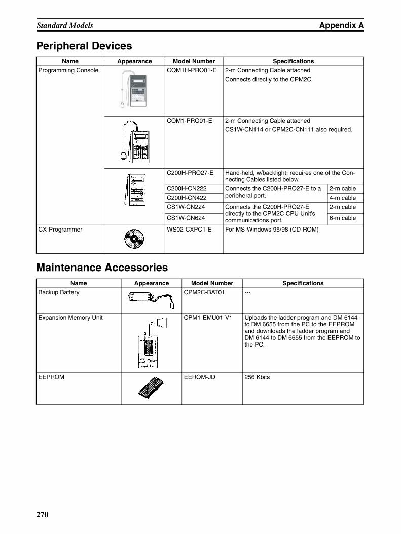
Standard Models Appendix A
Peripheral Devices
Maintenance Accessories
Name Appearance Model Number Specifications
Programming Console CQM1H-PRO01-E 2-m Connecting Cable attached
Connects directly to the CPM2C.
CQM1-PRO01-E 2-m Connecting Cable attached
CS1W-CN114 or CPM2C-CN111 also required.
C200H-PRO27-E Hand-held, w/backlight; requires one of the Con-necting Cables listed below.
C200H-CN222 Connects the C200H-PRO27-E to a peripheral port.
2-m cable
C200H-CN422 4-m cable
CS1W-CN224 Connects the C200H-PRO27-E directly to the CPM2C CPU Unit’s communications port.
2-m cable
CS1W-CN624 6-m cable
CX-Programmer WS02-CXPC1-E For MS-Windows 95/98 (CD-ROM)
Name Appearance Model Number Specifications
Backup Battery CPM2C-BAT01 ---
Expansion Memory Unit CPM1-EMU01-V1 Uploads the ladder program and DM 6144 to DM 6655 from the PC to the EEPROM and downloads the ladder program and DM 6144 to DM 6655 from the EEPROM to the PC.
EEPROM EEROM-JD 256 Kbits
270

Standard Models Appendix A
Adapters and Connecting Cables
Adapters (1:N Connections)
CPM2C com-munications port usage
Name Appearance Model number Comments Cable length
Personal Computer Con-necting Cable
CS1W-CN226 Use to connect a personal com-puter to the peripheral port.
D-sub, 9-pin
2 m
CS1W-CN626 6 m
Peripheral RS-232C Adapter
CQM1-CIF02 For a 9-pin computer serial port 3.3 m
Peripheral/RS-232C Adapter Unit
CPM2C-CIF01-V1
Use for peripheral port to RS-232C conversion.
---
RS-232C RS-232C Cable
XW2Z-200S For a 25-pin computer serial port 2 m
XW2Z-500S 5 m
XW2Z-200S-V For a 9-pin computer serial port 2 m
XW2Z-500S-V 5 m
RS-232C Cables(For use with the NT-AL001.)
XW2Z-070T-1 Use for CPM2C RS-232C port to NT-AL001 con-nection. (70-cm cable)
XW2Z-070T-1 Use for CPM2C RS-232C port to NT-AL001 con-nection. (2-m cable)
Name Appearance Model number Specifications
RS-422 Adapter NT-AL001 Use for CPM2C RS-232C port to RS-422A conversion. Requires a 5-VDC, 150 mA power supply which is supplied through the CPM2C connection.(Can also be connected to a personal computer, but this connection requires an external 5-VDC power supply.)
Link Adapter B500-AL004 Use for personal computer RS-232C port to RS-422A con-version.(Can also be connected to a CPM2C.)
RS-422/RS-232C Adapter Unit
CPM2C-CIF11 Use for CPM2C peripheral port to RS-422 conversion.
271

Appendix BDimensions
All dimensions are in millimeters.
CPU Units
(CPM2C-@0CDR-D, CPM2C-@0C1DR-D)(CPM2C-@@CDTC-D, CPM2C-@0C1DTC-D, CPM2C-@@CDT1C-D, CPM2C-@0C1DT1C-D)
CPU Units with Transistor Outputs and MIL Connectors(CPM2C-@@CDTM-D, CPM2C-@0C1DTM-D, CPM2C-@@CDT1M-D, CPM2C-@0C1DT1M-D)
33 65
90
CPU Units with Relay Outputs CPU Units with Transistor Outputs and Fujitsu-compatible Connectors
273
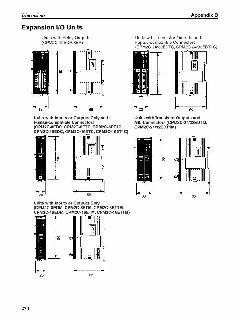
Dimensions Appendix B
Expansion I/O UnitsUnits with Relay Outputs(CPM2C-10EDR/8ER)
Units with Transistor Outputs and Fujitsu-compatible Connectors(CPM2C-24/32EDTC, CPM2C-24/32EDT1C)
Units with Inputs or Outputs Only andFujitsu-compatible Connectors(CPM2C-8EDC, CPM2C-8ETC, CPM2C-8ET1C, CPM2C-16EDC, CPM2C-16ETC, CPM2C-16ET1C)
20 65
90
Units with Transistor Outputs and MIL Connectors (CPM2C-24/32EDTM, CPM2C-24/32EDT1M)
Units with Inputs or Outputs Only(CPM2C-8EDM, CPM2C-8ETM, CPM2C-8ET1M, CPM2C-16EDM, CPM2C-16ETM, CPM2C-16ET1M)
90
33 65
90
20 65
274

Dimensions Appendix B
CPM2C-PA201 AC Power Supply Unit
Expansion Units
CPM2C-MAD11 Analog I/O Unit
CPM2C-TS001, CPM2C-TS101 Temperature Sensor Units
90
40
65
76.8
90
33 65
90
33 65
275

Dimensions Appendix B
CPM2C-SRT21 CompoBus/S I/O Link Unit
CPM2C-CIF21 Simple Communications Unit
Adapter Units
90
20 6590
33 65
CPM2C-CIF01-V1 Peripheral/RS-232C Adapter Unit
CPM2C-CIF11 RS-422/RS-232C Adapter Unit
90
33 65
90
33 65
276

Dimensions Appendix B
CPM2C Units with Connectors Attached
Units with Relay Outputs Units with Transistor Outputs(Using pressure connectors)
Units with Transistor Outputs(Using soldered connectors)
Units with Transistor Outputs and MIL Connectors
78
104
277

Dimensions Appendix B
WeightsUnit Model number Weight
CPU Units Terminal Blocks (Relay Out-puts)
10 I/O points
CPM2C-10CDR-D 200 g max.
CPM2C-10C1DR-D 200 g max.
20 I/O points
CPM2C-20CDR-D 250 g max.
CPM2C-20C1DR-D 250 g max.
Fujitsu- compatible Connectors
10 I/O points
CPM2C-10CDTC-D 200 g max.
CPM2C-10CD1DTC-D 200 g max.
CPM2C-10CDT1C-D 200 g max.
CPM2C-10C1DT1C-D 200 g max.
20 I/O points
CPM2C-20CDTC-D 200 g max.
CPM2C-20C1DTC-D 200 g max.
CPM2C-20CDT1C-D 200 g max.
CPM2C-20C1DT1C-D 200 g max.
32 I/O points
CPM2C-32CDTC-D 200 g max.
CPM2C-32CDT1C-D 200 g max.
MIL Connectors
10 I/O points
CPM2C-10CDTM-D 200 g max.
CPM2C-10C1DTM-D 200 g max.
CPM2C-10CDT1M-D 200 g max.
CPM2C-10C1DT1M-D 200 g max.
20 I/O points
CPM2C-20CDTM-D 200 g max.
CPM2C-20C1DTM-D 200 g max.
CPM2C-20CDT1M-D 200 g max.
CPM2C-20C1DT1M-D 200 g max.
32 I/O points
CPM2C-32CDTM-D 200 g max.
CPM2C-32CDT1M-D 200 g max.
278

Dimensions Appendix B
Expansion I/O Units
Terminal Blocks (Relay Out-puts)
10 I/O points
CPM2C-10EDR 200 g max.
20 I/O points
CPM2C-20EDR 200 g max.
8 output points
CPM2C-8ER 200 g max.
Fujitsu- compatible Connectors
24 I/O points
CPM2C-24EDTC 200 g max.
CPM2C-24EDT1C 200 g max.
32 I/O points
CPM2C-32EDTC 200 g max.
CPM2C-32EDT1C 200 g max.
8 input points
CPM2C-8EDC 150 g max.
16 input points
CPM2C-16EDC 150 g max.
8 output points
CPM2C-8ETC 150 g max.
CPM2C-8ET1C 150 g max.
16 output points
CPM2C-16ETC 150 g max.
CPM2C-16ET1C 150 g max.
MIL Connectors
24 I/O points
CPM2C-24EDTM 200 g max.
CPM2C-24EDT1M 200 g max.
32 I/O points
CPM2C-32EDTM 200 g max.
CPM2C-32EDT1M 200 g max.
8 input points
CPM2C-8EDM 150 g max.
16 input points
CPM2C-16EDM 150 g max.
8 output points
CPM2C-8ETM 150 g max.
CPM2C-8ET1M 150 g max.
16 output points
CPM2C-16ETM 150 g max.
CPM2C-16ET1M 150 g max.
Power Supply Unit CPM2C-PA201 250 g max.
Expansion I/O Units
Analog I/O Unit CPM2C-MAD11 200 g max.
Temperature Sensor Unit CPM2C-TS001 200 g max.
CPM2C-TS101 200 g max.
CompoBus/S I/O Link Unit CPM2C-SRT21 150 g max.
Simple Communications Unit
CPM2C-CIF21 150 g max.
Peripheral/RS-232C Adapter Unit CPM2C-CIF01-V1 150 g max.
RS-422/RS-232C Adapter Unit CPM2C-CIF11 150 g max.
Unit Model number Weight
279

Appendix CDM Settings Assignment Sheets
Control Data AreaDM _____ Contents Data
DM (+0) Simple Communications Unit control
DM (+1) Simple Communications Unit status*1
DM (+2) Syntax error DM address*1
DM (+3) Communications control for Units 0 to 7
DM (+4) Communications control for Units 8 to 15
DM (+5) Communications control for Units 16 to 23
DM (+6) Communications control for Units 24 to 31
DM (+7) Unit 0 communications type
DM (+8) Starting address of Unit 0 read data area (Starting address of Unit 0 read variable type area)
DM (+9) Starting address of Unit 0 write data area (Starting address of Unit 0 write variable type area)
DM (+10) Unit 1 communications type
DM (+11) Starting address of Unit 1 read data area (Starting address of Unit 1 read variable type area)
DM (+12) Starting address of Unit 1 write data area (Starting address of Unit 1 write variable type area)
DM (+13) Unit 2 communications type
DM (+14) Starting address of Unit 2 read data area (Starting address of Unit 2 read variable type area)
DM (+15) Starting address of Unit 2 write data area (Starting address of Unit 2 write variable type area)
DM (+16) Unit 3 communications type
DM (+17) Starting address of Unit 3 read data area (Starting address of Unit 3 read variable type area)
DM (+18) Starting address of Unit 3 write data area (Starting address of Unit 3 write variable type area)
DM (+19) Unit 4 communications type
DM (+20) Starting address of Unit 4 read data area (Starting address of Unit 4 read variable type area)
DM (+21) Starting address of Unit 4 write data area (Starting address of Unit 4 write variable type area)
DM (+22) Unit 5 communications type
DM (+23) Starting address of Unit 5 read data area (Starting address of Unit 5 read variable type area)
DM (+24) Starting address of Unit 5 write data area (Starting address of Unit 5 write variable type area)
DM (+25) Unit 6 communications type
DM (+26) Starting address of Unit 6 read data area (Starting address of Unit 6 read variable type area)
DM (+27) Starting address of Unit 6 write data area (Starting address of Unit 6 write variable type area)
DM (+28) Unit 7 communications type
DM (+29) Starting address of Unit 7 read data area (Starting address of Unit 7 read variable type area)
DM (+30) Starting address of Unit 7 write data area (Starting address of Unit 7 write variable type area)
DM (+31) Unit 8 communications type
DM (+32) Starting address of Unit 8 read data area (Starting address of Unit 8 read variable type area)
DM (+33) Starting address of Unit 8 write data area (Starting address of Unit 8 write variable type area)
DM (+34) Unit 9 communications type
DM (+35) Starting address of Unit 9 read data area (Starting address of Unit 9 read variable type area)
DM (+36) Starting address of Unit 9 write data area (Starting address of Unit 9 write variable type area)
DM (+37) Unit 10 communications type
DM (+38) Starting address of Unit 10 read data area (Starting address of Unit 10 read variable type area)
DM (+39) Starting address of Unit 10 write data area (Starting address of Unit 10 write variable type area)
DM (+40) Unit 11 communications type
DM (+41) Starting address of Unit 11 read data area (Starting address of Unit 11 read variable type area)
DM (+42) Starting address of Unit 11 write data area (Starting address of Unit 11 write variable type area)
DM (+43) Unit 12 communications type
DM (+44) Starting address of Unit 12 read data area (Starting address of Unit 12 read variable type area)
281
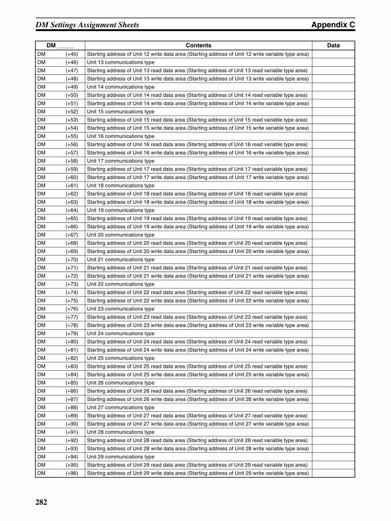
DM Settings Assignment Sheets Appendix C
DM (+45) Starting address of Unit 12 write data area (Starting address of Unit 12 write variable type area)
DM (+46) Unit 13 communications type
DM (+47) Starting address of Unit 13 read data area (Starting address of Unit 13 read variable type area)
DM (+48) Starting address of Unit 13 write data area (Starting address of Unit 13 write variable type area)
DM (+49) Unit 14 communications type
DM (+50) Starting address of Unit 14 read data area (Starting address of Unit 14 read variable type area)
DM (+51) Starting address of Unit 14 write data area (Starting address of Unit 14 write variable type area)
DM (+52) Unit 15 communications type
DM (+53) Starting address of Unit 15 read data area (Starting address of Unit 15 read variable type area)
DM (+54) Starting address of Unit 15 write data area (Starting address of Unit 15 write variable type area)
DM (+55) Unit 16 communications type
DM (+56) Starting address of Unit 16 read data area (Starting address of Unit 16 read variable type area)
DM (+57) Starting address of Unit 16 write data area (Starting address of Unit 16 write variable type area)
DM (+58) Unit 17 communications type
DM (+59) Starting address of Unit 17 read data area (Starting address of Unit 17 read variable type area)
DM (+60) Starting address of Unit 17 write data area (Starting address of Unit 17 write variable type area)
DM (+61) Unit 18 communications type
DM (+62) Starting address of Unit 18 read data area (Starting address of Unit 18 read variable type area)
DM (+63) Starting address of Unit 18 write data area (Starting address of Unit 18 write variable type area)
DM (+64) Unit 19 communications type
DM (+65) Starting address of Unit 19 read data area (Starting address of Unit 19 read variable type area)
DM (+66) Starting address of Unit 19 write data area (Starting address of Unit 19 write variable type area)
DM (+67) Unit 20 communications type
DM (+68) Starting address of Unit 20 read data area (Starting address of Unit 20 read variable type area)
DM (+69) Starting address of Unit 20 write data area (Starting address of Unit 20 write variable type area)
DM (+70) Unit 21 communications type
DM (+71) Starting address of Unit 21 read data area (Starting address of Unit 21 read variable type area)
DM (+72) Starting address of Unit 21 write data area (Starting address of Unit 21 write variable type area)
DM (+73) Unit 22 communications type
DM (+74) Starting address of Unit 22 read data area (Starting address of Unit 22 read variable type area)
DM (+75) Starting address of Unit 22 write data area (Starting address of Unit 22 write variable type area)
DM (+76) Unit 23 communications type
DM (+77) Starting address of Unit 23 read data area (Starting address of Unit 23 read variable type area)
DM (+78) Starting address of Unit 23 write data area (Starting address of Unit 23 write variable type area)
DM (+79) Unit 24 communications type
DM (+80) Starting address of Unit 24 read data area (Starting address of Unit 24 read variable type area)
DM (+81) Starting address of Unit 24 write data area (Starting address of Unit 24 write variable type area)
DM (+82) Unit 25 communications type
DM (+83) Starting address of Unit 25 read data area (Starting address of Unit 25 read variable type area)
DM (+84) Starting address of Unit 25 write data area (Starting address of Unit 25 write variable type area)
DM (+85) Unit 26 communications type
DM (+86) Starting address of Unit 26 read data area (Starting address of Unit 26 read variable type area)
DM (+87) Starting address of Unit 26 write data area (Starting address of Unit 26 write variable type area)
DM (+88) Unit 27 communications type
DM (+89) Starting address of Unit 27 read data area (Starting address of Unit 27 read variable type area)
DM (+90) Starting address of Unit 27 write data area (Starting address of Unit 27 write variable type area)
DM (+91) Unit 28 communications type
DM (+92) Starting address of Unit 28 read data area (Starting address of Unit 28 read variable type area)
DM (+93) Starting address of Unit 28 write data area (Starting address of Unit 28 write variable type area)
DM (+94) Unit 29 communications type
DM (+95) Starting address of Unit 29 read data area (Starting address of Unit 29 read variable type area)
DM (+96) Starting address of Unit 29 write data area (Starting address of Unit 29 write variable type area)
DM _____ Contents Data
282
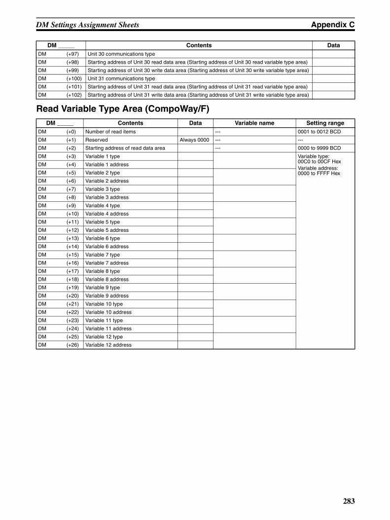
DM Settings Assignment Sheets Appendix C
Read Variable Type Area (CompoWay/F)
DM (+97) Unit 30 communications type
DM (+98) Starting address of Unit 30 read data area (Starting address of Unit 30 read variable type area)
DM (+99) Starting address of Unit 30 write data area (Starting address of Unit 30 write variable type area)
DM (+100) Unit 31 communications type
DM (+101) Starting address of Unit 31 read data area (Starting address of Unit 31 read variable type area)
DM (+102) Starting address of Unit 31 write data area (Starting address of Unit 31 write variable type area)
DM _____ Contents Data Variable name Setting rangeDM (+0) Number of read items --- 0001 to 0012 BCD
DM (+1) Reserved Always 0000 --- ---
DM (+2) Starting address of read data area --- 0000 to 9999 BCD
DM (+3) Variable 1 type Variable type:00C0 to 00CF HexVariable address:0000 to FFFF Hex
DM (+4) Variable 1 address
DM (+5) Variable 2 type
DM (+6) Variable 2 address
DM (+7) Variable 3 type
DM (+8) Variable 3 address
DM (+9) Variable 4 type
DM (+10) Variable 4 address
DM (+11) Variable 5 type
DM (+12) Variable 5 address
DM (+13) Variable 6 type
DM (+14) Variable 6 address
DM (+15) Variable 7 type
DM (+16) Variable 7 address
DM (+17) Variable 8 type
DM (+18) Variable 8 address
DM (+19) Variable 9 type
DM (+20) Variable 9 address
DM (+21) Variable 10 type
DM (+22) Variable 10 address
DM (+23) Variable 11 type
DM (+24) Variable 11 address
DM (+25) Variable 12 type
DM (+26) Variable 12 address
DM _____ Contents Data
283

DM Settings Assignment Sheets Appendix C
Write Variable Type Area (CompoWay/F)DM _____ Contents Data Variable name Setting range
DM (+0) Number of write items --- 0000 to 0012 BCD
DM (+1) Operation Command --- 0000: None0001: Command set
DM (+2) Starting address of write data area --- 0000 to 9999 BCD
DM (+3) Variable 1 type Variable type:00C0 to 00CF HexVariable address:0000 to FFFF Hex
DM (+4) Variable 1 address
DM (+5) Variable 2 type
DM (+6) Variable 2 address
DM (+7) Variable 3 type
DM (+8) Variable 3 address
DM (+9) Variable 4 type
DM (+10) Variable 4 address
DM (+11) Variable 5 type
DM (+12) Variable 5 address
DM (+13) Variable 6 type
DM (+14) Variable 6 address
DM (+15) Variable 7 type
DM (+16) Variable 7 address
DM (+17) Variable 8 type
DM (+18) Variable 8 address
DM (+19) Variable 9 type
DM (+20) Variable 9 address
DM (+21) Variable 10 type
DM (+22) Variable 10 address
DM (+23) Variable 11 type
DM (+24) Variable 11 address
DM (+25) Variable 12 type
DM (+26) Variable 12 address
284
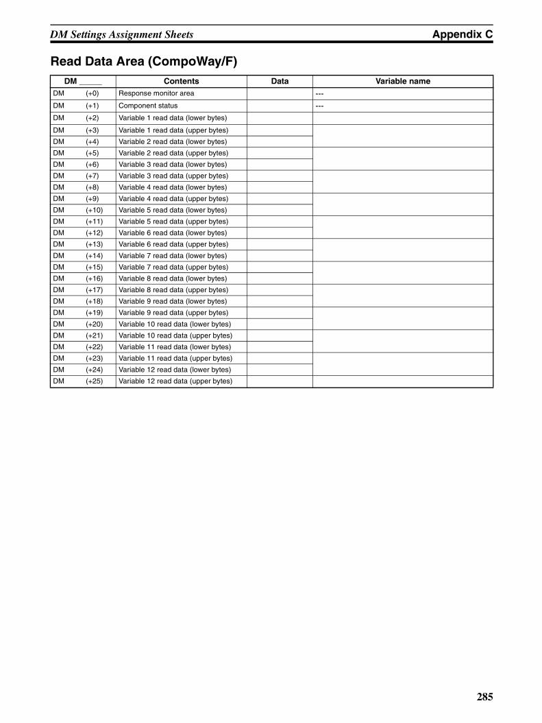
DM Settings Assignment Sheets Appendix C
Read Data Area (CompoWay/F)DM _____ Contents Data Variable name
DM (+0) Response monitor area ---DM (+1) Component status ---DM (+2) Variable 1 read data (lower bytes)
DM (+3) Variable 1 read data (upper bytes)
DM (+4) Variable 2 read data (lower bytes)
DM (+5) Variable 2 read data (upper bytes)
DM (+6) Variable 3 read data (lower bytes)
DM (+7) Variable 3 read data (upper bytes)
DM (+8) Variable 4 read data (lower bytes)
DM (+9) Variable 4 read data (upper bytes)
DM (+10) Variable 5 read data (lower bytes)
DM (+11) Variable 5 read data (upper bytes)
DM (+12) Variable 6 read data (lower bytes)
DM (+13) Variable 6 read data (upper bytes)
DM (+14) Variable 7 read data (lower bytes)
DM (+15) Variable 7 read data (upper bytes)
DM (+16) Variable 8 read data (lower bytes)
DM (+17) Variable 8 read data (upper bytes)
DM (+18) Variable 9 read data (lower bytes)
DM (+19) Variable 9 read data (upper bytes)
DM (+20) Variable 10 read data (lower bytes)
DM (+21) Variable 10 read data (upper bytes)
DM (+22) Variable 11 read data (lower bytes)
DM (+23) Variable 11 read data (upper bytes)
DM (+24) Variable 12 read data (lower bytes)
DM (+25) Variable 12 read data (upper bytes)
285

DM Settings Assignment Sheets Appendix C
Write Data Area (CompoWay/F)DM _____ Contents Data Variable name
DM (+0) Response monitor area ---
DM (+1) Operation Command ---
DM (+2) Variable 1 write data (lower bytes)
DM (+3) Variable 1 write data (upper bytes)
DM (+4) Variable 2 write data (lower bytes)
DM (+5) Variable 2 write data (upper bytes)
DM (+6) Variable 3 write data (lower bytes)
DM (+7) Variable 3 write data (upper bytes)
DM (+8) Variable 4 write data (lower bytes)
DM (+9) Variable 4 write data (upper bytes)
DM (+10) Variable 5 write data (lower bytes)
DM (+11) Variable 5 write data (upper bytes)
DM (+12) Variable 6 write data (lower bytes)
DM (+13) Variable 6 write data (upper bytes)
DM (+14) Variable 7 write data (lower bytes)
DM (+15) Variable 7 write data (upper bytes)
DM (+16) Variable 8 write data (lower bytes)
DM (+17) Variable 8 write data (upper bytes)
DM (+18) Variable 9 write data (lower bytes)
DM (+19) Variable 9 write data (upper bytes)
DM (+20) Variable 10 write data (lower bytes)
DM (+21) Variable 10 write data (upper bytes)
DM (+22) Variable 11 write data (lower bytes)
DM (+23) Variable 11 write data (upper bytes)
DM (+24) Variable 12 write data (lower bytes)
DM (+25) Variable 12 write data (upper bytes)
286

DM Settings Assignment Sheets Appendix C
Read Data Area (SYSWAY: Temperature Controllers)
Read Data Area (SYSWAY: Digital Panel Meters)
DM _____ Contents Data Command group
1 2 3 4 5DM (+0) Response monitor area Read Read Read Read Read
DM (+1) Present temperature Read Read Read Read Read
DM (+2) Status Read Read Read Read Read
DM (+3) Target temperature Read Read Read Read Read
DM (+4) Alarm 1 SV --- --- Read Read Read
DM (+5) Alarm 2 SV --- --- Read Read Read
DM (+6) Proportional band --- --- --- Read Read
DM (+7) Reset time --- --- --- Read Read
DM (+8) Derivative time --- --- --- Read Read
DM (+9) Heater current monitor --- --- --- --- Read
DM (+10) Heater current status --- --- --- --- Read
DM _____ Contents Data Command group
1 2 3 4 5DM (+0) Response monitor area Read Read Read Read Read
DM (+1) Display value (Lower bytes) Read Read Read Read Read
DM (+2) Display value (Upper bytes) Read Read Read Read Read
DM (+3) Display value status Read Read Read --- Read
DM (+4) Peak hold (Lower bytes) --- Read Read --- Read
DM (+5) Peak hold (Upper bytes) --- Read Read --- Read
DM (+6) Peak hold status --- Read Read --- Read
DM (+7) Bottom hold (Lower bytes) --- Read Read --- Read
DM (+8) Bottom hold (Upper bytes) --- Read Read --- Read
DM (+9) Bottom hold status --- Read Read --- Read
DM (+10) Comparison value HH (Lower bytes) --- --- --- Read Read
DM (+11) Comparison value HH (Upper bytes) --- --- --- Read Read
DM (+12) Comparison value H (Lower bytes) --- --- --- Read Read
DM (+13) Comparison value H (Upper bytes) --- --- --- Read Read
DM (+14) Comparison value L (Lower bytes) --- --- --- Read Read
DM (+15) Comparison value L (Upper bytes) --- --- --- Read Read
DM (+16) Comparison value LL (Lower bytes) --- --- --- Read Read
DM (+17) Comparison value LL (Upper bytes) --- --- --- Read Read
287

DM Settings Assignment Sheets Appendix C
Write Data Area (SYSWAY: Temperature Controllers)
Write Data Area (SYSWAY: Digital Panel Meters)
DM _____ Contents Data Command group
1 2 3 4 5DM (+0) Response monitor area Written Written Written Written Written
DM (+1) Target temperature SV Written Written Written Written Written
DM (+2) Operation Command --- Written Written Written Written
DM (+3) Alarm 1 SV --- --- Written Written Written
DM (+4) Alarm 2 SV --- --- Written Written Written
DM (+5) Proportional band --- --- --- Written Written
DM (+6) Reset time --- --- --- Written Written
DM (+7) Derivative time --- --- --- Written Written
DM (+8) Heater burnout detection value --- --- --- --- Written
DM _____ Contents Data Command group
1 2 3 4 5DM (+0) Response monitor area Written Written Written Written Written
DM (+1) Operation Command --- --- Written --- Written
DM (+2) Comparison value HH (Lower bytes) --- --- --- Written Written
DM (+3) Comparison value HH (Upper bytes) --- --- ---
DM (+4) Comparison value H (Lower bytes) --- --- --- Written Written
DM (+5) Comparison value H (Upper bytes) --- --- ---
DM (+6) Comparison value L (Lower bytes) --- --- --- Written Written
DM (+7) Comparison value L (Upper bytes) --- --- ---
DM (+8) Comparison value LL (Lower bytes) --- --- --- Written Written
DM (+9) Comparison value LL (Upper bytes) --- --- ---
288

Appendix DSYSMAC and SYSMAC-CPT Support
Software
SYSMAC-CPT Support Software
IntroductionThe SYSMAC-CPT Support Software is a complete programming and control package. It provides not onlyprogramming capabilities, but also advanced debugging, monitoring, and program/data management. The soft-ware is compatible with Windows 3.1, Windows 95, and Windows 98.
Any version of the SYSMAC-CPT Support Software can be used to program CPM2C PCs with the limitationsdescribed later in this section. For further information and actual operating procedures, please refer to theSYSMAC-CPT Support Software Quick Start Guide (W332) and User Manual (W333).
Refer to 3-4-10 Programming Device Connections for details on connecting a personal computer to theCPM2C.
Limitations and PrecautionsWhen programming a CPM2C PC with the SYSMAC-CPT Support Software, set the PC model to “CQM1” andthe CPU model to “CPU43.” There are some software limitations because of differences between the CPM2Cand CQM1-CPU43 CPUs.
Program Input and Program CheckCQM1 data areas are larger than the corresponding CPM2C data areas, so the data area addresses that don’tactually exist in the CPM2C or instructions not supported by the CPM2C can be input and won’t be detected inthe program check. Be sure that the word and bit addresses are within the specified ranges and that all instruc-tions are supported.
If a program contains a data area address that exceeds the range of a CPM2C data area, a memory error willbe generated when the program is executed and the Memory Area Specification Error Flag (AR 1308) will beturned ON.
Data area CQM1 range CPM2C range
Input words IR 000 to IR 011 IR 000 to IR 009
Output words IR 100 to IR 111 IR 010 to IR 019
Work words and dedicated words
IR 012 to IR 099IR 112 to IR 227
IR 020 to IR 049/IR 200 to IR 227(IR 050 to IR 199 cannot be used.)
SR area SR 228 to SR 255 SR 228 to SR 255
HR area HR 00 to HR 99 HR 00 to HR 19(HR 20 to HR 99 cannot be used.)
AR area AR 00 to AR 27 AR 00 to AR 23(AR 24 to AR 27 cannot be used.)
LR area LR 00 to LR 63 LR 00 to LR 15(LR 16 to LR 63 cannot be used.)
Timer/Counter area
TIM/CNT 000 to 511 TIM/CNT 000 to 255(TIM/CNT 256 to 511 cannot be used.)
DM area
Read/write DM 0000 to DM 6143 DM 0000 to DM 1999,DM 2022 to DM 2047(DM 2048 to DM 6143 cannot be used.)
Read-only DM 6144 to DM 6568 DM 6144 to DM 6599
Error Log DM 6569 to DM 6599 DM 2000 to DM 2021
PC Setup DM 6600 to DM 6655 DM 6600 to DM 6655
289

SYSMAC and SYSMAC-CPT Support Software Appendix D
Since the PC model is set to “CQM1,” a program that will run properly in the CQM1 will pass the program checkeven if it won’t run properly in the CPM2C.
Monitoring, Online Editing, and Set ValuesAn error message will be displayed and the values will not be accepted if a data area address that exceeds therange of a CPM2C data area is entered for monitoring, an instruction operand, or a timer/counter SV.
Available Program MemoryThe program capacity of the CQM1 (7,200 words) is greater than that of the CPM2C (4,096 words), and so thedisplay will show more free space than is actually available. Be sure to keep the actual program capacity inmind while programming.
Program TransferWhen the program is transferred from the PC to the CPT with the default function code assignments, FUN18,FUN19, FUN87, and FUN88 will be displayed as TKY, MCMP, DSW, and 7SEG. The instructions, however, willbe transferred correctly.
An error will occur if any instructions not supported by the CPT are transferred from the CPM2C.
When the program is transferred from the CPT to the PC, TKY, MCMP, DSW, and 7SEG will be displayed onthe CPT, but will not be executed in the CPU Unit. They will be treated as NOP(00).
If expansion instructions are transferred to the PC with DM 6602 is set to the “default settings” or if instructionsnot supported by the CPM2C are transferred to the PC, a message saying that expansion instructions cannotbe written because DIP switch pin 4 is OFF will be displayed. Change the setting of DM 6602 to enable usersettings to use expansion instructions.
Expansion InstructionsIt will not be possible to transfer the program if the function codes assigned to expansion instructions (18instructions) have been changed from their default settings. A message to turn ON the DIP switch of the PCand execute again will be displayed. Change the function code assignments to the CQM1 defaults shown in thefollowing table before programming.
There are four CPM2C instructions (STUP(−−), SYNC(−−), TIML(−−), and TMHH(−−)) that are not supportedby the CQM1 and cannot be used. If one of these instructions is used in the program, an error will occur whenthe program is transferred from the PC to the computer.
The input word for the frequency for PWM must be between IR 000 and IR 049, or between IR 200 and IR 252.
Function code Default CPM2C Assignments Default CQM1 Assignments
17 ASFT ASFT
18 --- TKY
19 --- MCMP
47 RXD RXD
48 TXD TXD
60 CMPL CMPL
61 INI INI
62 PRV PRV
63 CTBL CTBL
64 SPED SPED
65 PULS PULS
66 SCL SCL
67 BCNT BCNT
68 BCMP BCMP
69 STIM STIM
87 --- DSW
88 --- 7SEG
89 INT INT
290
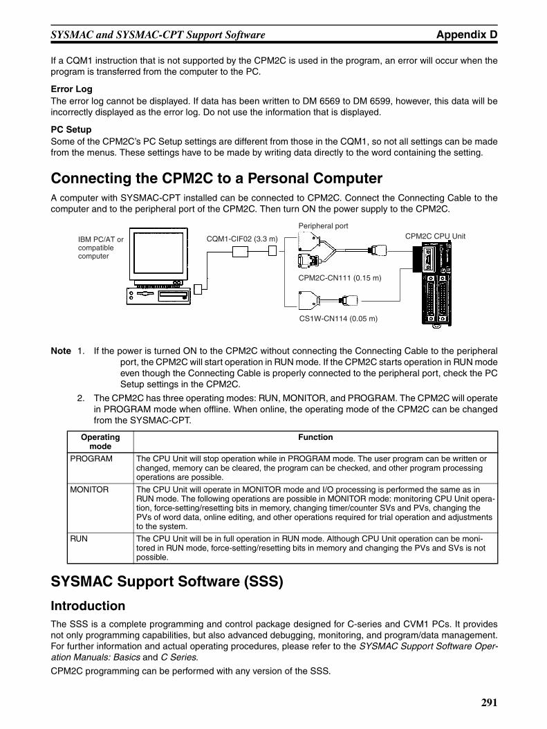
SYSMAC and SYSMAC-CPT Support Software Appendix D
If a CQM1 instruction that is not supported by the CPM2C is used in the program, an error will occur when theprogram is transferred from the computer to the PC.
Error LogThe error log cannot be displayed. If data has been written to DM 6569 to DM 6599, however, this data will beincorrectly displayed as the error log. Do not use the information that is displayed.
PC SetupSome of the CPM2C’s PC Setup settings are different from those in the CQM1, so not all settings can be madefrom the menus. These settings have to be made by writing data directly to the word containing the setting.
Connecting the CPM2C to a Personal ComputerA computer with SYSMAC-CPT installed can be connected to CPM2C. Connect the Connecting Cable to thecomputer and to the peripheral port of the CPM2C. Then turn ON the power supply to the CPM2C.
Note 1. If the power is turned ON to the CPM2C without connecting the Connecting Cable to the peripheralport, the CPM2C will start operation in RUN mode. If the CPM2C starts operation in RUN modeeven though the Connecting Cable is properly connected to the peripheral port, check the PCSetup settings in the CPM2C.
2. The CPM2C has three operating modes: RUN, MONITOR, and PROGRAM. The CPM2C will operatein PROGRAM mode when offline. When online, the operating mode of the CPM2C can be changedfrom the SYSMAC-CPT.
SYSMAC Support Software (SSS)
IntroductionThe SSS is a complete programming and control package designed for C-series and CVM1 PCs. It providesnot only programming capabilities, but also advanced debugging, monitoring, and program/data management.For further information and actual operating procedures, please refer to the SYSMAC Support Software Oper-ation Manuals: Basics and C Series.
CPM2C programming can be performed with any version of the SSS.
Peripheral portCPM2C CPU Unit
CPM2C-CN111 (0.15 m)
CS1W-CN114 (0.05 m)
CQM1-CIF02 (3.3 m)IBM PC/AT or compatible computer
Operating mode
Function
PROGRAM The CPU Unit will stop operation while in PROGRAM mode. The user program can be written or changed, memory can be cleared, the program can be checked, and other program processing operations are possible.
MONITOR The CPU Unit will operate in MONITOR mode and I/O processing is performed the same as in RUN mode. The following operations are possible in MONITOR mode: monitoring CPU Unit opera-tion, force-setting/resetting bits in memory, changing timer/counter SVs and PVs, changing the PVs of word data, online editing, and other operations required for trial operation and adjustments to the system.
RUN The CPU Unit will be in full operation in RUN mode. Although CPU Unit operation can be moni-tored in RUN mode, force-setting/resetting bits in memory and changing the PVs and SVs is not possible.
291
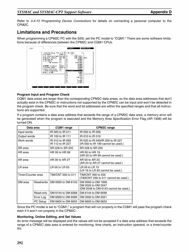
SYSMAC and SYSMAC-CPT Support Software Appendix D
Refer to 3-4-10 Programming Device Connections for details on connecting a personal computer to theCPM2C.
Limitations and PrecautionsWhen programming a CPM2C PC with the SSS, set the PC model to “CQM1.” There are some software limita-tions because of differences between the CPM2C and CQM1 CPUs.
Program Input and Program CheckCQM1 data areas are larger than the corresponding CPM2C data areas, so the data area addresses that don’tactually exist in the CPM2C or instructions not supported by the CPM2C can be input and won’t be detected inthe program check. Be sure that the word and bit addresses are within the specified ranges and that all instruc-tions are supported.
If a program contains a data area address that exceeds the range of a CPM2C data area, a memory error willbe generated when the program is executed and the Memory Area Specification Error Flag (AR 1308) will beturned ON.
Since the PC model is set to “CQM1,” a program that will run properly in the CQM1 will pass the program checkeven if it won’t run properly in the CPM2C.
Monitoring, Online Editing, and Set ValuesAn error message will be displayed and the values will not be accepted if a data area address that exceeds therange of a CPM2C data area is entered for monitoring, time charts, an instruction operand, or a timer/counterSV.
CQM1
A: CVM1-CPU21
K: CQM1
Data area CQM1 range CPM2C range
Input words IR 000 to IR 011 IR 000 to IR 009
Output words IR 100 to IR 111 IR 010 to IR 019
Work words IR 012 to IR 099IR 112 to IR 227
IR 020 to IR 049/IR 200 to IR 227(IR 050 to IR 199 cannot be used.)
SR area SR 228 to SR 255 SR 228 to SR 255
HR area HR 00 to HR 99 HR 00 to HR 19(HR 20 to HR 99 cannot be used.)
AR area AR 00 to AR 27 AR 00 to AR 23(AR 24 to AR 27 cannot be used.)
LR area LR 00 to LR 63 LR 00 to LR 15(LR 16 to LR 63 cannot be used.)
Timer/Counter area TIM/CNT 000 to 511 TIM/CNT 000 to 255(TIM/CNT 256 to 511 cannot be used.)
DM area Read/write DM 0000 to DM 6143 DM 0000 to DM 1999,DM 2022 to DM 2047(DM 2048 to DM 6143 cannot be used.)
Read-only DM 6144 to DM 6568 DM 6144 to DM 6599
Error Log DM 6569 to DM 6599 DM 2000 to DM 2021
PC Setup DM 6600 to DM 6655 DM 6600 to DM 6655
292
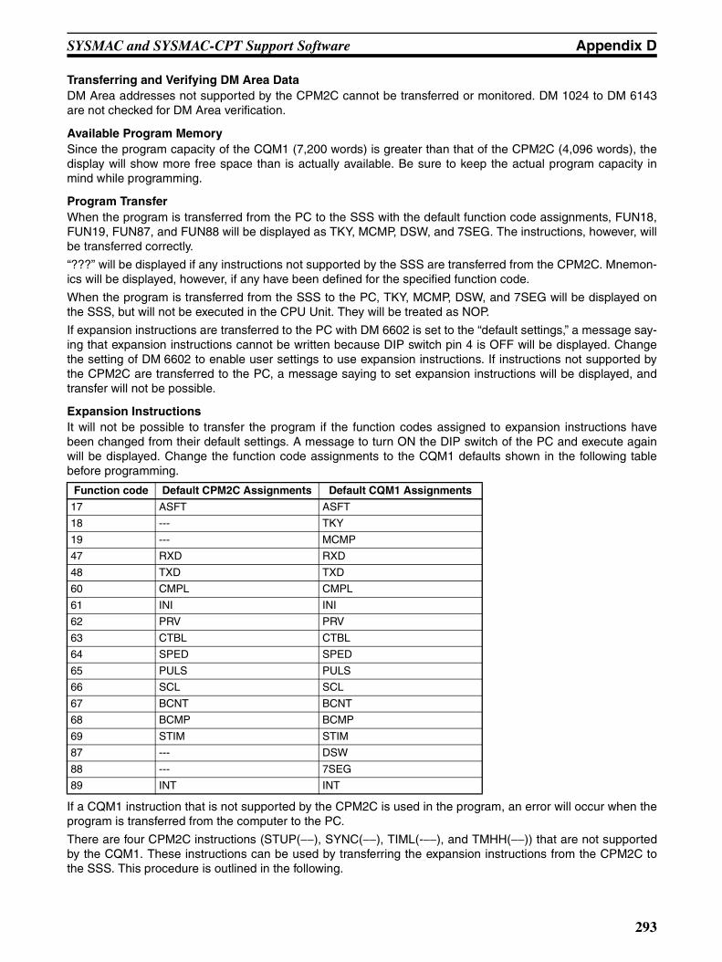
SYSMAC and SYSMAC-CPT Support Software Appendix D
Transferring and Verifying DM Area DataDM Area addresses not supported by the CPM2C cannot be transferred or monitored. DM 1024 to DM 6143are not checked for DM Area verification.
Available Program MemorySince the program capacity of the CQM1 (7,200 words) is greater than that of the CPM2C (4,096 words), thedisplay will show more free space than is actually available. Be sure to keep the actual program capacity inmind while programming.
Program TransferWhen the program is transferred from the PC to the SSS with the default function code assignments, FUN18,FUN19, FUN87, and FUN88 will be displayed as TKY, MCMP, DSW, and 7SEG. The instructions, however, willbe transferred correctly.
“???” will be displayed if any instructions not supported by the SSS are transferred from the CPM2C. Mnemon-ics will be displayed, however, if any have been defined for the specified function code.
When the program is transferred from the SSS to the PC, TKY, MCMP, DSW, and 7SEG will be displayed onthe SSS, but will not be executed in the CPU Unit. They will be treated as NOP.
If expansion instructions are transferred to the PC with DM 6602 is set to the “default settings,” a message say-ing that expansion instructions cannot be written because DIP switch pin 4 is OFF will be displayed. Changethe setting of DM 6602 to enable user settings to use expansion instructions. If instructions not supported bythe CPM2C are transferred to the PC, a message saying to set expansion instructions will be displayed, andtransfer will not be possible.
Expansion InstructionsIt will not be possible to transfer the program if the function codes assigned to expansion instructions havebeen changed from their default settings. A message to turn ON the DIP switch of the PC and execute againwill be displayed. Change the function code assignments to the CQM1 defaults shown in the following tablebefore programming.
If a CQM1 instruction that is not supported by the CPM2C is used in the program, an error will occur when theprogram is transferred from the computer to the PC.
There are four CPM2C instructions (STUP(−−), SYNC(−−), TIML(-−−), and TMHH(−−)) that are not supportedby the CQM1. These instructions can be used by transferring the expansion instructions from the CPM2C tothe SSS. This procedure is outlined in the following.
Function code Default CPM2C Assignments Default CQM1 Assignments
17 ASFT ASFT
18 --- TKY
19 --- MCMP
47 RXD RXD
48 TXD TXD
60 CMPL CMPL
61 INI INI
62 PRV PRV
63 CTBL CTBL
64 SPED SPED
65 PULS PULS
66 SCL SCL
67 BCNT BCNT
68 BCMP BCMP
69 STIM STIM
87 --- DSW
88 --- 7SEG
89 INT INT
293

SYSMAC and SYSMAC-CPT Support Software Appendix D
1. Select “Transfer Instr” from the “Utility” menu.
2. Confirm the transfer by pressing “Y” when the confirmation pop-up is displayed.
3. The “Utility” menu will be displayed again when the transfer is completed.
PC SetupSince some of the CPM2C’s PC Setup settings are different from those in the CQM1, not all settings can bemade from the menus. These settings have to be made by writing data directly to the word containing the set-ting.
294

Index
Numerics1:1 connections, 148
1:N connections, 145
AAC Power Supply Unit
See also Power Supply Unit
Adapter Units
available models, 13, 271
components, 77
dimensions, 276
Adapters
available models, 271
Analog I/O Unit
available models, 269
components, 69
dimensions, 275
See also Expansion Units
arc killer
examples, xxii
ASCII
converting displays
Programming Console, 183
atmosphere, 36
Bbasic functions, 24
battery
replacing, 209
binary data
modifying
Programming Console, 179
bit status
force-set/reset
Programming Console, 181
bits
searching
Programming Console, 169
buzzer operation
Programming Console, 163
Ccabinet
installation
precautions, 85
Programming Console installation, 154
cables
available models, 269
characteristics, 36
check levels
program checks, 198
checking
program syntax
Programming Console, 171
circuit configuration
inputs, 39
outputs
relay, 42
transistor, 44
clearing
memory areas
Programming Console, 161
clock
reading and setting the clock, 184
communications
capabilities, 24
overview, 5errors, 198
CompoBus/S I/O Link, 149
CompoBus/S I/O Link Unit
available models, 269
components, 72
dimensions, 276
See also Expansion Units
components
Adapter Units, 77
Analog I/O Unit, 69
CompoBus/S I/O Link Unit, 72
CPU Units, 47
Expansion I/O Units, 59
Power Supply Unit, 82
Temperature Sensor Units, 70
conduit installation, 90
connectors
available models, 268
dimensions, 277
counters
changing SV
Programming Console, 177
example of inputting, 188
CPM1A
function comparison, 24
CPM2A
295
Index
function comparison, 24
CPU Units
available models, 9, 267
components, 47
cyclic operation, 18
dimensions, 273
general specifications, 36
input specifications, 38
internal structure, 14
cycle time
displaying
Programming Console, 183
cyclic operation, 18
Ddata
modifying
Programming Console, 177–181
data link, 6, 148
decimal data with sign
See also signed decimal data
decimal data without sign
See also unsigned decimal data
dielectric strength, 36
differentiated instructions
entering, 167
dimensions, 273
DIN Track installation, 88
displays
converting between hex and ASCII
Programming Console, 183
cycle time
Programming Console, 183
downloading
programs, 218
duct installation, 89
EEC Directives
precautions, xxi
EEPROM
mounting/removing, 214
specifications, 213
electrical noise
preventing, 86, 89
ERR/ALM indicator
flashing, 197
lit, 197
errors
communications, 198
error processing, 193
fatal, 197
identifying, 195
non-fatal, 196
programming, 198
Programming Console operations, 198
reading/clearing messages
Programming Console, 163
user-defined errors, 196
Expansion I/O Units
available models, 11, 268
components, 59
connections, 87
dimensions, 274
general specifications, 36
input specifications, 41
expansion instructions, 293
reading and changing function code assignments, 164
Expansion Memory Unit, 211
connections, 215
Expansion Units
available models, 13, 269
components, 69
connections, 87
dimensions, 275
specifications, 36
FFAL numbers, 196
FAL(06), 196
FALS numbers, 197
FALS(07), 196
false inputs, 115
fatal errors
troubleshooting, 202
features, 2flash memory
precautions, 194
flicker output
example, 189
force-set/reset
clearing
Programming Console, 182
Programming Console, 181
296

Index
function codes
reading and changing expansion instruction assignments,164
functions, 7comparison, 24
hexadecimal data
converting displays
Programming Console, 183
H–Ihumidity, 36
I/O capacity, 37
I/O connectors
available models, 268
pin allocation
CPU Units, 51
Expansion I/O Units, 61
wiring, 94
I/O errors
troubleshooting, 204
I/O line noise
preventing, 89
I/O refreshing
immediate refreshing, 21
I/O terminals
allocation
CPU Units, 51
Expansion I/O Units, 61
immediate refreshing, 21
indicators
CompoBus/S LED indicators, 72
flashing ERR/ALM indicator, 197
lit ERR/ALM indicator, 197
PC status indicators, 48
inductive loads, 116, 140
initialization
time required, 16
input devices
connections, 113
input specifications
CPU Units, 38
Expansion I/O Units, 41
inputs
wiring, 101
configuration, 101
inrush current, 36
suppressing, 140
inspections, 208
installation, 88
site
selecting, 85
instructions
inserting and deleting
Programming Console, 170
searching
Programming Console, 168
insulation resistance, 36
interlocks, 84
interrupt program execution
in cyclic operation, 20
leakage current, 115
LED indicators, 48
limit switches
preventing false inputs, 115
L–Mmachine control functions
list, 22
maintenance, 208
accessories, 270
functions, 24
memory
backup, 38
Expansion Memory Unit, 211
protection, 38
memory areas
clearing
Programming Console, 161
partial clear, 161
uploading/downloading, 212
messages
reading/clearing, 163
model numbers, 267
modes
changing the PC mode, 157
operating modes, 15
modifying
binary data
Programming Console, 179
data
Programming Console, 177
hexadecimal/BCD data
Programming Console, 178
signed decimal data
Programming Console, 180
SV
297

Index
Programming Console, 177
unsigned decimal data
Programming Console, 181
MONITOR mode
description, 157
example test run, 190
monitoring
3-word monitor
Programming Console, 175–176
binary monitor
Programming Console, 174–175
differentiation monitor
Programming Console, 174
signed decimal monitor
Programming Console, 176
status
Programming Console, 172
unsigned decimal monitor
Programming Console, 176–177
motor control
capabilities, 3MSG(46), 196
Nnoise
immunity, 36
preventing electrical noise, 86, 89
non-fatal errors
troubleshooting, 203
no-protocol communications, 146
NPN current output
connections, 113
NPN open collector
connections, 113
NT Link
connections, 147
Ooperating conditions
troubleshooting, 206
operating modes, 15
operating mode at startup, 15
operation
preparations, 158
output short protection, 139
output specifications
relay output, 42
transistor output, 44
output wiring
configuration, 116
relay output, 116
transistor output
sinking, 120–121, 123–125
sourcing, 120–125
Ppanel
installation
precautions, 85
Programming Console installation, 154
password
entering on Programming Console, 159
PC mode
changing, 157
PC status
indicators, 48
Peripheral Devices
available models, 270
photoelectric switches
preventing false inputs, 115
platinum resistance thermometer, 4PNP current output
connections, 113
position control, 3power
consumption, 36
power cables, 89
power interruption
detection, 16
power supply
interrupt time, 36
precautions, 84
troubleshooting, 201, 207
wiring, 90
Power Supply Unit
available models, 10, 269
components, 82
dimensions, 275
specifications, 46
wiring, 91
precautions
design precautions, 84
general, xv
output wiring, 139
SYSMAC Support Software, 292
298

Index
uploading/downloading, 212
program memory
setting address and reading content
Programming Console, 165
PROGRAM mode
description, 157
Programmable Terminal
connections, 147
programming
checking the program, 190
checks for syntax
Programming Console, 171–172
errors, 198
example, 185
inserting and deleting instructions
Programming Console, 170–171
preparation for, 185
procedures, 187
searching
Programming Console, 168–170
setting and reading a memory address
Programming Console, 165
Programming Console
connections, 142, 152
keys, 154
models, 154
operation errors, 198
operations, 160
using, 152
Programming Devices
connections, 142
programs
checking
check levels, 198
downloading, 218
entering and editing
Programming Console, 165
execution
in cyclic operation, 19
program capacity, 37
uploading, 216
proximity switches
preventing false inputs, 115
PT connections, 147
pulse control, 3pulse outputs, 3
wiring, 139
Q–Squick-response inputs, 3relay outputs
connections, 113
Relay Terminals
connections, 100
RS-422 port
connection, 141
RUN mode
description, 157
search
instruction
Programming Console, 168–169
operands
Programming Console, 169–170
self-diagnosis functions, 38
self-diagnostic functions, 195
self-holding bit
example, 187
serial communications, 146
shock resistance, 36
signed decimal data
modifying
Programming Console, 180
monitoring, 176
specifications
characteristics, 36
Expansion Memory Unit, 213
general specifications, 36
I/O connectors, 95, 97
input specifications
CPU Units, 38
Expansion I/O Units, 41
output specifications
relay output, 42
transistor output, 44
Power Supply Unit, 46
terminal blocks, 93
weights, 278
SSS, 291
status
monitoring
Programming Console, 172
Support Software, 289
SV
modifying
Programming Console, 177
syntax
299

Index
checking the program
Programming Console, 171
SYSMAC Support Software
See also SSS
SYSMAC-CPT Support Software, 289
precautions, 289
system
checks, 194
configuration, 9
Ttemperature
operating, storage, 36
Temperature Sensor Units
available models, 269
components, 70
dimensions, 275
See also Expansion Units
terminal blocks
connections, 100
specifications, 93
wiring, 93
test run
example, 190
procedure, 194
thermocouple, 4timers
changing SV
Programming Console, 177
example of inputting, 188
troubleshooting, 200
fatal errors, 202
I/O errors, 204
non-fatal errors, 203
operating conditions, 206
power supply, 201, 207
unsigned decimal data
modifying
Programming Console, 181
monitoring, 176–177
uploading
programs, 216
U–Wvibration resistance, 36
voltage
operating voltage range, 36
output
connections, 113
supply voltage, 36
weight, 278
wiring, 89
I/O connectors, 94
power supply, 90
terminal blocks, 93
300

Revision History
A manual revision code appears as a suffix to the catalog number on the front cover of the manual.
The following table outlines the changes made to the manual during each revision. Page numbers refer to theprevious version.
Revision code Date Revised content1 June 1999 Original production
2 January 2000 Major revisions throughout the manual. Information altered on the Analog I/O Unit, Temperature Sen-sor Units, the CompoBus/S I/O Link Unit, Expansion I/O Units, Adapter Units, the AC Power Supply Unit, the Expansion Memory Unit, Relay Terminals, Terminal Blocks, and Programming Console con-nections.
3 November 2000 A new section 7 was added for the CPM2C-CIF21 Simple Communications Unit.New models of CPU Units and Expansion Units added.Changes to DIP switch pin 2 function described.Specific corrections are as follows:Page xiv: “Emergency stop circuits, ....” replaced with a different precaution.Page xv: “The life of relays largely...,” “Be sure that terminal blocks...,” and “Use round crimp terminals for...” revised.Page xviii: Addition to top of page.Page 2: Illustration changed.Pages 2, 3, 6, 7, 8, 20, 21, 30 to 32, 34, 35, 37, and 38: Information added on Units with 20 or 32 I/O points.Pages 4, 7, 8, 10, 19, 20, 54, and 94 to 100: Simple Communications Unit added.Page 7 to 9, 40, 43 to 45, 47 to 50, 73 to 78, 82 to 89, 179 to 182, and 185 to 189: Revised or expanded.Page 12, 20, 24, 28, 41, 114, and 120: Information on SW2 changed or added.Page 23: Added note.Page 30: Power consumption information expanded and dielectric strength changed.Page 31: Interrupt processing and clock function information expanded.Page 42: Switch functions revised.Page 67: Revised information on crimp terminals.Page 70: Added note and heading.Pages 94, 115, 116: CQM1H-PRO01-E added.Page 97: Model numbers corrected in graphic.Page 106: Windows versions corrected.Page 126: “Pressing the MONTR Key will change...” paragraph changed.Page 133: “In MONITOR or PROGRAM mode” added in Bit Monitor description.Page 190: Appendix C added.
4 May 2001 The following changes were made.Page 13: Description of communications switch changed.Page 14: Table and notes changed.Page 36: Clock function entry in table changed for clarity.Page 46: Communications port description updated.Pages 47, 136, 229, 230, 237, 241, 245, 249, 250, and 252: Note added.Pages 40, 71, 77, 86, 223, 225, and 234: Information added in diagram.Pages 71 and 226: Signal labels changed in diagram.Pages 72 and 228: SW1 switch description changed.Page 86: Step 2 changed.Page 96: Models added at bottom of diagram. Pages 104 to 106 and 127 to 130: Connector types designated.Pages 112 and 117: Bottom graphic corrected. Pages 220, 281, and 282: “Host link” changed to “SYSWAY.”Page 235: First column of top table changed.Pages 245, 248, and 249: Description of Write Data changed. Page 247: Top note corrected. Page 251: Description of Syntax Errors corrected. Pages 256 and 257: Bold removed from some addresses.Pages 258 to 260: Parenthetic information removed. Pages 275 to 282: Leading zeros removed.Page 279: “Component status” added.
Cat. No. W356-E1-08
Revision code
301

Revision Histoy
05 April 2002 Specifications were changed to update to CPM2C-CIF01-V1 Peripheral/RS-232C Adapter Unit. Spe-cific changes are as follows:Page 4: Last line on page removed.Pages 6, 12, 13, 32, 76, 139, 142 to 144, 160, 161, 218, 222, 224, 280, and 283: Graphics and model numbers (-V1 added) changed.Pages 52, 54 to 56, 60, 61, 63 to 67, and 108 to 110: “COM ( )” changed to “COM (-) or “-” added to diagram.Page 72: Table added.Pages 73, 183, 161, and 237: Notes added.Page 75: Information added on SW1.Page 229: Digital Controller Board added. Page 231: Read data area and write data area corrected at bottom of page. Page 244: Description of bits 12 to 15 at bottom of page altered. Page 255: “Read” added in table at bottom of page.Page 266: DM 0013 corrected (including setting of bits 9 to 11).Page 275: Cable added.
06 November 2004 Minor changes and corrections to information were made, and Appendix D was created from informa-tion in Section 4. Specific changes are as follows:Page xiii: Safety precaution added.Pages xvi and xvii: Standard changed from EN50081-2 to EN61000-6-4.Page 2: Information on sharing Programming Devices changed.Pages 12, 75, 275, and 280: Diagram showing Peripheral/RS-232C Adapter Unit changed.Page 23: Optional battery backup lifetime changed from 2 to 5 years. Page 30: Lot number 31800 changed to 3180O in note.Pages 40 and 43: Numbers added to outputs in diagram.Pages 54, 55, 56, 64, 65, 107, 131, and 132: Note added.Page 95: Diagram showing connectors changed. Page 114: Diagram added.Page 133: Applicable cable model changed for G70D-SOC16-1 and G70D-FOM16-1 Relay Terminals. Pages 139 to 140: Information removed and new information on CX-Programmer connections added.Page 144: Note changed.Pages 147 to 159: Information on SYSMAC-CPT and SYSMAC Support Software removed from Sec-tion 4 and most of this information moved to Appendix D (new).Page 168: Functions added to table.Page 170: Information on new operations added. Page 193: “C” changed to “CNT” and “T” changed to “TIM” in Data column of table.Page 215: Information on battery replacement changed.Page 219: “-15PC” suffix added to ATMEL model number for EEPROM.Page 228: Table added.Page 231: “Starting address of separate area” added to end of control data area table.Pages 251 and 253: Meaning of FF16 error code changed and corresponding note added.Page 274: SYSMAC-CPT and SYSMAC Support Software removed from table.Page 278: Diagrams changed.Page 292: Appendix D added.
07 September 2005 Page v: Information on general precautions notation added.Page xi: Information on liability and warranty added.
08 February 2008 Page 4: Change number of mountable Analog I/O Units to 3 and added note.Pages 5, 116, and 117: Added note. Page 91: Added recommended Screwdriver to top table. Page 137: Added sentence to bottom of page. Page 138: Remove last heading and paragraph from page.
Revision code Date Revised content
302