cricket valley transmission line and re-conductoring...
TRANSCRIPT
Cricket Valley Transmission Line
and Re-conductoring Project
Exhibit E-1
Description of Proposed Transmission Facilities
Cricket Valley Energy Center LLC E-1-1 Exhibit E-1: Description of Transmission Facilities Cricket Valley Transmission Line Project Article VII Application
EXHIBIT E-1 DESCRIPTION OF PROPOSED TRANSMISSION FACILITIES
This Exhibit addresses the requirements of 16 NYCRR §88.1.
E-1.1 Introduction
Cricket Valley Energy Center, LLC (“Cricket Valley”) is proposing to: (1) develop a new approximately 14.6-mile 345 kV transmission line parallel to the existing Consolidated Edison Company of New York, Inc.’s (“Con Edison”) 345 kV Transmission Line 398 (“Line 398”) from the planned Cricket Valley switchyard (the “Cricket Valley Switchyard”) in the town of Dover, New York to Con Edison’s Pleasant Valley Substation in the town of Pleasant Valley, New York (the “Transmission Line”); and (2) re-conductor an approximately 3.4-mile segment of the existing 345 kV Transmission Line 398 in the town of Dover between the Cricket Valley Switchyard and the New York-Connecticut state line (the “Re-conductoring Segment”) (collectively the “Project”).
The Project will also include improvements to Consolidated Edison’s Pleasant Valley Substation. New protection and communication system upgrades will be required within the existing control buildings at the Pleasant Valley Substation.
Con Edison will acquire ownership and operational control of the Project pursuant to the Open Access Transmission Tariff (“OATT”) filed by the New York Independent Service Operator and approved by the Federal Energy Regulatory Commission ((NYISO Tariffs - New York Independent System Operator, Inc., 2013)(NYISO, 2013)). While Cricket Valley will construct the Project pursuant to the OATT, ownership, operational control and maintenance responsibilities for the project will subsequently transferred to Con Edison. Cricket Valley will petition the Commission for approval of the transfer of the certificate that may be issued in this proceeding to Con Edison.
Section 5.2 (8), (9) and (10) of the OATT, which allows Applicant to construct the facilities provides that:
(8) Developer shall transfer control of Connecting Transmission Owner’s Attachment Facilities and Stand Alone System Upgrade Facilities to the Connecting Transmission Owner;
(9) Unless the Developer and Connecting Transmission Owner otherwise agree, Developer shall transfer ownership of Connecting Transmission Owner’s Attachment Facilities and Stand Alone System Upgrade Facilities to Connecting Transmission Owner;
(10) Connecting Transmission Owner shall approve and accept for operation and maintenance the Connecting Transmission Owner’s Attachment Facilities and Stand Alone System Upgrade Facilities to the extent engineered, procured, and constructed in accordance with this Article 5.2;

Cricket Valley Energy Center LLC E-1-2 Exhibit E-1: Description of Transmission Facilities Cricket Valley Transmission Line Project Article VII Application
The Applicant has not made any contrary agreements with Con Edison pursuant to Section 5.2 (9). Therefore, upon completion of construction the Project Applicant will transfer ownership and control of the Project to Con Edison pursuant to the above cited sections of the OATT.
In addition, CVE intends to negotiate a Large Generator Interconnection Agreement (“LGIA”) pursuant to the OATT with Con Edison and NYISO. The LGIA defines the “Point of Change of Ownership” as “the point, as set forth in Appendix A to this Agreement, where the Developer’s Attachment Facilities connect to the Connecting Transmission Owner’s Attachment Facilities.” The Project has been classified as System Upgrade Facilities by the NYISO. These facilities will be located on Con Edison’s side of the Point of Change of Ownership. Therefore, ownership of the Project will be transferred to Con Edison pursuant to the LGIA which has the force and effect of law as it is a part of the FERC approved NYISO OATT.
The proposed transmission facilities for the Project are described herein.
E-1.2 Design Voltage and Voltage of Initial Operation
The design voltage of the Transmission Line is 345 kV; the initial operating voltage will also be 345 kV.
E-1.3 Type, Size, Number and Materials of Conductors
The selected conductor for both the new Transmission Line and the Re-conductoring Segment will be bundled “Mallard” 795 Aluminum Conductor Steel Supported (ACSS). As discussed in Exhibit 3, Alternatives, the conductor was selected to meet line rating requirements with consideration of construction costs as well as costs associated with line losses and line performance (EMF, corona). For the Re-condcutoring Segment from the new Cricket Valley Switchyard to NY-CT border, the bundled “Mallard” ACSS conductor also meets NERC phase to ground clearance requirements with only minimal tower reinforcement. The conductor is sized for a summer normal rating of 1323 MVA; a maximum operating temperature (MOT) of 180°C; and sized to minimize the combined costs from initial construction, operational costs (line losses) and maintenance costs over its expected life. The line ratings for bundled Mallard 795 ACSS conductor are:
Summer Normal: 2214 Amps at 95°C.
Winter Normal: 2695 Amps at 95°C.
Summer 15 minute emergency: 3717 Amps at 180°C.
Winter 15 minute emergency: 3979 Amps at 180°C.
Cricket Valley Energy Center LLC E-1-3 Exhibit E-1: Description of Transmission Facilities Cricket Valley Transmission Line Project Article VII Application
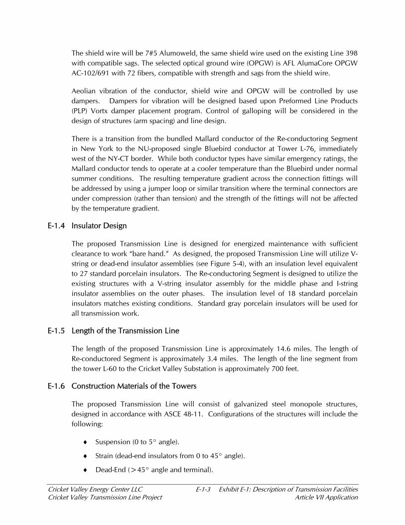
The shield wire will be 7#5 Alumoweld, the same shield wire used on the existing Line 398 with compatible sags. The selected optical ground wire (OPGW) is AFL AlumaCore OPGW AC-102/691 with 72 fibers, compatible with strength and sags from the shield wire.
Aeolian vibration of the conductor, shield wire and OPGW will be controlled by use dampers. Dampers for vibration will be designed based upon Preformed Line Products (PLP) Vortx damper placement program. Control of galloping will be considered in the design of structures (arm spacing) and line design.
There is a transition from the bundled Mallard conductor of the Re-conductoring Segment in New York to the NU-proposed single Bluebird conductor at Tower L-76, immediately west of the NY-CT border. While both conductor types have similar emergency ratings, the Mallard conductor tends to operate at a cooler temperature than the Bluebird under normal summer conditions. The resulting temperature gradient across the connection fittings will be addressed by using a jumper loop or similar transition where the terminal connectors are under compression (rather than tension) and the strength of the fittings will not be affected by the temperature gradient.
E-1.4 Insulator Design
The proposed Transmission Line is designed for energized maintenance with sufficient clearance to work “bare hand.” As designed, the proposed Transmission Line will utilize V-string or dead-end insulator assemblies (see Figure 5-4), with an insulation level equivalent to 27 standard porcelain insulators. The Re-conductoring Segment is designed to utilize the existing structures with a V-string insulator assembly for the middle phase and I-string insulator assemblies on the outer phases. The insulation level of 18 standard porcelain insulators matches existing conditions. Standard gray porcelain insulators will be used for all transmission work.
E-1.5 Length of the Transmission Line
The length of the proposed Transmission Line is approximately 14.6 miles. The length of Re-conductored Segment is approximately 3.4 miles. The length of the line segment from the tower L-60 to the Cricket Valley Substation is approximately 700 feet.
E-1.6 Construction Materials of the Towers
The proposed Transmission Line will consist of galvanized steel monopole structures, designed in accordance with ASCE 48-11. Configurations of the structures will include the following:
Suspension (0 to 5° angle).
Strain (dead-end insulators from 0 to 45° angle).
Dead-End (>45° angle and terminal).

Cricket Valley Energy Center LLC E-1-4 Exhibit E-1: Description of Transmission Facilities Cricket Valley Transmission Line Project Article VII Application
The majority of steel monopoles will have a delta arrangement of insulators. The pole configuration was designed to permit energized work practice – bare hand or hot-stick methods. The clearances will be governed by the National Electrical Safety Code (NESC), latest edition. The NESC provides minimum clearances to ground, adjacent transmission lines, railroads, buildings, and a host of other facilities. Clearances greater than minimum provide additional safety during extreme weather events or accidents. For the proposed Transmission Line, the vertical clearance to ground will be 35 feet, which includes the NESC required clearance of 24.7 feet plus a 10-foot buffer. Vertical and horizontal clearances to objects will be the NESC requirements plus a minimum of 3-foot buffer. Adjustments to this configuration may be needed for the structures nearby the Sky Acres Airport, but in all cases will meet or exceed NESC requirements. The final design will be presented in the EM&CP. Conductor clearance to surface structures will be the NESC requirements plus additional space for working space, climbing space and for energized work practices. The Minimum Approach Distance (MAD) plus 1 foot will also be utilized to determine structure configuration and clearances based upon NESC Table 441-1.
Pole and davit arm sizes vary depending upon loads and required height. Strain poles are included periodically on tangent or low angle structures to provide periodic stronger poles to prevent cascade type events and adjacent to long spans where significant unbalanced loads are likely due to icing events.
Structures on the proposed Transmission Line are essentially a one-to-one match with the existing Line 398 but are offset by 100 feet. Structure locations were adjusted in-line for local terrain conditions (e.g., locations on hilltop are preferred over locations on a slope) and the need to minimize structure heights near the Sky Acres Airport.
For the preliminary foundation design, based on the anticipated shallow depth to rock throughout the right-of-way, it was assumed that rock anchor or rock micropile foundations would be used. A rock anchor foundation functions similarly to a pile group foundation (individual anchors in either tension or compression) except capacity is largely achieved through rock to grout bond. Rock micropile foundations have pretensioned anchor rods, and a steel casing in the upper, non-loaded section (in this case soils). Due to expected access difficulties, an elevated anchor cap assembly will be used instead of a concrete foundation (similar to a pile cap).
The Re-conductoring Segment will utilize Line 398 lattice steel towers with conductors, shield wire, and insulator assemblies replaced. One structure, L-65 requires reinforcement to meet the current NESC Code and the current Consolidated Edison Standards for strength.
E-1.7 Design Standards
The design of the proposed Project will be in accordance with all applicable federal and state requirements, and local codes and industry standards, unless stated otherwise. The industry codes and standards shall include, but shall not be limited to, the following:

Cricket Valley Energy Center LLC E-1-5 Exhibit E-1: Description of Transmission Facilities Cricket Valley Transmission Line Project Article VII Application
ANSI C2, The National Electric Safety Code 2012 (NESC).
ASCE 48-05, Design of Steel Transmission Pole Structures.
ASCE 74, Guidelines for Electrical Transmission Lines Structural Loads.
ASCE 10-97, Design of Latticed Steel Transmission Structures.
Con Edison Transmission Standards (CE-SS-2006).
E-1.7.1 Structural Loading
The structural loading design criteria for both the proposed Transmission Line and Re-conductoring Segment will be in accordance with NESC and Con Edison requirements, consisting of the following:
Case 1A, - NESC 250B Loads & Load Factors for Heavy Ice District, Grade B Construction.
Case 1B – NESC 250C, Loads & Load Factors for Extreme Winds in Area, Exposure Category C. Details provided in NESC Code.
Case 1C – NESC 250D, Loads & Load Factors for Extreme Ice with Concurrent Wind. Use ¾ inch ice and 50 mph wind.
Case 2A – 100 year ice loading, 1 inch ice and 8 psf wind pressure on wires and steel poles.
Case 2B – 100 year wind, 1.2 times the basic wind pressure from NESC 250C. Wind pressure adjusted for height (SAPS Wind).
Case 3A – Unbalanced Ice, ½ inch radial ice applied to front or back spans, 4 psf wind on wires and steel poles.
Case 3B – Longitudinal broken wire condition, 1 broken shield wire or 1 broken conductor (all wires in bundle), no wind condition.
Case 4A – Stringing condition, dead-end structures - Dead-end loading, all wires dead-ended, 2 psf wind, nominal stringing tension and a 1.3 load factor.
Case 4A - Stringing condition, strain structures - Dead-end loading, one conductor bundle or one shield wire dead-ended, 2 psf wind, nominal stringing tension and a 1.3 load factor.
Case 4B – Stringing condition, strain or dead-end structure - One conductor bundle or one shield wire @ 60° Vector loading. Longitudinal unbalanced load and vertical load increase, 2 psf wind, nominal stringing tension and a 1.3 load factor.
Case 4B – Stringing condition, suspension structure - one conductor bundle or one shield wire @ 30° Vector loading. Longitudinal unbalanced load and vertical load increase, 2 psf wind, nominal stringing tension and a 1.3 load factor.
All loads for intact load cases (Cases 1 & 2) are increased by the transverse loads associated with a 2 degree line angle.

Cricket Valley Transmission Line
and Re-conductoring Project
Exhibit E-2
Other Facilities

Cricket Valley Energy Center LLC E-2-1 Exhibit E-2: Other Facilities Cricket Valley Transmission Line Project Article VII Application
EXHIBIT E-2 OTHER FACILITIES
This Exhibit addresses the requirements of 16 NYCRR §88.2.
Cricket Valley Energy Center, LLC (“Cricket Valley”) is proposing to: (1) develop a new approximately 14.6-mile 345 kV transmission line parallel to the existing Consolidated Edison Company of New York, Inc.’s (“Con Edison”) 345 kV Transmission Line 398 (“Line 398”) from the planned Cricket Valley switchyard (the “Cricket Valley Switchyard”) in the town of Dover, New York to Con Edison’s Pleasant Valley Substation in the town of Pleasant Valley, New York (the “Transmission Line”); and (2) re-conductor an approximately 3.4-mile segment of the existing 345 kV Transmission Line 398 in the town of Dover between the Cricket Valley Switchyard and the New York-Connecticut state line (the “Re-conductoring Segment”) (collectively the “Project”).
The Project will also include improvements to Consolidated Edison’s Pleasant Valley Substation. New protection and communication system upgrades will be required within the existing control buildings at the Pleasant Valley Substation.
The proposed modifications to the Pleasant Valley Substation and existing Line 398 for the Project are described herein.
E-2.1 Pleasant Valley Substation
E-2.1.1 Existing Facility
The Pleasant Valley Substation is an open air 345-138kV substation, with seven (7) 345 kV lines terminating in four bays in a breaker-and-a-half arrangement with a 345-138 kV transformer feeding an adjacent 138 kV substation.
E-2.1.2 Proposed Modifications
The Project will adhere to Con Edison design standards as well as reference, IEEE and widely-accepted industry standards. These standards will be used for the modifications at the Pleasant Valley Substation as follows.
a. Materials
Materials to be used include.
HVB 362 kV, 63 KA, 2 cycle, 1300 kV BIL, SF-6 circuit breaker with 2 - 3000: 5 CT'S per bushing to include a TRV Capacitor per bushing.
362 kV, 5000 A, 100 KA, 1300kV BIL Double End Break Disconnect Switch 3-Phase.
3-362 kV, 100 KA Ground Switch, single phase.
Cricket Valley Energy Center LLC E-2-2 Exhibit E-2: Other Facilities Cricket Valley Transmission Line Project Article VII Application
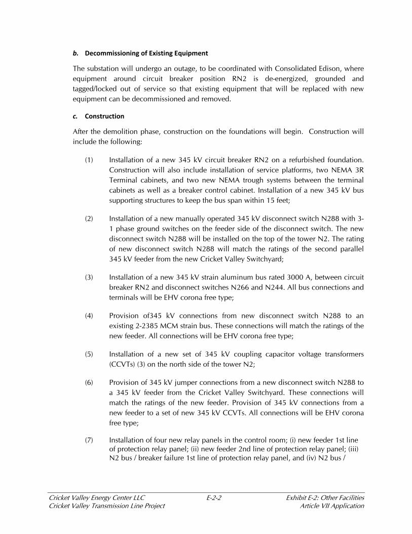
b. Decommissioning of Existing Equipment
The substation will undergo an outage, to be coordinated with Consolidated Edison, where equipment around circuit breaker position RN2 is de-energized, grounded and tagged/locked out of service so that existing equipment that will be replaced with new equipment can be decommissioned and removed.
c. Construction
After the demolition phase, construction on the foundations will begin. Construction will include the following:
(1) Installation of a new 345 kV circuit breaker RN2 on a refurbished foundation. Construction will also include installation of service platforms, two NEMA 3R Terminal cabinets, and two new NEMA trough systems between the terminal cabinets as well as a breaker control cabinet. Installation of a new 345 kV bus supporting structures to keep the bus span within 15 feet;
(2) Installation of a new manually operated 345 kV disconnect switch N288 with 3-1 phase ground switches on the feeder side of the disconnect switch. The new disconnect switch N288 will be installed on the top of the tower N2. The rating of new disconnect switch N288 will match the ratings of the second parallel 345 kV feeder from the new Cricket Valley Switchyard;
(3) Installation of a new 345 kV strain aluminum bus rated 3000 A, between circuit breaker RN2 and disconnect switches N266 and N244. All bus connections and terminals will be EHV corona free type;
(4) Provision of345 kV connections from new disconnect switch N288 to an existing 2-2385 MCM strain bus. These connections will match the ratings of the new feeder. All connections will be EHV corona free type;
(5) Installation of a new set of 345 kV coupling capacitor voltage transformers (CCVTs) (3) on the north side of the tower N2;
(6) Provision of 345 kV jumper connections from a new disconnect switch N288 to a 345 kV feeder from the Cricket Valley Switchyard. These connections will match the ratings of the new feeder. Provision of 345 kV connections from a new feeder to a set of new 345 kV CCVTs. All connections will be EHV corona free type;
(7) Installation of four new relay panels in the control room; (i) new feeder 1st line of protection relay panel; (ii) new feeder 2nd line of protection relay panel; (iii) N2 bus / breaker failure 1st line of protection relay panel, and (iv) N2 bus /

Cricket Valley Energy Center LLC E-2-3 Exhibit E-2: Other Facilities Cricket Valley Transmission Line Project Article VII Application
breaker failure 2nd line of protection relay panel. Relay panels construction and design will match existing relay panels in the room, and will be installed in vacant positions allocated for the panels in station's original design;
(8) Provision of control and indication circuits for a new 345 kV circuit breaker RN2 and existing disconnect switches N244 and N266. The new control switches would be located on the front of N2 bus and breaker failure 2nd line of protection relay panel, and will allow for remote and local operation. Existing supervisory control and indication for a new 345 kV circuit breaker RN2 and existing disconnect switches N244 and N266 on station's mimic board and via EMS should be modified if necessary to meet current design guidelines described in CE-ES-2002, Section III, Part I, latest revision;
(9) Provision of alarms from the new 345 kV circuit breaker RN2 and relay panels in accordance with current design guidelines described in CE-ES- 2002, and Section III, Part 34, latest revision. All new alarms will be consistent with existing alarms throughout the substation;
(10) Provision of AC and DC supplies to the new 345 kV circuit breaker RN2 and relay panels as required. Provision of new or modify existing AC and DC distribution panels if necessary;
(11) Provision ground connections to all new equipment, supporting structures, service platforms, control cabinets, etc. according to design guidelines; CE-ES-2002 Section III, part 10, latest revision;
(12) Verify that all new installations are protected against the lightning in accordance with IEEE998 Guidelines for Direct Lightning Stroke Shielding of Substations;
(13) Install and test Protection and Control equipment in control house. The Protection and Control (P&C) design will include the following schemes and equipment:
a) Main protection scheme: Current Differential detection on the PV2CV line.
b) Back-up protection scheme: Stepped Distance on the PV2CV line.
c) Primary relaying will utilize an AREVAP546 relay.
d) Secondary relaying will utilize an SEL 411L relay.
e) Redundant channels will be used for inter-relay communications between Pleasant Valley and Cricket Valley systems.

Cricket Valley Energy Center LLC E-2-4 Exhibit E-2: Other Facilities Cricket Valley Transmission Line Project Article VII Application
f) Communications Channel 1 will be on a Con Ed CCTN T1 circuit via a RFL IMUX 2000.
g) Communications Channel 2 will be on a leased Verizon T1 circuit via a RFL IMUX 2000.
h) Direct Transfer trip for Breaker Failure protection will be provided in the 1st line feeder relays (P546) and the 2nd line feeder relays (SEL 411L) using the same communication channels as that for their respective current differential scheme.
i) GPS clock synchronization will be provided on the new relays.
d. Testing and Commissioning
Testing and commissioning will be performed and supervised by experienced Con Ed staff at both the new Cricket Valley Switchyard and the Pleasant Valley Substation. The commissioning of the connections from the new P&C equipment to the existing SCADA equipment will be performed by experienced Con Edison staff, according to Con Edison standard practices.
E-2.2 Connection to Existing Line 398
E-2.2.1 Existing Facility
The existing Line 398 is a single circuit 345kV transmission line extending from Consolidated Edison’s Pleasant Valley Substation to the New York (NY)-Connecticut (CT) border, whereupon Northeast Utilities Service Company owns Line 398 from the NY-CT border to their Long Mountain Substation in Connecticut. The New York portion of Line 398 currently consists of 2156 kcmil 84/19 ASCR conductor with two 7#5 ALWD shield wires. The line is constructed using lattice steel structures, horizontal line arrangement with overhead shield wires
E-2.2.2 Proposed Modifications
The Project will adhere to Con Edison design standards as well as reference, IEEE and widely-accepted industry standards. These standards will be used for the reconductoring of Line 398 as follows.
a. Materials
Materials for the proposed modifications include the following:
Steel pole L-60-1 Double Circuit double dead end tap pole with a vertical configuration.
Steel pole L-60-2 Double Circuit Dead-End angle structure.
Cricket Valley Energy Center LLC E-2-5 Exhibit E-2: Other Facilities Cricket Valley Transmission Line Project Article VII Application
Take-off structure at the new Cricket Valley Substation. Double circuit horizontal configuration.
Drilled pier or rock anchor foundation for the pole structures.
Insulators, hardware and grounding associated with steel poles.
b. Construction
Construction will include the following, and outages will be coordinated with Consolidated Edison as required:
Loop Feeder 398 through the new Cricket Valley Switchyard, whereupon upon the segment from the new Cricket Valley Switchyard to Long Mountain is conductored (or re-conductored) with bundled “Mallard” 795 Aluminum Conductor Steel Supported (ACSS) and the conductor segment from the new Cricket Valley Switchyard to Pleasant Valley remains as 2156 kcmil 84/19 ASCR. The 7 #5 shield wire remains for Pleasant Valley to the New York/Connecticut border.
Replace Structure L-60 with a double dead end T configuration pole (see attached Figure E-2-3). The line continues from new structure L-60-1 to a double circuit dead-end pole L-60-2 then to the take-off structure at the new Cricket Valley Switchyard.

Cricket Valley Energy Center
Cricket Valley Transmission Line
and Re-conductoring Project
Exhibit E-2 - Figures
The drawings within Exhibit E-2 (Figures E-2-1 and E-2-2) are considered protected critical infrastructure information. In accordance with Public Officers Law, Sections 89.5(a)(1)(1-a) and 87.2(f), and Section 6-1.3 of the Public Service Commission’s regulations, CVEC has requested that these drawings be excepted from public disclosure by the Commission.

Figure E-2-1 Con Edison Pleasant Valley 345 kV Switch Station REDACTED

Figure E-2-2 Con Edison Pleasant Valley Bay 2, RN2 Breaker REDACTED

Figure E-2-3 Structure L-60-1 Double Dead-End Tap Pole
Cricket Valley Transmission Line
and Re-conductoring Project
Exhibit E-3
Underground Construction

Cricket Valley Energy Center LLC E-3-1 Exhibit E-3: Underground Construction Cricket Valley Transmission Line Project Article VII Application
EXHIBIT E-3 UNDERGROUND CONSTRUCTION
This Exhibit addresses the provisions of 16 NYCRR §88.3.
E-3.1 General
Cricket Valley Energy Center, LLC (“Cricket Valley”) is proposing to: (1) develop a new approximately 14.6-mile 345 kV transmission line parallel to the existing Consolidated Edison Company of New York, Inc.’s (“Con Edison”) 345 kV Transmission Line 398 (“Line 398”) from the planned Cricket Valley switchyard (the “Cricket Valley Switchyard”) in the town of Dover, New York to Con Edison’s Pleasant Valley Substation in the town of Pleasant Valley, New York (the “Transmission Line”); and (2) re-conductor an approximately 3.4-mile segment of the existing 345 kV Transmission Line 398 in the town of Dover between the Cricket Valley Switchyard and the New York-Connecticut state line (the “Re-conductoring Segment”) (collectively the “Project”).
The Project will also include improvements to Consolidated Edison’s Pleasant Valley Substation. New protection and communication system upgrades will be required within the existing control buildings at the Pleasant Valley Substation.
As described throughout this application, the Project proposes construction of an overhead transmission line, and accordingly, no significant underground facilities will be required for the Project, with the exception of duct banks or vaults within the existing Pleasant Valley Switchyard. As part of the engineering design of the Project, minor appurtenances such as a ground wire grid and cathodic protection of the existing natural gas pipeline that crosses the Project right-of-way will be installed beneath the ground surface within the right-of-way, representing the only subsurface components of the Project.

Cricket Valley Transmission Line
and Re-conductoring Project
Exhibit E-4
Engineering Justification
Cricket Valley Energy Center LLC E-4-1 Exhibit E-4: Engineering Justification Cricket Valley Transmission Line Project Article VII Application
EXHIBIT E-4 ENGINEERING JUSTIFICATION
This exhibit addresses the requirements of 16 NYCRR §88.4.
E-4.1 Introduction
Cricket Valley Energy Center, LLC (“Cricket Valley”) is proposing to: (1) develop a new approximately 14.6-mile 345 kV transmission line parallel to the Consolidated Edison Company of New York, Inc.’s (“Con Edison”) 345 kV Line 398 (“Line 398”) from the planned Cricket Valley switchyard (the “Cricket Valley Switchyard”) in the town of Dover, New York to Con Edison’s Pleasant Valley Substation in the town of Pleasant Valley, New York (the “Transmission Line”); and (2) re-conductor an approximately 3.4-mile segment of the existing 345 kV Line 398 in the town of Dover between the Cricket Valley Switchyard and the New York-Connecticut state line (the “Re-conductoring Segment”). The proposed Transmission Line and the Re-conductoring Segment (collectively, the “Project”) will be located entirely within the existing Con Edison Line 398 right-of-way.
On February 14, 2013, the New York Public Service Commission (“PSC” or the “Commission”) granted a Certificate of Public Convenience and Necessity (“CPCN”) to Cricket Valley’s combined cycle, natural gas-powered 1,000 megawatt (“MW”) electric generating facility in Dover, New York (the “Generation Facility”), finding that the Generation Facility: (i) is needed to help meet long-term electric capacity needs; (ii) will improve overall generation efficiency and fuel consumption in of the New York State; (iii) provide blackstart benefits; and (iv) will help lower air emissions, provide more cost-effective electricity and improve reliability throughout the region.
As a condition of the CPCN, Cricket Valley is obligated to design, engineer, and construct facilities in support of the Generation Facility in accordance with the New York Independent System Operator (“NYISO”) Class Year 2011 Facilities Studies System Upgrade Facilities Initial Round Report dated July 9, 2013 (“SUF Report”), or such later study as may be applicable. During the 2011 Class Year study process for the Generation Facility, NYISO determined that the Project is a system upgrade facility (“SUF”) necessary to allow the Generation Facility to interconnect with the grid without adversely impacting the operability, reliability, stability, or transfer limits of the system.
The Project increases overall system reliability, maintains acceptable levels of transfer capability when the Generation Facility is in operation, and will increase the capability of the transmission system to transfer power between ISO-NE and NYISO under specific operating conditions. Depending on the actual dispatch of the transmission system and nearby generation (including the Generation Facility), additional transfer capability may be available between the two regions, thereby creating opportunities for additional economic transfers of power as well as capability for transfers of emergency energy and reserve sharing.
Cricket Valley Energy Center LLC E-4-2 Exhibit E-4: Engineering Justification Cricket Valley Transmission Line Project Article VII Application
E-4.2 Description of Existing 345KV Transmission Line (Line 398)
The existing cross-ISO tie line between the Pleasant Valley Substation in Pleasant Valley, New York and the Long Mountain Substation in New Milford, Connecticut consists of an approximately 18 mile 345kV overhead transmission line segment of Line 398 owned and operated by Con Edison and a 5.6 mile 345kV overhead transmission line segment owned and operated by Northeast Utilities of Connecticut (“NU”). The NY-NE interface, including the existing line, provides an export transfer capability of 947 MW, and an import transfer capability of 1,518 MW under specific studied scenarios (SUF Report, Table 2.1.2.1).
Line 398 was originally constructed in 1964, within a nominal 250-foot right-of-way maintained by Con Edison in New York. The centerline of Line 398 is offset 50 feet north of the right-of-way centerline, leaving sufficient room to install a second set of conductors 50 feet south of the right-of-way centerline. The existing Line 398 conductors are supported by lattice-type towers and arranged in a horizontal configuration from the Pleasant Valley Substation to the NY/CT border. The 5.5 miles of conductors owned by NU in Connecticut are supported by H-frame structures.
E-4.3 Need for the Proposed Project
E-4.3.1 Cricket Valley Energy Center (Generation Facility)
Cricket Valley is developing the Generation Facility in Dover, NY on property immediately adjacent to the Line 398 right-of-way. Cricket Valley has received all major pre-construction permits for the Generation Facility, including a CPCN. The Commission determined, amongst other benefits, that the Generation Facility is in the public interest, and further that, “as an additional source of power generation in the Hudson Valley, the project will help meet long-term electric system capacity needs and may relieve short term reliability concerns due to generation retirement.” As noted above, the CPCN also found electricity cost, fuel consumption, generation efficiency, emission reduction, and black start benefits would be created by the operation of the Generation Facility.
As further support of the Project’s need justification, and pursuant to PSL Section 126.1(d), the Project conforms to a long-rage plan for expansion of the electric power grid serving the state and interconnected electric systems. In its CPCN filing with the Commission, Cricket Valley explained that the Generation Facility promotes objectives contained in the 2009 New York State Energy Plan. In its CPCN petition, Cricket Valley stated that: The 2009 State Energy Plan identified five policy objectives:
Maintain Reliability: Assure that New York has reliable energy and transportation systems;

Cricket Valley Energy Center LLC E-4-3 Exhibit E-4: Engineering Justification Cricket Valley Transmission Line Project Article VII Application
Reduce Greenhouse Gas (“GHG”) Emissions: Support energy and transportation systems that enable the State to significantly reduce GHG emissions, both to do the State’s part in responding to the dangers posed by climate change and to position the State to compete in a national and global carbon-constrained economy;
Stabilize Energy Costs and Improve Economic Competitiveness: Address affordability concerns of residents and businesses caused by rising energy bills, and improve the State’s economic competitiveness;
Reduce Public Health and Environmental Risks: Reduce health and environmental risks associated with the production and use of energy across all sectors; and
Improve Energy Independence: Improve the State’s energy independence and fuel diversity by developing in-state energy supply resources.1
The Cricket Valley Facility will assist New York State in achieving the State Energy Plan’s objectives. The 2009 State Energy Plan explains:
[i]n general, new plants use technologies that are more efficient than those used in older plants. As older facilities retire and newer, more efficient plants come on line, the average heat rate of the power plant fleet in New York is expected to improve. The State’s markets and its commitment to continually improve them will facilitate this substitution.2
The Commission’s findings that the Generation Facility was in the public interest for several key reasons implicitly adopted this analysis.
In addition, NYISO’s Congestion Assessment and Relief Integration Study (“CARIS”), dated March, 2012, specifically identified the addition of 1,000M W of generation in the area of the ConEd Pleasant Valley substation - the exact substation at which the Project will connect the Generation Facility- as a solution to reduce congestion in New York State in the Leeds-Pleasant Valley transmission corridor. NYISO estimates that placement of a 1,000 MW generation facility adjacent to the Pleasant Valley substation will produce an estimated ten-year electricity production cost savings of $330 million (present value).
The generation solution [for the Leeds-Pleasant Valley congestion] is projected to reduce congestion across NYCA for the planning horizon. The ten-year production cost savings of $330 million (present value) are due to the uncongested location and the assumed better
1 State Energy Planning Board, 2009 State Energy Plan: Volume I, at xiii (2009), available at http://www.nysenergyplan.com/final/New_York_State_Energy_Plan_VolumeI.pdf., at 33.
Cricket Valley Energy Center LLC E-4-4 Exhibit E-4: Engineering Justification Cricket Valley Transmission Line Project Article VII Application
heat rate of the generic generating unit compared to the average system heat rate. Efficient generator solutions reduce imports from neighbors and enable a more efficient and lower cost NYCA generation market. Savings accrue in lower production cost as well as reduced congestion (CARIS, Page 54). In addition, the Phase 1 NYISO 2013 CARIS Report increased the recommended generation solution to relieve transmission congestion to a 1320 MW generation facility at Pleasant Valley which would reduce congestion by 18% in 2017 and 31% in 2022. Even though the estimated ten-year electricity production cost savings was revised down to $231 million (present value), the 2013 CARIS Report shows that the Pleasant Valley generation solution produces higher production cost savings in the aggregate over a ten year period than alternative transmission solutions.
The Generation Facility will be located approximately 14 miles east of the Con Edison Pleasant Valley Substation and, electrically, is closely equivalent to the generic generator solution studied by NYISO. Thus, Cricket Valley anticipates that the Project will generate $231-$330 million in production cost savings identified in CARIS for the benefit of New York State ratepayers.
Finally, the Commission found in the CPCN order that “…the new facility is expected to provide cost effective electricity with lower emissions than most existing generating facilities.”
E-4.3.2 The Generation Facility Electrical Interconnection to the NYISO Grid
All new generation projects must submit an interconnection request to NYISO to determine what, if any, network upgrades are required to reliably deliver the incremental power into the grid. Once an interconnection request is initiated by a developer of a new generation project and the project has achieved certain milestones specified by NYISO, NYISO begins a series of detailed studies to determine the scope, cost and feasibility of the required upgrades. These studies culminate in the Facilities Study, where a definitive set of network upgrades and associated cost responsibilities are determined. The final, NYISO-approved ”Class Year 2011 Facilities Studies System Upgrade Facilities (SUF)” Study, incorporates the impacts of all proposed new generation included in the Class Year 2011 projects, and presents final determinations on required network upgrades attributable to each proposed new generation project in Class Year 2011.
As a result of the Class Year 2011 study process detailed above, and in accordance with the applicable rules and requirements set forth under the Open Access Transmission Tariff (“OATT”), NYISO determined that a direct interconnection of the Generating Facility into the existing Line 398 would result in a degradation of transfer limits that could not be managed through normal operating procedures. As a consequence, NYISO determined that the addition of the Generation Facility into the existing transmission system (without the Project) would have adverse operability and reliability impacts and certain system upgrades would be required to mitigate such impacts.
Cricket Valley Energy Center LLC E-4-5 Exhibit E-4: Engineering Justification Cricket Valley Transmission Line Project Article VII Application
Specifically, NYISO and ISO-NE Inc. (“ISONE”) studied and compared the performance of the transmission system both with and without the proposed Project. This included study of the system under normal conditions (all system elements in-service) and under specific contingencies representing loss of system elements (referred to as the N-1 analysis).
E-4.3.2.1 N-1 Transfer Impacts
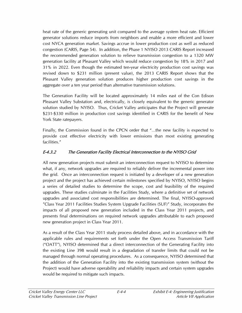
Table E-4-1 shows calculated thermal transfer import (NE-NY) limits on Line 398 with and without the addition of the Generation Facility during peak load conditions under normal and emergency conditions.
Table E-4-1 Normal and Emergency Thermal Transfer Import Limits on the NY-NE Interface Under Peak Load Conditions
Existing Transmission
Line Transfer Limits
(MW)
Existing Transmission
Line Transfer Limits
with CVEC
(MW)
Change in Transfer
Limits with CVEC
(MW)
Normal Limits 1518 620 -898
Emergency Limits 2598 1224 -1374
Source: SUF Report, Table 2.1.2.1
Table E-4-2 shows calculated normal and emergency thermal transfer export (NY-NE) limits on the existing interface with and without the addition of CVEC during peak load conditions.
Table E-4-2 Normal and Emergency Thermal Transfer Export Limits on the NY-NE Interface Under Peak Load Conditions
Existing Transmission
Line Transfer Limits
(MW)
Transmission Line
Transfer Limits with
CVEC
(MW)
Change in Transfer
Limits with CVEC
(MW)
Normal Limits 947 610 -337
Emergency Limits 1490 1155 -335
Source: SUF Report, Table 2.1.2.1
NYISO determined that the degradation of import and export transfer capability of the cross-ISO interface directly attributable to the Generation Facility resulted in adverse effects on the reliability of the system, and would have to be addressed appropriately with system upgrade facilities.

Cricket Valley Energy Center LLC E-4-6 Exhibit E-4: Engineering Justification Cricket Valley Transmission Line Project Article VII Application
Under the system condition where the Pleasant Valley-to-Cricket Valley segment of Line 398 has been lost or is otherwise out of service, the entirety of the Generation Facility’s output would be forced onto the ISO-NE system. In this scenario, the NY-NE import capability is adversely impacted due to overloading of the Norwalk Northport Cable (“NNC”) across Long Island Sound. This condition is of particular concern to ISO-NE because they have no direct operational dispatch control over the Generation Facility as it is part of the NYISO system.
E-4.3.2.2 NYISO System Upgrade Facilities Determination
Based on the unacceptable degradation of thermal transfer limits and the cross-ISO reliability concerns described above, NYISO initially identified two potential solutions to address the impacts:
Option 1: Re-conductoring of Pleasant Valley to Cricket Valley to Long Mountain, along with upgrading the NNC Path elements (i.e., the Northport PAR, the Norwalk autotransformer, and the three 138 kV Norwalk CT to Northport Long Island NY submarine cables).
Option 2: Adding a second Pleasant Valley to Cricket Valley 345 kV line, while re-conductoring the Cricket Valley to Long Mountain 345 kV segment (the Project proposed here).3
Based on the subsequent feedback received from the Long Island Power Authority (“LIPA”) ISONE, NU, and Con Edison, NYISO concluded that Option 1 is unacceptable. Without a second tie line, the Generation Facility will continue to be isolated into ISO-NE’s system for a single contingency (i.e.: loss of the segment of Line 398 between Pleasant Valley and the Generation Facility), with 40% of the flow being picked up by LIPA (via Connecticut and the NNC Path), while ISONE has no operational control over the Generation Facility.
After rejection of Option 1, NYISO concluded that Option 2 was the only viable method to properly mitigate the operability and reliability concerns identified. As such, the Project is required by NYISO as an SUF for the Generation Facility, as it mitigates the effects of isolating the project into ISO-NE territory and restores the NE to NY interface thermal limits to an acceptable level. (SUF Report, Section 2.1.2.1, Pages 27-28)
3 The 3.4 mile New York State element of the re-conductoring is included in this application. The 5.6 mile Connecticut portion is being permitted and constructed by NU.
Cricket Valley Energy Center LLC E-4-7 Exhibit E-4: Engineering Justification Cricket Valley Transmission Line Project Article VII Application
E-4.4 Proposed Project Benefits
The major System Upgrade Facilities for the Project, as required by NYISO, include:
Modifications to Bay 2 of the Pleasant Valley Substation, including a new breaker, coupling capacitance voltage transformers (CCVT), miscellaneous ancillaries and controls integration;
Sixty-one (61) new steel monopole support structures located in the existing Line 398 right-of-way; from the Cricket Valley Switchyard to the Pleasant Valley Substation
Bundled 795 kcmil Aluminum Conductor Steel Supported (ACSS) Mallard conductors for the Transmission Line and Re-conductoring Segment;
Gas Insulated Switchgear (GIS) at the new Cricket Valley Switchyard, complete with a ring bus breaker configuration, surge arrestors, disconnects, grounding switches and miscellaneous ancillary electrical equipment consistent with Con Edison design requirements (the Cricket Valley Switchyard was approved by the Commission in the CPCN);
One (1) new steel monopole and two (2) new take-off structures between the existing Con Edison Line 398 right-of-way and the Cricket Valley Switchyard;
Structural reinforcement of the existing tower L-65 on the Re-conductoring Segment.
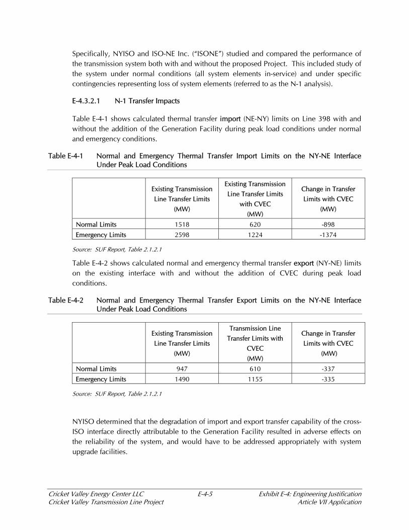
Table E-4-3 shows calculated normal and emergency thermal transfer import limits on the NY-NE interface, with and without the addition of the Generation Facility and the Project during peak load conditions.
Table E-4-3 Thermal Transfer Import Limits on the NY-NE Interface Under Peak Load Conditions
Existing Transmission
Line Transfer Limits
(MW)
Transmission Line
Transfer Limits with
CVEC and the
Transmission Project
(MW)
Change in Transfer
Limits with CVEC and
the Transmission
Project
(MW)
Normal Limits 1518 1228 -290
Emergency Limits 2598 2129 -469
Source: SUF Report, Table 2.1.2.1

Cricket Valley Energy Center LLC E-4-8 Exhibit E-4: Engineering Justification Cricket Valley Transmission Line Project Article VII Application
Table E-4-4 shows calculated normal and emergency thermal transfer export limits on the NY-NE interface, with and without the addition of CVEC and the Transmission Project during peak load conditions.
Table E-4-4 Thermal Transfer Export Limits on the NY-NE Interface Under Peak Load Conditions
Existing Transmission
Line Transfer Limits
(MW)
Transmission Line
Transfer Limits with
CVEC and the
Transmission Project
(MW)
Change in Transfer
Limits with CVEC and
the Transmission
Project
(MW)
Normal Limits 947 1188 +241
Emergency Limits 1490 1602 +112
Source: SUF Report, Table 2.1.2.1
As summarized in the above tables and as determined by NYISO in its SUF Study, the Project is the only solution that has the effect of mitigating identified reliability concerns, and restoring the thermal import and export limits to an acceptable level. The determined solution is, therefore, a requirement for interconnection of Generation Facility into the transmission system.
E-4.5 Impact of a Delay in the Construction Schedule
The Generation Facility is currently scheduled for a commercial operation date of January 1, 2018, which requires the Project to be completed and in-service no later than June 1, 2017 to allow for enough time to properly commission the facility. A delay in the construction schedule of the Project could create a delay in the commissioning, startup and commercial operation of the Generation Facility. As stated by the Commission in the CPCN, the Generation Facility will help meet long-term electric system capacity needs and may relieve short term reliability concerns due to generation retirement. A delay in the construction schedule of the Project could, therefore, have an adverse impact on short-term system reliability.

Cricket Valley Transmission Line
and Re-conductoring Project
Exhibit E-5
Effect on Communications

Cricket Valley Energy Center LLC E.5-1 Exhibit E-5: Effect on Communications Cricket Valley Transmission Line Project Article VII Application
EXHIBIT E-5 EFFECT ON COMMUNICATIONS
This exhibit addresses the provisions of 16 NYCRR §88.5.
E-5.1 Introduction
Cricket Valley Energy Center, LLC (“Cricket Valley,” “the Applicant”) is proposing to: (1) develop a new approximately 14.6-mile 345 kV transmission line parallel to the existing Consolidated Edison Company of New York, Inc.’s (“Con Edison”) 345 kilovolt (“kV”) Transmission Line 398 (“Line 398”) from the planned Cricket Valley switchyard (the “Cricket Valley Switchyard”) in the town of Dover, New York to Con Edison’s Pleasant Valley Substation in the town of Pleasant Valley, New York (the “Transmission Line”); and (2) re-conductor an approximately 3.4-mile segment of the existing 345 kV Transmission Line 398 in the town of Dover between the Cricket Valley Switchyard and the New York-Connecticut state line (the “Re-conductoring Segment”) (collectively the “Project”).
The Project will also include improvements to Consolidated Edison’s Pleasant Valley Substation. New protection and communication system upgrades will be required within the existing control buildings at the Pleasant Valley Substation.
The Project right-of-way crosses through the towns of Dover, Union Vale, La Grange, and Pleasant Valley, all located in Dutchess County, New York.
E-5-2 Description of Effects on Communication
Communication interference associated with transmission lines is generally attributable to two electronic frequency phenomena; gap noise and corona discharge. “Gap noise” can occur on transmission lines of any voltage. It is caused by loose connections or broken insulators that create an electrical spark or arc. “Corona discharge” is generally a concern for transmission lines operating at 230 kV and higher; it is the ionization of the air near the surface of a conductor.
As a general matter, the transmission improvements are not expected to have adverse effects on communications (i.e., television, radio, cell phone, cable, fiber optic, etc.) during either construction or operation. All design and construction work will comply with applicable sections of the latest version of the National Electrical Safety Code (NESC) related to appropriate spacing between power and communication cables. Adequate separation between the Transmission Line and existing communication facilities will be maintained. As part of the final design and the development of the EM&CP, third parties that have communication cables within or adjacent to the Line 398 right-of-way (e.g., Verizon, Frontier Communications, Time Warner Cable) will be consulted to ensure that the precise location of the communication facilities are shown on the construction drawings and that appropriate clearances are provided.
Cricket Valley Energy Center LLC E.5-2 Exhibit E-5: Effect on Communications Cricket Valley Transmission Line Project Article VII Application
With respect to operations, the new transmission line and ancillary facilities are not expected to result in any interference with radio or TV reception. The Transmission Line will be designed with high voltage hardware, twin bundled conductor and increased phase spacing, all of which decrease the potential for electrical interferences associated with corona discharges. Nevertheless, Cricket Valley will be sensitive to complaints of suspected radio interference which may be the result of unintended nicks on the conductor, a sharp corner or loose insulators, none of which are expected. Cricket Valley will investigate and resolve any incidences of interference from the proposed transmission line until ownership of the Transmission Line is transferred to the transmission owner.
Additional specifics are provided in the balance of this Exhibit.
Communications Facilities Mapping
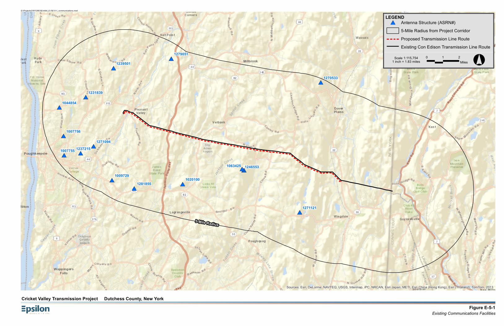
Existing communications facilities within five miles of the Project have been located using the Federal Communication Commission ("FCC") on-line Antenna Structure Registration (ASR) search database and visual observations made during other field surveys. Existing communications facilities are mapped on Figure E-5-1 with a tabular summary provided as Table E-5-1.
Fiber Optic
The signals transmitted by fiber optic cables are not distorted by any form of outside electronic, magnetic or radio frequency interference. Therefore, no impacts to the operations of the fiber optic cable are anticipated with the operations of the proposed transmission system improvements.
Mobile (Cellular) Phone Interference
Digital phones are not known to be subject to interference from transmission lines. There are no cellular antennas within approximately 7,000 ft. of the Line 398 right of way (See Figure E-5-1).
Telephone Interference (Landline)
Traditional telephone cables are normally manufactured with shielded copper wire designed to minimize the potential for transmission line interference. Digital and fiber optic telephone communications are not known to be subject to transmission interference. Nevertheless, as described above, the Project will identify existing phone lines in the vicinity of the right-of-way and ensure that appropriate clearances are maintained.

Cricket Valley Energy Center LLC E.5-3 Exhibit E-5: Effect on Communications Cricket Valley Transmission Line Project Article VII Application
Microwave and other Communications Interferences
In general, microwave communication is not affected by transmission line interference. This assumes that no transmission structures are located in the center of a microwave path. As shown in Table E-5-1, there are no microwave communications facilities in the vicinity of the Project.
Television Interference
In the past, analog television signals were generally broadcast using AM for video and FM for audio. Video signals can be subject to transmission line corona interference if the receiver is within close proximity to transmission lines. FM audio signals are not known to be subject to corona interference. More importantly, since 2009, all television signals are required to be broadcast as digital signals. Digital signals are not subject to corona interference; accordingly, the Project should not cause television interference. Similarly, cable and satellite television signals are not known to be affected by to corona interference.
FM Radio Interference
Frequency Modulated ("FM") radio signals are not known to be affected by transmission line corona interference.
AM Radio Interference
Traditional Amplitude Modulated ("AM") radio signals can be susceptible to transmission line interference. Degradation of a radio signal from external influences is commonly referred to as radio noise. Radio noise resulting from proximity to an electrical transmission line is a complex function of conductor size, surface conditions, spacing, operating voltage and meteorological conditions. Also, as the conductor ages, surface imperfections tend to be smoothed out by weathering, resulting in a reduction of a few decibels in noise as compared to the levels when the line is new.
AM radio interference is generally experienced near the transmission line but decreases rapidly with distance. The Project will provide modeling of potential corona and field levels in the EM&CP to be submitted in 2014. The modeling will use IEEE modeling methods for a typical tangent structure and the proposed conductor.
Railway Signaling System Interference
Transmission lines have been known to cause interference with railway signaling and communication facilities, particularly in instances where the transmission line parallels the track/signaling systems. In this case, the Project will cross an active Metro North rail line at a point about 2,000 ft northwest of the intersection of Route 22 and Cricket Hill Road. As
Cricket Valley Energy Center LLC E.5-4 Exhibit E-5: Effect on Communications Cricket Valley Transmission Line Project Article VII Application
shown in Figure E-5-2 the rail line crosses the Line 398 right-of-way at an oblique angle. The Project will consult with the Metro North and Consolidated Edison to verify that there is no record of signal system interference from the existing 345 kV line.
Sky Acres Airport
Cricket Valley has consulted with Sky Acres Airport and verified that there is no there is no system interference from the existing 345 kV line.

Cricket Valley Energy Center LLC E-5-5 Exhibit E-5: Effect on Communications Cricket Valley Transmission Line Project Article VII Application
Table E-5-1 Communications Towers within 5 Miles of the Project
ASRN # File Number
Structure Type Lat/Long Antenna Structure Address Owner Name
1007755 A0568728 2TA1 - Antenna Tower Array - 1st N = # towers 2nd N
41-43-12.0 N 073-54-25.0 W
2 Pendell Rd Poughkeepsie, NY 12601
Cumulus Broadcasting LLC
1007756 A0568863 2TA2 - Antenna Tower Array - 1st N = # towers 2nd N =
41-43-14.0 N 073-54-27.0 W
2 Pendell Rd Poughkeepsie, NY 12601
Cumulus Broadcasting LLC
1009729 A0477077 TOWER - Free standing or Guyed Structure used for Communications
41-40-50.9 N 073-51-00.4 W
16 Industry St. La Grange, NY 12603
Crown Atlantic Company, LLC
1044854 A0052906 TOWER - Free standing or Guyed Structure used for Communications
41-44-46.0 N 073-54-44.0 W
End of West View Dr. Hyde Park, NY 12538
Ferraro, Joseph Paul
1231839 A0246069 POLE - Any type of Pole
41-45-18.3 N 073-52-50.5 W
Chestnut Hill Crear Street 5.8 KM Of Hyde Park, NY 12601
Central Hudson Gas and Electric Corporation
1237215 A0365740 TOWER - Free standing or Guyed Structure used for Communications
41-42-18.0 N 073-53-14.0 W
20 Tucker Drive Poughkeepsie, NY 12601
Clear Channel Broadcasting, Inc.
1239501 A0391989 POLE - Any type of Pole
41-46-51.0 N 073-50-50.0 W
Gretna Road 4 Miles NW Of Pleasant Valley, NY 12538
Central Hudson Gas and Electric Corporation
1271094 A0814131 TOWER - Free standing or Guyed Structure used for Communications
41-42-40.5 N 073-52-18.4 W
20 Barnes Rd. Poughkeepsie, NY 12603
SBA 2012 TC Assets, LLC
1279051 A0744162 TOWER - Free standing or Guyed Structure used for Communications
41-47-20.0 N 073-46-41.8 W
22 Camp Nooteeming Road Pleasant Valley, NY 12578
InSite Towers, LLC
1281855 A0745579 TOWER - Free standing or Guyed Structure used for Communications
41-40-23.9 N 073-49-25.6 W
2 Sedgewick Road Poughkeepsie, NY 12603
Brocom LLC
1020100 A0724220 TOWER - Free standing or Guyed Structure used for Communications
41-40-36.6 N 073-45-57.8 W
Velie Road, La Grange, NY 12540
Crown Atlantic Company, LLC
1063425 A0815363 TOWER - Free standing or Guyed Structure used for Communications
41-41-19.2 N 073-41-34.4 W
Atop Clove Mountain (010331) Union Vale, NY 12585
American Towers, LLC
1246553 A0815883 TOWER - Free standing or Guyed Structure used for Communications
41-41-19.5 N 073-41-34.6 W
370-374 Fire Trail (#10369) Union Vale, NY 12585
American Towers, LLC
1270533 A0813938 TOWER - Free standing or Guyed Structure used for Communications
41-45-59.2 N 073-36-01.2 W
1233 Rte. 343 Dover Plains, NY 12522
SBA 2012 TC Assets, LLC
1271121 A0866726 TOWER - Free standing or Guyed Structure used for Communications
41-39-02.1 N 073-37-37.4 W
2835 Pleasant Ridge Rd Wingdale, NY 12522
SBA 2012 TC Assets, LLC
Cricket Valley Energy Center LLC E-5-6 Exhibit E-5: Effect on Communications Cricket Valley Transmission Line Project Article VII Application
Figure E-5-1 Existing Communications Facilities
Figure E-5-2 Transmssion Line/Railroad Line Crossing, Town of Dover
#*
#*
#*
#*
#*
#*
#*
#*
#*
#*#*
#*#*
#*
#*
#*
5-Mile Radius
1271121
1270533
12465531063425
10201001281855
1279051
1271094
1239501
1237215
1231839
1044854
1009729
1007756
1007755
Sources: Esri, DeLorme, NAVTEQ, USGS, Intermap, iPC, NRCAN, Esri Japan, METI, Esri China (Hong Kong), Esri (Thailand), TomTom, 2013
Figure E-5-1Existing Communications Facilities
Cricket Valley Transmission Project Dutchess County, New York
G:\Projects2\NY\3803\Exhibit_E-5\E-5-1_communications.mxd
LEGEND#* Antenna Structure (ASRN#)
5-Mile Radius from Project CorridorProposed Transmission Line RouteExisting Con Edison Transmission Line Route
°0 1 2Miles1 inch = 1.83 miles
Scale 1:115,754

Figure E-5-2Transmssion Line/Railroad Line Crossing, Town of Dover
Cricket Valley Transmission Project Dutchess County, New York
G:\Projects2\NY\3803\Exhibit_E-5\E-5-2_rail_crossing.mxd
LEGEND## Proposed Structure
Proposed Transmission Line## Existing Con Edison Structure
Existing Con Edison Transmission LineRight-of-Way (ROW)Proposed CVEC Footprint
°0 150 30075Feet1 inch = 300 feet
Scale 1:3,600
Cricket ValleyEnergy Center
RAILROAD
Cricket Valley Transmission Line
and Re-conductoring Project
Exhibit E-6
Effect on Transportation

Cricket Valley Energy Center LLC E-6-1 Exhibit E-6: Effect on Transportation Cricket Valley Transmission Line Project Article VII Application
EXHIBIT E-6 EFFECT ON TRANSPORTATION
This Exhibit addresses the requirements of 16 NYCRR §88.6.
Cricket Valley Energy Center, LLC (“Cricket Valley,” ) is proposing to: (1) develop a new approximately 14.6-mile 345 kV transmission line parallel to the existing Consolidated Edison Company of New York, Inc.’s (“Con Edison”) 345 kilovolt (“kV”) Transmission Line 398 (“Line 398”) from the planned Cricket Valley switchyard (the “Cricket Valley Switchyard”) in the town of Dover, New York to Con Edison’s Pleasant Valley Substation in the town of Pleasant Valley, New York (the “Transmission Line”); and (2) re-conductor an approximately 3.4-mile segment of the existing 345 kV Transmission Line 398 in the town of Dover between the Cricket Valley Switchyard and the New York-Connecticut state line (the “Re-conductoring Segment”) (collectively the “Project”).
The Project will also include improvements to Consolidated Edison’s Pleasant Valley Substation. New protection and communication system upgrades will be required within the existing control buildings at the Pleasant Valley Substation.
The Project right-of-way crosses through the towns of Dover, Union Vale, La Grange, and Pleasant Valley, all located in Dutchess County, New York.
E-6.1 Airports
The Sky Acres airport is a local public-use airport that handles approximately 132 flights per day. The proposed Transmission Line from the Pleasant Valley Substation to the new Cricket Valley Substation will pass to the north of the Sky Acres airport. At its closest point, the edge of the Transmission Line right-of-way is approximately 1250 feet from the end of the airport’s runway.
The Federal Aviation Administration (FAA) requires that notice be given to the FAA before any construction permit application is filed for any proposed construction or alteration which would be over 200 feet above ground level at its site or would be in specified proximity to an airport. The reporting procedures, marker guidelines and lighting guidelines are defined in FAA advisory Circular 70/7460-1K. Some structures are expected to trigger this FAA notification requirement due to their top of structure elevation above ground level or their proximity to Sky Acres Airport.
The existing Line 398, running parallel on the existing right-of-way to the proposed Transmission Line, currently has two (2) marker balls in the span between towers L-23 and L-24. Tower L-24 has a red beacon at its top. It is anticipated that a similar marking scheme will be required for the Project in the vicinity of the Sky Acres airport.

Cricket Valley Energy Center LLC E-6-2 Exhibit E-6: Effect on Transportation Cricket Valley Transmission Line Project Article VII Application
Based on the preliminary design, the spans and structures from CV14A through CV36A may require marking or lighting on the proposed Transmission Line due to structure elevations or structure locations that are within flight paths for landings and/or take-offs at the Sky Acres airport.
During the final design of the Transmission Line, a Notice of Proposed Construction or Alteration will be submitted to the Federal Aviation Administration (“FAA”) to confirm that the proposed construction activities in the vicinity of the airport will not impact air navigation or airport operations.
With the exception of the Sky Acres airport, there are no airports or heliports within 5 miles of Line 398 and the Transmission Line right-of-way.
E-6.2 Railroads
The Harlem Valley Line is a commuter rail that operates between Grand Central Station and Wassaic along the former New York & Harlem Railroad and has 38 stations. The Transmission Line crosses the Metropolitan Transit Authority (MTA) Metro North Harlem Rail Line between the Harlem Valley – Wingdale and Dover Plains stations. At the point of this crossing, the trains use diesel locomotives on a single track.
The Cricket Valley will coordinate with the MTA regarding the crossing of the Harlem Valley Line. The final design for the transmission lines will reflect appropriate design criteria and clearance requirements.
The preliminary design currently reflects a significant setback from the operating rail line. The nearest pole location is over 200 feet from the rails at its closet point and the lowest conductor wire crosses the railroad at an elevation of 43 feet above the rail when the conductor is operating at 356 degrees Fahrenheit which is its maximum sag condition. These clearances are above the design requirements set by the National Electric Safety Code and insure the design should have no impact on the safe operation of the railroad.
Construction activities will also be coordinated with the active railroad lines to ensure that construction activities do not conflict with railroad operations.
The construction of the new poles should have no impact on the operation of the railroad due to their placement away from the rails. During stringing of the wires across the railroad, the stringing equipment will be maintained well away from the tracks. The wires pulling and sagging will be coordinated with the railroad to be completed at off peak rail usage time periods and all appropriate safety precautions will be enforced to ensure rail safety at all times. The Line 398 Re-conductoring Segment from the Cricket Valley Switchyard to the Connecticut-New York State border does not cross any rail roads.
Cricket Valley Energy Center LLC E-6-3 Exhibit E-6: Effect on Transportation Cricket Valley Transmission Line Project Article VII Application
E-6.3 Roads
Construction of the proposed Transmission Line and Re-conductoring Segment will require various road and highway crossings.
For the Taconic State Parkway, a Highway Work Permit will have to be submitted for review to the New York State Department of Transportation (“NYSDOT”), the entity responsible for the State highway system.
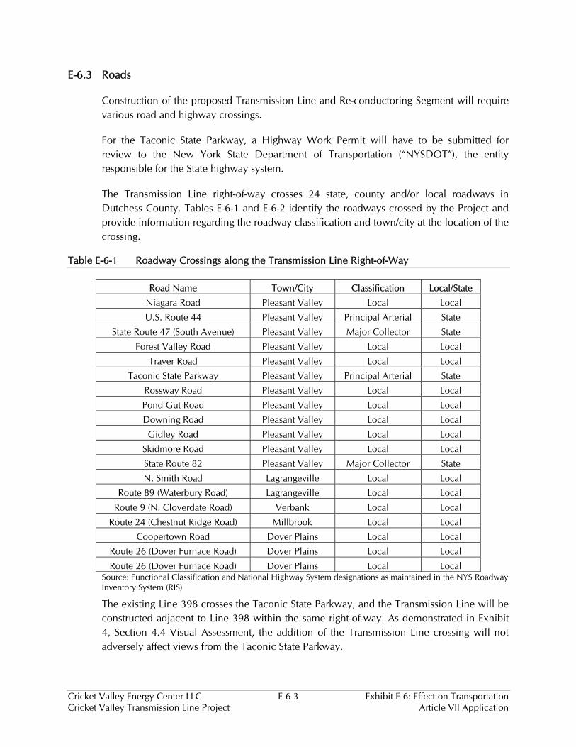
The Transmission Line right-of-way crosses 24 state, county and/or local roadways in Dutchess County. Tables E-6-1 and E-6-2 identify the roadways crossed by the Project and provide information regarding the roadway classification and town/city at the location of the crossing.
Table E-6-1 Roadway Crossings along the Transmission Line Right-of-Way
Road Name Town/City Classification Local/State
Niagara Road Pleasant Valley Local Local
U.S. Route 44 Pleasant Valley Principal Arterial State
State Route 47 (South Avenue) Pleasant Valley Major Collector State
Forest Valley Road Pleasant Valley Local Local
Traver Road Pleasant Valley Local Local
Taconic State Parkway Pleasant Valley Principal Arterial State
Rossway Road Pleasant Valley Local Local
Pond Gut Road Pleasant Valley Local Local
Downing Road Pleasant Valley Local Local
Gidley Road Pleasant Valley Local Local
Skidmore Road Pleasant Valley Local Local
State Route 82 Pleasant Valley Major Collector State
N. Smith Road Lagrangeville Local Local
Route 89 (Waterbury Road) Lagrangeville Local Local
Route 9 (N. Cloverdate Road) Verbank Local Local
Route 24 (Chestnut Ridge Road) Millbrook Local Local
Coopertown Road Dover Plains Local Local
Route 26 (Dover Furnace Road) Dover Plains Local Local
Route 26 (Dover Furnace Road) Dover Plains Local Local Source: Functional Classification and National Highway System designations as maintained in the NYS Roadway
Inventory System (RIS)
The existing Line 398 crosses the Taconic State Parkway, and the Transmission Line will be constructed adjacent to Line 398 within the same right-of-way. As demonstrated in Exhibit 4, Section 4.4 Visual Assessment, the addition of the Transmission Line crossing will not adversely affect views from the Taconic State Parkway.
Cricket Valley Energy Center LLC E-6-4 Exhibit E-6: Effect on Transportation Cricket Valley Transmission Line Project Article VII Application
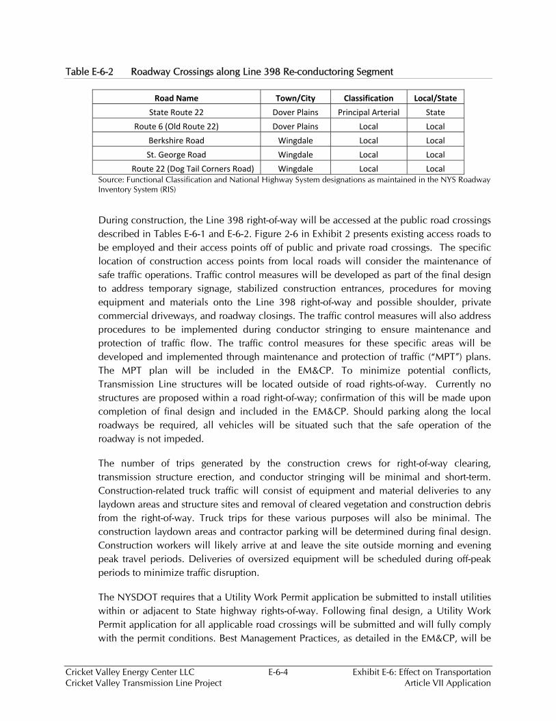
Table E-6-2 Roadway Crossings along Line 398 Re-conductoring Segment
Road Name Town/City Classification Local/State State Route 22 Dover Plains Principal Arterial State
Route 6 (Old Route 22) Dover Plains Local Local Berkshire Road Wingdale Local Local St. George Road Wingdale Local Local
Route 22 (Dog Tail Corners Road) Wingdale Local Local Source: Functional Classification and National Highway System designations as maintained in the NYS Roadway Inventory System (RIS)
During construction, the Line 398 right-of-way will be accessed at the public road crossings described in Tables E-6-1 and E-6-2. Figure 2-6 in Exhibit 2 presents existing access roads to be employed and their access points off of public and private road crossings. The specific location of construction access points from local roads will consider the maintenance of safe traffic operations. Traffic control measures will be developed as part of the final design to address temporary signage, stabilized construction entrances, procedures for moving equipment and materials onto the Line 398 right-of-way and possible shoulder, private commercial driveways, and roadway closings. The traffic control measures will also address procedures to be implemented during conductor stringing to ensure maintenance and protection of traffic flow. The traffic control measures for these specific areas will be developed and implemented through maintenance and protection of traffic (“MPT”) plans. The MPT plan will be included in the EM&CP. To minimize potential conflicts, Transmission Line structures will be located outside of road rights-of-way. Currently no structures are proposed within a road right-of-way; confirmation of this will be made upon completion of final design and included in the EM&CP. Should parking along the local roadways be required, all vehicles will be situated such that the safe operation of the roadway is not impeded.
The number of trips generated by the construction crews for right-of-way clearing, transmission structure erection, and conductor stringing will be minimal and short-term. Construction-related truck traffic will consist of equipment and material deliveries to any laydown areas and structure sites and removal of cleared vegetation and construction debris from the right-of-way. Truck trips for these various purposes will also be minimal. The construction laydown areas and contractor parking will be determined during final design. Construction workers will likely arrive at and leave the site outside morning and evening peak travel periods. Deliveries of oversized equipment will be scheduled during off-peak periods to minimize traffic disruption.
The NYSDOT requires that a Utility Work Permit application be submitted to install utilities within or adjacent to State highway rights-of-way. Following final design, a Utility Work Permit application for all applicable road crossings will be submitted and will fully comply with the permit conditions. Best Management Practices, as detailed in the EM&CP, will be

Cricket Valley Energy Center LLC E-6-5 Exhibit E-6: Effect on Transportation Cricket Valley Transmission Line Project Article VII Application
employed during construction activities to prevent the deposition of materials onto local roadways. Soil washed, dropped, spilled or tracked outside the limit of disturbance or onto public rights-of-way will be removed in a timely manner.
All work within state highway rights-of-way shall be designed and performed according to the traffic and safety standards and other substantive requirements, applicable design standards of the American Association of State Highway and Transportation Officials (“AASHTO”), the Manual of Uniform Traffic Control Devices (“MUTCD”), the Highway Design Manual, the Policy and Standards for Entrances to State Highways, the Requirements for the Design and the NYSDOT 2008 Standard Specifications.
E-6.4 Waterways
The Transmission Line and Re-conductoring Segment cross several small bodies of water but none are navigable waterways.
E-6.5 Pedestrian Traffic
Only a few small portions of the project are located in urban and suburban areas with development that provide opportunities for pedestrian traffic.
The corridor is currently used by Line 398 and the addition of the Transmission Line should not pose any additional issues related to pedestrian traffic. Measures will be taken during construction to dissuade pedestrians from entering the construction zones. The majority of the Line 398 right-of-way is routed through rural areas characterized by large plots of agricultural and forested land not commonly visited or accessed by the public and mostly owned by Con Edison. All Transmission Line design and construction will follow the National Electric Safety Code for clearances.