cs 540 computer networks ii sandy wang [email protected] 1
TRANSCRIPT


9. TRANSPORT LAYER – TCP/UDP
3
Topics
1. Overview2. LAN Switching3. IPv44. IPv65. Routing Protocols -- RIP, RIPng, OSPF6. Routing Protocols -- ISIS, BGP7. MPLS8. Midterm Exam9. Transport Layer -- TCP/UDP10. Access Control List (ACL)11. Congestion Control & Quality of Service (QoS)12. Application Layer Protocols13. Application Layer Protocols continue14. Others – Multicast, SDN15. Final Exam

4
Reference Books
• Cisco CCNA Routing and Switching ICND2 200-101 Official Cert Guide, Academic Edition by Wendel Odom -- July 10, 2013. ISBN-13: 978-1587144882
• The TCP/IP Guide: A Comprehensive, Illustrated Internet Protocols Reference by Charles M. Kozierok – October 1, 2005. ISBN-13: 978-1593270476
• Data and Computer Communications (10th Edition) (William Stallings Books on Computer and Data Communications) by Williams Stallings – September 23, 2013. ISBN-13: 978-0133506488
http://class.svuca.edu/~sandy/class/CS540/

5
TCP/IP protocol suite

6
Table 12.1 Well-known ports used by TCP

7
TCP Features FEATURES
• Numbering System • Flow Control• Error Control
Congestion Control

8
The bytes of data being transferred in each connection are numbered by TCP. The numbering starts with a randomly
generated number.

9
Suppose a TCP connection is transferring a file of 5000 bytes. The first byte is numbered 10001. What are the sequence numbers for each segment if data is sent in five segments, each carrying 1000 bytes?
Example
SolutionThe following shows the sequence number for each segment:
Segment 1 ➡ Sequence Number: 10,001 (range: 10,001 to 11,000)
Segment 2 ➡ Sequence Number: 11,001 (range: 11,001 to 12,000)
Segment 3 ➡ Sequence Number: 12,001 (range: 12,001 to 13,000)
Segment 4 ➡ Sequence Number: 13,001 (range: 13,001 to 14,000)
Segment 5 ➡ Sequence Number: 14,001 (range: 14,001 to 15,000)

10
The value in the sequence number field of a segment defines the number of the
first data byte containedin that segment.
11
The value of the acknowledgment field in a segment defines the number of the
next byte a party expects to receive.
The acknowledgment number is cumulative.
12
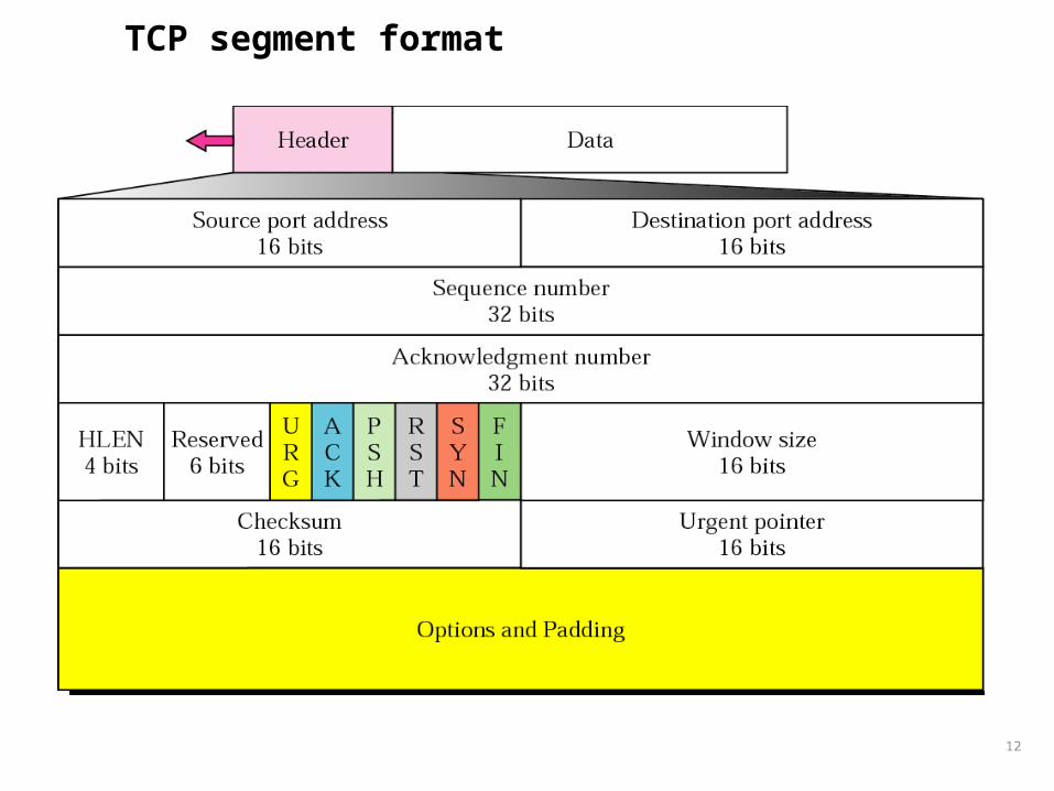
TCP segment format

13
Control field
14
I
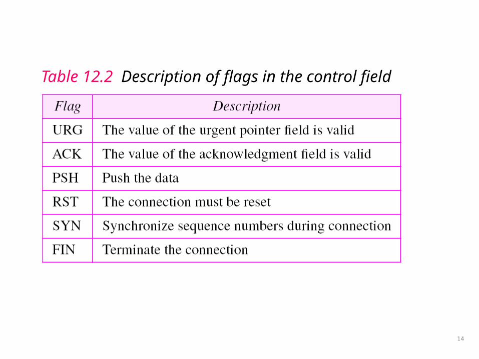
Table 12.2 Description of flags in the control field

15
Pseudoheader added to the TCP datagram
TCP Hdr + Data
16
The inclusion of the checksum in TCP is mandatory.
17
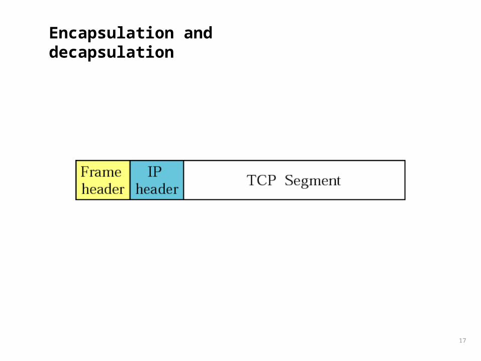
Encapsulation and decapsulation
18
A TCP CONNECTION
TCP is connection-oriented. A connection-oriented transport protocol establishes a virtual path between the source and destination. All of the segments belonging to a message are then sent over this virtual path. A connection-oriented transmission requires three phases: connection establishment, data transfer, and connection termination.
• Connection Establishment• Data Transfer• Connection Termination• Connection Reset
19
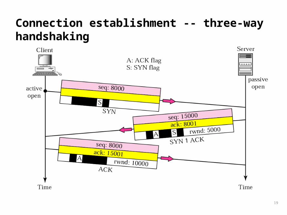
Connection establishment -- three-way handshaking

20
A SYN segment cannot carry data, but it consumes one sequence number.

21
A SYN + ACK segment cannot carry data, but does consume one
sequence number.

22
An ACK segment, if carrying no data, consumes no sequence number.

23
Data transfer

24
The FIN segment consumes one sequence number if it does not carry
data.
25
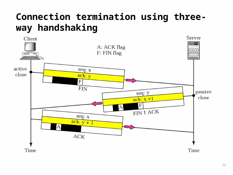
Connection termination using three-way handshaking
26
The FIN + ACK segment consumes one sequence number if it does not carry
data.
27
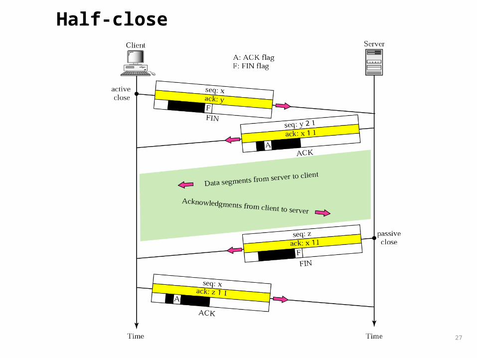
Half-close

28
States for TCP

29
State transition diagram

30
Common scenario

31
The common value for MSL is between 30 seconds and 1 minute.
MSL – Maximum Segment Lifetime

32
Three-way handshake

33
Simultaneous open

34
Simultaneous close

35
Denying a connection

36
Aborting a connection

Flow Contrl
• Flow control regulates the amount of data a source can send before receiving an acknowledgment from the destination. TCP defines a window that is imposed on the buffer of data delivered from the application program.
Sliding Window Protocol
Silly Window Syndrome
37

Sliding Window
38

39
A sliding window is used to make transmission more efficient as well as to
control the flow of data so that the destination does not become
overwhelmed with data.
TCP’s sliding windows are byte oriented.
40
What is the value of the receiver window (rwnd) for host A if the receiver, host B, has a buffer size of 5,000 bytes and 1,000 bytes of received and unprocessed data?
Example
SolutionThe value of rwnd = 5,000 − 1,000 = 4,000. Host B can receive only 4,000 bytes of data before overflowing its buffer. Host B advertises this value in its next segment to A.

41
What is the size of the window for host A if the value of rwnd is 3,000 bytes and the value of cwnd is 3,500 bytes?
Example 4
SolutionThe size of the window is the smaller of rwnd and cwnd, which is 3,000 bytes.

42
The sender has sent bytes up to 202. We assume that cwnd is 20 (in reality this value is thousands of bytes). The receiver has sent an acknowledgment number of 200 with an rwnd of 9 bytes (in reality this value is thousands of bytes). The size of the sender window is the minimum of rwnd and cwnd or 9 bytes. Bytes 200 to 202 are sent, but not acknowledged. Bytes 203 to 208 can be sent without worrying about acknowledgment. Bytes 209 and above cannot be sent.
Example
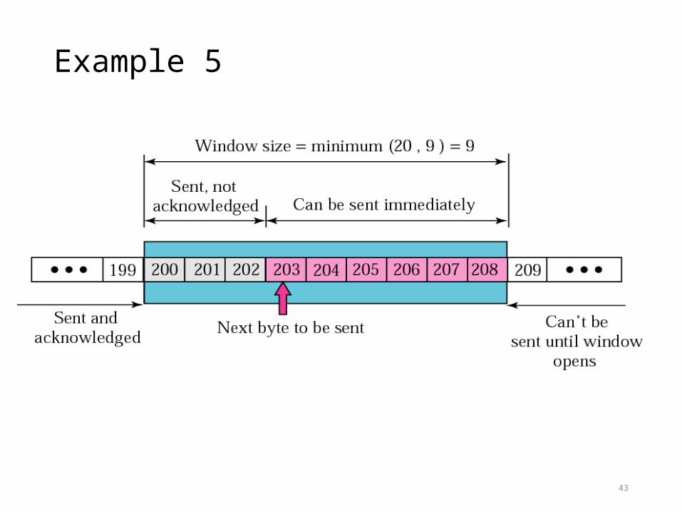
Example 5
43

44
In Figure 12.21 the server receives a packet with an acknowledgment value of 202 and an rwnd of 9. The host has already sent bytes 203, 204, and 205. The value of cwnd is still 20. Show the new window.
Example
SolutionFigure 12.22 shows the new window. Note that this is a case in which the window closes from the left and opens from the right by an equal number of bytes; the size of the window has not been changed. The acknowledgment value, 202, declares that bytes 200 and 201 have been received and the sender needs not worry about them; the window can slide over them.

Example 6
45

46
In Figure 12.22 the sender receives a packet with an acknowledgment value of 206 and an rwnd of 12. The host has not sent any new bytes. The value of cwnd is still 20. Show the new window.
Example
SolutionThe value of rwnd is less than cwnd, so the size of the window is 12. Figure 12.23 shows the new window. Note that the window has been opened from the right by 7 and closed from the left by 4; the size of the window has increased.

47

48
In Figure 12.23 the host receives a packet with an acknowledgment value of 210 and an rwnd of 5. The host has sent bytes 206, 207, 208, and 209. The value of cwnd is still 20. Show the new window.
Example
SolutionThe value of rwnd is less than cwnd, so the size of the window is 5. Figure 12.24 shows the situation. Note that this is a case not allowed by most implementations. Although the sender has not sent bytes 215 to 217, the receiver does not know this.

49
50
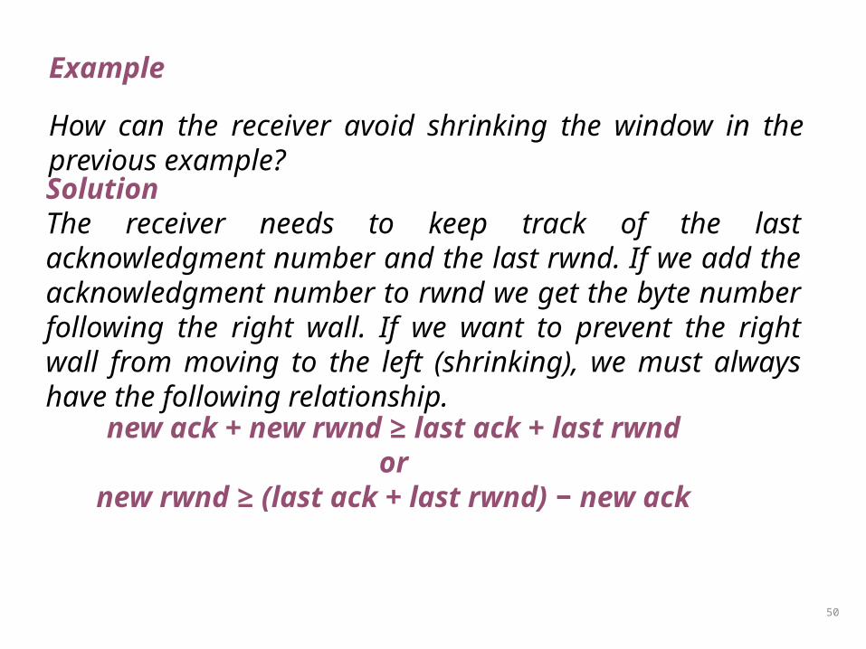
How can the receiver avoid shrinking the window in the previous example?
Example
SolutionThe receiver needs to keep track of the last acknowledgment number and the last rwnd. If we add the acknowledgment number to rwnd we get the byte number following the right wall. If we want to prevent the right wall from moving to the left (shrinking), we must always have the following relationship.
new ack + new rwnd ≥ last ack + last rwndor
new rwnd ≥ (last ack + last rwnd) − new ack

51
To avoid shrinking the sender window, the receiver must wait until more space
is available in its buffer.
52
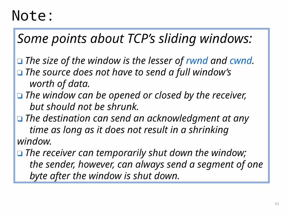
Some points about TCP’s sliding windows:
❏ The size of the window is the lesser of rwnd and cwnd.❏ The source does not have to send a full window’s worth of data.❏ The window can be opened or closed by the receiver, but should not be shrunk.❏ The destination can send an acknowledgment at any time as long as it does not result in a shrinking window.❏ The receiver can temporarily shut down the window; the sender, however, can always send a segment of one byte after the window is shut down.
Note:

53
Error Control
TCP provides reliability using error control, which detects corrupted, lost, out-of-order, and duplicated segments. Error control in TCP is achieved through the use of the checksum, acknowledgment, and time-out.
• Checksum• Acknowledgment• Acknowledgment Type• Retransmission• Out-of-Order Segments • Some Scenarios

54
ACK segments do not consume sequence numbers and are not
acknowledged.

55
In modern implementations, a retransmission occurs if the
retransmission timer expires or three duplicate ACK segments have arrived.

56
No retransmission timer is set for an ACK segment.
57
Data may arrive out of order and be temporarily stored by the receiving TCP, but
TCP guarantees that no out-of-order segment is delivered to the process.

Normal Operation
58

Lost Segment
59

60
The receiver TCP delivers only ordered data to the process.

Fast Retransmission
61

Lost Acknowledgement
62

Lost acknowledgment corrected by resending a segment
63

64
Lost acknowledgments may create deadlock if they are not properly
handled.

Congestion Control
65
Congestion control refers to the mechanisms and techniques to keep the load below the capacity.
• Network Performance• Congestion Control Mechanisms• Congestion Control in TCP

Slow start, exponential increase
66

67
In the slow start algorithm, the size of the congestion window increases exponentially until it reaches a
threshold.

Congestion avoidance, additive increase
68

69
In the congestion avoidance algorithm the size of the congestion window
increases additively until congestion is detected.
70
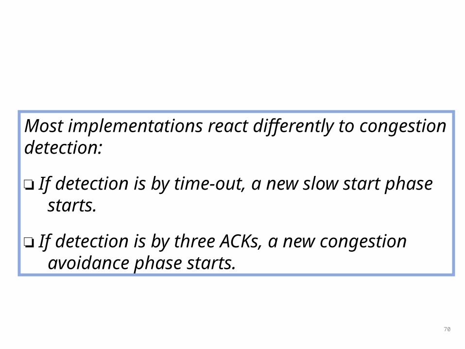
Most implementations react differently to congestion detection:
❏ If detection is by time-out, a new slow start phase starts.
❏ If detection is by three ACKs, a new congestion avoidance phase starts.

TCP congestion policy summary
71

Congestion example
72
TCP Timers
73
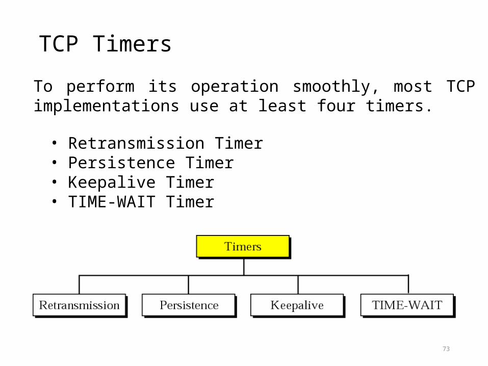
To perform its operation smoothly, most TCP implementations use at least four timers.
• Retransmission Timer• Persistence Timer• Keepalive Timer• TIME-WAIT Timer

74
TCP Timers
• TCP maintains four (4) timers for each connection:• Retransmission Timer:
• The timer is started during a transmission. A timeout causes a retransmission
• Persist Timer• Ensures that window size information is transmitted even if no
data is transmitted• Keepalive Timer
• Detects crashes on the other end of the connection • 2MSL Timer
• Measures the time that a connection has been in the TIME_WAIT state
• MSL – Maximum Segment Lifetime

75
Retransmission Timer (RT Timer)
Setting the RT timer• When a segment is sent and RT timer is not running, start RT timer with
RTO value• Turn off RT timer, when all data is acknowledged• When an ACK is received for new data, reset the RT timer to RTO value
RT timer expires• Retransmit the earliest segment that has not been acknowledged• Double value of RTO (see Karn’s rule)• Start the RT timer with RTO value
76
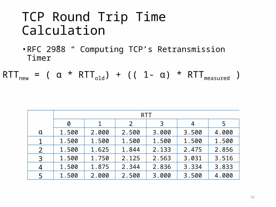
TCP Round Trip Time Calculation
• RFC 2988 “ Computing TCP’s Retransmission Timer”
RTTnew = ( α * RTTold) + (( 1- α) * RTTmeasured )
α
RTT0 1 2 3 4 5
1.500 2.000 2.500 3.000 3.500 4.0001 1.500 1.500 1.500 1.500 1.500 1.5002 1.500 1.625 1.844 2.133 2.475 2.8563 1.500 1.750 2.125 2.563 3.031 3.5164 1.500 1.875 2.344 2.836 3.334 3.8335 1.500 2.000 2.500 3.000 3.500 4.000
77
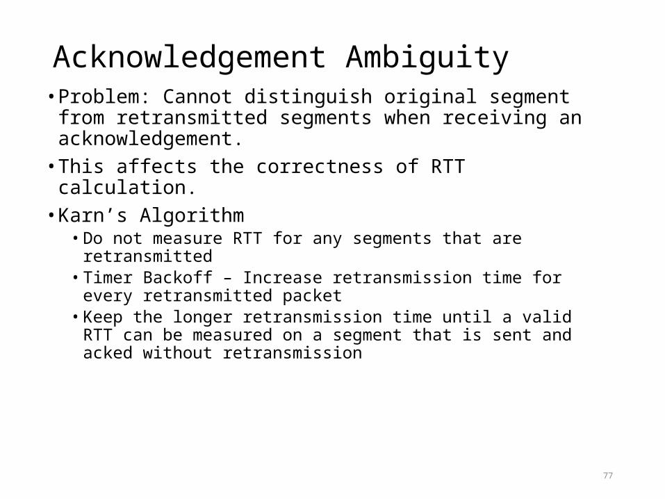
Acknowledgement Ambiguity• Problem: Cannot distinguish original segment from retransmitted
segments when receiving an acknowledgement. • This affects the correctness of RTT calculation.• Karn’s Algorithm
• Do not measure RTT for any segments that are retransmitted• Timer Backoff – Increase retransmission time for every retransmitted packet• Keep the longer retransmission time until a valid RTT can be measured on a
segment that is sent and acked without retransmission

78
TCP Persist Timer
• Assume the window size goes down to zero and the ACK that opens the window gets lost
3K
2K SeqNo=0
ReceiverBuffer
0 4K
2K
AckNo=2048 Win=2048
ACK islost
2K SeqNo=20484K
AckNo=4096 Win=0
AckNo=4096 Win=1024
Sender blocked
If ACK (see figure) is lost, both sides are blocked.
Persist Timer:Forces that the sender
periodically queries the receiver about its window size (window probes)

79
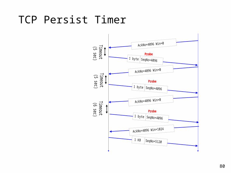
TCP Persist Timer
• The persist timer is started by the sender when the sliding window is zero
Persist timer uses exponential backoff (initial value is 1.5 seconds) rounded to the range [5 sec, 60sec]So the time interval between timeouts are at:
5, 5, 6, 12, 24, 48, 60, 60, ...The window probe packet contains one byte of data (TCP can do this even if the window size is zero)
80
TCP Persist Timer
Timeout
(5 sec)
Timeout
(5 sec)Tim
eout(6 sec)
Probe
Probe
Probe

81
TCP Keepalive Timer
• When a TCP connection has been idle for a long time (1 min – 2 hours), a Keepalive timer reminds a station to check if the other side is still there.
• A segment wihtout data is sent if the connection has been idle for 2 hours
• Assume a probe has been sent from A to B:(1) B is up and running: B responds with an ACK(2) B has crashed and is down: A will send 10 more probes, each 75 seconds apart. If A does not get a response, it will close the connection (3) B has rebooted: B will send a RST segment(4) B is up, but unreachable: Looks to A the same as (2)

TCP Options
82
The TCP header can have up to 40 bytes of optional information.

End-of-option option
83
84
EOP can be used only once.

No-operation option
85
An option may begin on any byte boundary. The TCP header must be padded with zeros to make the header length a multiple of 32 bits.

86
NOP can be used more than once.

Maximum-segment-size option
87

88
The value of MSS is determined during connection establishment and does not
change during the connection.

Window-scale-factor option
89
90
The value of the window scale factor can be determined only during
connection establishment; it does not change during the connection.
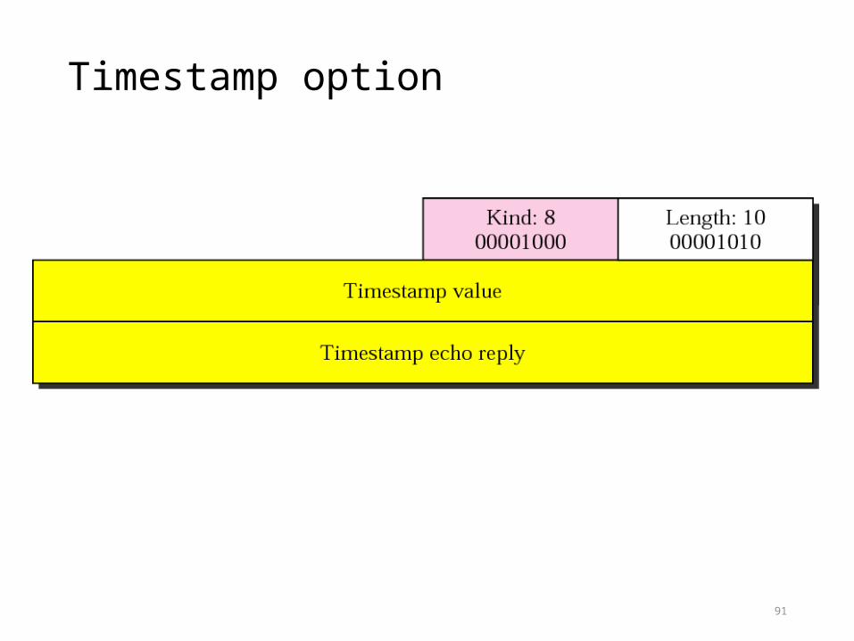
Timestamp option
91

92
One application of the timestamp option is the calculation of round trip
time (RTT).

Example 12
93

94
The timestamp option can also be used for PAWS – Protection Against Wrapping Sequence Number

SACK
95

96
Let us see how the SACK option is used to list out-of-order blocks. In Figure 12.48 an end has received five segments of data.
Example 13
The first and second segments are in consecutive order. An accumulative acknowledgment can be sent to report the reception of these two segments. Segments 3, 4, and 5, however, are out of order with a gap between the second and third and a gap between the fourth and the fifth. An ACK and a SACK together can easily clear the situation for the sender. The value of ACK is2001, which means that the sender need not worry about bytes 1 to 2000. The SACK has two blocks. The first block announces that bytes 4001 to 6000 have arrived out of order. The second block shows that bytes 8001 to 9000 have also arrived out of order. This means that bytes 2001 to 4000 and bytes 6001 to 8000 are lost or discarded. The sender can resend only these bytes.

Example 13
97

98
The example in Figure 12.49 shows how a duplicate segment can be detected with a combination of ACK and SACK. In this case, we have some out-of-order segments (in one block) and one duplicate segment. To show both out-of-order and duplicate data, SACK uses the first block, in this case, to show the duplicate data and other blocks to show out-of-order data. Note that only the first block can be used for duplicate data. The natural question is how the sender, when it receives these ACK and SACK values knows that the first block is for duplicate data (compare this example with the previous example). The answer is that the bytes in the first block are already acknowledged in the ACK field; therefore, this block must be a duplicate.
Example 14

Example 14
99
100
The example in Figure 12.50 shows what happens if one of the segments in the out-of-order section is also duplicated. In this example, one of the segments (4001:5000) is duplicated. The SACK option announces this duplicate data first and then the out-of-order block. This time, however, the duplicated block is not yet acknowledged by ACK, but because it is part of the out-of-order block (4001:5000 is part of 4001:6000), it is understood by the sender that it defines the duplicate data.
Example 15

Example 15
101

Position of UDP in the TCP/IP protocol suite
102

PROCESS-TO-PROCESS COMMUNICATIOn
103
Before we examine UDP, we must first understand host-to-host communication and process-to-process communication and the difference between them.
• Port Numbers• Socket Addresses
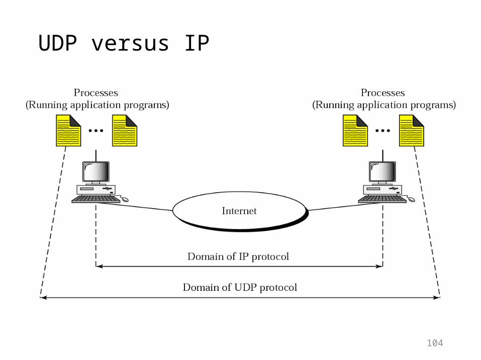
UDP versus IP
104

Port numbers
105

IP addresses versus port numbers
106

ICANN ranges
107

108
The well-known port numbers are less than 1024.

109
Table 11.1 Well-known ports used with UDP
110
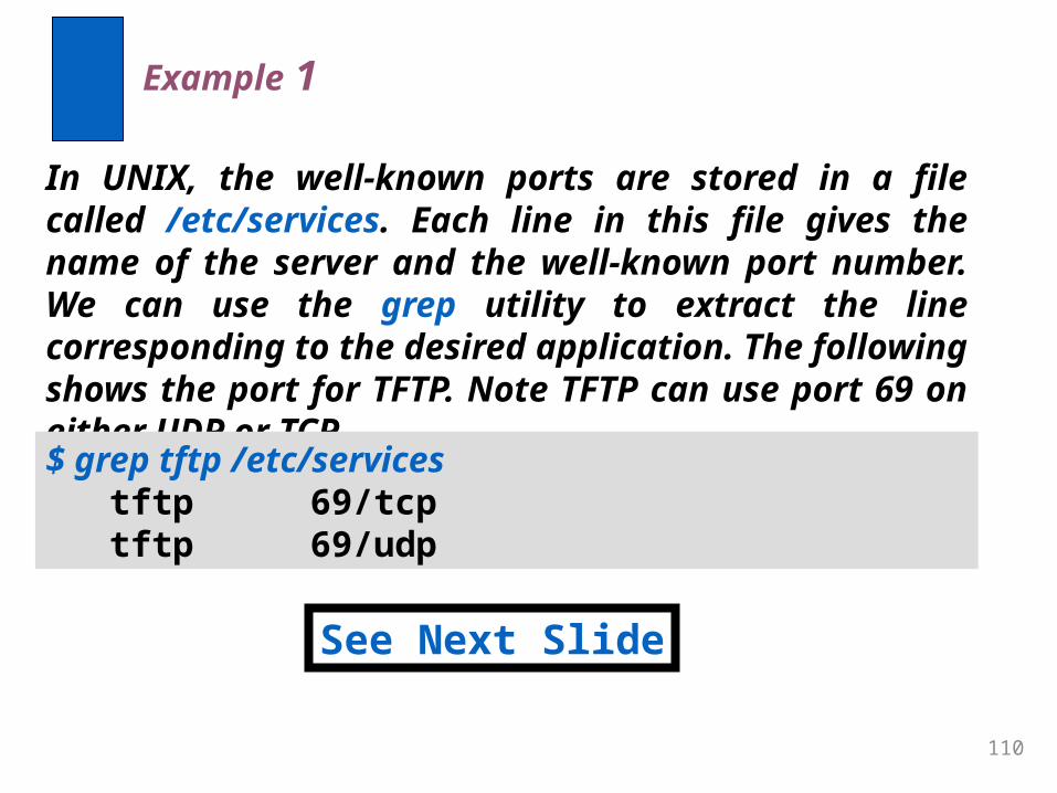
In UNIX, the well-known ports are stored in a file called /etc/services. Each line in this file gives the name of the server and the well-known port number. We can use the grep utility to extract the line corresponding to the desired application. The following shows the port for TFTP. Note TFTP can use port 69 on either UDP or TCP.
Example 1
See Next Slide
$ grep tftp /etc/services tftp 69/tcp tftp 69/udp

111
SNMP uses two port numbers (161 and 162), each for a different purpose, as we will see in Chapter 21.
Example 1 (Continued)
$ grep snmp /etc/services snmp 161/tcp #Simple Net Mgmt Proto snmp 161/udp #Simple Net Mgmt Proto snmptrap 162/udp #Traps for SNMP

Socket address
112

User datagram format
113
UDP packets are called user datagrams and have a fixed-size header of 8 bytes.

114
UDP length = IP length − IP header’s length

UDP Checksum
115
UDP checksum calculation is different from the one for IP and ICMP. Here the checksum includes three sections: a pseudoheader, the UDP header, and the data coming from the application layer.
• Checksum Calculation at Sender• Checksum Calculation at Receiver• Optional Use of the Checksum

Pseudoheader for checksum calculation
116

Checksum calculation of a simple UDP user datagram
117

UDP OPERATION
118
• Connectionless Services• Flow and Error Control• Encapsulation and Decapsulation• Queuing• Multiplexing and Demultiplexing

Encapsulation and decapsulation
119

Queues in UDP
120

Multiplexing and demultiplexing
121