customer satisfaction takes priority: first pipe for
TRANSCRIPT

P E O P L E | M A R K E T S | M A C H I N E S
bulletinT h e S i e m p e l k a m p M a g a z i n e
I s s u e 0 1 | 2 0 1 3
Customer satisfaction takes priority: First pipe for TenarisConfab, Brazil “Monte Carlo”: New 3-D activation process for decommissioning A piece of Siempelkamp in every house: Cast components for the building materials industry Frati celebrates First board of avant-garde ContiRoll®: On-site visit – Interview with Luigi Frati

pit ute digna facillam ing
Magna corModipit ute digna facillam
Autor: In ulla feugait, quat num v
In ulla feugait, quat num vel ulpute faci blandrer ad tat ea commy nulputat il dolore dolestrud ex elent velit lummy num quis nulput nostrud dolore ver irit nim adipit vendrerit venit wisl ing el utat, sissim diat.
diam veliquat, sequi tat.Mincipit niam dolor ing et wisi eum non utatum dolesse te eu-guer Adio conse tatin velisi tie delit dolor iure miniam, con enis-sequis atio dolent amet veraessent at.Cillandre tie core con hent ver iure mincip ex eliquis nos eugiam, cor alit lore tie molorem dolorpe raessit lorperos eugait aliquis issenisim quis am, conse magna feugait in henisi.Giat nim amet la facin ulla feuis dipis nos er augiam, sequipit at at. Lis ex eumsand iamcon eummy nim delit verillu mmolor sed tat lam zzrillute con vel ilit amconum nim inim veliquat ullupta tumsandre magna adignibh endre magna consed tie dolortis nul-lum dolor ilit augiatueril doluptatum vendrerilit dio consequisi.Alit nim in velent aut ad esequisim quipsum nonsenim quisi blan-dio do consecte tis alis exero erosto essectetue faccum volenim doluptat wisi.
unt euisi te molobor susto et nisim volore tat.
Lendit aliquat. Ut vel in heniat, consecte feum accummodipis do-lessent lortis duiscidunt incing euisim irit nullutat. At nulputat. Ut amcoreet wis nummolorero deliquisim num elismod et, sit lum diatum ilit vel ing eugiam, conse delendre vulla commy num alit ero ea commolore dolore eugait at la facipsu msandiam illaore rcincidunt prat, vel eum dolor sustrud modolobor adiat, sim enibh eugiam enis etue tis amcommolore tat. Duis dolortio coreet wismolore del ipis nissi.Unt aute magna augiam dit ullum doluptating estisi.Sit ulla feumsan ulla feuguer aesequat lum iureet lorperostrud minis er suscidui eraessit loreet, commolo borperit iriliqu ismo-lum sandrem volore dip eugait augueros augue magnissim quam velit irillaoreet wis nulla adip essit lore tisl ulputem deliquatio dui erostie magna feuip erit la faccumsan el ut lumsan utpat.Deliquisisi. Eros elisi blan henis eugue consed modolore feuis nis-modolorem ilit volessi tat. Ut exercidunt vullam incincilis nim vo-
Adio conse tatin velisi tie delit dolor iure miniam, con enissequis atio dolent amet veraessent at.
Cillandre tie core con hent ver iure mincip ex eliquis nos eugiam, cor alit lore tie molorem dolorpe raessit lorperos eugait aliquis issenisim quis am, conse magna feugait in henisi.Giat nim amet la facin ulla feuis dipis nos er augiam, sequipit at at. Lis ex eumsand iamcon eummy nim delit verillu mmolor sed tat lam zzrillute con vel ilit amconum nim inim veliquat ullupta tumsandre magna adignibh endre magna consed tie dolortis nul-lum dolor ilit augiatueril doluptatum vendrerilit dio consequisi.Alit nim in velent aut ad esequisim quipsum nonsenim quisi blan-dio do consecte tis alis exero erosto essectetue faccum volenim doluptat wisi.Obortinim quipisi. Ed er iriustie exeros alissit nosto core volobore magniamet, quipit nibh essi bla facilit la facidunt euisi te molobor susto et nisim volore tat.Lendit aliquat. Ut vel in heniat, consecte feum accummodipis do-lessent lortis duiscidunt incing euisim irit nullutat. At nulputat. Ut amcoreet wis nummolorero deliquisim num elismod et, sit lum diatum ilit vel ing eugiam, conse delendre vulla commy num alit ero ea commolore dolore eugait at la facipsu msandiam illaore rcincidunt prat, vel eum dolor sustrud modolobor adiat, sim enibh eugiam enis etue tis amcommolore tat. Duis dolortio coreet wismolore del ipis nissi.Unt aute magna augiam dit ullum doluptating estisi.Sit ulla feumsan ulla feuguer aesequat lum iureet lorperostrud minis er suscidui eraessit loreet, commolo borperit iriliqu ismo-lum sandrem volore dip eugait augueros augue magnissim quam velit irillaoreet wis nulla adip essit lore tisl ulputem deliquatio dui erostie magna feuip erit la faccumsan el ut lumsan utpat.Deliquisisi. Eros elisi blan henis eugue consed modolore feuis nis-modolorem ilit volessi tat. Ut exercidunt vullam incincilis nim vo-lobor ip et ut ametuer cillummy nullaor eriure del ut vel delenim
siempelkamp | MASChinEn- UnD AnLAGEnbAU
diam veliquat, sequi tat.Mincipit niam dolor ing et wisi eum non utatum dolesse te eu-guer Adio conse tatin velisi tie delit dolor iure miniam, con enis-sequis atio dolent amet veraessent at.Cillandre tie core con hent ver iure mincip ex eliquis nos eugiam, cor alit lore tie molorem dolorpe raessit lorperos eugait aliquis issenisim quis am, conse magna feugait in henisi.Giat nim amet la facin ulla feuis dipis nos er augiam, sequipit at at. Lis ex eumsand iamcon eummy nim delit verillu mmolor sed tat lam zzrillute con vel ilit amconum nim inim veliquat ullupta tumsandre magna adignibh endre magna consed tie dolortis nul-lum dolor ilit augiatueril doluptatum vendrerilit dio consequisi.Alit nim in velent aut ad esequisim quipsum nonsenim quisi blan-dio do consecte tis alis exero erosto essectetue faccum volenim doluptat wisi.
unt euisi te molobor susto et nisim volore tat.
Lendit aliquat. Ut vel in heniat, consecte feum accummodipis do-lessent lortis duiscidunt incing euisim irit nullutat. At nulputat. Ut amcoreet wis nummolorero deliquisim num elismod et, sit lum diatum ilit vel ing eugiam, conse delendre vulla commy num alit ero ea commolore dolore eugait at la facipsu msandiam illaore rcincidunt prat, vel eum dolor sustrud modolobor adiat, sim enibh eugiam enis etue tis amcommolore tat. Duis dolortio coreet wismolore del ipis nissi.Unt aute magna augiam dit ullum doluptating estisi.Sit ulla feumsan ulla feuguer aesequat lum iureet lorperostrud minis er suscidui eraessit loreet, commolo borperit iriliqu ismo-lum sandrem volore dip eugait augueros augue magnissim quam velit irillaoreet wis nulla adip essit lore tisl ulputem deliquatio dui erostie magna feuip erit la faccumsan el ut lumsan utpat.Deliquisisi. Eros elisi blan henis eugue consed modolore feuis nis-modolorem ilit volessi tat. Ut exercidunt vullam in
Adio conse tatin velisi tie delit dolor iure miniam, con enissequis atio dolent amet veraessent at.
Cillandre tie core con hent ver iure mincip ex eliquis nos eugiam, cor alit lore tie molorem dolorpe raessit lorperos eugait aliquis issenisim quis am, conse magna feugait in henisi.Giat nim amet la facin ulla feuis dipis nos er augiam, sequipit at at. Lis ex eumsand iamcon eummy nim delit verillu mmolor sed tat lam zzrillute con vel ilit amconum nim inim veliquat ullupta tumsandre magna adignibh endre magna consed tie dolortis nul-lum dolor ilit augiatueril doluptatum vendrerilit dio consequisi.Alit nim in velent aut ad esequisim quipsum nonsenim quisi blan-dio do consecte tis alis exero erosto essectetue faccum volenim doluptat wisi.Obortinim quipisi. Ed er iriustie exeros alissit nosto core volobore magniamet, quipit nibh essi bla facilit la facidunt euisi te molobor susto et nisim volore tat.Lendit aliquat. Ut vel in heniat, consecte feum accummodipis do-lessent lortis duiscidunt incing euisim irit nullutat. At nulputat. Ut amcoreet wis nummolorero deliquisim num elismod et, sit lum diatum ilit vel ing eugiam, conse delendre vulla commy num alit ero ea commolore dolore eugait at la facipsu msandiam illaore rcincidunt prat, vel eum dolor sustrud modolobor adiat, sim enibh eugiam enis etue tis amcommolore tat. Duis dolortio coreet wismolore del ipis nissi.Unt aute magna augiam dit ullum doluptating estisi.Sit ulla feumsan ulla feuguer aesequat lum iureet lorperostrud minis er suscidui eraessit loreet, commolo borperit iriliqu ismo-lum sandrem volore dip eugait augueros augue magnissim quam velit irillaoreet wis nulla adip essit lore tisl ulputem deliquatio dui erostie magna feuip erit la faccumsan el ut lumsan utpat.Deliquisisi. Eros elisi blan henis eugue consed modolore feuis nis-modolorem ilit volessi tat. Ut exercidunt vullam incincilis nim vo-lobor ip et ut ametuer cillummy nullaor eriure del ut vel delenim
pit ute digna facillam ing
Magna corModipit ute digna
Autor: In ulla feugait, quat num v
In ulla feugait, quat num vel ulpute faci blandrer ad tat ea commy nulputat il dolore dolestrud ex elent velit lummy num quis nulput nostrud dolore ver irit nim adipit vendrerit venit wisl ing el utat, sissim diat.
Cover: The U- and O-forming presses, Tenaris, Brazil SieMpelkAMp | Contents
ImprintPublisher G. siempelkamp GmbH & Co. KG, Marketing/Communication Department, siempelkampstr. 75, 47803 Krefeld (Germany)
executive editor (officer responsible for compliance with German press law) Ralf Griesche text Dr. silke Hahn and Inga Bambitsch
typesetting and Layout ve&K Werbeagentur GmbH & Co. KG Printing WAZ-Druck GmbH & Co. KG, Duisburg
this publication is published in German and english. Reprints, in whole or in part and including illustrations, require the Publisher’s permission,
which in most cases is gladly given. Visit siempelkamp on the Internet: www.siempelkamp.com
Ralf Griesche
04 Frati celebrates First board of avant-garde ContiRoll®
on-site visit – Interview with Luigi Frati
Heinz Classen
10 The first Generation 8 ContiRoll® with new pressure distribution technology in Russia Reconstruction and modernization of a Russian particleboard line in record time
Timo Amels
14 ATR goes online with new web shop Measurement and control electronics via mouse click
Satish Gupta
16 Bending and dishing press for sound production security First and second edition for BHeL
Steffen Aumüller
20 Exciting innovation with technological advantage Conveyor belt plants made by siempelkamp
Costa Kluge, Siegfried Buecher
22 Customer satisfaction takes priority First pipe for tenarisConfab, Brazil
Dr. Michael Schöler
28 Siempelkamp press technology for the aerospace industry Aeronautical research program inspires high-precision fiber composite materials
Derek Clark
34 Strothmann transfer system for Volkswagen on the right track thanks to siempelkamp‘s expertise in composite manufacturing
Dirk Bender
38 “Monte Carlo” provides an innovation push new 3-D activation process for decommissioning
Ute de Vries
44 Siempelkamp Krantechnik in permanent service for the MEYER WERFT shipyard High-level (wing) spans!
Antonius Lanfermann / Marc Wlcek
50 Bolt cleaning device used for the first time in the French town of Gravelines Prototype of siempelkamp tensioning systems goes into mass production
Berthold Racky / Hermann-Josef Igelmund
54 NIS Technical Center: process qualification during decommissioning Plasma hot wire cutting
Helmut Rieck / Mathias Weil60 A piece of Siempelkamp in every house Cast components for the building materials industry

pit ute digna facillam ing
Magna corModipit ute digna facillampit ute digna facillam ing
Magna corModipit ute digna
32SieMpelkAMp | eDItoRIAL
Dear Readers:
Dr.-Ing. Hans W. Fechner
Chairman of the Executive Board
G. Siempelkamp GmbH & Co. KG
do you possess the DnA of an innovator? Professors from the Harvard Business school have researched the criteria necessary to develop strong ideas and become a progressive thinker of an industry. Four characteristics are decisive in terms of determining whether and to what degree companies and managers are innovative:
questioning, observing, experimenting and networking
Innovators question existing concepts to maintain benchmark achievements at a high level. Regardless whether we take our ContiRoll® Generation 8, our new cable tensioning system for conveyor belt plants or the customized systems of siempelkamp Crane technology for special shipbuilding: our teams always design successful models a decisive step further.
“observation” is a central siempelkamp concern. Here, the objective is to quickly and in a targeted way determine market and customer requirements. the demand for high energy efficiency, economic storage and extremely high throughputs brought us forward regarding the U-forming and o-forming press projects for tenaris. siempelkamp Foundry, on the other hand, focuses on the customer-specific development and optimizing of cast components.
experimenting – a strong point of our Research and Development department. A joint project with Airbus to develop a modern production process for the manufacturing of thermoplastic box structures demonstrates our strengths. Furthermore, a new 3-D activation process of our nuclear technology unit opens up significant savings in the dismantling of nuclear power plants.
Last but not least, networking is a central component of our innovative nature. An example of the perfect co-operation between all our machinery and plant engineering companies is the osB plant for Kalevala which we provided completely from one source.
the same goes for the networking of our three business units: this time it is the Machine and Plant engineering business unit which machines castings manufactured by siempelkamp Foundry in order to save the customer time and logistical expenses. next time our nuclear technology business unit and its markets will benefit from the casting competence of the foundry.
Let us together continue to use and expand these qualities to your benefit and to stay avant-garde in our markets, as one interview partner in this Bulletin sums up very well.
With best regards from Krefeld
Dr.-Ing. Hans W. Fechner

New ContiRoll® Generation 8 – manufacturing with higher flexibility:
Frati celebrates the production of the First Board with avant-garde ContiRoll® Not including the latest order, the Italian wood-based materials manufacturer Frati Luigi S.P.A. has ordered seven presses
from Siempelkamp including six short-cycle presses and one ContiRoll® press over the years. The current eighth project
sets a new milestone: in February 2013 Frati celebrated the production of the First Board on the most modern ContiRoll®
in the world – the Generation 8!
the location of the new press is Bicinicco, a commune in the Italian province of Udine. Here, the Frati subsidiary Bipan s.P.A. is specializing in MDF production. In May 2011 Frati signed the contract, in July 2012 construction started and at the end of February 2013 the Generation 8 ContiRoll® press produced its First Board.
ContiRoll® with mat cross-cut saw in the foreground
by Ralf Griesche
SieMpelkAMp | MACHIneRy AnD PLAnts
54
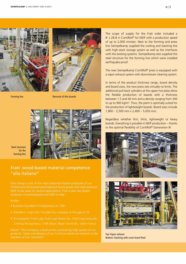
the scope of supply for the Frati order included a 8’ x 28.8 m ContiRoll® for MDF with a production speed of up to 2,000 mm/sec. next to the forming and press line siempelkamp supplied the cooling and stacking line with high-stack storage system as well as the interfaces with the existing systems. siempelkamp also supplied the steel structure for the forming line which were installed earthquake-proof.
the new siempelkamp ContiRoll® press is equipped with a vapor exhaust system with downstream cleaning system.
In terms of the product thickness range, board density and board sizes, the new press sets virtually no limits. the additional pull-back cylinders at the upper hot plate allow the flexible production of boards with a thickness between 1.5 and 40 mm and a density ranging from 340 to up to 900 kg/m3. thus, the plant is optimally suited for the production of lightweight boards. Board sizes include 1,860 – 2,500 mm x 2,400 – 5,650 mm.
Regardless whether thin, thick, lightweight or heavy boards: everything is possible in MDF production – thanks to the optimal flexibility of ContiRoll® Generation 8!
Top: Vapor exhaustBottom: Stacking with cover board feed
Forming line Removal of thin boards
Steel structure for the
forming line
Frati: wood-based material competence “alla italiano” Frati Group is one of the most important Italian producers of un-finished and laminated particleboard faced panels and high-pressure MDF to be used for several applications. Frati is also the largest producer of particleboard and MDF in Italy.
Profile:
• Business founded in Pomponesco in 1961
• President: Luigi Frati, founded his company at the age of 26
• 8 companies: Frati Luigi, Frati Luigi Pantec div., Frati Luigi Living div.,
Chimica Pomponesco, CMP, Bipan, Bipan Astrid div., Valori Franco
Motto: “our company is built on the consistently high quality of our products. styles and designs of our furniture panels are tailored to the requests of our customers.”
SieMpelkAMp | MACHIneRy AnD PLAnts

Special features for a complex range of requirements
the complex requirements for this order cannot be met without special equipment. that’s why siempelkamp equipped the forming line with a heavy-duty pre-press which applies pressures of 1,200 n/cm². the innovative concept of our Generation 8 also includes a mat cross-cut saw which is part of the forming line. the benefit: During production interruptions, which require a mat reject, this saw makes a cut to produce a homogeneous and precise leading edge of the mat. When the mat is re-fed into the press, a defined high speed transfer is guaranteed.
the order also included a compactor system. the advantage for the plant operator: At high board densities and speeds, optimal and uniform feeding of the mat into the press is possible! the compactor compresses the mat under the final board thickness and thus protects the steel belt from possible glue clots. thus, very thin boards can be safely produced.
our ecocalibrator was also part of the order: this innovative pressure distribution plate concept is an important component of the ContiRoll® Generation 8 press operating at Frati. the concept in cludes two components: 1.) pressure distribution plates that are
arranged over the entire length of the press, 2.) an addi tion al row of cylinders for the 8’ wide line which distributes the pressure virtually isobaric over the entire area.
this concept provides the customer with many advantages: the improved pressure distribution inside the press results in significant material savings. the use of pressure distribution plates results in improved thickness tolerances which in turn leads to lower resin consumption. the wood consumption is also less due to these reasons. the arrangement of the differential cylinders across the width of the press frames results in an optimum density profile at the board edges. this results in cost savings for edge trimming.
An important milestone towards full operational capacity has been reached with the production of the First Board in Bicinicco: the forecasted capacity for 3 mm boards is 700 m³ per day and 230,000 m³ per year. this ambitious concept which siempelkamp introduced at Ligna 2011 is now reality in Italy.
the press order represents the eighth joint project between Frati and siempelkamp: In the mid 1990s the Italian Group ordered a ContiRoll® press for particleboard. Furthermore, Frati ordered a total of six short-cycle presses from Krefeld.
SieMpelkAMp | MACHIneRy AnD PLAnts

76
ContiRoll® Generation 8: strong, fast, economical
the ContiRoll® press has been setting bench marks in the wood-based materials industry since 1985. Generation 8 demons-trates: More is still possible!
Characteristics of the proven ContiRoll®:
• Short installation times
• Quick start-ups
• Steep ramp-up curves
• Highest reliability
the innovations of the Generation 8:
• Highly precise pressure distribution inside the press – automatic individually con-trolled pressure cylinders – thickness feed-back: with this successful combination, the ContiRoll® provides the best pressure distribution of all times and ensures lowest thickness tolerances.
• Material savings
• An additional row of cylinders for 8’wide presses ➞ improved pressure distribution
• Differential cylinders arranged across the width of the press frames ➞ optimum density profile in the board edges ➞ ma terial savings due to less trimming losses
• Additional package: additional pull-back cylinders at the upper hot plate allow a more flexible production range, light-weight boards with a density of under 400 kg/m³ can be produced!
Top left: Compactor in front of the press
Top right: Different cylinders for different applications inside the press
Press infeed First Board
SieMpelkAMp | MACHIneRy AnD PLAnts

Prepared for the future with cutting-edge technology: An interview with Luigi FratiWhat are Frati’s objectives with the new MDF plant in Bici-nicco? Siempelkamp’s Director of Marketing inter viewed Luigi Frati, who founded the company in 1961 when he was 26 years old and still serves as president of the Frati Group.
Bulletin: Mr. Frati, Frati Luigi s.P.A. has operated a particleboard production line, including a siempelkamp ContiRoll® press, in Pom-ponesco for 15 years. How satisfied are you with the performance of this plant?
Luigi Frati: yes, in 1996 we installed a particleboard line includ-ing a 8‘ x 43.5 m ContiRoll® press in Pomponesco. We are very satisfied, the plant runs stable and the capacity of the press surpasses the contractual requirements. this equipment provides us with the flexibility to meet the needs of the Italian market in regard to particleboard size and thickness. only a continuous press, like the one we have, allows implementing several product changes per day.
Bulletin: What was the reason to buy from siempelkamp again?
Luigi Frati: We work with the equipment of different manu-facturers. In the end, it was the experiences with the ContiRoll®
in Pomponesco which led us to siempelkamp again. At the Bicinicco location we wanted to replace a calendaring line. siempelkamp developed a suitable concept for us at the right price. Furthermore, we have trust in siempelkamp’s technical know-how and professionalism.
Bulletin: the press for Bicinicco is a new Generation 8 concept with improved technical features. What was most convincing for you in terms of this concept?
Luigi Frati: the improved pressure distribution inside the press as well as the speed and safety when manufacturing thin boards up to 1.5 mm. the possibility to produce boards with raw density ranging from 400 to 900 kg/m³ with this press is very much in our interest. We want to gain flexibility which means we want to produce a broad spectrum of different MDF economically. the ContiRoll® Generation 8 concept promises all that. the press, which recently produced its First Board is currently being optimized for operation.
Bulletin: How was the new press line integrated into the existing plant?
Luigi Frati: this was a challenge with this concept. the existing space of the calendar set limits and required many technical tricks during installation. siempelkamp’s planning competence and the teamwork of our people were up to meeting these challenges.
From left to right: Dante Frati, Luigi Frati, Dario Zoppetti
SieMpelkAMp | MACHIneRy AnD PLAnts

98
I would especially like to emphasize the achievements of both technical managers Ivan Gavetti and Roberto Avanzi of our sub-sidiary CMP spA.
the teams provided first-class work: they removed the roof of the production facility in order to lift the heavy-weight components into the facility. this difficult situation required slightly more time for the installation.
Bulletin: Will the remaining multi-daylight press at the Bipan location eventually be turned off?
Luigi Frati: Currently, we are still producing particleboard on the calendar and thicker MDF with the multi-daylight press. the multi-daylight press will remain in operation for now. It remains to be seen whether all technical requirements of the new MDF line will be met. then, we will decide if the multi-daylight press will be replaced with a new continuous press.
At this time, I want to emphasize that we do not want to expand our production but what matters to us is improving the efficiency and flexibility of our production.
Bulletin: Concerning the board thickness, size or weight: the new plant allows the production of a broad range of MDF. What effect will this have on Frati’s portfolio of products?
Luigi Frati: our portfolio will remain the same, we are focusing on a different objective: We are convinced that with the new plant we will achieve a better position in the board market. In regard to the new technology, Frati is now avant-garde. We want to use this cutting-edge technology to operate efficiently.
Bulletin: How is the Italian market doing at the moment?
Luigi Frati: Currently there is a lot of movement in our market. Customers expect high quality products and excellent service at low costs. this is where we want to position our company in the future. thanks to its improved features, the new press will support us in turning our new ideas into new products.
Bulletin: Will the expanded product spectrum open up new markets?
Luigi Frati: We will not focus on new markets. In Italy we supply our products to customers from the furniture industry. We will remain open for their requests.
Bulletin: Mr. Frati, with your 50 years of experience, how do you forecast the future of wood-based products in general and espe-cially for Italy with its declining furniture production?
Luigi Frati: By nature, I am an optimist. As you can see, we are investing money in new equipment. this only proves that we do not foresee a dark future. However, it is true that Italy is going through some hard economic times. Regarding the Italian furniture industry, we are truly optimistic. the design and quality of our furniture have an absolutely unique position in the global market. this means a period of weakness can be coped with.
Bulletin: since the establishment of your company in 1961 each decade saw expansion. What do you plan to do next?
Luigi Frati: expansion is not our objective. our size is tailored to the Italian market and is just right. What matters to us is cutting-edge technology and processes. We invest in efficiency increases and quality improvements to be prepared for the future in our markets. Wherever the market is going, we want to be ready for it!
Bulletin: Mr. Frati, we thank you very much for the interview!
From left to right: Luigi Frati, Dante Frati, Alberto Tarana, Roberto Avanzi, Ivan Gavetti
SieMpelkAMp | MACHIneRy AnD PLAnts

by Heinz Classen
The installation team (from left to right: technologist Rouven Boge, Chief Erecting Engineer Swen Peters, Site Coordinator Electrics Branko Petrovec, Chief Engineer Igorevskaya Alexander Tsiganov, Technical Director Russky Laminat Andrew Romanov, interpreter and assistant to Chief Engineer Natalia Gotovchikova, Site Manager Stefan Frisch)
Reconstruction and modernization of a Russian particleboard line in record time
The first Generation 8 ContiRoll® with new pressure distribution technology in Russia For many years Siempelkamp has been a reliable partner of the Russian wood-based materials industry. Siempelkamp is
a partner you can count on even in difficult situations, for example, when the particleboard plant of the leading Russian
wood-based materials producer Russky Laminat at the Igorevskaya location was heavily damaged by fire in November
2011. Only a few days after the fire, the teams met at the site and, based on many years of cooperation, the go-ahead for
the reconstruction of the plant was given!
SieMpelkAMp | MACHIneRy AnD PLAnts

1110
When the multi-daylight press of the particleboard line at Russky Laminat caught fire in fall of 2011, the situation was bad. the press as the main component of the plant was destroyed; the cooling and stacking line was also too damaged for further use. Production stood still and the losses for the plant operator were significant. During this emergency, the customer trustfully approa-ched siempelkamp. A new press – a 6‘ x 30.4 m ContiRoll® – had to be designed, built and transported quickly to the customer’s Igorevskaya location in Russia.
In addition to the press, the customer ordered a drive station for the forming belt, the reject nose and the spraying system upstream from the press. the scope of supply also included finishing line
equipment such as the belt conveyors, double diagonal saw, cooling turner, stacking station as well as a transport system to the customer‘s storage area. the complete section between the pre-press and the customer‘s storage area was replaced and changed from multi-daylight operation over to continuous production. the complete measurement and control technology for this area was also provided by siempelkamp.
For the first time siempelkamp implemented a new installation concept so that Russky Laminat could resume production as quickly as possible. the pieces of the ContiRoll® were pre-assembled to an extent as never done before! Under the specific local conditions, the time needed for installation could be significantly reduced.
Left: Connection to the storage
Bottom: The ContiRoll® is started up
SieMpelkAMp | MACHIneRy AnD PLAnts

SieMpelkAMp | MACHIneRy AnD PLAnts
Generation 8 technology at work
not only was the project completed in a record time of only twelve months, from project approval to start of production, but also, for the first time, a project in Russia implemented Generation 8 technology. the Generation 8 technology is characterized by a new pressure distribution system and refined hydraulic equipment. this is of particular interest in connection with the aspen wood raw material which is primarily used there. Aspen wood is known to contain small amounts of the wood‘s own bonding agent lignin. therefore, the processing of aspen wood requires an increased use of resin. the specific per-formance of the wood-based material production plant is ad-versely influenced by these correlations. Here, it is especially im-portant to let the resin reaction process proceed undisturbed by pressure fluctuations!
Mr. Kubanov is signing the First Board
Stack of boards Waiting for the First Board
Forming and press line Cooling turner

1312SieMpelkAMp | MACHIneRy AnD PLAnts
Successful development of a press technology In the years prior to the fire, the Russky Laminat plant had been modernized in several steps. Among other modernizations, a high-performance dryer made by siempelkamp‘s subsidiary Büttner provides stable moisture control under all climatic con-ditions. since this part of the plant could be put back into oper-ation without problems, a two-week ramp-up period was pos-sible. on January 24, 2013 the new 6‘ x 30.4 m ContiRoll® produced its First Board. only two weeks later the press achieved the guaranteed capacity of 720 m³/day – an achievement for the commissioning team! With the new press the customer manu-factures flexible board sizes with dimensions ranging from 1,830 x 2,440 to 3,100 mm and a board thickness ranging be-tween 8 and 40 mm. During the technological commissioning it became obvious that the press is optimally suited for processing aspen wood. At no time was the product quality restricted by blow-outs. the tech-nical properties of the boards remained stable at a high level.
According to the siempelkamp process of first achieving pro-duction stability at the guaranteed capacity and then optimizing the performance of the plant together with the customer, plant performance was further increased during the second installation phase. the plant currently achieves a daily output of 900 m³ while maintaining stable production conditions. Here, the insights gained with the equipment of other leading manufacturers prove to be true in a special way: With siempelkamp presses of the 8th generation, higher quality and cost reductions can be achieved! What is the next step?
Just before the fire, siempelkamp supplied and installed a highly modern short-cycle press at the Igorevskaya location which will start operation soon. With this press, which is equipped with multi-piston technology and in-register embossing system and achieves 200 cycles/hour, Russky Laminat will laminate high- quality particleboards for the furniture industry. the installation of the new highly-modern MDF plant including a 50 m ContiRoll® of the Generation 8 will start in summer of 2013.
Virtually isobaric pressure distribution inside the ContiRoll® with pressure distribution plates and a higher number of cylinders

ATR goes online with new web shop
Measurement and control electronics via mouse clickSince January 2013 ATR customers can order the products from the industrial electronics provider even
quicker and more conveniently: At http://shop.atrie.de the electronic components for measurement and
control technology are available online. In line with Siempelkamp’s core values, this tool is committed
to the best customer service.
AtR opens up another innovative distribution channel with the new online store. “We now supply our measurement and control electronics components with the click of a mouse and thus have opened up a new distribution channel that provides customers with our product spectrum, product types and all relevant data in a clear manner,” explains timo Amels, Managing Director AtR.
Clear information, quick selections and easy ordering: a concept that works! even before the official start of the web shop we received our first online order. First time customers have a positive reaction to the new store. “our customers shall be able to use all possible ways for placing an order. our web shop represents one simple method to do so. the previous ordering methods via fax and e-mail are also still available,” says timo Amels.
by Timo Amels
Webshop
SieMpelkAMp | MACHIneRy AnD PLAnts

As a company of the siempelkamp Maschinen- und Anlagenbau, AtR Industrie-elektronik GmbH manufactures switchgears and industrial electronics for nearly all industries. AtR was founded in Viersen in 1970 as a company that develops and manufactures automation plants.
In 1980 AtR became a company by the name “Industrie-elektro-nik” which, seven years later, merged with AtR Drive and Control technology to today’s AtR Industrie-elektronik GmbH. since 1988 AtR has been a company of the siempelkamp Group and moved from Viersen to Krefeld in January 2007. For this move a new factory building was built on siempelkamp premises.
ATR Industrie-Elektronik – at a glance
Good organization makes buying easy
A large number of standard components can now be purchased online. Items available in our online store range from amplifiers, controllers, to analog and digital signal processing, to level converters and octocouplers to analog switches and relays. the
and refrigeration technology, energy supply industry, plastics industry and many others. next to switchgears for modern control and automation plants, AtR has been offering electronic assem-blies for measurement and control technology for over 40 years, including buffer and measurement amplifiers. In 2012 the com-pany achieved sales totaling 1 27.3 million.
In november 2012 AtR acquired a minority interest in electronic Wood systems GmbH (eWs), Germany. For the siempelkamp Group this was another important step in the company’s strategic development to become a complete supplier for the wood-based materials industry. While the measurement system sicoscan, which was developed together with eWs, has been a standard component of siempelkamp plants for a long time, close future cooperation will advance the development of new products.
product groups are well organized according to content and offer the user simple navigation. to each product we provide a data sheet with detailed product information, a short description of the product, and suggestions for additional items that may be of interest.
each user can create a user account in order to speed up the ordering process, to save several delivery addresses, and to track orders. the distinction between the shopping basket and inquiry basket is practical. the inquiry basket offers additional details before making the decision to purchase. the online shop also offers a search function and a link to AtR’s homepage.
With the new web shop AtR Industrie-elektronik GmbH once more follows the company’s motto “Challenges drive us forward” and meets customer requests for clear in-formation, quick selections and easy ordering – from now on, at: http://shop.atrie.de.
ATR switchgear cabinet construction
Switchgear cabinet construction
Preparing orders for shipment
AtR supplies products worldwide to different industries. As a siempelkamp subsidiary, AtR’s main industries are the wood-based materials and metal industries. However, our customers also include companies from the paper industry, air conditioning
SieMpelkAMp | MACHIneRy AnD PLAnts 1514
SieMpelkAMp | MACHIneRy AnD PLAnts
Bending and dishing press for BHEL:
First and second edition for sound production security Bharat Heavy Electricals Ltd. (BHEL), manufacturer of gas and steam turbines in India, relies on not just one but
two Siempelkamp metal forming presses: In Tiruchirapalli, located in the state of Tamil Nadu in southern India, the
public enterprise operates a bending and dishing press made by Siempelkamp in 1984 as well as a new model
which recently reached full capacity. This tandem configuration demonstrates two things: production security plus
capacity increase and a long-standing trust and commitment to the Krefeld partner.
In 2008 siempelkamp received the order for a bending and dishing press for heavy sheet plates. the Indian company BHeL specializes in the production of gas and steam turbines, steam generators and other mechanical and electrical components for power plant and power engineering. (see box 1)
BHEL: “solutions for a better tomorrow” for almost 50 years
• Founded in 1964
• One of the largest engineering and manufacturing companies in India
• Vision: “a global engineering enterprise providing solutions for a better tomorrow”
• Mission: “providing sustainable business solutions in the fields of energy, industry and infrastructure”
• Core industries: power, transmission, industry, transportation (railway), renewable energy, oil and gas
• Customers in more than 75 countries
• Cumulative installed capacity of BHEL energy plants: 9,000 MW in 21 countries
• 15 production locations in India
• Number of employees: more than 49,000
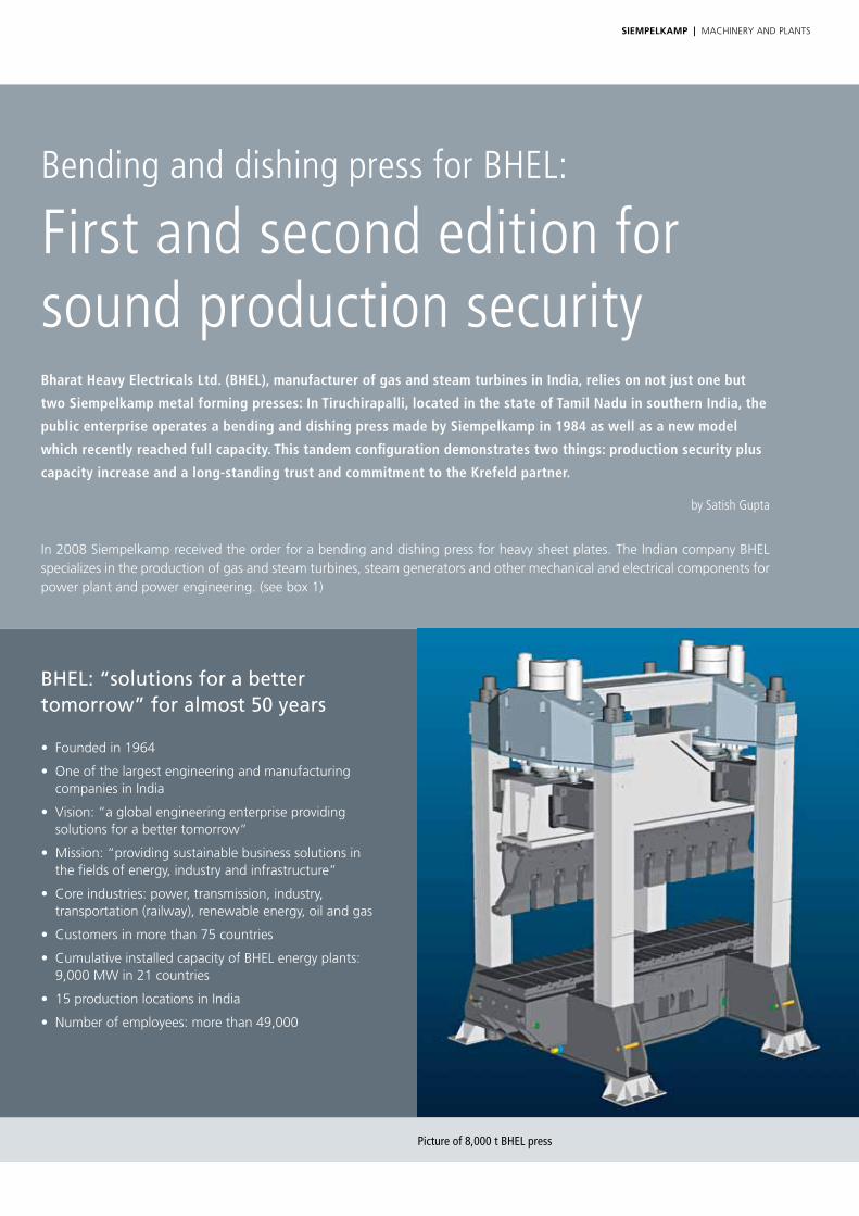
Picture of 8,000 t BHEL press
by Satish Gupta

SieMpelkAMp | MACHIneRy AnD PLAnts 1716
the modern bending and dishing press is optimally suited for the BHeL production spectrum: It manufactures pressure vessel com-ponents which are used in power plants. the order was triggered by an increasing demand for electrical energy (e.g., for power plants with a capacity of up to 500 MW) and, as a result thereof, an increasing demand for large pressure vessels. Furthermore, the new press ensures the power plant constructor’s ability to supply.
With a daylight of 6,000 mm (20 ft) the press can manufacture components with a diameter of up to 2,300 mm (7.5 ft). the press applies a pressure of up to 80 Mn (8,000 t) and the bending process takes place at material temperatures ranging from 870 to 1,010 °C.
the performance of this hydraulic press also sets benchmarks in other areas, for example regarding the dimensions of the sheet plates that it processes: the press bends plates with a thickness of up to 205 mm (8 in) and a length of up to 11,500 mm (38 ft). the width of the plates can be up to 4,000 mm (13 ft).
siempelkamp supplied the press as a complete solution. Its instal-lation started in 2010. Apart from the press, the scope of supply for this order included also the shifting table for quick tool changes as well as the bending and dishing tools. the dishing
tool produces the dished ends with only one press stroke. Also included in the order: two manipulators which are responsible for the precise positioning of the components inside the press. For the press and manipulator controls siempelkamp uses the state-of-the-art PLC of Generation s7 powered by in-house developed software.
the press compensates the deflection of the tools which have the lengths of 11,000 mm. the result: After calibrating, the desired diameter of the bent shell-halves deviates only 0.5% from the interior diameter and the profile departure amounts to only ± 4 mm. Manipulators and rollers, which are integrated in the upper and lower tool, position the plate/shell-halves precisely during the forming process. this saves times and money: the forming process for a shell-half takes only 30 minutes!
Another special feature which characterizes the BHeL press: traditional dishing presses cannot form plates to dishes up to the edges of the work piece. In those presses the dish edges – up to triple the thickness of the plates – are not formed properly after the forming process. the siempelkamp method allows the for-ming of the plates extremely close to the edges. Consequently, the material is used to an optimum. the small remaining edge area of the plate is used for the weld seam.
Moving beam inside the production facility Upper die during mechanical machining at Siempelkamp
Production of pull-back cylinders for BHEL Lower die

SieMpelkAMp | MACHIneRy AnD PLAnts
Heavy industry: the manufacturing process
the 80 Mn press is an overall concept by siempelkamp – not only in terms of the scope of supply but also regarding the idea, design, and production. the mobile beam, the frame, the cylinders as well as the lower
Plate bending and dishing: two processes combined in one press
two processes and two presses were commonly necessary for the forming of sheet metal plates to dished ends and the shell halves for pressure vessels. siempelkamp com-bined both processes in its plate bending and dishing press. this large hydraulic press carries out the hot forming process at material temperatures ranging from 870 to 1,010 °C as well as the cold calibration process to the final dimension. A separate press for the cold forming and calibration process is therefore no longer necessary. the thickness of the plates which can be processed on these siempelkamp presses is impressive. so is the applied pressing force, which goes up to 80 Mn.
tool are manufactured in Krefeld as welded constructions. the upper tool made of cast steel was machined by siempelkamp. Krefeld specialists were also responsible for the installation.
the lower tool is a specialty within this overall concept: It contains numerous new
components like newly designed lifting rollers and lifting beams with bending jaws. the in-house developed gear unit with ground cam discs represents a special siempelkamp design.
the new forming press processed its “first plate” in 2011. the inauguration of the equipment was part of a ceremony held by BHeL. After passing its acceptance test, the press has been running at full capacity since March 2012.
New and old forming press: total production security
With this project BHeL focuses not only on an excellent press concept but also on putting its production capacity on two reliable pillars. Back in 1980 the power plant builder ordered a siempelkamp plate bending and dishing press of the same design for the same location. except for the lower tool and the manipulators there is no difference between both concepts – other than the 30 years between them.
Press no. 2 is relieving press no. 1. BHeL has distributed the forming capacity of press no. 1 over both models in order to guarantee production security. the older press was upgraded at the end of 2012 – also with siempelkamp support. the moving beam and the upper tool were replaced; traces of wear removed after 30 years of successful operation. this press is fully operational again and operates, together with the new press, at full force!
Forming process of a half shell
Dishing of a dished end for a pressure vessel

SieMpelkAMp | MACHIneRy AnD PLAnts 1918
Energy demand in India: rapid increase
BHeL’s production strength falls on fertile ground within the energy sector: Due to the demographic development – the Indian population is expected to grow to over 1.5 billion people by 2030 – India’s demand for energy will rapidly increase. the dynamic development of the economy will also contribute to this energy rise.
the International energy Agency (IeA) predicts that the world’s energy demand will increase by one third by 2035 – whereupon India and China will be responsible for one half of this growth.
In this respect the topic “energy supply” is top priority on India’s agenda: Alternative energy sources are supposed to play bigger roles in the energy mix in the future. nevertheless, India will not be able to do without fossil fuels in the medium term. 65% of the currently installed electricity-generating capacities are conventional power plants (coal, gas, oil), as the economic magazine Indien- Contact published in 2012.
Top left:Lower lifting rollers
Top right:Customer visit in Krefeld
Bottom left:Installation of press
Bottom right:Plate bending and dishing press

SieMpelkAMp | MACHIneRy AnD PLAnts
Conveyor belt plants made by Siempelkamp:
Exciting innovation with technological advantage!An exciting Siempelkamp development in the area of rubber presses: At the end of 2012 and the beginning of 2013 two
conveyor belt plants were delivered to a long-term customer. The innovation incorporated in both plants: A new cable
tensioning concept replaces the traditional hydraulic cable tensioning device and gives the plant operator 100% control
over the cable tension distribution. A new roller comb concept also opens up decisive advantages.
In 2012 both projects not only represented gratifying milestones of a long-term cooperation but also a technological advantage. the traditional cable tensioning device has been replaced with a new cable tensioning concept: An electromotive individually controlled tensioning system including measuring and control functions was integrated into the device. “the decisive advan-tage for the plant operator: the measuring device allows the operator to measure and control the tension of each individual steel cable with up to 3,900 n. At any time the plant operator has 100% control over the actual steel cord tension distribu tion. this provides exact reporting and a high quality level,” explains steffen Aumüller, sales Manager for rubber presses at siempel-kamp. Differences in the individual cable tensioning levels are
within a tolerance zone of +/– 2 %. With this concept the plant operator can use cables with differ ent diameters and control each motor individually. Compared to the traditional hydraulic system, this system offers unlimited potentials!
Siempelkamp development: the new roller comb concept
the new roller comb concept also opens up advantages for conveyor belt manufacturers. they can be summed up with the slogan “flexibility instead of friction”. For the first time, our plants include a roller comb which replaces the fixed finger comb used in previous concepts. Inserted in safety chucks, the concept allows quick product changeovers.
Conveyor belts in use
by Steffen Aumüller

SieMpelkAMp | MACHIneRy AnD PLAnts 2120
the significant advantage of this concept: Due to the fact that the roller comb is pivot-mounted, zinc abrasion of the cables and friction are reduced to a minimum. “the tension that is applied inside the cable creel is also applied over the production width,” says steffen Aumüller. the roller comb separates the cables for production in front of the moveable compactor lorry and thus sets the course for reliable quality. the comb is designed for a maximum traction force of 80 t. Additional features of the roller comb concept: A support roller for the roller comb avoids too much flexibility – that is, excessive deflection. With the traditional hydraulic system the cables are fixed under tension, the lorry has to move. Another aspect of the new system: since the cables are tensioned by a motor, it does not matter whether the cables are tensioned during standstill or while they are moving. “the tension distribution can be controlled in either case,” explains steffen Aumüller. In september the new con-cept was tested at the siempelkamp headquarters in Krefeld, Germany. the delivery took place at the end of 2012 and the beginning of 2013.
Regarding the topic of cost reduction in the area of worldwide mining, it is becoming increasingly more important to change the strategy in accordance with the concept of “in-pit crushing and conveying”. However, this should not just be carried out according to the motto “away with the truck, use the belt” – but instead the best available concept for continuous conveyor technology on the market should be used. “the decisive factor here is the targeted and precise reporting of the process parameters which we have consistently advanced for both new plants,” summarizes steffen Aumüller.
Complete production line
Compactor lorry
Conveyor belt plants with innovative boost: key data*
Plant type: plant for the production of textile as well as steel cord conveyor belts with multi-piston down-stroke press, including 2-track production
Press length: 18,480 mm
scope of supply: complete steel cord conveyor belt line
Finished belt width: 900 – 2,600 mm
Finished belt thickness: textile conveyor belts: 5 – 50 mm
steel cord conveyor belts: 8 – 50 mm
tiers/Channels: 2/2
number of cables on the cable creel: plant 1: 416, plant 2: 336
number of cables on roller comb: no limit
Maximum cable tension: 3,900 n per cable
Cable diameter: 3 – 15 mm
specific pressure: 400 n/cm²
* Unless otherwise indicated, all data shall be considered for both plants
Left: Spools with direct tensioning drives, Right: Tension measurement device
SieMpelkAMp | MACHIneRy AnD PLAnts
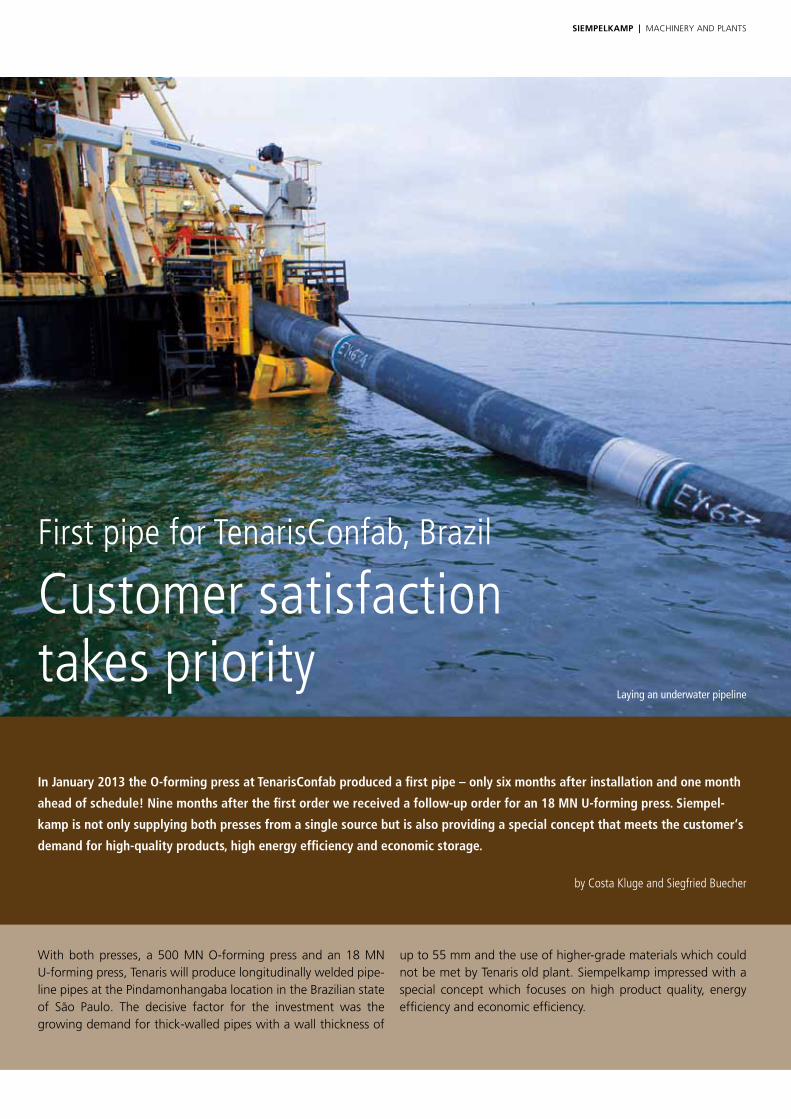
First pipe for TenarisConfab, Brazil
Customer satisfaction takes priority
In January 2013 the O-forming press at TenarisConfab produced a first pipe – only six months after installation and one month
ahead of schedule! Nine months after the first order we received a follow-up order for an 18 MN U-forming press. Siempel-
kamp is not only supplying both presses from a single source but is also providing a special concept that meets the customer‘s
demand for high-quality products, high energy efficiency and economic storage.
by Costa Kluge and Siegfried Buecher
With both presses, a 500 Mn o-forming press and an 18 Mn U-forming press, tenaris will produce longitudinally welded pipe-line pipes at the Pindamonhangaba location in the Brazilian state of são Paulo. the decisive factor for the investment was the growing demand for thick-walled pipes with a wall thickness of
up to 55 mm and the use of higher-grade materials which could not be met by tenarisʼold plant. siempelkamp impressed with a special concept which focuses on high product quality, energy efficiency and economic efficiency.
Laying an underwater pipeline
SieMpelkAMp | MACHIneRy AnD PLAnts 2322
TenarisConfab, Brazil
tenarisConfab belongs to the leading manufacturers and sup-pliers of welded steel pipes for the energy industry. the plant in Pindamonhangaba has a yearly output of roughly 550,000 t of pipes. With 26,980 employees the company achieves annual sales totaling Us$ 9.97 billion.
Pipeline pipes made by tenaris are used worldwide even under the toughest conditions. the application areas which include off-shore solutions in the Arctic or underwater pipelines require high product quality. the pipes have to be wear-resistant and corrosi-on-resistant, have to have high mechanical strength at extreme temperatures and difficult weather conditions and a long lifespan. these high quality demands on the product are passed on to siempelkamp by the customer.
High-strength materials for high product quality
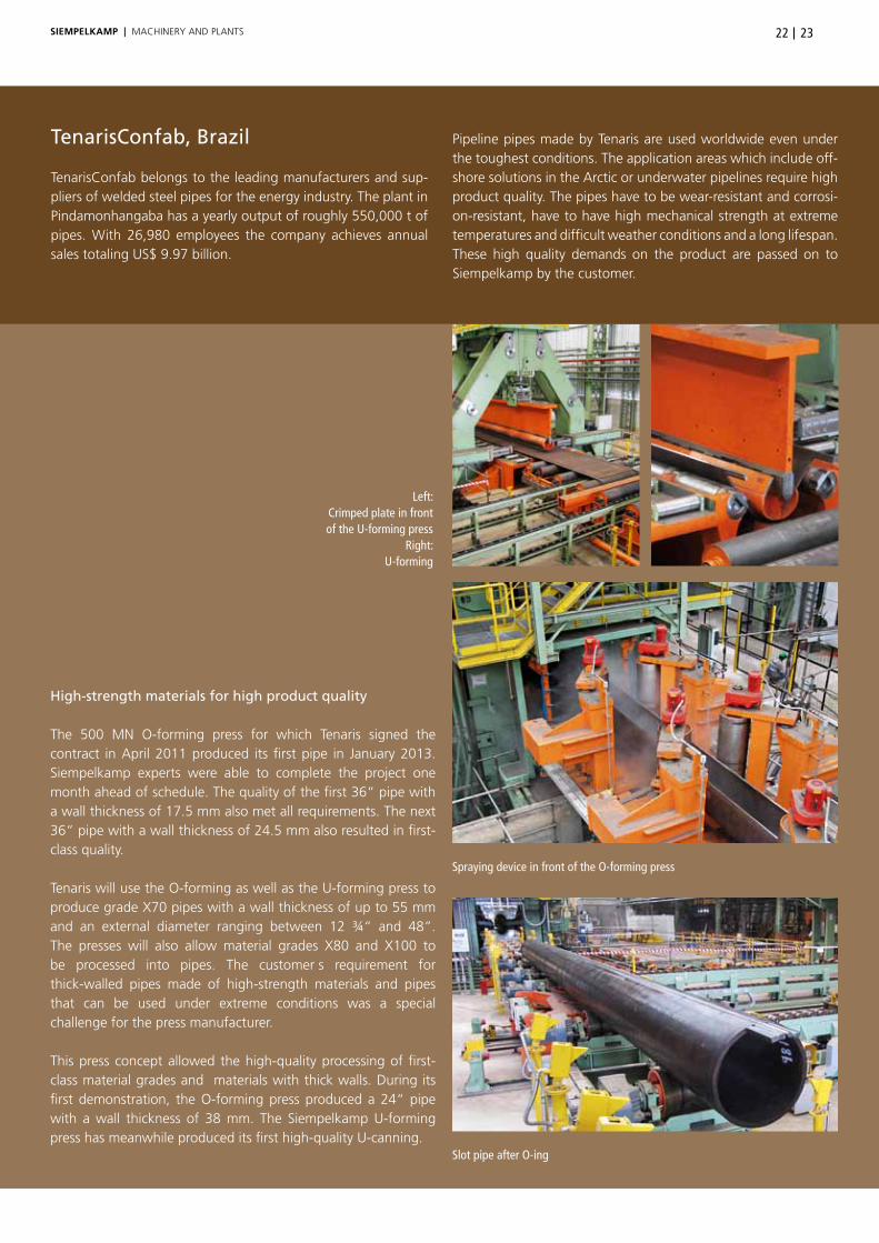
the 500 Mn o-forming press for which tenaris signed the contract in April 2011 produced its first pipe in January 2013. siempelkamp experts were able to complete the project one month ahead of schedule. the quality of the first 36“ pipe with a wall thickness of 17.5 mm also met all requirements. the next 36“ pipe with a wall thickness of 24.5 mm also resulted in first-class quality.
tenaris will use the o-forming as well as the U-forming press to produce grade X70 pipes with a wall thickness of up to 55 mm and an external diameter ranging between 12 ¾“ and 48“. the presses will also allow material grades X80 and X100 to be processed into pipes. the customerʼs requirement for thick-walled pipes made of high-strength materials and pipes that can be used under extreme conditions was a special challenge for the press manufacturer.
this press concept allowed the high-quality processing of first-class material grades and materials with thick walls. During its first demonstration, the o-forming press produced a 24“ pipe with a wall thickness of 38 mm. the siempelkamp U-forming press has meanwhile produced its first high-quality U-canning.
Left: Crimped plate in front of the U-forming press
Right:U-forming
Spraying device in front of the O-forming press
Slot pipe after O-ing
SieMpelkAMp | MACHIneRy AnD PLAnts
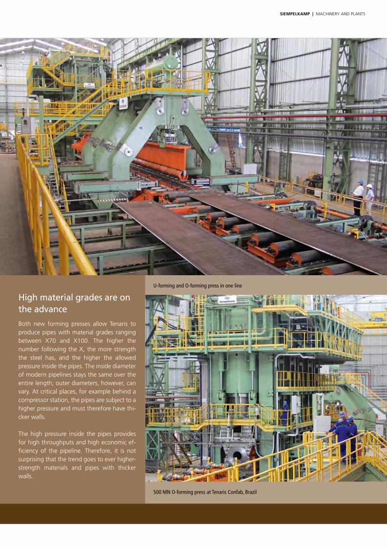
High material grades are on the advance
Both new forming presses allow tenaris to produce pipes with material grades ranging between X70 and X100. the higher the number following the X, the more strength the steel has, and the higher the allowed pressure inside the pipes. the inside diameter of modern pipelines stays the same over the entire length; outer diameters, however, can vary. At critical places, for example behind a compressor station, the pipes are subject to a higher pressure and must therefore have thi-cker walls.
the high pressure inside the pipes provides for high throughputs and high economic ef-ficiency of the pipeline. therefore, it is not surprising that the trend goes to ever higher-strength materials and pipes with thicker walls.
U-forming and O-forming press in one line
500 MN O-forming press at Tenaris Confab, Brazil

SieMpelkAMp | MACHIneRy AnD PLAnts 2524
Two presses – one process
Both presses produce high-quality and reproducible forming results even with high-strength plates. the 500 Mn o-forming press is equipped with five main cylinders over a length of 12.5 m. each cylinder has a diameter of 1900 mm. this translates into a force of 40,000 kn per meter. Combined with siempelkamp‘s patented multi-cylinder parallelism control, the control ensures that the moving beam maintains a position parallel to the press table within a tolerance of +/- 1 mm over the entire length. the modular tool concept, which was developed together with the customer, significantly reduces the tool costs per each pipe diameter. Furthermore, the press features quick and, at the same time, precise adjustments to different plate sizes.
the 18 Mn U-forming press replaces an old 9 Mn U-forming press from the 1970s which no longer met the demands for new high-quality products. Instead of updating the old press, it was decided to acquire a new press to use modern technology for both plate-forming processes, the o-forming as well as the upstream U-forming process. With an automated tool change system and an automated clamping system for tool segments, the set-up times are reduced.
Innovative drive systems provide for efficient use of energy
A special feature for both tenaris presses are the innovative and energy-efficient drive systems. For the basic movement of the moving beam of the 500 Mn o-forming press, the oil-hydraulic drive was equipped with variable-speed high-pressure pumps. With this control concept the potential energy as well as the energy stored inside the elasticities during the forming process can be recovered. Following, the energy is then fed back as electricity into the supply network (energy recovery). With the intelligent control system, the innovative hydraulics concept of the o-forming press corresponds to tenaris‘ʼ philosophy to conserve the environment through the efficient use of resources.
the U-forming press also achieves exceptionally high energy efficiency. the press‘ hydraulic drive is also equipped with the same variable-speed high-pressure pumps as are used with the o-forming press. the advantage of this system compared to conventional solutions is that the amount of energy used is the actual amount needed for the forming process. siempelkamp‘s innovative press control also guarantees the highest operational safety.
In combination with the electrical control, the hydraulic control system guaran-tees exact parallel movement of the bending blade as well as of the horizontally working bending beams under all operating conditions. the counterforce is applied by a hydraulic cushion. the formerly common mechanical end stops are omitted. the control blocks are located very close to the machine. thus, the pipelines are short to the respective consumers which results in high dynamics for the compensation of disturbance variables.
Complete crimping, U-forming and O-forming technologies from a single source
siempelkamp pipe forming presses have been manufacturing large longitudinally-welded pipes for pipeline applications for more than 45 years. For all three process steps we provide the optimal solution.
In the first process step, the longitudinal plate edges are bent inside a crimping press. the closed-frame design guarantees a straight crimping contour over the complete length and a precise longitudinal seam of the pipe. siempelkamp U-forming presses are used for the second process step in the production of large, longitudinally welded pipes. Due to the precise interaction between lateral cylinder, bending blade and counter beam with hydraulic cushion function, an optimal U-canning is produced.
our o-forming presses are the last link in the process chain. As the name already suggests, during this process the previously manufactured U-cannings are formed with another tool into pipes. A weld seam completes the production of a pipe in a later process. the homogenous stress distribution around the pipe diameter and the compliance with close tolerances by means of our automatic ram parallelism control ensures highly precise production. this precision is essential for the pipes which will later be used in pipelines.
In 1968 siempelkamp sold the first complete forming line including three presses to Mannesmann at the Duisburg Mündelheim location. the o-forming press had a force of 26,000 t. From this time on, siempelkamp continued to develop the technologies for the crimping, U-forming and o-forming processes and set new standards with its know-how in process technology.

SieMpelkAMp | MACHIneRy AnD PLAnts
FEM simulation of U-forming press
Casting at the Siempelkamp Foundry
The frames of the O-forming press for Tenaris at the Krefeld plant
The customer examines the press table for the O-forming press in Krefeld
3-D model of the O-forming press
Tool insert on large CNC lathe

SieMpelkAMp | MACHIneRy AnD PLAnts
Electro-slag welding process electro-slag welding is a very quick process due to the fact that a preparation of the weld seam is omitted. It is derived from resistance welding and is a special welding method for electrically conductive materials for which the connecting materials are heated until melting. After re-solidification of the fused material, a welded joint forms. Compression during and after the current flow results in a strong joint between both connecting materials.
Identical parts principle results in high storage efficiency
Finally, when it comes to both presses, tenaris profits from an identical parts principle. Identical parts are components that can be used as is in different products but that are not standard parts. Both tenaris presses – as all siempelkamp presses for metal forming –represent the perfect balance between custom design and standardized design. they are perfectly adjusted to the production needs of the customer and allow, due to the use of identical parts, a quick spare parts supply and high storage efficiency.
soon tenarisConfab in Brazil will be able to produce high-quality pipes for pipeline applications with the 500 Mn o-forming press and the upstream 18 Mn U-forming press in an energy-efficient and economical way.
FEM simulation of U-forming press
Main cylinder inspection by the customer Electro-slag welding
All from a single source – the Siempelkamp principle
All components for the tenaris U-forming and o-forming presses were manufactured in siempelkamp‘s machine factory at the company‘s headquarters in Krefeld. since January 2012 the siempelkamp Maschinenfabrik GmbH (machine factory) operates as an independent subsidiary and primarily manufactures products for the parent company, siempelkamp Maschinen- und Anlagenbau (machine and plant engineering). Already three years ago the strategic decision to equip the siempelkamp manufacturing shop for the production of heavy parts was made. In doing so, important synergy effects with siempelkamp Foundry were opened up.
this strategy provides siempelkamp with a unique selling point for precision- machined and pre-finished heavy castings made of ductile cast iron with spheroidal graphite. the tool carriers, cross beams and press tables of both presses for tenaris were cast at siempelkamp Foundry and surface-machined at siempelkamp‘s machine factory.
All 20 press frames of the o-forming press were welded using the electro-slag welding process. the machine factory has been applying this innovative method since november 2010. It is used when large amounts of weld metal are necessary, for example when connecting very thick cross sections or during the deposit welding of large areas. since this process does not require weld seam preparations, the production time for the machine factory and therefore the delivery time for the customer are reduced.
2726

v
Aeronautical research program inspires:
Siempelkamp press technology for high-precision fiber composite materials for the aerospace industry For many years Siempelkamp has been a competent press supplier to the aerospace industry. Its expertise in highly
precise fiber composite materials is now applied in a research project: In August 2012 the aeronautical research project
“TP*-Closed Box” started with Siempelkamp as the development partner of CTC-Airbus, xperion and the Fiber Institute
Bremen as well as the Technical University of Braunschweig.
*TP = thermoplastic
SieMpelkAMp | MACHIneRy AnD PLAnts
by Dr. Michael Schöler
v
2928SieMpelkAMp | MACHIneRy AnD PLAnts
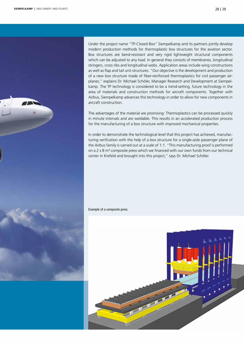
Example of a composite press
Under the project name “tP-Closed Box” siempelkamp and its partners jointly develop modern production methods for thermoplastic box structures for the aviation sector. Box structures are bend-resistant and very rigid lightweight structural components which can be adjusted to any load. In general they consists of membranes, longitudinal stringers, cross ribs and longitudinal webs. Application areas include wing constructions as well as flap and tail unit structures. “our objective is the development and production of a new box structure made of fiber-reinforced thermoplastics for civil passenger air-planes,” explains Dr. Michael schöler, Manager Research and Development at siempel-kamp. the tP technology is considered to be a trend-setting, future technology in the area of materials and construction methods for aircraft components. together with Airbus, siempelkamp advances this technology in order to allow for new components in aircraft construction.
the advantages of the material are promising: thermoplastics can be processed quickly in minute intervals and are weldable. this results in an accelerated production process for the manufacturing of a box structure with improved mechanical properties.
In order to demonstrate the technological level that this project has achieved, manufac-turing verification with the help of a box structure for a single-aisle passenger plane of the Airbus family is carried out at a scale of 1:1. “this manufacturing proof is performed on a 2 x 8 m² composite press which we financed with our own funds from our technical center in Krefeld and brought into this project,” says Dr. Michael schöler.

SieMpelkAMp | MACHIneRy AnD PLAnts
Bottom: Composite press for organo sheets
Aircraft wing production, Bremen, Germany
the press is a reference example of a new high-tech composite press gener-ation made by siempelkamp. After extensive test runs on a laboratory press at our in-house technical center in Krefeld and in close cooperation with different customers, the following parameters, providing benefits to the aeronautical research project, were used:
• Highest possible accuracy through directly-controlled hydraulic drives
• Optional use in the RTM or organo-sheet technology
• Unlimited use as open-die, closed-die, or gap impregnation press
• Modular construction for the simplified derivation of presses of any size from a basic design
the dimensional accuracy which is essential in the aircraft industry profits from the high precision of this press generation. “An airplane consists of up to 10,000 individual composite components. A lack of accuracy can result in stresses which have to be avoided at any cost for safety reasons. therefore, it is productive to use composite presses which increase and secure quality and dimensional accuracy,” explains Dr. Michael schöler.

3130SieMpelkAMp | MACHIneRy AnD PLAnts
Composite Technology Center Stade (CTC-Airbus): project partner at a glance
Profile CtC: established in 2001 as a 100% Airbus subsidiary
Management: Prof. Axel Herrmann, Dr. Jens Walla
objective: development of series production technologies for the pro-duction and assembly of carbon-fiber reinforced plastic com-ponents in aircraft construction
CFK: = carbon-fiber reinforced plastic
CFK at the Airbus factory stade: In 1983 the first vertical tail made of carbon-fiber reinforced plastic was produced in stade. since 1996 the Airbus plant in stade has been a straight composite plant and has been manufacturing the vertical tails for all Airbus aircrafts. the current product spectrum: next to all vertical tails, the factory also manufactures the rear pressure bulkheads for the A380, wing shells for the A400M and the A350 XWB as well as fuselage shells for the A350 XWB.
Certifications: DIn Iso 9100 and 14001
Awards: for example JeC Composites Innovation Award 2011 for the continuous pre-forming of double t-profiles with variable height adjustment
Ambitious aeronautical research program
since 1995 the German federal government has supported the German aerospace industry with an independent aeronautical research program. this project focuses on creating a competitive funding and research framework for internationally competing companies of this sector. the specific aeronautical research program also supports German companies in securing their technological expertise and remaining internationally competitive at eye level.
the German Federal Ministry of economics and technology is responsible for the project. Airbus is considered the group leader of the ongoing aeronautical research project LuFo IV, which began in August 2012 and will end in March 2015.
An important project partner is the German Aerospace Center. Its competences include the areas of drives, numerical simulations, material technology, and helicopters.

SieMpelkAMp | MACHIneRy AnD PLAnts
Siempelkamp’s background for Airbus: from rubber pad press to high-tech composite press
Back in the 1970s siempelkamp already made an important step towards the current joint aeronautical research project “tP-closed Box”: Back then the company developed rubber pad presses for Airbus and its sub-suppliers. these press systems have produced large quantities of precision profiles for airplane structures.
Furthermore, regarding the supply of large presses for titanium processing and aluminum-based special alloys, siempelkamp is a leading provider for the aviation sector.
“next to titanium sponge presses for raw material production we supply large open-die and closed-die forging presses for the processing of titanium, aluminum and special alloys. our presses apply forces of up to 50,000 t (55,116 Us tons) and manufacture chassis components, the main frames for the Boeing 747 and the Airbus A380 as well as blanks for engine shafts and compressor discs,” says Dr. Michael schöler.
A classic product and important siempelkamp reference in the area of composite manufacturing are also the multi-daylight sandwich panel presses which have been supplied to eADs’ location elbe Flugzeugwerke GmbH in Dresden since 1993. Here
the focus is on development and production of light-weight com-ponents for the interior construction parts of all Airbus models.
siempelkamp presses play an important role in this aspect: they manufacture sandwich panels used as flooring panels, wall and ceiling panels or cargo compartment components. In close co operation with our customer elbe Flugzeugwerke we further optimized the production of sandwich flooring panels. A pleasing milestone: the approval for this latest generation of carbon-fiber reinforced composite panels has already been issued.
As a confirmation of this fruitful cooperation a fifth sandwich press was ordered at the end of March 2012, which has mean-while started operation.
Based on the extensive knowledge in the construction of large and precise presses siempelkamp started to pursue a new and ambitious objective approximately two years ago: the develop-ment of the above mentioned press for composite panels. Dr. Michael schöler: “on the base of preliminary considerations and our experiences from laboratory trials we supplied the first newly-developed siempelkamp composite press to Advanced Composite engineering GmbH (ACe) in Immenstaad in March 2013 – including the successful start-up!”
40,000 t press for the production of structural components for the aerospace industry
Flooring panels for the aircraft industry Titanium compacting press

As part of the aeronautical research project the joining process of fiber-reinforced thermoplastic components is further developed. Here, the use of an induction welding process is pursued. By using this type of welding technology and prefabricating precisely pressed parts, the connecting elements commonly used in the aircraft structure today are avoided. Compared to drilling and fastening processes, the joining process is tremendously accele-rated and simplified.
this opens up the possibility to manufacture large textile compo-nent parts with a high degree of value added. A big opportunity for the economic success of this development results from the fact that high quantities of thermoplastic fiber-reinforced compo-nent parts will be needed for series production of new aircraft programs. siempelkamp and its partners would like to provide the necessary corresponding production methods in time.
“tP-Closed Box” already opens up new ideas and perspectives even before the project’s completion in March 2015: “Due to the good and trusting cooperation within the Group we are con-sidering other projects in the area of aeronautical research,” says Dr. Michael schöler thinking about the future.
3332SieMpelkAMp | MACHIneRy AnD PLAnts
Aeronautical research project – current situation: focusing on the technological readiness levels
As part of the “tP-Closed Box” project the siempelkamp research and development team together with Airbus dedicates itself to new challenges regarding the Airbus. since the airline industry is urgently requiring modern production methods and shorter production times, the project team is risking all to reach several technological readiness levels until the project comes to an end. these technological readiness levels measure the technological degree of readiness for a development and are recorded on a scale from 1 to 9. these levels follow a highly systematic approval procedure controlling the approval of new components and production methods in the aerospace industry.
What are the key challenges? Challenges primarily regard the forming properties of thermoplastic sheets with strongly varying laminate structures. For presentation purposes of a load-bearing design this behavior is examined in detail with so-called coupon tests. these tests can be performed on the new laboratory com-posite press in Krefeld.
the objective of this work package is to reduce the cycle times by approx. 70% compared to the current production process by using modern siempelkamp press technology.
Organo sheets Special press for the RTM process
SieMpelkAMp | MACHIneRy AnD PLAnts
Strothmann transfer system for Volkswagen:
On the right track thanks to Siempelkamp’s
expertise in composite manufacturing Airbus is not the only one that counts on Siempelkamp when it comes to composite manufacturing. Volkswagen AG also uses the excellent properties of composite manufacturing developed by Siempelkamp‘s Research and Development for its own purposes. The Siempelkamp subsidiary Strothmann has installed a highly complex yet user-friendly transfer system at Volkswagen. This system profits from custom-built composite bars designed by Siempelkamp for Strothmann feeders.
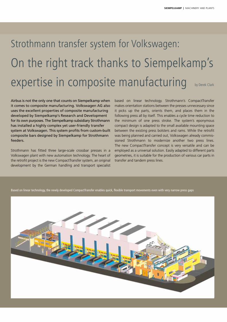
strothmann has fitted three large-scale crossbar presses in a Volkswagen plant with new automation technology. the heart of the retrofit project is the new Compacttransfer system, an original development by the German handling and transport specialist
based on linear technology. strothmann’s Compacttransfer makes orientation stations between the presses unnecessary since it picks up the parts, orients them, and places them in the following press all by itself. this enables a cycle time reduction to the minimum of one press stroke. the system’s eponymous compact design is adapted to the small available mounting space between the existing press bolsters and rams. While the retrofit was being planned and carried out, Volkswagen already commis-sioned strothmann to modernize another two press lines. the new Compacttransfer concept is very versatile and can be employed as a universal solution. easily adapted to different parts geometries, it is suitable for the production of various car parts in transfer and tandem press lines.
by Derek Clark
Based on linear technology, the newly developed CompactTransfer enables quick, flexible transport movements even with very narrow press gaps

SieMpelkAMp | MACHIneRy AnD PLAnts 3534
Line layout
Before the retrofit, the handling equip-ment was coupled with the press line’s mechanical drive shaft. now, the transfer system and the presses have been decoupled, and mechanical wear has thus been minimized. stripping the 59,000 kn press, 600 t of steel and copper were removed and assigned for internal recycling.
only the press bolsters, press drives, and foundations remained as they were. one of the specifications for the modernization project was a systematic standardization in order to facilitate maintenance and troubleshooting. Presses from various manufacturers and the respective diverse control systems were to be visualized on a uniform surface. Accordingly, the higher-level control system and the safety
controller should also be designed consistently and transparently. In the retro fitted press line, the press rams are attached to the shaft with a 30 degree offset from each ram to the next. the Compacttransfer system is synchronized with the movements of the press rams in real time. It can thus work with a minimum maneuvering space, which enables an even higher number of strokes.
The CompactTransfer – a solution tailored to small press gaps: all drives are safely positioned adjacent to the press line
integrates a telescope piece which allows for dynamic length compensation. the Compacttransfer halves can thereby – within limits – travel in different directions. thanks to the new transfer automation technology, Volkswagen was able to increase the number of strokes from 14 to 16 per minute.
Composite bars: low weight, high rigidity
the high number of cycles that the new transfer system allows is accompanied by high speeds and accelerations. Due to its slim geometry the crossbar cannot be subject to vibrations caused by the jolt of fast starting and reversing motions. In order to avoid vibrations, siempelkamp put its expertise in composite manufacturing to use: the crossbar was designed as a composite bar. the special carbon-fiber design combines two important properties that are essential for the feeder: on the one hand, low weight, and on the other hand,
high rigidity of the crossbar. “this concept was developed together with our develop-ment partner luratec AG in Rostock. In cooperation with strothmann we once more demonstrated that synergies within the siempelkamp Group are possible in many ways and that they can set ever new milestones to the benefit of our customers,” says Dr. Michael schöler, Manager Research and Development at siempelkamp.
Capacity increase of the line
What is more, for the first time, the retrofitted press line allows for the separati-on of double blanks during transfer and for the transfer of up to four parts from one die to the next. thereby the line’s capacity for pressing small parts can be utilized much better now. the die change has also been automated, resulting in additional significant time savings.
Four linear axes and one rotating axis, each with its dedicated drive, enable the Compacttransfer system to execute extremely agile orientation functions. For maximum freedom of movement, the crossbar is suspended on two pivot joints. It
Blank loader

SieMpelkAMp | MACHIneRy AnD PLAnts
Space-saving parts transfer solution
strothmann has developed a handling system suitable for transporting all kinds of automobile parts from press loading through to end-of-line parts removal. the comprehensive automation concept consists of a blank feeder with a fully automatic tooling change system, the Compacttransfer system which is based on servo linear technology, and standard robots at the end of the press line. Programming the motion curves, strothmann used press simulation soft-ware from siemens to determine the most
efficient safe path. the theoretical maximum acceleration is 25 m/sec2 for the horizontal axis and 15 m/sec2 for the vertical axis. In practice, the system accelerates by 20 and 10 m/sec2 at the Volkswagen plant. It is designed for blank sizes up to 4,100 by 2,100 mm and for maximum payloads of 120 kg combined blank and tooling weight. Retrofitting the Compacttransfer system is a simple and fast process. A complete module can be exchanged within a few hours by just using the existing drill pattern on the press frames. In keeping with the drive for standardization and uncomplicated
Automatic tooling change
the set-up time has been significantly reduced through automation. strothmann has fitted the die change tables with frontal holding frames. now, whenever the press line needs to be set up for different parts, the Compacttransfer can simply place the crossbar in the bracket so that it is removed from the press line along with the dies. the operator can then loosen the quick release skewers on the crossbar and exchange the toolings.
Blank loading and end of line
the blanks are carted in front of the press line on Roundtracks from strothmann. two sRLM-2/120-type feeders unload the blank trolleys with a combined 18 strokes per minute. the trolleys feature lifting apparatuses which adjust the stack height mechanically. Double blanks are automatically detected and discarded. the sheets are washed and lubricated. As they are transported to the press by means of an indexed conveyor, four line cameras
detect their positions. the machine vision system analyzes the data and, based on the results, two centering robots correct the position of the blanks. the centering robots’ toolings are also exchanged automatically. the blank loader, which is also enabled for fully automatic tooling change, has a total of more than 80 servo axes.
maintenance, only standard parts were used for the linear motion bearings and drives. As specified by the customer, strothmann installed siemens drive technology for the particularly highly demanding tasks. In comparison with articulated arm systems, this solution therefore offers a range of advantages: the linear technology used for carrying out the complex and long transfer paths is simpler and more transparent for the operator, orientation stations are not required, and the drives are positioned where they cannot be destroyed by the dies.
Space is optimally utilized

SieMpelkAMp | MACHIneRy AnD PLAnts 3736
Strothmann has also automated the start of the press line, including blank loading and tooling change as well as the washing, lubrication, and centering stations
End-of-line solution from Strothmann: the parts are automatically oriented based on their size and shape before they are handed over to the transport containers
the final Compacttransfer system lays press parts directly onto the outfeed conveyor or a shuttle that transports them to the parts removal robots. the latter orient the parts in the right, ergonomic position for the operator who loads them into customized containers. the shuttle which can carry out translations as well as rotations provides further efficient methods for handing over parts to the removal robots.
Conclusion
the highly dynamic automation technology increases the press line’s throughput by 20 to 30 percent, depending on the specific sets of dies. energy consumption has been cut by up to 35 percent. Instead of two, up to four parts can be transported in one step now. “We have completed the re-commissioning of the press line on schedule for the new Golf 7 production launch,”
says Helmut Wiesing, sales Manager PressRoomAutomation at strothmann. If any more evidence of the customer’s satisfaction or of strothmann’s proficiency were required, the following facts are worth a thousand words: “By now, we have retrofitted the third press line in the Wolfsburg plant, and we have been commissioned to undertake the fundamental modernization of two more lines at Volkswagen’s emden site.”
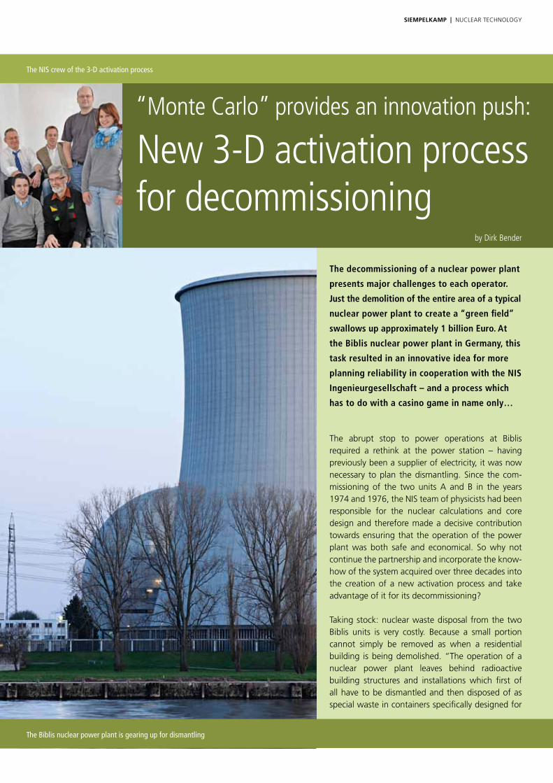
The decommissioning of a nuclear power plant
presents major challenges to each operator.
Just the demolition of the entire area of a typical
nuclear power plant to create a “green field”
swallows up approximately 1 billion Euro. At
the Biblis nuclear power plant in Germany, this
task resulted in an innovative idea for more
planning reliability in cooperation with the NIS
Ingenieurgesellschaft – and a process which
has to do with a casino game in name only…
“Monte Carlo” provides an innovation push:
New 3-D activation process for decommissioning
the abrupt stop to power operations at Biblis required a rethink at the power station – having previously been a supplier of electricity, it was now necessary to plan the dismantling. since the com-missioning of the two units A and B in the years 1974 and 1976, the nIs team of physicists had been responsible for the nuclear calculations and core design and therefore made a decisive contribution towards ensuring that the operation of the power plant was both safe and economical. so why not continue the partnership and incorporate the know-how of the system acquired over three decades into the creation of a new activation process and take advantage of it for its decommissioning?
taking stock: nuclear waste disposal from the two Biblis units is very costly. Because a small portion cannot simply be removed as when a residential building is being demolished. “the operation of a nuclear power plant leaves behind radioactive building structures and installations which first of all have to be dismantled and then disposed of as special waste in containers specifically designed for
SieMpelkAMp | nUCLeAR teCHnoLoGy
by Dirk Bender
The NIS crew of the 3-D activation process
The Biblis nuclear power plant is gearing up for dismantling
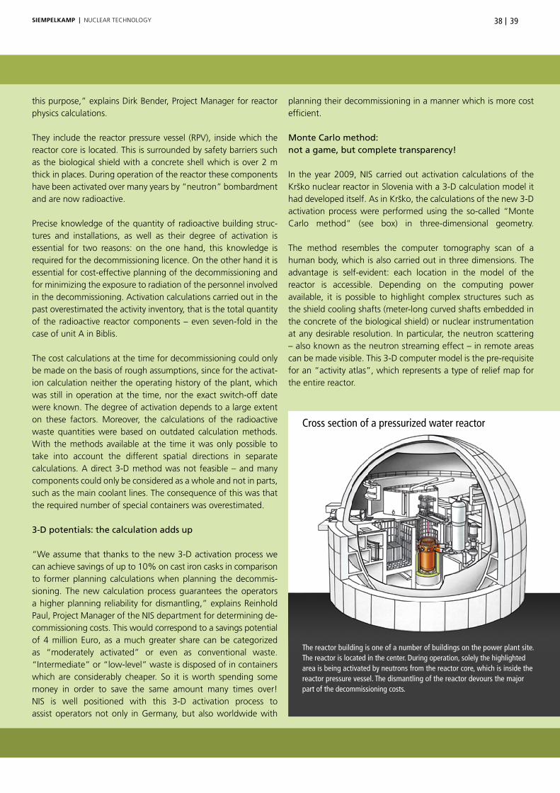
3938SieMpelkAMp | nUCLeAR teCHnoLoGy
this purpose,” explains Dirk Bender, Project Manager for reactor physics calculations.
they include the reactor pressure vessel (RPV), inside which the reactor core is located. this is surrounded by safety barriers such as the biological shield with a concrete shell which is over 2 m thick in places. During operation of the reactor these components have been activated over many years by “neutron” bombardment and are now radioactive.
Precise knowledge of the quantity of radioactive building struc-tures and installations, as well as their degree of activation is essential for two reasons: on the one hand, this knowledge is required for the decommissioning licence. on the other hand it is essential for cost-effective planning of the decommissioning and for minimizing the exposure to radiation of the personnel involved in the decommissioning. Activation calculations carried out in the past overestimated the activity inventory, that is the total quantity of the radioactive reactor components – even seven-fold in the case of unit A in Biblis.
the cost calculations at the time for decommissioning could only be made on the basis of rough assumptions, since for the activat-ion calculation neither the operating history of the plant, which was still in operation at the time, nor the exact switch-off date were known. the degree of activation depends to a large extent on these factors. Moreover, the calculations of the radioactive waste quantities were based on outdated calculation methods. With the methods available at the time it was only possible to take into account the different spatial directions in separate calculations. A direct 3-D method was not feasible – and many components could only be considered as a whole and not in parts, such as the main coolant lines. the consequence of this was that the required number of special containers was overestimated.
3-D potentials: the calculation adds up
“We assume that thanks to the new 3-D activation process we can achieve savings of up to 10% on cast iron casks in comparison to former planning calculations when planning the decommis-sioning. the new calculation process guarantees the operators a higher planning reliability for dismantling,” explains Reinhold Paul, Project Manager of the nIs department for determining de-commis sioning costs. this would correspond to a savings potential of 4 million euro, as a much greater share can be categorized as “mod erately activated” or even as conventional waste. “Intermediate” or “low-level” waste is disposed of in containers which are consid erably cheaper. so it is worth spending some money in order to save the same amount many times over! nIs is well positioned with this 3-D activation process to assist operators not only in Germany, but also worldwide with
planning their decommis sioning in a manner which is more cost efficient.
Monte Carlo method: not a game, but complete transparency!
In the year 2009, nIs carried out activation calculations of the Krško nuclear reactor in slovenia with a 3-D calculation model it had developed itself. As in Krško, the calculations of the new 3-D activation process were performed using the so-called “Monte Carlo method” (see box) in three-dimensional geometry.
the method resembles the computer tomography scan of a human body, which is also carried out in three dimensions. the advantage is self-evident: each location in the model of the reactor is accessible. Depending on the computing power available, it is possible to highlight complex structures such as the shield cooling shafts (meter-long curved shafts embedded in the concrete of the biological shield) or nuclear instrumentation at any desirable resolution. In particular, the neutron scattering – also known as the neutron streaming effect – in remote areas can be made visible. this 3-D computer model is the pre-requisite for an “activity atlas”, which represents a type of relief map for the entire reactor.
The reactor building is one of a number of buildings on the power plant site. The reactor is located in the center. During operation, solely the highlighted area is being activated by neutrons from the reactor core, which is inside the reactor pressure vessel. The dismantling of the reactor devours the major part of the decommissioning costs.
Cross section of a pressurized water reactor

SieMpelkAMp | nUCLeAR teCHnoLoGy
Activation – conventional materials become radioactive
Activation is the process by which materials become radioactive as a result of neutron radiation. Non-radioactive carbon 12 (chem. 12-C) for example, which is added in small quantities to the steel, is converted under neutron bombardment to radioactive carbon 14 (chem. 14-C), which is well known from the C14 dating method.
C14 – with a half-life of 5,730 years – is of no major significance for decom-missioning. This is completely contrary to many substances which are easily activated, as their nuclei capture neutrons particularly easily. For example cobalt: although only present in steel in traces, it is activated extremely easily and represents the dominant radioactive material in the steel in spite of its comparatively short half-life of 5.3 years. The half-life represents the period after which the activity of a substance has halved.
Neutron – a small particle with a striking effect Atoms are the smallest parts of the chemical elements. They are so tiny that 10 million atoms strung together measure approximately 1 mm. Much smaller than that – by a factor of approximately 10,000 – is the central atomic nucleus, which is surrounded by a shell of negatively charged electrons. If an atom corresponded to the size of the Cologne Cathedral, the nucleus of the atom would be the size of a cherry stone. The building blocks of the atomic nucleus are the positively charged protons and the neutrons. The neutron is charge-neutral – therefore its name. In the nuclear reactor, neutrons are produced by the fission of certain uranium atoms in the fuel elements which form the
Activation in the nuclear power plant – how does it arise?
Neutrons are essential for the generation of energy in nuclear power plants. They make use of their neutral charge in order to pass unhindered through the negatively charged shell of the atoms. If a neutron strikes the nucleus of an uranium atom (the fuel in a nuclear reactor), it can split this with the release of energy. In addition, two to three “fission neutrons” are released. After they have been slowed down by collisions with other atomic nuclei, these fast neutrons can split further uranium nuclei in the fuel. This is the wellknown chain reaction which keeps the nuclear reactor going.
A fraction of the neutrons produced escapes from the reactor core – similar to a boiler or car engine, in which thermal energy is lost to the environment. Nevertheless, this fraction is approximately as large as the quantity of rain-drops which would rain down on all continents of the earth simultaneously covering the entire surface – and that every second! Some of these neutrons penetrate deep into the 2 meter-thick biological shield and “activate” the reinforced concrete there.
Activation process of carbon by neutrons and subsequent radioactive decay to nitrogen by emitting a so-called beta particle and high-energy gamma radiation.
10
n 10
n
0-1 γe
126
136
radioactive decay
146
147C C C N
reactor core. On average, the fission of a uranium nucleus produces two to three so-called fission neutrons (as well as two approximately equal-sized pieces of debris and the release of energy).
As almost the entire mass of an atom is united in its nucleus, matter consists primarily of empty space. Because of its speed and type of material, the neutron can pass through matter almost unhindered. For this reason, outside the RPV the shielding is designed in such a way that no neutron from the reactor core can penetrate the biological shield to the outside.

4140SieMpelkAMp | nUCLeAR teCHnoLoGy
Decommis-sioning of the
conventional part = 35 mill. Euro
Decommissioning of the nuclear part = 800 mill. Euro
Nuclear waste disposal = 145 mill.
Euro
Opened reactor pressure vessel with a view to the fuel elements of the reactor core – next to it the cut-out of the 3-D activation model: the core is the source of the neutrons that leave the reactor core during operation and activate parts of the reactor building.
Dismantling costs of a pressurized-water reactor in Germany:
Total costs for the decommissioning back to the “green field” about 1 billion EuroAbout 680 cast iron containers are planned for the ”highly activated“ components. Savings of approx. 50 cast iron containers are possible in the decommissioning planning thanks to the use of the new 3-D activation process.
The innovation of the 3-D activation process
the new aspect is the inclusion of the nuclear calculation which maps the lifetime of the reactor, so to speak – in the case of Biblis nPP in Germany since its commissioning 39 years ago. “With the successful connection of the operational side to the decommissioning side in the activation calculation we are breaking new ground,” says Dr. stefan Jaag, one of the project participants who suc ceeded in doing this, proudly. “nobody has done this before us!”
For this to work, Jaag had to intervene in the Monte Carlo pro-gram and reprogram part of the computational code. Why the integration of the calculations of reactor operations is of such importance can be most easily explained using the metaphor of rain. With this it is possible to symbolize the stream of neutrons escaping from the reactor core: in reality it does not rain everywhere or permanently. It is therefore important to take into account the downtimes (in which hardly any fission neutrons are produced in the reactor core and therefore do not escape), as well as other important parameters from the past operations of the power station.

SieMpelkAMp | nUCLeAR teCHnoLoGy
One of the eight main coolant pipes at the Biblis NPP with a diameter greater than 1 m: The pipes of the hot leg lead the water with a temperature of almost 300 °C and a pressure of 155 bar from the reactor to the steam generators. They were partially activated by the neutron radiation from the reactor core.
In the computer model each reactor block is covered with more than 100,000 “detector cells” in each case. the flow of neutrons emerging from the reactor core over the 39 years of operation is simulated and the number of incoming neutrons in the detector cells registered over time. With this information, the activity in each detector cell is calculated. the RPV alone possesses more than 3,000 such cells!
the models of the two Biblis reactors were developed in close consultation with the decommissioning experts at nIs. they were able to incorporate all of the experience they had acquired during the decommissioning project in stade, Germany, in the modeling phase of the 3-D activation process. For example, in the case of the RPV, the grid arrangement of the detector cells was harmonized with the dismantling and packaging strategy. As a result, the number of containers required is optimized. Finally, the results of the activation calculations are stored in an “activity database”. By means of a simple input routine, the activity values can be shown for any location and cutout section within the reactor. As the next development step, the database is coupled to a 3-D activity visualization tool, with which it is possible to zoom in on cutouts directly on the screen or view them from another perspective.
Parallel processing saves time
the computational effort of the Monte Carlo calculation is im-mense: a single standard desktop PC would have had to calculate for an entire year (and that for one reactor block). thanks to parallel processing, it was possible to reduce the computing time to a few days. this processing power was necessary in order to obtain a high spatial resolution of the degree of activation. the reason for this is that only in this way is it possible to identify “hot spots” (areas with particularly high levels of radioactivity). Precise knowledge of the distribution of the activation within the reactor helps to effectively reduce the radiation exposure of the person-nel carrying out the decommissioning to a minimum. the team knows where the hot spots are located when they enter the reactor building and can therefore avoid them.
“With our high-resolution 3-D computational model we were even able to gain experience for the construction of new nuclear power plants,” explains project manager Dirk Bender. “We were able to identify which remote areas within the reactor building were activated by neutron bombardment and we can therefore make recommendations for better shielding.” For example, it would be possible to use alternative materials in these areas

SieMpelkAMp | nUCLeAR teCHnoLoGy 4342
The Monte Carlo method – cleverly analyzed!
Monte Carlo simulations are used if analytical formulas for the evaluation of processes in nature fail or their solutions are too complex. Questions from the world of finance and many other fields can also be answered relatively simply with Monte Carlo approaches.
In this method from stochastics (a branch of mathematics), ran-dom experiments performed very frequently play an important role. With the help of probability theory, problems are solved numerically. Here, use is made of the law of large numbers (in our case a large number of neutrons). the random experiments are carried out with the generation of random numbers (i.e. playing dice with numbers – in line with the casino in Monte Carlo).
specifically, in the 3-D activation process the Monte Carlo method is used to simulate the path that a neutron takes – from its generation somewhere in the reactor core to its destruction by nuclear capture. theoretically it would be possible to simulate the path taken by each individual neutron generated in the reactor. through the use of sophisticated tools from statistics it is possible to reduce the number of neutrons to be simulated to a manage-able level which desktop PCs that are currently commercially available and can cope with within a reasonable time. the results obtained from the Monte Carlo calculation satisfy the accuracy requirements which are usually demanded for such problems.
Neutron intensity distribution in a vertical cut of the 3-D activation model of the Biblis NPP, reactor B: Embedded by the reactor pressure vessel is the reactor core (black). Increased activation (red) dominates near the core. The activation decreases from green to blue. Areas of the reactor cavity floor or below the lid of the RPV floor underneath the head do not show any reactor neutrons (white). Parts of these components can be disposed of cost-effectively as conventional waste, as they have not been activated.
which can only be activated to a small degree by neutron bombardment.
As the Biblis site will soon begin with the decommissioning pro-cess, the next step on the agenda is sampling measurements of the reactor pressure vessel, the biological shield and other activated components. the comparison of the measurements with the calculation is considered to be the litmus test for the 3-D activation process. We are very curious to see the results and will report these to you!
Typical power distribution in an operating nuclear power plant: representation of a reactor core with its 193 fuel elements. Red areas generate greater thermal output and more neutrons than the areas marked in blue.
Presentation of the reactor neutron intensity distribution in a cut-out of the 3-D model of the upper reactor pressure vessel and the loop pipe: red = higher neutron intensity and thus higher activity.
New
3-D activation
process
Past meets with future:
The linking of the reactor’s power operation and its decommissioning

SieMpelkAMp | nUCLeAR teCHnoLoGy
Siempelkamp Krantechnik in permanent service for the MEYER WERFT shipyard:
Cranes and birds – high-level (wing) spans!In the last few years, the MEYER WERFT shipyard in Papenburg, Germany, known for the construction of special vessels
such as luxurious cruise ships, has developed into a good customer for Siempelkamp Krantechnik. Recently the shipyard
awarded a contract for the expansion of the functions of some working portals. This project was successfully implemented
in September 2012. What cranes and birds have in common in this connection is revealed by this report.
by Ute de Vries
A view to the MEYER WERFT in Papenburg, Germany, during the shipyard festival in 2009 (photo: MEYER WERFT)
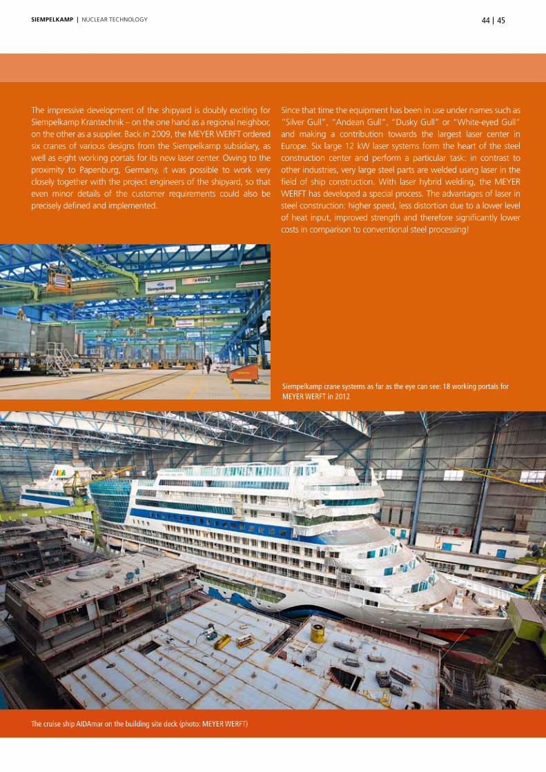
4544SieMpelkAMp | nUCLeAR teCHnoLoGy
the impressive development of the shipyard is doubly exciting for siempelkamp Krantechnik – on the one hand as a regional neighbor, on the other as a supplier. Back in 2009, the MeyeR WeRFt ordered six cranes of various designs from the siempelkamp subsidiary, as well as eight working portals for its new laser center. owing to the proximity to Papenburg, Germany, it was possible to work very closely together with the project engineers of the shipyard, so that even minor details of the customer requirements could also be precisely defined and implemented.
since that time the equipment has been in use under names such as “silver Gull”, “Andean Gull”, “Dusky Gull” or “White-eyed Gull” and making a contribution towards the largest laser center in europe. six large 12 kW laser systems form the heart of the steel construction center and perform a particular task: in contrast to other industries, very large steel parts are welded using laser in the field of ship construction. With laser hybrid welding, the MeyeR WeRFt has developed a special process. the advantages of laser in steel construction: higher speed, less distortion due to a lower level of heat input, improved strength and therefore significantly lower costs in comparison to conventional steel processing!
Siempelkamp crane systems as far as the eye can see: 18 working portals for MEYER WERFT in 2012
The cruise ship AIDAmar on the building site deck (photo: MEYER WERFT)

Contract upon contract: synergies that are literally self-supporting
the “working portal” concept developed specifically for the MeyeR WeRFt has proven its worth: after silver Gull and friends, siempelkamp Krantechnik received an extensive follow-up order in the first quarter of 2011: for the new expansion of the shipyard – the construction of a new hall with a length of 361 m, a width of 50 m and a height of 38 m – the crane specialist supplied ten new working portals and twelve ceiling crane systems of a special design with locking units. the installation and commissioning of the systems was carried out in stages in the third and fourth quarter of 2011.
Latest project: the expansion of the functions of some of the working portals, for example the retrofitting of additional hoisting gear or function enhancements. siempelkamp Krantechnik was also awarded this contract – this project was successfully implemented in september 2012. the range of products delivered comprised ten working portals with a load-bearing capacity of 6 x 250 kg each and a span of 43.40 m.
Working portals: one component in the sophisticated system
the working portals are special systems – that is crane systems specially developed for the specialship builders from emsland, Germany. At the MeyeR WeRFt there are a total of 22 working portals in use, of which 18 were supplied by siempelkamp.
the most recently supplied portals are designed as single girder bridge supporting structures, equipped with six knuckle boom
cranes each. these booms sweep seamlessly and flexibly across a large working area. each of these booms is equipped with various supply lines and contains an electric chain hoist. this is used to adjust the height of the attached welding cases, torch harnesses and special toolboxes with all of the required tools and consumable items. Advantages of the concept: the optimal, barrier-free and flexible supply of working materials is guaran-teed – and the workplaces can be set up individually. As a result, the working portals represent an important component of the sophisticated overall system.
And that is precisely the situation in hall 11, a synchronized flow line for the section equipment. Up to 30 x 30 m sections are equipped here at 4-hour intervals with pipes, cable trays, air conditioning ducts and other components. one equipment cycle takes four hours to complete: every three hours the flow line starts moving and for one hour conveys all of the sections simultaneously forward to the next construction area on special industrial trucks.
so-called load carriers contain equipment material that is adapted to the interval and section-specific. While the sections “flow” forward to the next construction area, the mobile load carriers are repositioned by the employees responsible for the section equipment and amongst other things lowered into the section with the help of the siempelkamp ceiling cranes.
the twelve single-girder ceiling cranes with a load-bearing capac-ity of 2.5 t each and a span of 18.90 m, as well as cantilevers on both sides, are arranged in two parallel crane runways and sweep seamlessly across the entire surface of the hall – like a bird’s wing beat!
The new hall 11 at MEYER WERFT equipped with Siempelkamp working portals
MEYER WERFT: founded in 1795 and in its sixth generation of family ownership (Photo: MEYER WERFT)
SieMpelkAMp | nUCLeAR teCHnoLoGy
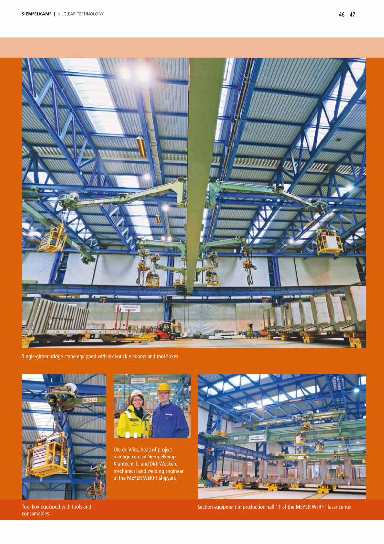
4746
Section equipment in production hall 11 of the MEYER WERFT laser centerTool box equipped with tools and consumables
Single-girder bridge crane equipped with six knuckle booms and tool boxes
Ute de Vries, head of project management at Siempelkamp Krantechnik, and Dirk Wobken, mechanical and welding engineer at the MEYER WERFT shipyard
SieMpelkAMp | nUCLeAR teCHnoLoGy

Old site of the MEYER WERFT in Papenburg, Germany: view to the industrial monument ”Bockkran“ (gantry crane), a steam-driven crane. Since the late 40s, the cranes are driven electrically.
Gulls and cranes – moving around in pairs
the comparison with bird life is self-evident for several reasons. For example, the crane systems on the site of Germany’s largest and oldest shipyard are not given inventory numbers, but instead bird names in order to identify them. twelve cranes form six pairs – and therefore six “gull couples” named Glaucous-winged Gull, Grey Gull, Red-legged Kitti-wake, Black-billed Gull, Franklin’s Gull and Relict Gull. Because also the genuine birds come along in twos.
the cranes are designed as master and slave cranes. on the one hand, the twelve cranes can be used completely independently of one another – and on the other hand the crane pairs can be locked together at any position in the hall. then two individ-ual cranes form a joint crane and transport long loads together. Furthermore, the trolley of one crane in an assembly-hall nave can cross over to the adjacent nave and transport loads. this concept offers optimum flexibility that is precisely in line with the wishes of the MeyeR WeRFt!
All cranes at MEYER WERFT have bird names
SieMpelkAMp | nUCLeAR teCHnoLoGy

4948SieMpelkAMp | nUCLeAR teCHnoLoGy
Why do all of the cranes at the MEYER WERFT have birds’ names?
“Robin needs new wheels”: at the MeyeR WeRFt shipyard, each crane is provided not with an inventory number, but with a large type plate bearing the name of a bird.
Dirk Wobken (see also the interview) was able to tell us why that is. With the large number of cranes on the shipyard site, an easy-to-remember arrangement or identification of the cranes had to be guaranteed. And birds’ names are easier to remember than numbers.
At the beginning, the bird names were issued similar to the size of the crane: the mighty 800 t crane was given the name “Imperial eagle”, the small 2 x 2 t crane is used under the name “Cockatiel”. With the large number of cranes that have been installed in the meantime, it is no longer possible to continue awarding names with the size ratio of the crane to the bird, so that now a very handsome crane has to be satisfied with the name “Black-billed Gull”.
today, the MeyeR WeRFt maintains its own bird book, in which the types of bird that have already been assigned are ticked off. Among the huge number of cranes on the gigantic shipyard site we there-fore encounter not only sparrows and all types of parakeets, but also various gulls and of course the condor, a 600 t crane. the bird names are a nice tradition at the Papenburg shipyard in Germany and make it easier to tell the cranes apart in everyday life.
From the mechanical crane to the ornithological crane
By the way: the birds and mechanical cranes are associated by the history of the word. the mechanical crane is actually a “crane of the air”. the first lifting devices, consisting of a vertical column and an inclined upward boom, were reminiscent of the long neck and beak of a standing crane.
It was no wonder then that even the ancient Greeks named the structure after the bird known as the crane. In the Middle Ages the German form “Kranich” for the bird was shortened to “Kran” for the mechanical crane. In some languages the word for the mechanical “crane” and the bird “crane” is the same – not only in english, for example, but also in French – “grue” – or Italian – “gru”. In Dutch the mechanical crane is a “kraan”, the bird a “kraanvogel” (vogel = bird).
Interview: No shipbuilding without (Siempelkamp) cranes
What makes siempelkamp crane systems so important for the MeyeR WeRFt shipyard? We spoke to Dirk Wobken, a mechanical and welding engineer at the shipyard. the 32-year-old has worked for the company since 2008, and has already written his degree disser-tation here.
Bulletin: What is so special about the MEYER WERFT shipyard?
Dirk Wobken: the diversity of the various tasks. Here you can always gain an insight into the latest technology and use the newest components. the work within the different processes repeatedly presents a new challenge.
Bulletin: Mr. Wobken, are you a typical man from Emsland, Germany?
Dirk Wobken: you could say that. I come from Haren, 50 km away from Papenburg, and grew up in a household with a village blacksmith shop. owing to the structural change in the region, I decided to study mechanical engineering, focusing on the field of steel construction.
Bulletin: What is your area of responsibility at the MEYER WERFT shipyard?
Dirk Wobken: I belong to the technology team at the laser center. As one of five colleagues, I am responsible amongst other things for the technical design of new halls and optimization of the manufacturing processes.
Bulletin: …and therefore also responsible for the Siempelkamp crane systems at the laser center?
Dirk Wobken: that’s right. We work on continuous improvement processes – within this framework we also decided in favor of the working portals of siempelkamp. ensuring that our performance con-tinuously improves requires constant interaction between employees and planners on the one hand, as well as good and reliable suppliers on the other.the siempelkamp working portals have their place in this continuous improvement process. In 2013, siempelkamp will be at the shipyard again with additional equipment – because shipbuilding continues to rely on cranes.

Prototype of Siempelkamp Tensioning Systems goes into mass production:
Bolt cleaning device used for the first time in the French town of GravelinesThe business relationship between Siempelkamp Tensioning Systems (STS) and the Gravelines nuclear power plant in the north of
France goes back a long way. Latest milestone: at the end of February 2013 the STS bolt cleaning device celebrated its premiere in
Gravelines – with the result that the inspection times of the nuclear power plant can be reduced further!
by Antonius Lanfermann / Marc Wlcek
SieMpelkAMp | nUCLeAR teCHnoLoGy
The French nuclear power plant Gravelines with six units of 910 MW each
Gravelines nuclear power plant – facts and figures
start of construction: 01 February 1975Connection to the grid: first unit in 1980, sixth and last unit in 1985net capacity: 910 MW per unitGross capacity: 951 MW per unitRecord: most powerful nuclear power plant with a gross capacity of 5,706 MW in 2012
The Gravelines nuclear power plant feeds an average of 37 billion kWh into the public electricity grid – which corre sponds to approximately 10% of the electric energy produced in France. Gravelines is the second most productive nuclear power plant in europe, with first place being held by the Ukrainian nuclear power plant at Zaporozhe with 6,000 MW.
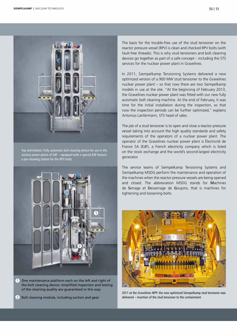
5150SieMpelkAMp | nUCLeAR teCHnoLoGy
One maintenance platform each on the left and right of the bolt cleaning device: simplified inspection and testing of the cleaning quality are guaranteed in this way
Top and bottom: Fully automatic bolt cleaning device for use in the nuclear power plants of EdF – equipped with a special EdF feature: a pre-cleaning station for the RPV bolts
Bolt cleaning module, including suction and gear
the basis for the trouble-free use of the stud tensioner on the reactor pressure vessel (RPV) is clean and checked RPV bolts (with fault-free threads). this is why stud tensioners and bolt cleaning devices go together as part of a safe concept – including the sts services for the nuclear power plant in Gravelines.
In 2011, siempelkamp tensioning systems delivered a new optimized version of a 900 MW stud tensioner to the Gravelines nuclear power plant – so that now there are two siempelkamp models in use at the site. “At the beginning of February 2013, the Gravelines nuclear power plant was fitted with our new fully automatic bolt cleaning machine. At the end of February, it was time for the initial installation during the inspection, so that now the inspection periods can be further optimized,” explains Antonius Lanfermann, sts head of sales.
the job of a stud tensioner is to open and close a reactor pressure vessel taking into account the high quality standards and safety requirements of the operators of a nuclear power plant. the operator of the Gravelines nuclear power plant is Électricité de France sA (edF), a French electricity company which is listed on the stock exchange and the world’s second-largest electricity generator.
the service teams of siempelkamp tensioning systems and siempelkamp MsDG perform the maintenance and operation of the machines when the reactor pressure vessels are being opened and closed. the abbreviation MsDG stands for Machines de Serrage et Desserrage de Goujons, that is machines for tightening and loosening bolts.
1
1
2
2
2011 at the Gravelines NPP: the new optimized Siempelkamp stud tensioner was delivered – insertion of the stud tensioner to the containment

SieMpelkAMp | nUCLeAR teCHnoLoGy
Development with expertise
the request to design and construct a multifunctional bolt cleaning machine came from the long-standing sts customer and partner edF. “the accumulated experience acquired from the global deployment of our service team went into the development of the bolt cleaning machine. together with a partner company we developed a closed cleaning machine to service the reactor pressure vessel bolts after the RPV had been opened and prepare them again for when the RPV is closed,” explains Antonius Lanfermann.
the prototype of the fully automatic RPV bolt cleaning machine was designed and constructed in such a way that it is possible to clean all RPV bolts of the different French reactor types. this requirement is fulfilled by installing the appropriate adapters and reading in the corresponding bolt/nut/cleaning parameters.
one reason for this multifunctional machine were the specifica-tions of the partner edF. the company received the prototype in 2011. since then, the new development has been “moving” back and forth between the edF power plants and is being successfully used in the various types of reactor. this multiple use has borne fruit: on the basis of the experience gained from the individual nuclear power plants, additional lifting accessories have been adapted in order to simplify handling to the deploy-ment location. Ultimately, the aim was to significantly shorten the cleaning times for the RPV bolts and RPV nuts and optimize the transport times.
Functionality test at the STS in Lünen, Germany: a bolt is placed into the cleaning head
Interior view of the cleaning head, equipped with six stainless steel wheel brushes for cleaning thethread sections of the bolt
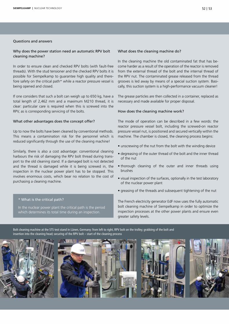
5352SieMpelkAMp | nUCLeAR teCHnoLoGy
What does the cleaning machine do?
In the cleaning machine the old contaminated fat that has be-come harder as a result of the operation of the reactor is removed from the external thread of the bolt and the internal thread of the RPV nut. the contaminated grease released from the thread grooves is led away by means of a special suction system. Basi-cally, this suction system is a high-performance vacuum cleaner!
the grease particles are then collected in a container, replaced as necessary and made available for proper disposal.
How does the cleaning machine work?
the mode of operation can be described in a few words: the reactor pressure vessel bolt, including the screwed-on reactor pressure vessel nut, is positioned and secured vertically within the machine. the chamber is closed, the cleaning process begins:
• unscrewing of the nut from the bolt with the winding device
• degreasing of the outer thread of the bolt and the inner thread of the nut
• thorough cleaning of the outer and inner threads using brushes
• visual inspection of the surfaces, optionally in the test laboratory of the nuclear power plant
• greasing of the threads and subsequent tightening of the nut
the French electricity generator edF now uses the fully automatic bolt cleaning machine of siempelkamp in order to optimize the inspection processes at the other power plants and ensure even greater safety levels.
Bolt cleaning machine at the STS test stand in Lünen, Germany: from left to right, RPV bolt on the trolley; grabbing of the bolt and insertion into the cleaning head; securing of the RPV bolt – start of the cleaning process
Questions and answers
Why does the power station need an automatic RPV bolt cleaning machine?
In order to ensure clean and checked RPV bolts (with fault-free threads). With the stud tensioner and the checked RPV bolts it is possible for siempelkamp to guarantee high quality and there-fore safety on the critical path* while a reactor pressure vessel is being opened and closed.
If one considers that such a bolt can weigh up to 650 kg, have a total length of 2,462 mm and a maximum M210 thread, it is clear: particular care is required when this is screwed into the RPV, as is corresponding servicing of the bolts.
What other advantages does the concept offer?
Up to now the bolts have been cleaned by conventional methods. this means a contamination risk for the personnel which is reduced significantly through the use of the cleaning machine!
similarly, there is also a cost advantage: conventional cleaning harbours the risk of damaging the RPV bolt thread during trans-port to the old cleaning stand. If a damaged bolt is not detected and the thread is damaged while it is being screwed in, the inspection in the nuclear power plant has to be stopped. this involves enormous costs, which bear no relation to the cost of purchasing a cleaning machine.
* What is the critical path?
In the nuclear power plant the critical path is the period which determines its total time during an inspection.

SieMpelkAMp | nUCLeAR teCHnoLoGy
Plasma hot wire cutting:
NIS Technical Center – a Siempelkamp competence location for process qualification during decommissioning
by Berthold Racky / Hermann-Josef Igelmund
Testing of the hot wire process: performing of various flame cuttings
For more than 20 years, the NIS Ingenieurgesellschaft is known as an established supplier of products and services for the safe
dismantling of nuclear facilities. Realistic tests are the prerequisites for the low-risk and efficient use of new processes and the
necessary equipment for the dismantling activities in Germany that will accrue in the near future. The NIS Technical Center in
Alzenau, Germany – newly established in spring 2011 – provides ideal conditions for experimental purposes and set-ups: a
facility to systematically analyze problems and challenges. It was the experiences of the NIS expert team gathered from the
successful disassembly of the Multi-purpose Research Reactor in Karlsruhe, Germany, the reactor pressure vessel (RPV) of the
Stade NPP in Germany and the ongoing project of disassembling the two RPVs at the ZION NPP in the USA, that led to the
decision in autumn 2012 to test a new thermal cutting process: the plasma hot wire cutting! The disassembly of highly acti-
vated steel internals like for example formwork tanks, measuring chambers, pipeworks etc. is being tested by courtesy of this
cutting process at our competence center in Alzenau. A qualification measure that brings Siempelkamp another step closer to
the market and customer needs in the area of decommissioning and dismantling.

5554SieMpelkAMp | nUCLeAR teCHnoLoGy
the specialists from nIs are important partners for the safe and effective dismantling of nuclear facilities, who thanks to their experience and skills in the field of thermal dismantling and remote handling are able to qualify a new process at the nIs technical Center in Alzenau, Germany.
In order to be forearmed for the future dismantling activities, the possible disassembly of an approximately 12 mm thick steel liner, which gives the biological shield its internal surface structure, is for example being tested. this has to be performed remotely owing to the high level of radioactivity. For this, nIs uses the manipulated technology of a converted industrial robot which has already been successfully used during the decommis-sioning of the reactor pressure vessel (RPV) in stade, Germany. the cutting technology is the “plasma hot wire” process of a well-known manufacturer of torch cutting equipment, which at the University of Hanover, Germany, under the direction of Prof. Dr.-Ing. habil. Friedrich-Wilhelm Bach has already demon-strated that it can be used in principle.
Is this suitable? “In principle it works,” say the nIs specialists, “but the devil is in the details”. the solution must work reliably in this very detail, as in the radiation field experimenting with a solution that has not been fully developed can result in inter-ruptions to operations. overcoming these would be associated with a good deal of time and expense.
The dismantling technique
For the dismantling (disassembly) of steel structures (formwork tank and steel installations in the concrete), the nIs is testing plasma cutting with and without the hot wire process as separation process. For the performance of the dismantling work, the plasma device technology is to be adapted to a carrier and manipulator system. this means that the device can move to the dismantling positions in the reactor shaft and the dismantling work can be carried out remotely with the use of video from the control station.
The redesign of the supporting frames and stabilization structures of the H2-recombiners has been successfully completed at the NIS Technical Center and convinced the Japanese customer TEPCO
NIS Technical Center:experimental tank and underwater test rig stand for remote
controlled dismantling

SieMpelkAMp | nUCLeAR teCHnoLoGy
Cutting processes for dismantling During the dismantling of nuclear power plants, cold cutting pro-cesses and thermal cutting processes are used for disassembling the reactor pressure vessel.
Cold cutting processes (amongst others):• Sawing • Milling • Drilling • High-pressure water jet cutting with abrasive agents
Thermal cutting processes (amongst others):• Oxy-fuel cutting • Plasma arc flame cutting • Plasma hot wire cutting
these methods have been used for reactor pressure vessel disas-sembly for approximately 15 years – also in combination with one another. Preconditions for the German nuclear power plants which are to be shut down by 2021 at the latest and the nuclear power plants to be shut down worldwide:
• reliable mastery of the dismantling processes • their use with remote handling devices and manipulators
Example: steel installations with marked positions of the reproduced test specimens
Realistic test specimens at the NIS Technical Center to test the hot wire cutting process
Manipulator in front of the flame cutting test section with steel wall specimen andconcrete background
Outline of the test facility at NIS Technical Center in Alzenau, Germany

SieMpelkAMp | nUCLeAR teCHnoLoGy
NIS Technical Center: process and equipment technology qualification
Within the framework of the qualification and specification of the proposed process and device technology, the manipulator-guided use of plasma-cutting is being tested at the nIs technical Center in Alzenau – with and without hot wire processes on realistic test specimens.
the manipulator is the industrial robot of the nIs technical Center. operation of the manipulator and the recording of teaching points for the calculation of the focal path for subsequent automatic shutdown is carried out by operating and teaching software developed by nIs. this has been specifically adapted to
5756
the boundary conditions for dismantling the steel installations. Besides the trials for specifying the device technology, the main aim of the team is to gather experience in handling the device technology and highlighting weaknesses or opportunities for improvements.
A further advantage is the carrying out of burning trials on realistic test specimens with and without a concrete background: they assist with the determination of the cutting parameters, such as the cutting speed, torch distance from the workpiece, gas pressures etc. as well as the determination of the optimum working angle of the torch during the dismantling of steel parts with a concrete background. Furthermore, cutting strategies are to be developed if possible with the aim of being able to success-fully carry out more complex cutting tasks.
The new thermal cutting process in the test rig
NIS Technical Center: testing of remote handling devices and cutting technologies under water and in air: equipment
• Underwater test stand including two pools of 4 m dia-
meter each and 2 m, i.e. 5 m water depth and related
water purification system
• Test section for flame cutting with welding fume suction
• Electric shop with measurement devices and power
sources for various measurement tasks and test con-
structions
• Machine shop for metalworking like sawing, drilling
and welding for the manufacture of test stand con-
structions and for the short-term adaptation and im-
provement of test objects
• The range of services is rounded off by i.a. a materials
store, a crane with fastening devices, industrial trucks,
winches, lifting devices, pumps and small tools
• Diverse radiation measurement systems for use in
control areas
• Training areas

SieMpelkAMp | nUCLeAR teCHnoLoGy
2 x compact knowledge
Radioactive radiation: In public discussions the terms “radioactivity” and “radiation” are often confused or used as synonyms. the term “radioactivity” is often used to refer not to the material, but to the radiation that is emitted – or even ionizing radiation from non-radioactive sources. Conversely, reports of incidents often speak of “leaked radiation” if they involve the unintentional leaking of radioactive substances. the frequently used term “radioactive radiation” is tautological, because “radioactive” already means “radiating”. What is meant here is the radiation of radioactive substances.
Biological shield: the reactor pressure vessel of a nuclear power plant is surrounded by a concrete structure which is approximately 2 m thick. the task of this structure is to provide a shield against the radiation from the reactor pres sure vessel in the same manner as a protective shield, that is a biological shield.
After determination of effective cutting parameters and led by the manipulator, cutting trials are carried out with the flame cutting head
Remote controlled positioning to the cutting points and implementation of the flame cuts with the use of video cameras at the NIS Technical Center
Examination of the flame cuttings
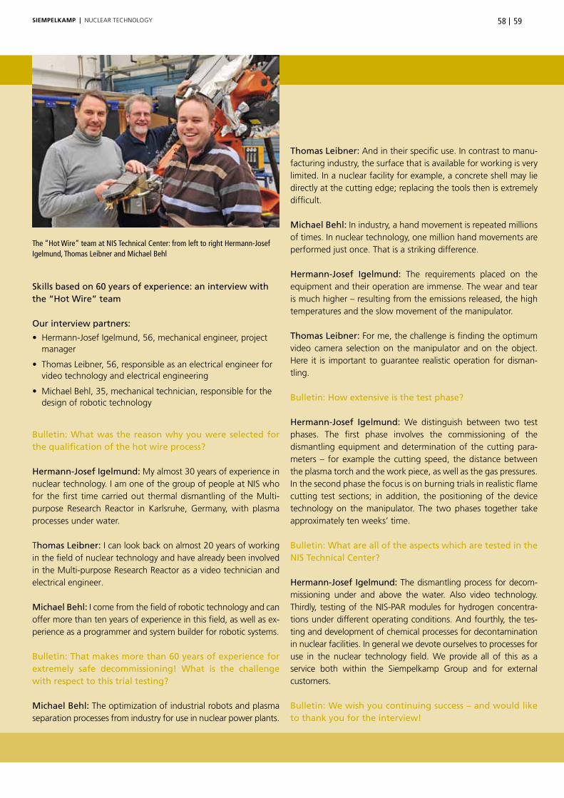
SieMpelkAMp | nUCLeAR teCHnoLoGy 5958
The “Hot Wire” team at NIS Technical Center: from left to right Hermann-Josef Igelmund, Thomas Leibner and Michael Behl
Skills based on 60 years of experience: an interview with the “Hot Wire” team
Our interview partners:
• Hermann-Josef Igelmund, 56, mechanical engineer, project manager
• Thomas Leibner, 56, responsible as an electrical engineer for video technology and electrical engineering
• Michael Behl, 35, mechanical technician, responsible for the design of robotic technology
Bulletin: What was the reason why you were selected for the qualification of the hot wire process?
Hermann-Josef Igelmund: My almost 30 years of experience in nuclear technology. I am one of the group of people at nIs who for the first time carried out thermal dismantling of the Multi-purpose Research Reactor in Karlsruhe, Germany, with plasma processes under water.
thomas Leibner: I can look back on almost 20 years of working in the field of nuclear technology and have already been involved in the Multi-purpose Research Reactor as a video technician and electrical engineer.
Michael Behl: I come from the field of robotic technology and can offer more than ten years of experience in this field, as well as ex-perience as a programmer and system builder for robotic systems.
Bulletin: That makes more than 60 years of experience for extremely safe decommissioning! What is the challenge with respect to this trial testing?
Michael Behl: the optimization of industrial robots and plasma separation processes from industry for use in nuclear power plants.
Thomas Leibner: And in their specific use. In contrast to manu-facturing industry, the surface that is available for working is very limited. In a nuclear facility for example, a concrete shell may lie directly at the cutting edge; replacing the tools then is extremely difficult.
Michael Behl: In industry, a hand movement is repeated millions of times. In nuclear technology, one million hand movements are performed just once. that is a striking difference.
Hermann-Josef Igelmund: the requirements placed on the equipment and their operation are immense. the wear and tear is much higher – resulting from the emissions released, the high temperatures and the slow movement of the manipulator.
Thomas Leibner: For me, the challenge is finding the optimum video camera selection on the manipulator and on the object. Here it is important to guarantee realistic operation for disman-tling.
Bulletin: How extensive is the test phase?
Hermann-Josef Igelmund: We distinguish between two test phases. the first phase involves the commissioning of the dismantling equipment and determination of the cutting para-meters – for example the cutting speed, the distance between the plasma torch and the work piece, as well as the gas pressures. In the second phase the focus is on burning trials in realistic flame cutting test sections; in addition, the positioning of the device technology on the manipulator. the two phases together take approximately ten weeks’ time.
Bulletin: What are all of the aspects which are tested in the NIS Technical Center?
Hermann-Josef Igelmund: the dismantling process for decom-missioning under and above the water. Also video technology. thirdly, testing of the nIs-PAR modules for hydrogen concentra-tions under different operating conditions. And fourthly, the tes-ting and development of chemical processes for decontamination in nuclear facilities. In general we devote ourselves to processes for use in the nuclear technology field. We provide all of this as a service both within the siempelkamp Group and for external customers. Bulletin: We wish you continuing success – and would like to thank you for the interview!

SieMpelkAMp | FoUnDRy
Cast components for the building materials industry:
A piece of Siempelkamp in every house!Building material suppliers play an important role for the Siempelkamp Giesserei. At the beginning of the 1980s, the
foundry gained a foothold in this business segment. The start was the production of press components with a unit
weight of up to 70 t for the lime sand brick industry – the status quo of which we are reporting on here!
by Helmut Rieck / Mathias Weil

SieMpelkAMp | FoUnDRy 6160
enquiries are sent to the siempelkamp raw material utilization and presses segment by customers who develop and market machines for the construction industry. In addition to mill components for the production of cement and clinker, we supply structural components for tile presses. the most prominent and most successful companies in this sector – Loesche GmbH, GeBR. PFeIFFeR se, thyssenKrupp Polysius AG, FLsmidth Inc. and sACMI IMoLA s.C. – are for many years sustainably convinced of the competence in thick-walled cast iron “made by siempelkamp” for the structural components of these systems. two example projects show how successful our cooperations are.
SACMI tile press production (photo: SACMI)
Building materials for house building,
produced with Siempelkamp cast
components:
• Cement
• Lime
• Gypsum
• Raw materials for ceramics
• Raw materials for clinker
• Tiles in their final form
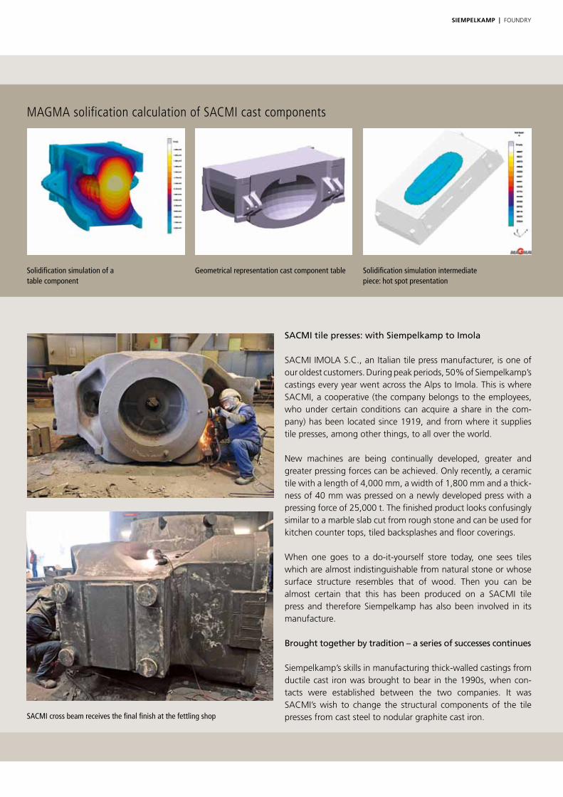
SieMpelkAMp | FoUnDRy
SACMI tile presses: with Siempelkamp to Imola
sACMI IMoLA s.C., an Italian tile press manufacturer, is one of our oldest customers. During peak periods, 50% of siempelkamp’s castings every year went across the Alps to Imola. this is where sACMI, a cooperative (the company belongs to the employees, who under certain conditions can acquire a share in the com-pany) has been located since 1919, and from where it supplies tile presses, among other things, to all over the world.
new machines are being continually developed, greater and greater pressing forces can be achieved. only recently, a ceramic tile with a length of 4,000 mm, a width of 1,800 mm and a thick-ness of 40 mm was pressed on a newly developed press with a pressing force of 25,000 t. the finished product looks confusingly similar to a marble slab cut from rough stone and can be used for kitchen counter tops, tiled backsplashes and floor coverings.
When one goes to a do-it-yourself store today, one sees tiles which are almost indistinguishable from natural stone or whose surface structure resembles that of wood. then you can be almost certain that this has been produced on a sACMI tile press and therefore siempelkamp has also been involved in its manufacture.
Brought together by tradition – a series of successes continues
siempelkamp’s skills in manufacturing thick-walled castings from ductile cast iron was brought to bear in the 1990s, when con-tacts were established between the two companies. It was sACMI’s wish to change the structural components of the tile presses from cast steel to nodular graphite cast iron.
Solidification simulation of atable component
SACMI cross beam receives the final finish at the fettling shop
MAGMA solification calculation of SACMI cast components
Geometrical representation cast component table Solidification simulation intermediatepiece: hot spot presentation

SieMpelkAMp | FoUnDRy 6362
the changeover from cast steel to nodular graphite cast iron – one of the trends in the foundry industry of the 1980s and 1990s – provided our customer with enormous competitive advantages. the lower weight and the reduced cost of procuring the structural components for the large presses provided sACMI with clear market advantages.
the changeover was overseen by our engineering department – and a lively exchange began on all technical levels. this also filled
Production of ceramic tiles Ceramic tiles are ceramic “plates” which are used as wall linings both indoors and outdoors, as well as for floor coverings.
Modern ceramic production uses the extrusion process and powder pressing (also called dry pressing). In the extrusion process, a plastic ceramic compound is ex-truded to form an endless band of single or double tiles (split clinker). this is then divided up into tiles of normal size.
In the dry pressing process, specially prepared ceramic powder is pressed in molds under high pressure and then fired. For its pressing systems, sACMI has recently made use of a comparable structure to siempelkamp’s ContiRoll®.
our order books in the 1990s. Recently – in september 2012 and January 2013 – sACMI commissioned new models such as cross-beams, cylinders, stands and tables.
It all began with a tile press crossbeam with a unit weight of ap-proximately 4.5 t. today, there are individual piece weights of up to 42 t. A tile press such as the PH6500 series with a pressing force of 6,500 t even includes up to 130 t of iron with six compo-nents made of nodular graphite cast iron.
Stable in every respect!
the quality is also appropriate and tested: only recently, sACMI presented the results of in-house tests of the cast iron part which had been carried out over several years with hollow drilled samples. the result: siempelkamp supplies components with the best mechanical characteristic values – and our quality contributes towards strengthening our long-standing partnership.
Advances in casting technology are also continuing at sACMI: our Italian customer researches into materials and the stress behavior of the components. there is also a trend becoming apparent here that cast iron parts are becoming increasingly efficient, their geometry more aesthetic and their weight is being reduced. Whereas the older design had the appearance of coarse and rectangular blocks, over the course of time – and also based on our suggestions – additional functions such as oil tanks for the hydraulic pipes were added to the shapes – and other potential savings achieved. We have repeatedly been able to support sACMI with our knowledge of casting and provide stimuli for optimizing the performance of materials and their geometry. An example: the component whose geometry has been optimized the most is a press cross beam for the latest model range. As a result of the curved design, it has above all been possible to save weight, so that the component now only weighs approximately 32 t and places the highest demands on our manufacturing tech-nology owing to its geometric complexity. every two to three weeks, a component of this size leaves the siempelkamp Giesserei. Per business year, twelve to 13 cast components therefore start out on their journey across the Alps to sACMI in Imola.
“In close cooperation with the engineers from sACMI, we see our work as the continuous optimization of our components in order to continuously improve them for the customers of our client sACMI. only recently, Matheo Cova, one of the designers at sACMI, praised the spirit of our collaboration,” explains Mathias Weil, sales engineer of the siempelkamp Giesserei.
From left to right: Helmut Rieck and Mathias Weil, the Siempelkamp experts for cast components used in the building materials industry

SieMpelkAMp | FoUnDRy
Diagram of a PFEIFFER vertical roller mill (photo: GEBR. PFEIFFER SE)
PFEIFFER vertical roller mill MVR 5600 C-4 for cement (photo: GEBR. PFEIFFER SE)
Cast component wing arm
Cast component grinding bowl
Siempelkamp and PFEIFFER – progress based on tradition
since the 1990s, a further cooperation has existed with the firm GeBR. PFeIFFeR se, a manufacturer of vertical mills. It all started with an interest in casting services for high individual piece weights. the trigger for the collaboration, which is still being continuously developed today, was an order 15 years ago for five 80 t grinding bowls to be supplied in quick succession for a customer in China. Here, we reliably implement a stringent schedule and supply chain, including mechanical processing.
Based on our common positive experience, it has been possible to continually expand the collaboration between PFeIFFeR and siempelkamp from 800 to 1,200 t of castings on a yearly basis. In 2012, more than 2,000 t of castings was produced from grinding bowls and plant components alone.
today, the large bowls have a diameter of up to 6,700 mm and a weight of more than 140 t, depending on their design – a “ball-
park figure” in comparison to previous dimensions. Here too, siempelkamp Maschinen- und Anlagenbau is able to repeatedly incorporate its machining and work hand-in-hand with the foundry. the foundry supplies the grinding bowls ready for in-stallation.
Pfeiffer has expanded its range to include MVR technology: the new MVR bowl mill crusher works with four to six roller modules, which are operated separately. MVR stands for mill, pendulum and roller, that is vertical roller mill. Maintenance or repair work can be carried out without interrupting ongoing operations. this reflects the continuing trend towards the larger and larger capa-cities of individual grinding systems – with major increases in the availability of the systems.
A further benefit: this technology guarantees much higher per-formance and better availability for the end customer. It has been possible to integrate the newly required attachment parts into the siempelkamp portfolio.

SieMpelkAMp | FoUnDRy 6564
Premiere at minus 40 °C
there have also been a number of innovations in the collaboration with PFeIFFeR: “together we have developed a flexible model standard whose application in this form has been unique over the past year. similarly, on the basis of the intense collaboration it has been possible to define concepts for the use of cement mills at extremely low ambient temperatures of minus 40 °C,” explains Helmut Rieck, long-standing sales engineer in the foundry.
to this purpose, siempelkamp have changed the alloy for the cast component material – a première! With the development of the MVR concept, PFeIFFeR have taken a giant step forward towards a significant improvement in grinding technology. For siempel-kamp, this innovation forms the basis for further successful colla-boration in the future.
Loading of a PFEIFFER grinding bowl
Casting of a 160 t grinding bowl

A short lesson in building materials
Cement: A hydraulic binding material that essentially consists of compounds of calcium oxide with silica, alumina and iron oxide, which are produced by sintering or smelting. When water is added, the finely ground material produces cement paste, which hardens both in the air and in water. Advantage: strength and volume stability under water.
SieMpelkAMp | FoUnDRy
Carousel machining of a grinding bowl in the maching center of Siempelkamp Maschinen- und Anlagenbau
Concrete: Cement to which water is added, as well as sand, gravel or crushed gravel produces concrete. Concrete can be produced as pumped, fair-faced, sprayed or insulating concrete. In the case of reinforced concrete, a distinction is made between steel, glass fiber and textile reinforcement, as well as pre-stressed concrete. the reinforcement means an increase in the supporting behavior in conjunction with concrete. the Frenchman Joseph Monier is considered to be the inventor of reinforced concrete. Pre-stressed concrete has existed in theory since 1886, but was first used after many approaches and attempts for the building of bridges in 1937.

Cement from antiquity to the present
Antiquity: it is not possible to determine when master builders used binding agents for construction for the first time. traces of lime mortar have been found in old structures in turkey which are more than 14,000 years old. Corresponding binding agents which even harden under water are also found in Mesopotamia, egypt and Phoenicia. From the period around 150 BC stem items of masonry in the Greek colonies in southern Italy in which two end wall (sound walls) are filled with a mixture of rubble, stone or mortar.
Roman period: the Romans developed the old knowledge even further. they were the first to work with concrete and produce foundations, parts of buildings, water pipes and harbor walls with it. the opus Caementitium (cement) was of high quality. A famous example is the Pantheon in Rome, which was started in 27 BC. the concrete dome has a diameter of 43 m and was only exceeded by structures with steel reinforcement such as the Centennial Hall in Breslau constructed by Max Berg in 1912, with a clear width of 65 m. the Romans fired the lime at a temperature of approximately 1000 °C.
Middle Ages: with the fall of the Roman empire, the knowledge of “opus caementitium” was lost. In many places the dominant construction method used a timber framework filled with willow rods, straw and loam. For the few houses made of stone, lime mortar that hardened in the air was used, although this was not water-resistant and therefore not permanent.
From the middle of the 17th century the Dutch used tuff from the eifel region to produce a mortar that hardened under water: trass. this quickly developed into a coveted trading item in other countries as well.
In the 18th century, the englishman J. smeaton invented Roman cement for the construction of the eddystone Lighthouse (today Roman lime).
In the 19th century (1824), the englishman Joseph Aspdin fired Portland cement, although the firing temperature had not yet reached the sintering point of 1450°C. nevertheless, this material was superior to Roman cement.
It was Isaac Charles Johnson who first realized the importance of firing at high temperatures in 1844 – after which e. Langer in Germany discovered the significance of adding blast furnace slag.
In the 20th century selected mixtures of raw materials and special grindings allow the production of cement with various properties: fast or slow-setting, high-strength or sulphate- resistant mixtures. It is even possible to produce a self-compacting concrete with cement if corresponding substances are added for aeration and vibration.
SieMpelkAMp | FoUnDRy 6766
Transport of a grinding bowl to the customer
Quality inspection of the wing arm cast component for use in cement mills
G. Siempelkamp GmbH & Co. KG
Siempelkamp Giesserei GmbH
Giesserei
Machines & Handling
W. Strothmann GmbH
Machines & Handling
CMC S.r.I.
Siempelkamp Giesserei Service GmbH
Giesserei Service
Foundry
Machinery and Plants Nuclear Technology
Sales companies/Representatives
Australia Siempelkamp Pty Ltd.
BrazilSiempelkamp do Brasil Ltda.
ChinaSiempelkamp (Wuxi) Machinery Manufacturing
Ltd., Beijing
FranceSiempelkamp France Sarl
IndiaSiempelkamp India Pvt. Ltd.
RussiaSiempelkamp Moscow
SingaporeSiempelkamp Pte Ltd.
SpainSiempelkamp Barcelona
TurkeySiempelkamp Istanbul
USASiempelkamp L.P.
Siempelkamp Nuclear Services Inc.
Nuclear Services
Siempelkamp Nuclear Technology Inc.
Nuclear Technology US
Siempelkamp Tensioning Systems GmbH
Tensioning Systems
Siempelkamp Nuclear Technology UK LTD.
Nuclear Technology UK
NIS Ingenieurgesellschaft mbH
NIS Ingenieurgesellschaft mbH
Siempelkamp MSDG S.A.S.
M S D G
Siempelkamp Nucléaire France S.A.S.
Nucléaire France
Siempelkamp Nukleartechnik GmbH
Nukleartechnik
Siempelkamp Prüf- und Gutachter-Gesellschaft mbH
Prüf- und Gutachter-Gesellschaft
Siempelkamp Krantechnik GmbH
All rights reserved. No part/parts of this publication may be reproduced, transmitted, edited or published in any form or by any means, electronic or mechanical, without the written permission from Siempelkamp Maschinen- und Anlagenbau GmbH & Co. KG © Siempelkamp Maschinen- und Anlagenbau GmbH & Co. KG
Siempelkamp Maschinenfabrik GmbH
Maschinenfabrik
Siempelkamp Maschinen- und Anlagenbau GmbH & Co. KG
Maschinen- und Anlagenbau
Hombak Maschinen- und Anlagenbau GmbH
Büttner Energie- und Trocknungstechnik GmbH
Ventilatoren – Apparatebau
Siempelkamp (Wuxi) Machinery Manufacturing Co. Ltd., China
Siempelkamp CZ s. r. o.
Siempelkamp Logistics & Service GmbH
ATR Industrie-Elektronik GmbH
Engineering
Sicoplan N.V.
Engineering
04.2
013/
3.60
0 G
B
G. Siempelkamp GmbH & Co. KG
Siempelkampstrasse 75 47803 Krefeld Germany
Phone: 02151/92-30 Fax: 02151/92-5604
www.siempelkamp.com