cylinders - albaalbaent.com/wp-content/uploads/2018/01/v250ce_catalog_v01b_web.pdf · velocidad del...
TRANSCRIPT

V25
0CE
www.vegacylinder.com
Short Stroke Block Cylinder With MagneticSwitches 250 Bar, Light Series
Cilindros hidráulicos carreras cortas con sensores magnéticos de fin de carrera 250 bares, serie ligera
Cat.V250CE.2012.00.GB+ES
®
Cylinders
V25
0CE
www.vegacylinder.com
Short Stroke Block Cylinder With MagneticSwitches 250 Bar, Light Series
Cilindros hidráulicos carreras cortas con sensores magnéticos de fin de carrera 250 bares, serie ligera
Cat.V250CE.2012.00.GB+ES
®
Cylinders
ContaCt For north ameriCan SaleS and teChniCal Support:
ph: 909.941.0600 • email: [email protected]
E2
V25
0CE
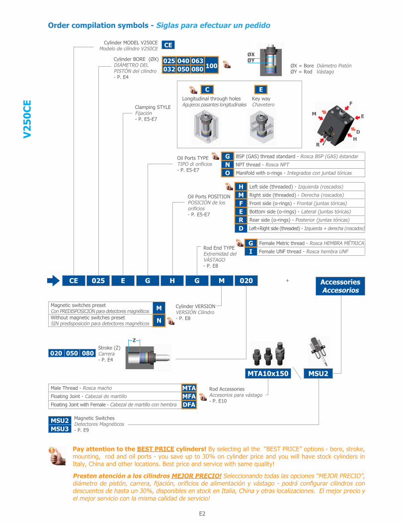
Order compilation symbols - Siglas para efectuar un pedido
Cylinder MODEL V250CEModelo de cilindro V250CE
Cylinder BORE (ØX)DIÁMETRO DEL PISTÓN del cilindro- P. E4
Clamping STYLEFijación - P. E5-E7
Oil Ports TYPETIPO di orificios- P. E5-E7
Oil Ports POSITIONPOSICIÓN de los orificios- P. E5-E7
Rod End TYPEExtremidad del VÁSTAGO- P. E8
Cylinder VERSIONVERSIÓN Cilindro- P. E8
Rod AccessoriesAccesorios para vástago- P. E10
Stroke (Z)Carrera- P. E4
Magnetic SwitchesDetectores Magnéticos- P. E9
Longitudinal through holesAgujeros pasantes longitudinales
Key wayChavetero
ØX = Bore Diámetro PistónØY = Rod Vástago
+
Pay attention to the BEST PRICE cylinders! By selecting all the “BEST PRICE” options - bore, stroke, mounting, rod and oil ports - you save up to 30% on cylinder price and you will have stock cylinders in Italy, China and other locations. Best price and service with same quality!
Presten atención a los cilindros MEJOR PRECIO! Seleccionando todas las opciones “MEJOR PRECIO”, diámetro de pistón, carrera, fijación, orificios de alimentación y vástago - podrá configurar cilindros con descuentos de hasta un 30%, disponibles en stock en Italia, China y otras localizaciones. El mejor precio y el mejor servicio con la misma calidad de servicio!
M
HD
E
F
R
Z
ØXØY025 040 063
100032 050 080
C
CE 025 E G H G M 020
MTA10x150 MSU2
AccessoriesAccesorios
MSU2MSU3
Male Thread - Rosca macho MTAFloating Joint - Cabezal de martillo MFAFloating Joint with Female - Cabezal de martillo con hembra DFA
G BSP (GAS) thread standard - Rosca BSP (GAS) éstandar
N NPT thread - Rosca NPT
O Manifold with o-rings - Integrados con juntad tóricas
H Left side (threaded) - Izquierda (roscados)
M Right side (threaded) - Derecha (roscados)
F Front side (o-rings) - Frontal (juntas tóricas)
E Bottom side (o-rings) - Lateral (juntas tóricas)
R Rear side (o-rings) - Posterior (juntas tóricas)
D Left+Right side (threaded) - Izquierda + derecha (roscados)
G Female Metric thread - Rosca HEMBRA MÉTRICA
I Female UNF thread - Rosca hembra UNF
CE
E
Magnetic switches preset Con PREDISPOSICIÓN para detectores magnéticos MWithout magnetic switches presetSIN predisposición para detectores magnéticos N
020 050 080

E2 E3
V25
0CE
Product presentation and general features Presentación del producto y características
Cylinder ACCESSORIES - ACCESORIOS del cilindro
The V250CE cylinders have been specially designed for being extremely compact and for applying the integrated end stroke MAGNETIC SWITCHES. Furthermore their construction permits a high standardization with consequent lower price and immediate delivery time. Available bores: from 25 mm to 100 mm and strokes 20, 50 and 80 mm. These cylinders are ideal for short stroke slides and cores on plastic injection moulds. Due to the light construction, the use of these cylinders for heavy duties is not recommended (for example for moving of extraction plates or for die casting moulds).
Los cilindros serie V250CE están concebidos para ser extremamente compactos y ser dotados de sensores magnéticos de fin de carrera. Su construcción permite una alta estandarización, con un resultado de un bajo precio y un plazo de entrega inmediato. Diámetros de pistón de 25 a 100 mm y carreras de 20, 50 y 80 mm. Estos cilindros son ideales en los moldes de inyección de plástico para mover postizos o correderas de carrera corta. La construcción ligera hace que no estén adaptos para aplicaciones pesadas en general (por ejemplo los moldes de inyección de aluminio). La construcción ligera hace que no estén adaptos para aplicaciones pesadas en general (por ejemplo los moldes de inyección de aluminio).
Special aluminum alloy piston, in two segments with syntherized magnet ring and PTFE+Carbographite seals with FKM Oring. Guide rings are in polyester resin for a high resistance and a long life.
Special aluminum alloy body for high pressure resistance and adapt for the magnetic switches.
Steel rod seals-cartridge with PTFE+ Carbographite seals with FKM O-ring. Guide rings are in polyester resin for a high resistance and a long life. This solution with separateseals lodging from the body simplifies the seals replacement.
End stroke magnetic switches, in option (the picture shows theexternal box. Switches are inside the cylinder). (see page E9).
Support key-way for foot clamping (See E13).
Chaveta de soporte para fijación en pie (ver E13).
Thermal insulating plate, ideal for high temperature applications. (See E12-13).
Chrome-plated steel rod, hardened and polished. Thickness of chromium plating 20 ųm and surface finish 0,4 ųm Ra, for a longer durability of the seals.
Unidirectional flow controller, to regulate the speed of the piston, and steel hydraulic pipe fittings for flow controller (see accessories catalogue).
Rod end accessories: male thread with locknut; floating joint with locknut and floating joint with female of the floating joint, for increasing the connection options between rod and slide.
Pistón en aleación de aluminio especial en dos partes con anillo magnético sinterizado. Juntas en PTFE + Carbo-Grafito y juntas tóricas en FKM, Segmentos de guiado en resina poliéster para una alta resistencia al degaste y una larga vida.
Vástago de acero cromado templado y revenido. Espesor del cromado 20 µm y acabado superficial 0,4 µm Ra que prolonga considerablemente la duración de las juntas.
Cartucho porta juntas del vástago en acero, con juntas en PTFE + Carbo-Grafito y juntas tóricas en FKM. Segmentos de guidado en resina poliéster para una alta resistencia al degaste y una larga vida. La solución del cartucho independiente facilita el cambio de juntas.
Cuerpo en aleación de aluminio especial para una alta resistencia a la presión y adaptado para la utilización de sensores magnéticos.
Regulador de caudal unidireccional para regular la velocidad del pistón y niples para accesorios hidráulicos (ver catalogo de accesorios)
Accesorios para el vástago: terminal roscado con contratuerca, cabezal de matillo con contratuerca y cabezal de martillo con hembra, para ofrecer más opciones de fijación entre el vástago y la pieza a mover.
Sensores magnéticos de fin de carrera, opcional (la imagen muestra solamente la parte visible al exterior del cilindro. Los sensores son inseridos en el cilindro. - ver página E9)
Placa termo aislante, para empleo con altas temperaturas (ver E12-13).

E4
V25
0CE
ØX ØY
8 MPa - 80 bar1160 PSI
10 MPa - 100 bar1450 PSI
12,5 MPa - 125 bar1812 PSI
16 MPa - 160 bar2320 PSI
20 MPa - 200 bar2900 PSI
ØXPush Pull Push Pull Push Pull Push Pull Push Pull
Empuje Tracción Empuje Tracción Empuje Tracción Empuje Tracción Empuje Tracción
025 18 393 189 491 236 613 295 785 378 981 473 25
032 22 643 339 804 424 1005 530 1286 678 1608 848 32
040 22 1005 701 1256 876 1570 1095 2010 1402 2512 1752 40
050 28 1570 1078 1963 1347 2453 1684 3140 2155 3925 2694 50
063 28 2493 2000 3116 2500 3895 3125 4985 4000 6231 5000 63
080 36 4019 3205 5024 4007 6280 5008 8038 6411 - - 80
100 45 6280 5008 7850 6260 9813 7825 12560 10017 - - 100
020 050 080
TECHNICAL AND WORKING CHARACTERISTICS ChartTabla de CARACTERISTICAS TECNICAS Y DE FUNCIONAMIENTO
Choice of BORE size and STROKE - Elección del DIAMETRO del PISTÓN y de la CARRERA
*: Oil delivery with manifold at higher pressure can bring oil leakages from oil delivery O-rings.*: El uso del cilindro con alimentación integrada a presión superior puede provocar perdida de aceite por las juntas tóricas de la alimentación.
Table PUSH and PULL FORCES in daN (1 daN = 1 Kgf)Tabla de la FUERZA de EMPUJE y de TRACCIÓN en daN(1 daN = 1Kgf)
STANDARD STROKES Table in mmTabla de CARRERAS ESTÁNDARES en mm
Example of order code:Ejemplo de código de pedido:
Note: Stroke tolerance: -0/+0,5 mm. For intermediate strokes choose the longer one and require the stroke reducer. Special strokes can be manufactured. Would you please contact our sales service.NOTA: Tolerancia de la carrera:-0/+0,5mm. Para carrera intermedia considerar la carrera inmediatamente superior o solicitar un reductor de carrera. Se pueden fabricar carreras especiales. Contacte con nuestro departamento de ventas.
ØX= Bore -Diámetro Pistón ØY= Rod - Vástago Z= Stroke -Carrera
ØX
ØY
Z
CE 025 E G H G M 020
ØX
Maximum Working PRESSURE in MPa - (bar) - PSIPRESION maxima de empleo en MPa (Bar)-PSI
Maximum Nominal delivery (pushing)
L/min
Maximum piston speed m/sec
Maximum working temperatureTemperatura máxima de trabajo
Manifold oil delivery*Alimentación con juntas tóricas*
Threaded oil deliveryOrificios roscados
Caudal Nominal Máximo (en empuje)
L/min
Velocidad máxima del pistón m/s
MAGNETIC CylinderCilindro MAGNÉTICO
NON magnetic CylinderCilindro NO magnético
25 16(160)-2320 25(250)-3625 1
0,05 80°C - 176° F 100°C - 212°F
32 16(160)-2320 25(250)-3625 2
40 14(140)-2030 25(250)-3625 3
50 14(140)-2030 25(250)-3625 5
63 12(120)-1740 20(200)-2900 10
80 12(120)-1740 18(180)-2610 15
100 12(120)-1740 18(180)-2610 20
STANDARD STROKESCARRERAS ESTÁNDARES
ØX Tightening torque NmPar de apreite Nm
25 24,6
32 45
40 45
50 80
63 80
80 150
100 150
Tightening torque for screws fixing the cylinder to the moldPar de apreite de los tornillos de fijación del cilindro sobre el molde

E4 E5
V25
0CE
Choice of CLAMPING style and OIL DELIVERYElección de la FIJACIÓN y de los ORIFICIOS DE ALIMENTACION
Key-way clamping with BSP (GAS) threaded oil delivery, LEFT sideFijación chaveta con orificios roscados BSP (GAS), lado IZQUIERDO
Key-way clamping with NPT threaded oil delivery, LEFT sideFijación chaveta con orificios roscados NPT, lado IZQUIERDO
#1 :- If this clamping style is adopted and oil pressure in the cylinder is higher than 160 bar = 2320 PSI, we advise to use a holding “wall” to avoid any deflection.#1 :- Si con esta fijación, se usa el cilindro a una presión más grande que 160 bares = 2320 PSI, se aconseja el uso de un soporte para evitar toda deformación.
Example of order code:Ejemplo de código de pedido:
Key-way clamping with BSP (GAS) threaded oil delivery, RIGHT sideFijación chaveta con orificios roscados BSP (GAS), lado DERECHO
Key-way clamping with NPT threaded oil delivery, RIGHT sideFijación chaveta con orificios roscados NPT, lado DERECHO
Stroke Carrera20mm
Stroke Carrera>= 50mm
CE 025 E G H G M 020
E G H
E N H
E G M
E N M
NOTE: All cylinders with BSP right side oil delivery and NPT left or right side oil delivery CAN HAVE A TIP ON THE SIDE OPPOSITE THE OIL DELIVERY.See measuring “T2” and ØT1 (see page P.E6)NOTA: Los cilindros con alimentación BSP lado derecho y NPT lado izquierdo o derecho PUEDEN TENER UN TAPÓN EN EL LADO OPUESTO A LA ALIMENTACIÓN. Ver la cuota “T2” y ØT1 (ver página P.E6)
ØX ØY Z T C+ A B F G H L M P ØQ ØQ1 R SH10 S1 ØSB
f8 V W WHNPT BSP
25 1820 -
57 65 45 30 50 9 12 22 1/4” 1/4” 8,5 13,5 50 10 2 32 6,5 37 1450 4080 70
32 2220 -
60 75 55 35 55 11 12 22 1/4” 1/4” 10,5 16,5 55 12 3 34 8 40 1550 4080 70
40 2220 -
73 85 63 40 63 11 14 24 1/4” 1/4” 10,5 16,5 63 12 3 34 7 43 1750 4580 75
50 2820 -
75 100 75 45 76 13 14,5 25 1/4” 1/4” 13 19 76 15 5 42 8 45 2050 4580 75
63 2820 -
85 115 90 55 90 13 21 29 3/8” 3/8” 13 19 90 15 5 50 7 55 2050 4080 70
80 3620 -
100 140 110 75 110 17 25 35 1/2” 1/2” 17 25 110 20 5 60 7 60 2050 40- -
100 4520 -
110 170 140 95 135 17 28 37 1/2” 1/2” 17 25 135 20 5 72 8 70 2550 30- -
ØX = Bore Diámetro Pistón ØY = Rod Vástago Z = Stroke Carrera (P.E4) eg. ØX = 25 , ØY = 18, Z = 20mm : C + Z = 57 + 20 = 77 mm
NOTE: For dimensions where no tolerance is indicated, refer to DIN norm 7168-mNOTA: Para las dimensiones sin tolerancia, referirse a la norma DIN 7168-m

E6
V25
0CE
Choice of CLAMPING style and OIL DELIVERYElección de la FIJACIÓN y de los ORIFICIOS DE ALIMENTACION
Key-way clamping with BSP (GAS) threaded double oil delivery, LEFT + RIGHT sideFijación chaveta con orificios roscados BSP (GAS), lado IZQUIERDO + DERECHO
Key-way clamping with NPT threaded double oil delivery, LEFT + RIGHT sideFijación chaveta con orificios roscados NPT, lado IZQUIERDO + DERECHO
#2 :- Warning: Caps (T2) protrude on the left or on the right side. Max. eccentricity mm 0,5 - O-rings included in the supply.#2 :- Atención: Tapos sobresalidos (T2) en el lado izquierdo o derecho. Excentricidad máx. 0,5 mm - Juntas tóricas están incluidas en el suministro.
Example of order code:Ejemplo de código de pedido:
Key-way clamping with BOTTOM manifold oil deliveryFijación chaveta con alimentación integrada LATERAL
Stroke Carrera20mm
Stroke Carrera>= 50mm
CE 025 E G D G M 020
E G D
E N D
E O E
ØX ØY C + A B ØD N O ØT1 T2
25 18 57 65 45 10 22 7 19 5
32 22 60 75 55 10 22 7 19 5
40 22 73 85 63 10 24 10 19 5
50 28 75 100 75 10 25 10 19 5
63 28 85 115 90 13 29 15 22 5
80 36 100 140 110 13 35 17 27 5
100 45 110 170 140 13 37 20 27 5
ØX = Bore Diámetro Pistón ØY = Rod Vástago Z = Stroke Carrera (P.E4) eg. ØX = 25 , ØY = 18, Z = 20mm : C + Z = 57 + 20 = 77 mm
NOTE: For dimensions where no tolerance is indicated, refer to DIN norm 7168-mNOTA: Para las dimensiones sin tolerancia, referirse a la norma DIN 7168-m

E6 E7
V25
0CE
Choice of CLAMPING style and OIL DELIVERYElección de la FIJACIÓN y de los ORIFICIOS DE ALIMENTACION
Longitudinal through holes with FRONTAL manifold oil deliveryAgujeros pasantes longitudinales con alimentación integrada FRONTAL
#3 :- Max. diameter of oil delivery hole in the plate: 3 mm (Cylinders ø25÷50) and 5 mm (Cylinders ø63÷100). Max. eccentricity mm 0,5 - O-rings included in the supply.#3 :- Diámetro máx. del agujero de alimentación de la placa: 3 mm (cilindros Ø 25÷50) y 5 mm (cilindros Ø 63-100). Excentricidad máx. 0,5 mm. Juntas tóricas incluidas en el suministro.
Example of order code:Ejemplo de código de pedido:
Longitudinal through holes with REAR manifold oil deliveryAgujeros pasantes longitudinales con alimentación integrada POSTERIOR
CE 025 C O F G M 020
C O F
C O R
ØX ØY C + A B ØD E K
25 18 57 65 45 10 51 25,5
32 22 60 75 55 10 60 30
40 22 73 85 63 10 65 32,5
50 28 75 100 75 10 80 40
63 28 85 115 90 13 95 47,5
80 36 100 140 110 13 118 59
100 45 110 170 140 13 140 70
ØX = Bore Diámetro Pistón ØY = Rod Vástago Z = Stroke Carrera (P.E4) eg. ØX = 25 , ØY = 18, Z = 20mm : C + Z = 57 + 20 = 77 mm
NOTE: For dimensions where no tolerance is indicated, refer to DIN norm 7168-mNOTA: Para las dimensiones sin tolerancia, referirse a la norma DIN 7168-m

E8
V25
0CE
Choice of Rod End Style - Determinación de la extremidad del vástago
Example of order code:Ejemplo de código de pedido:
ØX = Bore Diámetro Pistón ØY = Rod Vástago
Choice of cylinder VERSION - Determinación de la VERSIÓN del cilindro
Example of order code:Ejemplo de código de pedido:
CE 025 E G H G M 020
DESCRIPTION OF ROD END STYLESDESCRIPCIÓN TIPO DE EXTREMIDAD
METRIC FEMALE thread - STANDARDRosca HEMBRA MÉTRICA - ESTANDAR GUNF-UNEF female thread (U.S.A. Standard)Rosca HEMBRA UNF-UNEF (Estándar U.S.A.) I
CE 025 E G H G M 020
CYLINDER VERSIONVERSIÓN DEL CILINDRO
Magnetic switches preset CON PREDISPOSICIÓN para sensores magnéticos MWithout magnetic switches presetSIN predisposición para sensores magnéticos N
ØX ØYC
D E ØM P V WH METRIC UNF
25 18 M10×1,5 3/8-24 20 6 17 15 6,5 14
32 22 M12×1,75 1/2-20 20 5,5 21 18 8 15
40 22 M14×2 9/16-18 20 5,5 21 18 7 17
50 28 M20×2,5 3/4-16 30 8 27 24 8 20
63 28 M20×2,5 3/4-16 30 8 27 24 7 20
80 36 M27×3 1-12 40 11 35 32 7 20
100 45 M33×3,5 1-1/4-12 50 12 44 40 8 25
SWITCHES TO BE ORDERED SEPARATELY FROM THE CYLINDER.LOS SENSORES MAGNETICOS DEBEN SER PEDIDOS SEPARADAMENTE AL CILINDRO.
NOTE: For dimensions where no tolerance is indicated, refer to DIN norm 7168-mNOTA: Para las dimensiones sin tolerancia, referirse a la norma DIN 7168-m

E8 E9
V25
0CE
ACCESSORIES - ACCESORIOSMagnetic Switches - Sensores magnéticos
Example of order code:Ejemplo de código de pedido:
Wire Colour Color de los cablesBrown Marrón = +24V DCBlue Azul marino = 0V DCBlack Negro = In/Out Contact Contacto entrada/salida (Position de retour - Zurück Position)White Blanco = In/Out Contact Contacto entrada/salida (Position de retour - Zurück Position)
I/U = In/Out entrada/salida
+24V I/U I/U 0V
MSU2 Switches Technical Data MSU2/3Datos Técnicos de los sensores MSU2/3
Supply - Entrada de aceite 24 VDC ± 10% Protection - Protección polarity inversion - inversión de polaridad Output - Tipo de señal clean contact 0V - contacto limpio 0V Max. switching voltage - Tensión máx. de conmutación 125V AC Max. switching current - Corriente máx. de conmutación 800 mA Max. switching frequency - Frecuencia máx de commutación 60 Hz Max. switching power - Potencia máx. de conmutación 30W Electric life at rated power (operations) - Vida eléctrica 10,000,000 Hysteresis - Histéresis ±0,02 mm typical - ±0,02 mm tipico 24 volt disconnection delay - Retraso a la desconexión a 24 V 15 ms Max. working temperature - Temperatura máxima de trabajo +80° C - +176° F Cable (Extraflex armoured + transp. PVC sheath) Cable blindado extraflex. PVC externo transparente Ø6 x 3000
Section wires - Sección de los hilos 6x0,14 mm2 Serial signal connection - Conexión de la señal en serie ok, max 6 switches - si, max. 6 sensores
Switch type - Tipo de interruptores electronic, magnet-resistive eléctronico magnétosensitivo
Repeatability - Repetibilidad > 0,05 mm ON minimum time - Tiempo minimo en ON 3 ms Max. flow speed - Velocidad de paso máx. 15 m/s Degree of protection - Grado de protección IP 67 (DIN 40050)
Dimensions - Dimensiones en mm 46x45,5x10,5
ØX ØY Z
25 1820 MSU250 MSU280 MSU3
32 2220 MSU250 MSU280 MSU3
40 2220 MSU250 MSU380 MSU3
50 2820 MSU250 MSU380 MSU3
63 2820 MSU350 MSU380 MSU3
80 3620 MSU350 MSU3- -
100 4520 MSU350 MSU3- -
ØX ØY Z SC SD SE SA SF I J
25 1820 27,5 - -
28 20 3 850 30 35 3080 60 35 30
32 2220 35 - -
30 20 3 850 40 30 3080 70 30 30
40 2220 50 - -
36 20 3 850 50 30 3080 80 30 30
50 2820 50 - -
42 20 3 850 50 30 3080 80 30 30
63 2820 60 - -
56 30 3 850 60 30 3080 90 30 40
80 3620 70 - -
65 33 3 850 70 37 30- - - -
100 4520 77 - -
56 47 3 850 77 30 30- - - -
NOTES: In order to avoid any possible magnetic distortion, the application of the cylinders with magnetic switches inside iron masses (e.g. moulds) needs proper distance (min. 25 mm) between the body of the cylinder and the external iron mass, except for the clamping side.
NOTA: Para evitar posibles distorsiones magnéticas durante la aplicación de cilindros con sensores magnéticos dentro de las masas metálicas (por ejemplo dentro del molde) se necesita una distancia mínima de 25mm entre el cuerpo del cilindro y las masas metálicas, a excepción del lado de la fijación.
ØX = Bore Diámetro Pistón ØY = Rod Vástago Z = Stroke Carrera
SWITCHES POSITION REGULATION: Extended rod position: insert the relevant switch into its seat and slide it to the end; from there, slowly move it to the oppo-site direction until the led is on. Move it of approx. one mm more in the same direction and fix it with the relevant screw. Retracted rod position: slowly insert the switch into its seat and slide it to the end. Move it of approx. one mm more in the same direction and fix it with the relevant screw. A proper REED CONTROLLER is available for the switch test. See accessory catalogue.
REGULACION DE LA POSICION DE LOS SENSORES: Con el vástago fuera: inserir el sensor correspondiente hasta el fondo de su alojamiento; de esta posición arrastrarlo lentamente atrás hasta la señal. Moverlo de 1 mm más hacia atrás y bloquearlo. Con el vástago dentro: inserir lentamente el sensor en su lugar y deslizarlo hasta la señal. desplazarlo de 1 un mm más en la misma dirección y fijarlo. Para probar los sensores, se dispone de un REED CONTROLLER. Ver accesorios en el catalogo.

E10
V25
0CE
ACCESSORIES - ACCESORIOSRod accessories for rod Metric or UNF threadACCESORIOS DEL VÁSTAGO para extremidad roscada HEMBRA Métrica o UNF
Example of order code:Ejemplo de código de pedido:
Metric MaleThreadRosca macho métrica
Floating JointCabezal de martillo
Floating Joint WithFemaleCabeza de martillo macho y hembra
MTA 10X150
M T A
M F A
D F A
METRIC (G) UNF-UNEF (I) ØX ØY #1
10X150 3/8- 24 25 18 G I
12X175 1/2-20 32 22 G I
14X200 9/16-18 40 22 G I
20X250 3/4-16 50 28 G I
20X250 3/4-16 63 28 G I
27X300 1-12 80 36 G I
33X350 1-1/4-12 100 45 G I
#1 : Compatible rod end code Cod. extremidad de vástago compatible
METRIC UNF-UNEF A B C D E F G H FA FB FC FE FF FG TA TB
M W U V
10X150 3/8-24 M10×1,5 M10×1,25 3/8-24 3/8-24 17,5 11 11 8 16 12,5 21 25 16 10 7 6 17 24 14 44
12X175 1/2-20 M12×1,75 M12×1,25 1/2-20 1/2-20 19,5 12 13 9 18 14,5 24 28 18 11 8 7 19 28 16 51
14X200 9/16-18 M14×2 M14×1,5 9/16-18 9/16-18 19,5 12 13 9 22 14,5 24 28 18 11 8 8 22 33 18 59
20X250 3/4-16 M20×2,5 M20×1,5 3/4-16 3/4-16 24 15 16 10 28 17,5 30 36 22 14 10 9 30 39 28 76
27X300 1-12 M27×3 M27×2 1-12 1-12 30 19 20 12 40 23 36 44 28 18 12,5 12 36 52 36 100
33X350 1-1/4-12 M33×3,5 M33×2 1-1/4-12 1-5/16-18 39 23 26 14 50 27,5 46 55 35 22 16 14 46 64 45 123
NOTE: For dimensions where no tolerance is indicated, refer to DIN norm 7168-mNOTA: Para las dimensiones sin tolerancia, referirse a la norma DIN 7168-m
E10 E11
V25
0CE
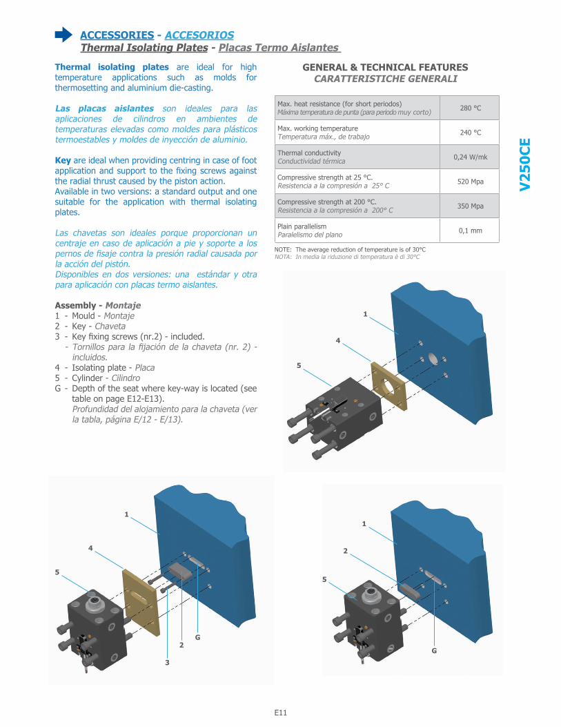
ACCESSORIES - ACCESORIOSThermal Isolating Plates - Placas Termo Aislantes
Thermal isolating plates are ideal for high temperature applications such as molds for thermosetting and aluminium die-casting.
Las placas aislantes son ideales para las aplicaciones de cilindros en ambientes de temperaturas elevadas como moldes para plásticos termoestables y moldes de inyección de aluminio.
Key are ideal when providing centring in case of foot application and support to the fixing screws against the radial thrust caused by the piston action.Available in two versions: a standard output and one suitable for the application with thermal isolating plates.
Las chavetas son ideales porque proporcionan un centraje en caso de aplicación a pie y soporte a los pernos de fisaje contra la presión radial causada por la acción del pistón.Disponibles en dos versiones: una estándar y otra para aplicación con placas termo aislantes.
Assembly - Montaje1 - Mould - Montaje2 - Key - Chaveta3 - Key fixing screws (nr.2) - included. - Tornillos para la fijación de la chaveta (nr. 2) -
incluidos.4 - Isolating plate - Placa5 - Cylinder - CilindroG - Depth of the seat where key-way is located (see
table on page E12-E13). Profundidad del alojamiento para la chaveta (ver la tabla, página E/12 - E/13).
GENERAL & TECHNICAL FEATURES CARATTERISTICHE GENERALI
1
4
5
1
2
5
G
1
4
5
G2
3
Max. heat resistance (for short periodos) Máxima temperatura de punta (para periodo muy corto) 280 °C
Max. working temperature Temperatura máx., de trabajo 240 °C
Thermal conductivity Conductividad térmica 0,24 W/mk
Compressive strength at 25 °C. Resistencia a la compresión a 25° C 520 Mpa
Compressive strength at 200 °C. Resistencia a la compresión a 200° C 350 Mpa
Plain parallelism Paralelismo del plano 0,1 mm
NOTE: The average reduction of temperature is of 30°CNOTA: In media la riduzione di temperatura è di 30°C

E12
V25
0CE
ACCESSORIES - ACCESORIOS
Example of order code:Ejemplo de código de pedido:
Lateral thermal isolating plate - Placa termo aislante lateral
Stroke Carrera20mm
Stroke Carrera>= 50mm
025REBIP 020
G : Dimension of the seat depth for the key-way on the mould. Support key and screws are included. Cuota correspondiente a la profundidad del alojamiento para la chaveta en el molde. La chaveta de soporte y los tornillos están incluidos.
ØX ØY
025 25 18
032 32 22
040 40 22
050 50 28
063 63 28
080 80 36
100 100 45
StrokeCarrera
(Z)
000
ØX ØY Z B C E G H I J L M+ N P R S T ØU ØV ØW
25 1820
35 15 10 3 25 10 10 37 56 50 64 M4 5-
8,5 4,5 7,550 4080 70
32 2220
40 18 10 5 28 12 12 40 59 55 74 M5 6-
10,5 5,5 950 4080 70
40 2220
45 18 10 5 33 12 12 43 72 63 84 M5 6-
10,5 5,5 950 4580 75
50 2820
55 22 10 7 40 15 15 45 74 76 99 M6 7-
13 6,5 10,550 4580 75
63 2820
70 22 10 7 55 15 15 55 84 90 114 M6 7-
13 6,5 10,550 4080 70
80 3620
80 22 10 7 60 20 20 60 99 110 139 M10 11-
17 10,5 16,550 40- -
100 4520
110 22 10 7 90 20 20 70 109 135 169 M10 11-
17 10,5 16,550 30- -
ØX = Bore Diámetro Pistón ØY = Rod Vástago Z = Stroke Carrera
- 0,10 - 0,20
+ 0 - 0,03
NOTE: For dimensions where no tolerance is indicated, refer to DIN norm 7168-mNOTA: Para las dimensiones sin tolerancia, referirse a la norma DIN 7168-m

E12 E13
V25
0CE
ACCESSORIES - ACCESORIOS
Example of order code:Ejemplo de código de pedido:
Frontal thermal isolating plate - Placa termo aislante frontal
Key for lateral mounting - Chaveta para fijación lateral
Example of order code:Ejemplo de código de pedido:
G : Dimension of the seat depth for the key-way on the mould. Cuota correspondiente a la profundidad del alojamiento para la chaveta en el molde.
NOTE: Not available with frontal oil delivery « F »NOTA: No disponible con alimentación frontal « F »
025REFIP ØX ØY
025 25 18
032 32 22
040 40 22
050 50 28
063 63 28
080 80 36
100 100 45
025REKW
ØX ØY B G I K
25 18 35 3 10 5
32 22 40 5 12 8
40 22 45 5 12 8
50 28 55 7 15 12
63 28 70 7 15 12
80 36 80 7 20 12
100 45 110 7 20 12
ØX ØY A D E F G ØR ØU
25 18 64 10 44 30 50 32 8,5
32 22 74 10 54 35 55 34 10,5
40 22 84 10 62 40 63 34 10,5
50 28 99 10 74 45 76 42 13
63 28 114 10 89 55 90 50 13
80 36 139 10 109 75 110 60 17
100 45 169 10 139 95 135 72 17
ØX ØY
025 25 18
032 32 22
040 40 22
050 50 28
063 63 28
080 80 36
100 100 45
- 0,10 - 0,20
+ 0 - 0,03
ØX = Bore Diámetro Pistón ØY = Rod Vástago Z = Stroke Carrera
NOTE: For dimensions where no tolerance is indicated, refer to DIN norm 7168-mNOTA: Para las dimensiones sin tolerancia, referirse a la norma DIN 7168-m
NOTE: For dimensions where no tolerance is indicated, refer to DIN norm 7168-mNOTA: Para las dimensiones sin tolerancia, referirse a la norma DIN 7168-m

E14
V25
0CE
Example of order code:Ejemplo de código de pedido:
Type
Mod
elo
Cylin
der
bore
Diám
etro
del
pist
ón
Artic
le C
ode
Códi
go a
rtíc
ulo
Cylin
der
stro
keCa
rrer
a de
l cili
ndro
Addi
tiona
l set
cod
eG
rupo
de
códi
gos
adic
iona
les
1
23
4
5
9 8 7 6
RE … 6010 A Rod seals kit - Juego de juntas del vástago 6
RE … 6020 A Piston seals kit - Juego de juntas del pistón 3
RE … 6030 FKM o-ring for integrated oil delivery - Juntas tóricas in FKM para entrada de aceite integrada
RE … 0310 Rod cartridge without seals - Cartucho del vástago sin juntas 5
RE … 0310 A Rod cartridge with seals - Cartucho del vástago con juntas 5+6
RE … 6050 Permament Magnet Ring - Imán permanente 8
RE … 1520 A Non magnetic piston with seals - Pistón no magnético con juntas 3+4
RE … 1510 A Magnetic piston with seals - Pistón magnético con juntas 3+4+8
RE … 1120 … Rod with Female Metric Thread Rod End “G” - Vástago con extremidad con rosca métrica “G” 7
RE … 1121 … Rod with Female UNF Thread Rod End “I” - Vástago con extremidad con rosca UNF “I” 7
RE … 1530 A … Magnetic rod-piston group with Female Metric Thread Rod End “G” Conjunto vástago / pistón magnético con extremidad con rosca métrica “G” 3+4+7+8
RE … 1531 A … Magnetic rod-piston group with Female UNF Thread Rod End (USA Standard) “I” Conjunto vástago / pistón magnético con extremidad con rosca UNF (Estándar U.S.A.) “I” 3+4+7+8
RE … 1540 A … Non-magnetic rod-piston group with Female Metric Thread Rod End “G” Conjunto vástago / pistón normal con extremidad con rosca métrica “G” 3+4+7
RE … 1541 A … Non-magnetic rod-piston group with Female UNF Thread Rod End (USA Standard) “I” Conjunto vástago / pistón normal con extremidad con rosca UNF (Estándar U.S.A.) “I” 3+4+7
RE … 1930F … Body for clamping style “C”, frontal oil ports with O-Rings - Cuerpo con fijación “C”, orificios con juntas tóricas frontales
9
RE … 1930R … Body for clamping style “C”, back oil ports with O-Rings - Cuerpo con fijación “C”, orificios con juntas tóricas posteriores
RE … 1920M … Body for clamping style “E”, BSP right-positioned threaded holes - Cuerpo con fijación “E”, orificios roscados BSP lado derecho
RE … 1920H … Body for clamping style “E”, BSP left-positioned threaded holes - Cuerpo con fijación “E”, orificios roscados BSP lado izquierdo
RE … 1924M … Body for clamping style “E”, NPT right-positioned threaded holes - Cuerpo con fijación “E”, orificios roscados NPT lado derecho
RE … 1924H … Body for clamping style “E”, NPT left-positioned threaded holes - Cuerpo con fijación “E”, orificios roscados NPT lado izquierdo
RE … 1934E … Body for clamping style “E”, lateral oil ports with O-Ring - Cuerpo con fijación “E”, orificios con juntas tóricas laterales
RE … 1920D … Body for clamping style “E”, BSP right and left-positioned threaded holes Cuerpo con fijación « E », orificios roscados BSP lado derecho y izquierdo
RE … 1924D … Body for clamping style “E”, NPT right and left-positioned threaded holes Cuerpo con fijación « E », orificios roscados NPT lado derecho y izquierdo
RE … 6301 A … Fixing Switch Screw, each cylinder requires two of them Tornillos de fijación del sensor, cada cilindro necesita dos 2
MSU2 Multifunction switch - Sensor completo1
MSU3 Multifunction switch -Sensor completo
RE 025 6010 A
1 Double Magnetic Switch Doble sensor magnético2 Fixing Switch Screw, each cylinder requires two of them Tornillos de fijación del sensor, cada
cilindro necesita dos3 Piston seals - Juntas del pistón4 Piston - Pistón5 Rod Cartridge Cartucho porta juntas del vástago6 Rod seals - Juntas del vástago7 Rod - Vástago8 Magnet Ring, for magnetic cylinder Anillo magnético, para cilindro magnético9 Body - Cuerpo
Spare Parts - Recambios

E14 E15
V25
0CE
Notes Nota

®
www.vegacylinder.com
alba enteRPRISeS, llC2730 monterey Street Suite 103, torrance, Ca 90503
ph: 909.941.0600 • 800.432.6653 • FX: 909.941.0190
email: [email protected] • www.albaent.com
ContaCt FoR noRth ameRICan SaleS and teChnICal SuPPoRt