d3.4 definition and development of kbe- · pdf filed3.4 – definition and development of...
TRANSCRIPT
Copyright Manutelligence Consortium 2015-2018 Manutelligence N°636951
Horizon 2020
Acronym: Manutelligence
Project No: 636951
Call: H2020-FoF-2014
Topic: FoF-05- Innovative product-service design using manufacturing intelligence
Type of action: RIA
Duration: 01.02.2015 - 31.01.2018
D3.4 – Definition and Development of KBE-systems
Type Deliverable
Document ID: D3.4
Workpackage: 3
Leading partner: BIBA
Author(s): Patrick Klein
Dissemination level: Public
Status: Released
Date: 25.01.2017
Version: 1.0

Public
Copyright Manutelligence Consortium 2015-2018 Page 2 / 34
Versioning and contribution history
Version Description Contributors
0.1 Initial draft and Structure BIBA
0.2 – 0.6 Draft in progress filled with content BIBA
0.7 Final draft before internal review BIBA
0.8 Draft including review comments and improvements SUPSI
0.9 Updated draft BIBA
1.0 Final version – to be submitted to EC BIBA
Reviewers
Name Affiliation
Donatella Corti SUPSI
Deliverable Peer Review Summary
ID Comments Addressed ()
Answered (A)
1
Some minor comments and typos,
two pictures (5 & 7) not visible for
reviewer (all notifications have been
placed in v0.8 of document)
All addressed in v1.0 ()
Public
Copyright Manutelligence Consortium 2015-2018 Page 3 / 34
Table of Contents
1 Introduction and scope of this deliverable ................................................................. 5
1.1 Research approach ........................................................................................................ 6
2 Introduction to Knowledge Based Engineering (KBE) .................................................. 7
2.1 Analysis of the 3DS embedded KBE approach provided by CATIA .................................... 9
3 SysML extension to define KbeML ........................................................................... 14
3.1 Enhancement to Product Service Life-Cycles ................................................................. 17
3.2 Adaption and Enhancement to Services/ Product configurators .................................... 19
4 Relation to LifeCycle modelling & LML ..................................................................... 20
4.1 Sample Case - Thermal insulation ................................................................................. 23
5 Enhancement of the Semantic Facilitator Domain ontology ..................................... 27
6 Interfaces to current knowledge bases .................................................................... 29
7 Summary and conclusions ....................................................................................... 32
8 References .............................................................................................................. 33

Public
Copyright Manutelligence Consortium 2015-2018 Page 4 / 34
Figures
Figure 1: Lead-time reduction of KBE solutions in industry (Vermeulen, 2007) ................................................... 7
Figure 2: The Knowledgeware workbench (of CATIA V5) embedding KBE capabilities into CAD .................... 9
Figure 3: Relation between UML, SysML and KbeML........................................................................................ 14
Figure 4: From UML to SysML to a KbeML extension ....................................................................................... 15
Figure 5: Graphical representation in Life-Cycle Modelling Language ............................................................... 20
Figure 6: Newton formula applied to Car ............................................................................................................. 22
Figure 7 Representation of the insulation in LML ................................................................................................ 23
Figure 8: Prefab wall with structural and non-structural sections (Lindbäcks) ..................................................... 24
Figure 9: Thermal insulation in conjunction with structural components ............................................................. 25
Figure 10: Prefab-Wall U_Value Calculation ....................................................................................................... 26
Figure 11: Enhancement of Semantic Facilitator Domain ontology with KbeML elements ................................ 28
Figure 12: Parameter mapping between KbeML model and commercial CAx application (shema) .................... 31
Tables
Table 1: Samples KBE using Knowledgeware workbench of CATIA (3DS component) .................................... 10
Table 2: KbeML Elements defined as an extension of SysML Metaclasses ......................................................... 15
Table 3: Addditional KbeML elements referent to information from the product usage phase ............................ 18
Table 4: KbeML Enhancement to Services/ Product configurators ...................................................................... 19
Table 5: Interdependecies between LML SysML & KbeML................................................................................ 21
Table 6: Relations between concepts of Domain ontology and concepts representing KbeML .......................... 28
Table 7: XMI-file of a KbeML model with highlighted element identifiers ......................................................... 30

Public
Copyright Manutelligence Consortium 2015-2018 Page 5 / 34
1 Introduction and scope of this deliverable
This deliverable summarizes all activities, which are performed in context of T3.4 of work
package WP3. In reference to description of activities (DoA – T3.4) of Manutelligence these
are outlined in the following:
1. Development and support of a “rule interchange format” in terms of standardized
representation of such codified knowledge. This way rules, algorithms etc. will become
applicable in different CAx-Systems.
As outlined in section 3 the modelling language KbeML, which has been specified by BIBA
and enhanced and refined in context of the Manutelligence research, approaches to become
a standard for the representation of codified engineering knowledge. The modelling
language, which has been defined as an extension of SysML/UML, is capable to represent
rules, algorithms etc. in visual diagrams, which can be stored as XMI files. This way, rules,
algorithms etc. are decoupled from proprietary frameworks (such as the KBE modules of
commercial CAD systems) and knowledge can be accessed easily.
2. Definition of interfaces to current knowledge bases in order to encode knowledge from such
repositories in the standardized format.
The incorporation into the established UML/SysML eco-system enables to parse captured
and codified information and this way to exchange the knowledge among different CAx
systems (section 6). In addition, the definition of KbeML elements as (additional) concepts
related to the facilitator domain ontology allows to create wrappers, which enable semantic
based data federation. Finally, libraries of “common” engineering knowledge “predefined”
as KbeML elements may become a knowledge base itself (section 6).
3. Development of the connection and semantic searches to enable retrieval of codified
engineering knowledge from the P-S engineering and manufacturing ubiquitous search
Tools.
As being described in more detail in section 5, semantic search approaches rely on a
semantic description usually defined in form of ontologies (or at least taxonomies) of the
corresponding domain. Accordingly, research activities have been conducted for the
definition of additional concepts related to the facilitator domain ontology, which represent
KbeML elements (as defined in section 3). Main relations and concepts are documented in
section 5.
In advance to these task-related objectives the deliverable provides a short rationale related to
Knowledge Based Engineering (section 2). In reference to an analysis of the 3DS platform from
Public
Copyright Manutelligence Consortium 2015-2018 Page 6 / 34
DASSAULT and its components (namely CATIA), current short-comings of commercial KBE
applications are indicated in order to discuss the KbeML approach in context of the
Manutelligence objectives. Further, the openness of KbeML in terms of compatibility and
extensibility to LML (and related activities as being described in D2.1 & D2.2), as well as the
capabilities to handle the Life-Cycle related information are described in section 4.
1.1 Research approach
The process, that has been adopted for T3.4 can be perceived as the continuation of research
activities conducted in predecessor projects: a combination of exploratory studies, literature
research to identify and enhance appropriate concepts and a validation on lab-level afterwards.
The last step will become part of the activities in context of the business demonstrators either.
After the definition and scope of the task objectives, the research group elaborated on the
underlying approach for the Rule Interchange Format aiming to provide a concept, which is
capable to represent/support the process for setting up KBE projects for Product Service
Systems. In this context the KbeML approach has been analysed and discussed. Since the
KbeML approach is grounded in the UML/SyML eco system, the specification itself can be
(and have been) formally extended. It turned out that some of the requirements of the envisaged
incorporation of Life-Cycle related aspects can be sufficiently addressed by KbeML, while
others can be addressed linking the models to the LML standard for management and
representation of lifecycle related knowledge. Thus, an analysis of the two modelling standards
and its relation to each other was conducted as part of the activities. In order to address the
semantic search related aspects (to enable retrieval of codified engineering knowledge), an
ontology has been set-up and this task has been accompanied with basic research upon the
capabilities of description logics (ontologies) in context of KBE.
While using ontologies and semantic web has been already explored in context of KBE (Curran
et al., 2010; Franke et al., 2011), the researchers identified advantages and disadvantages using
ontologies (section 5). These can be perceived as a kind of validation for the approach of using
KbeML and in addition the ontological representation of corresponding knowledge in an
ontology.

Public
Copyright Manutelligence Consortium 2015-2018 Page 7 / 34
2 Introduction to Knowledge Based Engineering
(KBE)
Knowledge Based Engineering can be defined as the process of gathering, managing, and using
engineering knowledge to automate the design process by usage of a so-called KBE system
(Kulon et al., 2006; Prasad, 2005). Typically, KBE-systems provide an interface to capture and
codify the knowledge in terms of logical rules, algorithms, or constraints, and in addition an
output module to trigger (control) adjacent CAx-functions (Milton, 2008). The codified
knowledge can be used for the automated creation of geometry, but may cover analysis tasks
in terms of validation or quality checking, such as compliance to required safety parameters, or
ISO standards. Further, a KBE solution can enable a broader variety of detailed design studies
of a given master-concept by usage of a rule-based approach for an automated detailing and
examination of design variants and in consequence extensively support the optimization of a
given (mechanical) design against defined constraints and requirements. KBE can be an enabler
for easy and fast examination of design variants, providing users and developers with different
kinds of virtual or physical mock-ups (e.g. La Rocca and Van Tooren, 2007).
KBE allows to reduce time and cost required for the development of products and systems,
thanks to captured and re-used product and process-related engineering knowledge as well as
to the possibility to (partially) automate the belonging repetitive design tasks (Skarka, 2007;
Verhagen et al., 2012). The enormous potential of KBE implementations in industrial context
has already been outlined in literature. As provided by (Stokes, 2001) timesaving – ranging
from several hours to several days – can be achieved by KBE solutions (Figure 1):
Figure 1: Lead-time reduction of KBE solutions in industry (Vermeulen, 2007)
Accordingly, the main outcome of a KBE project is the generation of automated design
applications, which are software modules, which support the designer in generating product
model configurations and adoptions automatically, through the execution of a set of rules and

Public
Copyright Manutelligence Consortium 2015-2018 Page 8 / 34
procedures, which are translated into source code. The outcomes of these applications are
typically new CAD files of products and parts, which inherit properties from an underlying
master product, if not designed from scratch by the IT-system.
In reference to the analysis of modelling frameworks, CAD systems, etc. existing KBE
approaches can be clustered into at least three main groups (Colombo et al., 2014):
- Geometry Based Approach (GBA): the product structure is represented by CAD tool,
whereas the design process is represented by scripts embedded in the CAD tree or
external tools (i.e. spreadsheets), or through internal formula expressions. Due to the
expansion of CAD capabilities in late ’90s, many software vendors included KBE
modules in their CAD/PDM portfolio. In the underlying software architecture,
algorithms, rules and equations, which drive the behaviour of the geometrical model,
are directly embedded into the objects trees. Eminent examples are CATIA (as detailed
in section 2.1) and SiemensNX (in particular its workbench Knowledge-Fusion)
provided by Siemens PLM (formerly Unigraphics).
- Pure Object Oriented programming approach (OOP): both product and process are
represented by objects, properties and methods; the geometry is generated at run time
during the execution of the code; thus, the geometry is not persistent. This group of KBE
solutions is represented by software, that enables users to create automated design
applications using pure object-oriented programming languages (e.g. Lisp), which are
processed with framework internal geometry engines. Known examples are the AML
(Adaptive Modelling Language) framework to represent domain knowledge in complex
products, whereas Genworks has proposed GDL (General-purpose Declarative
Language) for the same purpose.
- Combination of an Object Oriented programming language and a Process
manager module or tool (OPM): the product structure is represented by O-O structure,
but the geometry is generated using an external CAD tool; the design process is
represented by specific modules or tools (i.e. a process manager) that interact with the
O-O model. Amongst others, Rulestream ETO (Siemens PLM), RuleDesigner by
Engineering S.p.A., Tacton by the homonymous company, KBMax by Citius and
VariProd by Variantum Oy can be assigned to this group.

Public
Copyright Manutelligence Consortium 2015-2018 Page 9 / 34
2.1 Analysis of the 3DS embedded KBE approach provided
by CATIA
As outlined in more detail in the DoA one of the main pillars of the Manutelligence platform is
the 3DExperience platform, which is provided by DASSAULT systems. The platform itself
incorporates a comprehensive set of commercial solutions ranging from the CAD modelling
application CATIA & simulation (SIMULIA), to PLM (ENOVIA) & generic business modules,
such as the data-analysis module EXALEAD or the “marketing-related” module 3D EXCITE
(3DS Dassault, 2016). Within this comprehensive portfolio Knowledge Based Engineering and
design automation are not covered into a separate component but are provided under the
umbrella of the CAD module CATIA (Dassault, 2016). Accordingly, DASSAULT Systems
follows a Geometry Based Approach (GBA) by binding KBE features to the geometrical
models (Colombo et al., 2014). In the underlying software architecture, algorithms, rules and
equations, which drive the behaviour of the geometrical model, are directly embedded into the
objects trees of the CAD models. In particular, CATIA comprises a specific workbench called
Knowledgeware, which is related to KBE and consists of four different modules (Figure 2).
Figure 2: The Knowledgeware workbench (of CATIA V5) embedding KBE capabilities into CAD
The Knowledgeware approach allows the definition of the “parameter behaviour” for all
instances. The product structure is represented by the CAD tool, whereas the design process is
represented by scripts embedded directly in the CAD tree or external tools (i.e. spreadsheets),
or through internal formula expressions. The corresponding design information of specific parts
can be accessed directly by selecting the specific CAD part (or feature) in the CAD tree. Also,
the management of the geometry results can be done immediately, through the direct modelling
of the parts. The features can be rule-driven or manual (Colombo et al., 2014).
The embedded engineering knowledge can vary from “simple” deterministic equations, which
can be directly embedded into the model instead of parameter values (Table 1 – row 1), to more
complex rules, which can relate to all instances of a specific feature (or component) within a
model (Table 1 – Row 2). Global parameters can be defined and used as input to control the
rules and the geometrical “behaviour” of the model. Next to rules and equations the GBA

Public
Copyright Manutelligence Consortium 2015-2018 Page 10 / 34
approach of CATIA enables to create User-Defined Features (“Powercopies” in CATIA),
which can be perceived as a recorded design sequence, which can be recalled in an easy and
interactive way. Users can model the design modification on an instance first and save the
“design steps” afterwards to be transferred to new components: for example, a feather key
groove can be stored as a Powercopy to be used on different sections of a shaft.
In the following, some examples are provided in order to demonstrate the capabilities. (The
examples have been implemented in simple CAD models by BIBA to support the analysis of
KBE capabilities in reference to Manutelligence):
Table 1: Samples KBE using Knowledgeware workbench of CATIA (3DS component)
Decscription Screenshots
The sample (right side) is referring to CATIA core
functions. Instead of values, links to other
parameters can be inserted into the CAD model, In
addition simple equations can be placed using
other parameters and math. operators.
Since referred parameters can be defined by
equations as well, the model can become very
adaptive just using equations. But, at the same
time, handling becomes confusing, since
dependencies are hidden behind the product tree
and nesting of equations into each other tasks
place, if parameters (which are based on equations)
are used in other equations.
The sample (right side) is referring to the CATIA
Knowledge Advisor module. A Rule is directly
incorporated into a CAD model of a crank-shaft in
order to “control” the bearings, in concrete to
choose between ball bearings and tapered roller
bearings. The “IF-ELSE” notation refers to a
global parameter representing the force (as an
input). The rule is not just switching between the
components but in addition adapts the shape of the
crank-shaft by inserting a groove in order to enable
the correct placement of the self-locking ring. (In
case of the tapered roller bearing the groove
disappears, since it is fixed by a shoulder on the
shaft).

Public
Copyright Manutelligence Consortium 2015-2018 Page 11 / 34
The sample (right side) is referring to the CATIA
Knowledge expert module. As indicated in the
dialog-box the module allows to create and
manage generic rules and checks. For this purpose,
a so-called Knowledge Expert Language provides
elements defining “generic” CAD objects, such as
Hole, Threaded, etc. The rules are operated on
these entities. In the sample all threads of a
component can be marked in green colour, to
distinguish them from simple holes. The rule can
be applied without being restricted to concrete
parameters, components or assemblies.
The sample (right side) is referring to the CATIA
user-defined features, so-called Powercopies. A
crimp is placed on a free-form surface, which has
been designed in advance on a different surface.
The process can be perceived as an intelligent
copy: a copy of the design steps, which are needed
to create the geometry manipulation.
User-defined features (Powercopies) always
expect input geometry from end-users (in the given
sample, the selection of a sketch is requested,
which builds the basis for the upper case of the
crimp as well as the selection of the surface).
Since programming skills are reduced to minimum, the GBA based approach (in terms of
embedding KBE knowledge directly into the CAD model) provides its advantages mainly in its
intuitive access for engineers & the domain experts. As there is no necessity to transfer design
knowledge into software scripts or modules the users can directly start e.g. by binding an excel-
sheet with own calculations to dimensional parameters, or putting simple rules ensuring
rounded corners in a CAD model of a casting.
But the approach is inheriting several disadvantages and risks, especially (i) when the models
get more complex (in terms of embedded engineering), (ii) the development process is linked
to 3rd party applications, or (iii) the product is extended in sense of hardware & software
components or Product Service Systems (PSS).
Since the CAD models are stored in a proprietary format (in terms of CATIA *.’CATPart;
*.CATProduct are the native file-formats), rules and equations are encapsulated and cannot be

Public
Copyright Manutelligence Consortium 2015-2018 Page 12 / 34
accessed by other applications. Even if it would be possible to break up this encapsulation,
which is given by the proprietary structure of such files, an utilisation of the already
implemented design knowledge by other applications would fail, due to a lack of
standardization of items, such as Namespaces, Relations or Operators & Rules. CAD related
exchange formats, such as STEP or IGES are not able to handle KBE enriched models properly.
Challenges related to this encapsulation can be observed if companies switch from one CAD
vendor to another (e.g. migration from CATIA to NX (Siemens NX, 2016)).
The placement and shape of a button (of a User Interface) may serve as an example for the
problems occurring with encapsulation. While physical parameters such as shape & size can be
formalized in form of equations to geometrical parameters (in ref. to the capabilities mentioned
in Table 1), a design dependency between the size of a device and the physical or virtual
appearance of a button cannot be embedded into the CAD model. Of course, the absence of a
component can be controlled by an equation embedded in the CAD model, but the link to the
software user interface is missing (the software interface is not triggered accordingly).
A systematic transfer of usage information (such as sensor data or user feedback) into
mechanical design requires the setup of related analysis capabilities, such as filters on the one
hand and the identification of dependencies between usage-related parameters and design
parameters or component attributes on the other (not only in context of KBE, but in context of
design in general). Since the core approach behind PDM systems such as ENOVIA (the PDM
component of DASSAULT Systems 3DExperience Platform) is relying on database
technologies, they can be adapted to access and manage all kind of data and this way even data
related to the usage phase. Nevertheless, for a successful exploitation of usage related data a
structured analysis is even more important than an access to usage-related data. A mapping is
required between different product generations, which could mean that data & information may
be relevant to components, which are different from the ones where the information is acquired.
In addition, data on the instance level of a product has to be aggregated to the class level. To
illustrate these dependencies a sensor-enhanced engine may serve as a sample: the engine of
product-line X includes three temperature sensors (in the development phase each can treated
as a component by the PDM system). If hundred instances are produced and sold, the usage-
related data repository comprises about 100 data-sets for each of the three sensors (300 data-
sets in total). If these datasets are offered to support the development of product-line X+1, it
has to be defined somewhere:
- to what extent the data is reliable (e.g. broken sensor) and relevant (e.g. the engine has
been used in an environment, which is not applicable anymore).
Public
Copyright Manutelligence Consortium 2015-2018 Page 13 / 34
- how is the data-set can be transferred into an input parameter (e.g. maximum or
median)?
- to what extent the sensors will be (a) included into product-line X+1 again (b) have to
be adapted and (c) have to be enhanced by additional ones.
- in which way the data-sets are handled semantically (e.g. properties of the sensor-
components of product-line X or as properties of the 100 orders, etc.)
- which components are based on calculations or rules, which rely on one or more of the
three temperature parameters.
- how it can be tracked if the data-sets (or sub-sets) are used for/within a KBE enhanced
model.
In relation to the above mentioned short-comings, designers should be supported with a
systematic modelling approach, which enables to address the above mentioned points and can
be perceived as a complementary add-on to the existing capabilities, which are currently
provided by the 3DS platform (and comparable solutions of competitors):
- a standardized representation of codified engineering knowledge to make rules
algorithms applicable for different CAx Systems;
- a formal machine-readable representation of knowledge to enable interfaces to current
knowledge bases;
- the capability to represent product usage information and data in both ways (in terms of
sensors&sources belonging to a product-class and sensor&usage data belonging to
product instances);
- elements enabling to document the analysis methods, which are used to transfer usage
data is as input for the product-development phase;
- modelling capabilities, which reflect not only products, but can represent extended
products & PSS as well.
Against this background, the modelling language KbeML has been specified and enhanced,
which is introduced in the following section. The approach was initiated in the Predecessor EC
project LinkedDesign and has been developed further in context of the Manutelligence
objectives in order to become a new standard, which completes (and complements) the
capabilities of the commercial CAx and PLM application, such as 3Ds.

Public
Copyright Manutelligence Consortium 2015-2018 Page 14 / 34
3 SysML extension to define KbeML
One focus of the research activities in context of T3.4 is the “rule interchange format”, which
can be perceived as the idea of a standardized representation of equations, rules and algorithms
needed to codify engineering and development knowledge. This way, rules, algorithms etc.
shall be decoupled from proprietary frameworks (e.g. the DASSAULT Knowledgeware
workbench – analysed above) and can become applicable in different CAx applications. As
outlined in the following the approach for the modelling language KbeML has been enhanced
and refined in context of the Manutelligence.
The approach of KbeML is grounded on the established modelling languages UML and SysML,
which have been developed under the umbrella of the Object Management Group (OMG,
2016). To visualize the relationship between the UML and SysML languages and KbeML, a
Venn diagram is provided in Figure 3. The sets of language constructs that comprise UML,
SysML and KbeML are shown there as boxes marked “UML”, “SysML,” and “KbeML”
respectively. The intersection of the two boxes, shown by the region marked “UML reused by
SysML & KbeML” indicates the UML modelling constructs, that SysML reuses, called the
UML4SysML subset (ref to (OMG, 2012)). The region marked “Extensions to SysML (KbeML
Profile)” in Figure 3 indicates the new modelling constructs defined for KbeML that have no
counterparts in SysML or UML.
Figure 3: Relation between UML, SysML and KbeML
SysML reuses a subset of UML 2 and provides additional extensions to satisfy the requirements
of the language. SysML is defined as a formal extension of the OMG UML 2 Superstructure
specification. It is intended to be supported by two evolving interoperability standards including
the OMG XMI 2.1 model interchange standard for UML 2 modelling tools and the ISO 10303
STEP AP233 data interchange standard for systems engineering tools (ref to (OMG, 2012)).

Public
Copyright Manutelligence Consortium 2015-2018 Page 15 / 34
Figure 4: From UML to SysML to a KbeML extension
The extension to SysML has been realized by establishing so-called stereotypes. Stereotypes
are representing pre-defined information types (OMG, 2012). As outlined in Figure 4, the UML
2 meta-classes are connected to stereotypes with the extension connector (graphical
representation is a filled triangle). New stereotypes can be based upon existing ones via
generalization. This way all KbeML elements have been formally defined as outlined in Table
2. Along the development phase of KbeML the purpose and expressiveness have been enhanced
resulting in capabilities to represent design variants and to represent product usage information.
As illustrated in Table 4 for UIElements the extensions can refer to predefined KbeML elements
constraining its characteristics to the required needs.
In order to align KbeML with the specific objective of Manutelligence to support the design of
Product-Service-Systems, the amount of KbeML elements has been further enhanced (ref. to
section 3.2). However, as indicated in column 3 of Table 2 & Table 3 all element definitions
subordinate to the formal extension mechanism.
Table 2: KbeML Elements defined as an extension of SysML Metaclasses
Vizualization Description Formal Definition
CADModel provides a mechanism for representing a spatial model
as being typically defined by model files in CAD. A CADModel is
associated to the package element of SysML. In SysML/UML
packages partition the model elements into logical groupings that
minimize circular dependencies among them (OMG, 2012). A
CADModel may contain the elements CADComponents,
CADAssemblies, etc. and in addition a block diagram for visualising
the product structure by using those elements.
CADAssembly provides a mechanism for representing a product
assembly as typically defined by components in CAD. The
CADAssembly, which is defined as a stereotype of a block intends to
represent the structural perspective of a product geometry.
According to the proposed approach a CADAssembly can consist of
CADComponents and/or CADAssemblies.

Public
Copyright Manutelligence Consortium 2015-2018 Page 16 / 34
CADComponent provides a mechanism for representing a
component as being typically defined by its shape and geometry in
CAD. The CADComponent, which is defined as a stereotype of a
block intends to represent the structural perspective of a product
geometry. CADComponents can be represented in Block Definition
Diagrams, e.g. to visualize the structural dependency to
CADAssemblies or SysML blocks.
A CADParameter represents always a geometry related parameter,
which means that this type of parameter can be processed by a CAD
application. A CADParameter is instantiated by a CADComponent,
CADAssembly, CADEquation, or CADRule (always as stereotype of
property), but can also be used by other elements for non-CAD
related modelling or calculations. It is visualized as a property in a
component or as a box in a parametric diagram.
CADEquation provides a mechanism for representing dependencies
between CAD related parameters. A CADEquation, which is based
upon a constraint block can be used to specify a network of
constraints that represent mathematical expressions such as
{height=2*width}, which constrain the geometrical properties of a
CAD object.
CADRule provides a mechanism for representing more complex
dependencies between CAD related parameters such as geometrical
dependencies based upon conditions (e.g. height > 10). Formally, a
CADRule is a set of instructions, which conditionally executes a
group of statements depending on the values of some
CADParameters.
CADVariationPoint represents a decision point for alternative
components (CADVariants). The CADVariationPoint
“ClosureSystem” may allow to decide between two different
CADComponents (CADComponent “Door” and CADComponent
“Window”) by pointing to a CADVariant.
The underlying rules to choose between design variants, the list of
selectable CADComponents etc. are defined in the CADVariant
element. A CADVariationPoint is associated to the property element
of UML. A CADVariationPoint is instantiated by a CADAssembly.

Public
Copyright Manutelligence Consortium 2015-2018 Page 17 / 34
A CADVariant provides a mechanism for representing design
variants. A CADVariant is associated to a ConstraintBlock element
of SysML. Using the property CADVariationPoint CADAssemblies
can point to a CADVariant. For example, a CADAssembly
“Bookshelf” can point to a CADVariant “ClosureSystem” allowing
to choose between the components “Door” and “Window”.
A CADVariant contains specific properties to define the valid mutual
excluding components, rules to select, rules to define the no. of
components, etc. on runtime. This results in calculating at runtime
the final composition of assemblies, their relations (composition) and
their parameter values. The specific properties are defined in the
following sub-sections.
The property CADVariationRule provides a mechanism for
representing the rules to identify which components are created. The
rule returns the name of the Compent(s) to be used among the ones
listed in CADValidComponentList. The control can be archieved by
the corresponding Ruleterm, such as: if [….]then CADComponent =
door, elseif[…]then CADComponent = window.
The rule itself can contain the quantity information in terms of the
quantity of each design variant. For example, in case of the doors:
“if[….]then CADComponent = door1-4, elseif[ …] then
CADComponent = window1-3. The execution of the rule leads to a
product tree with window1, window2, window3.
A CADValidComponentList provides an array with all components,
which can become design variants. For example, the components
“Legs” and “Wall_Mounting” are the mutual excluding aggregated
parts that belong to the parent CADAssembly “Table”. In addition,
the composite association can be used to illustrate the belongings of
components to a specific design variant. In case of the
ClosureSystem the CADValidComponent list would contain Door
and Window.
Thus, the property CADVariationRule returns the name of the
CADComponent to be used among the ones listed in
CADValidComponentList.
3.1 Enhancement to Product Service Life-Cycles
Not only in context of KBE, but in context of design in general, there has been a lack of research
for a systematic transfer of usage information (such as sensor data or user feedback) into

Public
Copyright Manutelligence Consortium 2015-2018 Page 18 / 34
mechanical design. An efficient use of such knowledge requires the setup of related analysis
capabilities, such as filters on the one hand and the identification of dependencies between
usage-related parameters and design parameters or component attributes on the other.
In consequence, the systematic approach of KbeML has been enhanced in order to enable the
representation of the linkages between usage-related parameters and design parameters
allowing to model feedback loops between the Usage Phase (MOL) and design phase (BOL).
Table 3: Addditional KbeML elements referent to information from the product usage phase
Vizualization Description Formal Definition
A PUIBlock is representing the element were usage information
emerges; it directly relates to a SyML block definition. Blocks are
modular units of system description. Each block defines a collection
of features to describe a system or other element of interest. These
may include both structural and behavioural features, such as
properties and operations, to represent the state of the system and
behaviour, that the system may exhibit.
PUIQuality aims to provide a property for representing the maturity
of data; e.g. a temperature measurement often has a measuring
inaccuracy, or a data stream could have interruptions in frequency.
The property is referring to research in the area of information
quality. According to (Wellsandt et al., 2015) information quality is
defined as a degree of fulfilling its requirements in usage context,
which leads to several dimensions of information quality. In
consequence the property should be replaced by a bunch of
attributes, such as consistency, error freeness, ease of manipulation,
maturity etc. However, to keep modelling simple in this initial phase
it is proposed to make use of simple maturity definition e.g. “high”-
“medium”-; “low”- quality definition.
A PUIParameter always represents a geometry related parameter,
which means that this type of parameter can be processed by a CAD
application. A CADParameter is instantiated by a CADComponent,
CADAssembly, CADEquation, or CADRule (always as stereotype
of property), but can also be used by other elements for non-CAD
related modeling or calculations. It is visualized as a property in a
component or as a box in a parametric diagram.

Public
Copyright Manutelligence Consortium 2015-2018 Page 19 / 34
A StatisticalElement provides a mechanism for representing
dependencies between CAD related parameters. A
StatisticalElement, which is based upon a constraint block can be
used to specify the mathematical expressions, which constrain the
filtering of PUIParameters. Established statistical functions, can be
used for such a filtering (e.g. (Wonnacott and Wonnacott, 1972)).
StatisticalElements can be used for different contexts and vice versa,
different StatisticalElements can be used for a given context. Thus,
they can be provided as predefined objects in modelling
environments allowing to reduce modelling effort and increase
usability.
3.2 Adaption and Enhancement to Services/ Product
configurators
An analysis on the development Product-Service-Systems it turned out, that one element was
missing in order to cope with the fully complexity of PSS. The smart house demonstrator may
serve as a sample. While the As-Is parameters, which are typically provided by sensors, such
as humidity or temperature can be perfectly represented using PUIBlocks, elements being
capable to represent the To-Be parameters have been neglected in KbeMLb so far (before
Manutelligence activities). Thus, so-called UIElements have been specified enabling to
represent the settings of an air condition, temperature control, etc.
In alignment to PUI-related elements an UIElement has become an extension of a PUIBlock,
which covers one or a number of control parameters.
Table 4: KbeML Enhancement to Services/ Product configurators
Vizualization Description Formal Definition
A UIElement is representing the element, where user input is
captured, it directly relates to a PUIBlock definition. A
PUIBlock is representing the element were usage information
emerges, it directly relates to a SyML block definition.
UIelements are defined by PUIParameters, which are directly
related to the User-Interface. An UIElement may include
Parameters from a control panel, or a thermostatic valve. Each
information snippet has in common that it will represent a “To-
Be” situation, e.g. a comfort temperature or a choosen follow
of a water tap.

Public
Copyright Manutelligence Consortium 2015-2018 Page 20 / 34
4 Relation to LifeCycle modelling & LML
As outlined in section 3 KbeML has been specified as an extension of the UML/SysML
language family and thus could be used in conjunction with both established standards
(UML/SysML). A mix of elements is still logically consistent and not in conflict with the
specifications. In the following the openness of KbeML in terms of compatibility and
extensibility to another Manutelligence related approach is analysed, which can be perceived
as a major component to handle Life-Cycle related information: LML.
In the context of WP2 Manutelligence performed an in depth analysis on Lifecycle Modeling
approaches to find a formal method for the description of lifecycles including all related and
relevant elements required to represent the Manutelligence demonstrators. For this purpose, the
Lifecycle Modeling Language (LML) has been identified and is currently applied to provide
more comprehensive life-cycle models for each of the use-cases (LML, 2015). As outlined in
Figure 5 LML models allow a graphical representation of diagrams, showing connections and
dependencies in a hierarchical network of elements.
Figure 5: Graphical representation in Life-Cycle Modelling Language
With respect to its formal specification, the basis for LML is a classic entity, relationship, and
attribute (ERA) meta-meta model. LML just modified this approach by including attributes on
relationships. Further the Modelling Language has been designed to be translatable into object

Public
Copyright Manutelligence Consortium 2015-2018 Page 21 / 34
languages, such as UML/SysML (LML, 2015). Accordingly, the defined language elements
correspond to classes (entity), relations (relationship), and properties (attribute). This way,
LML diagrams can be at least to some extend transferred into SysML Elements. In Table 5 the
overview for LML (LML, 2015, p. 61) is enhanced by the KbeML perspective (provided as
additional columns):
Table 5: Interdependecies between LML SysML & KbeML
SysML Diagram LML Diagram LML Entities KbeML Entities
Activity Action Diagram Action, Input/Output (n.a. ref. to SysML)
Sequence Sequence Action, Asset (n.a. ref. to SysML)
State Machine State Machine Characteristic (State),
Action (Event)
(n.a. ref. to SysML)
Use Case Asset Diagram Asset, Connection (n.a. ref. to SysML)
Block Definition Class Diagram,
Hierarchy Chart
Input/Output (Data
Class), Action (Method),
Characteristic (Property)
CADAssembly, CADComponent,
CADParameter; PUIParameter,
CADEquation; CADRule;
Internal Block Asset Diagram Asset, Connection (n.a. ref. to SysML)
Package Asset Diagram Asset, Connection CADModell,
Parametric Hierarchy, Spider,
Radar
Characteristic CADParameter;
CADEquationTherm;
CADRuleTherm;
CADOutputPameter, PUIParemeter,
Requirement Hierarchy, Spider Requirement and related
entities
(n.a. ref. to SysML)
However, as outlined in the LML specification an unofficial addition to LML is required to
complete the SysML compatibility (LML, 2015 - Apendix A). According to this appendix the
“equation class” is defined to represent mathematical or logical equations and dependencies in
LML models. Next to capabilities to refer an equation to other LML entities (such as Cost,
Time, or Risk using an equation for relation) the equation can refer to a characteristic element,
which can be perceived as a sibling to the SysML element property.

Public
Copyright Manutelligence Consortium 2015-2018 Page 22 / 34
In SysML syntax an equation is represented by a Constraintblock with a constraint property
having an equation-term as its value. The parameters of the equation itself are defined as
parameters of the constraint-block. Using the parametric diagram (of SysML), equations, which
are defined as constraint properties, can be linked to parameters of blocks as being defined as
part of block Diagrams in advance. This way a SysML model splits between the “equation
related” parameters and the object related parameters. In Figure 6 a sample is provided with a
block representing a car, which has the parameters TotalMass and AverageVelocity (with a
value and unit). A belonging constraint block contains the Equation {F = M * A}. Accordingly,
the equation-related parameters M and A can be linked to the Car in order to define the car
related forces. Since KbeML doubles and extends this kind of SysML syntax, it builds a direct
bridge to LML models as being defined in WP2. The representation of Insulation Calculation
in the smart house case may serve as a sample.
Figure 6: Newton formula applied to Car
Figure 7 shows the LML representation for the calculation of the insulation. The combination
of the simple structure with the graphical visualization for the equation facilitates the
understanding of the dependencies for all stakeholders throughout the product lifecycle. The
Equation entity provides relations to Room geometry and indicates the dependencies to the
Select Wall Insulation process, etc, but Engineering knowledge in terms of the thermal heat
transfer equations or CAD related parameters is neglected (with intention). In other words, by
default the LML models are not foreseen to be parsed by applications and trigger automated
calculations. Rather the dependencies should become explicit for the stakeholders from the
different domains.

Public
Copyright Manutelligence Consortium 2015-2018 Page 23 / 34
Figure 7 Representation of the insulation in LML
In the following, this information is picked up by KbeML in order to relate the dependency to
a (simplified) CAD-model indicating the exploitation of information by development teams in
corresponding CAx applications.
4.1 Sample Case - Thermal insulation
Modern walls can be perceived as components with multilayers, e.g. a gypsum plaster board, a
rock wool layer, PVC foil, Styrofoam, etc. In addition, the walls consist of different sections,
e.g. construction elements (e.g. wooden beams) and nonstructural sections (Figure 8).
Accordingly, the thermal insulation of buildings refers to the different materials for the different
sections and layers and their characteristics.

Public
Copyright Manutelligence Consortium 2015-2018 Page 24 / 34
Figure 8: Prefab wall with structural and non-structural sections (Lindbäcks)
An important variable in context of thermal insulation is thermal conductivity λ. It is defined
as a thickness-independent material property, and should not be mixed up with the U-value.
The thermal conductivity of a substance indicates the amount of heat (in kWh) being transported
in one hour through a surface of 100 m² and 1 meter thickness, when there is a temperature
difference of 10 degrees between the inside and the outside.
Accordingly, the insulation of a material is better if the thermal conductivity is smaller (in direct
comparison to the thermal conductivity of a competing material).
In order to be able to calculate the thermal transmittance, the so-called U-value of a component,
one also needs the insulation value (also called heat transfer resistance) of the individual layers.
The thermal resistance indicates the resistance of a layer to the flow of heat. For its
determination, the thickness of the relevant layer (in meters) is to be divided by the above
defined thermal conductivity, which is only a material-related parameter as outlined above.
𝑅_𝑉𝑎𝑙𝑢𝑒 = 𝑡ℎ𝑖𝑐𝑘𝑛𝑒𝑠𝑠 𝑙
𝑡ℎ𝑒𝑟𝑚𝑎𝑙 𝑐𝑜𝑛𝑑𝑢𝑐𝑡𝑖𝑣𝑖𝑡𝑦 λ
In case of a multilayer component (e.g. a wall of a building), the individual insulation value can
be processed for each layer separately and summarized afterwards. The sum of all individual
thermal resistance values then gives the thermal resistance value for the entire component. The
higher a resistance value becomes, the better the thermal insulation gets.
𝑅_𝑉𝑎𝑙𝑢𝑒𝑇𝑜𝑡𝑎𝑙 = 𝑅_𝑉𝑎𝑙𝑢𝑒𝐿𝑎𝑦𝑒𝑟1 + 𝑅_𝑉𝑎𝑙𝑢𝑒𝐿𝑎𝑦𝑒𝑟2 + ⋯ + 𝑅_𝑉𝑎𝑙𝑢𝑒𝐿𝑎𝑦𝑒𝑟 𝑛
As illustrated below, the U-value of a component (defining the thermal permeability) is the
reciprocal value of the thermal resistance value (insulation value) for the entire component

Public
Copyright Manutelligence Consortium 2015-2018 Page 25 / 34
𝑈_𝑉𝑎𝑙𝑢𝑒 =1
𝑅_𝑉𝑎𝑙𝑢𝑒 𝑇𝑜𝑡𝑎𝑙
Of-course, an inhomogeneous structure of a wall (or ceiling) influences the overall U-value
(and in consequence the heat loss of the building).
Figure 9: Thermal insulation in conjunction with structural components
The calculation of the U-value becomes a bit more complicated, when the thermal insulation is
interrupted by structural components Figure 9. In this case, two areas have to be examined. On
the one hand the compartment, where the thermal insulation lies and on the other hand the
beams, which interrupt the thermal insulation. The beams are only taken into account in the
thickness of the thermal insulation, which is applied laterally. (Usually, steam barriers and
sealing strips are not taken into account during estimated heat protection calculation.)
Accordingly, the following equations can be used to calculate the U-Value:
𝑈𝑉𝑎𝑙𝑢𝑒 𝑇𝑜𝑡𝑎𝑙=
𝑈𝑉𝑎𝑙𝑢𝑒𝐶𝑜𝑚𝑝𝑎𝑟𝑡𝑚𝑒𝑛𝑡∗ 𝑤𝑖𝑑𝑡ℎ𝐶𝑜𝑚𝑝𝑎𝑟𝑡𝑚𝑒𝑛𝑡 + 𝑈𝑉𝑎𝑙𝑢𝑒𝐵𝑒𝑎𝑚
∗ 𝑤𝑖𝑑𝑡ℎ𝐵𝑒𝑎𝑚
𝑤𝑖𝑑𝑡ℎ𝐵𝑒𝑎𝑚 + 𝑤𝑖𝑑𝑡ℎ𝐶𝑜𝑚𝑝𝑎𝑟𝑡𝑚𝑒𝑛𝑡
In the following the above-mentioned equations describing a wall as illustrated in Figure 9 are
captured using the KbeML approach.
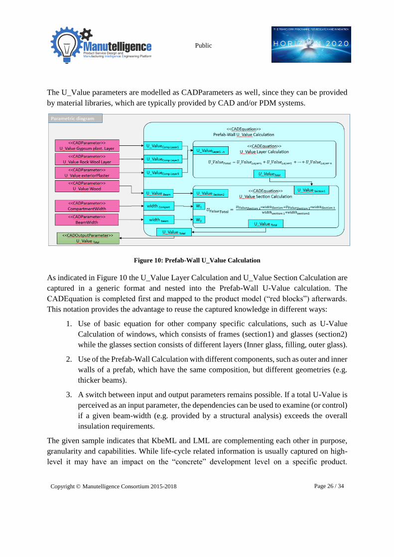
The equations related to Layers of the compartment (each layer with a specific U-Value) can
be nested into one resulting equation, which is covering in addition the distinction between
compartments and beams as illustrated below (Figure 10). The CAD related parameters width
of the beams and width of the compartment can be linked to this resulting U-value equation.
Public
Copyright Manutelligence Consortium 2015-2018 Page 26 / 34
The U_Value parameters are modelled as CADParameters as well, since they can be provided
by material libraries, which are typically provided by CAD and/or PDM systems.
Figure 10: Prefab-Wall U_Value Calculation
As indicated in Figure 10 the U_Value Layer Calculation and U_Value Section Calculation are
captured in a generic format and nested into the Prefab-Wall U-Value calculation. The
CADEquation is completed first and mapped to the product model (“red blocks”) afterwards.
This notation provides the advantage to reuse the captured knowledge in different ways:
1. Use of basic equation for other company specific calculations, such as U-Value
Calculation of windows, which consists of frames (section1) and glasses (section2)
while the glasses section consists of different layers (Inner glass, filling, outer glass).
2. Use of the Prefab-Wall Calculation with different components, such as outer and inner
walls of a prefab, which have the same composition, but different geometries (e.g.
thicker beams).
3. A switch between input and output parameters remains possible. If a total U-Value is
perceived as an input parameter, the dependencies can be used to examine (or control)
if a given beam-width (e.g. provided by a structural analysis) exceeds the overall
insulation requirements.
The given sample indicates that KbeML and LML are complementing each other in purpose,
granularity and capabilities. While life-cycle related information is usually captured on high-
level it may have an impact on the “concrete” development level on a specific product.
Public
Copyright Manutelligence Consortium 2015-2018 Page 27 / 34
Accordingly, methods and tools for knowledge capturing should be aligned and as indicated
above this is indeed feasible, if methods and tools are aligned to each other.
5 Enhancement of the Semantic Facilitator
Domain ontology
One research focus of T3.4 is addressing semantic searches and knowledge retrieval of the
codified engineering knowledge. As outlined in Section 6 one pillar to access formalized
knowledge, once captured by a KbeML, is the XML-basement of the standard itself, which
enables software interpretation. The elements (e.g. a CADComponent or a CADEquation) can
be retrieved by parsing KbeML files and the knowledge (e.g. a parameter value) can be
extracted. Next to this technical access, the T3.4 related research activities focused on the
alignment between the Manutelligence approach and the semantic representation of knowledge.
As described in more detail in D3.1 a semantic representation of the Manutelligence domain
has been set-up in order to enable the integration of the Product Lifecycle and Service Lifecycle
(which are today still separated) for PSS. The major result of this activity is a domain ontology
covering lifecycle related concepts such as Actor, Product, etc. Compared to information
storage in databases, ontologies provide specific advantages, which are relevant for an overall
knowledge retrieval and knowledge management approach (as envisaged in context of
Manutelligence). One significant advantage of ontologies is the ability to perform conclusions
(so-called semantic reasoning), which enable the system to establish causality and thus to detect
inconsistencies or inherent knowledge (Gómez-Pérez et al., 2006). Further, ontologies offer the
advantage that objects can be described fully by attributes and this is independent from
existence or non-existence of instances (e.g. a sensor can have a “provides” relation to
“temperature values” even if it is not providing values yet). Ontologies are characterized by the
fact that they are able to reflect progress (Gómez-Pérez et al., 2006). Different stages of an
object can be directly combined semantically with one single object, which is of high value if
the life-cycle related changes have to be captured (as this is the case for Manutelligence). On
the contrary, databases can only realize this by version numbers, which only represent a
progress by their increasing version numbers. In addition, an adaption of the generally described
methods to a specific problem can be easily realized (e.g. an author knowledge-artefact relation
can be specified to a developer CAD model relation). On the contrary, databases need a tailored
solution to a specific problem and thus are not as comfortable for a generic approach to enable
retrieval of codified engineering knowledge as ontologies. Accordingly, T3.4 has copied the
approach of T3.1 and suggests an ontology to support semantic searches and knowledge
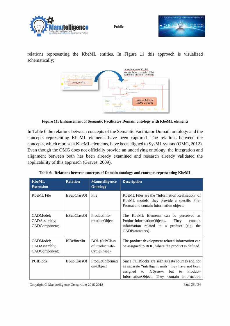
retrieval. The ontology, as proposed by D3.1, has been analysed and enhanced by concepts and
Public
Copyright Manutelligence Consortium 2015-2018 Page 28 / 34
relations representing the KbeML entities. In Figure 11 this approach is visualized
schematically:
Figure 11: Enhancement of Semantic Facilitator Domain ontology with KbeML elements
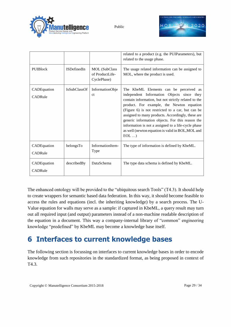
In Table 6 the relations between concepts of the Semantic Facilitator Domain ontology and the
concepts representing KbeML elements have been captured. The relations between the
concepts, which represent KbeML elements, have been aligned to SysML syntax (OMG, 2012).
Even though the OMG does not officially provide an underlying ontology, the integration and
alignment between both has been already examined and research already validated the
applicability of this approach (Graves, 2009).
Table 6: Relations between concepts of Domain ontology and concepts representing KbeML
KbeML
Extension
Relation Manutelligence
Ontology
Description
KbeML File IsSubClassOf File KbeML Files are the “Information Realisation” of
KbeML models, they provide a specific File-
Format and contain Information objects
CADModel;
CADAssembly;
CADComponent;
IsSubClassOf ProductInfo-
rmationObject
The KbeML Elements can be perceived as
ProductInformationObjects. They contain
information related to a product (e.g. the
CADParameters).
CADModel;
CADAssembly;
CADComponent;
ISDefinedIn BOL (SubClass
of ProductLife-
CyclePhase)
The product development related information can
be assigned to BOL, where the product is defined.
PUIBlock IsSubClassOf ProductInformati
on-Object Since PUIBlocks are seen as sata sources and not
as separate “intelligent units” they have not been
assigned to ITSystem but to Product-
InformationObject. They contain information
Public
Copyright Manutelligence Consortium 2015-2018 Page 29 / 34
related to a product (e.g. the PUIParameters), but
related to the usage phase.
PUIBlock ISDefinedIn MOL (SubClass
of ProductLife-
CyclePhase)
The usage related information can be assigned to
MOL, where the product is used.
CADEquation
CADRule
IsSubClassOf InformationObje
ct
The KbeML Elements can be perceived as
independent Information Objects since they
contain information, but not strictly related to the
product. For example, the Newton equation
(Figure 6) is not restricted to a car, but can be
assigned to many products. Accordingly, these are
generic information objects. For this reason the
information is not a assigned to a life-cycle phase
as well (newton equation is valid in BOL,MOL and
EOL …)
CADEquation
CADRule
belongsTo
InformationItem-
Type
The type of information is defined by KbeML.
CADEquation
CADRule
describedBy
DataSchema The type data schema is defined by KbeML.
The enhanced ontology will be provided to the “ubiquitous search Tools” (T4.3). It should help
to create wrappers for semantic based data federation. In this way, it should become feasible to
access the rules and equations (incl. the inheriting knowledge) by a search process. The U-
Value equation for walls may serve as a sample: if captured in KbeML, a query result may turn
out all required input (and output) parameters instead of a non-machine readable description of
the equation in a document. This way a company-internal library of “common” engineering
knowledge “predefined” by KbeML may become a knowledge base itself.
6 Interfaces to current knowledge bases
The following section is focussing on interfaces to current knowledge bases in order to encode
knowledge from such repositories in the standardized format, as being proposed in context of
T4.3.

Public
Copyright Manutelligence Consortium 2015-2018 Page 30 / 34
By default, KbeML models can be used to exchange codified engineering knowledge due to the
openness of SysML (and the SysML extension), which is guaranteed by the XMI standard. As
shown in Table 7, each expression within the XMI-file is dedicated to a unique ID; this way
expressions can be re-used within the file or mapped with other expression. For example, the
equation for the U-Value Section Calculation is dedicated to a specific ID and this way also
mapped to the KBE-Profile CADEquationTerm. The parameter U-ValueTotal is marked as a
CADOutputParameter analogue to this mapping.
Table 7: XMI-file of a KbeML model with highlighted element identifiers
KbeML File (extract) Meaning
...
<ownedAttribute xmi:type="sysML:ConstraintProperty"
xmi:id="_tjOqIw2tEeSOiLl9u1smzQ" name="U_Value SECTION
Calculation" type="_vmWkIAwbEeSuFZ_bSRZnLA">
<defaultValue xmi:type="uml:LiteralString"
xmi:id="_tjOqJA2tEeSOiLl9u1smzQ"
value="(U_Value)_Total = ((U-Value)_Section1 *
width_section1 + (U-Value)_Section2 *
width_section2")/( width_section1 +
width_section2)/>
</ownedAttribute>
...
<ownedAttribute xmi:type="uml:Property"
xmi:id="_tjOqJQ2tEeSOiLl9u1smzQ" name="(U_Value)_Total "
type="_vmWkIAwbEeSuFZ_bSRZnLA">
<defaultValue xmi:type="uml:LiteralString"
xmi:id="_tjOqJg2tEeSOiLl9u1smzQ" value=""/>
...
<KBEProfile:CADEquationTerm
xmi:id="_SfFR4A2uEeSOiLl9u1smzQ"
base_ConstraintProperty="_tjOqIw2tEeSOiLl9u1smzQ"/>
...
<KBEProfile:CADOutputParameter
xmi:id="_Mqv7wA2uEeSOiLl9u1smzQ"
base_Property="_tjOqJQ2tEeSOiLl9u1smzQ"/>
...
U-Value Section Calculation
is defined as a
CADEquationTerm with the
equation as being provided
by Figure 10.
U-ValueTotal is defined as a
CADOutputparameter
with its Value “”
Type CADEquationTerm is
identified by the
corresponding internal ID
Type CADOutputParameter
is identified by the
corresponding internal ID

Public
Copyright Manutelligence Consortium 2015-2018 Page 31 / 34
If parsed, this information can be used to create interfaces to knowledge bases to capture this
knowledge in the standardized format. The XMI elements can be mapped to other applications
such as e.g. parameters, which are defined in the 3DS platform or in CAD. For example, the
CADParameter BeamWidth (of the XMI) can be related to a parameter of a CATIA CADPart
file with its (cumbersome) internal name “Hauptkörper/Block.2/ Skizze.2/Länge.12”. This way
the information can be exchanged between KbeML models and models in CAx-applications
and internally applied. In principle formalized knowledge of the XMI can be used in KBE
related CAD applications directly, since equations can be transferred either. The only limitation
comes along with the CADEquationtherm, which has to be restricted to use the syntax of the
corresponding CAD Application, such as the CATIA KnowledgeAdvisor and its syntax (ref to
Section 2.1).
In Figure 12 the knowledge exchange between a CAD application and a modelling environment
(where a K-Model is managed) is presented schematically. The proposed exchange process
relies on the openness of KbeML, which is guaranteed by the XMI standard.
Figure 12: Parameter mapping between KbeML model and commercial CAx application (schematic)
Of-course a mapping may also be used for a knowledge transfer into KbeML: user information
sources can be defined as KbeML elements and values can be imported into a corresponding
model and reused afterwards in the models (section 3.1).
Even specific Elements such as the predefined StatisticalElements can be mapped to
applications (such as Rapidminer (Rapidminer, 2016)) enabling to create semi-automated
workflows directly from the KbeML models.

Public
Copyright Manutelligence Consortium 2015-2018 Page 32 / 34
7 Summary and conclusions
As outlined in section 3 the deliverable summarizes the T3.4 related activities. In reference to
an analysis of the 3DS platform and its main component (namely CATIA), current
shortcomings of commercial KBE applications have been identified with a special focus on
Life-Cycle and usage information (such as sensor data or user feedback), which have to be
provided for design. The modelling language KbeML, which has been specified by BIBA and
enhanced and refined in context of the Manutelligence research, approaches to become a
standardized representation for codified engineering knowledge. It inherits the capability to
represent product usage information and data in terms of sensors & sources belonging to a
product-class (e.g. Ferrari FF) as well as related to usage data belonging to the instances (e.g.
my Ferrari FF, your Ferrari FF). Specific elements, called StatisticalElements, enabling to
document the statistical analysis methods, are used to transfer usage data as input for the
product-development phase (e.g. median of the engine temperatures of your Ferrari, & my
Ferrari).
As outlined exemplarily for the insulation of prefab walls KbeML is complementing the life-
cycle modelling language LML and allows to detail the identified actions, such as insulation
calculation. It enables to codify required rules and equations needed to represent aspects of
interest, such as heat-loss or vice versa required thicknesses of wall layers. Since it is based
upon a formal machine-readable representation of knowledge, KbeML enables to make
development-related rules & algorithms accessible for different CAx Systems. In principle,
such codified information can be used on different levels. Equations or parameters can be
exchanged among systems and/or the models can be used as blue prints for automated design
solutions of both types (the object oriented programming approach or geometry based
approach).
Finally, the research activities focussed on the alignment of KbeML to the facilitator domain
ontology, to enable retrieval of codified engineering knowledge from the “P-S engineering and
manufacturing ubiquitous search tools”. The enhancement of the ontology with additional
elements related to KbeML will support semantic search as envisaged in Manutelligence as
well.
All T3.4 related results will be provided to parallel and subsequent Manutelligence activities,
particularly to T4.3 for the development of “ubiquitous search Tools”, to T3.1 for the semantic
facilitator ontology and to WP6 for setting up the smart house demonstrator.

Public
Copyright Manutelligence Consortium 2015-2018 Page 33 / 34
8 References
Colombo, G., Pugliese, D., Klein, P., Lutzenberger, J., 2014. A study for neutral format to
exchange and reuse engineering knowledge in KBE applications, in: Engineering,
Technology and Innovation (ICE), 2014 International ICE Conference on. IEEE, pp. 1–
10.
Curran, R., Verhagen, W.J.C., van Tooren, M.J.L., van der Laan, T.H., 2010. A
multidisciplinary implementation methodology for knowledge based engineering:
KNOMAD. Expert Syst. Appl., Advances in Aligning Knowledge Systems, Improving
Business Logistics, Driving Innovation and Adapting Customer Centric Services 37,
7336–7350. doi:10.1016/j.eswa.2010.04.027
Dassault, 2016. 3D CAD CATIA Solutions by Dassault Systèmes [WWW Document]. URL
http://www.3ds.com/products-services/catia/ (accessed 12.19.16).
Dassault, 3DS, 2016. Products & Services [WWW Document]. URL http://www.3ds.com/en-
uk/products-services/ (accessed 12.19.16).
Franke, M., Klein, P., Schröder, L., Thoben, K.-D., 2011. Ontological Semantics of Standards
and PLM Repositories in the Product Development Phase, in: Bernard, A. (Ed.), Global
Product Development. Springer Berlin Heidelberg, pp. 473–482. doi:10.1007/978-3-
642-15973-2_48
Gómez-Pérez, A., Fernandez-Lopez, M., Corcho, O., 2006. Ontological Engineering: with
examples from the areas of Knowledge Management, e-Commerce and the Semantic
Web. First Edition. Springer Science & Business Media.
Graves, H., 2009. Integrating SysML and OWL, in: Proceedings of the 6th International
Conference on OWL: Experiences and Directions-Volume 529. CEUR-WS. org, pp.
117–124.
Kulon, J., Broomhead, P., Mynors, D.J., 2006. Applying knowledge-based engineering to
traditional manufacturing design. Int. J. Adv. Manuf. Technol. 30, 945–951.
doi:10.1007/s00170-005-0067-0
La Rocca, G., Van Tooren, M.J.L., 2007. Enabling distributed multi-disciplinary design of
complex products: a knowledge based engineering approach. J. Des. Res. 5, 333–352.
LML, 2015. Specification | Lifecycle Modeling Language [WWW Document]. URL
http://www.lifecyclemodeling.org/specification/ (accessed 12.21.16).
Milton, N.R., 2008. Knowledge technologies. Polimetrica.
OMG, 2016. Object Management Group [WWW Document]. URL http://www.omg.org/
(accessed 12.22.16).

Public
Copyright Manutelligence Consortium 2015-2018 Page 34 / 34
OMG, 2012. SysML 1.3 [WWW Document]. URL http://www.omg.org/spec/SysML/
(accessed 3.18.16).
Prasad, B., 2005. What distinguishes KBE from automation. COE NewsNet.
Rapidminer, 2016. Data Science | Machine Learning [WWW Document]. RapidMiner. URL
https://rapidminer.com/ (accessed 1.10.17).
Siemens NX, 2016. NX: Siemens PLM Software [WWW Document]. URL
https://www.plm.automation.siemens.com/de_de/products/nx/ (accessed 12.22.16).
Skarka, W., 2007. Application of MOKA methodology in generative model creation using
CATIA. Eng. Appl. Artif. Intell. 20, 677–690. doi:10.1016/j.engappai.2006.11.019
Stokes, M., 2001. Managing engineering knowledge: MOKA: methodology for knowledge
based engineering applications. Professional Engineering Publishing London.
Verhagen, W.J., Bermell-Garcia, P., van Dijk, R.E., Curran, R., 2012. A critical review of
Knowledge-Based Engineering: An identification of research challenges. Adv. Eng.
Inform. 26, 5–15.
Vermeulen, B., 2007. Knowledge based method for solving complexity in design problems.
Wellsandt, S., Wuest, T., Hribernik, K., Thoben, K.-D., 2015. Information Quality in PLM: A
Product Design Perspective, in: Advances in Production Management Systems:
Innovative Production Management Towards Sustainable Growth. Springer, pp. 515–
523.
Wonnacott, T.H., Wonnacott, R.J., 1972. Introductory statistics. Wiley New York.