data fusion processing for the multi-spectral sensor ... · the multi-spectral sensor surveillance...
TRANSCRIPT

Approved for public release; distribution is unlimited.
Data Fusion Processing for theMulti-Spectral Sensor Surveillance System (M4S)
Dr. William BarkerDr. Shozo Mori
Elizabeth G. SullingerMichael Boe
Raytheon Systems CompanyAdvanced C3I Systems1290 Parkmoor Avenue
San Jose, CA 95126(408) 293-4400
ABSTRACT
The Multi-Spectral Sensor Surveillance System (M4S) is a multi-year ONR-sponsored program totransition mature sensor and data fusion technology into existing and/or near-future airborne surveillanceplatforms. A study phase and on-board sensor data fusion concept-of-proof demonstration have beencompleted in 1997. This paper describes the data fusion concepts, architecture, and algorithms that havebeen designed and demonstrated in these efforts.
The data fusion architecture selected for M4S is a distributed design in which each on-board sensor sub-system is equipped with a single-sensor tracking unit satisfying all the sensor-specific tracking needs inaddition to required sensor data processing capability. Thus scan-to-scan, or frame-to-frame correlation isbasically resolved on a single-sensor basis, and the outputs of each sensor-subsystem are typically single-sensor tracks, or tracklets, i.e., stochastically independent fractions of tracks. Those outputs are then fedinto a centralized multi-sensor, data fusion process that performs track-to-track association analysis andfuses appropriate single-sensor tracks into multiple-sensor tracks.
In this way, each sensor sub-system provides target information complementary to each other as well asreinforcing each other, in terms of both target identification and target localization, so that the central datafusion process may produce a best picture of each target of interest. This system architecture also allowseach sensor-specific tracker to temporarily lose hold of some targets but to re-acquire them later, yet tomaintain continuous target recognition.
This data fusion process is also connected, through an external communication network, to off-boardintelligence and surveillance sources, such as Rivet Joint, AWACS, U2, JSTARS, etc., to provide thesystem with a complete tactical picture. This distributed architecture requires each on-board sensor sub-
REPORT DOCUMENTATION PAGE Form Approved OMB No.0704-0188
Public reporting burder for this collection of information is estibated to average 1 hour per response, including the time for reviewing instructions, searching existing data sources, gathering and maintaining the data needed, and completingand reviewing this collection of information. Send comments regarding this burden estimate or any other aspect of this collection of information, including suggestions for reducing this burder to Department of Defense, WashingtonHeadquarters Services, Directorate for Information Operations and Reports (0704-0188), 1215 Jefferson Davis Highway, Suite 1204, Arlington, VA 22202-4302. Respondents should be aware that notwithstanding any other provision oflaw, no person shall be subject to any penalty for failing to comply with a collection of information if it does not display a currently valid OMB control number. PLEASE DO NOT RETURN YOUR FORM TO THE ABOVE ADDRESS.
1. REPORT DATE (DD-MM-YYYY)01-01-1998
2. REPORT TYPEConference Proceedings
3. DATES COVERED (FROM - TO)xx-xx-1998 to xx-xx-1998
4. TITLE AND SUBTITLEData Fusion Processing for the Multi-Spectral Sensor Surveillance System (M4S)Unclassified
5a. CONTRACT NUMBER5b. GRANT NUMBER5c. PROGRAM ELEMENT NUMBER
6. AUTHOR(S)Barker, William ;Mori, Shozo ;Sullinger, Elizabeth G. ;Boe, Michael ;
5d. PROJECT NUMBER5e. TASK NUMBER5f. WORK UNIT NUMBER
7. PERFORMING ORGANIZATION NAME AND ADDRESSRaytheon Systems CompanyAdvanced C3I Systems1290 Parkmoor Ave.San Jose, CA95126
8. PERFORMING ORGANIZATION REPORTNUMBER
9. SPONSORING/MONITORING AGENCY NAME AND ADDRESSDirector, CECOM RDECNight Vision and Electronic Sensors Directorate, Security Team10221 Burbeck RoadFt. Belvoir, VA22060-5806
10. SPONSOR/MONITOR'S ACRONYM(S)11. SPONSOR/MONITOR'S REPORTNUMBER(S)
12. DISTRIBUTION/AVAILABILITY STATEMENTAPUBLIC RELEASE,13. SUPPLEMENTARY NOTESSee Also ADM201041, 1998 IRIS Proceedings on CD-ROM.14. ABSTRACTThe Multi-Spectral Sensor Surveillance System (M4S) is a multi-year ONR-sponsored program to transition mature sensor and data fusiontechnology into existing and/or near-future airborne surveillance platforms. A study phase and on-board sensor data fusion concept-of-proofdemonstration have been completed in 1997. This paper describes the data fusion concepts, architecture, and algorithms that have beendesigned and demonstrated in these efforts. The data fusion architecture selected for M4S is a distributed design in which each on-board sensorsubsystem is equipped with a single-sensor tracking unit satisfying all the sensor-specific tracking needs in addition to required sensor dataprocessing capability. Thus scan-to-scan, or frame-to-frame correlation is basically resolved on a single-sensor basis, and the outputs of eachsensor-subsystem are typically singlesensor tracks, or tracklets, i.e., stochastically independent fractions of tracks. Those outputs are then fedinto a centralized multi-sensor, data fusion process that performs track-to-track association analysis and fuses appropriate single-sensor tracksinto multiple-sensor tracks. In this way, each sensor sub-system provides target information complementary to each other as well as reinforcingeach other, in terms of both target identification and target localization, so that the central data fusion process may produce a best picture ofeach target of interest. This system architecture also allows each sensor-specific tracker to temporarily lose hold of some targets but tore-acquire them later, yet to maintain continuous target recognition. This data fusion process is also connected, through an externalcommunication network, to off-board intelligence and surveillance sources, such as Rivet Joint, AWACS, U2, JSTARS, etc., to provide thesystem with a complete tactical picture. This distributed architecture requires each on-board sensor sub-system to perform more or lessautonomously. In order to assist single-sensor track initiation processes, however, the central data fusion process provides feedback tracks tothe sensor sub-systems, as well as cross-sensor or off-board cueing instructions. Originally, four non-developmental sensors, ESM, radar,EO/IR, and laser sensors, have been chosen for on-board sensors that provide a unique combination of electromagnetic and optical, and passiveand active, sensing. The distributed system architecture, however, allows us to expand or modify this sensor suite without any significantmodification to the system design, in a more or less plug-n-play fashion. The proof-of-concept demonstration was successfully completed in1997 showing the full potential of the system concept, using emulated on-board sensors and off-board sources. In the succeeding years inPhase II, development of concepts of on-board, on-line, sensor and platform resource management will take place, as well as switchingemulated sensors to real sensors, possibly on an airborne platform.15. SUBJECT TERMS16. SECURITY CLASSIFICATION OF: 17. LIMITATION
OF ABSTRACTPublic Release
18.NUMBEROF PAGES18
19. NAME OF RESPONSIBLE PERSONFenster, [email protected]
a. REPORTUnclassified
b. ABSTRACTUnclassified
c. THIS PAGEUnclassified
19b. TELEPHONE NUMBERInternational Area CodeArea Code Telephone Number703767-9007DSN427-9007
Standard Form 298 (Rev. 8-98)Prescribed by ANSI Std Z39.18

system to perform more or less autonomously. In order to assist single-sensor track initiation processes,however, the central data fusion process provides feedback tracks to the sensor sub-systems, as well ascross-sensor or off-board cueing instructions.
Originally, four non-developmental sensors, ESM, radar, EO/IR, and laser sensors, have been chosen foron-board sensors that provide a unique combination of electromagnetic and optical, and passive andactive, sensing. The distributed system architecture, however, allows us to expand or modify this sensorsuite without any significant modification to the system design, in a more or less plug-n-play fashion.
The proof-of-concept demonstration was successfully completed in 1997 showing the full potential of thesystem concept, using emulated on-board sensors and off-board sources. In the succeeding years in PhaseII, development of concepts of on-board, on-line, sensor and platform resource management will takeplace, as well as switching emulated sensors to real sensors, possibly on an airborne platform.
1.0 INTRODUCTION
A new world order is changing tactical threat perspectives and operations. New pressures to minimizeforce exposure and attrition while improving asset effectiveness in limited conflict engagements are keyrequirements behind this tactical philosophy. Because of likely limited warfare in confined battle areas,situation awareness, combat identification friend or foe, secure C3 on the move, and re-locatable targetlocation systems will be required to support these needs. The Navy has a pervasive and expanded role inthis new tactical scenario. Littoral Warfare and force projection ashore, in concert with other forcestructures, is vital to new tactical scenarios. Shipboard Surveillance will be the key operational factor inJoint Mission Littoral Warfare.
A powerful approach to Littoral surveillance is the deployment of Unmanned Air Vehicles (UAVs) orother airborne platforms equipped with multi-spectral surveillance capability. An aircraft, launched fromland or a Carrier Battle Group, provides critical, real-time intelligence information necessary for targetsurveillance, location, identification, battle planning and post-strike Battle Damage Assessment (BDA).Figure 1.1 depicts the concept of operations for a Multi-Spectral Sensor Surveillance System (M4S). Inthis scenario a single air vehicle outfitted with multi-spectral sensors is able to detect critical targetsthrough fusion of contact reports received from off-board sensors and its own GMTI Radar. Armed withthis information the vehicle and its sensors are tasked to further classify and identify these targets utilizingits short-range sensors. Fusing the information from both the long and short-range sensors allows theM4S to continue to maintain track on these critical targets even at long range.

L o n g R a n g e S e n s o rG M T I f o r D e t e c t i o n
M a i n t a i n T r a c ka t L o n g R a n g eS h o r t R a n g e S e n s o r
f o r C l a s s i f i c a t i o n
S A - 8
S A - 8
T 6 0T 6 0
T 6 0T 6 0
S w a y i n g T r e e( G M T I R e t u r n )
D a t aF u s i o n
R e s o u r c eM a n a g e r
W a y p o i n t s
M 4 S
R o c k( F L I R H o t S p o t )
P lu g & Pl ay
S en so rs
S A - 8
M i n i m i z e t i m e t ol o c a t e a n d I D t a r g e t ( s )
M a x i m i z e c o v e r a g e( A r e a u n d e r t r a c k )
9 7 - 1 2 9 - 0 0 1
Figure 1.1M4S Concept of Operations
To demonstrate this capability, ONR has sponsored a multi-year program to transition notional sensorsand data fusion technology into existing or near-future airborne surveillance platforms. The objective ofthis program is to prove the ability of enhanced data fusion algorithms to detect, identify, and track targetswith improved detection probability and greater position and identification accuracy in a reduced amountof time with fewer false alarms using multiple dissimilar on-board sensors and off-board information.
The team of ONR, Litton Applied Technology, Raytheon Systems Company, QuesTech, CSCI, andSPAWAR Systems Center has completed a study phase and on and off-board sensor data fusion concept-of-proof demonstration. The primary technical objective of this team is to develop a design architectureand enhanced data fusion algorithms that support the goal of critical target identification in a reducedtime-line.
The data fusion architecture selected for M4S is a distributed design in which each on-board sensor sub-system is equipped with a single-sensor tracking unit satisfying all the sensor-specific tracking needs inaddition to required sensor data processing capability. Thus scan-to-scan, or frame-to-frame correlation isbasically resolved on a single-sensor basis. These outputs are then fed into a centralized multi-sensor,data fusion process that performs track-to-track association analysis and fuses appropriate single-sensortracks into multiple-sensor tracks. In this way, each sensor sub-system provides target information that isboth complementary and reinforcing to the others so that the central data fusion process may produce abest picture of each target of interest. This system architecture also allows each sensor-specific tracker totemporarily lose hold of some targets yet the overall system can maintain continuous target recognition.

This data fusion process is also connected, through an external communication network, to off-boardintelligence and surveillance sources, such as Rivet Joint, AWACS, U2, JSTARS, etc., to provide thesystem with a complete tactical picture. This distributed architecture requires each on-board sensor sub-system to perform more or less autonomously. In order to assist single-sensor track initiation processes,however, the central data fusion process provides feedback tracks to the sensor sub-systems, as well ascross-sensor or off-board cueing instructions.
Four notional sensors, ESM, radar, EO/IR, and laser sensors have been chosen for on-board sensors thatprovide a unique combination of electromagnetic and optical, and passive and active, sensing. Thedistributed system architecture, however, allows us to expand or modify this sensor suite without anysignificant modification to the system design, in a more or less plug-n-play fashion.
The M4S proof-of-concept demonstration was successfully completed in 1997 showing the full potentialof the system concept, using emulated on-board sensors and off-board sources. In the coming years,development of concepts for on-board, on-line, sensor and platform resource management will take place,as well as switching emulated sensors to real sensors, with the goal of demonstrating M4S on an airborneplatform.
2.0 DISTRIBUTED DATA FUSION ARCHITECTURE FOR M4S
The choice between a distributed or centralized architecture is one of the most important design decisionsto be made in the development of any dissimilar source data fusion system. A distributed fusionarchitecture is characterized by a number of parallel processing channels each of which deals with asubset of the fusion problem. These processing channels are then combined to generate an integratedtrack database. A centralized fusion architecture is essentially the opposite - the entire fusion problem isdealt with as a single entity. Each of these alternatives offers specific advantages and disadvantages, andthe selection requires a careful consideration of the intended application and the nature of the input sensorreports.
As described in the previous section, the objective of M4S is to prove the ability of enhanced data fusionalgorithms to detect, identify, and track targets with improved detection probability and greater positionand identification accuracy in a reduced amount of time using multiple dissimilar on-board. For M4S wedid not limit ourselves to the exact capabilities of existing sensors, but considered the probable evolutionof sensor capabilities to the year 2005. The specific sensors types considered include a multi-mode radar,a infrared sensor, an ELINT system, and a continuous wave laser capable of detecting vehicle vibrations.Additionally, we assumed the availability of off-board sensor data provide by over communication linksto the M4S platform.
The notional radar is similar to a potential variant of the Raytheon AN/APS-137B (V) 5 and is capable ofoperating in the following modes:
GMTI (Ground Moving Target Indicator) for the detection of moving ground targets,PPI (Plan Position Indicator mode) for the detection of ships and coast lines,SAR (Synthetic Aperture Radar) for imaging and classifying fixed objects, andInverse- Synthetic Aperture Radar (ISAR) for imaging moving objects such as ships.
The notional IR sensor has capabilities similar to the Raytheon FLIR developed for the LAMPShelicopter. It is capable of operating in both a wide field of view for search and detection, and narrowfield of view for target classification.
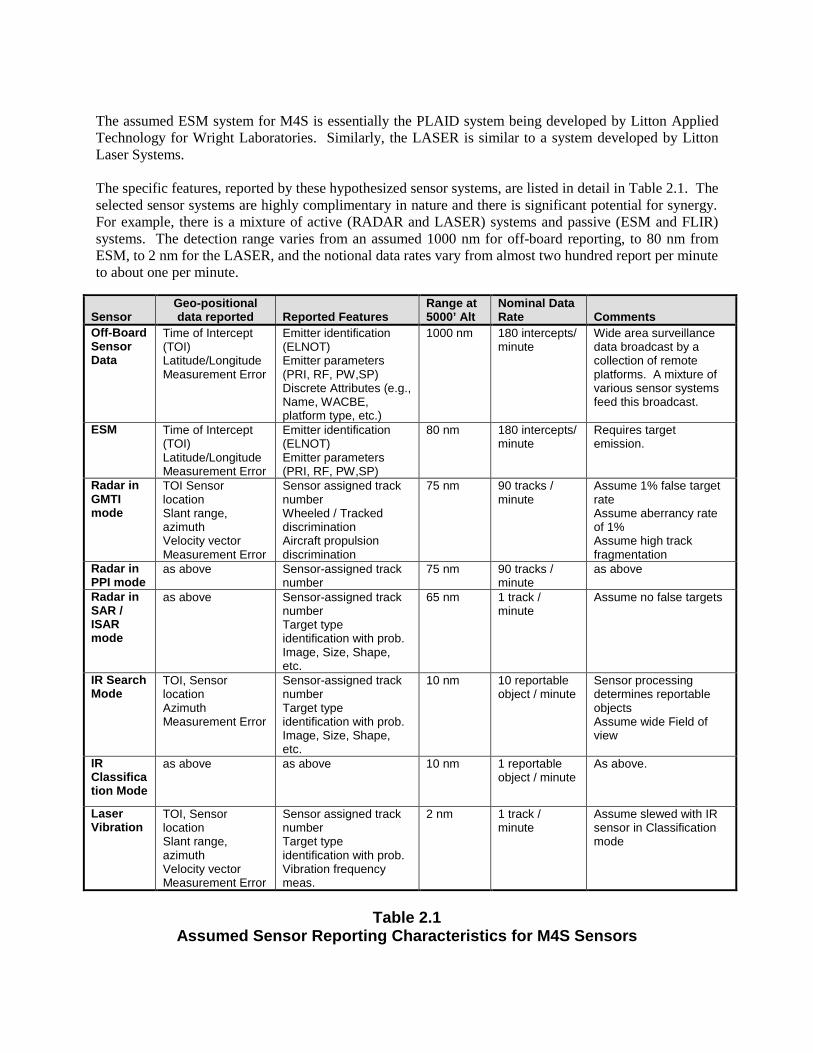
The assumed ESM system for M4S is essentially the PLAID system being developed by Litton AppliedTechnology for Wright Laboratories. Similarly, the LASER is similar to a system developed by LittonLaser Systems.
The specific features, reported by these hypothesized sensor systems, are listed in detail in Table 2.1. Theselected sensor systems are highly complimentary in nature and there is significant potential for synergy.For example, there is a mixture of active (RADAR and LASER) systems and passive (ESM and FLIR)systems. The detection range varies from an assumed 1000 nm for off-board reporting, to 80 nm fromESM, to 2 nm for the LASER, and the notional data rates vary from almost two hundred report per minuteto about one per minute.
SensorGeo-positionaldata reported Reported Features
Range at5000’ Alt
Nominal DataRate Comments
Off-BoardSensorData
Time of Intercept(TOI)Latitude/LongitudeMeasurement Error
Emitter identification(ELNOT)Emitter parameters(PRI, RF, PW,SP)Discrete Attributes (e.g.,Name, WACBE,platform type, etc.)
1000 nm 180 intercepts/minute
Wide area surveillancedata broadcast by acollection of remoteplatforms. A mixture ofvarious sensor systemsfeed this broadcast.
ESM Time of Intercept(TOI)Latitude/LongitudeMeasurement Error
Emitter identification(ELNOT)Emitter parameters(PRI, RF, PW,SP)
80 nm 180 intercepts/minute
Requires targetemission.
Radar inGMTImode
TOI SensorlocationSlant range,azimuthVelocity vectorMeasurement Error
Sensor assigned tracknumberWheeled / TrackeddiscriminationAircraft propulsiondiscrimination
75 nm 90 tracks /minute
Assume 1% false targetrateAssume aberrancy rateof 1%Assume high trackfragmentation
Radar inPPI mode
as above Sensor-assigned tracknumber
75 nm 90 tracks /minute
as above
Radar inSAR /ISARmode
as above Sensor-assigned tracknumberTarget typeidentification with prob.Image, Size, Shape,etc.
65 nm 1 track /minute
Assume no false targets
IR SearchMode
TOI, SensorlocationAzimuthMeasurement Error
Sensor-assigned tracknumberTarget typeidentification with prob.Image, Size, Shape,etc.
10 nm 10 reportableobject / minute
Sensor processingdetermines reportableobjectsAssume wide Field ofview
IRClassification Mode
as above as above 10 nm 1 reportableobject / minute
As above.
LaserVibration
TOI, SensorlocationSlant range,azimuthVelocity vectorMeasurement Error
Sensor assigned tracknumberTarget typeidentification with prob.Vibration frequencymeas.
2 nm 1 track /minute
Assume slewed with IRsensor in Classificationmode
Table 2.1Assumed Sensor Reporting Characteristics for M4S Sensors
Additionally, the reported features are highly dependent on the specific sensor and mode, and includeonly the presence of a target (RADAR in PPI mode), images (SAR, IRAR, and FLIR), ESM parametrics,and acoustic vibration signature data.
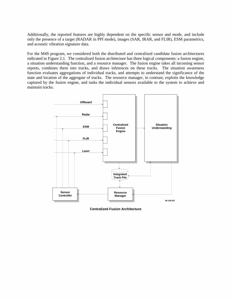
For the M4S program, we considered both the distributed and centralized candidate fusion architecturesindicated in Figure 2.1. The centralized fusion architecture has three logical components: a fusion engine,a situation understanding function, and a resource manager. The fusion engine takes all incoming sensorreports, combines them into tracks, and draws inferences on these tracks. The situation awarenessfunction evaluates aggregations of individual tracks, and attempts to understand the significance of thestate and location of the aggregate of tracks. The resource manager, in contrast, exploits the knowledgecaptured by the fusion engine, and tasks the individual sensors available to the system to achieve andmaintain tracks.
98-108-003
SituationUnderstanding
IntegratedTrack File
CentralizedFusionEngine
ResourceManager
SensorController
Offboard
Radar
ESM
FLIR
Laser
Centralized Fusion Architecture

Offboard
Radar
Laser
Sen
sor S
peci
fic In
terf
ace
SensorTarget
Tracker
SensorTarget
Tracker
SensorTarget
Tracker
SensorController
LaserTrack File
RadarTrack File
OffboardTrack File
SensorTrack
Fusion
SituationUnderstanding
IntegratedTrack File
ResourceManager
Tracklets
98-108-002
Distributed Fusion Architecture
Figure 2.1Centralized and Distributed Fusion Architectures considered for M4S
In the distributed alternative, the fusion engine is split into a series of single sensor target trackers, and themulti-sensor track fuser. Thus, four sequential processing steps perform differing levels of fusion: thesensor target tracker, the track fuser, situation understanding, and resource management. These functionsroughly correspond to the definition for Levels 1 through 4 data fusion as defined by the Joint Director'sof Laboratories Data Fusion sub panel.
The sensor target trackers correlate information provided by a single sensor or a collection of similarsensors. To do this, the sensor target tracker exploits specific features generated by a sensor, includingposition, to construct pure output target tracks. For example, for the ESM sensor target tracker, theinformation specific features include those listed in Table 2-1: RF, PRI, SP, and PW. Since each sensortarget tracker can exploit similar features to aid in it correlation decision, it reliability is significantlyenhanced.
The output of this stage is a “tracklet.” The notion of a tracklet is an essential feature of the distributedarchitecture. Tracklets are small, stochastically independent portions of a track made up of a sequence ofcontact reports from single sensor (or sensor type). Each tracklet has an associated tracker numbertogether with whatever features have been observed by the sensor. Tracklets have temporal extent, andthus, a derived velocity component.
The second stage of the distributed fusion process is the multi-sensor track fuser. The multi-sensor trackfuser receives a sequence of tracklets from sensor target trackers, and correlates these tracklets together,largely because of the track number provided by the sensor target tracker. In this fashion, the fuserreconstructs the tracks maintained by the sensor target tracker.

The challenge of the track fuser, then is to determine when a given target track is represented in the datastream by more than one target tracker. The sensor track fuser exploits the temporal extent of thetracklets to increase the reliability of track correlation. Feasibility tables also support the sensor trackfuser. These tables specify which combinations of sensor features are feasibly on platforms or objects ofinterest.
There is some research to indicate that a centralized fusion architecture is optimal under a number ofcircumstances. See for example references [2] and [3]. For M4S, however, we have selected adistributed fusion architecture. The reasons for this decision are driven by a number of implementationconsiderations. These include:
Computational resources are a significant concern in the M4S environment. It is important that thesystem keep up with the sensor data with no significant data loss. By distributing the processing, theproblem of data loss is effectively managed. The distributed architecture allows us to host the sensortarget trackers on separate processors from the fusion processor. Each of these processors can be sized tomeet the specific processing required of that data path. Moreover, the tracklet approach of inter-processorcommunications allows the fusion processor to query the sensor tracker for data when it is free to acceptmore data. The query – response approach automatically throttle the input rate to the sensor fuser to therate at which it can process the data. In the interim, the sensor target tracker can continue to extend thetemporal extent of tracklets.
The distributed architecture allows plug and play capability. Each sensor target tracker can be designedto exploit the special features generated by each sensor. This capability allows for the implementation ofalgorithms with very effective correlation of similar source data. Moreover, each sensor target trackercan convert the input sensor stream into a standard tracklet format accepted by the sensor fuser. Thequery response approach automatically prevents the sensor fuser from being saturated with data providedby the new feed. Thus, a new source of information can be effectively added to the sensor fuser in a plugand plan fashion.
3.0 SENSOR TRACK SOFTWARE
As mentioned above, each sensor sub-system has its own sensor signal processor and a single-sensortracker, as well as necessary sensor control mechanism. As shown in Figure 3.1, a rather standard ortraditional tracking system architecture was chosen for each single-sensor tracker. This softwareprocesses a frame (or scan) of sensor detections to maintain single-sensor tracks and outputs those tracks,judged to be sufficiently mature, to the multi-sensor data fusion process.

Single-SensorTracks to
Multi-SensorData Fusion Process
Frame-to-Track-DB
Correlation (JVC)
(Multi-Level, Multi-Step)
Track Initiation
Track Update
(Track Maintenance)
TrackMonitor
TrackTermination
Single-SensorTrack Database
Sensor DetectionFrames (Scans)
CorrelatedDetection-Track Pairs
UnassignedMeasurements
Updated Tracks
New Tracks
Mature tracks
CandidateTracks
Feedback Tracks from Multi-Sensor Data-Fusion Process
Figure 3.1Single-Sensor Tracker Software
Each frame of detections (or reports) from the sensor signal processor is input into the frame-to-trackcorrelator to obtain the frame-wise optimal report-to-track correlation (association). For this purpose, theJVC assignment algorithm, known to be the most efficient, is used. The track update process updates theassociated report-to-track pairs and unassociated reports are fed into the track initiation process. Thetrack initiation algorithm is designed to be generally multi-level and multi-step. The track terminationprocess, another standard component, is also used to terminate tracks that are not updated more than aspecified time period. The tracks that are in the track database and that are judged to be “mature” tracksby the track monitor process will be fed into the multi-sensor data-fusion process. In order to alleviate thetrack initiation function, multi-sensor tracks may be fed back to each single-sensor tracker as necessary.
The tracks that are judged to be “mature” enough are output to the multi-sensor, data-fusion process,through a track monitor. When a track has accumulated a large number of reports (or measurements)from each sensor, it is not efficient to move the whole track as a set. An alternative is to represent thetrack by the target state distribution at the most recent update time. By doing so, we reduce the necessaryinternal communication bandwidth significantly, but, at the same time, we may loose crucial informationnecessary to fuse information from multiple sensors. Therefore, a compromise was made by aggregatinginformation contained in an appropriate number of consecutive sensor reports. Those subsets of sensorreports are called tracklets, as a small aggregation of temporally local sets of sensor reports. The lengthof each tracklets can be determined by the track monitor of each sensor sub-system based on the sensorrevisit rate, the target dynamics, and designed internal communication bandwidth. In other words, thesetracklets have been chosen as a primary unit of communication among all the sub-systems within theoverall data fusion systems.
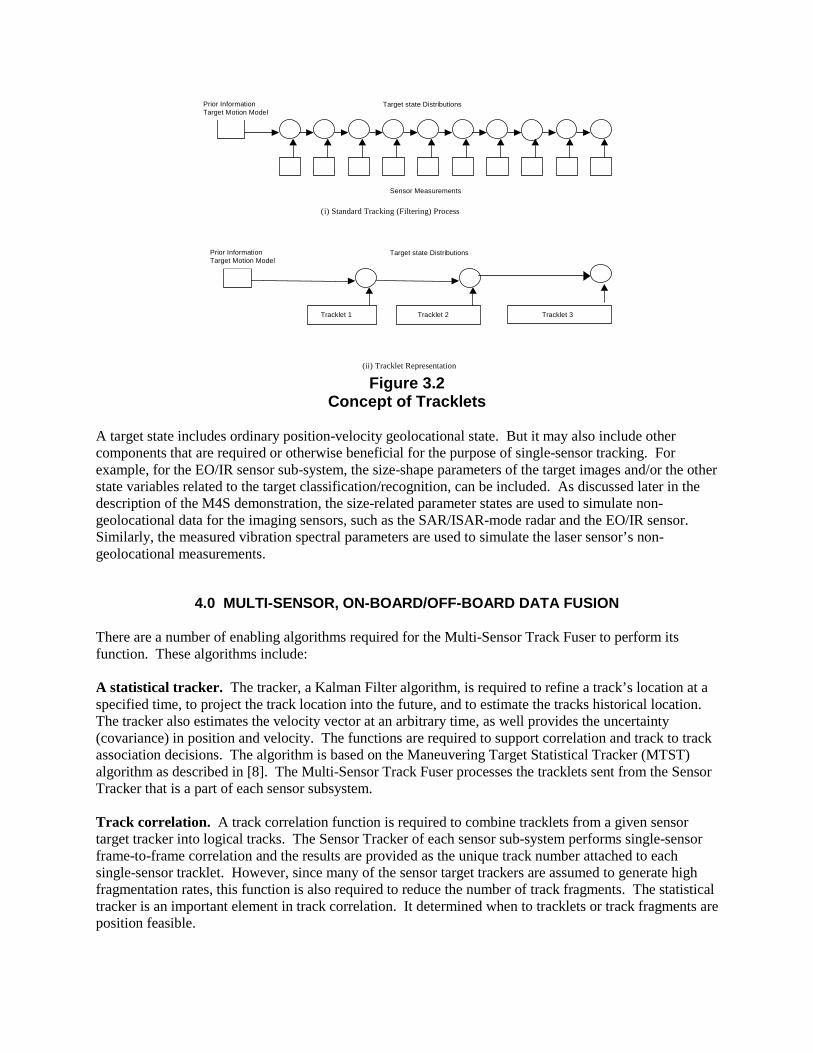
Each tracklet is an aggregation of consecutive sensor reports. There are several approaches to obtain thesufficient statistics for each tracklet. For the M4S data fusion system, the decorrelation approach wasselected. In this approach, tracklet statistics are calculated from the target state distribution at the end ofthe last tracklet and from the end of the current tracklet. This is illustrated in Figure 3.2. As you can seein this figure each sensor report (or detection) is shown by a box, and each target state estimate at a giventime is illustrated as a circle which is an accumulation of information contained in all the reports up tothat point. In order to calculate the statistics of a given tracklet, we subtract the information accumulatedinto the target state distribution (up to the last time a tracklet was produce) from the current target statedistribution. This results in only “new” information being added to this track.
Tracklet 1 Tracklet 2 Tracklet 3
Sensor Measurements
Prior InformationTarget Motion Model
Target state Distributions
(i) Standard Tracking (Filtering) Process
Prior InformationTarget Motion Model
Target state Distributions
(ii) Tracklet Representation
Figure 3.2Concept of Tracklets
A target state includes ordinary position-velocity geolocational state. But it may also include othercomponents that are required or otherwise beneficial for the purpose of single-sensor tracking. Forexample, for the EO/IR sensor sub-system, the size-shape parameters of the target images and/or the otherstate variables related to the target classification/recognition, can be included. As discussed later in thedescription of the M4S demonstration, the size-related parameter states are used to simulate non-geolocational data for the imaging sensors, such as the SAR/ISAR-mode radar and the EO/IR sensor.Similarly, the measured vibration spectral parameters are used to simulate the laser sensor’s non-geolocational measurements.
4.0 MULTI-SENSOR, ON-BOARD/OFF-BOARD DATA FUSION
There are a number of enabling algorithms required for the Multi-Sensor Track Fuser to perform itsfunction. These algorithms include:
A statistical tracker. The tracker, a Kalman Filter algorithm, is required to refine a track’s location at aspecified time, to project the track location into the future, and to estimate the tracks historical location.The tracker also estimates the velocity vector at an arbitrary time, as well provides the uncertainty(covariance) in position and velocity. The functions are required to support correlation and track to trackassociation decisions. The algorithm is based on the Maneuvering Target Statistical Tracker (MTST)algorithm as described in [8]. The Multi-Sensor Track Fuser processes the tracklets sent from the SensorTracker that is a part of each sensor subsystem.
Track correlation. A track correlation function is required to combine tracklets from a given sensortarget tracker into logical tracks. The Sensor Tracker of each sensor sub-system performs single-sensorframe-to-frame correlation and the results are provided as the unique track number attached to eachsingle-sensor tracklet. However, since many of the sensor target trackers are assumed to generate highfragmentation rates, this function is also required to reduce the number of track fragments. The statisticaltracker is an important element in track correlation. It determined when to tracklets or track fragments areposition feasible.

Track-to-Track association. This is the fundamental algorithm in the sensor track fuser. It determineswhen two tracks from different sources represent the same physical object. To accomplish this, the track-to-track association algorithm compares the entire track estimates generated by the statistical tracker. Italso uses feasibility tables employed in threat inferencing to determine which combinations of reportfeatures are feasible. The Sensor Track Fuser Process maintains those multi-sensor fused tracks as a two-level structure as illustrated in Figure 4.1.
ESM TrackEmitter 1
ESM TrackEmitter 2
ESM TrackEmitter 3 Radar Track
Multi-SensorFused (Integrated)
Tracks
EO/IR Track Laser Track
Fragment 1 Fragment 2
Figure 4.1Multi-Sensor Fused (Integrated) Tracks Data Structure
A multi-sensor, fused track consists of the union of all the tracklets contained in its component tracks asshown in Figure 4.1. However, the Sensor Track Fuser Process maintains both the fused track, called anintegrated track, and its component tracks, as independent tracks. For example, suppose that a fused trackhas all the component tracks shown in Figure 4.1, and then, that one of the sensor subsystem sends a newtracklet into one of the component tracks, say the ESM track that tracks the first emitter of the platformtarget being tracked. Then, the Sensor Track Fuser updates the first ESM track by this new ESM tracklet,and at the same time, the same tracklet is sent to the fused (integrated) track and is used to update thefused track. By maintaining this double structure, it is able to maintain the component-wise picture aswell as fused picture at all the time, to enable flexible data fusion operations as necessary. As shown inFigure 4.1., in general, any component track may contain its fragments that are put together by the SensorTrack Fuser.
Threat Inferencing. The purpose of threat inferencing is to evaluate the collection of features, from thevarious dissimilar sensors reporting on a track, to infer more about the identity or function of an object.Threat inferencing exploit tables that define the observable features associated with each reportable objectof interest. These feature can include size and shape (which are partially observed by imaging sensors),physical characteristics (wheeled or tracked, etc.), and emissions (which are partially observed by ESMand acoustic sensors). These tables indicate which combinations of features are feasible (used to track-to-track association) and well as to infer additional information about a multi-sensor track.
LongTrack
StraightFlush
ThinSkin
FireDome
LandRoll
SA-6A SA-6B SA-8
Weapon Systems
Emitter Tracks
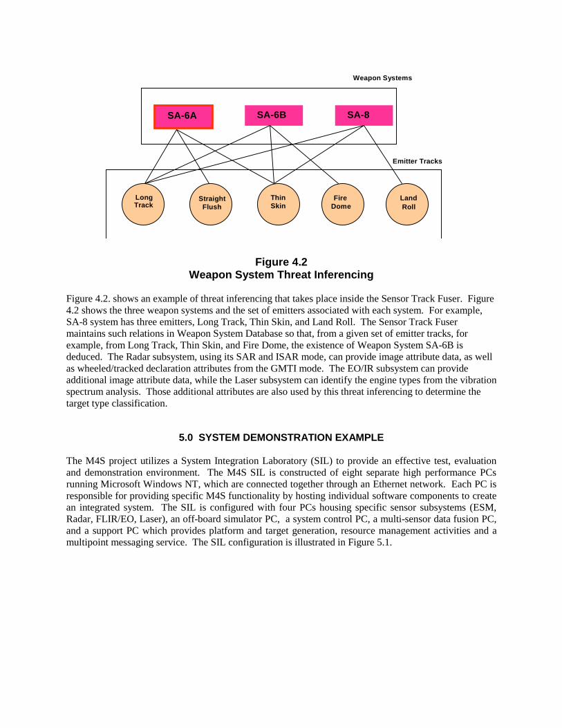
Figure 4.2Weapon System Threat Inferencing
Figure 4.2. shows an example of threat inferencing that takes place inside the Sensor Track Fuser. Figure4.2 shows the three weapon systems and the set of emitters associated with each system. For example,SA-8 system has three emitters, Long Track, Thin Skin, and Land Roll. The Sensor Track Fusermaintains such relations in Weapon System Database so that, from a given set of emitter tracks, forexample, from Long Track, Thin Skin, and Fire Dome, the existence of Weapon System SA-6B isdeduced. The Radar subsystem, using its SAR and ISAR mode, can provide image attribute data, as wellas wheeled/tracked declaration attributes from the GMTI mode. The EO/IR subsystem can provideadditional image attribute data, while the Laser subsystem can identify the engine types from the vibrationspectrum analysis. Those additional attributes are also used by this threat inferencing to determine thetarget type classification.
5.0 SYSTEM DEMONSTRATION EXAMPLE
The M4S project utilizes a System Integration Laboratory (SIL) to provide an effective test, evaluationand demonstration environment. The M4S SIL is constructed of eight separate high performance PCsrunning Microsoft Windows NT, which are connected together through an Ethernet network. Each PC isresponsible for providing specific M4S functionality by hosting individual software components to createan integrated system. The SIL is configured with four PCs housing specific sensor subsystems (ESM,Radar, FLIR/EO, Laser), an off-board simulator PC, a system control PC, a multi-sensor data fusion PC,and a support PC which provides platform and target generation, resource management activities and amultipoint messaging service. The SIL configuration is illustrated in Figure 5.1.

Multi-SensorData Fusion
System
Platform/Target Array Generator;Resource Manager;
Multipoint Message ServerSystem
Controller
ESMSensor
Subsystem
SAR/ISARSensor
Subsystem
EO/IRSensor
Subsystem
LaserSensor
Subsystem
Off-BoardSimulator
EtherNet TCP/IP
98-108-001
Figure 5.1M4S Demonstration Configuration
The M4S system has been developed to support an improvement in the success for tactical andsurveillance missions through the process of multi-sensor data fusion and a closed loop mode ofoperation. Scenarios have been developed to measure the M4S system’s effectiveness for situations suchas ocean surveillance, armored column, and site assessment activities. Due to the flexibility of thearchitecture, M4S supports a “plug and play” type capability to allow for a suite of sensors that willprovide effective land, afloat and air coverage. The M4S demonstration system is illustrated in Figure5.2.
Multi-SensorTarget
Recognition(MSTR)
ResourceManagement
(RM)
SituationAssessment
(SA)
Sensor Subsystems
Data Fusion Process (DFP)TCP/IP
CommsProcessing
{1 to n Sensors}
TacticalDisplay
ProcessingCRT
Sensor Data
Fusion(SDF)
Sensor Subsystems
Off-board Simulator
Platformand
TargetArray
Generator
Figure 5.2M4S Demonstration System

The M4S ocean surveillance scenario starts with the M4S platform beginning it’s flight from the UnitedArab Emirates (UAE) on a mission to detect, classify and localize the position of all surface traffic in theStrait of Hormuz. Slightly after takeoff, the on-board ESM sensor detects ten different radars operating inthe South East portion of the strait. Through the first stages of data fusion, M4S performs track-to-trackassociations to link associated emitters that belong to common platforms together, reducing the situationto five unidentified tracks. The five tracks are determined to be categorized as two hostile and threeunknown ships. The M4S platform is then directed North by resource management activities to provideample sensor coverage by the on-board radar sensor. The ISAR mode is used to acquire the two hostileships in an attempt to identify their ship type. Figure 5.3 shows a visual presentation from the multi-sensor fusion application at the intial stage of the ocean surveillance scenario.
Figure 5.3Ocean Surveillance Scenario Start
After a successful classification of two hostile cruiser class ships determined from the fusion of the ESMand ISAR detections, the M4S platform performs an assessment of the situation to determine the nextcourse of action. Realizing the tracks that have yet to be identified and the suite of sensors M4S hasavailable, the platform is directed to fly East first for positioning and then South to intercept the course ofthe nearest unidentified track. Using the FLIR/EO and Laser sensors a hostile patrol boat is bothidentified and pinpointed for position through the use of multi-sensor data fusion. The combination ofESM detected emissions, FLIR/EO imagery features and Laser detected vibration frequencies areassociated to provide a high confidence classification as well as an accurate position with very littleuncertainty. The radar is allocated in a PPI search mode to maintain track on the hostile patrol boat whilean assessment of the situation is perfomed to direct the platform towards the next unidentified track by theresource manager. Figure 5.4 shows an example of a cruiser class ship with fused information from theon-board ESM, radar, FLIR/EO and Laser sensors.
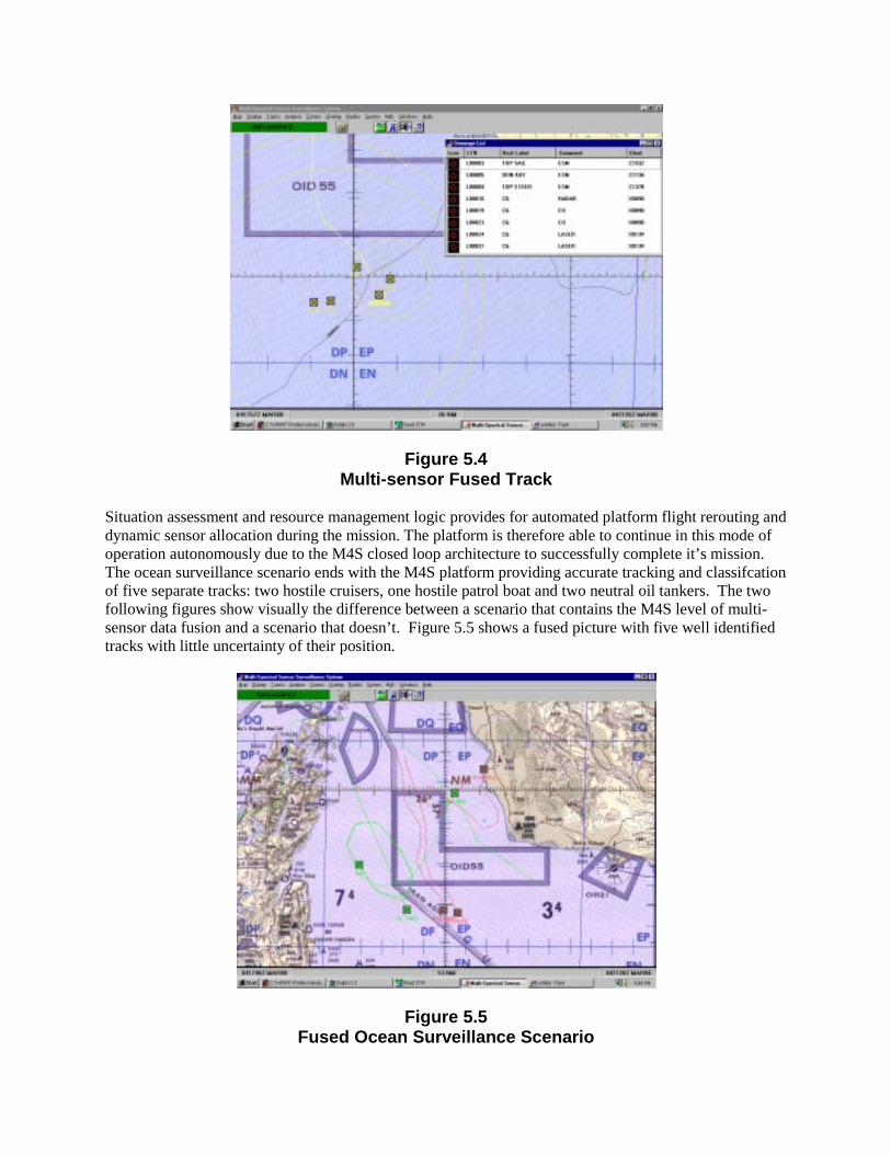
Figure 5.4Multi-sensor Fused Track
Situation assessment and resource management logic provides for automated platform flight rerouting anddynamic sensor allocation during the mission. The platform is therefore able to continue in this mode ofoperation autonomously due to the M4S closed loop architecture to successfully complete it’s mission.The ocean surveillance scenario ends with the M4S platform providing accurate tracking and classifcationof five separate tracks: two hostile cruisers, one hostile patrol boat and two neutral oil tankers. The twofollowing figures show visually the difference between a scenario that contains the M4S level of multi-sensor data fusion and a scenario that doesn’t. Figure 5.5 shows a fused picture with five well identifiedtracks with little uncertainty of their position.
Figure 5.5Fused Ocean Surveillance Scenario

Unlike Figure 5.5, Figure 5.6 illustrates a picture that contains twenty-seven different tracks with a highlevel of uncertainty respresented by the 90% containment ellipses that are drawn for each track.
Figure 5.6Nonfused Ocean Surveillance Scenario
6.0 YEAR-TWO EXTENSIONS
The next step in the proof of concept process for M4S will be to concentrate efforts in closing thecommunications loop between the data fusion process and the sensors. In support of this, the M4S teamwill develop algorithms and techniques for improved Situation Awareness and Resource Management.Multi-sensor data fusion results coupled with area specific Electron Order of Battle (EOB) data will beused to create a tactical picture that will drive resource (air vehicle and sensors) management decisions.Figure 6.1 captures a scenario in which five tanks and two SA8s are identified by the sensors and the datafusion process in an area. Further analysis of this data and the EOB results in an aggregated SituationAwareness picture showing their area of influence. Given this information we may assume a level of aircoverage associated with this column of tanks that may preclude the system from collecting closer rangesensor information in this area. The resource management functions could then task the sensors to collectdata on other targets of interest.
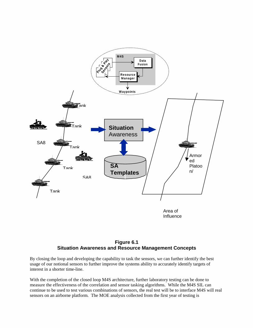
Figure 6.1Situation Awareness and Resource Management Concepts
By closing the loop and developing the capability to task the sensors, we can further identify the bestusage of our notional sensors to further improve the systems ability to accurately identify targets ofinterest in a shorter time-line.
With the completion of the closed loop M4S architecture, further laboratory testing can be done tomeasure the effectiveness of the correlation and sensor tasking algorithms. While the M4S SIL cancontinue to be used to test various combinations of sensors, the real test will be to interface M4S will realsensors on an airborne platform. The MOE analysis collected from the first year of testing is
DataFusion
ResourceManager
W aypoints
M4S
SituationAwareness
SATemplates
Tank
Tank
Tank
Tank
Tank
SA8
ArmoredPlatoon/
Area ofInfluence
SA8

encouraging. Completing the architecture by adding Situation Awareness and a Resource Managershould further serve to improve the systems ability to quickly and efficiently localize and identify tracks.Armed with this data, evaluating M4S on an airborne platform will continue to show how current andnear-term sensor systems can be made even more efficient and useful without any hardwaremodifications. Coupling these sensor systems with M4S will not only allow us to make better use ofcurrent systems but will aid our forces in more effectively locating and identifying critical targets.
REFERENCES
[1] Kathleen A. Demetri, William H. Barker, Shozo Mori, and Richard N. Lineback, “Advanced TacticalWorkstation,” Proc. Of the 1997 IRIS National Symposium on Sensor and Data Fusion, MIT LincolnLab., Lexington, MA, April 1997.
[2] Oliver O. Drummond, “Hybrid Fusion Algorithm Architecture,” Proc. Of the 1997 IRIS NationalSymposium on Sensor and Data Fusion, MIT Lincoln Lab., Lexington, MA, April 1997.
[3] Oliver O. Drummond, “A Hybrid Sensor Fusion Algorithm Architecture and Tracklets,” Proc. Of the1997 SPIE, Signal and Data Processing of Small Targets, SPIE Vol. 3163, San Diego, CA, July 1997.
[4] R. Jonker, and A. Volgenant, “A Shortest Augmenting Path Algorithm for Dense and Sparse LinearAssignment Algorithms,” Computing, Vol. 38, No. 4, 1987.
[5] Shozo Mori, Kathleen A. Demetri, William H. Barker, and Richard N. Lineback, “A TheoreticalFoundation of Data Fusion – Generic Track Association Metric,” Proc. Of the Seventh Data FusionSymposium, Laurel, MD, Oct. 1994.[6] Shozo Mori, Kathleen A. Demetri, William H. Barker, and Richard N. Lineback, “Track AssociationLikelihood Calculation with Non-Deterministic Target Dynamics,” presented at Institute for OperationsResearch and Management Sciences (INFORMS) Washington, DC Spring 96 National Meeting, May 7,1996.
[7] Kenneth Campbell, et al., “Program Overview of the Multi-Spectral Sensor Surveillance System(M4S),” to be presented in the 1998 IRIS National Symposium on Sensor and Data Fusion, Marietta, GA,April, 1998.
[8] Tiburon Systems, “Over-The-Horizon Detection, Classification, Identification, and Tracking(OTH/DC&T) System Level Specification, Ship Tracking Algorithm B,” Submitted to Naval ElectronicSystem Command and Control System, Oct. 1985.